EP3143897B1 - Surface fastener, cushion structure, and seat structure - Google Patents
Surface fastener, cushion structure, and seat structure Download PDFInfo
- Publication number
- EP3143897B1 EP3143897B1 EP15764522.7A EP15764522A EP3143897B1 EP 3143897 B1 EP3143897 B1 EP 3143897B1 EP 15764522 A EP15764522 A EP 15764522A EP 3143897 B1 EP3143897 B1 EP 3143897B1
- Authority
- EP
- European Patent Office
- Prior art keywords
- engagement element
- tilting
- surface fastener
- engagement
- element group
- Prior art date
- Legal status (The legal status is an assumption and is not a legal conclusion. Google has not performed a legal analysis and makes no representation as to the accuracy of the status listed.)
- Active
Links
- 238000009958 sewing Methods 0.000 claims description 25
- 238000005452 bending Methods 0.000 claims description 10
- 229920003002 synthetic resin Polymers 0.000 claims description 10
- 239000000057 synthetic resin Substances 0.000 claims description 10
- 229920005989 resin Polymers 0.000 claims description 7
- 239000011347 resin Substances 0.000 claims description 7
- 229920000728 polyester Polymers 0.000 claims description 4
- 238000003825 pressing Methods 0.000 claims description 4
- 229920001971 elastomer Polymers 0.000 claims description 3
- 239000000806 elastomer Substances 0.000 claims description 3
- 239000004744 fabric Substances 0.000 description 29
- 230000000052 comparative effect Effects 0.000 description 24
- 238000000034 method Methods 0.000 description 24
- 239000004745 nonwoven fabric Substances 0.000 description 21
- 239000000463 material Substances 0.000 description 9
- 238000005259 measurement Methods 0.000 description 9
- 230000003068 static effect Effects 0.000 description 9
- 230000015572 biosynthetic process Effects 0.000 description 6
- 238000006073 displacement reaction Methods 0.000 description 5
- 210000003205 muscle Anatomy 0.000 description 5
- 230000008878 coupling Effects 0.000 description 4
- 238000010168 coupling process Methods 0.000 description 4
- 238000005859 coupling reaction Methods 0.000 description 4
- -1 polybutylene terephthalate Polymers 0.000 description 4
- 239000002759 woven fabric Substances 0.000 description 4
- 210000001217 buttock Anatomy 0.000 description 3
- 238000001125 extrusion Methods 0.000 description 3
- 235000001674 Agaricus brunnescens Nutrition 0.000 description 2
- 239000004743 Polypropylene Substances 0.000 description 2
- 229920005830 Polyurethane Foam Polymers 0.000 description 2
- 230000003247 decreasing effect Effects 0.000 description 2
- 230000000704 physical effect Effects 0.000 description 2
- 229920001155 polypropylene Polymers 0.000 description 2
- 239000011496 polyurethane foam Substances 0.000 description 2
- 229920002972 Acrylic fiber Polymers 0.000 description 1
- 239000004677 Nylon Substances 0.000 description 1
- OAICVXFJPJFONN-UHFFFAOYSA-N Phosphorus Chemical compound [P] OAICVXFJPJFONN-UHFFFAOYSA-N 0.000 description 1
- 239000004721 Polyphenylene oxide Substances 0.000 description 1
- 239000002390 adhesive tape Substances 0.000 description 1
- 229920001400 block copolymer Polymers 0.000 description 1
- 230000000295 complement effect Effects 0.000 description 1
- 230000000694 effects Effects 0.000 description 1
- 238000003780 insertion Methods 0.000 description 1
- 230000037431 insertion Effects 0.000 description 1
- 239000004816 latex Substances 0.000 description 1
- 229920000126 latex Polymers 0.000 description 1
- 239000010985 leather Substances 0.000 description 1
- 239000002649 leather substitute Substances 0.000 description 1
- 239000002184 metal Substances 0.000 description 1
- 229920001778 nylon Polymers 0.000 description 1
- 229910052698 phosphorus Inorganic materials 0.000 description 1
- 239000011574 phosphorus Substances 0.000 description 1
- 229920001707 polybutylene terephthalate Polymers 0.000 description 1
- 229920000570 polyether Polymers 0.000 description 1
- 229920000139 polyethylene terephthalate Polymers 0.000 description 1
- 239000005020 polyethylene terephthalate Substances 0.000 description 1
- 230000000750 progressive effect Effects 0.000 description 1
- 239000000758 substrate Substances 0.000 description 1
- 238000010998 test method Methods 0.000 description 1
- 229920002725 thermoplastic elastomer Polymers 0.000 description 1
- 229920005992 thermoplastic resin Polymers 0.000 description 1
- 210000001519 tissue Anatomy 0.000 description 1
- 238000003466 welding Methods 0.000 description 1
Images


Classifications
-
- B—PERFORMING OPERATIONS; TRANSPORTING
- B60—VEHICLES IN GENERAL
- B60N—SEATS SPECIALLY ADAPTED FOR VEHICLES; VEHICLE PASSENGER ACCOMMODATION NOT OTHERWISE PROVIDED FOR
- B60N2/00—Seats specially adapted for vehicles; Arrangement or mounting of seats in vehicles
- B60N2/58—Seat coverings
- B60N2/5816—Seat coverings attachments thereof
- B60N2/5833—Seat coverings attachments thereof by hook-and-loop type fasteners
-
- A—HUMAN NECESSITIES
- A44—HABERDASHERY; JEWELLERY
- A44B—BUTTONS, PINS, BUCKLES, SLIDE FASTENERS, OR THE LIKE
- A44B18/00—Fasteners of the touch-and-close type; Making such fasteners
- A44B18/0046—Fasteners made integrally of plastics
- A44B18/0049—Fasteners made integrally of plastics obtained by moulding processes
-
- A—HUMAN NECESSITIES
- A44—HABERDASHERY; JEWELLERY
- A44B—BUTTONS, PINS, BUCKLES, SLIDE FASTENERS, OR THE LIKE
- A44B18/00—Fasteners of the touch-and-close type; Making such fasteners
- A44B18/0046—Fasteners made integrally of plastics
- A44B18/0061—Male or hook elements
-
- A—HUMAN NECESSITIES
- A44—HABERDASHERY; JEWELLERY
- A44B—BUTTONS, PINS, BUCKLES, SLIDE FASTENERS, OR THE LIKE
- A44B18/00—Fasteners of the touch-and-close type; Making such fasteners
- A44B18/0069—Details
- A44B18/0073—Attaching means
-
- B—PERFORMING OPERATIONS; TRANSPORTING
- B29—WORKING OF PLASTICS; WORKING OF SUBSTANCES IN A PLASTIC STATE IN GENERAL
- B29C—SHAPING OR JOINING OF PLASTICS; SHAPING OF MATERIAL IN A PLASTIC STATE, NOT OTHERWISE PROVIDED FOR; AFTER-TREATMENT OF THE SHAPED PRODUCTS, e.g. REPAIRING
- B29C48/00—Extrusion moulding, i.e. expressing the moulding material through a die or nozzle which imparts the desired form; Apparatus therefor
- B29C48/03—Extrusion moulding, i.e. expressing the moulding material through a die or nozzle which imparts the desired form; Apparatus therefor characterised by the shape of the extruded material at extrusion
- B29C48/12—Articles with an irregular circumference when viewed in cross-section, e.g. window profiles
-
- B—PERFORMING OPERATIONS; TRANSPORTING
- B60—VEHICLES IN GENERAL
- B60N—SEATS SPECIALLY ADAPTED FOR VEHICLES; VEHICLE PASSENGER ACCOMMODATION NOT OTHERWISE PROVIDED FOR
- B60N2/00—Seats specially adapted for vehicles; Arrangement or mounting of seats in vehicles
- B60N2/58—Seat coverings
- B60N2/5816—Seat coverings attachments thereof
- B60N2/5883—Seat coverings attachments thereof by sewing, stitching or threading
-
- B—PERFORMING OPERATIONS; TRANSPORTING
- B29—WORKING OF PLASTICS; WORKING OF SUBSTANCES IN A PLASTIC STATE IN GENERAL
- B29K—INDEXING SCHEME ASSOCIATED WITH SUBCLASSES B29B, B29C OR B29D, RELATING TO MOULDING MATERIALS OR TO MATERIALS FOR MOULDS, REINFORCEMENTS, FILLERS OR PREFORMED PARTS, e.g. INSERTS
- B29K2067/00—Use of polyesters or derivatives thereof, as moulding material
- B29K2067/006—PBT, i.e. polybutylene terephthalate
-
- B—PERFORMING OPERATIONS; TRANSPORTING
- B29—WORKING OF PLASTICS; WORKING OF SUBSTANCES IN A PLASTIC STATE IN GENERAL
- B29K—INDEXING SCHEME ASSOCIATED WITH SUBCLASSES B29B, B29C OR B29D, RELATING TO MOULDING MATERIALS OR TO MATERIALS FOR MOULDS, REINFORCEMENTS, FILLERS OR PREFORMED PARTS, e.g. INSERTS
- B29K2075/00—Use of PU, i.e. polyureas or polyurethanes or derivatives thereof, as moulding material
-
- B—PERFORMING OPERATIONS; TRANSPORTING
- B29—WORKING OF PLASTICS; WORKING OF SUBSTANCES IN A PLASTIC STATE IN GENERAL
- B29K—INDEXING SCHEME ASSOCIATED WITH SUBCLASSES B29B, B29C OR B29D, RELATING TO MOULDING MATERIALS OR TO MATERIALS FOR MOULDS, REINFORCEMENTS, FILLERS OR PREFORMED PARTS, e.g. INSERTS
- B29K2081/00—Use of polymers having sulfur, with or without nitrogen, oxygen or carbon only, in the main chain, as moulding material
- B29K2081/06—PSU, i.e. polysulfones; PES, i.e. polyethersulfones or derivatives thereof
-
- B—PERFORMING OPERATIONS; TRANSPORTING
- B29—WORKING OF PLASTICS; WORKING OF SUBSTANCES IN A PLASTIC STATE IN GENERAL
- B29K—INDEXING SCHEME ASSOCIATED WITH SUBCLASSES B29B, B29C OR B29D, RELATING TO MOULDING MATERIALS OR TO MATERIALS FOR MOULDS, REINFORCEMENTS, FILLERS OR PREFORMED PARTS, e.g. INSERTS
- B29K2105/00—Condition, form or state of moulded material or of the material to be shaped
- B29K2105/04—Condition, form or state of moulded material or of the material to be shaped cellular or porous
-
- B—PERFORMING OPERATIONS; TRANSPORTING
- B29—WORKING OF PLASTICS; WORKING OF SUBSTANCES IN A PLASTIC STATE IN GENERAL
- B29L—INDEXING SCHEME ASSOCIATED WITH SUBCLASS B29C, RELATING TO PARTICULAR ARTICLES
- B29L2031/00—Other particular articles
- B29L2031/58—Upholstery or cushions, e.g. vehicle upholstery or interior padding
Definitions
- the present invention relates to a surface fastener, a cushioning structure covered with a covering member via the surface fastener, and a seat structure using the cushioning structure.
- a hook surface fastener has protruding engagement elements in a hook shape, a mushroom shape, or an arrowhead shape formed to protrude on a base.
- the protruding engagement elements are ordinarily formed to stand substantially vertically from the base. Accordingly, in an engaged state with an engagement counterpart (loop surface fastener, or the like), the surface fastener exhibits a certain engagement force against tensile forces both in a shear direction (direction horizontal to the surface) and the vertical direction.
- Japanese Patent Application Laid-open No. 2011-24864 and Japanese Patent Application Laid-open No. Hei 7-124004 each disclose a surface fastener including protruding engagement elements tilting in one direction on a base to thereby have an engagement force that differs depending on a tensile direction. This increases the engagement force in a specific direction.
- US 2005/186385 A1 describes a fastener component for securing a loop-carrying member, the fastener component comprising: a tubular structure; and a plurality of discrete projections extending from a surface of the tubular structure, each projection including a molded stem of resin integral with the surface from which the projection extends, and a loop-engageable head formed at a distal end of the stem to overhang the surface, wherein a majority of the projections are directed away from a common, open longitudinal end of the tubular structure to allow longitudinal overlap of the fastener component with a complementary loop-carrying member received from the longitudinal end, but to resist subsequent removal of the loop-carrying member toward the longitudinal end due to engagement of the projections.
- US 4 887 338 A describes an improvement to hook and loop fastening systems of the type comprising one portion composed of backing material having a hooked surface thereon and another portion composed of backing material having a looped surface thereon.
- the improvement allows for releasably fastening two components together with the hook and loop materials in shear and is characterized by a planar member having one of the components attached to the end thereof and having outer faces each having one of the portions of the fastening system thereon; and, a U-shaped shear trap channel member having the other of the components attached to the closed end of the U and having inner faces on the sides of the U each having the other of the portions of the fastening system thereon.
- the shear trap member is adapted to receive the planar member between the inner faces with the portions of the loop fastening portions in engagement; and, is further adapted to have the sides pivoted adjacent the closed end of the U to allow progressive disengagement of the portions of the fastening system.
- a shear-direction engagement force of a surface fastener greatly depends on surface-direction elasticity of the aforesaid protruding engagement elements, and the protruding engagement elements standing substantially vertically as in Patent Document 1 need to be designed to have such elasticity that a predetermined engagement force works in a balanced manner in all the surface directions. If they are designed so that the engagement force works in a balanced manner in all the directions, it becomes difficult to set the engagement force extremely high. In Patent Documents 2, 3, a high engagement force can work only in a specific direction.
- an outer layer member covering a cushioning member of a seat for vehicles such as automobiles is fixed to the cushioning member or the like via a surface fastener.
- the surface fastener used here gives as little feeling of something foreign as possible to a seated person.
- the surface fastener desirably has a higher engagement force, especially a higher engagement force in a shear direction, so as not to be disengaged when the seated person moves.
- the present invention was made in consideration of the above and its object is to provide a surface fastener that does not give a person a feeling of something foreign and can preferably have a higher engagement force especially in a shear direction than conventionally when used as a joining means for a covering member covering a cushioning member, and that is suitable as a joining means used when a cushioning member is covered with a covering member in a cushioning structure to which a predetermined load is applied, preferably in a cushioning structure provided in a seat structure, and to provide a cushioning structure including the surface fastener and a seat structure using the cushioning structure.
- a surface fastener of the present invention is a surface fastener which is used while stacked on a cushioning member to fix a covering member to the cushioning member that is to be covered, the surface fastener being formed of a synthetic resin and including integrally molded base with a 0.1 to 0.9 mm thickness and an engagement element group including at least one engagement element row composed of a plurality of protruding engagement elements with a 0.2 to 0.8 mm protrusion height arranged in a row on one surface of the base, wherein the base coupled to a predetermined position of a joining counterpart has a portion contributing to an occurrence of a bending point, the base has a portion where a modulus of section changes by a 5 to 50% range, and the portion is the portion contributing to the occurrence of the bending point, and the base is coupled to the predetermined position of the joining counterpart by sewing and due to perforations formed by the sewing, the base has the portion where the modulus of section is in a 50 to 9
- the engagement elements include tilting engagement elements standing obliquely from the base, the surface fastener including a tilting engagement element group as part of the engagement element group, including at least one tilting engagement element row as part of the engagement element row, composed of the plural tilting engagement elements arranged in a row.
- the engagement elements include vertical engagement elements standing substantially vertically from the base, the surface fastener including a vertical engagement element group as part of the engagement element group, including at least one vertical engagement element row as part of the engagement element row, composed of the plural vertical engagement elements arranged in a row, and the engagement elements include tilting engagement elements standing obliquely from the base, the surface fastener including a tilting engagement element group as part of the engagement element group, including at least one tilting engagement element row as part of the engagement element row, composed of the plural tilting engagement elements arranged in a row.
- the tilting engagement element group includes a first tilting engagement element group and a second tilting engagement element group each including at least one row of the tilting engagement element row, and first tilting engagement elements belonging to the first tilting engagement element group and second tilting engagement elements belonging to the second tilting engagement element group tilt in directions opposite to each other.
- a boundary portion between the first tilting engagement element group and the second tilting engagement element group is an elementless portion not having the tilting engagement element, and the elementless portion is coupled to the predetermined position of the joining counterpart.
- a cushioning structure of the present invention is a cushioning structure in which a cushioning member is covered with a covering member, the cushioning structure including any one of the above-described surface fasteners which is coupled to a predetermined position of the covering member and via which the cushioning member is covered with the covering member.
- the surface fastener is located on a surface opposite to a load support surface of the cushioning member, and tension generated when a load is applied to the cushioning member causes the tilting engagement elements to further tilt in such a direction as to have increased engagement forces with an engagement counterpart.
- the elementless portion of the surface fastener is located on the surface opposite to the load support surface of the cushioning member, and when the load is applied to the cushioning member, the elementless portion deflects in a pressing direction of the applied load and the first tilting engagement elements belonging to the first tilting engagement element group and the second tilting engagement elements belonging to the second tilting engagement element group, which tilting engagement elements tilt in the opposite directions, further tilt in such directions as to have increased engagement forces with the engagement counterpart.
- a seat structure of the present invention is a seat structure in which a cushioning structure is disposed in a seat cushion part or a seat back part, the seat structure including the above-described cushioning structure.
- a cushioning structure is disposed in a seat cushion part or a seat back part, the seat structure including the above-described cushioning structure.
- an outer layer member is used as the covering member included in the cushioning structure, and the cushioning member is covered with the outer layer member via the surface fastener.
- the surface fastener used is one which is formed of the synthetic resin and in which the base having a predetermined thickness and the engagement element group including the engagement elements with a predetermined protrusion height are integrally formed, and the engagement element rows are each composed of the plural engagement elements arranged in a row and each independently protruding.
- the cushioning member is covered with the covering member via the surface fastener.
- the resistance value of the surface fastener by itself as measured by the handle-o-meter method conforming to the JIS L 1096 E method is 80 to 150 g and thus higher than resistance values of ordinary surface fasteners formed of a woven fabric.
- the static load characteristic obtained from the load-deflection graph when the pressure is applied by the pressure plate with a 30 mm diameter to a portion where the stacked surface fastener and cushioning member overlap with each other approximates the static load characteristic of the similarly measured load-deflection graph of the cushioning member by itself.
- the spring constant of the surface fastener by itself is set to 0.5 N/mm or less.
- the resistance value measured by the handle-o-meter method being higher than those of ordinary surface fasteners formed of a woven fabric means that surface rigidity of the surface fastener of the present invention by itself is high, but the static load characteristic when the surface fastener is stacked on the cushioning member approximates the static load characteristic when the surface fastener is not stacked thereon. Accordingly, the presence of the surface fastener is not likely to give a feeling of something foreign. This is because, due to the high surface rigidity of the surface fastener by itself, the surface fastener locally deforms only a little and has high body pressure dispersibility.
- the surface fastener of the present invention is suitable for joining a covering member of a cushioning member which is given a load due to its contact with a person as in a vehicle seat.
- the base coupled to the predetermined position of the joining counterpart has the portion contributing to the occurrence of a bending point
- the base has the portion where the modulus of section sharply changes by a 5 to 50% range
- the base of the surface fastener is coupled to the predetermined position of the joining counterpart by the sewing and due to the perforations formed by the sewing
- the substrate has the portion where the modulus of section is within a 50 to 90% range of the modulus of section before the sewing. This easily causes the bending along a portion with a low modulus of section (especially the perforation portion) when a load is applied, to increase engagement forces of the engagement elements with the engagement counterpart.
- the surface fastener preferably includes the tilting engagement element group composed of the tilting engagement elements.
- the surface fastener preferably includes the first tilting engagement element group and the second tilting engagement element group which include the engagement elements tilting in the opposite directions. This can more increase the engagement force in a shear direction.
- the cushioning member covered with the outer layer member via this surface fastener is used in the cushioning structure included in the seat structure, and preferably, when the surface fastener is disposed so that the boundary portion between the first tilting engagement element group and the second tilting engagement element group, which portion is an easily bending portion of the surface fastener, serves as a fulcrum of a force of the applied load, the shear direction engagement force in the surface fastener is increased, so that the outer layer member does not easily come off the cushioning member.
- FIGs. 1 illustrate the external structure of an automobile seat S using a cushioning structure 1 according to one embodiment of the present invention.
- the cushioning structure 1 is used in a seat cushion part SC of the automobile seat S.
- a cushioning member 10 is covered with an outer layer member 20 as a covering member via a surface fastener 100.
- the cushioning member 10 is formed of, for example, a polyurethane foam, has a predetermined size and a predetermined thickness, and is supported by a frame of the seat cushion part SC.
- the outer layer member 20 is formed of genuine leather, synthetic leather, fabric, or the like, and covers the cushioning member 10 via the surface fastener 100.
- a vertical engagement element group 120, a first tilting engagement element group 130, and a second tilting engagement element group 140 are provided on a base 110.
- the base 110 and the engagement element groups 120 to 140 of the surface fastener 100 are integrally formed by extrusion molding using a thermoplastic resin as a synthetic resin material.
- the synthetic resin material is extruded from an extrusion nozzle (not illustrated) having a slit having a shape corresponding to the end face shape (same as a section shape) of the base 110 and the engagement element groups 120 to 140 as illustrated in FIG. 3(c) , so that they are integrally molded.
- the surface fastener 100 of this embodiment is molded very thin and is used in the seat cushion part SC which is a part constantly given a load of a person.
- the synthetic resin is preferably a thermoplastic elastomer, more preferably, a polyester elastomer (PES) because they have high strength and are excellent in dimensional stability, impact resistance, heat resistance, and so on even if they are thin.
- the synthetic resin is still more preferably a resin formed of a block copolymer composed of a polybutylene terephthalate block as a hard segment and a polyether block as a soft segment.
- the base 110 has a thin plate shape with a 0.1 to 0.9 mm thickness and has the engagement element groups 120 to 140 formed on its one surface.
- the eight rows on the right in the drawing belong to the vertical engagement element group 120
- the four rows on the left of the vertical engagement element group 120 belong to the first tilting engagement element group 130
- the three rows on the further left belong to the second tilting engagement element group 140.
- the number of rows and so on of each of the engagement element groups 120 to 140 may of course be any.
- the arrangement order of the engagement element groups 120 to 140 is not limited to that illustrated in the drawings, either.
- the vertical engagement element group 120 includes eight vertical engagement element rows 121 having many vertical engagement elements 121a arranged along the row direction and having a substantially mushroom shape whose upper portions protrude leftward and rightward when seen from the end face as illustrated in FIG. 3(d) .
- the vertical engagement elements 121a each have, for example, a 0.2 to 0.8 mm height from the surface of the base 110.
- the PES resin has high strength and excellent dimensional stability and do not easily collapse despite its small height, and thus can exhibit a predetermined engagement force with a joining counterpart.
- the first tilting engagement element group 130 includes four first tilting engagement element rows 131 having many first tilting engagement elements 131a arranged along the row direction and standing from the surface of the base 110 so as to tilt leftward in the drawings, that is, toward the second tilting engagement element group 140 as illustrated in FIGs. 3(c), (d) .
- a tilt angle of the first tilting engagement elements 131a may be any, but is preferably within a range of 30 to 80 degrees, considering easiness of the engagement with the joining counterpart.
- the first tilting engagement elements 131a each preferably have a 0.2 to 0.8 mm vertical-direction height from the surface of the base 110 similarly to the vertical engagement elements 121a.
- the second tilting engagement element group 140 includes three second tilting engagement element rows 141 having many second tilting engagement elements 141a arranged along the row direction and standing from the surface of the base 110 so as to tilt rightward in the drawings, that is, toward the first tilting engagement element group 130 as illustrated in FIGs. 3(c), (d) .
- a preferable tilt angle and a preferable vertical-direction height of the second tilting engagement elements 141a are the same as those of the first tilting engagement elements 131a.
- the vertical engagement elements 121a, the first tilting engagement elements 131a, and the second tilting engagement elements 141a are all formed in a large number in the row direction here, and between the engagement elements adjacent in the row direction, gaps 121b, 131b, 141b each being an independent element are formed. Consequently, the whole surface fastener 100 can have flexibility along the row direction.
- the number of the vertical engagement element rows 121 included in the vertical engagement element group 120, the number of the first tilting engagement element rows 131 included in the first tilting engagement element group 130, and the number of the second tilting engagement element rows 141 included in the second tilting engagement element group 140, and the intervals between these rows may be any as described above, and are determined appropriately in consideration of a required engagement force and other factors. In this embodiment, however, as illustrated in FIGs.
- the intervals between the adjacent rows in a region from the right end vertical engagement element row 121 up to the left end first tilting engagement element row 131 are all equal, and the intervals of the three second tilting engagement element rows 141 are also equal, but an interval between the left end first tilting engagement element row 131 and the right end second tilting engagement element row 141 is wider than the other intervals between the rows. That is, a range between the left end first tilting engagement element row 131 and the right end second tilting engagement element row 141, where the surface of the base 110 is exposed, is an elementless portion 150 having no engagement element.
- the elementless portion 150 is coupled to a predetermined position of a joining counterpart, coupled to a predetermined position of the outer layer member 20 which is a covering member covering the cushioning member 10. More specifically, in this embodiment, a first and a second drawing fabric 21, 22 are attached to edges of the outer layer member 20 in order to draw the outer layer member 20 from both sides of the seat frame to a rear surface side of the cushioning member 10 to draw it in the center direction of the rear surface side of the cushioning member 10.
- the first drawing fabric 21 is stacked on the rear surface of the base 110 of the surface fastener 100 and an end portion of the first drawing fabric 21 is coupled to a position of the elementless portion 150 by sewing.
- the engagement element groups 120 to 140 located on the front surface side of the base 110 are joined to an engagement counterpart.
- the engagement counterpart mentioned here refers to a mate part with which the engagement elements 121a to 141a forming the engagement element rows 121 to 141 of the engagement element groups 120 to 140 are engaged, and may be a loop surface fastener making a pair with the hook surface fastener of this embodiment including the engagement elements 121a to 141a or may be a nonwoven fabric having no special loop.
- the second drawing fabric 22 drawn to the rear surface side of the cushioning member 10 is formed of a nonwoven fabric and works as the engagement counterpart, and the engagement elements 121a to 141a forming the engagement element rows 121 to 141 of the engagement element groups 120 to 140 of the surface fastener 100 are engaged with the second drawing fabric 22.
- a sewing means is used for the coupling of the surface fastener 100 and the first drawing fabric 21 here.
- perforations (holes) are formed as a result of the sewing. Due to the perforations (holes), a modulus of section in this portion reduces. Because of the reduced modulus of section, the surface fastener 100 easily bends along the perforations (holes) of the elementless portion 150 which is the portion coupled by the sewing. Accordingly, when the first drawing fabric 21 is pulled, the surface fastener 100 surely bends along the perforations (holes) of the elementless portion 150.
- the first tilting engagement elements 131a belonging to the first engagement element group 130 which tilt in one direction and the second tilting engagement elements 141a belonging to the second tilting engagement element group 140 which tilt in the opposite direction penetrate in the second drawing fabric 22, so that their engagement forces more increase.
- the modulus of section is within a range of 50 to 95%, preferably within a range of 70 to 90%, of that before the sewing, with respect to 100 being a modulus of section of a range which is along the line of the perforations (holes) and is surrounded by the width (diameter) of the perforations (holes) and the length of the surface fastener 100 along the line of the perforations (holes), as illustrated in FIGs. 7 . Too low a modulus of section results in an excessive decrease of strength when the elementless portion 150 is pulled, and too high a modulus of section results in a decreased operation of the bending along the perforations (holes).
- the modulus of section is 50 to 83% of that before the sewing when the sewing pitch is 3 mm
- the modulus of section is 70 to 90% of that before the sewing when the sewing pitch is 5 mm
- the modulus of section is 78.6 to 92.9% of that before the sewing when the sewing pitch is 7 mm.
- the use of the sewing means can simultaneously and easily achieve a means for coupling the surface fastener 100 and the first drawing fabric 21 and a means for forming the easily bending part by decreasing the modulus of section.
- the means for forming the easily bending part in the elementless portion 150 can be, for example, a means which molds the elementless portion 150 into a shape with a small modulus of section in advance, or a means which joins the first drawing fabric 21 and the elementless portion 150 by vibration welding or the like and at this time works the elementless portion 150 into a thin shape, but this does not form part of the claimed invention.
- the cushioning member 10 sinks and as illustrated in FIG. 1(c) , tensions act in directions so that the first and second drawing fabrics 21, 22 drawn to the rear side from the both sides of the outer layer member 20 are pulled outward from the center.
- the action of the tensions deflects the elementless portion 150, which is the coupling position with the first drawing fabric 21, in a downward direction which is a pressing direction of a load of the person.
- the first tilting engagement elements 131a of the first tilting engagement element rows 131 belonging to the first tilting engagement element group 130 and the second tilting engagement elements 141a of the second tilting engagement element rows 141 belonging to the second tilting engagement element group 140 which tilting engagement elements face each other across the elementless portion 150 and tilt in the opposite directions, further penetrate in the second drawing fabric 22 to have increased engagement forces. That is, even if forces act in the shear direction on the first and second drawing fabrics 21, 22 when a person is seated, the tilting engagement elements 131a, 141a further penetrate to have increased engagement forces in the shear direction.
- the tilting engagement elements 131a, 141a thus penetrate so as to have the increased engagement forces when the tensions act on the elementless portion 150 which is the coupling portion. Therefore, the first tilting engagement element row 131 (first tilting engagement element group 130) having the first tilting engagement elements 131a and the second tilting engagement element row 141 (second tilting engagement element group 140) having the second tilting engagement elements 141a are essential.
- engagement forces of the vertical engagement element row 121 (vertical engagement element group 120) having the vertical engagement elements 121a are increased only slightly by the tensions, but they have engagement forces acting in all the shear directions and thus are preferably provided as in this embodiment.
- the base 110 has a 0.1 to 0.9 mm thickness and the engagement elements 121a to 141a each have a 0.2 to 0.8 mm height from the surface of the base 110 as described above.
- the surface fastener 100 since the surface fastener 100 is disposed on the rear surface side of the cushioning member 10, a person basically does not feel the presence of the surface fastener 100 when seated, but if the surface fastener 100 is disposed on the front surface side of the cushioning member 10 and the outer layer member 20 is joined therewith, the person may feel the presence of the surface fastener 100 when seated.
- the base 110 is thin and the engagement elements 121a to 141a each have a low protrusion height as described above, and accordingly the whole thickness of the surface fastener 100 is also within a range of 0.3 to 1.7 mm, preferably within a range of 0.5 to 1.2 mm. Even if the surface fastener 100, which is thus very thin, is disposed on the front surface side of the cushioning member 10 and joined with the outer layer member 20, a seated person scarcely feels the presence of the surface fastener 100.
- the surface fastener 100 needs to have high follow-up ability to the cushioning member 10 in addition to satisfying the above thickness requirement.
- the surface fastener 100 gives a less feeling of something foreign by deforming similarly to the cushioning member 10.
- the engagement elements 121a to 141a of the surface fastener 100 need to have high engagement forces in the shear direction.
- the surface fastener 100 is required to maintain predetermined surface rigidity in an independent state, and not to locally deform in the state of being stacked on the cushioning member 10, and preferably has the following properties in addition to the aforesaid thickness condition and the aforesaid condition of the used synthetic resin material (preferably, the PES resin).
- the surface fastener 100 is fabricated so that a resistance value of the surface fastener 100 by itself as measured by a handle-o-meter method conforming to the JIS L 1096 E method falls within a range of 80 to 150 g. With the resistance value falling within this range, the surface fastener 100 can have predetermined surface rigidity, and the engagement elements 121a to 141a do not collapse and can have high engagement forces even if the peeling force in the surface direction is applied. Further, in the stacked state on the cushioning member 10, the surface fastener 100 is less likely to undergo large partial deformation due to a concentrated load, deforms along the deformation of the cushioning member 10, and thus gives no feeling of something foreign.
- the surface fastener 100 of the example 1 was fabricated by extrusion molding of a standard PES resin. Its structure is as illustrated in FIGs. 2 and FIGs. 3 . It has the eight vertical engagement element rows 121, the four first tilting engagement element rows 131, the three second tilting engagement element rows 141, and the elementless portion 150 formed between the first tilting engagement element rows 131 and the second tilting engagement element rows 141.
- the element rows 121 to 141 each had a 30 mm width in a perpendicular direction to the rows, the base 110 had a 0.32 mm thickness, the vertical engagement elements 121a each had a 0.62 mm protrusion height (vertical height) from the base 110, and the first tilting engagement elements 131a and the second tilting engagement elements 141a each had a 0.51 mm protrusion height (vertical height) from the base 110.
- the surface fastener of the comparative example 1 was as follows:
- the nonwoven fabric of the comparative example 2 was as follows: constituting material:
- the length of the test samples was set to 150 mm.
- Length-direction rigidity of each of the test samples was measured by a cantilever method, with a hook (engagement element) formation surface facing upward (hook facing upward) and with the hook formation surface facing downward (hook facing downward).
- the length of the test samples was set to 250 mm (effective length 200 mm), they were fixed by a jig, and one minute later, the measurement was conducted.
- the hook (engagement element) formation surface facing inward (hook facing inward) and with the hook formation surface facing outward (hook facing outward) heart loops were formed and the length-direction rigidity of each of the test samples was measured by a heart loop method.
- test samples were each suspended in a space between a pair of plates set at a predetermined interval, a blade was moved down in the space by 8 mm from the surface of a test stand, and a value (g) of resistance encountered by the blade at this time was measured.
- Length-direction rigidity of each of the samples was measured by a handle-o-meter method when the plates each had a 30 mm width and the test samples were each disposed so that its length direction was along a direction perpendicular to the longitudinal direction of the space.
- width-direction rigidity of each of the samples was measured by the handle-o-meter method when the plates each had a 16 mm width and the test samples were each disposed so that its length direction was along the longitudinal direction of the space between the plates. The measurement in the both cases was conducted, with the hook (engagement element) formation surface facing inward (hook facing inward) and with the hook formation surface facing outward (hook facing outward).
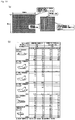
- FIG. 8 shows test results of the rigidity tests.
- the example 1 when the hook faced downward, the example 1 exhibited high rigidity, whose value was not measurable, but an average value when the hook faced upward was 99 mm.
- the comparative example 1 when the hook faced upward, the comparative example 1 exhibited high rigidity, whose value was not measurable, but an average value when the hook faced downward was 97 mm. So, the rigidity test by the cantilever method did not show a substantial difference between the example 1 and the comparative example 1, though there is a difference in the facing direction.
- the example 1 and the comparative example 1 exhibited substantially an equal value and there was not a substantial difference therebetween.
- the example 1 exhibited a 119 g average value when the hook faced upward and a 132 g average value when the hook faced downward, whereas the comparative example 1 exhibited a 43 g average value when the hook faced upward and a 49 g average value when the hook faced downward. Therefore, the example 1 had approximately 2.5 times to three times as high rigidity as that of the comparative example 1.
- the example 1 exhibited a 99 g average value when the hook faced upward and a 120 g average value when the hook faced downward, whereas the comparative example 1 exhibited a 30 g average value when the hook faced upward and a 36 g average value when the hook faced downward. Therefore, the example 1 had approximately three times to four times as high rigidity as that of the comparative example 1.
- the surface fastener of the example 1 exhibited noticeably higher rigidity than the comparative example 1 in the rigidity test by the handle-o-meter method.
- the resistance value of the example 1 as measured by the handle-o-meter method is preferably within a range of 80 to 150 g, since the smallest measurement value is 87 g and the largest measurement value is 141g, though the aforesaid average value is 99 to 132g.
- the resistance value measured by the handle-o-meter method which is a test using the pressing with the blade, indicates flexural rigidity of the test samples when they are given a local concentrated load.
- the surface fastener of the example 1 has higher flexural rigidity against the local concentrated load than the comparative example 1, though the rigidity of the whole test sample as measured by the cantilever method and the heart loop method has no substantial difference from that of the comparative example 1.
- This shows that the surface fastener 100 of the example 1 is not locally distorted and thus does not easily peel off from an engagement counterpart even if pulled in the shear direction (surface direction) while engaged with the engagement counterpart.
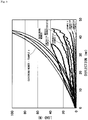
- FIG. 9 shows results.
- FIG. 9 also illustrates a characteristic of the cushioning member 10 by itself and a characteristic of the surface fastener 100 of the example 1 by itself calculated from the data obtained when the surface fastener 100 of the example 1 is stacked on the cushioning member 10.
- FIG. 9 also illustrates characteristics of the comparative example 1 by itself, the comparative example 2 by itself, the comparative example 3 by itself, and the comparative example 4 by itself which were found by calculation after the above measurement.
- FIG. 9 also illustrates a typical example (muscle characteristic) of the static load characteristic when a pressure up to 100 N is applied to the muscle of the buttocks of a person by a pressure plate with a 30 mm diameter.
- a hysteretic characteristic of the load-deflection graph when the surface fastener 100 of the example 1 is stacked on the cushioning member 10 is within a ⁇ 5% range of a hysteretic characteristic of the load-deflection graph of the cushioning member 10 by itself, and the both hysteretic characteristics depict substantially the same trajectory, when they are compared in a range where the load value is 40 N or more.
- the spring constant of the surface fastener by itself is 0.5 N/mm or less in any of deflection amount segments, and when the spring constant was calculated in various deflection amount segments, its lower values were 0 N/mm, 0.05 N/mm, 0.1 N/mm, and so on.
- the spring constant of the surface fastener by itself is equal to or less than the spring constant of the muscle of the buttocks of a person, which is within a range of roughly 0.2 to 1 N/mm.
- the surface fastener 100 of the example 1 has high flexural rigidity as described above, yet it satisfies the conditions that it should have high follow-up ability to the deformation of the cushioning member 10 when stacked on the cushioning member 10, and the spring constant of the surface fastener 100 by itself should be smaller than the spring constant of the muscle characteristics. Accordingly, even if the surface fastener 100 of the example 1 is disposed, a person scarcely feels its presence. On the other hand, it can exhibit a high engagement force in the shear direction owing to the aforesaid flexural rigidity that it has.
- a fabric corresponding to the first drawing fabric 21 is coupled to the surface fastener 100 of the example 1 by sewing, and nonwoven fabrics A, B corresponding to the second drawing fabric 22 were each joined to the surface fastener 100, and the engagement force was measured.
- the surface fastener 100 had a 50 mm length and a 30 mm width
- the fabric corresponding to the first drawing fabric 21 had a 60 mm length and a 60 mm width
- the nonwoven fabrics corresponding to the second drawing fabric 22 each had an 80 mm length and a 100 mm width.
- the nonwoven fabric A corresponding to the second drawing fabric 22 was the nonwoven fabric of the above-described comparative example 2, and the nonwoven fabric B had a 130 (125 ⁇ 13) g/m 2 weight and a 1.35 mm thickness which were less than those of the nonwoven fabric A.
- the above samples were pulled in the width direction perpendicular to the row direction of the engagement element rows 121, 131, 141 of the surface fastener 100.
- the measurement was conducted for a case where a tensile direction of the surface fastener 100 was a flow direction of the nonwoven fabrics A, B and for a case where the tensile direction is the width direction perpendicular to the flow direction.
- FIG. 10(b) shows results.
- shear strength, 5° peel strength, and 10° peel strength had high values of 10 N/cm 2 or more.
- 45° peel strength was about 1/2 of the shear strength, the 5° peel strength, and the 10° peel strength.
- the peel strength and perpendicular strength were about 1/4 of the shear strength, the 5° peel strength, or the 10° peel strength.
- the samples were each pasted on a SUS plate with an adhesive tape.
- a perpendicular insertion pressure was set to 50 N/engagement area.
- the shear strength was about 8 N/cm 2 and thus lower than in the case of the nonwoven fabric A. Therefore, the nonwoven fabric A is preferably used as a mate member (second drawing fabric 22) engaged with the surface fastener 100 of the example 1.
- the nonwoven fabric B has shear strength about four times as high as the peel strength and the perpendicular strength, and thus even if the nonwoven fabric B is the mate member, a high engagement force can be exhibited in the shear direction.
- the surface fastener of the present invention exhibits a high engagement force when used so as to be pulled in the shear direction at 10° or less (15° or less in calculation).
- the surface fastener of the present invention exhibits a high engagement force as described above. Therefore, it can be used not only for fixing the covering member to the cushioning member but also as a means for fixing a floor mat 1000 laid on a floor of a vehicle such as an automobile as illustrated in FIGs. 11(a) to (d) , for instance.
- a metal surface of a floor surface of especially an automobile is not exposed as it is but is covered with a floor carpet 1100, and thus the engagement elements 121a, 131a, 141a of the surface fastener 100 are engageable therewith.
- a possible alternative structure, not illustrated, is to fix the surface fasteners 100 on the floor carpet 1100 side in advance and engage the engagement elements 121a, 131a, 141a with the rear surface of the floor mat 1000.
- the floor mat 1000 at the driver seat will be a factor to interfere with the accelerator pedal or the brake pedal, but the surface fastener 100 is effective for preventing the displacement of the floor mat 1000 because of its high engagement force in the shear direction as described above.
- the surface fastener 100 for preventing the displacement of the floor mat 1000 does not usually give a feeling of something foreign to a person when disposed on the rear surface of the floor mat 1000, and thus a high engagement force in the shear direction is considered as more important. Accordingly, surface fasteners 100 in modes having the following structures in the above-described structure of the surface fastener 100 are suitable for preventing the displacement of the floor mat 1000.
- engagement elements provided on a base include tilting engagement elements standing obliquely from the base, and the surface fastener 100 includes a tilting engagement element group as the aforesaid engagement element group, including at least one tilting engagement element row as the aforesaid engagement element row, composed of the plural tilting engagement elements arranged in a row.
- engagement elements provided on a base include vertical engagement elements standing substantially vertically from the base, the surface fastener 100 including: a vertical engagement element group as the aforesaid engagement element group, including at least one vertical engagement element row as the aforesaid engagement element row, composed of the plural vertical engagement elements arranged in a row, and the engagement elements provided on the base include tilting engagement elements standing obliquely from the base, the surface fastener 100 including a tilting engagement element group as the aforesaid engagement element group, including at least one tilting engagement element row as the aforesaid engagement element row, composed of the plural tilting engagement elements arranged in a row.
- the tilting engagement element group includes a first tilting engagement element group and a second tilting engagement element group each having at least one tilting engagement element row, and first tilting engagement elements belonging to the first tilting engagement element group and second tilting engagement elements belonging to the second tilting engagement element group tilt in opposite directions to each other.
- the surface fastener 100 may give a feeling of something foreign if the engagement elements 121a, 131a, 141a are too high, and thus it is of course preferable that the surface fastener has the same physical properties as those of the above-described embodiment, regarding the thickness of the base 110, the protrusion height of the engagement elements 121a, 131a, 141a, the resistance value measured by the handle-o-meter method, the hysteretic characteristic of the load-deflection graph, the spring constant, and so on.
- the surface fastener 100 is desirably as thin as possible since an excessively high thickness of the surface fastener 100 involves a problem of an increase of the height of the floor mat 1000 (an increase of the total thickness of the floor mat 1000 and the surface fastener 100). Further, in a case where the surface fastener 100 is fixed to a portion having slight irregularities such as the periphery of a cover of a bracket of a slider, the surface fastener 100 desirably has flexibility or softness so as to deform along the shape of this portion, in order to increase joining strength. In this respect, one having the physical properties of the above-described embodiment is especially preferable since it is thin and flexible and has a high engagement force in the shear direction.
- the floor mat is not limited to that for vehicles but may be that used in a place inside a building such as an entrance, a bathroom, or a kitchen, that used outdoors, and the like. If a material with which the engagement elements of the surface fastener are engageable is provided on a corresponding floor surface, the surface fastener is also useful for preventing a floor mat on the floor surface from slipping.
- the surface fastener of the present invention is usable as the fixing means for various kinds of articles as described above, and in addition, is usable for moving an article having a material surface corresponding to the loop side with which the surface fastener of the present invention is engageable, such as a nonwoven fabric, in a desired direction by being engaged with the article.
- the surface fastener is usable for pulling the article out of a casing (for example, a dispenser of tissue paper or other paper, or towel or other fabrics), for moving the article from a certain position to another position, or for other such purposes.
Description
- The present invention relates to a surface fastener, a cushioning structure covered with a covering member via the surface fastener, and a seat structure using the cushioning structure.
- As is disclosed in
Japanese Patent Application Laid-open No. 2013-123438 -
Japanese Patent Application Laid-open No. 2011-24864 Japanese Patent Application Laid-open No. Hei 7-124004 - Additionally,
US 2005/186385 A1 describes a fastener component for securing a loop-carrying member, the fastener component comprising: a tubular structure; and a plurality of discrete projections extending from a surface of the tubular structure, each projection including a molded stem of resin integral with the surface from which the projection extends, and a loop-engageable head formed at a distal end of the stem to overhang the surface, wherein a majority of the projections are directed away from a common, open longitudinal end of the tubular structure to allow longitudinal overlap of the fastener component with a complementary loop-carrying member received from the longitudinal end, but to resist subsequent removal of the loop-carrying member toward the longitudinal end due to engagement of the projections. - Moreover,
US 4 887 338 A describes an improvement to hook and loop fastening systems of the type comprising one portion composed of backing material having a hooked surface thereon and another portion composed of backing material having a looped surface thereon. The improvement allows for releasably fastening two components together with the hook and loop materials in shear and is characterized by a planar member having one of the components attached to the end thereof and having outer faces each having one of the portions of the fastening system thereon; and, a U-shaped shear trap channel member having the other of the components attached to the closed end of the U and having inner faces on the sides of the U each having the other of the portions of the fastening system thereon. The shear trap member is adapted to receive the planar member between the inner faces with the portions of the loop fastening portions in engagement; and, is further adapted to have the sides pivoted adjacent the closed end of the U to allow progressive disengagement of the portions of the fastening system. - A shear-direction engagement force of a surface fastener greatly depends on surface-direction elasticity of the aforesaid protruding engagement elements, and the protruding engagement elements standing substantially vertically as in
Patent Document 1 need to be designed to have such elasticity that a predetermined engagement force works in a balanced manner in all the surface directions. If they are designed so that the engagement force works in a balanced manner in all the directions, it becomes difficult to set the engagement force extremely high. InPatent Documents 2, 3, a high engagement force can work only in a specific direction. - In many cases, an outer layer member covering a cushioning member of a seat for vehicles such as automobiles is fixed to the cushioning member or the like via a surface fastener. Desirably, the surface fastener used here gives as little feeling of something foreign as possible to a seated person. In addition, the surface fastener desirably has a higher engagement force, especially a higher engagement force in a shear direction, so as not to be disengaged when the seated person moves.
- The present invention was made in consideration of the above and its object is to provide a surface fastener that does not give a person a feeling of something foreign and can preferably have a higher engagement force especially in a shear direction than conventionally when used as a joining means for a covering member covering a cushioning member, and that is suitable as a joining means used when a cushioning member is covered with a covering member in a cushioning structure to which a predetermined load is applied, preferably in a cushioning structure provided in a seat structure, and to provide a cushioning structure including the surface fastener and a seat structure using the cushioning structure.
- To solve the aforesaid problems, a surface fastener of the present invention is a surface fastener which is used while stacked on a cushioning member to fix a covering member to the cushioning member that is to be covered, the surface fastener being formed of a synthetic resin and including integrally molded base with a 0.1 to 0.9 mm thickness and an engagement element group including at least one engagement element row composed of a plurality of protruding engagement elements with a 0.2 to 0.8 mm protrusion height arranged in a row on one surface of the base, wherein the base coupled to a predetermined position of a joining counterpart has a portion contributing to an occurrence of a bending point, the base has a portion where a modulus of section changes by a 5 to 50% range, and the portion is the portion contributing to the occurrence of the bending point, and the base is coupled to the predetermined position of the joining counterpart by sewing and due to perforations formed by the sewing, the base has the portion where the modulus of section is in a 50 to 95% range of a modulus of section before the sewing, and the portion is the portion where the modulus of section changes. Preferably, the synthetic resin is a polyester elastomer (PES) resin.
- Preferably, in the surface fastener of the present invention, the engagement elements include tilting engagement elements standing obliquely from the base, the surface fastener including a tilting engagement element group as part of the engagement element group, including at least one tilting engagement element row as part of the engagement element row, composed of the plural tilting engagement elements arranged in a row.
- Preferably, in the surface fastener of the present invention, the engagement elements include vertical engagement elements standing substantially vertically from the base, the surface fastener including a vertical engagement element group as part of the engagement element group, including at least one vertical engagement element row as part of the engagement element row, composed of the plural vertical engagement elements arranged in a row, and the engagement elements include tilting engagement elements standing obliquely from the base, the surface fastener including a tilting engagement element group as part of the engagement element group, including at least one tilting engagement element row as part of the engagement element row, composed of the plural tilting engagement elements arranged in a row.
- Preferably, the tilting engagement element group includes a first tilting engagement element group and a second tilting engagement element group each including at least one row of the tilting engagement element row, and first tilting engagement elements belonging to the first tilting engagement element group and second tilting engagement elements belonging to the second tilting engagement element group tilt in directions opposite to each other. Preferably, a boundary portion between the first tilting engagement element group and the second tilting engagement element group is an elementless portion not having the tilting engagement element, and the elementless portion is coupled to the predetermined position of the joining counterpart.
- A cushioning structure of the present invention is a cushioning structure in which a cushioning member is covered with a covering member, the cushioning structure including any one of the above-described surface fasteners which is coupled to a predetermined position of the covering member and via which the cushioning member is covered with the covering member.
- Preferably, the surface fastener is located on a surface opposite to a load support surface of the cushioning member, and tension generated when a load is applied to the cushioning member causes the tilting engagement elements to further tilt in such a direction as to have increased engagement forces with an engagement counterpart. Preferably, the elementless portion of the surface fastener is located on the surface opposite to the load support surface of the cushioning member, and when the load is applied to the cushioning member, the elementless portion deflects in a pressing direction of the applied load and the first tilting engagement elements belonging to the first tilting engagement element group and the second tilting engagement elements belonging to the second tilting engagement element group, which tilting engagement elements tilt in the opposite directions, further tilt in such directions as to have increased engagement forces with the engagement counterpart.
- A seat structure of the present invention is a seat structure in which a cushioning structure is disposed in a seat cushion part or a seat back part, the seat structure including the above-described cushioning structure. Preferably, an outer layer member is used as the covering member included in the cushioning structure, and the cushioning member is covered with the outer layer member via the surface fastener.
- As the surface fastener, used is one which is formed of the synthetic resin and in which the base having a predetermined thickness and the engagement element group including the engagement elements with a predetermined protrusion height are integrally formed, and the engagement element rows are each composed of the plural engagement elements arranged in a row and each independently protruding. The cushioning member is covered with the covering member via the surface fastener. The resistance value of the surface fastener by itself as measured by the handle-o-meter method conforming to the JIS L 1096 E method is 80 to 150 g and thus higher than resistance values of ordinary surface fasteners formed of a woven fabric. On the other hand, the static load characteristic obtained from the load-deflection graph when the pressure is applied by the pressure plate with a 30 mm diameter to a portion where the stacked surface fastener and cushioning member overlap with each other approximates the static load characteristic of the similarly measured load-deflection graph of the cushioning member by itself. Further, the spring constant of the surface fastener by itself is set to 0.5 N/mm or less.
- The resistance value measured by the handle-o-meter method being higher than those of ordinary surface fasteners formed of a woven fabric means that surface rigidity of the surface fastener of the present invention by itself is high, but the static load characteristic when the surface fastener is stacked on the cushioning member approximates the static load characteristic when the surface fastener is not stacked thereon. Accordingly, the presence of the surface fastener is not likely to give a feeling of something foreign. This is because, due to the high surface rigidity of the surface fastener by itself, the surface fastener locally deforms only a little and has high body pressure dispersibility. Further, since the spring constant of the surface fastener by itself is equal to or less than 0.2 to 1 N/mm which is a spring constant of the muscle of the buttocks of a person, the surface fastener is not likely to give a feeling of something foreign. Therefore, the surface fastener of the present invention is suitable for joining a covering member of a cushioning member which is given a load due to its contact with a person as in a vehicle seat.
- Further, the base coupled to the predetermined position of the joining counterpart has the portion contributing to the occurrence of a bending point, the base has the portion where the modulus of section sharply changes by a 5 to 50% range, the base of the surface fastener is coupled to the predetermined position of the joining counterpart by the sewing and due to the perforations formed by the sewing, the substrate has the portion where the modulus of section is within a 50 to 90% range of the modulus of section before the sewing. This easily causes the bending along a portion with a low modulus of section (especially the perforation portion) when a load is applied, to increase engagement forces of the engagement elements with the engagement counterpart. As the engagement element group, the surface fastener preferably includes the tilting engagement element group composed of the tilting engagement elements. Further, the surface fastener preferably includes the first tilting engagement element group and the second tilting engagement element group which include the engagement elements tilting in the opposite directions. This can more increase the engagement force in a shear direction.
- Therefore, when the cushioning member covered with the outer layer member via this surface fastener is used in the cushioning structure included in the seat structure, and preferably, when the surface fastener is disposed so that the boundary portion between the first tilting engagement element group and the second tilting engagement element group, which portion is an easily bending portion of the surface fastener, serves as a fulcrum of a force of the applied load, the shear direction engagement force in the surface fastener is increased, so that the outer layer member does not easily come off the cushioning member.
-
- [
FIGs. 1] FIG. 1(a) is a perspective view of an automobile seat covered with an outer layer member which is fixed using a surface fastener according to one embodiment of the present invention,FIG. 1(b) is a cross-sectional view taken along the A-A line in (a) in a load-free state where no load is applied to a seat cushion, andFIG. 1(c) is a cross-sectional view taken along the A-A line in (a) in a loaded state where a load is applied to the seat cushion. - [
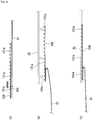
FIGs. 2] FIG. 2(a) is a perspective view illustrating the surface fastener according to the embodiment, andFIG. 2(b) is an enlarged view of the A portion in (a). - [
FIGs. 3] FIG. 3(a) is a plane view of the surface fastener illustrated inFIGs. 2 ,FIG. 3(b) is a side view of (a),FIG. 3(c) is an end view of (a), andFIG. 3(d) is an enlarged view of the B portion in (c). - [
FIGs. 4] FIGs. 4(a) to (c) are views illustrating a process of attaching the surface fastener according to the embodiment to a drawing fabric and thereafter joining the surface fastener to an engagement counterpart. - [
FIGs. 5] FIGs. 5(a), (b) are explanatory views of the operation of the surface fastener according to the embodiment. - [
FIGs. 6] FIGs. 6(a), (b) are explanatory views of the operation of sewing perforations of the surface fastener according to the embodiment. - [
FIGs. 7] FIG. 7(a) is a view illustrating an example of the size (diameter) of the perforations and intervals between the perforations, andFIG. 7(b) is an enlarged view of the C portion in (a). - [
FIG. 8] FIG. 8 is a chart showing results of rigidity tests. - [
FIG. 9] FIG. 9 is a chart showing results of a test on static load characteristics. - [
FIGs. 10] FIG. 10(a) is a view illustrating the sizes of samples used in an engagement force test, andFIG. 10(b) is a chart showing test results of the engagement force test. - [
FIGs. 11] FIG. 11(a) is a plane view illustrating a mode where the surface fastener of the present invention is used to fix a floor mat,FIG. 11(b) is a view seen in the direction of the arrow A inFIG. 11(a), FIG. 11(c) is an exploded perspective view, andFIG. 11(d) is a perspective view illustrating a state where the floor mat is fixed to a floor carpet. - The present invention will be hereinafter described in more detail based on embodiments illustrated in the drawings.
FIGs. 1 illustrate the external structure of an automobile seat S using acushioning structure 1 according to one embodiment of the present invention. In this embodiment, thecushioning structure 1 is used in a seat cushion part SC of the automobile seat S. In thecushioning structure 1, a cushioningmember 10 is covered with anouter layer member 20 as a covering member via asurface fastener 100. - The cushioning
member 10 is formed of, for example, a polyurethane foam, has a predetermined size and a predetermined thickness, and is supported by a frame of the seat cushion part SC. Theouter layer member 20 is formed of genuine leather, synthetic leather, fabric, or the like, and covers the cushioningmember 10 via thesurface fastener 100. - As illustrated in
FIGs. 2 andFIGs. 3 , in thesurface fastener 100, a verticalengagement element group 120, a first tiltingengagement element group 130, and a second tiltingengagement element group 140 are provided on abase 110. Thebase 110 and theengagement element groups 120 to 140 of thesurface fastener 100 are integrally formed by extrusion molding using a thermoplastic resin as a synthetic resin material. Specifically, the synthetic resin material is extruded from an extrusion nozzle (not illustrated) having a slit having a shape corresponding to the end face shape (same as a section shape) of thebase 110 and theengagement element groups 120 to 140 as illustrated inFIG. 3(c) , so that they are integrally molded. - The
surface fastener 100 of this embodiment is molded very thin and is used in the seat cushion part SC which is a part constantly given a load of a person. Accordingly, the synthetic resin is preferably a thermoplastic elastomer, more preferably, a polyester elastomer (PES) because they have high strength and are excellent in dimensional stability, impact resistance, heat resistance, and so on even if they are thin. The synthetic resin is still more preferably a resin formed of a block copolymer composed of a polybutylene terephthalate block as a hard segment and a polyether block as a soft segment. Thebase 110 has a thin plate shape with a 0.1 to 0.9 mm thickness and has theengagement element groups 120 to 140 formed on its one surface. In this embodiment, as illustrated inFIGs. 2 andFIGs. 3 , the eight rows on the right in the drawing belong to the verticalengagement element group 120, the four rows on the left of the verticalengagement element group 120 belong to the first tiltingengagement element group 130, and the three rows on the further left belong to the second tiltingengagement element group 140. Note that the number of rows and so on of each of theengagement element groups 120 to 140 may of course be any. The arrangement order of theengagement element groups 120 to 140 is not limited to that illustrated in the drawings, either. - The vertical
engagement element group 120 includes eight verticalengagement element rows 121 having manyvertical engagement elements 121a arranged along the row direction and having a substantially mushroom shape whose upper portions protrude leftward and rightward when seen from the end face as illustrated inFIG. 3(d) . Thevertical engagement elements 121a each have, for example, a 0.2 to 0.8 mm height from the surface of thebase 110. As described above, the PES resin has high strength and excellent dimensional stability and do not easily collapse despite its small height, and thus can exhibit a predetermined engagement force with a joining counterpart. - The first tilting
engagement element group 130 includes four first tiltingengagement element rows 131 having many firsttilting engagement elements 131a arranged along the row direction and standing from the surface of the base 110 so as to tilt leftward in the drawings, that is, toward the second tiltingengagement element group 140 as illustrated inFIGs. 3(c), (d) . A tilt angle of the firsttilting engagement elements 131a may be any, but is preferably within a range of 30 to 80 degrees, considering easiness of the engagement with the joining counterpart. Further, the firsttilting engagement elements 131a each preferably have a 0.2 to 0.8 mm vertical-direction height from the surface of the base 110 similarly to thevertical engagement elements 121a. - The second tilting
engagement element group 140 includes three second tiltingengagement element rows 141 having many secondtilting engagement elements 141a arranged along the row direction and standing from the surface of the base 110 so as to tilt rightward in the drawings, that is, toward the first tiltingengagement element group 130 as illustrated inFIGs. 3(c), (d) . Note that a preferable tilt angle and a preferable vertical-direction height of the secondtilting engagement elements 141a are the same as those of the firsttilting engagement elements 131a. - The
vertical engagement elements 121a, the firsttilting engagement elements 131a, and the secondtilting engagement elements 141a are all formed in a large number in the row direction here, and between the engagement elements adjacent in the row direction,gaps whole surface fastener 100 can have flexibility along the row direction. - The number of the vertical
engagement element rows 121 included in the verticalengagement element group 120, the number of the first tiltingengagement element rows 131 included in the first tiltingengagement element group 130, and the number of the second tiltingengagement element rows 141 included in the second tiltingengagement element group 140, and the intervals between these rows may be any as described above, and are determined appropriately in consideration of a required engagement force and other factors. In this embodiment, however, as illustrated inFIGs. 3 , the intervals between the adjacent rows in a region from the right end verticalengagement element row 121 up to the left end first tiltingengagement element row 131 are all equal, and the intervals of the three second tiltingengagement element rows 141 are also equal, but an interval between the left end first tiltingengagement element row 131 and the right end second tiltingengagement element row 141 is wider than the other intervals between the rows. That is, a range between the left end first tiltingengagement element row 131 and the right end second tiltingengagement element row 141, where the surface of thebase 110 is exposed, is anelementless portion 150 having no engagement element. - In the
surface fastener 100 as structured above, theelementless portion 150 is coupled to a predetermined position of a joining counterpart, coupled to a predetermined position of theouter layer member 20 which is a covering member covering the cushioningmember 10. More specifically, in this embodiment, a first and asecond drawing fabric outer layer member 20 in order to draw theouter layer member 20 from both sides of the seat frame to a rear surface side of the cushioningmember 10 to draw it in the center direction of the rear surface side of the cushioningmember 10. Thefirst drawing fabric 21 is stacked on the rear surface of thebase 110 of thesurface fastener 100 and an end portion of thefirst drawing fabric 21 is coupled to a position of theelementless portion 150 by sewing. - The
engagement element groups 120 to 140 located on the front surface side of the base 110 are joined to an engagement counterpart. The engagement counterpart mentioned here refers to a mate part with which theengagement elements 121a to 141a forming theengagement element rows 121 to 141 of theengagement element groups 120 to 140 are engaged, and may be a loop surface fastener making a pair with the hook surface fastener of this embodiment including theengagement elements 121a to 141a or may be a nonwoven fabric having no special loop. In this embodiment, thesecond drawing fabric 22 drawn to the rear surface side of the cushioningmember 10 is formed of a nonwoven fabric and works as the engagement counterpart, and theengagement elements 121a to 141a forming theengagement element rows 121 to 141 of theengagement element groups 120 to 140 of thesurface fastener 100 are engaged with thesecond drawing fabric 22. - For the coupling of the
surface fastener 100 and thefirst drawing fabric 21 here, a sewing means is used. As illustrated inFIGs. 6(a), (b) , perforations (holes) are formed as a result of the sewing. Due to the perforations (holes), a modulus of section in this portion reduces. Because of the reduced modulus of section, thesurface fastener 100 easily bends along the perforations (holes) of theelementless portion 150 which is the portion coupled by the sewing. Accordingly, when thefirst drawing fabric 21 is pulled, thesurface fastener 100 surely bends along the perforations (holes) of theelementless portion 150. As a result, the firsttilting engagement elements 131a belonging to the firstengagement element group 130 which tilt in one direction and the secondtilting engagement elements 141a belonging to the second tiltingengagement element group 140 which tilt in the opposite direction penetrate in thesecond drawing fabric 22, so that their engagement forces more increase. - The modulus of section is within a range of 50 to 95%, preferably within a range of 70 to 90%, of that before the sewing, with respect to 100 being a modulus of section of a range which is along the line of the perforations (holes) and is surrounded by the width (diameter) of the perforations (holes) and the length of the
surface fastener 100 along the line of the perforations (holes), as illustrated inFIGs. 7 . Too low a modulus of section results in an excessive decrease of strength when theelementless portion 150 is pulled, and too high a modulus of section results in a decreased operation of the bending along the perforations (holes). Assuming that the perforations (holes) are each, for example, 1 mm±0.5, the modulus of section is 50 to 83% of that before the sewing when the sewing pitch is 3 mm, the modulus of section is 70 to 90% of that before the sewing when the sewing pitch is 5 mm, and the modulus of section is 78.6 to 92.9% of that before the sewing when the sewing pitch is 7 mm. - The use of the sewing means can simultaneously and easily achieve a means for coupling the
surface fastener 100 and thefirst drawing fabric 21 and a means for forming the easily bending part by decreasing the modulus of section. Alternatively, the means for forming the easily bending part in theelementless portion 150 can be, for example, a means which molds theelementless portion 150 into a shape with a small modulus of section in advance, or a means which joins thefirst drawing fabric 21 and theelementless portion 150 by vibration welding or the like and at this time works theelementless portion 150 into a thin shape, but this does not form part of the claimed invention. - Accordingly, owing to the above-described structure, when a person is seated in the
cushioning structure 1 included in the seat cushion part SC, the cushioningmember 10 sinks and as illustrated inFIG. 1(c) , tensions act in directions so that the first andsecond drawing fabrics outer layer member 20 are pulled outward from the center. As illustrated inFIG. 5(a) and FIG. 5(b) , the action of the tensions deflects theelementless portion 150, which is the coupling position with thefirst drawing fabric 21, in a downward direction which is a pressing direction of a load of the person. As a result, the firsttilting engagement elements 131a of the first tiltingengagement element rows 131 belonging to the first tiltingengagement element group 130 and the secondtilting engagement elements 141a of the second tiltingengagement element rows 141 belonging to the second tiltingengagement element group 140, which tilting engagement elements face each other across theelementless portion 150 and tilt in the opposite directions, further penetrate in thesecond drawing fabric 22 to have increased engagement forces. That is, even if forces act in the shear direction on the first andsecond drawing fabrics engagement elements - The tilting
engagement elements elementless portion 150 which is the coupling portion. Therefore, the first tilting engagement element row 131 (first tilting engagement element group 130) having the firsttilting engagement elements 131a and the second tilting engagement element row 141 (second tilting engagement element group 140) having the secondtilting engagement elements 141a are essential. On the other hand, engagement forces of the vertical engagement element row 121 (vertical engagement element group 120) having thevertical engagement elements 121a are increased only slightly by the tensions, but they have engagement forces acting in all the shear directions and thus are preferably provided as in this embodiment. - Further, in the
surface fastener 100 of this embodiment, thebase 110 has a 0.1 to 0.9 mm thickness and theengagement elements 121a to 141a each have a 0.2 to 0.8 mm height from the surface of the base 110 as described above. InFIGs. 1 , since thesurface fastener 100 is disposed on the rear surface side of the cushioningmember 10, a person basically does not feel the presence of thesurface fastener 100 when seated, but if thesurface fastener 100 is disposed on the front surface side of the cushioningmember 10 and theouter layer member 20 is joined therewith, the person may feel the presence of thesurface fastener 100 when seated. In this embodiment, on the other hand, thebase 110 is thin and theengagement elements 121a to 141a each have a low protrusion height as described above, and accordingly the whole thickness of thesurface fastener 100 is also within a range of 0.3 to 1.7 mm, preferably within a range of 0.5 to 1.2 mm. Even if thesurface fastener 100, which is thus very thin, is disposed on the front surface side of the cushioningmember 10 and joined with theouter layer member 20, a seated person scarcely feels the presence of thesurface fastener 100. - Further, to prevent the seated person from feeling the presence of the
surface fastener 100, thesurface fastener 100 needs to have high follow-up ability to the cushioningmember 10 in addition to satisfying the above thickness requirement. Thesurface fastener 100 gives a less feeling of something foreign by deforming similarly to the cushioningmember 10. On the other hand, in a case where thesurface fastener 100 is used to, for example, fix a covering member of an automobile seat on which a large peeling force acts in the shear direction when a person is seated therein, theengagement elements 121a to 141a of thesurface fastener 100 need to have high engagement forces in the shear direction. Accordingly, to achieve both the high follow-up ability to the cushioningmember 10 and the high engagement forces (in particular, the engagement forces in the shear direction (surface direction)) of theengagement elements 121a to 141a, thesurface fastener 100 is required to maintain predetermined surface rigidity in an independent state, and not to locally deform in the state of being stacked on the cushioningmember 10, and preferably has the following properties in addition to the aforesaid thickness condition and the aforesaid condition of the used synthetic resin material (preferably, the PES resin). - Firstly, the
surface fastener 100 is fabricated so that a resistance value of thesurface fastener 100 by itself as measured by a handle-o-meter method conforming to the JIS L 1096 E method falls within a range of 80 to 150 g. With the resistance value falling within this range, thesurface fastener 100 can have predetermined surface rigidity, and theengagement elements 121a to 141a do not collapse and can have high engagement forces even if the peeling force in the surface direction is applied. Further, in the stacked state on the cushioningmember 10, thesurface fastener 100 is less likely to undergo large partial deformation due to a concentrated load, deforms along the deformation of the cushioningmember 10, and thus gives no feeling of something foreign. - Rigidity was compared among the
surface fastener 100 according to this embodiment (example 1), a surface fastener formed of a woven fabric (comparative example 1), and the nonwoven fabric forming thesecond drawing fabric 22 adopted in this embodiment as the engagement counterpart joined to the surface fastener 100 (comparative example 2). - The
surface fastener 100 of the example 1 was fabricated by extrusion molding of a standard PES resin. Its structure is as illustrated inFIGs. 2 andFIGs. 3 . It has the eight verticalengagement element rows 121, the four first tiltingengagement element rows 131, the three second tiltingengagement element rows 141, and theelementless portion 150 formed between the first tiltingengagement element rows 131 and the second tiltingengagement element rows 141. Theelement rows 121 to 141 each had a 30 mm width in a perpendicular direction to the rows, the base 110 had a 0.32 mm thickness, thevertical engagement elements 121a each had a 0.62 mm protrusion height (vertical height) from thebase 110, and the firsttilting engagement elements 131a and the secondtilting engagement elements 141a each had a 0.51 mm protrusion height (vertical height) from thebase 110. - The surface fastener of the comparative example 1 was as follows:
- woven fabric surface fastener manufactured by Kuraray Fastening Co., Ltd.
- brand name "MAGITOUCH" (registered trademark)
- product No.: M32643
- a base: nylon (0.3 mm thickness)
- hooks: polypropylene (loop-shaped hooks with a 1.5 mm protrusion height from the surface of the base)
- width: 30 mm
- The nonwoven fabric of the comparative example 2 was as follows:
constituting material: - web ... 6.6 dtex 95% polyester
4.4 dtex 5% polyethylene terephthalate - latex: 100% flame-resistant phosphorus-containing acrylic fiber
- thickness: 1.7 mm
- width: 50 mm
- weight: 195 g/m2
- In the measurement, the length of the test samples was set to 150 mm. Length-direction rigidity of each of the test samples was measured by a cantilever method, with a hook (engagement element) formation surface facing upward (hook facing upward) and with the hook formation surface facing downward (hook facing downward).
- The length of the test samples was set to 250 mm (
effective length 200 mm), they were fixed by a jig, and one minute later, the measurement was conducted. With the hook (engagement element) formation surface facing inward (hook facing inward) and with the hook formation surface facing outward (hook facing outward), heart loops were formed and the length-direction rigidity of each of the test samples was measured by a heart loop method. - According to the JIS L 1096 E method, the test samples were each suspended in a space between a pair of plates set at a predetermined interval, a blade was moved down in the space by 8 mm from the surface of a test stand, and a value (g) of resistance encountered by the blade at this time was measured. Length-direction rigidity of each of the samples was measured by a handle-o-meter method when the plates each had a 30 mm width and the test samples were each disposed so that its length direction was along a direction perpendicular to the longitudinal direction of the space. Further, width-direction rigidity of each of the samples was measured by the handle-o-meter method when the plates each had a 16 mm width and the test samples were each disposed so that its length direction was along the longitudinal direction of the space between the plates. The measurement in the both cases was conducted, with the hook (engagement element) formation surface facing inward (hook facing inward) and with the hook formation surface facing outward (hook facing outward).
-
FIG. 8 shows test results of the rigidity tests. - Firstly, in the cantilever method, when the hook faced downward, the example 1 exhibited high rigidity, whose value was not measurable, but an average value when the hook faced upward was 99 mm. On the contrary, when the hook faced upward, the comparative example 1 exhibited high rigidity, whose value was not measurable, but an average value when the hook faced downward was 97 mm. So, the rigidity test by the cantilever method did not show a substantial difference between the example 1 and the comparative example 1, though there is a difference in the facing direction.
- In the heart loop method, the example 1 and the comparative example 1 exhibited substantially an equal value and there was not a substantial difference therebetween.
- In the handle-o-meter method, on the other hand, as for the length-direction rigidity of the test samples, the example 1 exhibited a 119 g average value when the hook faced upward and a 132 g average value when the hook faced downward, whereas the comparative example 1 exhibited a 43 g average value when the hook faced upward and a 49 g average value when the hook faced downward. Therefore, the example 1 had approximately 2.5 times to three times as high rigidity as that of the comparative example 1. As for the width-direction rigidity of the test samples, the example 1 exhibited a 99 g average value when the hook faced upward and a 120 g average value when the hook faced downward, whereas the comparative example 1 exhibited a 30 g average value when the hook faced upward and a 36 g average value when the hook faced downward. Therefore, the example 1 had approximately three times to four times as high rigidity as that of the comparative example 1.
- As is apparent from the above rigidity tests, the surface fastener of the example 1 exhibited noticeably higher rigidity than the comparative example 1 in the rigidity test by the handle-o-meter method. The resistance value of the example 1 as measured by the handle-o-meter method is preferably within a range of 80 to 150 g, since the smallest measurement value is 87 g and the largest measurement value is 141g, though the aforesaid average value is 99 to 132g.
- The resistance value measured by the handle-o-meter method, which is a test using the pressing with the blade, indicates flexural rigidity of the test samples when they are given a local concentrated load. Thus, it can be said that the surface fastener of the example 1 has higher flexural rigidity against the local concentrated load than the comparative example 1, though the rigidity of the whole test sample as measured by the cantilever method and the heart loop method has no substantial difference from that of the comparative example 1. This shows that the
surface fastener 100 of the example 1 is not locally distorted and thus does not easily peel off from an engagement counterpart even if pulled in the shear direction (surface direction) while engaged with the engagement counterpart. - Next, a static load characteristic was measured from a load-deflection graph when a stack of the cushioning
member 10 and thesurface fastener 100 of the example 1 was pressed by a pressure plate with a 30 mm diameter. The cushioning member is formed of a polyurethane foam.FIG. 9 shows results.FIG. 9 also illustrates a characteristic of the cushioningmember 10 by itself and a characteristic of thesurface fastener 100 of the example 1 by itself calculated from the data obtained when thesurface fastener 100 of the example 1 is stacked on the cushioningmember 10. Further, static load characteristics were measured from load-deflection graphs which were obtained when thesurface fastener 100 of the comparative example 1, the nonwoven fabric of the comparative example 2, a polypropylene plate member with a 1 mm thickness (comparative example 3), and a 2 mm thick plate member (comparative example 4) harder than the plate member of the comparative example 3 and bent into a U-shaped sectional shape each in a stacked state on the cushioningmember 10 were each pressed by a pressure plate with a 30 mm diameter.FIG. 9 also illustrates characteristics of the comparative example 1 by itself, the comparative example 2 by itself, the comparative example 3 by itself, and the comparative example 4 by itself which were found by calculation after the above measurement.FIG. 9 also illustrates a typical example (muscle characteristic) of the static load characteristic when a pressure up to 100 N is applied to the muscle of the buttocks of a person by a pressure plate with a 30 mm diameter. - As is seen from the results, a hysteretic characteristic of the load-deflection graph when the
surface fastener 100 of the example 1 is stacked on the cushioningmember 10 is within a ±5% range of a hysteretic characteristic of the load-deflection graph of the cushioningmember 10 by itself, and the both hysteretic characteristics depict substantially the same trajectory, when they are compared in a range where the load value is 40 N or more. On the other hand, the spring constant of the surface fastener by itself is 0.5 N/mm or less in any of deflection amount segments, and when the spring constant was calculated in various deflection amount segments, its lower values were 0 N/mm, 0.05 N/mm, 0.1 N/mm, and so on. It has been found out that the spring constant of the surface fastener by itself is equal to or less than the spring constant of the muscle of the buttocks of a person, which is within a range of roughly 0.2 to 1 N/mm. Thesurface fastener 100 of the example 1 has high flexural rigidity as described above, yet it satisfies the conditions that it should have high follow-up ability to the deformation of the cushioningmember 10 when stacked on the cushioningmember 10, and the spring constant of thesurface fastener 100 by itself should be smaller than the spring constant of the muscle characteristics. Accordingly, even if thesurface fastener 100 of the example 1 is disposed, a person scarcely feels its presence. On the other hand, it can exhibit a high engagement force in the shear direction owing to the aforesaid flexural rigidity that it has. - As illustrated in
FIG. 10(a) , a fabric corresponding to thefirst drawing fabric 21 is coupled to thesurface fastener 100 of the example 1 by sewing, and nonwoven fabrics A, B corresponding to thesecond drawing fabric 22 were each joined to thesurface fastener 100, and the engagement force was measured. Thesurface fastener 100 had a 50 mm length and a 30 mm width, the fabric corresponding to thefirst drawing fabric 21 had a 60 mm length and a 60 mm width, and the nonwoven fabrics corresponding to thesecond drawing fabric 22 each had an 80 mm length and a 100 mm width. The nonwoven fabric A corresponding to thesecond drawing fabric 22 was the nonwoven fabric of the above-described comparative example 2, and the nonwoven fabric B had a 130 (125±13) g/m2 weight and a 1.35 mm thickness which were less than those of the nonwoven fabric A. - In the measurement, which was conducted in accordance with JIS L 3416, the above samples were pulled in the width direction perpendicular to the row direction of the
engagement element rows surface fastener 100. The measurement was conducted for a case where a tensile direction of thesurface fastener 100 was a flow direction of the nonwoven fabrics A, B and for a case where the tensile direction is the width direction perpendicular to the flow direction. After thesurface fastener 100 and each of the nonwoven fabrics A, B corresponding to thesecond drawing fabric 22 were stacked, the both were surface-compacted to be joined together by a roller with a 2 kg weight reciprocating in the flow direction of the nonwoven fabric twice, and the stacks were pulled at a tensile speed of 300 mm/min.FIG. 10(b) shows results. - As is seen in
FIG. 10(b) , in the case of the nonwoven fabric A, shear strength, 5° peel strength, and 10° peel strength had high values of 10 N/cm2 or more. 45° peel strength was about 1/2 of the shear strength, the 5° peel strength, and the 10° peel strength. The peel strength and perpendicular strength were about 1/4 of the shear strength, the 5° peel strength, or the 10° peel strength. Incidentally, in the measurement of the perpendicular strength, the samples were each pasted on a SUS plate with an adhesive tape. A perpendicular insertion pressure was set to 50 N/engagement area. - In the case of the nonwoven fabric B, the shear strength was about 8 N/cm2 and thus lower than in the case of the nonwoven fabric A. Therefore, the nonwoven fabric A is preferably used as a mate member (second drawing fabric 22) engaged with the
surface fastener 100 of the example 1. However, the nonwoven fabric B has shear strength about four times as high as the peel strength and the perpendicular strength, and thus even if the nonwoven fabric B is the mate member, a high engagement force can be exhibited in the shear direction. - From the above, it follows that the surface fastener of the present invention exhibits a high engagement force when used so as to be pulled in the shear direction at 10° or less (15° or less in calculation).
- The surface fastener of the present invention exhibits a high engagement force as described above. Therefore, it can be used not only for fixing the covering member to the cushioning member but also as a means for fixing a
floor mat 1000 laid on a floor of a vehicle such as an automobile as illustrated inFIGs. 11(a) to (d) , for instance. A metal surface of a floor surface of especially an automobile is not exposed as it is but is covered with afloor carpet 1100, and thus theengagement elements surface fastener 100 are engageable therewith. Specifically, thesurface fasteners 100 illustrated inFIGs. 2 andFIGs. 3 are stacked on the floor mat, with the rear surfaces of thebases 110 being on the rear surface of the floor mat, and are fixed to the floor mat by sewing, bonding, or the like, preferably by sewing, and theengagement elements floor carpet 1100. A possible alternative structure, not illustrated, is to fix thesurface fasteners 100 on thefloor carpet 1100 side in advance and engage theengagement elements floor mat 1000. - If displaced, the
floor mat 1000 at the driver seat will be a factor to interfere with the accelerator pedal or the brake pedal, but thesurface fastener 100 is effective for preventing the displacement of thefloor mat 1000 because of its high engagement force in the shear direction as described above. - The
surface fastener 100 for preventing the displacement of thefloor mat 1000 does not usually give a feeling of something foreign to a person when disposed on the rear surface of thefloor mat 1000, and thus a high engagement force in the shear direction is considered as more important. Accordingly,surface fasteners 100 in modes having the following structures in the above-described structure of thesurface fastener 100 are suitable for preventing the displacement of thefloor mat 1000. - Specifically, in a
surface fastener 100 according to a first mode suitable for preventing the displacement of thefloor mat 1000, engagement elements provided on a base include tilting engagement elements standing obliquely from the base, and thesurface fastener 100 includes a tilting engagement element group as the aforesaid engagement element group, including at least one tilting engagement element row as the aforesaid engagement element row, composed of the plural tilting engagement elements arranged in a row. - In a
surface fastener 100 according to a second mode, engagement elements provided on a base include vertical engagement elements standing substantially vertically from the base, thesurface fastener 100 including: a vertical engagement element group as the aforesaid engagement element group, including at least one vertical engagement element row as the aforesaid engagement element row, composed of the plural vertical engagement elements arranged in a row, and the engagement elements provided on the base include tilting engagement elements standing obliquely from the base, thesurface fastener 100 including a tilting engagement element group as the aforesaid engagement element group, including at least one tilting engagement element row as the aforesaid engagement element row, composed of the plural tilting engagement elements arranged in a row. - Preferably, in both of the
surface fasteners 100 according to the first mode and the second mode, the tilting engagement element group includes a first tilting engagement element group and a second tilting engagement element group each having at least one tilting engagement element row, and first tilting engagement elements belonging to the first tilting engagement element group and second tilting engagement elements belonging to the second tilting engagement element group tilt in opposite directions to each other. - Note that, even in the application for preventing the displacement of the
floor mat 1000, thesurface fastener 100 may give a feeling of something foreign if theengagement elements base 110, the protrusion height of theengagement elements surface fastener 100 is desirably as thin as possible since an excessively high thickness of thesurface fastener 100 involves a problem of an increase of the height of the floor mat 1000 (an increase of the total thickness of thefloor mat 1000 and the surface fastener 100). Further, in a case where thesurface fastener 100 is fixed to a portion having slight irregularities such as the periphery of a cover of a bracket of a slider, thesurface fastener 100 desirably has flexibility or softness so as to deform along the shape of this portion, in order to increase joining strength. In this respect, one having the physical properties of the above-described embodiment is especially preferable since it is thin and flexible and has a high engagement force in the shear direction. Further, the floor mat is not limited to that for vehicles but may be that used in a place inside a building such as an entrance, a bathroom, or a kitchen, that used outdoors, and the like. If a material with which the engagement elements of the surface fastener are engageable is provided on a corresponding floor surface, the surface fastener is also useful for preventing a floor mat on the floor surface from slipping. - The surface fastener of the present invention is usable as the fixing means for various kinds of articles as described above, and in addition, is usable for moving an article having a material surface corresponding to the loop side with which the surface fastener of the present invention is engageable, such as a nonwoven fabric, in a desired direction by being engaged with the article. For example, the surface fastener is usable for pulling the article out of a casing (for example, a dispenser of tissue paper or other paper, or towel or other fabrics), for moving the article from a certain position to another position, or for other such purposes.
-
- 1
- cushioning structure
- 10
- cushioning member
- 20
- outer layer member
- 21
- first drawing fabric
- 22
- second drawing fabric
- 100
- surface fastener
- 110
- base
- 120
- vertical engagement element group
- 121
- vertical engagement element row
- 121a
- vertical engagement element
- 130
- first tilting engagement element group
- 131
- first tilting engagement element row
- 131a
- first tilting engagement element
- 140
- second tilting engagement element group
- 141
- second tilting engagement element row
- 141a
- second tilting engagement element
- 150
- elementless portion
Claims (11)
- A surface fastener (100) which is used while stacked on a cushioning member (10) to fix a covering member to the cushioning member that is to be covered,the surface fastener being formed of a synthetic resin and comprising integrally molded base (110) with a 0.1 to 0.9 mm thickness and an engagement element group including at least one engagement element row composed of a plurality of protruding engagement elements with a 0.2 to 0.8 mm protrusion height arranged in a row on one surface of the base,characterized in that the base (110) coupled to a predetermined position of a joining counterpart (21) has a portion contributing to an occurrence of a bending point,the base has a portion where a modulus of section changes by a 5 to 50% range, and the portion is the portion contributing to the occurrence of the bending point, andthe base is coupled to the predetermined position of the joining counterpart by sewing and due to perforations formed by the sewing, the base has the portion where the modulus of section is in a 50 to 95% range of a modulus of section before the sewing, and the portion is the portion where the modulus of section changes.
- The surface fastener according to claim 1, wherein the synthetic resin is a polyester elastomer (PES) resin.
- The surface fastener according to claim 1 or 2,wherein the engagement elements include tilting engagement elements standing obliquely from the base, the surface fastener comprisinga tilting engagement element group as part of the engagement element group, including at least one tilting engagement element row as part of the engagement element row, composed of the plural tilting engagement elements arranged in a row.
- The surface fastener according to claim 1 or 2,wherein the engagement elements include vertical engagement elements (121a) standing substantially vertically from the base, the surface fastener comprisinga vertical engagement element group (120) as part of the engagement element group, including at least one vertical engagement element row (121) as part of the engagement element row, composed of the plural vertical engagement elements arranged in a row, andwherein the engagement elements include tilting engagement elements standing obliquely from the base, the surface fastener comprisinga tilting engagement element group as part of the engagement element group, including at least one tilting engagement element row as part of the engagement element row, composed of the plural tilting engagement elements arranged in a row.
- The surface fastener according to claim 3 or 4,wherein the tilting engagement element group includes a first tilting engagement element group (130) and a second tilting engagement element group (140) each including at least one row of the tilting engagement element row (131, 141), andwherein first tilting engagement elements (131a) belonging to the first tilting engagement element group and second tilting engagement elements (141a) belonging to the second tilting engagement element group tilt in directions opposite to each other.
- The surface fastener according to claim 5, wherein a boundary portion between the first tilting engagement element group and the second tilting engagement element group is an elementless portion (150) not having the tilting engagement element, and the elementless portion is coupled to the predetermined position of the joining counterpart.
- A cushioning structure (1) in which a cushioning member (10) is covered with a covering member, the cushioning structure comprising
the surface fastener of any one of claims 1 to 6 which is coupled to a predetermined position of the covering member and via which the cushioning member is covered with the covering member. - The cushioning structure according to claim 7, wherein the surface fastener is located on a surface opposite to a load support surface of the cushioning member, and tension generated when a load is applied to the cushioning member causes the tilting engagement elements to further tilt in such a direction as to have increased engagement forces with an engagement counterpart.
- The cushioning structure according to claim 8, wherein the elementless portion of the surface fastener is located on the surface opposite to the load support surface of the cushioning member, and when the load is applied to the cushioning member, the elementless portion deflects in a pressing direction of the applied load, and the first tilting engagement elements belonging to the first tilting engagement element group and the second tilting engagement elements belonging to the second tilting engagement element group, which tilting engagement elements tilt in the opposite directions, further tilt in such directions as to have increased engagement forces with the engagement counterpart.
- A seat structure in which a cushioning structure is disposed in a seat cushion part or a seat back part, the seat structure comprising, as the cushioning structure,
the cushioning structure according to any one of claims 7 to 9. - The seat structure according to claim 10, wherein an outer layer member is used as the covering member included in the cushioning structure, and the cushioning member is covered with the outer layer member via the surface fastener.
Applications Claiming Priority (3)
| Application Number | Priority Date | Filing Date | Title |
|---|---|---|---|
| JP2014059330 | 2014-03-21 | ||
| JP2014223862A JP6418902B2 (en) | 2014-03-21 | 2014-11-03 | Hook fastener, cushion structure and seat structure |
| PCT/JP2015/055453 WO2015141417A1 (en) | 2014-03-21 | 2015-02-25 | Surface fastener, cushion structure, and seat structurex |
Publications (3)
| Publication Number | Publication Date |
|---|---|
| EP3143897A1 EP3143897A1 (en) | 2017-03-22 |
| EP3143897A4 EP3143897A4 (en) | 2018-03-07 |
| EP3143897B1 true EP3143897B1 (en) | 2021-10-20 |
Family
ID=54144393
Family Applications (1)
| Application Number | Title | Priority Date | Filing Date |
|---|---|---|---|
| EP15764522.7A Active EP3143897B1 (en) | 2014-03-21 | 2015-02-25 | Surface fastener, cushion structure, and seat structure |
Country Status (5)
| Country | Link |
|---|---|
| US (1) | US10369909B2 (en) |
| EP (1) | EP3143897B1 (en) |
| JP (1) | JP6418902B2 (en) |
| CN (1) | CN106132235B (en) |
| WO (1) | WO2015141417A1 (en) |
Families Citing this family (1)
| Publication number | Priority date | Publication date | Assignee | Title |
|---|---|---|---|---|
| JP2019005317A (en) * | 2017-06-27 | 2019-01-17 | クラレファスニング株式会社 | Car mat and method for fixing the same |
Family Cites Families (17)
| Publication number | Priority date | Publication date | Assignee | Title |
|---|---|---|---|---|
| CH392174A (en) * | 1960-07-18 | 1965-05-15 | Festo Maschf Stoll G | Working cylinder for pneumatic and hydraulic pressure media |
| US3308490A (en) * | 1965-09-08 | 1967-03-14 | Louis Marino | Cushion construction |
| US4887338A (en) * | 1986-08-05 | 1989-12-19 | Velcro Industries B.V. | Shear trap hook and loop fastening system |
| US5007676A (en) * | 1989-10-12 | 1991-04-16 | Jack Lien | Quick detachable vehicle seat cover |
| JPH057672A (en) * | 1991-07-04 | 1993-01-19 | Araco Corp | Structure for enveloping and fitting cover of cushion body |
| JP3214767B2 (en) | 1993-11-04 | 2001-10-02 | ダイニック株式会社 | Hook-and-loop fasteners with different engaging forces depending on the direction |
| US6054091A (en) | 1996-10-03 | 2000-04-25 | Minnesota Mining And Manufacturing Co. | J hook-type hook strip for a mechanical fastener |
| US5884374A (en) | 1997-11-20 | 1999-03-23 | Velcro Industries B.V. | Fastener members and apparatus for their fabrication |
| JP3505101B2 (en) | 1999-03-12 | 2004-03-08 | Ykk株式会社 | Sheet-type synthetic resin fastening body and products with the fastening body |
| US7077473B2 (en) * | 2003-04-03 | 2006-07-18 | Velcro Industries B.V. | Attaching covers to seat cushions |
| US7141283B2 (en) * | 2004-02-24 | 2006-11-28 | Velcro Industries B.V. | Fasteners |
| US7108814B2 (en) * | 2004-11-24 | 2006-09-19 | Velcro Industries B.V. | Molded touch fasteners and methods of manufacture |
| JP4610419B2 (en) * | 2005-06-17 | 2011-01-12 | 株式会社デルタツーリング | Seat back structure for vehicle seat |
| FR2889037B1 (en) * | 2005-07-29 | 2007-09-14 | Aplix Sa | SELF-AGRIPPTING HOOK-CROCHET FROM MOLDING |
| JP5660357B2 (en) | 2009-07-28 | 2015-01-28 | クラレファスニング株式会社 | A hook-and-loop fastener having directionality in engagement force |
| JP5594513B2 (en) * | 2010-03-08 | 2014-09-24 | クラレファスニング株式会社 | Molded male surface fastener that can be sewn |
| JP2013123438A (en) | 2011-12-13 | 2013-06-24 | Kuraray Fastening Co Ltd | Zigzag alignment molded hook and loop fastener |
-
2014
- 2014-11-03 JP JP2014223862A patent/JP6418902B2/en active Active
-
2015
- 2015-02-25 CN CN201580014861.8A patent/CN106132235B/en active Active
- 2015-02-25 WO PCT/JP2015/055453 patent/WO2015141417A1/en active Application Filing
- 2015-02-25 US US15/127,702 patent/US10369909B2/en active Active
- 2015-02-25 EP EP15764522.7A patent/EP3143897B1/en active Active
Also Published As
| Publication number | Publication date |
|---|---|
| JP6418902B2 (en) | 2018-11-07 |
| WO2015141417A1 (en) | 2015-09-24 |
| CN106132235B (en) | 2019-07-05 |
| EP3143897A4 (en) | 2018-03-07 |
| US20180201166A1 (en) | 2018-07-19 |
| JP2015192850A (en) | 2015-11-05 |
| CN106132235A (en) | 2016-11-16 |
| EP3143897A1 (en) | 2017-03-22 |
| US10369909B2 (en) | 2019-08-06 |
Similar Documents
| Publication | Publication Date | Title |
|---|---|---|
| JP6739421B2 (en) | Dimensionally flexible touch fastener strip | |
| EP1729609B1 (en) | Touch fastener products | |
| EP2499021B1 (en) | Releasable fastening along a bead | |
| US9015907B2 (en) | Fastening strap assembly and foam article including same | |
| US8099837B2 (en) | Low-profile upholstery clip for attaching a bead to a foam substrate | |
| JP5629573B2 (en) | Locking member for mold-in molding | |
| KR20130091725A (en) | Surface fastener with excellent temporary fixing function | |
| US20090178771A1 (en) | Vehicle sunshade assembly | |
| EP3143897B1 (en) | Surface fastener, cushion structure, and seat structure | |
| JP2011010727A (en) | Vehicle seat and method of manufacturing the same | |
| KR102519784B1 (en) | Cotton fastener and its manufacturing method | |
| JP2014087548A (en) | Belt-shaped engaging element, and fixing method using the same | |
| EP1609383A1 (en) | Pre-assembled slidable fastener device and method of mounting | |
| JP6025034B2 (en) | Combination of hook-and-loop fasteners that prevents mating rattling | |
| JP2019005317A (en) | Car mat and method for fixing the same |
Legal Events
| Date | Code | Title | Description |
|---|---|---|---|
| STAA | Information on the status of an ep patent application or granted ep patent |
Free format text: STATUS: THE INTERNATIONAL PUBLICATION HAS BEEN MADE |
|
| PUAI | Public reference made under article 153(3) epc to a published international application that has entered the european phase |
Free format text: ORIGINAL CODE: 0009012 |
|
| STAA | Information on the status of an ep patent application or granted ep patent |
Free format text: STATUS: REQUEST FOR EXAMINATION WAS MADE |
|
| 17P | Request for examination filed |
Effective date: 20160929 |
|
| AK | Designated contracting states |
Kind code of ref document: A1 Designated state(s): AL AT BE BG CH CY CZ DE DK EE ES FI FR GB GR HR HU IE IS IT LI LT LU LV MC MK MT NL NO PL PT RO RS SE SI SK SM TR |
|
| AX | Request for extension of the european patent |
Extension state: BA ME |
|
| DAX | Request for extension of the european patent (deleted) | ||
| REG | Reference to a national code |
Ref country code: DE Ref legal event code: R079 Ref document number: 602015074287 Country of ref document: DE Free format text: PREVIOUS MAIN CLASS: A44B0018000000 Ipc: B60N0002580000 |
|
| A4 | Supplementary search report drawn up and despatched |
Effective date: 20180207 |
|
| RIC1 | Information provided on ipc code assigned before grant |
Ipc: B60N 2/58 20060101AFI20180201BHEP Ipc: B29K 105/04 20060101ALN20180201BHEP Ipc: B29L 31/58 20060101ALN20180201BHEP Ipc: A44B 18/00 20060101ALI20180201BHEP Ipc: B29K 75/00 20060101ALN20180201BHEP |
|
| GRAP | Despatch of communication of intention to grant a patent |
Free format text: ORIGINAL CODE: EPIDOSNIGR1 |
|
| STAA | Information on the status of an ep patent application or granted ep patent |
Free format text: STATUS: GRANT OF PATENT IS INTENDED |
|
| INTG | Intention to grant announced |
Effective date: 20210607 |
|
| GRAS | Grant fee paid |
Free format text: ORIGINAL CODE: EPIDOSNIGR3 |
|
| GRAA | (expected) grant |
Free format text: ORIGINAL CODE: 0009210 |
|
| STAA | Information on the status of an ep patent application or granted ep patent |
Free format text: STATUS: THE PATENT HAS BEEN GRANTED |
|
| AK | Designated contracting states |
Kind code of ref document: B1 Designated state(s): AL AT BE BG CH CY CZ DE DK EE ES FI FR GB GR HR HU IE IS IT LI LT LU LV MC MK MT NL NO PL PT RO RS SE SI SK SM TR |
|
| REG | Reference to a national code |
Ref country code: GB Ref legal event code: FG4D |
|
| REG | Reference to a national code |
Ref country code: CH Ref legal event code: EP |
|
| REG | Reference to a national code |
Ref country code: IE Ref legal event code: FG4D |
|
| REG | Reference to a national code |
Ref country code: DE Ref legal event code: R096 Ref document number: 602015074287 Country of ref document: DE |
|
| REG | Reference to a national code |
Ref country code: AT Ref legal event code: REF Ref document number: 1439674 Country of ref document: AT Kind code of ref document: T Effective date: 20211115 |
|
| REG | Reference to a national code |
Ref country code: LT Ref legal event code: MG9D |
|
| REG | Reference to a national code |
Ref country code: NL Ref legal event code: MP Effective date: 20211020 |
|
| REG | Reference to a national code |
Ref country code: AT Ref legal event code: MK05 Ref document number: 1439674 Country of ref document: AT Kind code of ref document: T Effective date: 20211020 |
|
| PG25 | Lapsed in a contracting state [announced via postgrant information from national office to epo] |
Ref country code: RS Free format text: LAPSE BECAUSE OF FAILURE TO SUBMIT A TRANSLATION OF THE DESCRIPTION OR TO PAY THE FEE WITHIN THE PRESCRIBED TIME-LIMIT Effective date: 20211020 Ref country code: LT Free format text: LAPSE BECAUSE OF FAILURE TO SUBMIT A TRANSLATION OF THE DESCRIPTION OR TO PAY THE FEE WITHIN THE PRESCRIBED TIME-LIMIT Effective date: 20211020 Ref country code: FI Free format text: LAPSE BECAUSE OF FAILURE TO SUBMIT A TRANSLATION OF THE DESCRIPTION OR TO PAY THE FEE WITHIN THE PRESCRIBED TIME-LIMIT Effective date: 20211020 Ref country code: BG Free format text: LAPSE BECAUSE OF FAILURE TO SUBMIT A TRANSLATION OF THE DESCRIPTION OR TO PAY THE FEE WITHIN THE PRESCRIBED TIME-LIMIT Effective date: 20220120 Ref country code: AT Free format text: LAPSE BECAUSE OF FAILURE TO SUBMIT A TRANSLATION OF THE DESCRIPTION OR TO PAY THE FEE WITHIN THE PRESCRIBED TIME-LIMIT Effective date: 20211020 |
|
| PG25 | Lapsed in a contracting state [announced via postgrant information from national office to epo] |
Ref country code: IS Free format text: LAPSE BECAUSE OF FAILURE TO SUBMIT A TRANSLATION OF THE DESCRIPTION OR TO PAY THE FEE WITHIN THE PRESCRIBED TIME-LIMIT Effective date: 20220220 Ref country code: SE Free format text: LAPSE BECAUSE OF FAILURE TO SUBMIT A TRANSLATION OF THE DESCRIPTION OR TO PAY THE FEE WITHIN THE PRESCRIBED TIME-LIMIT Effective date: 20211020 Ref country code: PT Free format text: LAPSE BECAUSE OF FAILURE TO SUBMIT A TRANSLATION OF THE DESCRIPTION OR TO PAY THE FEE WITHIN THE PRESCRIBED TIME-LIMIT Effective date: 20220221 Ref country code: PL Free format text: LAPSE BECAUSE OF FAILURE TO SUBMIT A TRANSLATION OF THE DESCRIPTION OR TO PAY THE FEE WITHIN THE PRESCRIBED TIME-LIMIT Effective date: 20211020 Ref country code: NO Free format text: LAPSE BECAUSE OF FAILURE TO SUBMIT A TRANSLATION OF THE DESCRIPTION OR TO PAY THE FEE WITHIN THE PRESCRIBED TIME-LIMIT Effective date: 20220120 Ref country code: NL Free format text: LAPSE BECAUSE OF FAILURE TO SUBMIT A TRANSLATION OF THE DESCRIPTION OR TO PAY THE FEE WITHIN THE PRESCRIBED TIME-LIMIT Effective date: 20211020 Ref country code: LV Free format text: LAPSE BECAUSE OF FAILURE TO SUBMIT A TRANSLATION OF THE DESCRIPTION OR TO PAY THE FEE WITHIN THE PRESCRIBED TIME-LIMIT Effective date: 20211020 Ref country code: HR Free format text: LAPSE BECAUSE OF FAILURE TO SUBMIT A TRANSLATION OF THE DESCRIPTION OR TO PAY THE FEE WITHIN THE PRESCRIBED TIME-LIMIT Effective date: 20211020 Ref country code: GR Free format text: LAPSE BECAUSE OF FAILURE TO SUBMIT A TRANSLATION OF THE DESCRIPTION OR TO PAY THE FEE WITHIN THE PRESCRIBED TIME-LIMIT Effective date: 20220121 Ref country code: ES Free format text: LAPSE BECAUSE OF FAILURE TO SUBMIT A TRANSLATION OF THE DESCRIPTION OR TO PAY THE FEE WITHIN THE PRESCRIBED TIME-LIMIT Effective date: 20211020 |
|
| REG | Reference to a national code |
Ref country code: DE Ref legal event code: R097 Ref document number: 602015074287 Country of ref document: DE |
|
| PG25 | Lapsed in a contracting state [announced via postgrant information from national office to epo] |
Ref country code: SM Free format text: LAPSE BECAUSE OF FAILURE TO SUBMIT A TRANSLATION OF THE DESCRIPTION OR TO PAY THE FEE WITHIN THE PRESCRIBED TIME-LIMIT Effective date: 20211020 Ref country code: SK Free format text: LAPSE BECAUSE OF FAILURE TO SUBMIT A TRANSLATION OF THE DESCRIPTION OR TO PAY THE FEE WITHIN THE PRESCRIBED TIME-LIMIT Effective date: 20211020 Ref country code: RO Free format text: LAPSE BECAUSE OF FAILURE TO SUBMIT A TRANSLATION OF THE DESCRIPTION OR TO PAY THE FEE WITHIN THE PRESCRIBED TIME-LIMIT Effective date: 20211020 Ref country code: EE Free format text: LAPSE BECAUSE OF FAILURE TO SUBMIT A TRANSLATION OF THE DESCRIPTION OR TO PAY THE FEE WITHIN THE PRESCRIBED TIME-LIMIT Effective date: 20211020 Ref country code: DK Free format text: LAPSE BECAUSE OF FAILURE TO SUBMIT A TRANSLATION OF THE DESCRIPTION OR TO PAY THE FEE WITHIN THE PRESCRIBED TIME-LIMIT Effective date: 20211020 Ref country code: CZ Free format text: LAPSE BECAUSE OF FAILURE TO SUBMIT A TRANSLATION OF THE DESCRIPTION OR TO PAY THE FEE WITHIN THE PRESCRIBED TIME-LIMIT Effective date: 20211020 |
|
| PLBE | No opposition filed within time limit |
Free format text: ORIGINAL CODE: 0009261 |
|
| STAA | Information on the status of an ep patent application or granted ep patent |
Free format text: STATUS: NO OPPOSITION FILED WITHIN TIME LIMIT |
|
| 26N | No opposition filed |
Effective date: 20220721 |
|
| PG25 | Lapsed in a contracting state [announced via postgrant information from national office to epo] |
Ref country code: MC Free format text: LAPSE BECAUSE OF FAILURE TO SUBMIT A TRANSLATION OF THE DESCRIPTION OR TO PAY THE FEE WITHIN THE PRESCRIBED TIME-LIMIT Effective date: 20211020 |
|
| REG | Reference to a national code |
Ref country code: CH Ref legal event code: PL |
|
| REG | Reference to a national code |
Ref country code: BE Ref legal event code: MM Effective date: 20220228 |
|
| PG25 | Lapsed in a contracting state [announced via postgrant information from national office to epo] |
Ref country code: LU Free format text: LAPSE BECAUSE OF NON-PAYMENT OF DUE FEES Effective date: 20220225 Ref country code: AL Free format text: LAPSE BECAUSE OF FAILURE TO SUBMIT A TRANSLATION OF THE DESCRIPTION OR TO PAY THE FEE WITHIN THE PRESCRIBED TIME-LIMIT Effective date: 20211020 |
|
| PG25 | Lapsed in a contracting state [announced via postgrant information from national office to epo] |
Ref country code: SI Free format text: LAPSE BECAUSE OF FAILURE TO SUBMIT A TRANSLATION OF THE DESCRIPTION OR TO PAY THE FEE WITHIN THE PRESCRIBED TIME-LIMIT Effective date: 20211020 |
|
| PG25 | Lapsed in a contracting state [announced via postgrant information from national office to epo] |
Ref country code: LI Free format text: LAPSE BECAUSE OF NON-PAYMENT OF DUE FEES Effective date: 20220228 Ref country code: IE Free format text: LAPSE BECAUSE OF NON-PAYMENT OF DUE FEES Effective date: 20220225 Ref country code: CH Free format text: LAPSE BECAUSE OF NON-PAYMENT OF DUE FEES Effective date: 20220228 |
|
| PG25 | Lapsed in a contracting state [announced via postgrant information from national office to epo] |
Ref country code: BE Free format text: LAPSE BECAUSE OF NON-PAYMENT OF DUE FEES Effective date: 20220228 |
|
| PGFP | Annual fee paid to national office [announced via postgrant information from national office to epo] |
Ref country code: FR Payment date: 20230221 Year of fee payment: 9 |
|
| PGFP | Annual fee paid to national office [announced via postgrant information from national office to epo] |
Ref country code: IT Payment date: 20230223 Year of fee payment: 9 Ref country code: GB Payment date: 20230208 Year of fee payment: 9 Ref country code: DE Payment date: 20230223 Year of fee payment: 9 |
|
| P01 | Opt-out of the competence of the unified patent court (upc) registered |
Effective date: 20230327 |
|
| PG25 | Lapsed in a contracting state [announced via postgrant information from national office to epo] |
Ref country code: HU Free format text: LAPSE BECAUSE OF FAILURE TO SUBMIT A TRANSLATION OF THE DESCRIPTION OR TO PAY THE FEE WITHIN THE PRESCRIBED TIME-LIMIT; INVALID AB INITIO Effective date: 20150225 |