EP3143789B1 - Small cell channel selection - Google Patents
Small cell channel selection Download PDFInfo
- Publication number
- EP3143789B1 EP3143789B1 EP15723417.0A EP15723417A EP3143789B1 EP 3143789 B1 EP3143789 B1 EP 3143789B1 EP 15723417 A EP15723417 A EP 15723417A EP 3143789 B1 EP3143789 B1 EP 3143789B1
- Authority
- EP
- European Patent Office
- Prior art keywords
- small cell
- ues
- operating channel
- channel
- determining
- Prior art date
- Legal status (The legal status is an assumption and is not a legal conclusion. Google has not performed a legal analysis and makes no representation as to the accuracy of the status listed.)
- Not-in-force
Links
Images


Classifications
-
- H—ELECTRICITY
- H04—ELECTRIC COMMUNICATION TECHNIQUE
- H04W—WIRELESS COMMUNICATION NETWORKS
- H04W36/00—Hand-off or reselection arrangements
- H04W36/0005—Control or signalling for completing the hand-off
- H04W36/0083—Determination of parameters used for hand-off, e.g. generation or modification of neighbour cell lists
- H04W36/0085—Hand-off measurements
- H04W36/0094—Definition of hand-off measurement parameters
-
- H—ELECTRICITY
- H04—ELECTRIC COMMUNICATION TECHNIQUE
- H04W—WIRELESS COMMUNICATION NETWORKS
- H04W16/00—Network planning, e.g. coverage or traffic planning tools; Network deployment, e.g. resource partitioning or cells structures
- H04W16/02—Resource partitioning among network components, e.g. reuse partitioning
- H04W16/10—Dynamic resource partitioning
-
- H—ELECTRICITY
- H04—ELECTRIC COMMUNICATION TECHNIQUE
- H04W—WIRELESS COMMUNICATION NETWORKS
- H04W36/00—Hand-off or reselection arrangements
- H04W36/0005—Control or signalling for completing the hand-off
- H04W36/0083—Determination of parameters used for hand-off, e.g. generation or modification of neighbour cell lists
- H04W36/00837—Determination of triggering parameters for hand-off
-
- H—ELECTRICITY
- H04—ELECTRIC COMMUNICATION TECHNIQUE
- H04W—WIRELESS COMMUNICATION NETWORKS
- H04W36/00—Hand-off or reselection arrangements
- H04W36/16—Performing reselection for specific purposes
- H04W36/20—Performing reselection for specific purposes for optimising the interference level
-
- H—ELECTRICITY
- H04—ELECTRIC COMMUNICATION TECHNIQUE
- H04W—WIRELESS COMMUNICATION NETWORKS
- H04W36/00—Hand-off or reselection arrangements
- H04W36/24—Reselection being triggered by specific parameters
- H04W36/249—Reselection being triggered by specific parameters according to timing information
-
- H—ELECTRICITY
- H04—ELECTRIC COMMUNICATION TECHNIQUE
- H04W—WIRELESS COMMUNICATION NETWORKS
- H04W36/00—Hand-off or reselection arrangements
- H04W36/24—Reselection being triggered by specific parameters
- H04W36/30—Reselection being triggered by specific parameters by measured or perceived connection quality data
- H04W36/302—Reselection being triggered by specific parameters by measured or perceived connection quality data due to low signal strength
-
- H—ELECTRICITY
- H04—ELECTRIC COMMUNICATION TECHNIQUE
- H04W—WIRELESS COMMUNICATION NETWORKS
- H04W84/00—Network topologies
- H04W84/02—Hierarchically pre-organised networks, e.g. paging networks, cellular networks, WLAN [Wireless Local Area Network] or WLL [Wireless Local Loop]
- H04W84/04—Large scale networks; Deep hierarchical networks
- H04W84/042—Public Land Mobile systems, e.g. cellular systems
- H04W84/045—Public Land Mobile systems, e.g. cellular systems using private Base Stations, e.g. femto Base Stations, home Node B
-
- H—ELECTRICITY
- H04—ELECTRIC COMMUNICATION TECHNIQUE
- H04W—WIRELESS COMMUNICATION NETWORKS
- H04W36/00—Hand-off or reselection arrangements
- H04W36/0005—Control or signalling for completing the hand-off
- H04W36/0083—Determination of parameters used for hand-off, e.g. generation or modification of neighbour cell lists
-
- H—ELECTRICITY
- H04—ELECTRIC COMMUNICATION TECHNIQUE
- H04W—WIRELESS COMMUNICATION NETWORKS
- H04W36/00—Hand-off or reselection arrangements
- H04W36/34—Reselection control
- H04W36/38—Reselection control by fixed network equipment
Definitions
- aspects of this disclosure relate generally to telecommunications, and more particularly to selecting and utilizing an operating channel at a small cell.
- Wireless communication systems are widely deployed to provide various types of communication content such as, for example, voice, data, and so on.
- Typical wireless communication systems may be multiple-access systems capable of supporting communication with multiple users by sharing available system resources (e.g., bandwidth, transmit power, etc.).
- multiple-access systems may include code division multiple access (CDMA) systems, time division multiple access (TDMA) systems, frequency division multiple access (FDMA) systems, orthogonal frequency division multiple access (OFDMA) systems, and the like.
- CDMA code division multiple access
- TDMA time division multiple access
- FDMA frequency division multiple access
- OFDMA orthogonal frequency division multiple access
- the systems can conform to specifications such as third generation partnership project (3GPP), 3GPP long term evolution (LTE), ultra mobile broadband (UMB), evolution data optimized (EV-DO), etc.
- 3GPP third generation partnership project
- LTE 3GPP long term evolution
- UMB ultra mobile broadband
- EV-DO evolution data optimized
- small cells can be deployed to provide more robust wireless coverage to mobile devices.
- small cells e.g., which may include Home NodeBs or Home eNBs, collectively referred to as H(e)NBs, femto nodes, pico nodes, micro nodes, etc.
- H(e)NBs Home NodeBs or Home eNBs
- femto nodes femto nodes
- pico nodes femto nodes
- micro nodes femto nodes
- such small cells may be connected to the Internet via a broadband connection (e.g., digital subscriber line (DSL) routers, cable or other modems, etc.), which can provide the backhaul link to the mobile operator's network.
- DSL digital subscriber line
- small cells are often deployed in homes, offices, etc. without consideration of a current network environment.
- Small cells may utilize a channel selection (CS) process where a Network Listen Module (NLM) at the small cell measures interference on one or more defined LTE channel frequencies such to select a desirable channel frequency for operation.
- NLM Network Listen Module
- the NLM can measure interference of the channels (or frequency band) by measuring the signal strength of surrounding small cells and other interfering sources (e.g., macro cells or other network nodes) on one or more of the available channels, and the small cell can select a channel with the least amount of interference.
- the CS process may also consider an operation, administration, and management (OAM) configuration which can provide an initial list of the LTE channel frequencies, switching thresholds, measurement intervals for measuring interference, and/or the like.
- OAM operation, administration, and management
- NLM measurements are based on the received signal strength indicator (RSSI) estimates and interference by the NLM, which is located at the small cell.
- RSSI received signal strength indicator
- the small cell selects an operating channel based on a low RSSI of a neighboring cell received at the NLM, but the RSSI of the neighboring cell at a UE served by the small cell may be much larger, and thus the UE may be interfered by the neighboring cell when communicating with the small cell over the operating channel.
- RSSI measurements may include RSSI measurements and variance dependent on fading environments and time and duration of measurements.
- intermittent interference in certain subbands of the serving frequency may also affect the NLM measurements.
- US 2013/121272 A1 describes a method and apparatus for dynamic frequency selection in wireless communications.
- WO 2012/118740 A1 describes a method and apparatus for coordinating change of operating frequency.
- the invention relates to a method for selecting an operating channel for a small cell, an apparatus and a non-transitory computer-readable medium storing computer executable code as set forth in the claims.
- the one or more aspects comprise the features hereinafter fully described and particularly pointed out in the claims.
- the following description and the annexed drawings set forth in detail certain illustrative features of the one or more aspects.
- the small cell can determine whether an interference condition exists at one or more served user equipments (UE) based on measured downlink (DL) or uplink (UL) metrics, and if so the small cell may receive and utilize signal strength measurements of neighboring cells from served user equipment (UE) in determining a different operating channel.
- the small cell can cause served connected mode UEs to handover to one or more neighboring cells and/or can cause idle mode UEs to reselect to one or more neighboring cells.
- the small cell can switch to the new operating frequency such that minimal impact may be caused to a user experience at the connected mode UEs.
- a persistence delay can be configured at the small cell to prevent frequent switching of operating channels at the small cell.
- the small cell can continue to evaluate channels for operation to ensure selection of an operating channel that is desirable for the UEs served by the small cell.
- the term "operating channel” may refer to a portion of frequency or time resources that are defined to comprise a channel over which cells in a wireless technology (e.g., 3GPP LTE) may communicate.
- the operating channel may include a collection of contiguous frequency resources (e.g., a "band" of frequency) or non-contiguous frequency resources.
- the operating channel may also be referred to herein as an operating frequency, band, carrier, and/or the like.
- the term "small cell” may refer to an access point or to a corresponding coverage area of the access point, where the access point in this case has a relatively low transmit power or relatively small coverage as compared to, for example, the transmit power or coverage area of a macro network access point or macro cell.
- a macro cell may cover a relatively large geographic area, such as, but not limited to, several kilometers in radius.
- a small cell may cover a relatively small geographic area, such as, but not limited to, a home, a building, or a floor of a building.
- a small cell may include, but is not limited to, an apparatus such as a base station (BS), an access point, a femto node, a femtocell, a pico node, a micro node, a Node B, evolved Node B (eNB), home Node B (HNB) or home evolved Node B (HeNB). Therefore, the term "small cell,” as used herein, refers to a relatively low transmit power and/or a relatively small coverage area cell as compared to a macro cell.
- BS base station
- eNB evolved Node B
- HNB home Node B
- HeNB home evolved Node B
- sequence of actions described herein can be considered to be embodied or stored entirely within any form of computer readable storage medium, e.g., a medium having stored therein a corresponding set of computer executable code or instructions that upon execution would cause an associated processor to perform the functionality described herein.
- the various aspects of the disclosure may be embodied in a number of different forms, all of which have been contemplated to be within the scope of the claimed subject matter.
- the corresponding form of any such aspects may be described herein as, for example, "logic configured to" perform the described action.
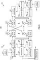
- FIG. 1 shows an example wireless communication system 100 deployed in a multi-story/multi-unit apartment or office building 101.
- the system 100 includes a macro base station 102 outside of the building 101 that can provide one or more UEs 114 with access to a wireless network.
- the system 100 also includes a plurality of small cells 104, 106, 110, located at various points inside the building 101.
- the UE 114 located inside one of the building units is configured to communicate with one or more of the small cells 104, 106, 110, and/or with the macro base station 102 to receive wireless access to a mobile network (not shown).
- Each small cell 104, 106, 110 may be configured to communicate via (e.g., transmit or receive signals on) one or more radio frequency channels. Moreover, the small cells 104, 106, 110 may be configured to communicate with one another and/or with other access points (e.g., macro base station 102) over one or more wired or wireless backhaul links. For example, the small cells 104, 106, 110 may communicate over the backhaul interface using an X2 interface. When multiple radio frequency (RF) channels (and/or bands) are available, conventionally configured small cells may be configured to select an operating channel by measuring the signal strengths of surrounding small cells, macro cells, or other nodes on one or more of the channels.
- RF radio frequency
- small cell 106 may be configured to choose a channel having a lowest signal strength measured by a NLM at the small cell 106, such to avoid interference from nodes producing the measured signal strength.
- the small cell is typically configured to maintain the selected channel until powered down or a configured reselection time. In some examples, a half-day or more may elapse before channel reselection.
- the foregoing channel selection based on measurements at the small cell location. As shown in FIG. 1 , the UE 114 may not be located at the same physical location as a given small cell serving the UE 114 (e.g., small cell 106). Accordingly, the network conditions at the position of the UE 114 may be different than the conditions at the small cell 106.
- small cell 106 (and/or any of the other small cells shown in FIG. 1 ) may be advantageously configured to select an operating channel based on information from UEs being served by the small cell 106.
- small cell 106 may include a communicating component 221 operable for determining to select an operating channel based on received measurement reports, modifying active and/or idle mode communication parameters to cause active and/or idle mode UEs to handover/reselect, switching to a selected operating channel, etc.
- UE 114 can transmit measurement reports to its serving cell (small cell 106 in this example) as part of evaluating neighboring cells for connected mode handover.
- the UE 114 may be configured to transmit a measurement report indicating signal strength or quality of the serving cell on the operating channel, strength or quality of signals received from neighboring cells on other operating channels, etc. Based on measurement reports received from the served UEs, small cell 106 may determine an operating channel that mitigates interference to the served UEs. Thus, the selection of the operating channel may consider network conditions experienced by the served UEs 114 in addition or alternatively to network conditions at the NLM of the small cell 106.
- Interference experienced by served UEs 114 can be dynamic based on movement of the UEs 114, activation/deactivation of neighboring cells (e.g., small cells 104, 110), other changes in network deployment, etc. Accordingly, DL/UL metrics can be measured and/or received by the small cell 106 to determine whether to evaluate other operating channels for possible switching, and the measurement reports received from the UEs 114 are used to determine an optimal operating channel. Thus, allowing dynamic operating channel selection by small cell 106 can allow the operating channel to change based on different interference conditions at the served UEs 114 (rather than at small cell 106).
- small cell 106 when switching operating channels, small cell 106 can cause connected mode UEs 114 to handover to neighboring cells and can cause idle mode UEs 114 to reselect to neighboring cells to minimize impact of the operating channel switch on the UEs 114.
- a persistence delay may be configured at the small cell 106 such to avoid frequent operating channel switching, and thus frequent handover/reselection of UEs 114.
- small cell 106 may be configured to manage automatic neighbor relations (ANR) based on the received UE 114 measurement reports. For example, small cell 106 can be configured to maintain a neighbor list of neighboring cells for provisioning to one or more other served UEs, where the neighbor list is maintained based at least in part on the measurement reports from the UEs 114. Similarly, small cell 106 may utilize the measurement reports from UEs 114 to determine availability of neighboring cells for handover (e.g., for switching of the operating channel of small cell 106 or otherwise), or other capabilities of the neighboring cells (e.g., X2 interface capabilities).
- ANR automatic neighbor relations
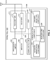
- FIG. 2 illustrates a small cell 106 for performing operating channel selection in a wireless network.
- Small cell 106 may be or may include substantially any of the apparatuses or devices described herein, such as small cells 104, 110 ( FIG. 1 ), apparatus 504 ( FIG. 5 ), small cells 710A, 710B ( FIG. 7 ), wireless device 910 ( FIG. 9 ), apparatus 1000 ( FIG. 10 ), etc.
- Small cell 106 may include a processor 204 for controlling operation of the small cell 106.
- Processor 204 may also be referred to as a central processing unit (CPU).
- Memory 206 which may include both read-only memory (ROM) and random access memory (RAM), may provide instructions and data to the processor 204.
- a portion of the memory 206 may also include non-volatile random access memory (NVRAM).
- NVRAM non-volatile random access memory
- Processor 204 typically performs logical and arithmetic operations based on program instructions stored within the memory 206.
- the instructions in the memory 206 may be executable to perform certain functions described herein.
- Processor 204 may comprise or be a component of a processing system implemented with one or more processors.
- the one or more processors may be implemented with any combination of general-purpose microprocessors, microcontrollers, digital signal processors (DSPs), field programmable gate array (FPGAs), programmable logic devices (PLDs), controllers, state machines, gated logic, discrete hardware components, dedicated hardware finite state machines, or any other suitable entities that can perform calculations or other manipulations of information.
- DSPs digital signal processors
- FPGAs field programmable gate array
- PLDs programmable logic devices
- controllers state machines, gated logic, discrete hardware components, dedicated hardware finite state machines, or any other suitable entities that can perform calculations or other manipulations of information.
- the processing system may also include machine-readable media for storing software.
- Software shall be construed broadly to mean any type of instructions, whether referred to as software, firmware, middleware, microcode, hardware description language, or otherwise. Instructions may include code (e.g., in source code format, binary code format, executable code format, or any other suitable format of code). The instructions, when executed by the one or more processors, cause the processing system to perform the various methods described herein.
- Small cell 106 may also include a housing 208 that may include a transmitter 210 and/or a receiver 212 to allow transmission and reception of data between the small cell 106 and a remote network node such as UE 114 ( FIG. 1 ).
- Transmitter 210 and receiver 212 may be combined into a transceiver 214.
- An antenna 216 may be attached to the housing 208 and electrically coupled to the transceiver 214 to facilitate transmitting and receiving signals.
- Small cell 106 may also include (not shown) multiple transmitters, multiple receivers, multiple transceivers, and/or multiple antennas.
- Small cell 106 may also include a signal detector 218 that may be used to detect and quantify the level of signals received by the transceiver 214. Signal detector 218 may detect such signals as total energy, energy per subcarrier per symbol, power spectral density and other signals. Small cell 106 may also include a digital signal processor (DSP) 220 for use in processing signals. The DSP 220 may be configured to generate a packet for transmission.
- DSP digital signal processor
- Small cell 106 may also include a communicating component 221 operable for determining to select an operating channel based on received measurement reports, modifying active and/or idle mode communication parameters to cause active and/or idle mode UEs to handover/reselect, switching to a selected operating channel, etc.
- communicating component 221 can include a network monitoring component 222.
- Network monitoring component 222 can be configured to receive certain DL quality metrics from served UEs 114 (e.g., via signals from the UEs 114 received by receiver 212) and/or measure certain UL quality metrics from signals received from served UEs 114.
- Network monitoring component 222 can accordingly determine whether an interference condition exists for the one or more served UEs 114 such to determine whether to switch to a different operating frequency.
- Network monitoring component 222 can be configured to obtain quality metrics relating to radio conditions over one or more channels for selecting an operating channel for small cell 106.
- the quality metrics can include strengths/qualities of a channel including received signal strength indicator (RSSI), reference signal received power (RSRP), reference signal received quality (RSRQ), etc., configuration parameters indicative of signals strength/quality including uplink modulation coding scheme (MCS), power headroom report (PHR), uplink block error rate (BLER), channel quality indicator (CQI), downlink MCS, etc.
- Network monitoring component 222 can also be configured to receive measurement reports from one or more UEs (e.g., as part of a handover procedure), as described further herein, receive signals from an NLM located at or accessible by small cell 106, and/or the like.
- Communicating component 221 may also include a channel selecting component 224.
- Channel selecting component 224 can be configured to select an operating channel for small cell 106.
- Channel selecting component 224 may select the operating channel based on received or measured DL/UL quality metrics, measurement reports received from served UEs 114, etc.
- channel selecting component 224 may aggregate measurement reports received from served UEs 114 to identify statistically significant quality indicators. Based on a comparison of a statistically significant quality indicator with a threshold quality, for example, channel selecting component 224 may determine that a new operating channel should be selected (e.g., where quality of a current operating channel is below a threshold quality and/or where quality of another operating channel achieves a threshold quality).
- Statistical significance and/or the threshold quality may be configured at small cell 106 (e.g., based on an OAM configuration message, a configuration stored in memory 206, etc.).
- the channel selecting component 224 may be further configured to identify the new operating channel for switching based on the measurement reports.
- a list of available channels may be maintained by small cell 106, such as in the memory 206, which may be determined from various measurement reports, received from an OAM, etc. Based on the received measurement reports, the list of available channels may be sorted (e.g., based on downlink quality indicated or otherwise inferred from the measurement reports, or other configured metric that can be received and/or determined at least based on the measurement reports) for determining an optimal operating channel.
- Communicating component 221 may also include a UE migrating component 226 to transition served UEs 114 to other serving cells based on channel selecting component 224 determining to select a new operating channel for small cell 106.
- UE migrating component 226 may be configured to transmit a message to the UEs served by small cell 106. The message may cause one or more of the plurality of served UEs to disconnect from the small cell 106.
- UE migrating component 226 may be configured to initiate handover of served UEs 114 in connected mode to neighboring cells.
- the message transmitted to the served UEs 114 may indicate that the UE 114 is to handover to the other neighboring cell.
- UE migrating component 226 may be further configured to negotiate or otherwise initiate handover with the neighboring cell (e.g., using X2 communications).
- UE migrating component 226 may be configured to modify system parameters of small cell 106 to trigger events at the UEs 114 that cause the UEs to handover to neighboring cells.
- UE migrating component 226 may modify one or more parameters of small cell 106 related to triggering inter-frequency or intra-frequency A3, A4, or A5 events (see Table 1 below), which are configured to the served UEs 114, to result in a more frequent or immediate triggering of an A3, A4, and/or A5 event.
- the modified parameters can be sent to the UEs 114 in one or more broadcast messages (e.g., system information block (SIB messages) or dedicated messages.
- SIB messages system information block
- the served UEs 114 may receive the parameters and trigger event(s) A3, A4, or A5 based on received parameters of the small cell 106, which can cause the UEs 114 to measure neighboring cells for handover, and send corresponding measurement reports to small cell 106 (which may then make a handover decision for the UEs 114).
- UE migrating component 226 may be configured to initiate idle mode reselection of UEs 114 camped on small cell 106.
- UE migrating component 226 may be configured to transmit a message causing idle mode UEs (also referred to herein as "camped UEs") to perform reselection to neighboring cells.
- the message can relate to a broadcast message (e.g., SIB messages) or dedicated message that include modified parameters to be configured at the UEs 114 for determining when to perform idle mode reselection.
- the modified parameters may relate to a hysteresis parameter that specifies a period of time to wait between determining whether to perform reselection, an offset parameter that specifies a period of time after which to determine whether to perform reselection, channel priority parameters related to a priority of one or more channels for camping, and/or the like.
- UE migrating component 226 may adjust or modify a value of one or more of these parameters, which causes reconfiguration at idle mode UEs upon receipt of the broadcast or dedicated message, thereby causing more definite and/or immediate (e.g., relatively faster by reducing the period of time) idle mode reselecting performed by the idle mode UEs 114 camped on the small cell 106.
- the various components of the small cell 106 may be coupled together by a bus system 228.
- the bus system 228 may include a data bus, for example, as well as a power bus, a control signal bus, and a status signal bus in addition to the data bus.
- a data bus for example, as well as a power bus, a control signal bus, and a status signal bus in addition to the data bus.
- Those of skill in the art will appreciate the components of the small cell 106 may be coupled together or accept or provide inputs to each other using some other mechanism.
- processor 204 may be used to implement not only the functionality described above with respect to the processor 204, but also to implement the functionality described above with respect to the signal detector 218 and/or the DSP 220, network monitoring component 222, channel selecting component 224, UE migrating component 226, etc. Further, each of the components illustrated in FIG. 2 may be implemented using a plurality of separate elements.
- channel selection at the small cell 106 may begin when the small cell 106 powers up.
- Channel selecting component 224 may be configured to download a channel list from an OAM node (not shown) that indicates available operating channels for the small cell 106.
- Channel selecting component 224 may then be configured to perform an initial channel selection to select one of the channels from the list as an operating channel.
- an NLM (not shown) at the small cell 106 may be utilized to measure signals received over at least a portion of the channels in the list, and channel selecting component 224 can initially select a channel having the lowest RSSI or other measure of signal strength or interference as the operating channel for the small cell 106.
- network monitoring component 222 may be configured to periodically evaluate the uplink (UL) and/or downlink (DL) metrics reported by UEs 114 served by small cell 106.
- a UE 114 operating in connected mode may periodically provide DL channel quality metrics (e.g., in channel state information (CSI) feedback, such as CQI reports).
- Network monitoring component 222 may evaluate the DL channel quality metrics to determine whether an interference condition exists at one or more UEs 114 on the current operating channel, which may cause channel selecting component 224 to determine whether to switch to a different operating channel (e.g., where the DL channel quality metrics are below a threshold).
- CSI channel state information
- network monitoring component 222 may determine whether there are statistical distributions of DL quality metrics reported by the served UEs 114 that are below a threshold, and if so there could be a potential need for a new operating channel selection.
- network monitoring component 222 can determine one or more UL channel quality metrics (e.g., UL MCS, PHR, UL BLER, etc.) based on communications received from the served UEs 114, which can be evaluated to determine whether channel selecting component 224 should consider switching operating channels (e.g., where the UL channel quality metrics are below a threshold).
- UL channel quality metrics e.g., UL MCS, PHR, UL BLER, etc.
- Network monitoring component 222 may determine the various thresholds for identifying interference conditions based at least in part on thresholds configured by an OAM, observed thresholds resulting in selection of an optimal operating channel for a certain period of time, simulation studies, network performance counters, etc. In some examples, network monitoring component 222 may generate the thresholds based on determining a density of the small cell deployment (e.g., based on measurement reports from served UEs 114, communications received from small cells in the deployment over an X2 interface, etc.).
- network monitoring component 222 may determine the thresholds as high percentile values of metrics received over a period of time or for a certain number of received metrics (e.g., 95th, 98th, etc. percentile values).
- network monitoring component 222 may be configured to analyze intra- and inter-frequency neighbor signal strength values reported by the served UEs 114 (e.g., RSSI, RSRP, RSRQ, etc.) to determine whether another operating channel may provide improved interference conditions for one or more of the UEs 114. For example, network monitoring component 222 may receive the measurement reports from the served UEs 114 as part of a handover procedure. The measurement reports may include metrics utilized to assess the strength (RSSI, RSRP, etc.) and/or quality (RSRQ) of the neighboring cells, and may be sorted in order of suitability (e.g., lowest RSSI/RSRP/RSRQ).
- RSSI strength
- RSRP quality
- signal strength may include such strength and/or quality measurements.
- measurement reports from the served UEs 114 may also be used by network monitoring component 222 to refine and manage automatic neighbor relations (ANR) as described above, such to define neighbor lists for the small cell 106 based on the UE measurements instead of or in addition to NLM measurements or OAM configurations.
- ANR automatic neighbor relations
- Such neighbor lists may be communicated to served UEs for selecting neighboring cells for handover, for determining parameters of the neighboring cells (e.g., backhaul interface parameters), and/or the like.
- network monitoring component 222 may modify event threshold parameters advertised in a broadcast message (e.g., a SIB message) or a dedicated message, such as an A(i) (e.g., A3, A4, A5) event threshold, which can cause UEs 114 retrieving and updating the parameters to trigger the associated events. Such events when triggered can cause the UEs 114 to generate and send measurement reports to small cell 106 (e.g., for the purposes of evaluating neighboring cells for handover).
- a broadcast message e.g., a SIB message
- A(i) e.g., A3, A4, A5
- channel selecting component 224 can determine whether to select a different operating channel based at least in part on the measurement reports received from one or more served UEs 114. For example, channel selecting component 224 can determine a channel for which a received signal strength reported by the UEs 114 (e.g. in total) is lowest, for which a received signal strength reported by the UEs 114 is lowest on average, for which a received signal strength reported by all served UEs 114 does not exceed a threshold, etc. In one example, network monitoring component 222 may rank the channels based on reported signal strength. In any case, channel selecting component 224 can accordingly select a different channel to be the operating channel for the small cell 106 where the different channel has more desirable radio conditions (e.g., lower reported signal strength) than the current operating channel.
- a received signal strength reported by the UEs 114 e.g. in total
- network monitoring component 222 may rank the channels based on reported signal strength.
- channel selecting component 224 can accordingly select a different channel to be the operating channel for
- UE migrating component 226 can attempt to cause the served UEs 114, in both idle and connected modes, to migrate to neighboring cells or otherwise not attempt to access small cell 106 while the small cell 106 switches to the selected operating channel. For example, UE migrating component 226 can handover connected mode UEs 114 to one or more neighboring cells and/or can cause idle mode UEs 114 to perform idle mode reselection to one or more neighboring cells. For example, UE migrating component 226 may be configured to determine whether the small cell 106 has a connection (e.g., an X2 connection) with any neighboring cells (not shown) such to negotiate handover of one or more connected mode UEs 114.
- a connection e.g., an X2 connection
- UE migrating component 226 may be configured to negotiate with intra/inter-frequency neighbor cells over the X2 interface and force network-initiated intra/inter-frequency handover of one or more connected mode UEs 114. Intra-frequency handover may be preferred where intra-frequency neighboring cells are present.
- UE migrating component 226 can cause handover of connected mode UEs 114 based at least in part on modifying system parameters sent to UEs in a broadcast message (e.g., a SIB message) or a dedicated message, such as parameters related to triggering A3, A4, A5 events at the UE for sending measurement reports and facilitating intra/inter-frequency handover of the UEs.
- a broadcast message e.g., a SIB message
- a dedicated message such as parameters related to triggering A3, A4, A5 events at the UE for sending measurement reports and facilitating intra/inter-frequency handover of the UEs.
- intra-frequency handover may be preferred where intra-frequency neighboring cells are present.
- UE migrating component 226 may be configured to modify hysteresis, offset parameters, and/or channel priority parameters broadcasted to idle mode UEs 114 to cause the idle mode UEs 114 to reselect to other neighboring cells. For example, UE migrating component 226 can decrease the hysteresis and/or offset parameters so that the idle mode UEs 114 can attempt reselection sooner than with the previously configured parameters. Furthermore, for example, UE migrating component 226 can decrease the channel priority parameters to make the small cell 106 operating channel less desirable, such to cause idle mode UEs 114 to reselect a neighboring cell that uses a different operating channel in the next reselection opportunity.
- UE migrating component 226 may increase the channel priority of the operating channel to which the small cell 106 plans to switch.
- Channel selecting component 224 may be configured to switch to the selected channel based on UE migrating component 226 causing migration of the connected and/or idle mode UEs 114. In one example, channel selecting component 224 may begin switching to the selected channel once the connected mode UEs 114 are handed over and regardless of the idle mode UEs 114. Switching to the selected channel, in this regard, may include switching the transmitter 210 and/or receiver 212 to operate on the selected channel.
- channel selecting component 224 may be configured with a persistence delay (e.g., from an OAM, a configuration stored in memory, etc.). Accordingly, in one example, the persistence delay may relate to a timer value, and upon switching to the selected channel, channel selecting component 224 may initialize a timer using the persistence delay timer value such that a subsequent channel selection may not occur until after expiration of the timer. In some examples, network monitoring component 222 can also be configured to refrain from monitoring the DL/UL metrics for the purposes of determining whether a new channel should be selected until after expiration of the timer to conserve resources.
- a persistence delay e.g., from an OAM, a configuration stored in memory, etc.
- the persistence delay may relate to a timer value
- channel selecting component 224 may initialize a timer using the persistence delay timer value such that a subsequent channel selection may not occur until after expiration of the timer.
- network monitoring component 222 can also be configured to refrain from monitoring the DL/UL metrics for the purposes of determining
- the configured persistence delay may relate to a number of interference conditions and/or a severity of interference conditions that are to be detected by the network monitoring component 222 until selection to a different operating channel can be performed.
- the persistence delay may be set based at least in part on interference experienced by the UEs 114 (e.g., in previous operating channel selections), small cell deployment characteristics (e.g., a number of small cells within a proximity of small cell 106), etc., and may be configured by the channel selecting component 224 based on observing such interference or characteristics, by an OAM, and/or the like.
- FIGs. 3 and 4A-4C methods that may be performed by the apparatuses described herein (e.g., small cell 106, apparatus 504, small cells 710A, 710B, wireless device 910, apparatus 1000, etc.) are depicted.
- the operations described below in FIGs. 3 and 4A-4C are presented in a particular order and/or as being performed by an example component, it should be understood that the ordering of the actions and the components performing the actions may be varied, depending on the implementation.
- a component may be one of the parts that make up a system, may be hardware or software, and/or may be divided into other components.
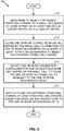
- FIG. 3 illustrates an example method 300 for switching operating channels at a small cell in wireless communications.
- Method 300 includes, at Block 310, determining to select a different operating channel at a small cell based at least in part on at least one of a DL quality metric or a UL quality metric.
- Channel selecting component 224 FIG. 2
- network monitoring component 222 can measure the DL and/or UL quality metric as reported by or measured for one or more UEs 114, and can accordingly determine whether an interference condition exists at the one or more UEs 114, and thus, whether to select a different operating channel.
- the DL quality metric can relate to CQI or other measures of channel quality reported by the UEs 114
- the UL metric may relate to MCS, PHR, BLER, etc. selected or measured for the UEs 114.
- determining whether the interference condition exists may relate to comparing the at least one of the DL quality metric or the UL quality metric to one or more thresholds, which may be selected based on a statistics distribution of the quality metrics, to determine whether the interference condition exists.
- determining to select the different operating channel may be based at least in part on determining whether a persistence delay is satisfied (e.g., whether a persistence timer is expired, a number of interference conditions has occurred, or other events related to a configured persistence delay).
- channel selecting component 224 can determine the different operating channel based at least in part on evaluating measurement reports received form one or more UEs 114 to determine an operating channel that has a lowest reported signal strength, or that would otherwise cause the lowest interference to the one or more UEs 114. For example, channel selecting component 224 may select the operating channel with the lowest average reported signal strength (e.g., RSSI, RSRP, RSRQ, etc.), the operating channel for which none of the UEs 114 report a signal strength over a certain threshold, an operating channel for which no more than a threshold number of UEs 114 report signal strength over the certain threshold, etc. In some examples, channel selecting component 224 may determine that the current operating channel is the most desirable based on the measurement reports received from the UEs, in which case channel selecting component 224 may determine not to select a different operating channel at Block 310.
- the lowest average reported signal strength e.g., RSSI, RSRP, RSRQ, etc.
- channel selecting component 224 may determine that the current operating channel
- Method 300 also includes, at Block 312, causing one or more connected mode UEs served by the small cell to handover to one or more neighboring cells based at least in part on determining to select the different operating channel.
- UE migrating component 226 can cause the one or more connected mode UEs served by the small cell 106 to handover to one or more neighboring cells based at least in part on channel selecting component 224 determining to select the different operating channel.
- UE migrating component 226 can cause the one or more connected mode UEs to handover by negotiating handover with the one or more neighboring cells (e.g., over an X2 interface), by adjusting parameters broadcasted (e.g. in a SIB message) to the UEs for triggering events related to generating measurement reports for facilitating intra-/inter-frequency handover, and/or the like.
- Method 300 also includes, at Block 314, modifying one or more parameters configured for one or more idle mode UEs camped on the small cell to cause the one or more idle mode UEs to reselect to the one or more neighboring cells.
- UE migrating component 226 can modify the one or more parameters configured to the one or more idle mode UEs camped on the small cell to cause the one or more idle mode UEs to reselect to the one or more neighboring cells.
- UE migrating component 226 can modify a hysteresis, offset, channel priority, or similar parameter in an attempt to effectuate idle mode reselection by the one or more idle mode UEs camped on small cell 106.
- Modifying the one or more parameters configured for one or more idle mode UEs may also be based at least in part on determining to select the different operating channel.
- Method 300 further includes, at Block 316, switching to use the different operating channel at least when the one or more connected mode UEs are handed over to the one or more neighboring cells.
- Channel selecting component 224 can switch to use the different operating channel at least when the one or more connected mode UEs are handed over to the one or more neighboring cells. This may include channel selecting component 224 determining whether all or at least a threshold number of connected mode UEs are handed over. In addition, for example, channel selecting component 224 may not determine whether any or some of the idle mode UEs have reselected before determining to switch the operating channel. For example, channel selecting component 224 can switch the operating channel for transmitter 210, receiver 212, etc.
- FIGs. 4A , 4B , and 4C collectively depict a flow diagram of an example method of small cell channel selection based on UE reports.
- the process shown in FIGs. 4A , 4B , and 4C may be implemented in whole or in part by small cell 106 or other devices described herein.
- the method begins at Block 402.
- the start of the method at Block 402 can generally correspond to a powering on or reset of at least one small cell.
- a plurality of small cells may be deployed (see FIG. 1 ).
- a cell can optionally be selected for channel selection.
- the selection may be based on a token passed among small cells as each small cell completes the channel selection process.
- the selection at Block 404 may be based on a configured time, interval, etc. allocated to a given small cell for channel selection.
- the small cells may be configured to coordinate timing for performing channel selection through associated neighbor management messaging, backhaul messaging, or via a centralized network node.
- channel selecting component 224 can be configured to perform one or more of these functions to determine whether to evaluate other operating channels.
- Method 400 includes, at Block 406, making an initial channel selection of a least used operating channel using a NLM or based on an OAM database.
- Channel selecting component 224 may make the initial channel selection of the least used operating channel, as described, based on using an NLM to measure the channels (e.g., and selecting a channel with the lowest measured signal strength), based on determining a number and/or location/distance of neighboring cells using certain channel frequencies (e.g., and selecting a channel not used by any or at least a threshold number of neighboring cells, or a channel at least not used by neighboring cells within a threshold distance of small cell 106), etc.
- the small cell 106 can begin advertising service on the selected channel.
- UEs 114 may accordingly receive signals advertising the service, and may connect to the small cell 106.
- UEs 114 may perform periodic measurement reporting to facilitate considering neighboring cells for handover when radio conditions with the small cell 106 degrade.
- the 3GPP specification provides a standardized measurement, format, timing, and triggering requirements for connected UEs to report neighboring cell measurements.
- DL and UL quality metrics reported by or measured for the connected mode UEs can be periodically evaluated.
- Network monitoring component 222 may evaluate the reported or measured DL and UL quality metrics, as described.
- Network monitoring component 222 may receive the reported DL quality metrics from the UEs 114 (e.g., as RSSI, RSRP, RSRQ, CQI or other quality reports), and specified DL MCS, etc., and/or may determine the UL quality metrics based at least in part on MCS, PHR, BLER, etc. for the UEs 114.
- Network monitoring component 222 may determine whether the Nth percentile of the DL quality metrics (RSRQ, CQI, DL MCS, etc.) are less than one or more threshold, which may indicate an interference condition. For example, network monitoring component 222 may determine this at least in part by aggregating DL quality metric values from CSI reports from one or more of the UEs 114, measurement reports, etc. to determine if the metric is statistically significant. As shown in FIG.
- a top Nth percentile value of the metrics may be used as one basis for the determination by network monitoring component 222 at Block 410.
- the threshold may be provided via an OAM configuration message, configured in a memory accessible by the small cell, dynamically configured via a configuration interface, received over the air, or through backhaul signaling from other cells, etc.
- the method includes, at Block 412, similarly determining whether Nth percentile of the UL quality metrics (MCS, PHR, etc.) are less than one or more thresholds.
- Network monitoring component 222 can determine whether Nth percentile of the UL quality metrics (MCS, PHR, etc.) are less than one or more thresholds.
- network monitoring component 222 can include considering both uplink and downlink performance when deciding whether channel selection is appropriate.
- the method returns to Block 408 to continue the periodic evaluation. If, at Block 410, the Nth percentile of the DL quality metrics (RSRQ, CQI, DL MCS, etc.) are less than one or more thresholds, or, at Block 412, the UL quality metrics (MCS, PHR, etc.) are less than one or more thresholds, then an interference condition may exist, and the method proceeds to Block 414 in FIG. 4B for consideration of a new operating channel. For example, channel selecting component 224 can consider whether to select a new operating channel based on network monitoring component 222 determining that the interference condition exists, as described above.
- Intra/inter-frequency events A1-A5
- Network monitoring component 222 can determine whether the intra/inter-frequency events are reported by the connected mode UEs 114. Such events, as described, can cause generation of measurement reports at the UEs, which can indicate signal strength (and thus interference) detected over various channels by the UEs. Thus, these measurement reports may be desired for determining whether to switch operating channels (e.g., where other operating channels are reported to have low signal strengths at the UEs 114).
- intra/inter-frequency events (A1-A5) are not reported by the UEs (or not reported by a threshold number or percentage of connected mode UEs)
- A1, A2, or A3 parameters may be modified to facilitate intra/inter-frequency measurements.
- Network monitoring component 222 may modify these parameters in a broadcast message (e.g., SIB message), dedicated message, etc., to one or more connected mode UEs to cause the UEs to generate measurement reports.
- the method may return to Block 416 to determine whether the reports have been received.
- the method also includes, at block 420 (after either determining intra/inter-frequency events have been reported on by the UEs at Block 416 or after modifying parameters to facilitate such reporting at Block 418), determining whether to change the operating channel.
- Channel selecting component 224 can determine whether to change the operating channel, as described, based at least in part on determining whether one or more channels from the measurement reports are more desirable than the current operating channel (e.g., have a lower average reported signal strength, have a lower reported signal strength for at least a threshold number or percentage of served UEs 114, have no or less than a threshold number of reported signal strengths from the UEs 114 that are over a threshold, etc.).
- channel selecting component 224 may sort the available channels based on such measurements of signal strength.
- the sort order may be determined by a configuration for the serving node such as OAM configuration.
- the channels may be sorted based on one or more signal strength measurements.
- the sorting provides an ordered list of channels available to the small cell 106, ordered by relative signal strength (e.g., interference). If the highest quality channel is the current channel, no change is identified and the method can return to Block 408 of FIG. 4A at Block 421. If the optimal operating channel is not the current operating channel, it can be determined, at Block 420 to change the operating channel.
- UE migrating component 226 can determine whether the X2 interface is available with one or more neighboring cells for negotiating handover of connected mode UEs.
- X2 is an example of a communication protocol allowing cells in a wireless network nodes to exchange messages (e.g. to facilitate handover or other functions). It is to be appreciated that other protocols facilitating communications between cells can be used in this example.
- Some small-cell networks include nodes which all have X2 capabilities. Some small cells or neighboring cells, however, may not have an X2 interface.
- intra/inter-frequency neighbor cells can be negotiated with over X2 to cause network initiated intra/inter-frequency handover of connected mode UEs.
- UE migrating component 226 can negotiate with the intra/inter-frequency neighbor cells over X2 to cause the network initiated intra/inter-frequency handover of the connected mode UEs. As described, UE migrating component 226 may prefer to perform intra-frequency handover where intra-frequency neighboring cells are reported in the measurement reports from the connected mode UEs 114.
- intra/inter-frequency A3, A4, A5 parameters can be modified for the UEs to trigger the events, which facilitate intra/inter-frequency handover of connected mode UEs.
- UE migrating component 226 can modify the intra/inter-frequency A3, A4, A5 parameters for the UEs to trigger the events that facilitate intra/inter-frequency handover of connected mode UEs.
- intra/inter-frequency A3, A4, or A5 parameters e.g., cell specific offset to neighbor cell (Ocn)
- Ocn cell specific offset to neighbor cell
- a connected UE may trigger a corresponding A3, A4, or A5 event, thus initiating inter or intra frequency handover.
- UE migrating component 226 and/or the UEs may be configured to prefer intra-frequency handover.
- A1-A5 events that are detectable at the UE may be summarized as follows, and may have the following tunable parameters (e.g., that may be modified by UE migrating component 226 as described herein) in some wireless communication technologies (e.g., LTE): TABLE 1 Event Summary Tunable parameters A1 Serving cell signal becomes better than a threshold Serving cell reference signal received power (RSRP), reference signal received quality (RSRQ) A2 Serving cell signal becomes worse than a threshold Serving cell RSRP, RSRQ A3 Neighbor cell signal becomes offset better than the serving cell signal Ofn, Ofs, Ocn, Ocs, Hys, Off, timeToTrigger A4 Neighbor cell signal becomes better than threshold Ofn, Ocn, Hys, Thresh, Off, timeToTrigger A5 Serving cell signal becomes worse than threshold1 and neighbour cell signal becomes better than threshold2 Ofn, Ocn, Hys, Thresh1, Thresh2, Off, timeToTrigger where Ofn is the frequency specific offset of
- UE migrating component 226 may determine whether there are any more connected mode UEs in the small cell 106. If so, at Block 430, it may optionally be determined whether the number of connected mode UEs is less than a threshold. UE migrating component 226 may optionally determine whether the number of connected mode UEs is less than a threshold. If not, the method can proceed to Block 422 to again attempt to cause handover of the connected mode UEs.
- Block 428 If, at Block 428, there are no more connected mode UEs at the small cell, or, at Block 430, the number of connected mode UEs is less than a threshold, the process continues to FIG. 4C via Block 432.
- a threshold number/percentage of UEs or any UEs depending on the deployment. For example, in a residential home setting, it may be acceptable to drop less UEs than in an enterprise deployment.
- the threshold number/percentage of UEs for use in Block 430 may be configured (e.g., by an OAM), determined based on a number of historically served devices, and/or the like.
- hysteresis, offset, or channel priority parameters may be modified to facilitate intra/inter-frequency reselection of camped UEs to neighbor cells.
- UE migrating component 226 may modify the hysteresis, offset, or channel priority parameters, as described, to facilitate the intra/inter-frequency reselection of the camped UEs to neighbor cells.
- small cell 106 can advertise the modified parameters in one or more broadcast messages (e.g., a SIB message), dedicated messages, and/or the like, for consumption and updating/using by UEs to determine when and under what circumstances to perform reselection.
- broadcast messages e.g., a SIB message
- dedicated messages e.g., dedicated messages, and/or the like
- a transition can occur to re-synchronize to a highest ranked inter-frequency operating channel.
- Channel selecting component 224 can transition to re-synchronize to the highest ranked inter-frequency operating channel (e.g., the operating channel with the lowest reported signal strengths from the UEs, as described above).
- Channel selecting component 224 can determine whether the persistence delay is satisfied before determining whether to evaluate operating channels for switching. For example, determining whether the persistence delay is satisfied can relate to determining whether a persistence timer, which can be set when transitioning to the new operating channel at Block 436, has expired. In another example, determining whether the persistence delay is satisfied may include determining whether a number of interference conditions have occurred since transitioning operating channels at Block 436.
- the method can proceed back to starting Block 402 in FIG. 4A via Block 440. It is to be appreciated that during the method shown in FIGS. 4A , 4B , and 4C additional measurements reports from devices may be received. These additional reports may be used in subsequent iterations of the channel selection process. In some examples, the process may be configured to consider reports received since a previous operating channel selection, a configured number of reports, or reports from a configured range of time (e.g., last hour, last day, last n minutes, etc.), and/or the like.
- FIG. 5 illustrates several sample components (represented by corresponding blocks) that may be incorporated into an apparatus 502, an apparatus 504, and an apparatus 506 (e.g., corresponding to an access terminal, an access point, and a network entity, respectively) to support signal processing operations as taught herein.
- these components may be implemented in different types of apparatuses in different examples (e.g., in an ASIC, in a system on chip (SoC), etc.).
- the described components also may be incorporated into other apparatuses in a communication system.
- other apparatuses in a system may include components similar to those described with reference to small cell 106 and associated example methods in FIGs. 2 , 3 , and 4A-4C to provide similar functionality.
- apparatus 504 can include a small cell 106 that communicates with UEs (e.g., apparatus 502) and network entities (e.g., network entity 508, which may include an OAM and/or other small cells).
- UEs e.g., apparatus 502
- network entities e.g., network entity 508, which may include an OAM and/or other small cells.
- the network monitoring component 222, channel selecting component 224, UE migrating component 226, functions thereof, etc., as described above, Blocks 310-316 of method 300 in FIG. 3 , Blocks 402-440 of method 400 in FIGs. 4A-4C , etc., as described below, can be implemented by processor modules in processing system 534, in computer executable code or instructions stored in memory component 540 and executed by processing system 534, etc.
- apparatus 504 may include a communicating component 221 operable for determining to select an operating channel based on received measurement reports, modifying active and/or idle mode communication parameters to cause active and/or idle mode UEs to handover/reselect, switching to a selected operating channel, etc., as described above with reference to FIGs. 2 , 3 , and 4A-4C .
- communicating component 221 can communicate with or can be implemented by processing system 534, based on instructions in memory component 540, etc.
- the apparatus 502 and the apparatus 504 each include at least one wireless communication device (represented by the communication devices 508 and 514) for communicating with other nodes via at least one designated radio access technology.
- Each communication device 508 includes at least one transmitter (represented by the transmitter 510) for transmitting and encoding signals (e.g., messages, indications, information, and so on) and at least one receiver (represented by the receiver 512) for receiving and decoding signals (e.g., messages, indications, information, pilots, and so on).
- each communication device 514 includes at least one transmitter (represented by the transmitter 516) for transmitting signals (e.g., messages, indications, information, pilots, and so on) and at least one receiver (represented by the receiver 518) for receiving signals (e.g., messages, indications, information, and so on).
- signals e.g., messages, indications, information, pilots, and so on
- receiver 5148 for receiving signals (e.g., messages, indications, information, and so on).
- a transmitter and a receiver may comprise an integrated device (e.g., embodied as a transmitter circuit and a receiver circuit of a single communication device) in some examples, may comprise a separate transmitter device and a separate receiver device in some examples, or may be embodied in other ways in other examples.
- a wireless communication device e.g., one of multiple wireless communication devices of the apparatus 504 comprises a network listen module, as described.
- the apparatus 506 may include at least one communication device (represented by the communication device 526) for communicating with other nodes.
- the communication device 526 may comprise a network interface that is configured to communicate with one or more network entities via a wire-based or wireless backhaul.
- the communication device 526 may be implemented as a transceiver configured to support wire-based or wireless signal communication. This communication may involve, for example, sending and receiving: messages, parameters, or other types of information.
- the communication device 526 is shown as comprising a transmitter 528 and a receiver 530.
- communication device 520 may comprise a network interface that is configured to communicate with one or more network entities via a wire-based or wireless backhaul.
- the communication device 520 is shown as comprising a transmitter 522 and a receiver 524.
- the apparatuses 502, 504, and 506 also include other components that may be used in conjunction with signal processing operations as taught herein.
- the apparatus 502 includes a processing system 532 for providing functionality relating to, for example, communicating with an access point to support functions as taught herein and for providing other processing functionality.
- the apparatus 504 includes a processing system 534 for providing functionality relating to, for example, functions as taught herein and for providing other processing functionality.
- the apparatus 506 includes a processing system 536 for providing functionality relating to, for example, functions as taught herein and for providing other processing functionality.
- the apparatuses 502, 504, and 506 include memory devices 538, 540, and 542 (e.g., each including a memory device), respectively, for maintaining information (e.g., information indicative of reserved resources, thresholds, parameters, and so on).
- the apparatuses 502, 504, and 506 include user interface devices 544, 546, and 548, respectively, for providing indications (e.g., audible and/or visual indications) to a user and/or for receiving user input (e.g., upon user actuation of a sensing device such a keypad, a touch screen, a microphone, and so on).
- the apparatus 502 is shown in FIG. 5 as including components that may be used in the various examples described herein. In practice, the illustrated blocks may have different functionality in different aspects.
- the components of FIG. 5 may be implemented in various ways.
- the components of FIG. 5 may be implemented in one or more circuits such as, for example, one or more processors and/or one or more ASICs (which may include one or more processors).
- each circuit may use and/or incorporate at least one memory component for storing information or executable code used by the circuit to provide this functionality.
- some or all of the functionality represented by blocks 508, 532, 538, and 544 may be implemented by processor and memory component(s) of the apparatus 502 (e.g., by execution of appropriate code and/or by appropriate configuration of processor components).
- some or all of the functionality represented by blocks 514, 520, 534, 540, and 546 may be implemented by processor and memory component(s) of the apparatus 504 (e.g., by execution of appropriate code and/or by appropriate configuration of processor components). Also, some or all of the functionality represented by blocks 526, 536, 542, and 548 may be implemented by processor and memory component(s) of the apparatus 506 (e.g., by execution of appropriate code and/or by appropriate configuration of processor components).
- Some of the access points referred to herein may comprise small cells, as described, to provide voice and high speed data service for access terminals supporting cellular radio communication (e.g., CDMA, WCDMA, UMTS, LTE, etc.).
- cellular radio communication e.g., CDMA, WCDMA, UMTS, LTE, etc.
- Small cells may be configured to support different types of access modes. For example, in an open access mode, a small cell may allow any access terminal to obtain any type of service via the small cell. In a restricted (or closed) access mode, a small cell may only allow authorized access terminals to obtain service via the small cell. For example, a small cell may only allow access terminals (e.g., so called home access terminals) belonging to a certain subscriber group (e.g., a closed subscriber group (CSG)) to obtain service via the small cell. In a hybrid access mode, alien access terminals (e.g., non-home access terminals, non-CSG access terminals) may be given limited access to the small cell. For example, a macro access terminal that does not belong to a small cell's CSG may be allowed to access the small cell only if sufficient resources are available for all home access terminals currently being served by the small cell.
- an open access mode a small cell may allow any access terminal to obtain any type of service via the small cell.
- small cells operating in one or more of these access modes may be used to provide indoor coverage and/or extended outdoor coverage.
- small cells may provide improved service within the coverage area and potentially extend the service coverage area for users of a macro network.
- the teachings herein may be employed in a network that includes macro scale coverage (e.g., a large area cellular network such as a third generation (3G) network, typically referred to as a macro cell network or a WAN) and smaller scale coverage (e.g., a residence-based or building-based network environment, typically referred to as a LAN).
- macro scale coverage e.g., a large area cellular network such as a third generation (3G) network, typically referred to as a macro cell network or a WAN
- smaller scale coverage e.g., a residence-based or building-based network environment, typically referred to as a LAN.
- AT access terminal
- the access terminal may be served in certain locations by access points that provide macro coverage while the access terminal may be served at other locations by access points that provide smaller scale coverage.
- the smaller coverage nodes may be used to provide incremental capacity growth, in-building coverage, and different services (e.g., for a more robust user experience).
- a node e.g., an access point
- a node that provides coverage over a relatively large area may be referred to as a macro access point
- a node that provides coverage over a relatively small area e.g., a residence
- a small cell e.g., a small cell
- the teachings herein may be applicable to nodes associated with other types of coverage areas.
- a small cell may provide coverage (e.g., coverage within a commercial building) over an area that is smaller than a macro area.
- other terminology may be used to reference a macro access point, a small cell, or other access point-type nodes.
- a macro access point may be configured or referred to as an access node, base station, access point, eNodeB, macro cell, and so on.
- a node may be associated with (e.g., referred to as or divided into) one or more cells or sectors.
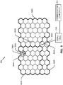
- FIG. 6 illustrates a wireless communication system 600, configured to support a number of users, in which the teachings herein may be implemented.
- the system 600 provides communication for multiple cells 602, such as, for example, macro cells 602A - 602G, with each cell being serviced by a corresponding access point 604 (e.g., access points 604A - 604G).
- access terminals 606 e.g., access terminals 606A - 606L
- Each access terminal 606 may communicate with one or more access points 604 on a forward link (FL) and/or a reverse link (RL) at a given moment, depending upon whether the access terminal 606 is active and whether it is in soft handoff, for example.
- the wireless communication system 600 may provide service over a large geographic region. For example, macro cells 602A - 602G may cover a few blocks in a neighborhood or several miles in a rural environment.
- access points 604 or some of the access terminals (e.g., access terminal 606A, 606H, 606J) may can include a small cell 106, and/or one or more components thereof (as described in FIG. 2 ) or functionalities associated therewith (e.g., as described in FIGs.
- access terminals 606A, 606H, and/or 606J may include a communicating component 221 operable for determining to select an operating channel based on received measurement reports, modifying active and/or idle mode communication parameters to cause active and/or idle mode UEs to handover/reselect, switching to a selected operating channel, etc., as described above in reference to FIG. 2 .
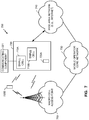
- FIG. 7 illustrates an example of a communication system 700 where one or more small cells operating according to one or more aspects described herein are deployed within a network environment.
- the system 700 includes multiple small cells (e.g., small cells 710A and 710B) installed in a relatively small scale network environment (e.g., in one or more user residences 730).
- the small cells 710A and/or 710B may include small cell 106, and thus may include one or more of the components thereof (described in FIG. 2 ) for performing functions associated therewith (e.g., as described in FIGs. 3 and 4A-4C ).
- small cells 710A and/or 710B may include a communicating component 221 operable for determining to select an operating channel based on received measurement reports, modifying active and/or idle mode communication parameters to cause active and/or idle mode UEs to handover/reselect, switching to a selected operating channel, etc., as described above in reference to FIGs. 2 , 3 , and 4A-4C .
- Each small cell may be coupled to a wide area network 740 (e.g., the Internet) and a mobile operator core network 750 via a DSL router, a cable modem, a wireless link, or other connectivity means (not shown).
- a wide area network 740 e.g., the Internet
- a mobile operator core network 750 via a DSL router, a cable modem, a wireless link, or other connectivity means (not shown).
- each small cell e.g., small cells 710A and 710B
- access to small cells may be restricted whereby a given access terminal may be served by a set of designated (e.g., home) small cell(s) but may not be served by any non-designated small cells (e.g., a neighbor's small cell).
- a set of designated (e.g., home) small cell(s) may not be served by any non-designated small cells (e.g., a neighbor's small cell).
- the owner of a small cell 710 may subscribe to mobile service, such as, for example, 3G mobile service, offered through the mobile operator core network 750.
- an access terminal 720 may be capable of operating both in macro environments and in smaller scale (e.g., residential) network environments. In other words, depending on the current location of the access terminal 720, the access terminal 720 may be served by a macro cell access point 760 associated with the mobile operator core network 750 or by any one of a set of small cells 710 (e.g., the small cells 710A and 710B that reside within a corresponding user residence 730).
- a small cell 710 may be backward compatible with legacy access terminals 720.
- a small cell 710 may be deployed on a single frequency or, in the alternative, on multiple frequencies.
- the single frequency or one or more of the multiple frequencies may overlap with one or more frequencies used by a macro access point (e.g., access point 760).
- an access terminal 720 may be configured to connect to a preferred small cell (e.g., the home small cell of the access terminal 720) whenever such connectivity is possible. For example, whenever the access terminal 720A is within the user's residence 730, it may be desired that the access terminal 720A communicate only with the home small cell 710A or 710B.
- a preferred small cell e.g., the home small cell of the access terminal 720
- the access terminal 720 may continue to search for the most preferred network (e.g., the preferred small cell 710) using a better system reselection (BSR) procedure, which may involve a periodic scanning of available systems to determine whether better systems are currently available and subsequently acquire such preferred systems.
- BSR system reselection
- the access terminal 720 may limit the search for specific band and channel. For example, one or more operating channels for the small cells may be defined whereby all small cells (or all restricted small cells) in a region operate on the operating channel(s). The search for the most preferred system may be repeated periodically.
- the access terminal 720 selects the small cell 710 and registers on it for use when within its coverage area.
- Access to a small cell may be restricted in some aspects.
- a given small cell may only provide certain services to certain access terminals.
- a given access terminal may only be served by the macro cell mobile network and a defined set of small cells (e.g., the small cells 710 that reside within the corresponding user residence 730).
- an access point may be restricted to not provide, for at least one node (e.g., access terminal), at least one of: signaling, data access, registration, paging, or service.
- a restricted small cell (which may also be referred to as a Closed Subscriber Group Home NodeB) is one that provides service to a restricted provisioned set of access terminals. This set may be temporarily or permanently extended as necessary.
- a Closed Subscriber Group (CSG) may be defined as the set of access points (e.g., small cells) that share a common access control list of access terminals.
- an open small cell may refer to a small cell with unrestricted access (e.g., the small cell allows access to any access terminal).
- a restricted small cell may refer to a small cell that is restricted in some manner (e.g., restricted for access and/or registration).
- a home small cell may refer to a small cell on which the access terminal is authorized to access and operate on (e.g., permanent access is provided for a defined set of one or more access terminals).
- a hybrid (or guest) small cell may refer to a small cell on which different access terminals are provided different levels of service (e.g., some access terminals may be allowed partial and/or temporary access while other access terminals may be allowed full access).
- An alien small cell may refer to a small cell on which the access terminal is not authorized to access or operate on, except for perhaps emergency situations (e.g., emergency-911 calls).
- a home access terminal may refer to an access terminal that is authorized to access the restricted small cell installed in the residence of that access terminal's owner (usually the home access terminal has permanent access to that small cell).
- a guest access terminal may refer to an access terminal with temporary access to the restricted small cell (e.g., limited based on deadline, time of use, bytes, connection count, or some other criterion or criteria).
- An alien access terminal may refer to an access terminal that does not have permission to access the restricted small cell, except for perhaps emergency situations, for example, such as 911 calls (e.g., an access terminal that does not have the credentials or permission to register with the restricted small cell).
- a pico access point may provide the same or similar functionality for a larger coverage area.
- a pico access point may be restricted, a home pico access point may be defined for a given access terminal, and so on.
- each terminal may communicate with one or more access points via transmissions on the forward and reverse links.
- the forward link refers to the communication link from the access points to the terminals
- the reverse link refers to the communication link from the terminals to the access points.
- This communication link may be established via a single-in-single-out system, a multiple-in-multiple-out (MIMO) system, or some other type of system.
- MIMO multiple-in-multiple-out
- a MIMO system employs multiple ( N T ) transmit antennas and multiple ( N R ) receive antennas for data transmission.
- a MIMO channel formed by the N T transmit and N R receive antennas may be decomposed into N S independent channels, which are also referred to as spatial channels, where N S ⁇ min ⁇ N T , N R ⁇ .
- Each of the N S independent channels corresponds to a dimension.
- the MIMO system may provide improved performance (e.g., higher throughput and/or greater reliability) if the additional dimensionalities created by the multiple transmit and receive antennas are utilized.
- a MIMO system may support time division duplex (TDD) and frequency division duplex (FDD).
- TDD time division duplex
- FDD frequency division duplex
- the forward and reverse link transmissions are on the same frequency region so that the reciprocity principle allows the estimation of the forward link channel from the reverse link channel. This enables the access point to extract transmit beam-forming gain on the forward link when multiple antennas are available at the access point.
- FIG. 8 illustrates an example of a coverage map 800 where several tracking areas (802A, 802B, and 802C) (or routing areas or location areas) are defined, each of which may include several macro coverage areas (804A and 804B), one or more of which may include one or more small cell coverage areas (806A, 806B, 806C, and 806D) serviced by one or more small cells operating according to one or more aspects described herein. Also, one or more small cell coverage areas may be defined within a given tracking area outside of a given macro coverage area. Specifically, areas of coverage associated with tracking areas 802A, 802B, and 802C are delineated by the wide lines and the macro coverage areas 804A and 804B are represented by the larger hexagons.
- the tracking areas 802A, 802B, and 802C may also include one or more small cell coverage areas 806A, 806B, 806C, and 806D.
- each of the small cell coverage areas e.g., small cell coverage areas 806B and 806C
- macro coverage areas e.g., macro coverage areas 804A and 804B
- some or all of a small cell coverage area might not lie within a macro coverage area 804.
- a large number of small cell coverage areas may be defined within a given tracking area or macro coverage area (e.g., 804A).
- small cell coverage areas 806B and 806C can be provided by a small cell, such as small cell 710A described above in FIG. 7 .
- small cell 710A can also include a communicating component 221 operable for determining to select an operating channel based on received measurement reports, modifying active and/or idle mode communication parameters to cause active and/or idle mode UEs to handover/reselect, switching to a selected operating channel, etc., as described above in reference to FIGs. 2 , 3 , and 4A-4C .
- FIG. 9 illustrates in more detail the components of a wireless device 910 (e.g., a small cell) and a wireless device 950 (e.g., a UE) of a sample communication system 900 that may be adapted as described herein.
- wireless device 910 can include a small cell 106, and thus may include components associated therewith as described in FIG. 2 for performing certain functions, such as those described in FIGs. 3 and 4A-4C .
- the network monitoring component 222, channel selecting component 224, UE migrating component 226, functions thereof, etc. as described above, Blocks 310-316 of method 300 in FIG. 3 , Blocks 402-440 of method 400 in FIGs.
- eNB 910 can include a communicating component 221 coupled to processor 930 (e.g., communicating with or implemented by the processor 930) and operable for determining to select an operating channel based on received measurement reports, modifying active and/or idle mode communication parameters to cause active and/or idle mode UEs to handover/reselect, switching to a selected operating channel, etc., as described above in reference to FIGs. 2 , 3 , and 4A-4C .
- traffic data for a number of data streams is provided from a data source 912 to a transmit (TX) data processor 914. Each data stream may then be transmitted over a respective transmit antenna.
- TX transmit
- the TX data processor 914 formats, codes, and interleaves the traffic data for each data stream based on a particular coding scheme selected for that data stream to provide coded data.
- the coded data for each data stream may be multiplexed with pilot data using OFDM techniques.
- the pilot data is typically a known data pattern that is processed in a known manner and may be used at the receiver system to estimate the channel response.
- the multiplexed pilot and coded data for each data stream is then modulated (e.g., symbol mapped) based on a particular modulation scheme (e.g., BPSK, QSPK, M-PSK, or M-QAM) selected for that data stream to provide modulation symbols.
- the data rate, coding, and modulation for each data stream may be determined by instructions performed by a processor 930.
- a data memory 932 may store program code, data, and other information used by the processor 930 or other components of the device 910.
- the modulation symbols for all data streams are then provided to a TX MIMO processor 920, which may further process the modulation symbols (e.g., for OFDM).
- the TX MIMO processor 920 then provides NT modulation symbol streams to NT transceivers (XCVR) 922A through 922T.
- XCVR NT transceivers
- the TX MIMO processor 920 applies beam-forming weights to the symbols of the data streams and to the antenna from which the symbol is being transmitted.
- Each transceiver 922 receives and processes a respective symbol stream to provide one or more analog signals, and further conditions (e.g., amplifies, filters, and upconverts) the analog signals to provide a modulated signal suitable for transmission over the MIMO channel.
- NT modulated signals from transceivers 922A through 922T are then transmitted from NT antennas 924A through 924T, respectively.
- transceivers 922A through 922T, or related receiver portions can implement the process described in method 400 above.
- the transmitted modulated signals are received by NR antennas 952A through 952R and the received signal from each antenna 952 is provided to a respective transceiver (XCVR) 954A through 954R.
- Each transceiver 954 conditions (e.g., filters, amplifies, and downconverts) a respective received signal, digitizes the conditioned signal to provide samples, and further processes the samples to provide a corresponding "received" symbol stream.
- a receive (RX) data processor 960 then receives and processes the NR received symbol streams from NR transceivers 954 based on a particular receiver processing technique to provide NT "detected" symbol streams.
- the RX data processor 960 then demodulates, deinterleaves, and decodes each detected symbol stream to recover the traffic data for the data stream.
- the processing by the RX data processor 960 is complementary to that performed by the TX MIMO processor 920 and the TX data processor 914 at the device 910.
- a processor 970 periodically determines which pre-coding matrix to use (discussed below). The processor 970 formulates a reverse link message comprising a matrix index portion and a rank value portion.
- a data memory 972 may store program code, data, and other information used by the processor 970 or other components of the device 950.
- the reverse link message may comprise various types of information regarding the communication link and/or the received data stream.
- the reverse link message is then processed by a TX data processor 938, which also receives traffic data for a number of data streams from a data source 936, modulated by a modulator 980, conditioned by the transceivers 954A through 954R, and transmitted back to the device 910.
- the modulated signals from the device 950 are received by the antennas 924, conditioned by the transceivers 922, demodulated by a demodulator (DEMOD) 940, and processed by a RX data processor 942 to extract the reverse link message transmitted by the device 950.
- the processor 930 determines which pre-coding matrix to use for determining the beam-forming weights then processes the extracted message.
- each device 910 and 950 the functionality of two or more of the described components may be provided by a single component. It will be also be appreciated that the various communication components illustrated in FIG. 9 and described above may be further configured as appropriate to perform communication adaptation as taught herein.
- the processors 930 / 970 may cooperate with the memories 932 / 972 and/or other components of the respective devices 910 / 950 to perform the communication adaptation as taught herein.
- FIG. 10 illustrates an example access point apparatus 1000 represented as a series of interrelated functional modules.
- a module for determining to select a different operating channel at a small cell based at least in part on at least one of a downlink quality metric, an uplink quality metric, or a combination thereof 1002 may correspond at least in some aspects to, for example, a processing system or communication device (e.g., a receiver, transceiver, etc.), as discussed herein.
- a processing system or communication device e.g., a receiver, transceiver, etc.
- a module for causing one or more connected mode UEs served by the small cell to handover to one or more neighboring cells based at least in part on determining to select the different operating channel 1004 may correspond at least in some aspects to, for example, a processing system or communication device (e.g., a receiver, transceiver, etc.), as discussed herein.
- a module for modifying one or more parameters configured to one or more idle mode UEs camped on the small cell to cause the one or more idle mode UEs to reselect to the one or more neighboring cells 1006 may correspond at least in some aspects to, for example, a processing system or communication device (e.g., a receiver, transceiver, etc.), as discussed herein.
- a module for switching to use the different operating channel at least when the one or more connected mode UEs are handed over to the one or more neighboring cells 1008 may correspond at least in some aspects to, for example, a processing system or communication device (e.g., a receiver, transceiver, etc.), as discussed herein
- the functionality of the modules of FIG. 10 may be implemented in various ways consistent with the teachings herein.
- the functionality of these modules may be implemented as one or more electrical components.
- the functionality of these blocks may be implemented as a processing system including one or more processor components.
- the functionality of these modules may be implemented using, for example, at least a portion of one or more integrated circuits (e.g., an ASIC).
- an integrated circuit may include a processor, software, other related components, or some combination thereof.
- the functionality of different modules may be implemented, for example, as different subsets of an integrated circuit, as different subsets of a set of software modules, or a combination thereof.
- a given subset e.g., of an integrated circuit and/or of a set of software modules
- FIG. 10 may be implemented using any suitable means. Such means also may be implemented, at least in part, using corresponding structure as taught herein.
- the components described above in conjunction with the "module for" components of FIG. 10 also may correspond to similarly designated “means for” functionality.
- one or more of such means may be implemented using one or more of processor components, integrated circuits, or other suitable structure as taught herein.
- an apparatus or any component of an apparatus may be configured to (or operable to or adapted to) provide functionality as taught herein. This may be achieved, for example: by manufacturing (e.g., fabricating) the apparatus or component so that it will provide the functionality; by programming the apparatus or component so that it will provide the functionality; or through the use of some other suitable implementation technique.
- an integrated circuit may be fabricated to provide the requisite functionality.
- an integrated circuit may be fabricated to support the requisite functionality and then configured (e.g., via programming) to provide the requisite functionality.
- a processor circuit may execute code to provide the requisite functionality.
- any reference to an element herein using a designation such as “first,” “second,” and so forth does not generally limit the quantity or order of those elements. Rather, these designations may be used herein as a convenient method of distinguishing between two or more elements or instances of an element. Thus, a reference to first and second elements does not mean that only two elements may be employed there or that the first element must precede the second element in some manner. Also, unless stated otherwise a set of elements may comprise one or more elements.
- a software module may reside in RAM memory, flash memory, ROM memory, EPROM memory, EEPROM memory, registers, hard disk, a removable disk, a CD-ROM, or any other form of storage medium known in the art.
- An example storage medium is coupled to the processor such that the processor can read information from, and write information to, the storage medium. In the alternative, the storage medium may be integral to the processor.
- an aspect of the disclosure can include a computer readable medium embodying a method as described herein for processing signals from various radio access technologies. Accordingly, the disclosure is not limited to the illustrated examples.
Landscapes
- Engineering & Computer Science (AREA)
- Computer Networks & Wireless Communication (AREA)
- Signal Processing (AREA)
- Mobile Radio Communication Systems (AREA)
Applications Claiming Priority (3)
| Application Number | Priority Date | Filing Date | Title |
|---|---|---|---|
| US201461992795P | 2014-05-13 | 2014-05-13 | |
| US14/574,223 US20150334612A1 (en) | 2014-05-13 | 2014-12-17 | Small cell channel selection |
| PCT/US2015/029931 WO2015175342A1 (en) | 2014-05-13 | 2015-05-08 | Small cell channel selection |
Publications (2)
| Publication Number | Publication Date |
|---|---|
| EP3143789A1 EP3143789A1 (en) | 2017-03-22 |
| EP3143789B1 true EP3143789B1 (en) | 2019-01-02 |
Family
ID=53189232
Family Applications (1)
| Application Number | Title | Priority Date | Filing Date |
|---|---|---|---|
| EP15723417.0A Not-in-force EP3143789B1 (en) | 2014-05-13 | 2015-05-08 | Small cell channel selection |
Country Status (6)
| Country | Link |
|---|---|
| US (1) | US20150334612A1 (enExample) |
| EP (1) | EP3143789B1 (enExample) |
| JP (1) | JP6549155B2 (enExample) |
| KR (1) | KR20170003990A (enExample) |
| CN (1) | CN106465217B (enExample) |
| WO (1) | WO2015175342A1 (enExample) |
Families Citing this family (27)
| Publication number | Priority date | Publication date | Assignee | Title |
|---|---|---|---|---|
| KR102206280B1 (ko) * | 2014-01-24 | 2021-01-22 | 삼성전자주식회사 | 이동 통신 시스템에서 핸드오버 파라미터 설정 방법 및 장치 |
| CN104023387B (zh) * | 2014-06-23 | 2018-01-30 | 中磊电子(苏州)有限公司 | 微型基站及其自动校准频率方法 |
| WO2017059894A1 (en) * | 2015-10-07 | 2017-04-13 | Telefonaktiebolaget Lm Ericsson (Publ) | Location based mobility measurement activation |
| US9967884B2 (en) * | 2015-11-10 | 2018-05-08 | Netgear, Inc. | Dedicated backhaul for whole home coverage |
| GB2545697B (en) | 2015-12-22 | 2020-01-08 | Airties Kablosuz Iletism Sanayi Ve Disticaret As | Dynamic channel selection and DFS re-entry |
| CN107517470B (zh) * | 2016-06-17 | 2021-01-15 | 普天信息技术有限公司 | 小区测量方法和装置 |
| CN108011700B (zh) * | 2016-10-31 | 2021-04-09 | 华为技术有限公司 | 指示信息发送方法、接收方法及设备 |
| US10009776B1 (en) | 2016-11-22 | 2018-06-26 | Sprint Communications Company L.P. | Facilitating desired placement of a small cell |
| EP3367729B1 (en) * | 2017-02-27 | 2022-10-26 | Nokia Solutions and Networks Oy | Access node, controller for an access node and method for improving a deployment of an access node |
| EP3593580A4 (en) * | 2017-03-06 | 2020-11-11 | General Electric Company | METHODS AND SYSTEMS FOR CONTROLLING WIRELESS CONNECTIONS BETWEEN HOST AND CLIENT DEVICES |
| CN108738083B (zh) * | 2017-04-14 | 2021-01-15 | 中国移动通信有限公司研究院 | 一种触发终端同频测量的方法、装置、终端及基站 |
| CN109005558A (zh) * | 2017-06-07 | 2018-12-14 | 索尼公司 | 无线通信方法和无线通信设备 |
| US10349429B1 (en) * | 2017-12-17 | 2019-07-09 | Telefonaktiebolaget Lm Ericsson (Publ) | System and method for frequency redirection in a communication system |
| CN108601050B (zh) * | 2017-12-27 | 2021-04-09 | 京信通信系统(中国)有限公司 | Smallcell邻区自适应调整方法及系统 |
| CN110035464B (zh) * | 2018-01-11 | 2021-01-05 | 华为技术有限公司 | 一种切换方法、终端设备和网络设备 |
| US11284326B2 (en) * | 2018-02-27 | 2022-03-22 | Telefonaktiebolaget Lm Ericsson (Publ) | Handover control |
| US11115833B1 (en) | 2018-10-05 | 2021-09-07 | Sprint Communications Company L.P. | Determining placement of a small cell |
| WO2021012208A1 (en) * | 2019-07-24 | 2021-01-28 | Telefonaktiebolaget Lm Ericsson (Publ) | Method and apparatus for resource scheduling |
| CN113099493A (zh) * | 2019-12-23 | 2021-07-09 | 中兴通讯股份有限公司 | 一种小区连接控制方法、装置、终端及介质 |
| WO2021183361A1 (en) | 2020-03-09 | 2021-09-16 | Arris Enterprises Llc | Channel discovery in a small-cell network |
| FR3111045B1 (fr) * | 2020-05-27 | 2023-09-08 | Sagemcom Broadband Sas | Procede de selection de canal de communication |
| US11638165B2 (en) * | 2020-09-02 | 2023-04-25 | Verizon Patent And Licensing Inc. | Dynamic small cell radio frequency (RF) optimization |
| US11317326B1 (en) * | 2020-10-15 | 2022-04-26 | Sprint Communications Company L.P. | Addition thresholds for wireless access nodes based on cell site density |
| US20230008399A1 (en) * | 2021-07-07 | 2023-01-12 | Apple Inc. | UE Assisted Mobility Management |
| US12041530B2 (en) | 2021-08-19 | 2024-07-16 | T-Mobile Innovations Llc | Wireless access node selection based on wireless network slice support |
| FR3133285B1 (fr) * | 2022-03-01 | 2024-03-08 | Sagemcom Broadband Sas | Procede de selection de canaux operationnels dans un reseau de communications et reseau de communications implementant ledit procede |
| US20230370966A1 (en) * | 2022-05-13 | 2023-11-16 | Apple Inc. | Smart cell selection |
Family Cites Families (22)
| Publication number | Priority date | Publication date | Assignee | Title |
|---|---|---|---|---|
| US20060240831A1 (en) * | 2005-04-25 | 2006-10-26 | Nokia Corporation | Method, apparatus and computer program providing high-speed downlink packet access (HSDPA) cell change without RRC acknowledgment |
| KR101498293B1 (ko) * | 2008-12-08 | 2015-03-05 | 엘지전자 주식회사 | 무선통신 시스템에서 무선자원 할당방법 및 인접정보 전송방법 |
| US9386593B2 (en) * | 2009-06-19 | 2016-07-05 | Sharp Kabushiki Kaisha | Systems and methods for component carrier selection in a wireless communication system |
| WO2010150556A1 (ja) * | 2009-06-26 | 2010-12-29 | 京セラ株式会社 | 基地局および基地局の制御方法 |
| CN102474731B (zh) * | 2009-08-19 | 2015-01-07 | 松下电器(美国)知识产权公司 | 移动通信系统、网络管理装置、宏小区基站装置及干扰控制方法 |
| US20110263260A1 (en) * | 2009-10-22 | 2011-10-27 | Qualcomm Incorporated | Determining cell reselection parameter for transmission by access point |
| KR101641106B1 (ko) * | 2010-06-09 | 2016-07-20 | 삼성전자주식회사 | 계층 셀에서의 매크로 기지국, 소형 기지국 및 단말의 통신 방법 |
| US9066250B2 (en) * | 2010-08-26 | 2015-06-23 | Telefonaktiebolaget L M Ericsson (Publ) | Method and network node in a communications system |
| EP2426974B1 (en) * | 2010-09-03 | 2017-03-01 | Alcatel Lucent | A femtocell base station, and a method of selecting carrier frequency band of a femtocell base station |
| US20120190372A1 (en) * | 2011-01-24 | 2012-07-26 | Spidercloud Wireless, Inc. | Rf considerations for user equipment handoff |
| KR20140022383A (ko) * | 2011-02-28 | 2014-02-24 | 인터디지탈 패튼 홀딩스, 인크 | 동작 주파수의 변경을 조정하는 방법 및 장치 |
| US9113368B2 (en) * | 2011-03-25 | 2015-08-18 | Qualcomm Incorporated | Maintaining neighbor cell list |
| WO2012160683A1 (ja) * | 2011-05-25 | 2012-11-29 | 富士通株式会社 | 基地局装置、通信システム及び無線リソース割当方法 |
| WO2013048331A1 (en) * | 2011-09-29 | 2013-04-04 | Telefonaktiebolaget L M Ericsson (Publ) | Cell size and shape estimation in heterogeneous networks |
| US20140295820A1 (en) * | 2011-10-27 | 2014-10-02 | Samsung Electronics Co., Ltd | Method and apparatus for effectively reducing power consumption of terminal in mobile communication system |
| US20130121272A1 (en) * | 2011-11-14 | 2013-05-16 | Qualcomm Incorporated | Method and apparatus for dynamic frequency selection in wireless communications |
| KR20130064468A (ko) * | 2011-12-08 | 2013-06-18 | 한국전자통신연구원 | 펨토 기지국 게이트웨이 및 펨토 기지국 게이트웨이의 동작 방법 |
| JP2015506604A (ja) * | 2011-12-22 | 2015-03-02 | インターデイジタル パテント ホールディングス インコーポレイテッド | 動的スペクトル割当てのための方法、装置、およびシステム |
| US10171224B2 (en) * | 2012-01-16 | 2019-01-01 | Telefonaktiebolaget Lm Ericsson (Publ) | Method and arrangement for relaying in case of extension areas having uplink/downlink imbalance |
| US9497639B2 (en) * | 2012-03-06 | 2016-11-15 | Qualcomm Incorporated | Methods and apparatus for adapting femtocell properties based on changes detected in network topology |
| EP2882228B1 (en) * | 2012-07-09 | 2020-02-19 | Sony Corporation | Communication control device, communication control method, and terminal device |
| US9271322B2 (en) * | 2013-05-30 | 2016-02-23 | Broadcom Corporation | Supporting simultaneous communication interfaces |
-
2014
- 2014-12-17 US US14/574,223 patent/US20150334612A1/en not_active Abandoned
-
2015
- 2015-05-08 WO PCT/US2015/029931 patent/WO2015175342A1/en not_active Ceased
- 2015-05-08 CN CN201580024746.9A patent/CN106465217B/zh not_active Expired - Fee Related
- 2015-05-08 KR KR1020167034665A patent/KR20170003990A/ko not_active Ceased
- 2015-05-08 EP EP15723417.0A patent/EP3143789B1/en not_active Not-in-force
- 2015-05-08 JP JP2016566957A patent/JP6549155B2/ja not_active Expired - Fee Related
Non-Patent Citations (1)
| Title |
|---|
| None * |
Also Published As
| Publication number | Publication date |
|---|---|
| CN106465217A (zh) | 2017-02-22 |
| KR20170003990A (ko) | 2017-01-10 |
| US20150334612A1 (en) | 2015-11-19 |
| CN106465217B (zh) | 2020-07-03 |
| EP3143789A1 (en) | 2017-03-22 |
| WO2015175342A1 (en) | 2015-11-19 |
| JP6549155B2 (ja) | 2019-07-24 |
| JP2017519413A (ja) | 2017-07-13 |
Similar Documents
| Publication | Publication Date | Title |
|---|---|---|
| EP3143789B1 (en) | Small cell channel selection | |
| US10979203B2 (en) | Channel selection to reduce interference to a wireless local area network from a cellular network | |
| KR101452808B1 (ko) | 상이한 셀 유형들에 대한 상이한 가상 활성 세트들의 유지 | |
| US8565154B2 (en) | Cell reselection enhancement | |
| US10448292B2 (en) | Determining handover parameter for transmission by access point | |
| US9113368B2 (en) | Maintaining neighbor cell list | |
| EP3081026B1 (en) | Load balancing in network deployments using unlicensed spectrum | |
| KR101760590B1 (ko) | 공통 무선 노드 상의 상이한 무선 기술들의 커버리지를 매칭시키기 위한 송신 전력 캘리브레이션 | |
| US20130079007A1 (en) | Neighbor cell list based on handover message | |
| US20110263260A1 (en) | Determining cell reselection parameter for transmission by access point | |
| US20130225181A1 (en) | Managing communication operations based on resource usage and access terminal category | |
| WO2015048396A1 (en) | Scheduling based on signal quality measurements | |
| US9801080B2 (en) | Interference-aware frequency selection for small cells in wireless networks | |
| US20130237231A1 (en) | Using access points to identify coverage holes | |
| EP2823667A1 (en) | Methods and apparatuses for using low- power access points to identify traffic congestion zones | |
| US20130244648A1 (en) | Access point communication based on transmission of multiple physical layer identifiers | |
| JP2016536924A (ja) | モビリティベースの分数周波数再利用 | |
| US20130242844A1 (en) | Access point communication based on uplink transmission |
Legal Events
| Date | Code | Title | Description |
|---|---|---|---|
| STAA | Information on the status of an ep patent application or granted ep patent |
Free format text: STATUS: THE INTERNATIONAL PUBLICATION HAS BEEN MADE |
|
| PUAI | Public reference made under article 153(3) epc to a published international application that has entered the european phase |
Free format text: ORIGINAL CODE: 0009012 |
|
| STAA | Information on the status of an ep patent application or granted ep patent |
Free format text: STATUS: REQUEST FOR EXAMINATION WAS MADE |
|
| 17P | Request for examination filed |
Effective date: 20161021 |
|
| AK | Designated contracting states |
Kind code of ref document: A1 Designated state(s): AL AT BE BG CH CY CZ DE DK EE ES FI FR GB GR HR HU IE IS IT LI LT LU LV MC MK MT NL NO PL PT RO RS SE SI SK SM TR |
|
| AX | Request for extension of the european patent |
Extension state: BA ME |
|
| DAV | Request for validation of the european patent (deleted) | ||
| DAX | Request for extension of the european patent (deleted) | ||
| GRAP | Despatch of communication of intention to grant a patent |
Free format text: ORIGINAL CODE: EPIDOSNIGR1 |
|
| STAA | Information on the status of an ep patent application or granted ep patent |
Free format text: STATUS: GRANT OF PATENT IS INTENDED |
|
| RIC1 | Information provided on ipc code assigned before grant |
Ipc: H04W 16/10 20090101AFI20180628BHEP Ipc: H04W 36/38 20090101ALN20180628BHEP Ipc: H04W 72/08 20090101ALN20180628BHEP Ipc: H04W 84/04 20090101ALN20180628BHEP Ipc: H04W 36/00 20090101ALN20180628BHEP Ipc: H04W 36/30 20090101ALN20180628BHEP Ipc: H04W 36/20 20090101ALI20180628BHEP |
|
| INTG | Intention to grant announced |
Effective date: 20180711 |
|
| GRAS | Grant fee paid |
Free format text: ORIGINAL CODE: EPIDOSNIGR3 |
|
| GRAA | (expected) grant |
Free format text: ORIGINAL CODE: 0009210 |
|
| STAA | Information on the status of an ep patent application or granted ep patent |
Free format text: STATUS: THE PATENT HAS BEEN GRANTED |
|
| AK | Designated contracting states |
Kind code of ref document: B1 Designated state(s): AL AT BE BG CH CY CZ DE DK EE ES FI FR GB GR HR HU IE IS IT LI LT LU LV MC MK MT NL NO PL PT RO RS SE SI SK SM TR |
|
| REG | Reference to a national code |
Ref country code: GB Ref legal event code: FG4D |
|
| REG | Reference to a national code |
Ref country code: CH Ref legal event code: EP Ref country code: AT Ref legal event code: REF Ref document number: 1086019 Country of ref document: AT Kind code of ref document: T Effective date: 20190115 |
|
| REG | Reference to a national code |
Ref country code: IE Ref legal event code: FG4D |
|
| REG | Reference to a national code |
Ref country code: DE Ref legal event code: R096 Ref document number: 602015022748 Country of ref document: DE |
|
| REG | Reference to a national code |
Ref country code: NL Ref legal event code: MP Effective date: 20190102 |
|
| REG | Reference to a national code |
Ref country code: LT Ref legal event code: MG4D |
|
| REG | Reference to a national code |
Ref country code: AT Ref legal event code: MK05 Ref document number: 1086019 Country of ref document: AT Kind code of ref document: T Effective date: 20190102 |
|
| PG25 | Lapsed in a contracting state [announced via postgrant information from national office to epo] |
Ref country code: NL Free format text: LAPSE BECAUSE OF FAILURE TO SUBMIT A TRANSLATION OF THE DESCRIPTION OR TO PAY THE FEE WITHIN THE PRESCRIBED TIME-LIMIT Effective date: 20190102 |
|
| PG25 | Lapsed in a contracting state [announced via postgrant information from national office to epo] |
Ref country code: PL Free format text: LAPSE BECAUSE OF FAILURE TO SUBMIT A TRANSLATION OF THE DESCRIPTION OR TO PAY THE FEE WITHIN THE PRESCRIBED TIME-LIMIT Effective date: 20190102 Ref country code: ES Free format text: LAPSE BECAUSE OF FAILURE TO SUBMIT A TRANSLATION OF THE DESCRIPTION OR TO PAY THE FEE WITHIN THE PRESCRIBED TIME-LIMIT Effective date: 20190102 Ref country code: LT Free format text: LAPSE BECAUSE OF FAILURE TO SUBMIT A TRANSLATION OF THE DESCRIPTION OR TO PAY THE FEE WITHIN THE PRESCRIBED TIME-LIMIT Effective date: 20190102 Ref country code: FI Free format text: LAPSE BECAUSE OF FAILURE TO SUBMIT A TRANSLATION OF THE DESCRIPTION OR TO PAY THE FEE WITHIN THE PRESCRIBED TIME-LIMIT Effective date: 20190102 Ref country code: NO Free format text: LAPSE BECAUSE OF FAILURE TO SUBMIT A TRANSLATION OF THE DESCRIPTION OR TO PAY THE FEE WITHIN THE PRESCRIBED TIME-LIMIT Effective date: 20190402 Ref country code: PT Free format text: LAPSE BECAUSE OF FAILURE TO SUBMIT A TRANSLATION OF THE DESCRIPTION OR TO PAY THE FEE WITHIN THE PRESCRIBED TIME-LIMIT Effective date: 20190502 Ref country code: SE Free format text: LAPSE BECAUSE OF FAILURE TO SUBMIT A TRANSLATION OF THE DESCRIPTION OR TO PAY THE FEE WITHIN THE PRESCRIBED TIME-LIMIT Effective date: 20190102 |
|
| PG25 | Lapsed in a contracting state [announced via postgrant information from national office to epo] |
Ref country code: IS Free format text: LAPSE BECAUSE OF FAILURE TO SUBMIT A TRANSLATION OF THE DESCRIPTION OR TO PAY THE FEE WITHIN THE PRESCRIBED TIME-LIMIT Effective date: 20190502 Ref country code: GR Free format text: LAPSE BECAUSE OF FAILURE TO SUBMIT A TRANSLATION OF THE DESCRIPTION OR TO PAY THE FEE WITHIN THE PRESCRIBED TIME-LIMIT Effective date: 20190403 Ref country code: BG Free format text: LAPSE BECAUSE OF FAILURE TO SUBMIT A TRANSLATION OF THE DESCRIPTION OR TO PAY THE FEE WITHIN THE PRESCRIBED TIME-LIMIT Effective date: 20190402 Ref country code: LV Free format text: LAPSE BECAUSE OF FAILURE TO SUBMIT A TRANSLATION OF THE DESCRIPTION OR TO PAY THE FEE WITHIN THE PRESCRIBED TIME-LIMIT Effective date: 20190102 Ref country code: HR Free format text: LAPSE BECAUSE OF FAILURE TO SUBMIT A TRANSLATION OF THE DESCRIPTION OR TO PAY THE FEE WITHIN THE PRESCRIBED TIME-LIMIT Effective date: 20190102 Ref country code: RS Free format text: LAPSE BECAUSE OF FAILURE TO SUBMIT A TRANSLATION OF THE DESCRIPTION OR TO PAY THE FEE WITHIN THE PRESCRIBED TIME-LIMIT Effective date: 20190102 |
|
| REG | Reference to a national code |
Ref country code: DE Ref legal event code: R097 Ref document number: 602015022748 Country of ref document: DE |
|
| PG25 | Lapsed in a contracting state [announced via postgrant information from national office to epo] |
Ref country code: CZ Free format text: LAPSE BECAUSE OF FAILURE TO SUBMIT A TRANSLATION OF THE DESCRIPTION OR TO PAY THE FEE WITHIN THE PRESCRIBED TIME-LIMIT Effective date: 20190102 Ref country code: AL Free format text: LAPSE BECAUSE OF FAILURE TO SUBMIT A TRANSLATION OF THE DESCRIPTION OR TO PAY THE FEE WITHIN THE PRESCRIBED TIME-LIMIT Effective date: 20190102 Ref country code: RO Free format text: LAPSE BECAUSE OF FAILURE TO SUBMIT A TRANSLATION OF THE DESCRIPTION OR TO PAY THE FEE WITHIN THE PRESCRIBED TIME-LIMIT Effective date: 20190102 Ref country code: SK Free format text: LAPSE BECAUSE OF FAILURE TO SUBMIT A TRANSLATION OF THE DESCRIPTION OR TO PAY THE FEE WITHIN THE PRESCRIBED TIME-LIMIT Effective date: 20190102 Ref country code: EE Free format text: LAPSE BECAUSE OF FAILURE TO SUBMIT A TRANSLATION OF THE DESCRIPTION OR TO PAY THE FEE WITHIN THE PRESCRIBED TIME-LIMIT Effective date: 20190102 Ref country code: DK Free format text: LAPSE BECAUSE OF FAILURE TO SUBMIT A TRANSLATION OF THE DESCRIPTION OR TO PAY THE FEE WITHIN THE PRESCRIBED TIME-LIMIT Effective date: 20190102 Ref country code: AT Free format text: LAPSE BECAUSE OF FAILURE TO SUBMIT A TRANSLATION OF THE DESCRIPTION OR TO PAY THE FEE WITHIN THE PRESCRIBED TIME-LIMIT Effective date: 20190102 Ref country code: IT Free format text: LAPSE BECAUSE OF FAILURE TO SUBMIT A TRANSLATION OF THE DESCRIPTION OR TO PAY THE FEE WITHIN THE PRESCRIBED TIME-LIMIT Effective date: 20190102 |
|
| PLBE | No opposition filed within time limit |
Free format text: ORIGINAL CODE: 0009261 |
|
| STAA | Information on the status of an ep patent application or granted ep patent |
Free format text: STATUS: NO OPPOSITION FILED WITHIN TIME LIMIT |
|
| PG25 | Lapsed in a contracting state [announced via postgrant information from national office to epo] |
Ref country code: SM Free format text: LAPSE BECAUSE OF FAILURE TO SUBMIT A TRANSLATION OF THE DESCRIPTION OR TO PAY THE FEE WITHIN THE PRESCRIBED TIME-LIMIT Effective date: 20190102 |
|
| 26N | No opposition filed |
Effective date: 20191003 |
|
| REG | Reference to a national code |
Ref country code: CH Ref legal event code: PL |
|
| PG25 | Lapsed in a contracting state [announced via postgrant information from national office to epo] |
Ref country code: CH Free format text: LAPSE BECAUSE OF NON-PAYMENT OF DUE FEES Effective date: 20190531 Ref country code: LI Free format text: LAPSE BECAUSE OF NON-PAYMENT OF DUE FEES Effective date: 20190531 Ref country code: MC Free format text: LAPSE BECAUSE OF FAILURE TO SUBMIT A TRANSLATION OF THE DESCRIPTION OR TO PAY THE FEE WITHIN THE PRESCRIBED TIME-LIMIT Effective date: 20190102 |
|
| REG | Reference to a national code |
Ref country code: BE Ref legal event code: MM Effective date: 20190531 |
|
| PG25 | Lapsed in a contracting state [announced via postgrant information from national office to epo] |
Ref country code: SI Free format text: LAPSE BECAUSE OF FAILURE TO SUBMIT A TRANSLATION OF THE DESCRIPTION OR TO PAY THE FEE WITHIN THE PRESCRIBED TIME-LIMIT Effective date: 20190102 Ref country code: LU Free format text: LAPSE BECAUSE OF NON-PAYMENT OF DUE FEES Effective date: 20190508 |
|
| PG25 | Lapsed in a contracting state [announced via postgrant information from national office to epo] |
Ref country code: TR Free format text: LAPSE BECAUSE OF FAILURE TO SUBMIT A TRANSLATION OF THE DESCRIPTION OR TO PAY THE FEE WITHIN THE PRESCRIBED TIME-LIMIT Effective date: 20190102 |
|
| PG25 | Lapsed in a contracting state [announced via postgrant information from national office to epo] |
Ref country code: IE Free format text: LAPSE BECAUSE OF NON-PAYMENT OF DUE FEES Effective date: 20190508 |
|
| PG25 | Lapsed in a contracting state [announced via postgrant information from national office to epo] |
Ref country code: BE Free format text: LAPSE BECAUSE OF NON-PAYMENT OF DUE FEES Effective date: 20190531 |
|
| PGFP | Annual fee paid to national office [announced via postgrant information from national office to epo] |
Ref country code: DE Payment date: 20200417 Year of fee payment: 6 Ref country code: FR Payment date: 20200421 Year of fee payment: 6 |
|
| PGFP | Annual fee paid to national office [announced via postgrant information from national office to epo] |
Ref country code: GB Payment date: 20200429 Year of fee payment: 6 |
|
| PG25 | Lapsed in a contracting state [announced via postgrant information from national office to epo] |
Ref country code: CY Free format text: LAPSE BECAUSE OF FAILURE TO SUBMIT A TRANSLATION OF THE DESCRIPTION OR TO PAY THE FEE WITHIN THE PRESCRIBED TIME-LIMIT Effective date: 20190102 |
|
| PG25 | Lapsed in a contracting state [announced via postgrant information from national office to epo] |
Ref country code: MT Free format text: LAPSE BECAUSE OF FAILURE TO SUBMIT A TRANSLATION OF THE DESCRIPTION OR TO PAY THE FEE WITHIN THE PRESCRIBED TIME-LIMIT Effective date: 20190102 Ref country code: HU Free format text: LAPSE BECAUSE OF FAILURE TO SUBMIT A TRANSLATION OF THE DESCRIPTION OR TO PAY THE FEE WITHIN THE PRESCRIBED TIME-LIMIT; INVALID AB INITIO Effective date: 20150508 |
|
| REG | Reference to a national code |
Ref country code: DE Ref legal event code: R119 Ref document number: 602015022748 Country of ref document: DE |
|
| GBPC | Gb: european patent ceased through non-payment of renewal fee |
Effective date: 20210508 |
|
| PG25 | Lapsed in a contracting state [announced via postgrant information from national office to epo] |
Ref country code: GB Free format text: LAPSE BECAUSE OF NON-PAYMENT OF DUE FEES Effective date: 20210508 Ref country code: DE Free format text: LAPSE BECAUSE OF NON-PAYMENT OF DUE FEES Effective date: 20211201 |
|
| PG25 | Lapsed in a contracting state [announced via postgrant information from national office to epo] |
Ref country code: FR Free format text: LAPSE BECAUSE OF NON-PAYMENT OF DUE FEES Effective date: 20210531 |
|
| PG25 | Lapsed in a contracting state [announced via postgrant information from national office to epo] |
Ref country code: MK Free format text: LAPSE BECAUSE OF FAILURE TO SUBMIT A TRANSLATION OF THE DESCRIPTION OR TO PAY THE FEE WITHIN THE PRESCRIBED TIME-LIMIT Effective date: 20190102 |