EP3143632B1 - Switch element for use in a potentially explosive area - Google Patents
Switch element for use in a potentially explosive area Download PDFInfo
- Publication number
- EP3143632B1 EP3143632B1 EP15721202.8A EP15721202A EP3143632B1 EP 3143632 B1 EP3143632 B1 EP 3143632B1 EP 15721202 A EP15721202 A EP 15721202A EP 3143632 B1 EP3143632 B1 EP 3143632B1
- Authority
- EP
- European Patent Office
- Prior art keywords
- base plate
- opening
- switch element
- seam
- gap
- Prior art date
- Legal status (The legal status is an assumption and is not a legal conclusion. Google has not performed a legal analysis and makes no representation as to the accuracy of the status listed.)
- Active
Links
- 239000002360 explosive Substances 0.000 title claims description 63
- 239000002184 metal Substances 0.000 claims description 19
- 239000000203 mixture Substances 0.000 claims description 16
- 229920003023 plastic Polymers 0.000 claims description 4
- 239000004033 plastic Substances 0.000 claims description 4
- 239000000919 ceramic Substances 0.000 claims description 3
- 238000004880 explosion Methods 0.000 description 9
- 150000001875 compounds Chemical class 0.000 description 5
- 238000001816 cooling Methods 0.000 description 3
- 238000007789 sealing Methods 0.000 description 3
- 230000008033 biological extinction Effects 0.000 description 2
- 239000002775 capsule Substances 0.000 description 2
- 230000000694 effects Effects 0.000 description 2
- 239000011347 resin Substances 0.000 description 2
- 229920005989 resin Polymers 0.000 description 2
- 238000009423 ventilation Methods 0.000 description 2
- 239000000853 adhesive Substances 0.000 description 1
- 230000001070 adhesive effect Effects 0.000 description 1
- 238000004891 communication Methods 0.000 description 1
- 230000001419 dependent effect Effects 0.000 description 1
- 238000011161 development Methods 0.000 description 1
- 230000018109 developmental process Effects 0.000 description 1
- 238000004519 manufacturing process Methods 0.000 description 1
- 239000000463 material Substances 0.000 description 1
- 230000000149 penetrating effect Effects 0.000 description 1
- 230000002093 peripheral effect Effects 0.000 description 1
- 239000002356 single layer Substances 0.000 description 1
- 238000005476 soldering Methods 0.000 description 1
- 229920002994 synthetic fiber Polymers 0.000 description 1
- 238000013022 venting Methods 0.000 description 1
Images

Classifications
-
- H—ELECTRICITY
- H01—ELECTRIC ELEMENTS
- H01H—ELECTRIC SWITCHES; RELAYS; SELECTORS; EMERGENCY PROTECTIVE DEVICES
- H01H9/00—Details of switching devices, not covered by groups H01H1/00 - H01H7/00
- H01H9/02—Bases, casings, or covers
- H01H9/04—Dustproof, splashproof, drip-proof, waterproof, or flameproof casings
- H01H9/042—Explosion-proof cases
- H01H9/043—Explosion-proof cases with pressure-relief devices
-
- H—ELECTRICITY
- H01—ELECTRIC ELEMENTS
- H01H—ELECTRIC SWITCHES; RELAYS; SELECTORS; EMERGENCY PROTECTIVE DEVICES
- H01H9/00—Details of switching devices, not covered by groups H01H1/00 - H01H7/00
- H01H9/02—Bases, casings, or covers
- H01H9/04—Dustproof, splashproof, drip-proof, waterproof, or flameproof casings
- H01H9/047—Dustproof, splashproof, drip-proof, waterproof, or flameproof casings provided with venting means
-
- H—ELECTRICITY
- H01—ELECTRIC ELEMENTS
- H01H—ELECTRIC SWITCHES; RELAYS; SELECTORS; EMERGENCY PROTECTIVE DEVICES
- H01H2223/00—Casings
- H01H2223/002—Casings sealed
-
- H—ELECTRICITY
- H01—ELECTRIC ELEMENTS
- H01H—ELECTRIC SWITCHES; RELAYS; SELECTORS; EMERGENCY PROTECTIVE DEVICES
- H01H50/00—Details of electromagnetic relays
- H01H50/02—Bases; Casings; Covers
- H01H50/023—Details concerning sealing, e.g. sealing casing with resin
Landscapes
- Switch Cases, Indication, And Locking (AREA)
- Casings For Electric Apparatus (AREA)
Description
- The present invention relates to a switch element that is used in a potentially explosive area. The present invention also relates to the use of a switch element in a potentially explosive area in order to connect an electrical circuit and thereby prevent ignition of the explosive mixture present in the potentially explosive area due to a switching arc occurring within the switch element.
- Switch elements (for example relays) which are used in a potentially explosive area (also called an "ex-protection area") are currently produced such that the explosive gas mixture of the potentially explosive area can not pass into the inside of the switch element. If the explosive mixture were to pass into the inside of the protection element, it could be ignited by a switching spark or a switching arc that occurs between two contacts of the switch element and be caused to explode. The energy released by the explosion would destroy the switch element and be released suddenly into the area surrounding the switch element. As a result, the density of energy in the immediate vicinity of the switch element would be very high, and this could lead to ignition of the explosive mixture in the whole of the ex-protection area.
- In order to prevent the explosive mixture from penetrating into the inside of the switch element the latter is hermetically sealed, for example by means of a metal capsule that is welded at the seams. The tightness of the capsule can be achieved technically, but the effort required for this is considerable. However, standard switch elements are produced from synthetic materials and the welded seam is generally an appropriate adhesive. One difficulty relating to tightness is that the welded seam may be damaged by the effect of heat, for example when soldering on the relay connections. Furthermore, relays are electromechanical components which, by their nature, are subject to wear and tear. For example, the contact resistance may increase due to wear and tear of the contacts, and this may lead to an increase in the production of heat and ultimately to leakiness.
-
EP 2 214 192 A2 relates to an electromagnetic relay including a resin case, a coil, a movable contact, a fixed contact, a flat recess, a ventilation hole, a cooling member and a flat passage. The resin case has a housing space therein. The movable contact is within the housing space and is actuated by the coil. The fixed contact is within the housing space. The flat recess is formed at the case to communicate with the housing space. The ventilation hole is formed at the case to provide communication between the recess and an exterior of the case. The cooling member is within the recess to cool flame that passes through the recess. The flat passage is formed between the cooling member and an internal wall surface of the recess and has a clearance dimension such that flame is extinguished. -
GB 1 450 724 A1 -
US 4 260 863 discloses a housing for a circuit breaker provided with a venting passageway between the interior of the housing and the exterior. -
EP 2 469 564 A1 describes a cover mounted on a case of an electromagnetic contactor and sealing an extinction chamber, wherein a gap between the case and the cover links the extinction chamber with the external air. - Therefore, it is an object of the present invention to provide a switch element, preferably a relay, for use in potentially explosive areas, the inside of which need not be hermetically sealed in order to limit an explosion due to the occurrence of a switching spark or a switching arc in its inside and to prevent propagation to the surrounding inflammable area.
- This object is achieved according to the features of the independent claims. Advantageous further developments of the present invention are the subject matter of the dependent claims.
- The present invention is based on the idea of providing the switch element with an opening to the outside and otherwise sealing it to the outside. The opening is to be made here such that it spreads any escaping explosive energy that is released during an explosion within the switch element over a sufficiently long period of time, and the sufficiently long period of time is such that the explosive energy escaping to the outside can not ignite the explosive mixture in the potentially explosive area.
- The present invention makes it possible for the explosive mixture of the potentially explosive area to penetrate into the inside of the switch element and for the latter to be ignited or caused to explode by a switching spark or a switching arc within the switch element. The present invention also makes it possible for the energy released by this explosion to be able to pass out into the potentially explosive area, but not suddenly, rather spread over a longer period of time. In this way the density of energy in the immediate vicinity of the switch element is kept so low that it is not sufficient to ignite the explosive mixture in the potentially explosive area.
- The switch element according to the present invention corresponds to standard IEC 60079-15, paragraph 22.4.3, and so is suitable for use in a potentially explosive area.
- For better understanding of the present invention the latter will be described in more detail by means of the exemplary embodiments shown in the following figures. Here identical parts are provided with the same reference numbers and the same component designations. The figures show as follows:
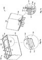
- Fig. 1a
- a perspective view of the switch element according to the first exemplary embodiment from below and a detailed view along the seam between the base plate and the top, at the location of a gap;
- Fig. 1b
- a perspective view of the switch element according to the first exemplary embodiment from above and a cross-section through the seam between the base plate and the top at the location of a gap;
- Fig. 2
- a perspective view of the switch element according to the second exemplary embodiment and a section from a cross-section through the top at the location of the opening/hole;
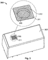
- Fig. 3
- a perspective view of the switch element according to the third exemplary embodiment and a detailed top view of the opening with the grid.
- The exemplary embodiments of the present invention have a base plate and a top. Here the top covers/encloses a surface of the base plate such that a cavity is produced between this surface of the base plate and the top. Contacts for closing or opening an electrical circuit are provided in the cavity. Voltage can be applied to these contacts by means of connecting terminals which are passed through the base plate. Due to this voltage, upon opening or closing the contacts a switching spark or a switching arc may occur. The latter may ignite an explosive mixture located within the switch element and cause it to explode.
-
Figures 1a and 1b show a perspective view of the switch element according to the first exemplary embodiment of the present invention. HereFigure 1a shows a view from below of thebase plate 101 of theswitch element 100, andFigure 1b shows a view from above of the top 102 of theswitch element 100.Reference number 111 identifies the periphery of thebase plate 101. As can easily be seen fromFigure 1a , the seam extends between thebase plate 101 and the top 102 along theperiphery 111. With the exception of two gaps/joints 105 and 105', which are disposed on opposite sides of thebase plate 101, theswitch element 100 is sealed to the outside with a fillingcompound 104. - Furthermore,
Figure 1a shows a detailed view along the seam between thebase plate 101 and the top 102 at the location of thegap 105, andFigure 1b shows a cross-section through the seam between thebase plate 101 and the top 102 at the location of thegap 105. As can be seen from these figures, thegap 105 extends along the seam between thebase plate 101 and the top 102, and is formed by aside face 107 of thebase plate 101 and aside wall 106 of the top 102. Here theside face 107 of thebase plate 101 is fully covered by theside wall 106 of the top 102. The gap 105' is formed similarly to thegap 105. No fillingcompound 104 is provided at the locations of thebase plate 101 where thegaps 105 and 105' are disposed. - According to the present invention the
gap 105 has a width (or breadth) 109 which is smaller than 0.1 mm. Likewise, according to the present invention thegap 105 has aheight 108 which is greater than one millimetre. Similarly, the gap 105' has a width which is smaller than 0.1 mm and a height which is greater than one millimetre. Furthermore, it is essential for the present invention that the sum of the lengths of thegaps 105 and 105' is smaller than one third of the length of theperiphery 111 of the seam between thebase plate 101 and the top 102. - The two
gaps 105 and 105' constitute an opening of theswitch element 100 to the outside via which the explosive energy, which is released during an explosion within theswitch element 100, can escape to the outside, for example in a potentially explosive area. The twogaps 105 and 105' in the first exemplary embodiment of the present invention have dimensions, however, such that they spread the explosive energy escaping into the potentially explosive space over a sufficiently long period of time. The sufficiently long period of time is chosen here such that the explosive energy escaping to the outside is not capable of igniting the explosive mixture of the potentially explosive area or of causing it to explode. In other words, the sufficiently long period of time is such that the explosive energy escaping to the outside does not increase the density of energy in the immediate vicinity of the switch element such that this can trigger an explosion in the potentially explosive area. - In the exemplary embodiment shown in
Figures 1a and 1b theswitch element 100 has an opening with twojoints 105 and 105' and has a substantially rectangular-parallelepipedal form. However, the present invention is not restricted to this exemplary embodiment, but also includes exemplary embodiments in which the switch element has i) just one gap or ii) more than two gaps between the base plate and the top. - In case i) the switch element has an opening which is formed as a gap between the base plate and the top along the seam between the base plate and the top. Here the gap serving as an opening has a length that is smaller than one third of the length of the periphery of the seam between the base plate and the top. The part of the seam between the base plate and the top that is not part of the gap is sealed. Likewise, the seam between the base plate and the connecting terminals is sealed. The width of the gap serving as an opening is smaller than 0.1 mm and its height is greater than one millimetre.
- In case ii) the switch element has an opening which is in the form of a plurality of gaps between the base plate and the top along the seam between the base plate and the top. Here the plurality of gaps have a total length which is smaller than one third of the length of the periphery of the seam between the base plate and the top. The part of the seam between the base plate and the top which does not form part of the plurality of gaps is sealed. Likewise, the seam between the base plate and the connecting terminals is sealed. The width of each gap of the plurality of gaps is smaller than 0.1 mm and its height is greater than one millimetre.
- Furthermore, the exemplary embodiment shown in
Figures 1a and 1b is formed such that the seam between thebase plate 101 and the top 102 extends along theperiphery 111 of thebase plate 101 and theside walls 106 of the top 102 totally cover the side faces 107 of the base plate. However, the present invention is not restricted to this exemplary embodiment, but also includes exemplary embodiments wherein the top, along the seam, only partially covers the side faces of the base plate. In this case, at least at the point where the gap or the gaps are provided, the base plate must have a thickness which is greater than one millimetre. The present invention also includes exemplary embodiments wherein the lower edge of the top is placed on the surface of the base plate with the contacts for closing and opening an electrical circuit. In this case the periphery of the seam between the top and the base plate is substantially predetermined by the periphery of the lower edge of the top. -
Figure 2 shows a perspective view of theswitch element 200 according to the second exemplary embodiment of the present invention. The second exemplary embodiment has in the base plate (this is not shown inFigure 2 ) or in the top 202 an opening orhole 205. InFigure 2 the hole or theopening 205 is provided in the top 302. Otherwise, theswitch element 200 is sealed to the outside. In particular, the seam between the base plate and the top 202 and the seam between the base plate and the connecting terminals (these are not shown inFigure 2 ) is sealed with filling compound. - Furthermore,
Figure 2 shows a section of a cross-section through the cap at the point at which the opening/hole 205 is provided. In the second exemplary embodiment thehole 205 is cylindrical. Thehole 205 has adiameter 209 which is smaller than 0.4 mm and a height/depth 208 that is greater than 1.2 mm. - In the
switch element 200 according to the second exemplary embodiment the explosive energy which is released during an explosion within theswitch element 200 can escape via thehole 205 to the outside, for example into a potentially explosive area. However, thehole 205 has dimensions such that it spreads the explosive energy escaping into the potentially explosive space over a sufficiently long period of time; and it is spread such that the explosive energy escaping to the outside can not cause the explosive mixture of the potentially explosive area to explode. - In the exemplary embodiment shown in
Figure 2 the hole is provided in the middle of the top 202. However, the position of thehole 205 on the top 202 or the base plate is not crucial for the present invention. In fact, thehole 205 can be located at any point on the top 202 or at any point on the base plate. - Furthermore, the present invention is not restricted to a
circular hole 205. In fact, the cross-sectional area of the hole may be of any form, for example oval, rectangular or square. - In these cases it is also essential for the present invention that the cross-sectional area of the hole has a surface area smaller than 0.1256 mm2 and a height or a depth that is greater than 1.2 mm.
- The present invention also includes exemplary embodiments wherein the hole (or the opening) is conical in form in the longitudinal direction. Preferably, in this case the hole tapers inwardly or outwardly. The hole can also have a biconical or meandering form in the longitudinal direction. Preferably, the hole tapers in the middle part or at its ends if the hole has a biconical form.
- It is essential for the present invention that in all cases in which the hole has cross-sectional areas with different surface areas, the cross-sectional area of the hole has at its narrowest point a surface area that is smaller than 0.1256 mm2 and a height or depth that is greater than 1.2 mm.
-
Figure 3 shows a perspective view of theswitch element 300 according to the third exemplary embodiment of the present invention. The third exemplary embodiment has in the base plate (this is not shown inFigure 3 ) or in the top 202 an opening orhole 305 that is covered from the outside with ametal grid 311 and that has a mesh size of less than 0.1 mm. InFigure 3 the hole or theopening 305 is provided in the top 302. Otherwise, theswitch element 300 is sealed to the outside. In particular, the seam between the base plate and the top 302 and the seam between the base plate and the connecting terminals are sealed with filling compound. - Furthermore,
Figure 3 shows a detailed top view of theopening 305 with themetal grid 311. In the third exemplary embodiment themetal grid 311 has rectangular or square meshes which have a surface area smaller than 0.01 mm2. The shape of the opening or of thehole 305, its height or depth, and the surface area of the cross-sectional area at its narrowest point are not essential for the present invention. However, thehole 305 may not be too small. The position of thehole 305 on the base plate or on the top 302 is not essential for the present invention either. - In the
switch element 300 according to the third exemplary embodiment, the explosive energy which is released during an explosion within theswitch element 300 can escape to the outside via thehole 305 covered by thegrid 311, for example into a potentially explosive area. However, thegrid 311, in particular itsmesh size 312, has dimensions such that it first of all spreads the explosive energy escaping into the potentially explosive space over a sufficiently long period of time, and secondly absorbs/stores part of the explosive energy itself. The combination of these two effects ultimately leads to the explosive energy escaping to the outside not being able to cause the explosive mixture of the potentially explosive area to explode. - The
grid 311 used in the third exemplary embodiment need not be made of metal. In fact, the grid can be produced from a plastic that is covered with a metal or contains metal; or else the grid can be a ceramic grid that is covered with metal or contains metal. The form of themesh 312 is not essential for the present invention either. In fact, this mesh can be of any form, for example circular, oval or diamond-shaped. In all of these cases it is essential for the invention that the surface area of themesh 312 is smaller than 0.01 mm2. - Switch elements according to the present invention are preferably relays. Relays according to the first, second and third exemplary embodiment of the present invention have been tested in special laboratories according to standard IEC 60079-15, paragraph 22.4.3. The tests showed that these relays correspond to standard IEC 60079-15, paragraph 22.4.3, and are therefore suitable for use as switch elements in a potentially explosive area.
- Switch elements according to the present invention are used, for example, for connecting mains voltages (230 V for single-phase or 400 V for three-phase alternating voltages) in potentially explosive areas in order to prevent ignition of the mixture present in the potentially explosive area due to a switching spark/switching arc occurring within the switch element.
List of reference numbers: Reference number Description 100 Switch element according to the first exemplary embodiment 101 Base plate 102 Top 103 Filling compound for sealing 104 Connecting terminal 105, 105' Gap between the base plate and the top 106 Side wall of the top 107 Side face of the base plate 108 Height of the gap 109 Width/Breadth of the gap 110 Length of the gap along the peripheral direction of the base plate 111 Periphery of the base plate 200 Switch element according to the second exemplary embodiment 202 Top 205 Opening/ Hole 208 Depth/Height of the opening 209 Diameter of the opening 300 Switch element according to the third exemplary embodiment 302 Top 305 Opening/ Hole 311 Close meshed grid 312 Mesh of the grid
Claims (9)
- A switch element for use in a potentially explosive area that has a base plate and a top, the top covering/enclosing a surface of the base plate such that there is produced between a surface of the base plate and the top a cavity in which there are contacts for closing and opening an electrical circuit, and
the switch element also having an opening to the outside and otherwise being sealed to the outside,
characterized in that:the opening (205) is provided either in the base plate or in the top (202); the cross-sectional area of the opening (205) has at its narrowest point a surface area that is smaller than 0.1256 mm2; andat the point at which the opening (205) is provided, the base plate or the top (202) has a thickness which is greater than 1.2 mm so that the depth (208) of the opening (205) is greater than 1.2 mm;wherein a cross-sectional area of the opening (205) is round, in particular oval or circularorwherein a cross-sectional area of the opening is angular, in particular square or rectangular; andwherein the opening (205) is in the form of a cone which tapers either inwardly or outwardly, or the opening has a biconical form which is tapered in the middle part or at the ends. - A switch element for use in a potentially explosive area that has a base plate and a top, the top covering/enclosing a surface of the base plate such that there is produced between a surface of the base plate and the top a cavity in which there are contacts for closing and opening an electrical circuit, and
the switch element also having an opening to the outside and otherwise being sealed to the outside,
characterized in that:the opening (305) is provided either in the base plate or in the top (302) and is covered from the outside with a grid (311) the mesh (312) of which has a surface area which is smaller than 0.01 mm2; andwherein the grid (311) is produced from a metal or the grid (311) is produced from a plastic that is covered with a metal or contains metal, or the grid (311) is a ceramic grid that is covered with a metal or contains metal. - The switch element according to Claim 2, characterised in that the mesh (312) of the grid (311) is square and has a mesh size which is smaller than 0.1 mm.
- A switch element for use in a potentially explosive area that has a base plate and a top, the top covering/enclosing a surface of the base plate such that there is produced between a surface of the base plate and the top a cavity in which there are contacts for closing and opening an electrical circuit, and
the switch element also having an opening to the outside and otherwise being sealed to the outside,
wherein the opening is made as a gap (105) between the base plate and the top along the seam between the base plate (101) and the top (102),
the gap (105) serving as an opening has a length (110) that is smaller than one third of the length of the periphery of the seam between the base plate (101) and the top (102), the part of the seam between the base plate (101) and the top (102) that is not part of the gap (105) is sealed,
characterized in that:the width (109) of the gap (105) serving as an opening is smaller than 0.1 mm,the height (108) of the gap (105) is greater than one millimetre;wherein the seam between the base plate (101) and the top (102) extends along the periphery (111) of the base plate (101) and along the seam; the top (102) at least partially covers the side faces (107) of the base plate (101); andthe base plate (101) and the top (102) are substantially in the form of a rectangular parallelepiped, and the four side walls (106) of the top (102) totally cover the four side faces (107) of the base plate (101). - A switch element for use in a potentially explosive area that has a base plate and a top, the top covering/enclosing a surface of the base plate such that there is produced between a surface of the base plate and the top a cavity in which there are contacts for closing and opening an electrical circuit, and
the switch element also having an opening to the outside and otherwise being sealed to the outside,
the opening is made as a plurality of gaps (105, 105') between the base plate and the top along the seam between the base plate (101) and the top (102),
the sum of the plurality of gaps (105, 105') serving as the opening have a length which is smaller than one third of the length of the periphery of the seam between the base plate (101) and the top (102),
the part of the seam between the base plate (101) and the top (102) which do not form part of the plurality of gaps (105, 105') is sealed,
characterized in that:the width (109) of each gap of the plurality of gaps (105, 105') is smaller than 0.1 mm,the height (108) of each gap of the plurality of gaps (105, 105') is greater than one millimetre; andwherein the seam between the base plate (101) and the top (102) extends along the periphery (111) of the base plate (101) and along the seam; the top (102) at least partially covers the side faces (107) of the base plate (101); andthe base plate (101) and the top (102) are substantially in the form of a rectangular parallelepiped, and the four side walls (106) of the top (102) totally cover the four side faces (107) of the base plate (101). - The switch element according to any of Claims 1 to 5, characterised in that the switch element is a relay.
- The use of a switch element (200) in a potentially explosive area in order to connect an electrical circuit and thereby prevent ignition of the explosive mixture present in the potentially explosive area due to a switching arc occurring within the switch element,
the switch element (200) having a base plate and a top (202), the top (202) covering/enclosing a surface of the base plate such that there is produced between a surface of the base plate and the top (202) a cavity in which are located contacts for closing or opening an electrical circuit,
the switch element (200) being sealed apart from an opening (205),
the opening (205) being provided either in the base plate or in the top (202),
the cross-sectional area of the opening (205) having a surface area of less than 0.1256 mm2 at its narrowest point,
characterized in that:at the point at which the opening (205) is provided, the base plate and the top (202) having a thickness which is greater than 1.2 mm so that the depth (208) of the opening is greater than 1.2 mm,wherein a cross-sectional area of the opening (205) is round, in particular oval or circular,orwherein a cross-sectional area of the opening is angular, in particular square or rectangular; andthe opening (205) is in form of a cone which tapers either inwardly or outwardly, or the opening has a biconical form which is tapered in the middle part or at the ends. - The use of a switch element (300) in a potentially explosive area in order to connect an electrical circuit and thereby prevent ignition of the explosive mixture present in the potentially explosive area due to a switching arc occurring within the switch element,
the switch element (300) having a base plate and a top (302), the top (302) covering/enclosing a surface of the base plate such that there is produced between a surface of the base plate and the top (302) a cavity in which there are contacts for closing and opening an electrical circuit,
the switch element (300) being sealed apart from an opening (305),
characterized in that:the opening (305) being provided either in the base plate or in the top (302) and being covered from the outside with a grid (311) the mesh (312) of which has a surface area smaller than 0,01 mm2, andwherein the grid (311) is produced from a metal or the grid (311) is produced from a plastic that is covered with a metal or contains metal, or the grid (311) is a ceramic grid that is covered with a metal or contains metal. - The use of a switch element (100) in a potentially explosive area in order to connect an electrical circuit and thereby prevent ignition of the explosive mixture present in the potentially explosive area due to a switching arc occurring within the switch element,
the switch element (100) having a base plate (101) and a top (102), the top (102) covering/enclosing a surface of the base plate (101) such that there is produced between a surface of the base plate (101) and the top (102) a cavity in which there are contacts for closing and opening an electrical circuit,
a gap (105) or a plurality of gaps (105, 105') being formed between the base plate and the top along the seam between the base plate (101) and the top (102),
the gap (105) having a length (110) and the plurality of gaps (105, 105') having a total length (110) which is smaller than one third of the length of the periphery of the seam between the base plate (101) and the top (102),
the part of the seam between the base plate (101) and the top (102) not forming part of the gap (105) or the plurality of gaps (105, 105') being sealed,
the switch element (100) also otherwise being sealed,
characterized in that:the width (107) of the gap (105) or the width of each gap of the plurality of gaps (105, 105') being smaller than 0.1 mm, andthe height (108) of the gap (105) or the height of each gap of the plurality (105, 105') of gaps being greater than one millimetre; andwherein the seam between the base plate (101) and the top (102) extends along the periphery (111) of the base plate (101) and along the seam; the top (102) at least partially covers the side faces (107) of the base plate (101); andthe base plate (101) and the top (102) are substantially in the form of a rectangular parallelepiped, and the four side walls (106) of the top (102) totally cover the four side faces (107) of the base plate (101).
Applications Claiming Priority (2)
| Application Number | Priority Date | Filing Date | Title |
|---|---|---|---|
| DE102014006957.5A DE102014006957A1 (en) | 2014-05-12 | 2014-05-12 | Switching element for use in a potentially explosive area |
| PCT/EP2015/059688 WO2015173046A1 (en) | 2014-05-12 | 2015-05-04 | Switch element for use in a potentially explosive area |
Publications (2)
| Publication Number | Publication Date |
|---|---|
| EP3143632A1 EP3143632A1 (en) | 2017-03-22 |
| EP3143632B1 true EP3143632B1 (en) | 2020-07-01 |
Family
ID=53059093
Family Applications (1)
| Application Number | Title | Priority Date | Filing Date |
|---|---|---|---|
| EP15721202.8A Active EP3143632B1 (en) | 2014-05-12 | 2015-05-04 | Switch element for use in a potentially explosive area |
Country Status (6)
| Country | Link |
|---|---|
| US (1) | US10283286B2 (en) |
| EP (1) | EP3143632B1 (en) |
| JP (1) | JP2017516266A (en) |
| CN (2) | CN112185728A (en) |
| DE (1) | DE102014006957A1 (en) |
| WO (1) | WO2015173046A1 (en) |
Families Citing this family (2)
| Publication number | Priority date | Publication date | Assignee | Title |
|---|---|---|---|---|
| JP7326739B2 (en) * | 2018-12-27 | 2023-08-16 | オムロン株式会社 | electronic components |
| US20210247096A1 (en) * | 2020-02-07 | 2021-08-12 | Carrier Corporation | A2l compliant contactor |
Citations (1)
| Publication number | Priority date | Publication date | Assignee | Title |
|---|---|---|---|---|
| GB1450724A (en) * | 1972-04-28 | 1976-09-29 | Airpax Electronics | Electrical circuit breaker |
Family Cites Families (22)
| Publication number | Priority date | Publication date | Assignee | Title |
|---|---|---|---|---|
| BE526254A (en) * | 1953-02-06 | |||
| JPS4712428Y1 (en) * | 1968-12-26 | 1972-05-09 | ||
| US4177367A (en) * | 1978-07-18 | 1979-12-04 | Amf Incorporated | Push button switch |
| US4260863A (en) * | 1978-11-06 | 1981-04-07 | Appleton Arthur I | Vented plastic enclosure for arcing devices |
| DE2902169C2 (en) * | 1979-01-20 | 1983-07-21 | AEG-Telefunken Nachrichtentechnik GmbH, 7150 Backnang | Rainproof and splash-proof housing to accommodate electrical devices |
| JPS5619814A (en) * | 1979-07-27 | 1981-02-24 | Mitsubishi Electric Corp | Switching device |
| US4620863A (en) * | 1981-07-02 | 1986-11-04 | Rensselaer Polytechnic Institute | Radiation coloration resistant glass |
| JPS5866537U (en) * | 1981-10-29 | 1983-05-06 | オリジナル電機株式会社 | relay |
| US4427863A (en) * | 1982-03-22 | 1984-01-24 | Izumi Denki Corporation | Small-sized relay and method for fabricating the same |
| JP3004854U (en) * | 1994-05-23 | 1994-11-29 | 光樹 永本 | Cover structure of electromagnetic relay |
| DE19634673C2 (en) * | 1996-08-28 | 1998-08-27 | Stahl R Schaltgeraete Gmbh | Plastic housing in the "flameproof enclosure" type of protection |
| DE19708116C2 (en) * | 1997-02-28 | 1999-02-25 | Telefunken Microelectron | Arrangement for closing pressure equalization openings |
| JPH11125482A (en) | 1997-10-21 | 1999-05-11 | Matsushita Electric Ind Co Ltd | Ant-explosion unit for refrigerating machine employing inflammable coolant |
| DE19840761C1 (en) * | 1998-09-07 | 2000-05-04 | Daimler Chrysler Ag | Method of manufacturing a moisture-proof pressure compensation element for a housing |
| DE202006001911U1 (en) * | 2005-03-02 | 2006-06-22 | Crastal Technology (Shenzhen) Co., Ltd. | Relay switch for toaster |
| JP4712428B2 (en) | 2005-04-25 | 2011-06-29 | 日本高圧電気株式会社 | Device for measuring objects |
| US7321281B2 (en) * | 2005-05-17 | 2008-01-22 | Gigavac Llc | Hermetically sealed relay having low permeability plastic housing |
| JP4540064B2 (en) * | 2005-09-09 | 2010-09-08 | Necトーキン株式会社 | Electromagnetic relay |
| DE102007024421C5 (en) | 2007-05-25 | 2016-05-19 | Cooper Crouse-Hinds Gmbh | Housing for an electrical equipment |
| JP5131218B2 (en) * | 2008-09-12 | 2013-01-30 | アンデン株式会社 | Electromagnetic relay |
| JP5131219B2 (en) * | 2009-02-02 | 2013-01-30 | アンデン株式会社 | Electromagnetic relay |
| JP5018845B2 (en) | 2009-08-20 | 2012-09-05 | 富士電機機器制御株式会社 | Magnetic contactor |
-
2014
- 2014-05-12 DE DE102014006957.5A patent/DE102014006957A1/en not_active Withdrawn
-
2015
- 2015-05-04 EP EP15721202.8A patent/EP3143632B1/en active Active
- 2015-05-04 WO PCT/EP2015/059688 patent/WO2015173046A1/en active Application Filing
- 2015-05-04 CN CN202010908848.XA patent/CN112185728A/en active Pending
- 2015-05-04 JP JP2016567420A patent/JP2017516266A/en active Pending
- 2015-05-04 CN CN201580025236.3A patent/CN106463288A/en active Pending
-
2016
- 2016-11-10 US US15/348,418 patent/US10283286B2/en active Active
Patent Citations (1)
| Publication number | Priority date | Publication date | Assignee | Title |
|---|---|---|---|---|
| GB1450724A (en) * | 1972-04-28 | 1976-09-29 | Airpax Electronics | Electrical circuit breaker |
Also Published As
| Publication number | Publication date |
|---|---|
| EP3143632A1 (en) | 2017-03-22 |
| US10283286B2 (en) | 2019-05-07 |
| CN106463288A (en) | 2017-02-22 |
| WO2015173046A1 (en) | 2015-11-19 |
| CN112185728A (en) | 2021-01-05 |
| DE102014006957A1 (en) | 2015-11-12 |
| US20170062147A1 (en) | 2017-03-02 |
| JP2017516266A (en) | 2017-06-15 |
Similar Documents
| Publication | Publication Date | Title |
|---|---|---|
| RU2710540C1 (en) | Disconnection device for overvoltage limiter and protective device containing overvoltage limiter connected to such disconnecting device | |
| RU2497250C1 (en) | Overvoltage protection device | |
| US11682899B2 (en) | Protection of a surge arrester with a better protection against failure from thermal overload in case of a temporary overvoltage in an electrical grid line | |
| JPH0145173B2 (en) | ||
| EP3143632B1 (en) | Switch element for use in a potentially explosive area | |
| US10332697B2 (en) | Encapsulation of components and a low energy circuit for hazardous locations | |
| US3291937A (en) | Explosive disconnect having the explosive means thermally and electrically isolated from resistance ignition means | |
| US2422978A (en) | Lightning arrester | |
| CA1144962A (en) | Piston actuated striker for electric fuse | |
| US3560794A (en) | Lightning arrester with a rupturable diaphragm for gas pressure release | |
| CN105552720B (en) | Surge voltage protector | |
| CN203895381U (en) | Fireproof separator plate and plug-type breaker comprising the same | |
| EP3373401B1 (en) | Disconnector arrangement and fabrication method | |
| JP2005521225A (en) | Arc resistant enclosure of switchgear | |
| JP6562269B2 (en) | Surge protective element | |
| JPH0356030Y2 (en) | ||
| JP6170466B2 (en) | Surge protector | |
| CN107078467B (en) | Arrangement for disconnecting a surge arrester network in the presence of transient overvoltages | |
| JPS5963684A (en) | Arrester | |
| JPS63294639A (en) | Cutout | |
| JPS63294638A (en) | Cutout | |
| PL226463B1 (en) | Vacuum chamber for the high voltage circuit-breaker |
Legal Events
| Date | Code | Title | Description |
|---|---|---|---|
| STAA | Information on the status of an ep patent application or granted ep patent |
Free format text: STATUS: THE INTERNATIONAL PUBLICATION HAS BEEN MADE |
|
| PUAI | Public reference made under article 153(3) epc to a published international application that has entered the european phase |
Free format text: ORIGINAL CODE: 0009012 |
|
| STAA | Information on the status of an ep patent application or granted ep patent |
Free format text: STATUS: REQUEST FOR EXAMINATION WAS MADE |
|
| 17P | Request for examination filed |
Effective date: 20161207 |
|
| AK | Designated contracting states |
Kind code of ref document: A1 Designated state(s): AL AT BE BG CH CY CZ DE DK EE ES FI FR GB GR HR HU IE IS IT LI LT LU LV MC MK MT NL NO PL PT RO RS SE SI SK SM TR |
|
| AX | Request for extension of the european patent |
Extension state: BA ME |
|
| DAV | Request for validation of the european patent (deleted) | ||
| DAX | Request for extension of the european patent (deleted) | ||
| STAA | Information on the status of an ep patent application or granted ep patent |
Free format text: STATUS: EXAMINATION IS IN PROGRESS |
|
| 17Q | First examination report despatched |
Effective date: 20190321 |
|
| GRAP | Despatch of communication of intention to grant a patent |
Free format text: ORIGINAL CODE: EPIDOSNIGR1 |
|
| STAA | Information on the status of an ep patent application or granted ep patent |
Free format text: STATUS: GRANT OF PATENT IS INTENDED |
|
| INTG | Intention to grant announced |
Effective date: 20200212 |
|
| RIN1 | Information on inventor provided before grant (corrected) |
Inventor name: KROEPFL, CHRISTIAN |
|
| GRAS | Grant fee paid |
Free format text: ORIGINAL CODE: EPIDOSNIGR3 |
|
| GRAA | (expected) grant |
Free format text: ORIGINAL CODE: 0009210 |
|
| STAA | Information on the status of an ep patent application or granted ep patent |
Free format text: STATUS: THE PATENT HAS BEEN GRANTED |
|
| AK | Designated contracting states |
Kind code of ref document: B1 Designated state(s): AL AT BE BG CH CY CZ DE DK EE ES FI FR GB GR HR HU IE IS IT LI LT LU LV MC MK MT NL NO PL PT RO RS SE SI SK SM TR |
|
| REG | Reference to a national code |
Ref country code: CH Ref legal event code: EP Ref country code: AT Ref legal event code: REF Ref document number: 1286934 Country of ref document: AT Kind code of ref document: T Effective date: 20200715 |
|
| REG | Reference to a national code |
Ref country code: IE Ref legal event code: FG4D |
|
| REG | Reference to a national code |
Ref country code: DE Ref legal event code: R096 Ref document number: 602015055053 Country of ref document: DE |
|
| REG | Reference to a national code |
Ref country code: LT Ref legal event code: MG4D |
|
| PG25 | Lapsed in a contracting state [announced via postgrant information from national office to epo] |
Ref country code: BG Free format text: LAPSE BECAUSE OF FAILURE TO SUBMIT A TRANSLATION OF THE DESCRIPTION OR TO PAY THE FEE WITHIN THE PRESCRIBED TIME-LIMIT Effective date: 20201001 |
|
| REG | Reference to a national code |
Ref country code: NL Ref legal event code: MP Effective date: 20200701 |
|
| REG | Reference to a national code |
Ref country code: AT Ref legal event code: MK05 Ref document number: 1286934 Country of ref document: AT Kind code of ref document: T Effective date: 20200701 |
|
| PG25 | Lapsed in a contracting state [announced via postgrant information from national office to epo] |
Ref country code: NO Free format text: LAPSE BECAUSE OF FAILURE TO SUBMIT A TRANSLATION OF THE DESCRIPTION OR TO PAY THE FEE WITHIN THE PRESCRIBED TIME-LIMIT Effective date: 20201001 Ref country code: SE Free format text: LAPSE BECAUSE OF FAILURE TO SUBMIT A TRANSLATION OF THE DESCRIPTION OR TO PAY THE FEE WITHIN THE PRESCRIBED TIME-LIMIT Effective date: 20200701 Ref country code: GR Free format text: LAPSE BECAUSE OF FAILURE TO SUBMIT A TRANSLATION OF THE DESCRIPTION OR TO PAY THE FEE WITHIN THE PRESCRIBED TIME-LIMIT Effective date: 20201002 Ref country code: ES Free format text: LAPSE BECAUSE OF FAILURE TO SUBMIT A TRANSLATION OF THE DESCRIPTION OR TO PAY THE FEE WITHIN THE PRESCRIBED TIME-LIMIT Effective date: 20200701 Ref country code: PT Free format text: LAPSE BECAUSE OF FAILURE TO SUBMIT A TRANSLATION OF THE DESCRIPTION OR TO PAY THE FEE WITHIN THE PRESCRIBED TIME-LIMIT Effective date: 20201102 Ref country code: AT Free format text: LAPSE BECAUSE OF FAILURE TO SUBMIT A TRANSLATION OF THE DESCRIPTION OR TO PAY THE FEE WITHIN THE PRESCRIBED TIME-LIMIT Effective date: 20200701 Ref country code: FI Free format text: LAPSE BECAUSE OF FAILURE TO SUBMIT A TRANSLATION OF THE DESCRIPTION OR TO PAY THE FEE WITHIN THE PRESCRIBED TIME-LIMIT Effective date: 20200701 Ref country code: CZ Free format text: LAPSE BECAUSE OF FAILURE TO SUBMIT A TRANSLATION OF THE DESCRIPTION OR TO PAY THE FEE WITHIN THE PRESCRIBED TIME-LIMIT Effective date: 20200701 Ref country code: LT Free format text: LAPSE BECAUSE OF FAILURE TO SUBMIT A TRANSLATION OF THE DESCRIPTION OR TO PAY THE FEE WITHIN THE PRESCRIBED TIME-LIMIT Effective date: 20200701 Ref country code: HR Free format text: LAPSE BECAUSE OF FAILURE TO SUBMIT A TRANSLATION OF THE DESCRIPTION OR TO PAY THE FEE WITHIN THE PRESCRIBED TIME-LIMIT Effective date: 20200701 |
|
| PG25 | Lapsed in a contracting state [announced via postgrant information from national office to epo] |
Ref country code: PL Free format text: LAPSE BECAUSE OF FAILURE TO SUBMIT A TRANSLATION OF THE DESCRIPTION OR TO PAY THE FEE WITHIN THE PRESCRIBED TIME-LIMIT Effective date: 20200701 Ref country code: LV Free format text: LAPSE BECAUSE OF FAILURE TO SUBMIT A TRANSLATION OF THE DESCRIPTION OR TO PAY THE FEE WITHIN THE PRESCRIBED TIME-LIMIT Effective date: 20200701 Ref country code: RS Free format text: LAPSE BECAUSE OF FAILURE TO SUBMIT A TRANSLATION OF THE DESCRIPTION OR TO PAY THE FEE WITHIN THE PRESCRIBED TIME-LIMIT Effective date: 20200701 Ref country code: IS Free format text: LAPSE BECAUSE OF FAILURE TO SUBMIT A TRANSLATION OF THE DESCRIPTION OR TO PAY THE FEE WITHIN THE PRESCRIBED TIME-LIMIT Effective date: 20201101 |
|
| PG25 | Lapsed in a contracting state [announced via postgrant information from national office to epo] |
Ref country code: NL Free format text: LAPSE BECAUSE OF FAILURE TO SUBMIT A TRANSLATION OF THE DESCRIPTION OR TO PAY THE FEE WITHIN THE PRESCRIBED TIME-LIMIT Effective date: 20200701 |
|
| REG | Reference to a national code |
Ref country code: DE Ref legal event code: R097 Ref document number: 602015055053 Country of ref document: DE |
|
| PG25 | Lapsed in a contracting state [announced via postgrant information from national office to epo] |
Ref country code: IT Free format text: LAPSE BECAUSE OF FAILURE TO SUBMIT A TRANSLATION OF THE DESCRIPTION OR TO PAY THE FEE WITHIN THE PRESCRIBED TIME-LIMIT Effective date: 20200701 Ref country code: DK Free format text: LAPSE BECAUSE OF FAILURE TO SUBMIT A TRANSLATION OF THE DESCRIPTION OR TO PAY THE FEE WITHIN THE PRESCRIBED TIME-LIMIT Effective date: 20200701 Ref country code: RO Free format text: LAPSE BECAUSE OF FAILURE TO SUBMIT A TRANSLATION OF THE DESCRIPTION OR TO PAY THE FEE WITHIN THE PRESCRIBED TIME-LIMIT Effective date: 20200701 Ref country code: SM Free format text: LAPSE BECAUSE OF FAILURE TO SUBMIT A TRANSLATION OF THE DESCRIPTION OR TO PAY THE FEE WITHIN THE PRESCRIBED TIME-LIMIT Effective date: 20200701 Ref country code: EE Free format text: LAPSE BECAUSE OF FAILURE TO SUBMIT A TRANSLATION OF THE DESCRIPTION OR TO PAY THE FEE WITHIN THE PRESCRIBED TIME-LIMIT Effective date: 20200701 |
|
| PLBE | No opposition filed within time limit |
Free format text: ORIGINAL CODE: 0009261 |
|
| STAA | Information on the status of an ep patent application or granted ep patent |
Free format text: STATUS: NO OPPOSITION FILED WITHIN TIME LIMIT |
|
| PG25 | Lapsed in a contracting state [announced via postgrant information from national office to epo] |
Ref country code: AL Free format text: LAPSE BECAUSE OF FAILURE TO SUBMIT A TRANSLATION OF THE DESCRIPTION OR TO PAY THE FEE WITHIN THE PRESCRIBED TIME-LIMIT Effective date: 20200701 |
|
| 26N | No opposition filed |
Effective date: 20210406 |
|
| PG25 | Lapsed in a contracting state [announced via postgrant information from national office to epo] |
Ref country code: SK Free format text: LAPSE BECAUSE OF FAILURE TO SUBMIT A TRANSLATION OF THE DESCRIPTION OR TO PAY THE FEE WITHIN THE PRESCRIBED TIME-LIMIT Effective date: 20200701 |
|
| PG25 | Lapsed in a contracting state [announced via postgrant information from national office to epo] |
Ref country code: SI Free format text: LAPSE BECAUSE OF FAILURE TO SUBMIT A TRANSLATION OF THE DESCRIPTION OR TO PAY THE FEE WITHIN THE PRESCRIBED TIME-LIMIT Effective date: 20200701 |
|
| REG | Reference to a national code |
Ref country code: DE Ref legal event code: R119 Ref document number: 602015055053 Country of ref document: DE |
|
| REG | Reference to a national code |
Ref country code: CH Ref legal event code: PL |
|
| GBPC | Gb: european patent ceased through non-payment of renewal fee |
Effective date: 20210504 |
|
| PG25 | Lapsed in a contracting state [announced via postgrant information from national office to epo] |
Ref country code: MC Free format text: LAPSE BECAUSE OF FAILURE TO SUBMIT A TRANSLATION OF THE DESCRIPTION OR TO PAY THE FEE WITHIN THE PRESCRIBED TIME-LIMIT Effective date: 20200701 Ref country code: LU Free format text: LAPSE BECAUSE OF NON-PAYMENT OF DUE FEES Effective date: 20210504 Ref country code: LI Free format text: LAPSE BECAUSE OF NON-PAYMENT OF DUE FEES Effective date: 20210531 Ref country code: CH Free format text: LAPSE BECAUSE OF NON-PAYMENT OF DUE FEES Effective date: 20210531 |
|
| REG | Reference to a national code |
Ref country code: BE Ref legal event code: MM Effective date: 20210531 |
|
| PG25 | Lapsed in a contracting state [announced via postgrant information from national office to epo] |
Ref country code: IE Free format text: LAPSE BECAUSE OF NON-PAYMENT OF DUE FEES Effective date: 20210504 Ref country code: GB Free format text: LAPSE BECAUSE OF NON-PAYMENT OF DUE FEES Effective date: 20210504 Ref country code: DE Free format text: LAPSE BECAUSE OF NON-PAYMENT OF DUE FEES Effective date: 20211201 |
|
| PG25 | Lapsed in a contracting state [announced via postgrant information from national office to epo] |
Ref country code: FR Free format text: LAPSE BECAUSE OF NON-PAYMENT OF DUE FEES Effective date: 20210531 |
|
| PG25 | Lapsed in a contracting state [announced via postgrant information from national office to epo] |
Ref country code: BE Free format text: LAPSE BECAUSE OF NON-PAYMENT OF DUE FEES Effective date: 20210531 |
|
| PG25 | Lapsed in a contracting state [announced via postgrant information from national office to epo] |
Ref country code: HU Free format text: LAPSE BECAUSE OF FAILURE TO SUBMIT A TRANSLATION OF THE DESCRIPTION OR TO PAY THE FEE WITHIN THE PRESCRIBED TIME-LIMIT; INVALID AB INITIO Effective date: 20150504 |
|
| PG25 | Lapsed in a contracting state [announced via postgrant information from national office to epo] |
Ref country code: CY Free format text: LAPSE BECAUSE OF FAILURE TO SUBMIT A TRANSLATION OF THE DESCRIPTION OR TO PAY THE FEE WITHIN THE PRESCRIBED TIME-LIMIT Effective date: 20200701 |
|
| PG25 | Lapsed in a contracting state [announced via postgrant information from national office to epo] |
Ref country code: MK Free format text: LAPSE BECAUSE OF FAILURE TO SUBMIT A TRANSLATION OF THE DESCRIPTION OR TO PAY THE FEE WITHIN THE PRESCRIBED TIME-LIMIT Effective date: 20200701 |