EP3143419B1 - Superconducting component and associated amplifier - Google Patents
Superconducting component and associated amplifier Download PDFInfo
- Publication number
- EP3143419B1 EP3143419B1 EP15723017.8A EP15723017A EP3143419B1 EP 3143419 B1 EP3143419 B1 EP 3143419B1 EP 15723017 A EP15723017 A EP 15723017A EP 3143419 B1 EP3143419 B1 EP 3143419B1
- Authority
- EP
- European Patent Office
- Prior art keywords
- josephson junction
- quantum interference
- current
- superconducting quantum
- superconducting
- Prior art date
- Legal status (The legal status is an assumption and is not a legal conclusion. Google has not performed a legal analysis and makes no representation as to the accuracy of the status listed.)
- Active
Links
Images


Classifications
-
- G—PHYSICS
- G01—MEASURING; TESTING
- G01R—MEASURING ELECTRIC VARIABLES; MEASURING MAGNETIC VARIABLES
- G01R33/00—Arrangements or instruments for measuring magnetic variables
- G01R33/02—Measuring direction or magnitude of magnetic fields or magnetic flux
- G01R33/035—Measuring direction or magnitude of magnetic fields or magnetic flux using superconductive devices
-
- G—PHYSICS
- G01—MEASURING; TESTING
- G01R—MEASURING ELECTRIC VARIABLES; MEASURING MAGNETIC VARIABLES
- G01R31/00—Arrangements for testing electric properties; Arrangements for locating electric faults; Arrangements for electrical testing characterised by what is being tested not provided for elsewhere
- G01R31/28—Testing of electronic circuits, e.g. by signal tracer
- G01R31/302—Contactless testing
- G01R31/312—Contactless testing by capacitive methods
-
- H—ELECTRICITY
- H03—ELECTRONIC CIRCUITRY
- H03F—AMPLIFIERS
- H03F19/00—Amplifiers using superconductivity effects
Definitions
- the present invention relates to a superconducting component.
- the invention also relates to an amplifier comprising such a component.
- Superconducting components are used in multiple applications including determination of magnetic susceptibilities of tiny samples over a wide temperature range, detection of magnetic and quadrupole nuclear resonance, measurement of temperature using noise measurements also called noise thermometry, biomagnetism, geophysics, rock magnetism or paleomagnetism.
- the Josephson effect is used.
- the Josephson effect is manifested by the appearance of a current, also called supracurrant, between two superconducting materials separated by a non-superconducting layer, e.g. formed of a non-superconducting insulating or metallic material.
- the set of both superconducting materials and the layer is called a "Josephson junction".
- a SQUID is a superconducting loop (closed track formed of at least one superconducting material, electrically equivalent to an inductance of value L) interrupted by at least one insulating layer, each interruption forming a Josephson junction.
- the inductance quantities L of the superconducting loop and the critical currents I C of the Josephson junctions are linked by the ratio R1 between the product L.Ic and the quantum of flux ⁇ 0 .
- the aforementioned arrangement does not allow to precisely control the critical current of the Josephson junction or junctions used in the component.
- the invention proposes a superconducting component comprising a first superconducting loop, the first superconducting loop comprising a first branch comprising a first Josephson junction and a second branch, the second branch comprises a first superconducting device with direct-current quantum interference, the first superconducting DC quantum interference device having a second Josephson junction and a third Josephson junction, a critical current being defined for each Josephson junction, the critical current of the first Josephson junction is greater than the absolute value of the difference between the critical current of the third Josephson junction and the critical current of the second Josephson junction and less than the sum of the critical current of the second Josephson junction and the critical current of the third Josephson junction, the component comprising yens magnetic flux generation in the form of conductive tracks positioned in relation to the branches, a track being coupled to the first superconducting device with quantum interference, the magnetic flux generation means being arranged to efficiently inject a magnetic flux into the first loop superconducting device and the first superconducting DC quantum interference device.
- the magnetic flux generation means are thus a means of controlling the loop current so as to adjust the critical current of the first direct current quantum interference superconducting device.
- the invention also relates to an amplifier comprising an input, two outputs, the potential difference between the two outputs corresponding to an amplification of a signal imposed at the input of the amplifier, two first superconducting elements with quantum interference , said first doublet, mounted in differential and each connected to a respective one of the outputs of the amplifier, the two superconducting elements with quantum interference of the first doublet being selected from a component as previously described and a superconducting device with DC quantum interference or two components as previously described, and a magnetic flux difference control means applied to the two quantum interference superconducting elements of the first doublet.
- a superconducting component is illustrated on the figure 1 .
- the component 10 comprises a first superconducting loop 12, a first coupling means 14 to an external magnetic flux, a second coupling means 16 to an external magnetic flux, a first branch 20, a second branch 22, electrical access 24 and 26 in the form of an input 24 and an output 26 (generally the position of the input 24 and the output 26 are relative to the direction of the electric current), the two branches 20, 22 being each connected to one end at the input 24 and at the other end at Exit 26.
- the first branch 20 comprises a first part 28 formed in a first superconducting material S1, a second part 30 formed in a second superconducting material S2 and a first Josephson junction 32 interposed between the two parts 28 and 30.
- the first part 28 of the first part branch 20 extends between the inlet 24 and the first Josephson junction 32 while the second portion 30 of the first branch 20 extends between the first Josephson junction 32 and the outlet 26.
- the first superconducting material S1 of the first portion 28 of the first branch 20 is preferably a high critical temperature superconductor (> 26 K), of the type of those known by the abbreviation YBaCuO.
- YBaCuO high critical temperature superconductor
- the superconductor is non-metallic, and in particular of the ceramic type based on copper oxide (ReBaCuO, where Re represents a chemical element of the rare earth type).
- the two superconductive materials S1 and S2 are identical, which makes it easier to manufacture the component 10.
- the second branch 22 is different from the first branch 20.
- the second branch 22 comprises a first portion 34 formed in the first superconducting material S1, a second portion 36 formed in the second S2 superconducting material and a quantum interference superconducting device 38 noted SQUID 38 throughout the rest of this description.
- the SQUID 38 is interposed between the two parts 34 and 36 of the second branch 22.
- the first portion 34 of the second branch 22 extends between the inlet 24 and the SQUID 38 while the second portion 36 of the second branch 22 extends between the SQUID 38 and the output 26.
- the branch of the SQUID 38 is electrically arranged in parallel with the branch containing the first Josephson junction 32.
- the SQUID 38 comprises a second superconducting loop 40 having a first line 42 and a second line 44.
- the first line 42 comprises a first portion 46 formed in the first superconducting material S1, a second portion 48 formed in the second superconducting material S2 and a second Josephson junction 50 interposed between the two parts 46, 48 of the first line 42.
- portion 46 of the first line 42 extends between the first portion 34 of the second leg 22 and the second Josephson junction 50 while the second portion 48 of the first line 42 extends between the second Josephson junction 50 and the second portion 36 of the second branch 22.
- the second line 44 comprises a first part 52 made in the first superconducting material S1, a second part 54 made in the second superconducting material S2 and a third Josephson junction 56 interposed between the two parts 52, 54 of the second line 44 so that the third Josephson junction 56 is in parallel with the second Josephson junction 50.
- the first portion 52 of the second line 44 extends between the first portion 34 of the second branch 22 and the third Josephson junction 56 while the second portion 54 of the second the second line 44 extends between the third Josephson junction 56 and the second portion 36 of the second branch 22.
- the SQUID 38 serves mainly as a single Josephson junction whose critical current is adjustable by an "electrical" means (injection of flux in the second superconducting loop 40).
- the first coupling means 14 is in the form of a first track 58.
- the first track 58 is a conductive track connected to a first current generator 60 shown in FIG. figure 2 .
- the first track 58 is opposite the first branch 20, positioned to effectively inject a magnetic flux into the first loop 12.
- the first track 58 is able to generate a first current I1 in the first loop 12 when this first track 58 is supplied with current by the first current generator 60.
- the first track 58 serves in particular to concentrate the magnetic flux in the loop 12.
- the first coupling means 14 is a coil.
- first current generator 60 can be replaced by any other electrical generator (voltage or an electrical quantity intermediate between current and voltage).
- the second coupling means 16 is in the form of a second track 62 coupled to the SQUID 38.
- the second track 62 is a conductive track connected to a second current generator 64 visible on the figure 2 .
- the second track 62 is opposite the lines 42 and / or 44 so as to efficiently inject a magnetic flux into the second loop 40.
- the second track 62 is capable of generating a second current I2 in the second loop 40 when this second track 62 is supplied with current by the second current generator 64.
- the second current generator 64 may be replaced by any other electrical generator (of voltage or of an electrical quantity intermediate between current and voltage).
- the component 10 is provided with a single coupling means 16 for generating a current only in the second Josephson junction 50 and the third Josephson junction 56.
- the first critical current I C1 of the first Josephson junction 32 is greater than the absolute value of the difference between the third critical current I C3 of the third Josephson junction 56 and the second second critical current I C2 of the second junction Josephson 50 and less than the sum of the third critical current I C3 and the second critical current I C2 .
- the values of 100 ⁇ A (microamperes), 60 ⁇ A and 80 ⁇ A were respectively chosen for the first critical current I C1 of the first Josephson junction 32, the second critical current I C2 of the second Josephson junction 50 and the third critical current I C3 of the third Josephson junction 56.
- the second track 60 is supplied with a current increasing from 0 to 400 ⁇ A, a time-proportional magnetic flux is generated in the SQUID 38.
- the critical current I Ceq of the Josephson junction equivalent to SQUID 38 is maximum.
- the critical current I C10 of component 10 which corresponds to the critical current equivalent to SQUID 38 and the first Josephson junction is then maximal.
- the bias current injected via the input 24 and the output 26 of the component 10 is smaller than the critical current I C10 of the component 10, so that the three Josephson junctions 32, 50 and 56 are all in a static state, c that is, a state in which the potential difference across the Josephson junctions 32, 50, and 56 is zero. In the case of the simulation presented figure 3 this effect is observed over the time ranges between 0 and 100 picoseconds (ps) and between 400 ps and 650 ps.
- the critical current I Ceq of the Josephson junction is equivalent to SQUID 38 (as for parallel resistors, it can be defined a Josephson junction equivalent to two Josephson junctions in parallel as in the case of SQUID 38) is reduced.
- the critical current I C10 of component 10 is then reduced.
- the bias current injected via the input 24 and the output 26 of the component 10 is then stronger than the critical current I C10 of the component 10, so that the three Josephson junctions 32, 50 and 56 are all in a dynamic state, that is, a state in which the phase of the Josephson junction evolves monotonically with time.
- the superconducting component 10 behaves like a SQUID whose critical current can be reduced. to zero by a control magnetic flux, for example introduced by the second track 62.
- the replacement of one of the two Josephson junctions by the SQUID 38 whose current-voltage characteristic is adjustable makes it possible to obtain a component 10 having a maximum modulation amplitude when the critical currents of the first junction Josephson 32 and the critical current of SQUID 38 are equal.
- Such a component 10 provides a better controlled response including applications for amplifier circuits. More generally, this property is useful for all applications where a very good pairing of Josephson junctions is desirable.
- the superconducting component comprises the same elements as the component 10 according to the first embodiment. Only the differences are highlighted.
- a fourth Josephson junction 76 is added in parallel with the serialization of the first portion 28 of the first branch 20 and the first portion 34 of the second branch 22.
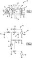
- a Bi-SQUID circuit is a circuit 71 as shown in FIG. figure 5 .
- the loop inductance 78 is mainly the inductance formed by the first portion 28 of the first branch 20 and the first portion 34 of the second branch 22 ; the inductance formed by the second portion 30 of the first leg 20 and the second portion 36 of the second leg 22 being reduced for example by reducing their lengths.
- the linearity of the circuit 71 of the figure 5 strongly depends on the value of the critical current of Josephson junction 76.
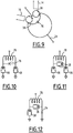
- the component described figure 7 offers the advantage of a possibility of critical current control, it is possible to modify it by using one or more SQUIDs 38 to adjust the critical current in any of the branches 20, 22 or the branch in parallel obtained with the series connection of the conductors of the first portion 28 of the first branch 20 and the first part 34 of the second branch 22) as illustrated by the figures 4 , 6, 7, 8 , 9, 10, 11, 12 .
- the figure 4 shows this change so that the critical current control is on the element in parallel with the loop inductor 78; this figure also illustrates an embodiment of the SQUID control circuit 38 in the form of a fork positioned directly above the SQUID 38, while having a low coupling coefficient with the other parts of the circuit.
- the three Josephson junctions 72, 74, 76 are each replaced by a SQUID 38.
- the middle Josephson junction 76 and another Josephson junction 72, 74 are each replaced by a SQUID 38.
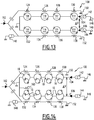
- the figure 14 presents a particular application of the superconducting component.
- the superconducting component is, for example, used in an amplifier 100 as shown in FIG. figure 13 .
- the amplifier 100 of the figure 13 is devoid of component 10 to illustrate its arrangement and operation in the absence of component 10.
- the amplifier 100 has an input 102, two outputs 104, 106, eight SQUIDs 108, 110, 112, 114, 116, 118, 120 and 122, eight inductors 124, 126, 128, 130, 132, 134, 136 and 138. respectively positioned opposite one of the eight SQUIDs 108, 110, 112, 114, 116, 118, 120 and 122, a power supply 140 of the inductors and two polarization generators 142, 144 of the eight SQUIDs 108, 110, 112, 114, 116, 118, 120 and 122.
- the circuit generating the polarizations in opposite fluxes is here shown diagrammatically, common with the coupling circuit of the input signal, but this is only a possibility, d other embodiments being conceivable.
- the potential difference ⁇ V between the two outputs 104 and 106 corresponds to an amplification of the signal sent to the input 102.
- the SQUIDs 108, 110, 112, 114, 116, 118, 120 and 122 are arranged along two lines 146, 148 which are respectively connected to the two polarization generators 142 and 144 and to the two outputs 104 and 106.
- second, third and fourth SQUIDs 108, 110, 112 and 114, from left to right on the figure 13 are arranged in series along the first line 146.
- the fifth, sixth, seventh and eighth SQUID 116, 118, 120 and 122, from left to right on the figure 13 are arranged in series along the second line 148.
- each SQUID 108, 110, 112, 114, 116, 118, 120 and 122 is mounted in a differential pair (or "doublet"), that is to say that each SQUID of the first line 146 is opposite a respective SQUID of the second line 148. More specifically, the first SQUID 108 is opposite the fifth SQUID 116, the second SQUID 110 is opposite the sixth SQUID 118, the third SQUID 112 is next to the seventh SQUID 120 and the fourth SQUID 114 is next to the eighth SQUID 122.
- This configuration is not essential to the operation of the amplifier 100.
- the eight inductors 124, 126, 128, 130, 132, 134, 136 and 138 are arranged in series along two lines, namely a third line 150 and a fourth line 152.
- the third and fourth lines 150 , 152 are connected to the input 102.
- the third line 150 is connected to a supply of the inductances to inject a flux close to ⁇ 0/4 and the fourth line 152 is connected to the supply 140 of the inductors to inject a close flow of - ⁇ 0/4 ( ⁇ 0 is the quantum of flux).
- Each of the SQUIDs 108, 110, 112, 114 has the same critical current noted I k as the SQUIDs 116, 118, 120 and 122.
- the critical current of a SQUID is the sum of the critical currents of the two Josephson junctions of the SQUID. .
- the supply 140 of the inductors is capable of causing the inductances of the third line 150 to generate a flow of polarity opposite to that generated by the inductances of the fourth line 152.
- Each of the polarization generators 142, 144 is adapted to bias each of the eight SQUIDs 108, 110, 112, 114, 116, 118, 120 and 122 with a bias current denoted I 0 .
- amplifier 100 The operation of amplifier 100 is now described.
- the operation of the amplifier 100 is based on the addition of responses of several SQUIDs (periodic), to obtain a linear transfer function, thus triangular, or any other function having a regular slope (otherwise formulated approximately constant) over a comparable range at the signal excursion.
- the transfer function is a linear rise between - ⁇ / 2 and ⁇ / 2 followed by a sinusoidal descent between ⁇ / 2 and 3 ⁇ / 2.
- a signal approaching such a triangular signal is obtained with a pair of SQUIDs mounted in differential (doublet) as shown in FIG. figure 13 .
- the bias current I 0 has to be equal to the critical current I k of the first and fifth SQUIDs 108, 116 so that this voltage ⁇ V is close to a triangular response.
- figure 14 an amplifier architecture 100 similar to that of the figure 13 in which components 10 conform to that shown on the figure 1 replace the SQUIDs.
- the amplifier 100 comprises, for each component 10, a means 160 for controlling the critical current of this component 10.
- the means 160 for controlling the critical current in the component 10 is a means for generating a magnetic flux. More specifically, the means 160 for controlling the critical current in the component 10 is an inductance connected to a generator delivering a rated current I control , the inductor being placed near the component 10.
- the superconducting component behaves like a SQUID whose critical current of one of the Josephson junctions is controllable by a control magnetic flux.
- this allows to balance the products R n * I n (the index n designates the number of the component 10 considered) of the first pair of the amplifier 100 by simple modification control magnetic flux applied.
- This balancing cancels the even harmonics of the response of the amplifier 100. It should be noted that this cancellation occurs even if the characteristics of the different components of the amplifier 100 have a dispersion.
- This principle applied to the harmonic 2 can then be applied to the second pair of components for the harmonic of order 3.
- Step by step it is thus possible to obtain a response with improved linearity for the amplifier 100.
- the amplifier 100 has improved properties in terms of harmonic distortion. Specifically, the amplifier 100, by its technology, dissipates very little power, has an extremely low noise and a very large bandwidth.
- one of the two components 10 is a DC SQUID.
Description
La présente invention concerne un composant supraconducteur. L'invention concerne également un amplificateur comportant un tel composant.The present invention relates to a superconducting component. The invention also relates to an amplifier comprising such a component.
Les composants supraconducteurs sont utilisés dans de multiples applications dont la détermination des susceptibilités magnétiques de minuscules échantillons sur une large plage de température, la détection de la résonance nucléaire magnétique et quadripolaire, la mesure de la température à l'aide de mesures de bruit également appelée thermométrie de bruit, le biomagnétisme, la géophysique, le magnétisme des roches ou le paléomagnétisme.Superconducting components are used in multiple applications including determination of magnetic susceptibilities of tiny samples over a wide temperature range, detection of magnetic and quadrupole nuclear resonance, measurement of temperature using noise measurements also called noise thermometry, biomagnetism, geophysics, rock magnetism or paleomagnetism.
Pour cela, il est fait usage de l'effet Josephson. Par définition, l'effet Josephson se manifeste par l'apparition d'un courant, également appelé supracourant, entre deux matériaux supraconducteurs séparés par une couche non supraconductrice, e.g. formée d'un matériau isolant ou métallique non supraconducteur. L'ensemble des deux matériaux supraconducteurs et de la couche est appelé une « jonction Josephson ».For this purpose, the Josephson effect is used. By definition, the Josephson effect is manifested by the appearance of a current, also called supracurrant, between two superconducting materials separated by a non-superconducting layer, e.g. formed of a non-superconducting insulating or metallic material. The set of both superconducting materials and the layer is called a "Josephson junction".
L'apparition de ce courant s'explique par la théorie macroscopique de la supraconductivité développée par John Bardeen, Leon Cooper et Robert Schrieffer. Selon cette théorie, en-dessous de la température de transition supraconductrice, au moins une partie des électrons libres dans le matériau supraconducteur sont liés entre eux, de manière à former des paires d'électrons dites « paires de Cooper ».The appearance of this current is explained by the macroscopic theory of superconductivity developed by John Bardeen, Leon Cooper and Robert Schrieffer. According to this theory, below the superconducting transition temperature, at least a portion of the free electrons in the superconducting material are bonded together so as to form so-called "Cooper pair" electron pairs.
La supraconductivité est un phénomène quantique macroscopique induisant un ordre à l'échelle macroscopique, ce qui a trois conséquences principales : une conductivité électrique infinie justifiant l'existence d'un courant permanent de paires de Cooper dans un anneau supraconducteur, la quantification du flux magnétique à travers un anneau supraconducteur résultant de l'application d'un champ magnétique et du courant induit dans l'anneau et l'effet Josephson aussi appelé effet tunnel Josephson. Pour expliquer ce dernier phénomène, considérons deux supraconducteurs séparés par une mince barrière isolante à travers laquelle les paires de Cooper peuvent passer par un effet tunnel quantique, en maintenant la cohérence de phase entre les deux supraconducteurs durant le processus. Josephson a montré que la différence δ entre les phases des fonctions d'onde des deux côtés de la jonction Josephson est en relation avec le supracourant I circulant à travers la barrière et la tension V aux bornes de la jonction Josephson, par les relations suivantes : 
- IC est le courant critique, qui est le supracourant continu maximal que peut supporter la jonction Josephson. Ce courant critique est lié à la transparence de la barrière et à la densité de paires de Cooper dans les électrodes.
- φO est le quantum de flux, qui est le rapport entre la constante de Planck et la charge électrique d'une paire de Cooper.
- I C is the critical current, which is the maximum continuous supercurrent that the Josephson junction can support. This critical current is related to the transparency of the barrier and the density of Cooper pairs in the electrodes.
- φ O is the quantum of flux, which is the ratio between the Planck constant and the electric charge of a Cooper pair.
Dans une jonction Josephson, le courant de paires de Cooper contribue au transport électronique, mais en parallèle, il existe classiquement le courant d'électrons célibataires (« quasiparticules ») associé à un terme dissipatif caractérisé par une résistance Rn . Il en résulte une équation différentielle de premier ordre en δ, qui peut se résoudre analytiquement pour donner l'évolution temporelle de δ, ce qui donne après une moyenne temporelle l'équation suivante: 
Il est souhaitable de proposer des agencements de composants supraconducteurs permettant d'exploiter au mieux l'effet Josephson.It is desirable to provide arrangements of superconducting components to exploit the best Josephson effect.
Pour cela, il est connu depuis la fin des années 60 d'utiliser un dispositif supraconducteur d'interférences quantiques, plus souvent désigné sous l'acronyme anglais SQUID, qui renvoie à « superconducting quantum interference device ».For this, it is known since the late 60s to use a superconducting quantum interference device, more often referred to as SQUID, which refers to "superconducting quantum interference device".
Un SQUID est une boucle supraconductrice (piste fermée formée d'au moins un matériau supraconducteur, électriquement équivalente à une inductance de valeur L) interrompue par au moins une couche isolante, chaque interruption formant une jonction Josephson. Les grandeurs d'inductance L de la boucle supraconductrice et du ou des courants critiques IC des jonctions Josephson sont liées par le rapport R1 entre le produit L.Ic et le quantum de flux Φ0. Ce rapport R1 est de préférence compris entre 0,2 et 4. Cela se traduit mathématiquement par les relations suivantes : ![]()
![]()
Des circuits SQUID sont aussi décrits dans les documents suivants : le document
Toutefois, l'agencement précité ne permet pas de contrôler avec précision le courant critique de la ou des jonctions Josephson utilisées dans le composant.However, the aforementioned arrangement does not allow to precisely control the critical current of the Josephson junction or junctions used in the component.
Il existe donc un besoin pour un composant supraconducteur comportant au moins une jonction Josephson dont la valeur du courant critique soit contrôlable.There is therefore a need for a superconducting component having at least one Josephson junction whose critical current value is controllable.
A cet effet, l'invention propose un composant supraconducteur comprenant une première boucle supraconductrice, la première boucle supraconductrice comportant une première branche comprenant une première jonction Josephson et une deuxième branche, la deuxième branche comprend un premier dispositif supraconducteur à interférence quantique à courant continu, le premier dispositif supraconducteur à interférence quantique à courant continu comportant une deuxième jonction Josephson et une troisième jonction Josephson, un courant critique étant défini pour chaque jonction Josephson, le courant critique de la première jonction Josephson est supérieur à la valeur absolue de la différence entre le courant critique de la troisième jonction Josephson et le courant critique de la deuxième jonction Josephson et inférieur à la somme du courant critique de la deuxième jonction Josephson et du courant critique de la troisième jonction Josephson, le composant comprenant des moyens de génération de flux magnétique sous forme de pistes conductrices positionnées au regard des branches, une piste étant couplée au premier dispositif supraconducteur à interférence quantique, les moyens de génération de flux magnétique étant agencés de façon à injecter efficacement un flux magnétique dans la première boucle supraconductrice et le premier dispositif supraconducteur à interférence quantique à courant continu.For this purpose, the invention proposes a superconducting component comprising a first superconducting loop, the first superconducting loop comprising a first branch comprising a first Josephson junction and a second branch, the second branch comprises a first superconducting device with direct-current quantum interference, the first superconducting DC quantum interference device having a second Josephson junction and a third Josephson junction, a critical current being defined for each Josephson junction, the critical current of the first Josephson junction is greater than the absolute value of the difference between the critical current of the third Josephson junction and the critical current of the second Josephson junction and less than the sum of the critical current of the second Josephson junction and the critical current of the third Josephson junction, the component comprising yens magnetic flux generation in the form of conductive tracks positioned in relation to the branches, a track being coupled to the first superconducting device with quantum interference, the magnetic flux generation means being arranged to efficiently inject a magnetic flux into the first loop superconducting device and the first superconducting DC quantum interference device.
Dans un tel cas, les moyens de génération de flux magnétique sont ainsi un moyen de contrôler le courant de boucle de façon à ajuster le courant critique du premier dispositif supraconducteur à interférence quantique à courant continu.In such a case, the magnetic flux generation means are thus a means of controlling the loop current so as to adjust the critical current of the first direct current quantum interference superconducting device.
Suivant des modes de réalisation particuliers, le composant comprend une ou plusieurs des caractéristiques suivantes, prise(s) isolément ou suivant toutes les combinaisons techniquement possibles :
- le composant comprend une quatrième jonction Josephson en parallèle avec une partie de la première branche et une partie de la deuxième branche, les deux parties formant une inductance de boucle en parallèle de la quatrième jonction Josephson.
- la deuxième branche comprend le premier dispositif supraconducteur à interférence quantique à courant continu, monté en parallèle avec une inductance de boucle formée par une partie de la première branche et une partie de la deuxième branche, l'ensemble étant monté en série avec une quatrième jonction Josephson dont le courant critique est égal au courant critique de la première jonction Josephson à 1% près. Il est possible de réaliser le composant avec un écart de courant critique plus grand que 1%, mais avec des performances réduites en terme d'amplitude de modulation.
- le composant comprend une cinquième jonction Josephson agencée pour que la première jonction Josephson et la cinquième jonction Josephson forment un deuxième dispositif supraconducteur à interférence quantique à courant continu distinct du premier dispositif supraconducteur à interférence quantique à courant continu.
- le composant comprend une cinquième jonction Josephson agencée pour que la première jonction Josephson et la cinquième jonction Josephson forment un deuxième dispositif supraconducteur à interférence quantique à courant continu distinct du premier dispositif supraconducteur à interférence quantique à courant continu, et une sixième jonction Josephson agencée pour que la quatrième jonction Josephson et la sixième jonction Josephson forment un troisième dispositif supraconducteur à interférence quantique à courant continu distinct du premier dispositif supraconducteur à interférence quantique à courant continu et du deuxième dispositif supraconducteur à interférence quantique.
- en définissant un second rapport, dont le numérateur est le produit de l'inductance de la deuxième boucle et du courant critique de la jonction équivalente au premier dispositif supraconducteur à interférence quantique à courant continu et le dénominateur est le quantum de flux, défini comme le rapport de la constante de Planck sur la charge électrique d'une paire de Cooper, le second rapport est compris entre 0,2 et 4, de préférence inférieur à 1.
- the component comprises a fourth Josephson junction in parallel with a portion of the first leg and a portion of the second leg, the two portions forming a loop inductor in parallel with the fourth Josephson junction.
- the second branch comprises the first superconducting DC quantum interference device, connected in parallel with a loop inductor formed by a part of the first branch and a part of the second branch, the assembly being connected in series with a fourth joint Josephson whose critical current is equal to the critical current of the first Josephson junction to 1%. It is possible to make the component with a critical current difference greater than 1%, but with reduced performance in terms of modulation amplitude.
- the component comprises a fifth Josephson junction arranged so that the first Josephson junction and the fifth Josephson junction form a second superconducting DC quantum interference device separate from the first DC quantum interference superconducting device.
- the component comprises a fifth Josephson junction arranged so that the first Josephson junction and the fifth Josephson junction form a second superconducting DC quantum interference device separate from the first DC quantum interference superconducting device, and a sixth Josephson junction arranged for the fourth Josephson junction and the sixth Josephson junction form a third superconducting DC quantum interference device separate from the first DC quantum interference superconducting device and the second quantum interference superconducting device.
- defining a second ratio, whose numerator is the product of the inductance of the second loop and the junction critical current equivalent to the first DC quantum interference superconducting device and the denominator is the quantum of flux, defined as the Planck constant ratio on the electrical charge of a Cooper pair, the second ratio is between 0.2 and 4, preferably less than 1.
En outre, l'invention se rapporte aussi à un amplificateur comprenant une entrée, deux sorties, la différence de potentiel entre les deux sorties correspondant à une amplification d'un signal imposé en entrée de l'amplificateur, deux premiers éléments supraconducteurs à interférence quantique, dits premier doublet, montés en différentiel et reliés chacun à une respective des sorties de l'amplificateur, les deux éléments supraconducteurs à interférence quantique du premier doublet étant choisis parmi un composant tel que précédemment décrit et un dispositif supraconducteur à interférence quantique à courant continu, ou deux composants tels que précédemment décrits, et un moyen de contrôle de la différence de flux magnétique appliqué aux deux éléments supraconducteurs à interférence quantique du premier doublet.In addition, the invention also relates to an amplifier comprising an input, two outputs, the potential difference between the two outputs corresponding to an amplification of a signal imposed at the input of the amplifier, two first superconducting elements with quantum interference , said first doublet, mounted in differential and each connected to a respective one of the outputs of the amplifier, the two superconducting elements with quantum interference of the first doublet being selected from a component as previously described and a superconducting device with DC quantum interference or two components as previously described, and a magnetic flux difference control means applied to the two quantum interference superconducting elements of the first doublet.
Suivant des modes de réalisation particuliers, l'amplificateur comprend une ou plusieurs des caractéristiques suivantes, prise(s) isolément ou suivant toutes les combinaisons techniquement possibles :
- sont interposés entre les deux premiers doublets et les deux sorties : au moins deux deuxièmes doublets comprenant deux éléments supraconducteurs à interférence quantique montés en différentiel, et reliés chacun à une respective des sorties de l'amplificateur, les deux éléments supraconducteurs à interférence quantique de chaque deuxième doublet étant choisis parmi un composant tel que décrit précédemment et un dispositif supraconducteur à interférence quantique à courant continu, ou deux composants tels que précédemment décrits, et un moyen de contrôle de la différence de flux magnétique appliqué aux deux éléments supraconducteurs à interférence quantique de chaque deuxième doublet.
- are interposed between the first two doublets and the two outputs: at least two second doublets comprising two superconducting elements with differential quantum interference, each connected to a respective one of the outputs of the amplifier, the two superconducting elements with quantum interference each second doublet being selected from a component as described above and a superconducting device with DC quantum interference, or two components as previously described, and a magnetic flux difference control means applied to the two interference superconducting elements quantum of each second doublet.
D'autres caractéristiques et avantages de l'invention apparaîtront à la lecture de la description détaillée qui suit, de modes de réalisation de l'invention, donnés à titre d'exemple uniquement et en références aux dessins qui sont :
-
figure 1 , un schéma d'implémentation d'un composant supraconducteur selon un premier mode de réalisation de l'invention ; -
figure 2 , un schéma électrique équivalent au composant selon le premier mode de réalisation ; -
figure 3 , un graphique montrant l'évolution de la phase δ des jonctions Josephson du composant selon le premier mode de réalisation en fonction du flux magnétique appliqué à la jonction Josephson ajustable ; -
figure 4 , un schéma d'implémentation d'un composant supraconducteur « Bi-SQUID » modifié correspondant à un deuxième mode de réalisation de l'invention ; -
figure 5 , un schéma électrique équivalent à un composant « Bi-SQUID » selon l'état de la technique; -
figure 6 , un schéma électrique équivalent au composant « Bi-SQUID » modifié conformément à lafigure 4 ; -
figure 7 , un schéma d'implémentation d'un composant supraconducteur selon le troisième mode de réalisation de l'invention ; -
figure 8 , un schéma électrique équivalent au composant selon le troisième mode de réalisation de l'invention ; -
figure 9 , un schéma électrique d'implémentation d'un composant supraconducteur selon un quatrième mode de réalisation de l'invention ; -
figure 10 , un schéma électrique équivalent au composant selon le quatrième mode de réalisation de l'invention ; -
figure 11 , un schéma électrique équivalent à un composant supraconducteur selon un cinquième mode de réalisation de l'invention ; -
figure 12 , un schéma électrique équivalent à un composant selon un sixième mode de réalisation de l'invention ; -
figure 13 , un schéma d'un amplificateur comprenant des SQUID ; et -
figure 14 , un schéma d'un amplificateur agencé similairement à lafigure 13 avec des composants conformes à celui de lafigure 1 à la place des SQUID.
-
figure 1 an implementation scheme of a superconducting component according to a first embodiment of the invention; -
figure 2 a circuit diagram equivalent to the component according to the first embodiment; -
figure 3 a graph showing the evolution of the δ phase of the Josephson junctions of the component according to the first embodiment as a function of the magnetic flux applied to the adjustable Josephson junction; -
figure 4 , an implementation diagram of a modified "Bi-SQUID" superconducting component corresponding to a second embodiment of the invention; -
figure 5 , a circuit diagram equivalent to a "Bi-SQUID" component according to the state of the art; -
figure 6 , a circuit diagram equivalent to the "Bi-SQUID" component modified in accordance withfigure 4 ; -
figure 7 an implementation scheme of a superconducting component according to the third embodiment of the invention; -
figure 8 a circuit diagram equivalent to the component according to the third embodiment of the invention; -
figure 9 , an electrical diagram for implementing a superconducting component according to a fourth embodiment of the invention; -
figure 10 a circuit diagram equivalent to the component according to the fourth embodiment of the invention; -
figure 11 a circuit diagram equivalent to a superconducting component according to a fifth embodiment of the invention; -
figure 12 a circuit diagram equivalent to a component according to a sixth embodiment of the invention; -
figure 13 a diagram of an amplifier comprising SQUIDs; and -
figure 14 , a diagram of an amplifier arranged similarly to thefigure 13 with components conforming to that of thefigure 1 instead of SQUID.
Un composant 10 supraconducteur est illustré sur la
Le composant 10 comporte une première boucle 12 supraconductrice, un premier moyen de couplage 14 à un flux magnétique externe, un deuxième moyen de couplage 16 à un flux magnétique externe, une première branche 20, une deuxième branche 22, des accès électriques 24 et 26 sous forme d'une entrée 24 et une sortie 26 (généralement la position de l'entrée 24 et de la sortie 26 sont relatives au sens du courant électrique), les deux branches 20, 22 étant chacune reliées à une extrémité à l'entrée 24 et à l'autre extrémité à la sortie 26.The
La première branche 20 comprend une première partie 28 formée dans un premier matériau supraconducteur S1, une deuxième partie 30 formée dans un deuxième matériau supraconducteur S2 et une première jonction Josephson 32 interposée entre les deux parties 28 et 30. La première partie 28 de la première branche 20 s'étend entre l'entrée 24 et la première jonction Josephson 32 tandis que la deuxième partie 30 de la première branche 20 s'étend entre la première jonction Josephson 32 et la sortie 26.The
Le premier matériau supraconducteur S1 de la première partie 28 de la première branche 20 est préférablement un supraconducteur à haute température critique (>26 K), du type de ceux qui sont connus sous l'abréviation YBaCuO. En variante, à la place de l'yttrium, est utilisé du néodyme, du dysprosium, de l'europium. De préférence, le supraconducteur est non métallique, et en particulier du type céramique à base d'oxyde de cuivre (ReBaCuO, où Re représente un élément chimique du type terre rare). Ces remarques s'appliquent aussi au deuxième matériau supraconducteur S2.The first superconducting material S1 of the
Selon une variante, les deux matériaux supraconducteurs S1 et S2 sont identiques, ce qui permet de faciliter la fabrication du composant 10.According to one variant, the two superconductive materials S1 and S2 are identical, which makes it easier to manufacture the
Contrairement à l'état de la technique, la deuxième branche 22 est différente de la première branche 20. Selon l'invention la deuxième branche 22 comporte une première partie 34 formée dans le premier matériau supraconducteur S1, une deuxième partie 36 formée dans le deuxième matériau supraconducteur S2 et un dispositif 38 supraconducteur à interférences quantiques noté SQUID 38 dans toute la suite de la présente description.In contrast to the state of the art, the
Le SQUID 38 est interposé entre les deux parties 34 et 36 de la deuxième branche 22. Ainsi, la première partie 34 de la deuxième branche 22 s'étend entre l'entrée 24 et le SQUID 38 tandis que la deuxième partie 36 de la deuxième branche 22 s'étend entre le SQUID 38 et la sortie 26. La branche du SQUID 38 est agencée électriquement en parallèle de la branche contenant la première jonction Josephson 32.The
Le SQUID 38 comprend une deuxième boucle 40 supraconductrice comportant une première ligne 42 et une deuxième ligne 44.The
La première ligne 42 comprend une première partie 46 formée dans le premier matériau supraconducteur S1, une deuxième partie 48 formée dans le deuxième matériau supraconducteur S2 et une deuxième jonction Josephson 50 interposée entre les deux parties 46, 48 de la première ligne 42. La première partie 46 de la première ligne 42 s'étend entre la première partie 34 de la deuxième branche 22 et la deuxième jonction Josephson 50 tandis que la deuxième partie 48 de la première ligne 42 s'étend entre la deuxième jonction Josephson 50 et la deuxième partie 36 de la deuxième branche 22.The
La deuxième ligne 44 comprend une première partie 52 réalisée dans le premier matériau supraconducteur S1, une deuxième partie 54 réalisée dans le deuxième matériau supraconducteur S2 et une troisième jonction Josephson 56 interposée entre les deux parties 52, 54 de la deuxième ligne 44 de sorte que la troisième jonction Josephson 56 est en parallèle avec la deuxième jonction Josephson 50. La première partie 52 de la deuxième ligne 44 s'étend entre la première partie 34 de la deuxième branche 22 et la troisième jonction Josephson 56 tandis que la deuxième partie 54 de la deuxième ligne 44 s'étend entre la troisième jonction Josephson 56 et la deuxième partie 36 de la deuxième branche 22.The
Le SQUID 38 sert principalement de jonction Josephson unique dont le courant critique est ajustable par un moyen « électrique » (injection de flux dans la deuxième boucle 40 supraconductrice).The
En variante, d'autres éléments non linéaires dont la caractéristique courant - tension c'est-à-dire la fonction qui permet d'exprimer le courant à partir de la tension est semblable à celle d'une jonction Josephson sont utilisés à la place des jonctions Josephson 32, 50 et 56. On appelle second rapport R2 le rapport entre le produit de l'inductance de la deuxième boucle 40 supraconductrice et du courant critique de la jonction Josephson équivalente aux deuxième jonction Josephson 50 et troisième jonction Josephson 56 et le quantum de flux Φ0. Le second rapport R2 est compris entre 0,2 et 4, de préférence inférieur à 1. Cela se traduit mathématiquement par les relations suivantes : ![]()
- L2 est l'inductance de la deuxième boucle 40 supraconductrice, et
- ICeq est le courant critique de la jonction Josephson équivalente aux deuxième jonction
Josephson 50 et troisième jonctionJosephson 56.
-
L 2 is the inductance of thesecond superconducting loop 40, and - I Ceq is the critical current of the Josephson junction equivalent to the
second Josephson junction 50 and thethird Josephson junction 56.
Selon l'exemple de la
Dans le cas de la
La première piste 58 est propre à générer un premier courant I1 dans la première boucle 12 lorsque cette première piste 58 est alimentée en courant par le premier générateur de courant 60.The
La première piste 58 sert notamment à concentrer le flux magnétique dans la boucle 12.The
En variante, le premier moyen de couplage 14 est une bobine.Alternatively, the first coupling means 14 is a coil.
En outre, le premier générateur de courant 60 peut être remplacé par tout autre générateur électrique (de tension ou d'une grandeur électrique intermédiaire entre courant et tension).In addition, the first
Selon l'exemple de la
La deuxième piste 62 est propre à générer un deuxième courant I2 dans la deuxième boucle 40 lorsque cette deuxième piste 62 est alimentée en courant par le deuxième générateur de courant 64.The
Le deuxième générateur de courant 64 peut être remplacé par tout autre générateur électrique (de tension ou d'une grandeur électrique intermédiaire entre courant et tension).The second
Selon une variante, le composant 10 est pourvu d'un seul moyen de couplage 16 pour générer un courant uniquement dans la deuxième jonction Josephson 50 et la troisième jonction Josephson 56.Alternatively, the
Par ailleurs, pour atteindre les meilleures performances, selon une autre variante, le premier courant critique IC1 de la première jonction Josephson 32 est supérieur à la valeur absolue de la différence entre le troisième courant critique IC3 de la troisième jonction Josephson 56 et le deuxième courant critique IC2 de la deuxième jonction Josephson 50 et inférieur à la somme du troisième courant critique IC3 et du deuxième courant critique IC2. Ces inégalités s'écrivent mathématiquement comme une inégalité triangulaire : ![]()
![]()
Le fonctionnement du composant 10 supraconducteur est maintenant décrit en référence à la
Dans la simulation effectuée pour la
Lorsque le flux magnétique créé par la deuxième piste 60 est proche d'un multiple du quantum de flux Φ0, le courant critique ICeq de la jonction Josephson équivalente au SQUID 38 est maximum. Le courant critique IC10 du composant 10 qui correspond au courant critique équivalent au SQUID 38 et à la première jonction Josephson est alors maximal. Le courant de polarisation injecté via l'entrée 24 et la sortie 26 du composant 10 est plus faible que le courant critique IC10 du composant 10, de sorte que les trois jonctions Josephson 32, 50 et 56 sont toutes dans un état statique, c'est-à-dire un état dans lequel la différence de potentiel de part et d'autre des jonctions Josephson 32, 50 et 56 est nulle. Dans le cas de la simulation présentée
Par contre, pour les plages de temps comprises entre 100 ps à 400 ps et entre 650 ps à 900 ps, le courant critique ICeq de la jonction Josephson équivalente au SQUID 38 (de même que pour des résistances en parallèle, il peut être défini une jonction Josephson équivalente à deux jonctions Josephson en parallèle comme dans le cas du SQUID 38) est réduit. Le courant critique IC10 du composant 10 est alors réduit. Le courant de polarisation injecté via l'entrée 24 et la sortie 26 du composant 10 est alors plus fort que le courant critique IC10 du composant 10, de sorte que les trois jonctions Josephson 32, 50 et 56 sont toutes dans un état dynamique, c'est-à-dire un état dans lequel la phase de la jonction Josephson évolue de façon monotone avec le temps.On the other hand, for time ranges between 100 ps to 400 ps and 650 ps to 900 ps, the critical current I Ceq of the Josephson junction is equivalent to SQUID 38 (as for parallel resistors, it can be defined a Josephson junction equivalent to two Josephson junctions in parallel as in the case of SQUID 38) is reduced. The critical current I C10 of
Ainsi, grâce au courant alimentant la deuxième piste 62, il est possible de régler le courant critique ICeq de la jonction Josephson équivalente au SQUID 38. De ce fait, le composant 10 supraconducteur se comporte comme un SQUID dont le courant critique peut être réduit jusqu'à zéro par un flux magnétique de contrôle, par exemple introduit par la deuxième piste 62.Thus, thanks to the current supplying the
Par rapport au SQUID à courant continu, le remplacement d'une des deux jonctions Josephson par le SQUID 38 dont la caractéristique courant - tension est ajustable permet d'obtenir un composant 10 ayant une amplitude de modulation maximale lorsque les courants critiques de la première jonction Josephson 32 et le courant critique du SQUID 38 sont égaux. Un tel composant 10 permet d'obtenir une réponse mieux contrôlée ayant notamment des applications pour des circuits amplificateurs. Plus généralement, cette propriété est utile pour toutes les applications où un très bon appariement des jonctions Josephson est souhaitable.Compared to the SQUID with direct current, the replacement of one of the two Josephson junctions by the
Selon un autre mode de réalisation tel que représenté à la
Ce montage est particulièrement avantageux puisqu'il combine les avantages de la présente invention avec ceux du circuit dit « Bi-SQUID » tel que représenté
Il peut être montré que la linéarité du circuit 71 de la
La
Lorsque le circuit électrique correspondant au mode de réalisation de la
Bien entendu, ainsi que l'illustrent les
Par exemple, comme le montrent les
Selon un autre mode de réalisation présenté aux
Selon un autre mode de réalisation illustré par la
Selon encore un autre mode de réalisation qu'illustre la
La
Le composant 10 supraconducteur est, par exemple, utilisé dans un amplificateur 100 tel que présenté à la
L'amplificateur 100 comporte une entrée 102, deux sorties 104, 106, huit SQUID 108, 110, 112, 114, 116, 118, 120 et 122, huit inductances 124, 126, 128, 130, 132, 134, 136 et 138 positionnées respectivement en regard d'un des huit SQUID 108, 110, 112, 114, 116, 118, 120 et 122, une alimentation 140 des inductances et deux générateurs de polarisation 142, 144 des huit SQUID 108, 110, 112, 114, 116, 118, 120 et 122. Par souci de simplification, le circuit générant les polarisations en flux opposées, est ici représenté schématiquement, commun avec le circuit de couplage du signal d'entrée, mais ceci n'est qu'une possibilité, d'autres modes de réalisations étant envisageables.The
La différence de potentiel ΔV entre les deux sorties 104 et 106 correspond à une amplification du signal envoyé à l'entrée 102.The potential difference ΔV between the two
Les SQUID 108, 110, 112, 114, 116, 118, 120 et 122, sont agencés selon deux lignes 146, 148 qui sont reliées respectivement aux deux générateurs de polarisation 142 et 144 ainsi qu'aux deux sorties 104 et 106. Les premier, deuxième, troisième et quatrième SQUID 108, 110, 112 et 114, de la gauche vers la droite sur la
Pour la clarté de l'exposé, chaque SQUID 108, 110, 112, 114, 116, 118, 120 et 122 est monté selon une paire en différentiel (ou « doublet »), c'est-à-dire que chaque SQUID de la première ligne 146 est en regard d'un SQUID respectif de la deuxième ligne 148. Plus précisément, le premier SQUID 108 est en regard du cinquième SQUID 116, le deuxième SQUID 110 est en regard du sixième SQUID 118, le troisième SQUID 112 est en regard du septième SQUID 120 et le quatrième SQUID 114 est en regard du huitième SQUID 122. Cette configuration n'est pas indispensable au fonctionnement de l'amplificateur 100.For the sake of clarity, each
De même que les SQUID, les huit inductances 124, 126, 128, 130, 132, 134, 136 et 138 sont agencées en série selon deux lignes, à savoir une troisième ligne 150 et une quatrième ligne 152. Les troisième et quatrième lignes 150, 152 sont reliées à l'entrée 102. La troisième ligne 150 est reliée à une alimentation des inductances pour injecter un flux proche de Φ0/4 et la quatrième ligne 152 est reliée à l'alimentation 140 des inductances pour injecter un flux proche de -Φ0/4 (Φ0 est le quantum de flux).Like the SQUIDs, the eight
Chacun des SQUID 108, 110, 112, 114, présente le même courant critique noté Ik que respectivement les SQUID 116, 118, 120 et 122. Le courant critique d'un SQUID est la somme des courants critiques des deux jonctions Josephson du SQUID.Each of the
Les première, deuxième, troisième et quatrième inductances 124, 126, 128 et 130, de la gauche vers la droite sur la
L'alimentation 140 des inductances est propre à faire générer aux inductances de la troisième ligne 150 un flux de polarité opposée à celui généré par les inductances de la quatrième ligne 152.The
Chacun des générateurs de polarisation 142, 144 est propre à polariser chacun des huit SQUID 108, 110, 112, 114, 116, 118, 120 et 122 avec un courant de polarisation noté I0.Each of the
Il est à noter que l'illustration de la
Le fonctionnement de l'amplificateur 100 est maintenant décrit.The operation of
Le fonctionnement de l'amplificateur 100 repose sur l'addition de réponses de plusieurs SQUID (périodiques), pour obtenir une fonction de transfert linéaire, donc triangulaire, ou tout autre fonction présentant une pente régulière (autrement formulé approximativement constante) sur une plage comparable à l'excursion du signal. Par exemple, la fonction de transfert est une montée linéaire entre -π/2 et π/2 suivie d'une descente sinusoïdale entre π/2 et 3π/2.The operation of the
Un signal approchant d'un tel signal triangulaire est obtenu avec une paire de SQUID monté en différentiel (doublet) comme illustré sur la
En effet, considérons la première paire de SQUID après l'entrée 102. Cette première paire de SQUID comprend le premier SQUID 108 et le cinquième SQUID 116. Ces deux SQUID 108 et 116 présentent le même courant critique Ik et sont polarisés par le courant de polarisation I0 . En outre, l'alimentation des inductances 140 impose un flux magnétique au cinquième SQUID 116 décalé de Φ0/4 par rapport au flux magnétique imposé au premier SQUID 108. La différence de potentiel entre les deux SQUID 108, 116 est donnée par : 
- δV est la différence de potentiel entre les deux
SQUID - V1 est le potentiel du
premier SQUID 108, - V5 est le potentiel du cinquième
SQUID 116, - VC1 = R1.Ik est la tension caractéristique du
premier SQUID 108, - VC5 = R5.Ik est la tension caractéristique du cinquième
SQUID 116, - ik = I0 /2Ik est le courant de polarisation normalisé au courant critique du SQUID,
- Φ1 = Φ + Φ0/4 est le flux total appliqué
au premier SQUID 108, Φ étant le flux lié au signal en entrée et - Φ5 = Φ - Φ0/4 est le flux total appliqué
au cinquième SQUID 116, Φ étant le flux lié au signal en entrée.
- δ V is the potential difference between the two
SQUIDs - V 1 is the potential of the
first SQUID 108, - V 5 is the potential of the
fifth SQUID 116, - V C1 = R 1 .I k is the characteristic voltage of the
first SQUID 108, - V C5 = R 5 .I k is the characteristic voltage of the
fifth SQUID 116, - i k = I 0 / 2I k is the normalized polarization current at the critical current of SQUID,
- Φ 1 = Φ + Φ 0/4 is the total flux applied to the
first SQUID 108, where Φ is the flow related to the input signal and - Φ 5 = Φ - Φ 0/4 is the total flux applied to the
fifth SQUID 116, where Φ is the flow related to the input signal.
Notons que le décalage de Φ0/4 n'est pas critique. Il s'agit d'un compromis entre grand gain et grande excursion du signal. Pour ik = 1 et R1 =R5 , on peut écrire δV sous la forme : ![]()
![]()
![]()
![]()
On a imposé notamment que le courant de polarisation I0 soit égal au courant critique Ik des premier et cinquième SQUID 108, 116 pour que cette tension δV soit proche d'une réponse triangulaire.In particular, the bias current I 0 has to be equal to the critical current I k of the first and
Cette condition I0 = Ik est assez difficile à satisfaire, voire impossible si les caractéristiques courant-tension des SQUID 108, 116 de la paire ont la moindre dispersion. Les courants de polarisation permettent de compenser en partie cette dispersion. Ainsi, il est possible d'équilibrer les courants de polarisations appliqués de façon à éliminer l'harmonique 2 en sortie de l'amplificateur 100. Si les produits R1.Ik et R5.Ik sont égaux, toutes les harmoniques paires peuvent être éliminées simultanément.This condition I 0 = I k is quite difficult to satisfy, if not impossible, if the current-voltage characteristics of the
Pour encore améliorer la forme triangulaire, il est possible d'utiliser d'autres paires de SQUID (trois sont représentés à titre d'exemple sur la
A l'étude de ce mode fonctionnement de l'amplificateur 100 de la
C'est pourquoi il est proposé à la
En outre, l'amplificateur 100 comprend, pour chaque composant 10, un moyen de contrôle 160 du courant critique de ce composant 10.In addition, the
Pour simplifier la
L'intérêt d'utiliser un composant 10 supraconducteur tel que proposé à la
Comme expliqué précédemment, le composant 10 supraconducteur se comporte comme un SQUID dont le courant critique de l'une des jonctions Josephson est contrôlable par un flux magnétique de contrôle. Appliqué à la première paire de composants 10 montés en différentiel, cela permet ainsi d'équilibrer les produits Rn *In (l'indice n désigne le numéro du composant 10 considéré) de la première paire de l'amplificateur 100 par simple modification du flux magnétique de contrôle appliqué. Cet équilibrage annule les harmoniques paires de la réponse de l'amplificateur 100. Il est à noter que cette annulation se produit même si les caractéristiques des différents composants 10 de l'amplificateur 100 présentent une dispersion.As explained above, the superconducting component behaves like a SQUID whose critical current of one of the Josephson junctions is controllable by a control magnetic flux. Applied to the first pair of
Ce principe appliqué à l'harmonique 2 peut s'appliquer ensuite à la deuxième paire de composants pour l'harmonique d'ordre 3.This principle applied to the harmonic 2 can then be applied to the second pair of components for the harmonic of
De proche en proche, il est ainsi possible d'obtenir une réponse avec linéarité améliorée pour l'amplificateur 100.Step by step, it is thus possible to obtain a response with improved linearity for the
Ainsi, l'amplificateur 100 présente des propriétés améliorées en termes de distorsion harmonique. Plus précisément, l'amplificateur 100, de par sa technologie, dissipe très peu de puissance, a un bruit extrêmement faible et une très grande bande passante. L'emploi du composant 10 supraconducteur proposé à la
Claims (8)
- Superconducting component (10) comprising a first superconducting loop (12), the first superconducting loop (12) comprising:• a first branch (20) comprising a first Josephson junction (32),• a second branch (22),the second branch (22) comprising a first direct-current superconducting quantum interference device (38),
the first direct-current superconducting quantum interference device (38) comprising a second Josephson junction (50) and a third Josephson junction (56), a critical current (IC1 , IC2 , IC3 ) being defined for each Josephson junction (32, 50, 56), the critical current (IC1 ) of the first Josephson junction (32) is greater than the absolute value of the difference between the critical current (IC3 ) of the third Josephson junction (56) and the critical current (IC2 ) of the second Josephson junction (50) and less than the sum of the critical current (IC2 ) of the second Josephson junction (50) and the critical current (IC3 ) of the third Josephson junction (56), characterised in that the component (10) comprises magnetic flux generating means (14, 16, 58, 60, 62, 64) in the form of conductive tracks (58, 62) positioned opposite the branches (20, 22), one track (58, 62) being coupled to the first superconducting quantum interference device (38), the magnetic flux generating means (14, 16, 58, 60, 62, 64) being arranged so as to efficiently inject a magnetic flux into the first direct-current superconducting quantum interference device (38). - Component according to claim 1, further comprising a fourth Josephson junction (76) in parallel with a portion (28) of the first branch (20) and a portion (34) of the second branch (22), the two portions (28, 34) forming a loop inductor (78) in parallel with the fourth Josephson junction (76).
- Component according to claim 1 or 2, wherein the second branch (22) comprises the first direct-current superconducting quantum interference device (38), mounted in parallel with a loop inductor (78) formed by a portion (28) of the first branch (20) and a portion (34) of the second branch (22), the assembly being mounted in series with a fourth Josephson junction (72), the critical current of which is equal to the critical current of the first Josephson junction (32), to within 1%.
- Component according to claim 2 or 3, further comprising a fifth Josephson junction arranged so that the first Josephson junction (32) and the fifth Josephson junction form a second direct-current superconducting quantum interference device distinct from the first direct-current superconducting quantum interference device (38).
- Component according to claim 3, further comprising:- a fifth Josephson junction arranged so that the first Josephson junction (32) and the fifth Josephson junction form a second direct-current superconducting quantum interference device distinct from the first direct-current superconducting quantum interference device (38), and- a sixth Josephson junction arranged so that the fourth Josephson junction and the sixth Josephson junction form a third direct-current superconducting quantum interference device distinct from the first direct-current superconducting quantum interference device (38) and from the second superconducting quantum interference device.
- Component according to any one of claims 1 to 5, wherein, in defining a second ratio (R2), in which:• the numerator is the product of the inductance of the second loop (40) and the critical current of the junction equivalent to the first direct-current superconducting quantum interference device (38), and• the denominator is the flux quantum, defined as the ratio of the Planck constant to the electric charge of a Cooper pair,the second ratio (R2) is between 0.2 and 4, preferably less than 1.
- Amplifier (100) comprising:• an input (102),• two outputs (104, 106), the potential difference between the two outputs (104, 106) corresponding to an amplification of a signal imposed at the input of the amplifier (100),• two first superconducting quantum interference elements (10, 108, 110, 112, 114, 116, 118, 120, 122), called the first doublet, mounted differentially and each connected to a respective one of the outputs (104, 106) of the amplifier (100), the two superconducting quantum interference elements of the first doublet (10, 108, 110, 112, 114, 116, 118, 120, 122) being chosen from:- a component (10) according to any one of claims 1 to 8 and a direct-current superconducting quantum interference device (108, 110, 112, 114, 116, 118, 120, 122), or- two components (10) according to any one of claims 1 to 6, and• a means (160) for controlling the difference in magnetic flux applied to the two superconducting quantum interference elements of the first doublet (10, 108, 110, 112, 114, 116, 118, 120, 122).
- Amplifier according to claim 7, wherein there are interposed between the two first doublets (10, 108, 110, 112, 114, 116, 118, 120, 122) and the two outputs:• at least two second doublets comprising two superconducting quantum interference elements (10, 108, 110, 112, 114, 116, 118, 120, 122) mounted differentially and each connected to a respective one of the outputs (104, 106) of the amplifier (100), the two superconducting quantum interference elements of each second doublet (10, 108, 110, 112, 114, 116, 118, 120, 122) being chosen from:- a component (10) according to any one of claims 1 to 8 and a direct-current superconducting quantum interference device (108, 110, 112, 114, 116, 118, 120, 122), or- two components (10) according to any one of claims 1 to 6, and• a means (160) for controlling the difference in magnetic flux applied to the two superconducting quantum interference elements (10, 108, 110, 112, 114, 116, 118, 120, 122) of each second doublet.
Applications Claiming Priority (2)
| Application Number | Priority Date | Filing Date | Title |
|---|---|---|---|
| FR1401080A FR3021118B1 (en) | 2014-05-13 | 2014-05-13 | SUPERCONDUCTING COMPONENT, AMPLIFIER |
| PCT/EP2015/060692 WO2015173354A1 (en) | 2014-05-13 | 2015-05-13 | Superconducting component and associated amplifier |
Publications (2)
| Publication Number | Publication Date |
|---|---|
| EP3143419A1 EP3143419A1 (en) | 2017-03-22 |
| EP3143419B1 true EP3143419B1 (en) | 2019-09-18 |
Family
ID=51659670
Family Applications (1)
| Application Number | Title | Priority Date | Filing Date |
|---|---|---|---|
| EP15723017.8A Active EP3143419B1 (en) | 2014-05-13 | 2015-05-13 | Superconducting component and associated amplifier |
Country Status (3)
| Country | Link |
|---|---|
| EP (1) | EP3143419B1 (en) |
| FR (1) | FR3021118B1 (en) |
| WO (1) | WO2015173354A1 (en) |
Families Citing this family (1)
| Publication number | Priority date | Publication date | Assignee | Title |
|---|---|---|---|---|
| CN112539849B (en) * | 2020-11-19 | 2022-06-28 | 中国科学院上海微系统与信息技术研究所 | Quantum interference detection chip and test system thereof |
Family Cites Families (8)
| Publication number | Priority date | Publication date | Assignee | Title |
|---|---|---|---|---|
| US4051393A (en) * | 1976-12-16 | 1977-09-27 | Bell Telephone Laboratories, Incorporated | Current switched josephson junction memory and logic circuits |
| US4149097A (en) * | 1977-12-30 | 1979-04-10 | International Business Machines Corporation | Waveform transition sensitive Josephson junction circuit having sense bus and logic applications |
| JPS57132072A (en) * | 1981-02-09 | 1982-08-16 | Tohoku Metal Ind Ltd | Absolute fluxmeter of superconduction quantum interference |
| JP3144973B2 (en) * | 1993-12-20 | 2001-03-12 | 株式会社日立製作所 | Digital SQUID and measurement system using the same |
| US5574290A (en) * | 1994-02-23 | 1996-11-12 | Micontech, Inc. | Superconducting quantum interference device |
| JP3655753B2 (en) * | 1998-10-07 | 2005-06-02 | 日本電気株式会社 | Superconducting current measuring circuit and current measuring device using it |
| DE50004918D1 (en) * | 1999-10-04 | 2004-02-05 | Qest Quantenelektronische Syst | DEVICE FOR HIGH-RESOLUTION MEASUREMENT OF MAGNETIC FIELDS |
| CA3029935A1 (en) * | 2008-10-09 | 2010-04-15 | D-Wave Systems Inc. | Systems, methods and apparatus for measuring magnetic fields |
-
2014
- 2014-05-13 FR FR1401080A patent/FR3021118B1/en not_active Expired - Fee Related
-
2015
- 2015-05-13 WO PCT/EP2015/060692 patent/WO2015173354A1/en active Application Filing
- 2015-05-13 EP EP15723017.8A patent/EP3143419B1/en active Active
Non-Patent Citations (1)
| Title |
|---|
| None * |
Also Published As
| Publication number | Publication date |
|---|---|
| EP3143419A1 (en) | 2017-03-22 |
| FR3021118A1 (en) | 2015-11-20 |
| FR3021118B1 (en) | 2018-03-16 |
| WO2015173354A1 (en) | 2015-11-19 |
Similar Documents
| Publication | Publication Date | Title |
|---|---|---|
| Yasuda et al. | Nonreciprocal charge transport at topological insulator/superconductor interface | |
| Senapati et al. | Spin-filter Josephson junctions | |
| Sekimoto et al. | Continuous 30 μW terahertz source by a high-Tc superconductor mesa structure | |
| Nakata et al. | Robust charge-density wave strengthened by electron correlations in monolayer 1T-TaSe2 and 1T-NbSe2 | |
| WO2003094250A2 (en) | Superconducting quantum bit device with josephson junctions | |
| CA2095964C (en) | Hall-effect sensor | |
| FR2595509A1 (en) | COMPONENT IN SEMICONDUCTOR MATERIAL EPITAXIA ON A SUBSTRATE WITH DIFFERENT MESH PARAMETER AND APPLICATION TO VARIOUS SEMICONDUCTOR COMPONENTS | |
| Jabdaraghi et al. | Non-hysteretic superconducting quantum interference proximity transistor with enhanced responsivity | |
| EP2543135B1 (en) | Magnetoresistive radiofrequency oscillator and method for generating an oscillating signal | |
| EP3143419B1 (en) | Superconducting component and associated amplifier | |
| Zhang et al. | Josephson effect between electron-doped and hole-doped iron pnictide single crystals | |
| EP2543134B1 (en) | Magnetoresistive radiofrequency oscillator and method for generating an oscillating signal | |
| McCaughan et al. | nanoSQUID operation using kinetic rather than magnetic induction | |
| Kato et al. | Electron spin interferometry using a semiconductor ring structure | |
| FR3056041B1 (en) | ADAPTATION CIRCUIT FOR LOW NOISE AMPLIFIER AND LOW NOISE AMPLIFIER INCLUDING SUCH A CIRCUIT | |
| Baba et al. | Superconducting transport in single and parallel double InAs quantum dot Josephson junctions with Nb-based superconducting electrodes | |
| EP3350842B1 (en) | Photodetector with reduced dark current | |
| EP2834658B1 (en) | Method and device for measuring a magnetic field and the temperature of a magneto-resistive transducer | |
| EP3143692B1 (en) | Mixer circuit with compensable harmonic content | |
| Joshi et al. | Superconducting properties of NbN film, bridge and meanders | |
| Lee et al. | Role of spin Hall effect in the topological side surface conduction | |
| EP3278128A1 (en) | Isolated dc current and voltage sensor with low crosstalk | |
| EP3143694A1 (en) | Logic circuit based on spin valves of the spin-polarized supercurrent type and circuit integrating such logic gates | |
| FR2969425A1 (en) | OSCILLATING CIRCUIT HAVING MAGNETIC RESISTANCE EFFECT | |
| Akushichi et al. | Spin accumulation in Si channels using CoFe/MgO/Si and CoFe/AlOx/Si tunnel contacts with high quality tunnel barriers prepared by radical-oxygen annealing |
Legal Events
| Date | Code | Title | Description |
|---|---|---|---|
| STAA | Information on the status of an ep patent application or granted ep patent |
Free format text: STATUS: THE INTERNATIONAL PUBLICATION HAS BEEN MADE |
|
| PUAI | Public reference made under article 153(3) epc to a published international application that has entered the european phase |
Free format text: ORIGINAL CODE: 0009012 |
|
| STAA | Information on the status of an ep patent application or granted ep patent |
Free format text: STATUS: REQUEST FOR EXAMINATION WAS MADE |
|
| 17P | Request for examination filed |
Effective date: 20161114 |
|
| AK | Designated contracting states |
Kind code of ref document: A1 Designated state(s): AL AT BE BG CH CY CZ DE DK EE ES FI FR GB GR HR HU IE IS IT LI LT LU LV MC MK MT NL NO PL PT RO RS SE SI SK SM TR |
|
| AX | Request for extension of the european patent |
Extension state: BA ME |
|
| DAV | Request for validation of the european patent (deleted) | ||
| DAX | Request for extension of the european patent (deleted) | ||
| STAA | Information on the status of an ep patent application or granted ep patent |
Free format text: STATUS: EXAMINATION IS IN PROGRESS |
|
| 17Q | First examination report despatched |
Effective date: 20180227 |
|
| 17Q | First examination report despatched |
Effective date: 20181009 |
|
| GRAP | Despatch of communication of intention to grant a patent |
Free format text: ORIGINAL CODE: EPIDOSNIGR1 |
|
| STAA | Information on the status of an ep patent application or granted ep patent |
Free format text: STATUS: GRANT OF PATENT IS INTENDED |
|
| INTG | Intention to grant announced |
Effective date: 20190417 |
|
| GRAS | Grant fee paid |
Free format text: ORIGINAL CODE: EPIDOSNIGR3 |
|
| GRAA | (expected) grant |
Free format text: ORIGINAL CODE: 0009210 |
|
| STAA | Information on the status of an ep patent application or granted ep patent |
Free format text: STATUS: THE PATENT HAS BEEN GRANTED |
|
| AK | Designated contracting states |
Kind code of ref document: B1 Designated state(s): AL AT BE BG CH CY CZ DE DK EE ES FI FR GB GR HR HU IE IS IT LI LT LU LV MC MK MT NL NO PL PT RO RS SE SI SK SM TR |
|
| REG | Reference to a national code |
Ref country code: GB Ref legal event code: FG4D Free format text: NOT ENGLISH |
|
| REG | Reference to a national code |
Ref country code: CH Ref legal event code: EP |
|
| REG | Reference to a national code |
Ref country code: DE Ref legal event code: R096 Ref document number: 602015038197 Country of ref document: DE |
|
| REG | Reference to a national code |
Ref country code: AT Ref legal event code: REF Ref document number: 1181980 Country of ref document: AT Kind code of ref document: T Effective date: 20191015 |
|
| REG | Reference to a national code |
Ref country code: IE Ref legal event code: FG4D Free format text: LANGUAGE OF EP DOCUMENT: FRENCH |
|
| REG | Reference to a national code |
Ref country code: NL Ref legal event code: MP Effective date: 20190918 |
|
| PG25 | Lapsed in a contracting state [announced via postgrant information from national office to epo] |
Ref country code: SE Free format text: LAPSE BECAUSE OF FAILURE TO SUBMIT A TRANSLATION OF THE DESCRIPTION OR TO PAY THE FEE WITHIN THE PRESCRIBED TIME-LIMIT Effective date: 20190918 Ref country code: NO Free format text: LAPSE BECAUSE OF FAILURE TO SUBMIT A TRANSLATION OF THE DESCRIPTION OR TO PAY THE FEE WITHIN THE PRESCRIBED TIME-LIMIT Effective date: 20191218 Ref country code: BG Free format text: LAPSE BECAUSE OF FAILURE TO SUBMIT A TRANSLATION OF THE DESCRIPTION OR TO PAY THE FEE WITHIN THE PRESCRIBED TIME-LIMIT Effective date: 20191218 Ref country code: HR Free format text: LAPSE BECAUSE OF FAILURE TO SUBMIT A TRANSLATION OF THE DESCRIPTION OR TO PAY THE FEE WITHIN THE PRESCRIBED TIME-LIMIT Effective date: 20190918 Ref country code: FI Free format text: LAPSE BECAUSE OF FAILURE TO SUBMIT A TRANSLATION OF THE DESCRIPTION OR TO PAY THE FEE WITHIN THE PRESCRIBED TIME-LIMIT Effective date: 20190918 Ref country code: LT Free format text: LAPSE BECAUSE OF FAILURE TO SUBMIT A TRANSLATION OF THE DESCRIPTION OR TO PAY THE FEE WITHIN THE PRESCRIBED TIME-LIMIT Effective date: 20190918 |
|
| REG | Reference to a national code |
Ref country code: LT Ref legal event code: MG4D |
|
| PG25 | Lapsed in a contracting state [announced via postgrant information from national office to epo] |
Ref country code: LV Free format text: LAPSE BECAUSE OF FAILURE TO SUBMIT A TRANSLATION OF THE DESCRIPTION OR TO PAY THE FEE WITHIN THE PRESCRIBED TIME-LIMIT Effective date: 20190918 Ref country code: RS Free format text: LAPSE BECAUSE OF FAILURE TO SUBMIT A TRANSLATION OF THE DESCRIPTION OR TO PAY THE FEE WITHIN THE PRESCRIBED TIME-LIMIT Effective date: 20190918 Ref country code: GR Free format text: LAPSE BECAUSE OF FAILURE TO SUBMIT A TRANSLATION OF THE DESCRIPTION OR TO PAY THE FEE WITHIN THE PRESCRIBED TIME-LIMIT Effective date: 20191219 Ref country code: AL Free format text: LAPSE BECAUSE OF FAILURE TO SUBMIT A TRANSLATION OF THE DESCRIPTION OR TO PAY THE FEE WITHIN THE PRESCRIBED TIME-LIMIT Effective date: 20190918 |
|
| REG | Reference to a national code |
Ref country code: AT Ref legal event code: MK05 Ref document number: 1181980 Country of ref document: AT Kind code of ref document: T Effective date: 20190918 |
|
| PG25 | Lapsed in a contracting state [announced via postgrant information from national office to epo] |
Ref country code: ES Free format text: LAPSE BECAUSE OF FAILURE TO SUBMIT A TRANSLATION OF THE DESCRIPTION OR TO PAY THE FEE WITHIN THE PRESCRIBED TIME-LIMIT Effective date: 20190918 Ref country code: NL Free format text: LAPSE BECAUSE OF FAILURE TO SUBMIT A TRANSLATION OF THE DESCRIPTION OR TO PAY THE FEE WITHIN THE PRESCRIBED TIME-LIMIT Effective date: 20190918 Ref country code: PL Free format text: LAPSE BECAUSE OF FAILURE TO SUBMIT A TRANSLATION OF THE DESCRIPTION OR TO PAY THE FEE WITHIN THE PRESCRIBED TIME-LIMIT Effective date: 20190918 Ref country code: RO Free format text: LAPSE BECAUSE OF FAILURE TO SUBMIT A TRANSLATION OF THE DESCRIPTION OR TO PAY THE FEE WITHIN THE PRESCRIBED TIME-LIMIT Effective date: 20190918 Ref country code: PT Free format text: LAPSE BECAUSE OF FAILURE TO SUBMIT A TRANSLATION OF THE DESCRIPTION OR TO PAY THE FEE WITHIN THE PRESCRIBED TIME-LIMIT Effective date: 20200120 Ref country code: IT Free format text: LAPSE BECAUSE OF FAILURE TO SUBMIT A TRANSLATION OF THE DESCRIPTION OR TO PAY THE FEE WITHIN THE PRESCRIBED TIME-LIMIT Effective date: 20190918 Ref country code: EE Free format text: LAPSE BECAUSE OF FAILURE TO SUBMIT A TRANSLATION OF THE DESCRIPTION OR TO PAY THE FEE WITHIN THE PRESCRIBED TIME-LIMIT Effective date: 20190918 Ref country code: AT Free format text: LAPSE BECAUSE OF FAILURE TO SUBMIT A TRANSLATION OF THE DESCRIPTION OR TO PAY THE FEE WITHIN THE PRESCRIBED TIME-LIMIT Effective date: 20190918 |
|
| PG25 | Lapsed in a contracting state [announced via postgrant information from national office to epo] |
Ref country code: IS Free format text: LAPSE BECAUSE OF FAILURE TO SUBMIT A TRANSLATION OF THE DESCRIPTION OR TO PAY THE FEE WITHIN THE PRESCRIBED TIME-LIMIT Effective date: 20200224 Ref country code: SM Free format text: LAPSE BECAUSE OF FAILURE TO SUBMIT A TRANSLATION OF THE DESCRIPTION OR TO PAY THE FEE WITHIN THE PRESCRIBED TIME-LIMIT Effective date: 20190918 Ref country code: CZ Free format text: LAPSE BECAUSE OF FAILURE TO SUBMIT A TRANSLATION OF THE DESCRIPTION OR TO PAY THE FEE WITHIN THE PRESCRIBED TIME-LIMIT Effective date: 20190918 Ref country code: SK Free format text: LAPSE BECAUSE OF FAILURE TO SUBMIT A TRANSLATION OF THE DESCRIPTION OR TO PAY THE FEE WITHIN THE PRESCRIBED TIME-LIMIT Effective date: 20190918 |
|
| REG | Reference to a national code |
Ref country code: DE Ref legal event code: R097 Ref document number: 602015038197 Country of ref document: DE |
|
| PLBE | No opposition filed within time limit |
Free format text: ORIGINAL CODE: 0009261 |
|
| STAA | Information on the status of an ep patent application or granted ep patent |
Free format text: STATUS: NO OPPOSITION FILED WITHIN TIME LIMIT |
|
| PG2D | Information on lapse in contracting state deleted |
Ref country code: IS |
|
| PG25 | Lapsed in a contracting state [announced via postgrant information from national office to epo] |
Ref country code: DK Free format text: LAPSE BECAUSE OF FAILURE TO SUBMIT A TRANSLATION OF THE DESCRIPTION OR TO PAY THE FEE WITHIN THE PRESCRIBED TIME-LIMIT Effective date: 20190918 Ref country code: IS Free format text: LAPSE BECAUSE OF FAILURE TO SUBMIT A TRANSLATION OF THE DESCRIPTION OR TO PAY THE FEE WITHIN THE PRESCRIBED TIME-LIMIT Effective date: 20200119 |
|
| 26N | No opposition filed |
Effective date: 20200619 |
|
| PG25 | Lapsed in a contracting state [announced via postgrant information from national office to epo] |
Ref country code: SI Free format text: LAPSE BECAUSE OF FAILURE TO SUBMIT A TRANSLATION OF THE DESCRIPTION OR TO PAY THE FEE WITHIN THE PRESCRIBED TIME-LIMIT Effective date: 20190918 |
|
| PG25 | Lapsed in a contracting state [announced via postgrant information from national office to epo] |
Ref country code: CH Free format text: LAPSE BECAUSE OF NON-PAYMENT OF DUE FEES Effective date: 20200531 Ref country code: MC Free format text: LAPSE BECAUSE OF FAILURE TO SUBMIT A TRANSLATION OF THE DESCRIPTION OR TO PAY THE FEE WITHIN THE PRESCRIBED TIME-LIMIT Effective date: 20190918 Ref country code: LI Free format text: LAPSE BECAUSE OF NON-PAYMENT OF DUE FEES Effective date: 20200531 |
|
| REG | Reference to a national code |
Ref country code: BE Ref legal event code: MM Effective date: 20200531 |
|
| GBPC | Gb: european patent ceased through non-payment of renewal fee |
Effective date: 20200513 |
|
| PG25 | Lapsed in a contracting state [announced via postgrant information from national office to epo] |
Ref country code: LU Free format text: LAPSE BECAUSE OF NON-PAYMENT OF DUE FEES Effective date: 20200513 |
|
| PG25 | Lapsed in a contracting state [announced via postgrant information from national office to epo] |
Ref country code: GB Free format text: LAPSE BECAUSE OF NON-PAYMENT OF DUE FEES Effective date: 20200513 Ref country code: IE Free format text: LAPSE BECAUSE OF NON-PAYMENT OF DUE FEES Effective date: 20200513 |
|
| PG25 | Lapsed in a contracting state [announced via postgrant information from national office to epo] |
Ref country code: BE Free format text: LAPSE BECAUSE OF NON-PAYMENT OF DUE FEES Effective date: 20200531 |
|
| PG25 | Lapsed in a contracting state [announced via postgrant information from national office to epo] |
Ref country code: TR Free format text: LAPSE BECAUSE OF FAILURE TO SUBMIT A TRANSLATION OF THE DESCRIPTION OR TO PAY THE FEE WITHIN THE PRESCRIBED TIME-LIMIT Effective date: 20190918 Ref country code: MT Free format text: LAPSE BECAUSE OF FAILURE TO SUBMIT A TRANSLATION OF THE DESCRIPTION OR TO PAY THE FEE WITHIN THE PRESCRIBED TIME-LIMIT Effective date: 20190918 Ref country code: CY Free format text: LAPSE BECAUSE OF FAILURE TO SUBMIT A TRANSLATION OF THE DESCRIPTION OR TO PAY THE FEE WITHIN THE PRESCRIBED TIME-LIMIT Effective date: 20190918 |
|
| PG25 | Lapsed in a contracting state [announced via postgrant information from national office to epo] |
Ref country code: MK Free format text: LAPSE BECAUSE OF FAILURE TO SUBMIT A TRANSLATION OF THE DESCRIPTION OR TO PAY THE FEE WITHIN THE PRESCRIBED TIME-LIMIT Effective date: 20190918 |
|
| PGFP | Annual fee paid to national office [announced via postgrant information from national office to epo] |
Ref country code: FR Payment date: 20230523 Year of fee payment: 9 Ref country code: DE Payment date: 20230510 Year of fee payment: 9 |