EP3143419B1 - Supraleitendes bauelement und zugehöriger verstärker - Google Patents
Supraleitendes bauelement und zugehöriger verstärker Download PDFInfo
- Publication number
- EP3143419B1 EP3143419B1 EP15723017.8A EP15723017A EP3143419B1 EP 3143419 B1 EP3143419 B1 EP 3143419B1 EP 15723017 A EP15723017 A EP 15723017A EP 3143419 B1 EP3143419 B1 EP 3143419B1
- Authority
- EP
- European Patent Office
- Prior art keywords
- josephson junction
- quantum interference
- current
- superconducting quantum
- superconducting
- Prior art date
- Legal status (The legal status is an assumption and is not a legal conclusion. Google has not performed a legal analysis and makes no representation as to the accuracy of the status listed.)
- Active
Links
Images


Classifications
-
- G—PHYSICS
- G01—MEASURING; TESTING
- G01R—MEASURING ELECTRIC VARIABLES; MEASURING MAGNETIC VARIABLES
- G01R33/00—Arrangements or instruments for measuring magnetic variables
- G01R33/02—Measuring direction or magnitude of magnetic fields or magnetic flux
- G01R33/035—Measuring direction or magnitude of magnetic fields or magnetic flux using superconductive devices
-
- G—PHYSICS
- G01—MEASURING; TESTING
- G01R—MEASURING ELECTRIC VARIABLES; MEASURING MAGNETIC VARIABLES
- G01R31/00—Arrangements for testing electric properties; Arrangements for locating electric faults; Arrangements for electrical testing characterised by what is being tested not provided for elsewhere
- G01R31/28—Testing of electronic circuits, e.g. by signal tracer
- G01R31/302—Contactless testing
- G01R31/312—Contactless testing by capacitive methods
-
- H—ELECTRICITY
- H03—ELECTRONIC CIRCUITRY
- H03F—AMPLIFIERS
- H03F19/00—Amplifiers using superconductivity effects
Definitions
- the present invention relates to a superconducting component.
- the invention also relates to an amplifier comprising such a component.
- Superconducting components are used in multiple applications including determination of magnetic susceptibilities of tiny samples over a wide temperature range, detection of magnetic and quadrupole nuclear resonance, measurement of temperature using noise measurements also called noise thermometry, biomagnetism, geophysics, rock magnetism or paleomagnetism.
- the Josephson effect is used.
- the Josephson effect is manifested by the appearance of a current, also called supracurrant, between two superconducting materials separated by a non-superconducting layer, e.g. formed of a non-superconducting insulating or metallic material.
- the set of both superconducting materials and the layer is called a "Josephson junction".
- a SQUID is a superconducting loop (closed track formed of at least one superconducting material, electrically equivalent to an inductance of value L) interrupted by at least one insulating layer, each interruption forming a Josephson junction.
- the inductance quantities L of the superconducting loop and the critical currents I C of the Josephson junctions are linked by the ratio R1 between the product L.Ic and the quantum of flux ⁇ 0 .
- the aforementioned arrangement does not allow to precisely control the critical current of the Josephson junction or junctions used in the component.
- the invention proposes a superconducting component comprising a first superconducting loop, the first superconducting loop comprising a first branch comprising a first Josephson junction and a second branch, the second branch comprises a first superconducting device with direct-current quantum interference, the first superconducting DC quantum interference device having a second Josephson junction and a third Josephson junction, a critical current being defined for each Josephson junction, the critical current of the first Josephson junction is greater than the absolute value of the difference between the critical current of the third Josephson junction and the critical current of the second Josephson junction and less than the sum of the critical current of the second Josephson junction and the critical current of the third Josephson junction, the component comprising yens magnetic flux generation in the form of conductive tracks positioned in relation to the branches, a track being coupled to the first superconducting device with quantum interference, the magnetic flux generation means being arranged to efficiently inject a magnetic flux into the first loop superconducting device and the first superconducting DC quantum interference device.
- the magnetic flux generation means are thus a means of controlling the loop current so as to adjust the critical current of the first direct current quantum interference superconducting device.
- the invention also relates to an amplifier comprising an input, two outputs, the potential difference between the two outputs corresponding to an amplification of a signal imposed at the input of the amplifier, two first superconducting elements with quantum interference , said first doublet, mounted in differential and each connected to a respective one of the outputs of the amplifier, the two superconducting elements with quantum interference of the first doublet being selected from a component as previously described and a superconducting device with DC quantum interference or two components as previously described, and a magnetic flux difference control means applied to the two quantum interference superconducting elements of the first doublet.
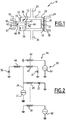
- a superconducting component is illustrated on the figure 1 .
- the component 10 comprises a first superconducting loop 12, a first coupling means 14 to an external magnetic flux, a second coupling means 16 to an external magnetic flux, a first branch 20, a second branch 22, electrical access 24 and 26 in the form of an input 24 and an output 26 (generally the position of the input 24 and the output 26 are relative to the direction of the electric current), the two branches 20, 22 being each connected to one end at the input 24 and at the other end at Exit 26.
- the first branch 20 comprises a first part 28 formed in a first superconducting material S1, a second part 30 formed in a second superconducting material S2 and a first Josephson junction 32 interposed between the two parts 28 and 30.
- the first part 28 of the first part branch 20 extends between the inlet 24 and the first Josephson junction 32 while the second portion 30 of the first branch 20 extends between the first Josephson junction 32 and the outlet 26.
- the first superconducting material S1 of the first portion 28 of the first branch 20 is preferably a high critical temperature superconductor (> 26 K), of the type of those known by the abbreviation YBaCuO.
- YBaCuO high critical temperature superconductor
- the superconductor is non-metallic, and in particular of the ceramic type based on copper oxide (ReBaCuO, where Re represents a chemical element of the rare earth type).
- the two superconductive materials S1 and S2 are identical, which makes it easier to manufacture the component 10.
- the second branch 22 is different from the first branch 20.
- the second branch 22 comprises a first portion 34 formed in the first superconducting material S1, a second portion 36 formed in the second S2 superconducting material and a quantum interference superconducting device 38 noted SQUID 38 throughout the rest of this description.
- the SQUID 38 is interposed between the two parts 34 and 36 of the second branch 22.
- the first portion 34 of the second branch 22 extends between the inlet 24 and the SQUID 38 while the second portion 36 of the second branch 22 extends between the SQUID 38 and the output 26.
- the branch of the SQUID 38 is electrically arranged in parallel with the branch containing the first Josephson junction 32.
- the SQUID 38 comprises a second superconducting loop 40 having a first line 42 and a second line 44.
- the first line 42 comprises a first portion 46 formed in the first superconducting material S1, a second portion 48 formed in the second superconducting material S2 and a second Josephson junction 50 interposed between the two parts 46, 48 of the first line 42.
- portion 46 of the first line 42 extends between the first portion 34 of the second leg 22 and the second Josephson junction 50 while the second portion 48 of the first line 42 extends between the second Josephson junction 50 and the second portion 36 of the second branch 22.
- the second line 44 comprises a first part 52 made in the first superconducting material S1, a second part 54 made in the second superconducting material S2 and a third Josephson junction 56 interposed between the two parts 52, 54 of the second line 44 so that the third Josephson junction 56 is in parallel with the second Josephson junction 50.
- the first portion 52 of the second line 44 extends between the first portion 34 of the second branch 22 and the third Josephson junction 56 while the second portion 54 of the second the second line 44 extends between the third Josephson junction 56 and the second portion 36 of the second branch 22.
- the SQUID 38 serves mainly as a single Josephson junction whose critical current is adjustable by an "electrical" means (injection of flux in the second superconducting loop 40).
- the first coupling means 14 is in the form of a first track 58.
- the first track 58 is a conductive track connected to a first current generator 60 shown in FIG. figure 2 .
- the first track 58 is opposite the first branch 20, positioned to effectively inject a magnetic flux into the first loop 12.
- the first track 58 is able to generate a first current I1 in the first loop 12 when this first track 58 is supplied with current by the first current generator 60.
- the first track 58 serves in particular to concentrate the magnetic flux in the loop 12.
- the first coupling means 14 is a coil.
- first current generator 60 can be replaced by any other electrical generator (voltage or an electrical quantity intermediate between current and voltage).
- the second coupling means 16 is in the form of a second track 62 coupled to the SQUID 38.
- the second track 62 is a conductive track connected to a second current generator 64 visible on the figure 2 .
- the second track 62 is opposite the lines 42 and / or 44 so as to efficiently inject a magnetic flux into the second loop 40.
- the second track 62 is capable of generating a second current I2 in the second loop 40 when this second track 62 is supplied with current by the second current generator 64.
- the second current generator 64 may be replaced by any other electrical generator (of voltage or of an electrical quantity intermediate between current and voltage).
- the component 10 is provided with a single coupling means 16 for generating a current only in the second Josephson junction 50 and the third Josephson junction 56.
- the first critical current I C1 of the first Josephson junction 32 is greater than the absolute value of the difference between the third critical current I C3 of the third Josephson junction 56 and the second second critical current I C2 of the second junction Josephson 50 and less than the sum of the third critical current I C3 and the second critical current I C2 .
- the values of 100 ⁇ A (microamperes), 60 ⁇ A and 80 ⁇ A were respectively chosen for the first critical current I C1 of the first Josephson junction 32, the second critical current I C2 of the second Josephson junction 50 and the third critical current I C3 of the third Josephson junction 56.
- the second track 60 is supplied with a current increasing from 0 to 400 ⁇ A, a time-proportional magnetic flux is generated in the SQUID 38.
- the critical current I Ceq of the Josephson junction equivalent to SQUID 38 is maximum.
- the critical current I C10 of component 10 which corresponds to the critical current equivalent to SQUID 38 and the first Josephson junction is then maximal.
- the bias current injected via the input 24 and the output 26 of the component 10 is smaller than the critical current I C10 of the component 10, so that the three Josephson junctions 32, 50 and 56 are all in a static state, c that is, a state in which the potential difference across the Josephson junctions 32, 50, and 56 is zero. In the case of the simulation presented figure 3 this effect is observed over the time ranges between 0 and 100 picoseconds (ps) and between 400 ps and 650 ps.
- the critical current I Ceq of the Josephson junction is equivalent to SQUID 38 (as for parallel resistors, it can be defined a Josephson junction equivalent to two Josephson junctions in parallel as in the case of SQUID 38) is reduced.
- the critical current I C10 of component 10 is then reduced.
- the bias current injected via the input 24 and the output 26 of the component 10 is then stronger than the critical current I C10 of the component 10, so that the three Josephson junctions 32, 50 and 56 are all in a dynamic state, that is, a state in which the phase of the Josephson junction evolves monotonically with time.
- the superconducting component 10 behaves like a SQUID whose critical current can be reduced. to zero by a control magnetic flux, for example introduced by the second track 62.
- the replacement of one of the two Josephson junctions by the SQUID 38 whose current-voltage characteristic is adjustable makes it possible to obtain a component 10 having a maximum modulation amplitude when the critical currents of the first junction Josephson 32 and the critical current of SQUID 38 are equal.
- Such a component 10 provides a better controlled response including applications for amplifier circuits. More generally, this property is useful for all applications where a very good pairing of Josephson junctions is desirable.
- the superconducting component comprises the same elements as the component 10 according to the first embodiment. Only the differences are highlighted.
- a fourth Josephson junction 76 is added in parallel with the serialization of the first portion 28 of the first branch 20 and the first portion 34 of the second branch 22.
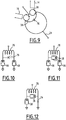
- a Bi-SQUID circuit is a circuit 71 as shown in FIG. figure 5 .
- the loop inductance 78 is mainly the inductance formed by the first portion 28 of the first branch 20 and the first portion 34 of the second branch 22 ; the inductance formed by the second portion 30 of the first leg 20 and the second portion 36 of the second leg 22 being reduced for example by reducing their lengths.
- the linearity of the circuit 71 of the figure 5 strongly depends on the value of the critical current of Josephson junction 76.
- the component described figure 7 offers the advantage of a possibility of critical current control, it is possible to modify it by using one or more SQUIDs 38 to adjust the critical current in any of the branches 20, 22 or the branch in parallel obtained with the series connection of the conductors of the first portion 28 of the first branch 20 and the first part 34 of the second branch 22) as illustrated by the figures 4 , 6, 7, 8 , 9, 10, 11, 12 .
- the figure 4 shows this change so that the critical current control is on the element in parallel with the loop inductor 78; this figure also illustrates an embodiment of the SQUID control circuit 38 in the form of a fork positioned directly above the SQUID 38, while having a low coupling coefficient with the other parts of the circuit.
- the three Josephson junctions 72, 74, 76 are each replaced by a SQUID 38.
- the middle Josephson junction 76 and another Josephson junction 72, 74 are each replaced by a SQUID 38.
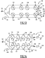
- the figure 14 presents a particular application of the superconducting component.
- the superconducting component is, for example, used in an amplifier 100 as shown in FIG. figure 13 .
- the amplifier 100 of the figure 13 is devoid of component 10 to illustrate its arrangement and operation in the absence of component 10.
- the amplifier 100 has an input 102, two outputs 104, 106, eight SQUIDs 108, 110, 112, 114, 116, 118, 120 and 122, eight inductors 124, 126, 128, 130, 132, 134, 136 and 138. respectively positioned opposite one of the eight SQUIDs 108, 110, 112, 114, 116, 118, 120 and 122, a power supply 140 of the inductors and two polarization generators 142, 144 of the eight SQUIDs 108, 110, 112, 114, 116, 118, 120 and 122.
- the circuit generating the polarizations in opposite fluxes is here shown diagrammatically, common with the coupling circuit of the input signal, but this is only a possibility, d other embodiments being conceivable.
- the potential difference ⁇ V between the two outputs 104 and 106 corresponds to an amplification of the signal sent to the input 102.
- the SQUIDs 108, 110, 112, 114, 116, 118, 120 and 122 are arranged along two lines 146, 148 which are respectively connected to the two polarization generators 142 and 144 and to the two outputs 104 and 106.
- second, third and fourth SQUIDs 108, 110, 112 and 114, from left to right on the figure 13 are arranged in series along the first line 146.
- the fifth, sixth, seventh and eighth SQUID 116, 118, 120 and 122, from left to right on the figure 13 are arranged in series along the second line 148.
- each SQUID 108, 110, 112, 114, 116, 118, 120 and 122 is mounted in a differential pair (or "doublet"), that is to say that each SQUID of the first line 146 is opposite a respective SQUID of the second line 148. More specifically, the first SQUID 108 is opposite the fifth SQUID 116, the second SQUID 110 is opposite the sixth SQUID 118, the third SQUID 112 is next to the seventh SQUID 120 and the fourth SQUID 114 is next to the eighth SQUID 122.
- This configuration is not essential to the operation of the amplifier 100.
- the eight inductors 124, 126, 128, 130, 132, 134, 136 and 138 are arranged in series along two lines, namely a third line 150 and a fourth line 152.
- the third and fourth lines 150 , 152 are connected to the input 102.
- the third line 150 is connected to a supply of the inductances to inject a flux close to ⁇ 0/4 and the fourth line 152 is connected to the supply 140 of the inductors to inject a close flow of - ⁇ 0/4 ( ⁇ 0 is the quantum of flux).
- Each of the SQUIDs 108, 110, 112, 114 has the same critical current noted I k as the SQUIDs 116, 118, 120 and 122.
- the critical current of a SQUID is the sum of the critical currents of the two Josephson junctions of the SQUID. .
- the supply 140 of the inductors is capable of causing the inductances of the third line 150 to generate a flow of polarity opposite to that generated by the inductances of the fourth line 152.
- Each of the polarization generators 142, 144 is adapted to bias each of the eight SQUIDs 108, 110, 112, 114, 116, 118, 120 and 122 with a bias current denoted I 0 .
- amplifier 100 The operation of amplifier 100 is now described.
- the operation of the amplifier 100 is based on the addition of responses of several SQUIDs (periodic), to obtain a linear transfer function, thus triangular, or any other function having a regular slope (otherwise formulated approximately constant) over a comparable range at the signal excursion.
- the transfer function is a linear rise between - ⁇ / 2 and ⁇ / 2 followed by a sinusoidal descent between ⁇ / 2 and 3 ⁇ / 2.
- a signal approaching such a triangular signal is obtained with a pair of SQUIDs mounted in differential (doublet) as shown in FIG. figure 13 .
- the bias current I 0 has to be equal to the critical current I k of the first and fifth SQUIDs 108, 116 so that this voltage ⁇ V is close to a triangular response.
- figure 14 an amplifier architecture 100 similar to that of the figure 13 in which components 10 conform to that shown on the figure 1 replace the SQUIDs.
- the amplifier 100 comprises, for each component 10, a means 160 for controlling the critical current of this component 10.
- the means 160 for controlling the critical current in the component 10 is a means for generating a magnetic flux. More specifically, the means 160 for controlling the critical current in the component 10 is an inductance connected to a generator delivering a rated current I control , the inductor being placed near the component 10.
- the superconducting component behaves like a SQUID whose critical current of one of the Josephson junctions is controllable by a control magnetic flux.
- this allows to balance the products R n * I n (the index n designates the number of the component 10 considered) of the first pair of the amplifier 100 by simple modification control magnetic flux applied.
- This balancing cancels the even harmonics of the response of the amplifier 100. It should be noted that this cancellation occurs even if the characteristics of the different components of the amplifier 100 have a dispersion.
- This principle applied to the harmonic 2 can then be applied to the second pair of components for the harmonic of order 3.
- Step by step it is thus possible to obtain a response with improved linearity for the amplifier 100.
- the amplifier 100 has improved properties in terms of harmonic distortion. Specifically, the amplifier 100, by its technology, dissipates very little power, has an extremely low noise and a very large bandwidth.
- one of the two components 10 is a DC SQUID.
Landscapes
- Physics & Mathematics (AREA)
- Engineering & Computer Science (AREA)
- General Physics & Mathematics (AREA)
- Power Engineering (AREA)
- General Engineering & Computer Science (AREA)
- Condensed Matter Physics & Semiconductors (AREA)
- Superconductor Devices And Manufacturing Methods Thereof (AREA)
Claims (8)
- Supraleiter-Komponente (10), welche eine erste supraleitende Schleife (12) aufweist, wobei die erste supraleitende Schleife (12) aufweist:• einen ersten Zweig (20), welcher einen ersten Josephson-Kontakt (32) aufweist,• einen zweiten Zweig (22),wobei der zweite Zweig (22) eine erste Supraleiter-Vorrichtung für Quanteninterferenz (38) mit Gleichstrom aufweist,
wobei die erste Supraleiter-Vorrichtung für Quanteninterferenz (38) mit Gleichstrom einen zweiten Josephson-Kontakt (50) und einen dritten Josephson-Kontakt (56) aufweist, wobei ein kritischer Strom (IC1 , IC2 , IC3 ) für jeden Josephson-Kontakt (32, 50, 56) definiert ist, wobei der kritische Strom (IC1 ) des ersten Josephson-Kontakts (32) größer ist als der Absolutwert der Differenz zwischen dem kritischen Strom (IC3 ) des dritten Josephson-Kontakts (56) und dem kritischen Strom (IC2 ) des zweiten Josephson-Kontakts (50) und kleiner als die Summe des kritischen Stroms (IC2 ) des zweiten Josephson-Kontakts (50) und des kritischen Stroms (IC3 ) des dritten Josephson-Kontakts (56), dadurch gekennzeichnet, dass
die Komponente (10) Mittel zum Erzeugen von magnetischem Fluss (14, 16, 58, 60, 62 64) in Form von Leiterbahnen (58, 62) aufweist, die gegenüber den Zweigen (20, 22) angeordnet sind, wobei eine Bahn (58, 62) mit der ersten Supraleiter-Vorrichtung für Quanteninterferenz (38) gekoppelt ist, wobei die Mittel zum Erzeugen von magnetischem Fluss (14, 16, 58, 60, 62, 64) eingerichtet sind, um effizient einen magnetischen Fluss in die erste Supraleiter-Vorrichtung für Quanteninterferenz (38) mit Gleichstrom zu injizieren. - Komponente gemäß Anspruch 1, welche ferner einen vierten Josephson-Kontakt (76) parallel zu einem Abschnitt (28) des ersten Zweigs (20) und einem Abschnitt (34) des zweiten Zweigs (22) aufweist, wobei die beiden Abschnitte (28, 34) eine Schleife-Induktivität (78) parallel zu dem vierten Josephson-Kontakt (76) bilden.
- Komponente gemäß Anspruch 1 oder 2, wobei der zweite Zweig (22) die erste Supraleiter-Vorrichtung für Quanteninterferenz (38) mit Gleichstrom aufweist, die parallel zu einer Schleife-Induktivität (78) montiert ist, welche mittels eines Abschnitts (28) des ersten Zweigs (20) und eines Abschnitts (34) des zweiten Zweigs (22) gebildet ist, wobei die Anordnung in Reihe mit einem vierten Josephson-Kontakt (72) montiert ist, dessen kritischer Strom bis auf 1% gleich dem kritischen Strom des ersten Josephson-Kontakts (32) ist.
- Komponente gemäß Anspruch 2 oder 3, welche ferner einen fünften Josephson-Kontakt aufweist, der eingerichtet ist, damit der erste Josephson-Kontakt (32) und der fünfte Josephson-Kontakt eine zweite Supraleiter-Vorrichtung für Quanteninterferenz mit Gleichstrom bilden, welche von der ersten Supraleiter-Vorrichtung für Quanteninterferenz (38) mit Gleichstrom verschieden ist.
- Komponente gemäß Anspruch 3, welche ferner aufweist:- einen fünften Josephson-Kontakt, der eingerichtet ist, damit der erste Josephson-Kontakt (32) und der fünfte Josephson-Kontakt eine zweite Supraleiter-Vorrichtung für Quanteninterferenz mit Gleichstrom bilden, welche von der ersten Supraleiter-Vorrichtung für Quanteninterferenz (38) mit Gleichstrom verschieden ist, und- einen sechsten Josephson-Kontakt, der eingerichtet ist, damit der vierte Josephson-Kontakt und der sechste Josephson-Kontakt eine dritte Supraleiter-Vorrichtung für Quanteninterferenz mit Gleichstrom bilden, welche von der ersten Supraleiter-Vorrichtung für Quanteninterferenz (38) mit Gleichstrom und von der zweiten Supraleiter-Vorrichtung für Quanteninterferenz verschieden ist.
- Komponente gemäß irgendeinem der Ansprüche 1 bis 5, wobei, beim Definieren eines zweiten Quotienten (R2), von welchem:• der Zähler das Produkt der Induktivität der zweiten Schleife (40) und des kritischen Stroms des Kontakts ist, der äquivalent zur ersten Supraleiter-Vorrichtung für Quanteninterferenz (38) mit Gleichstrom ist, und• der Nenner das Flussquantum ist, welches als das Verhältnis der Planck-Konstante über der elektrischen Ladung eines Cooper-Paares definiert ist,der zweite Quotient (R2) zwischen 0,2 und 4 enthalten, vorzugsweise kleiner als 1, ist.
- Verstärker (100), welcher aufweist:• einen Eingang (102),• zwei Ausgänge (104, 106), wobei die Potenzialdifferenz zwischen den beiden Ausgängen (104, 106) zu einer Verstärkung eines Signals, welches am Eingang des Verstärkers (100) angelegt ist, korrespondiert,• zwei erste Supraleiter-Elemente für Quanteninterferenz (10, 108, 110, 112, 114, 116, 118, 120, 122), erstes Dublett genannt, die differentiell montiert und jeweilig mit einem jeweiligen der Ausgänge (104, 106) des Verstärkers (100) verbunden sind, wobei die beiden Supraleiter-Elemente für Quanteninterferenz des ersten Dubletts (10, 108, 110, 112, 114, 116, 118, 120, 122) ausgewählt sind aus:- einer Komponente (10) gemäß irgendeinem der Ansprüche 1 bis 8 und einer Supraleiter-Vorrichtung für Quanteninterferenz (108, 110, 112, 114, 116, 118, 120, 122) mit Gleichstrom oder- zwei Komponenten (10) gemäß irgendeinem der Ansprüche 1 bis 6 und• einem Mittel (160) zum Steuern der Differenz des magnetischen Flusses, der an die beiden Supraleiter-Elemente für Quanteninterferenz des ersten Dubletts (10, 108, 110, 112, 114, 116, 118, 120, 122) angelegt ist.
- Verstärker gemäß Anspruch 7, wobei zwischen den beiden ersten Dubletts (10, 108, 110, 112, 114, 116, 118, 120, 122) und den beiden Ausgängen zwischengeschaltet sind:• mindestens zwei zweite Dubletts, welche zwei Supraleiter-Elemente für Quanteninterferenz (10, 108, 110, 112, 114, 116, 118, 120, 122) aufweisen, die differentiell montiert und jeweilig mit einem jeweiligen der Ausgänge (104, 106) des Verstärkers (100) verbunden sind, wobei die beiden Supraleiter-Elemente für Quanteninterferenz von jedem zweiten Dublett (10, 108, 110, 112, 114, 116, 118, 120, 122) ausgewählt sind aus:- einer Komponente (10) gemäß irgendeinem der Ansprüche 1 bis 8 und einer Supraleiter-Vorrichtung für Quanteninterferenz (108, 110, 112, 114, 116, 118, 120, 122) mit Gleichstrom oder- zwei Komponenten (10) gemäß irgendeinem der Ansprüche 1 bis 6 und• einem Mittel (160) zum Steuern der Differenz des magnetischen Flusses, der an die beiden Supraleiter-Elemente für Quanteninterferenz (10, 108, 110, 112, 114, 116, 118, 120, 122) von jedem zweiten Dublett angelegt ist.
Applications Claiming Priority (2)
| Application Number | Priority Date | Filing Date | Title |
|---|---|---|---|
| FR1401080A FR3021118B1 (fr) | 2014-05-13 | 2014-05-13 | Composant supraconducteur, amplificateur associe |
| PCT/EP2015/060692 WO2015173354A1 (fr) | 2014-05-13 | 2015-05-13 | Composant supraconducteur, amplificateur associé |
Publications (2)
| Publication Number | Publication Date |
|---|---|
| EP3143419A1 EP3143419A1 (de) | 2017-03-22 |
| EP3143419B1 true EP3143419B1 (de) | 2019-09-18 |
Family
ID=51659670
Family Applications (1)
| Application Number | Title | Priority Date | Filing Date |
|---|---|---|---|
| EP15723017.8A Active EP3143419B1 (de) | 2014-05-13 | 2015-05-13 | Supraleitendes bauelement und zugehöriger verstärker |
Country Status (3)
| Country | Link |
|---|---|
| EP (1) | EP3143419B1 (de) |
| FR (1) | FR3021118B1 (de) |
| WO (1) | WO2015173354A1 (de) |
Families Citing this family (1)
| Publication number | Priority date | Publication date | Assignee | Title |
|---|---|---|---|---|
| CN112539849B (zh) * | 2020-11-19 | 2022-06-28 | 中国科学院上海微系统与信息技术研究所 | 一种量子干涉探测芯片及其测试系统 |
Family Cites Families (8)
| Publication number | Priority date | Publication date | Assignee | Title |
|---|---|---|---|---|
| US4051393A (en) * | 1976-12-16 | 1977-09-27 | Bell Telephone Laboratories, Incorporated | Current switched josephson junction memory and logic circuits |
| US4149097A (en) * | 1977-12-30 | 1979-04-10 | International Business Machines Corporation | Waveform transition sensitive Josephson junction circuit having sense bus and logic applications |
| JPS57132072A (en) * | 1981-02-09 | 1982-08-16 | Tohoku Metal Ind Ltd | Absolute fluxmeter of superconduction quantum interference |
| JP3144973B2 (ja) * | 1993-12-20 | 2001-03-12 | 株式会社日立製作所 | デジタルsquidおよびこれを用いた計測システム |
| US5574290A (en) * | 1994-02-23 | 1996-11-12 | Micontech, Inc. | Superconducting quantum interference device |
| JP3655753B2 (ja) * | 1998-10-07 | 2005-06-02 | 日本電気株式会社 | 超伝導電流計測回路とそれを用いた電流計測装置 |
| US6690162B1 (en) * | 1999-10-04 | 2004-02-10 | Qest Quantenelektronische Systeme | Device for high-resolution measurement of magnetic fields |
| CA3029935A1 (en) * | 2008-10-09 | 2010-04-15 | D-Wave Systems Inc. | Systems, methods and apparatus for measuring magnetic fields |
-
2014
- 2014-05-13 FR FR1401080A patent/FR3021118B1/fr not_active Expired - Fee Related
-
2015
- 2015-05-13 EP EP15723017.8A patent/EP3143419B1/de active Active
- 2015-05-13 WO PCT/EP2015/060692 patent/WO2015173354A1/fr active Application Filing
Non-Patent Citations (1)
| Title |
|---|
| None * |
Also Published As
| Publication number | Publication date |
|---|---|
| FR3021118A1 (fr) | 2015-11-20 |
| FR3021118B1 (fr) | 2018-03-16 |
| WO2015173354A1 (fr) | 2015-11-19 |
| EP3143419A1 (de) | 2017-03-22 |
Similar Documents
| Publication | Publication Date | Title |
|---|---|---|
| Siyushev et al. | Photoelectrical imaging and coherent spin-state readout of single nitrogen-vacancy centers in diamond | |
| Yasuda et al. | Nonreciprocal charge transport at topological insulator/superconductor interface | |
| Sekimoto et al. | Continuous 30 μW terahertz source by a high-Tc superconductor mesa structure | |
| Nakata et al. | Robust charge-density wave strengthened by electron correlations in monolayer 1T-TaSe2 and 1T-NbSe2 | |
| WO2003094250A2 (fr) | Dispositif de bit quantique supraconducteur a jonctions josephson | |
| FR2595509A1 (fr) | Composant en materiau semiconducteur epitaxie sur un substrat a parametre de maille different et application a divers composants en semiconducteurs | |
| EP3149505A1 (de) | Stromerkennungsvorrichtung | |
| Pal et al. | Spectroscopic evidence of odd frequency superconducting order | |
| Jabdaraghi et al. | Non-hysteretic superconducting quantum interference proximity transistor with enhanced responsivity | |
| EP3143419B1 (de) | Supraleitendes bauelement und zugehöriger verstärker | |
| EP3293880B1 (de) | Adaptionsschaltkreis für störungsarmen verstärker, und störungsarmer verstärker, der einen solchen schaltkreis umfasst | |
| EP2543134B1 (de) | Magnetoresistiver hf-oszillator und verfahren zur erzeugung eines schwingugnssignals | |
| McCaughan et al. | nanoSQUID operation using kinetic rather than magnetic induction | |
| Kato et al. | Electron spin interferometry using a semiconductor ring structure | |
| FR2957210A1 (fr) | Oscillateur radiofrequence et procede de generation d'un signal oscillant | |
| Baba et al. | Superconducting transport in single and parallel double InAs quantum dot Josephson junctions with Nb-based superconducting electrodes | |
| EP3350842B1 (de) | Photodetektor mit reduziertem dunkelstrom | |
| EP3143692B1 (de) | Mischerschaltung mit kompensierbarem oberschwingungsgehalt | |
| EP2834658A1 (de) | Verfahren und vorrichtung zum messen eines magnetfeldes und der temperatur eines magnetoresistiven wandlers | |
| EP2945160A1 (de) | Elektronische komponente mit josephson-kontakt | |
| EP3278128A1 (de) | Isolierter gleichstrom- und spannungssensor mit geringem übersprechen | |
| EP3143694A1 (de) | Logische schaltung auf der basis von spinventilen vom spinpolarisierten suprastromtyp und schaltung mit solchen logischen gattern | |
| FR2969425A1 (fr) | Circuit oscillant a jonctions a effet de magnétorésistance géante | |
| Akushichi et al. | Spin accumulation in Si channels using CoFe/MgO/Si and CoFe/AlOx/Si tunnel contacts with high quality tunnel barriers prepared by radical-oxygen annealing | |
| Lakhno | Translation Invariant Bipolaron Theory of Superconductivity and Spectroscopic Experiments |
Legal Events
| Date | Code | Title | Description |
|---|---|---|---|
| STAA | Information on the status of an ep patent application or granted ep patent |
Free format text: STATUS: THE INTERNATIONAL PUBLICATION HAS BEEN MADE |
|
| PUAI | Public reference made under article 153(3) epc to a published international application that has entered the european phase |
Free format text: ORIGINAL CODE: 0009012 |
|
| STAA | Information on the status of an ep patent application or granted ep patent |
Free format text: STATUS: REQUEST FOR EXAMINATION WAS MADE |
|
| 17P | Request for examination filed |
Effective date: 20161114 |
|
| AK | Designated contracting states |
Kind code of ref document: A1 Designated state(s): AL AT BE BG CH CY CZ DE DK EE ES FI FR GB GR HR HU IE IS IT LI LT LU LV MC MK MT NL NO PL PT RO RS SE SI SK SM TR |
|
| AX | Request for extension of the european patent |
Extension state: BA ME |
|
| DAV | Request for validation of the european patent (deleted) | ||
| DAX | Request for extension of the european patent (deleted) | ||
| STAA | Information on the status of an ep patent application or granted ep patent |
Free format text: STATUS: EXAMINATION IS IN PROGRESS |
|
| 17Q | First examination report despatched |
Effective date: 20180227 |
|
| 17Q | First examination report despatched |
Effective date: 20181009 |
|
| GRAP | Despatch of communication of intention to grant a patent |
Free format text: ORIGINAL CODE: EPIDOSNIGR1 |
|
| STAA | Information on the status of an ep patent application or granted ep patent |
Free format text: STATUS: GRANT OF PATENT IS INTENDED |
|
| INTG | Intention to grant announced |
Effective date: 20190417 |
|
| GRAS | Grant fee paid |
Free format text: ORIGINAL CODE: EPIDOSNIGR3 |
|
| GRAA | (expected) grant |
Free format text: ORIGINAL CODE: 0009210 |
|
| STAA | Information on the status of an ep patent application or granted ep patent |
Free format text: STATUS: THE PATENT HAS BEEN GRANTED |
|
| AK | Designated contracting states |
Kind code of ref document: B1 Designated state(s): AL AT BE BG CH CY CZ DE DK EE ES FI FR GB GR HR HU IE IS IT LI LT LU LV MC MK MT NL NO PL PT RO RS SE SI SK SM TR |
|
| REG | Reference to a national code |
Ref country code: GB Ref legal event code: FG4D Free format text: NOT ENGLISH |
|
| REG | Reference to a national code |
Ref country code: CH Ref legal event code: EP |
|
| REG | Reference to a national code |
Ref country code: DE Ref legal event code: R096 Ref document number: 602015038197 Country of ref document: DE |
|
| REG | Reference to a national code |
Ref country code: AT Ref legal event code: REF Ref document number: 1181980 Country of ref document: AT Kind code of ref document: T Effective date: 20191015 |
|
| REG | Reference to a national code |
Ref country code: IE Ref legal event code: FG4D Free format text: LANGUAGE OF EP DOCUMENT: FRENCH |
|
| REG | Reference to a national code |
Ref country code: NL Ref legal event code: MP Effective date: 20190918 |
|
| PG25 | Lapsed in a contracting state [announced via postgrant information from national office to epo] |
Ref country code: SE Free format text: LAPSE BECAUSE OF FAILURE TO SUBMIT A TRANSLATION OF THE DESCRIPTION OR TO PAY THE FEE WITHIN THE PRESCRIBED TIME-LIMIT Effective date: 20190918 Ref country code: NO Free format text: LAPSE BECAUSE OF FAILURE TO SUBMIT A TRANSLATION OF THE DESCRIPTION OR TO PAY THE FEE WITHIN THE PRESCRIBED TIME-LIMIT Effective date: 20191218 Ref country code: BG Free format text: LAPSE BECAUSE OF FAILURE TO SUBMIT A TRANSLATION OF THE DESCRIPTION OR TO PAY THE FEE WITHIN THE PRESCRIBED TIME-LIMIT Effective date: 20191218 Ref country code: HR Free format text: LAPSE BECAUSE OF FAILURE TO SUBMIT A TRANSLATION OF THE DESCRIPTION OR TO PAY THE FEE WITHIN THE PRESCRIBED TIME-LIMIT Effective date: 20190918 Ref country code: FI Free format text: LAPSE BECAUSE OF FAILURE TO SUBMIT A TRANSLATION OF THE DESCRIPTION OR TO PAY THE FEE WITHIN THE PRESCRIBED TIME-LIMIT Effective date: 20190918 Ref country code: LT Free format text: LAPSE BECAUSE OF FAILURE TO SUBMIT A TRANSLATION OF THE DESCRIPTION OR TO PAY THE FEE WITHIN THE PRESCRIBED TIME-LIMIT Effective date: 20190918 |
|
| REG | Reference to a national code |
Ref country code: LT Ref legal event code: MG4D |
|
| PG25 | Lapsed in a contracting state [announced via postgrant information from national office to epo] |
Ref country code: LV Free format text: LAPSE BECAUSE OF FAILURE TO SUBMIT A TRANSLATION OF THE DESCRIPTION OR TO PAY THE FEE WITHIN THE PRESCRIBED TIME-LIMIT Effective date: 20190918 Ref country code: RS Free format text: LAPSE BECAUSE OF FAILURE TO SUBMIT A TRANSLATION OF THE DESCRIPTION OR TO PAY THE FEE WITHIN THE PRESCRIBED TIME-LIMIT Effective date: 20190918 Ref country code: GR Free format text: LAPSE BECAUSE OF FAILURE TO SUBMIT A TRANSLATION OF THE DESCRIPTION OR TO PAY THE FEE WITHIN THE PRESCRIBED TIME-LIMIT Effective date: 20191219 Ref country code: AL Free format text: LAPSE BECAUSE OF FAILURE TO SUBMIT A TRANSLATION OF THE DESCRIPTION OR TO PAY THE FEE WITHIN THE PRESCRIBED TIME-LIMIT Effective date: 20190918 |
|
| REG | Reference to a national code |
Ref country code: AT Ref legal event code: MK05 Ref document number: 1181980 Country of ref document: AT Kind code of ref document: T Effective date: 20190918 |
|
| PG25 | Lapsed in a contracting state [announced via postgrant information from national office to epo] |
Ref country code: ES Free format text: LAPSE BECAUSE OF FAILURE TO SUBMIT A TRANSLATION OF THE DESCRIPTION OR TO PAY THE FEE WITHIN THE PRESCRIBED TIME-LIMIT Effective date: 20190918 Ref country code: NL Free format text: LAPSE BECAUSE OF FAILURE TO SUBMIT A TRANSLATION OF THE DESCRIPTION OR TO PAY THE FEE WITHIN THE PRESCRIBED TIME-LIMIT Effective date: 20190918 Ref country code: PL Free format text: LAPSE BECAUSE OF FAILURE TO SUBMIT A TRANSLATION OF THE DESCRIPTION OR TO PAY THE FEE WITHIN THE PRESCRIBED TIME-LIMIT Effective date: 20190918 Ref country code: RO Free format text: LAPSE BECAUSE OF FAILURE TO SUBMIT A TRANSLATION OF THE DESCRIPTION OR TO PAY THE FEE WITHIN THE PRESCRIBED TIME-LIMIT Effective date: 20190918 Ref country code: PT Free format text: LAPSE BECAUSE OF FAILURE TO SUBMIT A TRANSLATION OF THE DESCRIPTION OR TO PAY THE FEE WITHIN THE PRESCRIBED TIME-LIMIT Effective date: 20200120 Ref country code: IT Free format text: LAPSE BECAUSE OF FAILURE TO SUBMIT A TRANSLATION OF THE DESCRIPTION OR TO PAY THE FEE WITHIN THE PRESCRIBED TIME-LIMIT Effective date: 20190918 Ref country code: EE Free format text: LAPSE BECAUSE OF FAILURE TO SUBMIT A TRANSLATION OF THE DESCRIPTION OR TO PAY THE FEE WITHIN THE PRESCRIBED TIME-LIMIT Effective date: 20190918 Ref country code: AT Free format text: LAPSE BECAUSE OF FAILURE TO SUBMIT A TRANSLATION OF THE DESCRIPTION OR TO PAY THE FEE WITHIN THE PRESCRIBED TIME-LIMIT Effective date: 20190918 |
|
| PG25 | Lapsed in a contracting state [announced via postgrant information from national office to epo] |
Ref country code: IS Free format text: LAPSE BECAUSE OF FAILURE TO SUBMIT A TRANSLATION OF THE DESCRIPTION OR TO PAY THE FEE WITHIN THE PRESCRIBED TIME-LIMIT Effective date: 20200224 Ref country code: SM Free format text: LAPSE BECAUSE OF FAILURE TO SUBMIT A TRANSLATION OF THE DESCRIPTION OR TO PAY THE FEE WITHIN THE PRESCRIBED TIME-LIMIT Effective date: 20190918 Ref country code: CZ Free format text: LAPSE BECAUSE OF FAILURE TO SUBMIT A TRANSLATION OF THE DESCRIPTION OR TO PAY THE FEE WITHIN THE PRESCRIBED TIME-LIMIT Effective date: 20190918 Ref country code: SK Free format text: LAPSE BECAUSE OF FAILURE TO SUBMIT A TRANSLATION OF THE DESCRIPTION OR TO PAY THE FEE WITHIN THE PRESCRIBED TIME-LIMIT Effective date: 20190918 |
|
| REG | Reference to a national code |
Ref country code: DE Ref legal event code: R097 Ref document number: 602015038197 Country of ref document: DE |
|
| PLBE | No opposition filed within time limit |
Free format text: ORIGINAL CODE: 0009261 |
|
| STAA | Information on the status of an ep patent application or granted ep patent |
Free format text: STATUS: NO OPPOSITION FILED WITHIN TIME LIMIT |
|
| PG2D | Information on lapse in contracting state deleted |
Ref country code: IS |
|
| PG25 | Lapsed in a contracting state [announced via postgrant information from national office to epo] |
Ref country code: DK Free format text: LAPSE BECAUSE OF FAILURE TO SUBMIT A TRANSLATION OF THE DESCRIPTION OR TO PAY THE FEE WITHIN THE PRESCRIBED TIME-LIMIT Effective date: 20190918 Ref country code: IS Free format text: LAPSE BECAUSE OF FAILURE TO SUBMIT A TRANSLATION OF THE DESCRIPTION OR TO PAY THE FEE WITHIN THE PRESCRIBED TIME-LIMIT Effective date: 20200119 |
|
| 26N | No opposition filed |
Effective date: 20200619 |
|
| PG25 | Lapsed in a contracting state [announced via postgrant information from national office to epo] |
Ref country code: SI Free format text: LAPSE BECAUSE OF FAILURE TO SUBMIT A TRANSLATION OF THE DESCRIPTION OR TO PAY THE FEE WITHIN THE PRESCRIBED TIME-LIMIT Effective date: 20190918 |
|
| PG25 | Lapsed in a contracting state [announced via postgrant information from national office to epo] |
Ref country code: CH Free format text: LAPSE BECAUSE OF NON-PAYMENT OF DUE FEES Effective date: 20200531 Ref country code: MC Free format text: LAPSE BECAUSE OF FAILURE TO SUBMIT A TRANSLATION OF THE DESCRIPTION OR TO PAY THE FEE WITHIN THE PRESCRIBED TIME-LIMIT Effective date: 20190918 Ref country code: LI Free format text: LAPSE BECAUSE OF NON-PAYMENT OF DUE FEES Effective date: 20200531 |
|
| REG | Reference to a national code |
Ref country code: BE Ref legal event code: MM Effective date: 20200531 |
|
| GBPC | Gb: european patent ceased through non-payment of renewal fee |
Effective date: 20200513 |
|
| PG25 | Lapsed in a contracting state [announced via postgrant information from national office to epo] |
Ref country code: LU Free format text: LAPSE BECAUSE OF NON-PAYMENT OF DUE FEES Effective date: 20200513 |
|
| PG25 | Lapsed in a contracting state [announced via postgrant information from national office to epo] |
Ref country code: GB Free format text: LAPSE BECAUSE OF NON-PAYMENT OF DUE FEES Effective date: 20200513 Ref country code: IE Free format text: LAPSE BECAUSE OF NON-PAYMENT OF DUE FEES Effective date: 20200513 |
|
| PG25 | Lapsed in a contracting state [announced via postgrant information from national office to epo] |
Ref country code: BE Free format text: LAPSE BECAUSE OF NON-PAYMENT OF DUE FEES Effective date: 20200531 |
|
| PG25 | Lapsed in a contracting state [announced via postgrant information from national office to epo] |
Ref country code: TR Free format text: LAPSE BECAUSE OF FAILURE TO SUBMIT A TRANSLATION OF THE DESCRIPTION OR TO PAY THE FEE WITHIN THE PRESCRIBED TIME-LIMIT Effective date: 20190918 Ref country code: MT Free format text: LAPSE BECAUSE OF FAILURE TO SUBMIT A TRANSLATION OF THE DESCRIPTION OR TO PAY THE FEE WITHIN THE PRESCRIBED TIME-LIMIT Effective date: 20190918 Ref country code: CY Free format text: LAPSE BECAUSE OF FAILURE TO SUBMIT A TRANSLATION OF THE DESCRIPTION OR TO PAY THE FEE WITHIN THE PRESCRIBED TIME-LIMIT Effective date: 20190918 |
|
| PG25 | Lapsed in a contracting state [announced via postgrant information from national office to epo] |
Ref country code: MK Free format text: LAPSE BECAUSE OF FAILURE TO SUBMIT A TRANSLATION OF THE DESCRIPTION OR TO PAY THE FEE WITHIN THE PRESCRIBED TIME-LIMIT Effective date: 20190918 |
|
| PGFP | Annual fee paid to national office [announced via postgrant information from national office to epo] |
Ref country code: FR Payment date: 20230523 Year of fee payment: 9 Ref country code: DE Payment date: 20230510 Year of fee payment: 9 |