EP3142888B1 - Cooperating tank and rack superstructure - Google Patents
Cooperating tank and rack superstructure Download PDFInfo
- Publication number
- EP3142888B1 EP3142888B1 EP15792934.0A EP15792934A EP3142888B1 EP 3142888 B1 EP3142888 B1 EP 3142888B1 EP 15792934 A EP15792934 A EP 15792934A EP 3142888 B1 EP3142888 B1 EP 3142888B1
- Authority
- EP
- European Patent Office
- Prior art keywords
- rack
- wall
- sub
- strap
- fuel tank
- Prior art date
- Legal status (The legal status is an assumption and is not a legal conclusion. Google has not performed a legal analysis and makes no representation as to the accuracy of the status listed.)
- Active
Links
Images



Classifications
-
- B—PERFORMING OPERATIONS; TRANSPORTING
- B60—VEHICLES IN GENERAL
- B60K—ARRANGEMENT OR MOUNTING OF PROPULSION UNITS OR OF TRANSMISSIONS IN VEHICLES; ARRANGEMENT OR MOUNTING OF PLURAL DIVERSE PRIME-MOVERS IN VEHICLES; AUXILIARY DRIVES FOR VEHICLES; INSTRUMENTATION OR DASHBOARDS FOR VEHICLES; ARRANGEMENTS IN CONNECTION WITH COOLING, AIR INTAKE, GAS EXHAUST OR FUEL SUPPLY OF PROPULSION UNITS IN VEHICLES
- B60K15/00—Arrangement in connection with fuel supply of combustion engines or other fuel consuming energy converters, e.g. fuel cells; Mounting or construction of fuel tanks
- B60K15/03—Fuel tanks
- B60K15/063—Arrangement of tanks
- B60K15/067—Mounting of tanks
- B60K15/07—Mounting of tanks of gas tanks
-
- B—PERFORMING OPERATIONS; TRANSPORTING
- B60—VEHICLES IN GENERAL
- B60K—ARRANGEMENT OR MOUNTING OF PROPULSION UNITS OR OF TRANSMISSIONS IN VEHICLES; ARRANGEMENT OR MOUNTING OF PLURAL DIVERSE PRIME-MOVERS IN VEHICLES; AUXILIARY DRIVES FOR VEHICLES; INSTRUMENTATION OR DASHBOARDS FOR VEHICLES; ARRANGEMENTS IN CONNECTION WITH COOLING, AIR INTAKE, GAS EXHAUST OR FUEL SUPPLY OF PROPULSION UNITS IN VEHICLES
- B60K15/00—Arrangement in connection with fuel supply of combustion engines or other fuel consuming energy converters, e.g. fuel cells; Mounting or construction of fuel tanks
- B60K15/03—Fuel tanks
- B60K15/063—Arrangement of tanks
- B60K15/067—Mounting of tanks
-
- F—MECHANICAL ENGINEERING; LIGHTING; HEATING; WEAPONS; BLASTING
- F17—STORING OR DISTRIBUTING GASES OR LIQUIDS
- F17C—VESSELS FOR CONTAINING OR STORING COMPRESSED, LIQUEFIED OR SOLIDIFIED GASES; FIXED-CAPACITY GAS-HOLDERS; FILLING VESSELS WITH, OR DISCHARGING FROM VESSELS, COMPRESSED, LIQUEFIED, OR SOLIDIFIED GASES
- F17C13/00—Details of vessels or of the filling or discharging of vessels
- F17C13/08—Mounting arrangements for vessels
- F17C13/083—Mounting arrangements for vessels for medium-sized mobile storage vessels, e.g. tank vehicles or railway tank vehicles
-
- F—MECHANICAL ENGINEERING; LIGHTING; HEATING; WEAPONS; BLASTING
- F17—STORING OR DISTRIBUTING GASES OR LIQUIDS
- F17C—VESSELS FOR CONTAINING OR STORING COMPRESSED, LIQUEFIED OR SOLIDIFIED GASES; FIXED-CAPACITY GAS-HOLDERS; FILLING VESSELS WITH, OR DISCHARGING FROM VESSELS, COMPRESSED, LIQUEFIED, OR SOLIDIFIED GASES
- F17C13/00—Details of vessels or of the filling or discharging of vessels
- F17C13/08—Mounting arrangements for vessels
- F17C13/084—Mounting arrangements for vessels for small-sized storage vessels, e.g. compressed gas cylinders or bottles, disposable gas vessels, vessels adapted for automotive use
-
- B—PERFORMING OPERATIONS; TRANSPORTING
- B60—VEHICLES IN GENERAL
- B60K—ARRANGEMENT OR MOUNTING OF PROPULSION UNITS OR OF TRANSMISSIONS IN VEHICLES; ARRANGEMENT OR MOUNTING OF PLURAL DIVERSE PRIME-MOVERS IN VEHICLES; AUXILIARY DRIVES FOR VEHICLES; INSTRUMENTATION OR DASHBOARDS FOR VEHICLES; ARRANGEMENTS IN CONNECTION WITH COOLING, AIR INTAKE, GAS EXHAUST OR FUEL SUPPLY OF PROPULSION UNITS IN VEHICLES
- B60K15/00—Arrangement in connection with fuel supply of combustion engines or other fuel consuming energy converters, e.g. fuel cells; Mounting or construction of fuel tanks
- B60K15/03—Fuel tanks
- B60K2015/03032—Manufacturing of fuel tanks
-
- B—PERFORMING OPERATIONS; TRANSPORTING
- B60—VEHICLES IN GENERAL
- B60K—ARRANGEMENT OR MOUNTING OF PROPULSION UNITS OR OF TRANSMISSIONS IN VEHICLES; ARRANGEMENT OR MOUNTING OF PLURAL DIVERSE PRIME-MOVERS IN VEHICLES; AUXILIARY DRIVES FOR VEHICLES; INSTRUMENTATION OR DASHBOARDS FOR VEHICLES; ARRANGEMENTS IN CONNECTION WITH COOLING, AIR INTAKE, GAS EXHAUST OR FUEL SUPPLY OF PROPULSION UNITS IN VEHICLES
- B60K15/00—Arrangement in connection with fuel supply of combustion engines or other fuel consuming energy converters, e.g. fuel cells; Mounting or construction of fuel tanks
- B60K15/03—Fuel tanks
- B60K2015/03118—Multiple tanks, i.e. two or more separate tanks
- B60K2015/03151—Mechanical connection between the tanks
-
- B—PERFORMING OPERATIONS; TRANSPORTING
- B60—VEHICLES IN GENERAL
- B60K—ARRANGEMENT OR MOUNTING OF PROPULSION UNITS OR OF TRANSMISSIONS IN VEHICLES; ARRANGEMENT OR MOUNTING OF PLURAL DIVERSE PRIME-MOVERS IN VEHICLES; AUXILIARY DRIVES FOR VEHICLES; INSTRUMENTATION OR DASHBOARDS FOR VEHICLES; ARRANGEMENTS IN CONNECTION WITH COOLING, AIR INTAKE, GAS EXHAUST OR FUEL SUPPLY OF PROPULSION UNITS IN VEHICLES
- B60K15/00—Arrangement in connection with fuel supply of combustion engines or other fuel consuming energy converters, e.g. fuel cells; Mounting or construction of fuel tanks
- B60K15/03—Fuel tanks
- B60K2015/03328—Arrangements or special measures related to fuel tanks or fuel handling
- B60K2015/03453—Arrangements or special measures related to fuel tanks or fuel handling for fixing or mounting parts of the fuel tank together
-
- B—PERFORMING OPERATIONS; TRANSPORTING
- B60—VEHICLES IN GENERAL
- B60Y—INDEXING SCHEME RELATING TO ASPECTS CROSS-CUTTING VEHICLE TECHNOLOGY
- B60Y2304/00—Optimising design; Manufacturing; Testing
- B60Y2304/03—Reducing weight
-
- F—MECHANICAL ENGINEERING; LIGHTING; HEATING; WEAPONS; BLASTING
- F17—STORING OR DISTRIBUTING GASES OR LIQUIDS
- F17C—VESSELS FOR CONTAINING OR STORING COMPRESSED, LIQUEFIED OR SOLIDIFIED GASES; FIXED-CAPACITY GAS-HOLDERS; FILLING VESSELS WITH, OR DISCHARGING FROM VESSELS, COMPRESSED, LIQUEFIED, OR SOLIDIFIED GASES
- F17C2201/00—Vessel construction, in particular geometry, arrangement or size
- F17C2201/01—Shape
- F17C2201/0104—Shape cylindrical
-
- F—MECHANICAL ENGINEERING; LIGHTING; HEATING; WEAPONS; BLASTING
- F17—STORING OR DISTRIBUTING GASES OR LIQUIDS
- F17C—VESSELS FOR CONTAINING OR STORING COMPRESSED, LIQUEFIED OR SOLIDIFIED GASES; FIXED-CAPACITY GAS-HOLDERS; FILLING VESSELS WITH, OR DISCHARGING FROM VESSELS, COMPRESSED, LIQUEFIED, OR SOLIDIFIED GASES
- F17C2201/00—Vessel construction, in particular geometry, arrangement or size
- F17C2201/03—Orientation
- F17C2201/035—Orientation with substantially horizontal main axis
-
- F—MECHANICAL ENGINEERING; LIGHTING; HEATING; WEAPONS; BLASTING
- F17—STORING OR DISTRIBUTING GASES OR LIQUIDS
- F17C—VESSELS FOR CONTAINING OR STORING COMPRESSED, LIQUEFIED OR SOLIDIFIED GASES; FIXED-CAPACITY GAS-HOLDERS; FILLING VESSELS WITH, OR DISCHARGING FROM VESSELS, COMPRESSED, LIQUEFIED, OR SOLIDIFIED GASES
- F17C2201/00—Vessel construction, in particular geometry, arrangement or size
- F17C2201/05—Size
- F17C2201/056—Small (<1 m3)
-
- F—MECHANICAL ENGINEERING; LIGHTING; HEATING; WEAPONS; BLASTING
- F17—STORING OR DISTRIBUTING GASES OR LIQUIDS
- F17C—VESSELS FOR CONTAINING OR STORING COMPRESSED, LIQUEFIED OR SOLIDIFIED GASES; FIXED-CAPACITY GAS-HOLDERS; FILLING VESSELS WITH, OR DISCHARGING FROM VESSELS, COMPRESSED, LIQUEFIED, OR SOLIDIFIED GASES
- F17C2205/00—Vessel construction, in particular mounting arrangements, attachments or identifications means
- F17C2205/01—Mounting arrangements
- F17C2205/0103—Exterior arrangements
- F17C2205/0107—Frames
-
- F—MECHANICAL ENGINEERING; LIGHTING; HEATING; WEAPONS; BLASTING
- F17—STORING OR DISTRIBUTING GASES OR LIQUIDS
- F17C—VESSELS FOR CONTAINING OR STORING COMPRESSED, LIQUEFIED OR SOLIDIFIED GASES; FIXED-CAPACITY GAS-HOLDERS; FILLING VESSELS WITH, OR DISCHARGING FROM VESSELS, COMPRESSED, LIQUEFIED, OR SOLIDIFIED GASES
- F17C2205/00—Vessel construction, in particular mounting arrangements, attachments or identifications means
- F17C2205/01—Mounting arrangements
- F17C2205/0123—Mounting arrangements characterised by number of vessels
- F17C2205/013—Two or more vessels
-
- F—MECHANICAL ENGINEERING; LIGHTING; HEATING; WEAPONS; BLASTING
- F17—STORING OR DISTRIBUTING GASES OR LIQUIDS
- F17C—VESSELS FOR CONTAINING OR STORING COMPRESSED, LIQUEFIED OR SOLIDIFIED GASES; FIXED-CAPACITY GAS-HOLDERS; FILLING VESSELS WITH, OR DISCHARGING FROM VESSELS, COMPRESSED, LIQUEFIED, OR SOLIDIFIED GASES
- F17C2221/00—Handled fluid, in particular type of fluid
- F17C2221/01—Pure fluids
- F17C2221/012—Hydrogen
-
- F—MECHANICAL ENGINEERING; LIGHTING; HEATING; WEAPONS; BLASTING
- F17—STORING OR DISTRIBUTING GASES OR LIQUIDS
- F17C—VESSELS FOR CONTAINING OR STORING COMPRESSED, LIQUEFIED OR SOLIDIFIED GASES; FIXED-CAPACITY GAS-HOLDERS; FILLING VESSELS WITH, OR DISCHARGING FROM VESSELS, COMPRESSED, LIQUEFIED, OR SOLIDIFIED GASES
- F17C2221/00—Handled fluid, in particular type of fluid
- F17C2221/03—Mixtures
- F17C2221/032—Hydrocarbons
- F17C2221/033—Methane, e.g. natural gas, CNG, LNG, GNL, GNC, PLNG
-
- F—MECHANICAL ENGINEERING; LIGHTING; HEATING; WEAPONS; BLASTING
- F17—STORING OR DISTRIBUTING GASES OR LIQUIDS
- F17C—VESSELS FOR CONTAINING OR STORING COMPRESSED, LIQUEFIED OR SOLIDIFIED GASES; FIXED-CAPACITY GAS-HOLDERS; FILLING VESSELS WITH, OR DISCHARGING FROM VESSELS, COMPRESSED, LIQUEFIED, OR SOLIDIFIED GASES
- F17C2221/00—Handled fluid, in particular type of fluid
- F17C2221/03—Mixtures
- F17C2221/032—Hydrocarbons
- F17C2221/035—Propane butane, e.g. LPG, GPL
-
- F—MECHANICAL ENGINEERING; LIGHTING; HEATING; WEAPONS; BLASTING
- F17—STORING OR DISTRIBUTING GASES OR LIQUIDS
- F17C—VESSELS FOR CONTAINING OR STORING COMPRESSED, LIQUEFIED OR SOLIDIFIED GASES; FIXED-CAPACITY GAS-HOLDERS; FILLING VESSELS WITH, OR DISCHARGING FROM VESSELS, COMPRESSED, LIQUEFIED, OR SOLIDIFIED GASES
- F17C2223/00—Handled fluid before transfer, i.e. state of fluid when stored in the vessel or before transfer from the vessel
- F17C2223/01—Handled fluid before transfer, i.e. state of fluid when stored in the vessel or before transfer from the vessel characterised by the phase
- F17C2223/0107—Single phase
- F17C2223/0123—Single phase gaseous, e.g. CNG, GNC
-
- F—MECHANICAL ENGINEERING; LIGHTING; HEATING; WEAPONS; BLASTING
- F17—STORING OR DISTRIBUTING GASES OR LIQUIDS
- F17C—VESSELS FOR CONTAINING OR STORING COMPRESSED, LIQUEFIED OR SOLIDIFIED GASES; FIXED-CAPACITY GAS-HOLDERS; FILLING VESSELS WITH, OR DISCHARGING FROM VESSELS, COMPRESSED, LIQUEFIED, OR SOLIDIFIED GASES
- F17C2223/00—Handled fluid before transfer, i.e. state of fluid when stored in the vessel or before transfer from the vessel
- F17C2223/01—Handled fluid before transfer, i.e. state of fluid when stored in the vessel or before transfer from the vessel characterised by the phase
- F17C2223/0146—Two-phase
- F17C2223/0153—Liquefied gas, e.g. LPG, GPL
-
- F—MECHANICAL ENGINEERING; LIGHTING; HEATING; WEAPONS; BLASTING
- F17—STORING OR DISTRIBUTING GASES OR LIQUIDS
- F17C—VESSELS FOR CONTAINING OR STORING COMPRESSED, LIQUEFIED OR SOLIDIFIED GASES; FIXED-CAPACITY GAS-HOLDERS; FILLING VESSELS WITH, OR DISCHARGING FROM VESSELS, COMPRESSED, LIQUEFIED, OR SOLIDIFIED GASES
- F17C2223/00—Handled fluid before transfer, i.e. state of fluid when stored in the vessel or before transfer from the vessel
- F17C2223/03—Handled fluid before transfer, i.e. state of fluid when stored in the vessel or before transfer from the vessel characterised by the pressure level
- F17C2223/033—Small pressure, e.g. for liquefied gas
-
- F—MECHANICAL ENGINEERING; LIGHTING; HEATING; WEAPONS; BLASTING
- F17—STORING OR DISTRIBUTING GASES OR LIQUIDS
- F17C—VESSELS FOR CONTAINING OR STORING COMPRESSED, LIQUEFIED OR SOLIDIFIED GASES; FIXED-CAPACITY GAS-HOLDERS; FILLING VESSELS WITH, OR DISCHARGING FROM VESSELS, COMPRESSED, LIQUEFIED, OR SOLIDIFIED GASES
- F17C2223/00—Handled fluid before transfer, i.e. state of fluid when stored in the vessel or before transfer from the vessel
- F17C2223/03—Handled fluid before transfer, i.e. state of fluid when stored in the vessel or before transfer from the vessel characterised by the pressure level
- F17C2223/036—Very high pressure (>80 bar)
-
- F—MECHANICAL ENGINEERING; LIGHTING; HEATING; WEAPONS; BLASTING
- F17—STORING OR DISTRIBUTING GASES OR LIQUIDS
- F17C—VESSELS FOR CONTAINING OR STORING COMPRESSED, LIQUEFIED OR SOLIDIFIED GASES; FIXED-CAPACITY GAS-HOLDERS; FILLING VESSELS WITH, OR DISCHARGING FROM VESSELS, COMPRESSED, LIQUEFIED, OR SOLIDIFIED GASES
- F17C2260/00—Purposes of gas storage and gas handling
- F17C2260/01—Improving mechanical properties or manufacturing
- F17C2260/012—Reducing weight
-
- F—MECHANICAL ENGINEERING; LIGHTING; HEATING; WEAPONS; BLASTING
- F17—STORING OR DISTRIBUTING GASES OR LIQUIDS
- F17C—VESSELS FOR CONTAINING OR STORING COMPRESSED, LIQUEFIED OR SOLIDIFIED GASES; FIXED-CAPACITY GAS-HOLDERS; FILLING VESSELS WITH, OR DISCHARGING FROM VESSELS, COMPRESSED, LIQUEFIED, OR SOLIDIFIED GASES
- F17C2270/00—Applications
- F17C2270/01—Applications for fluid transport or storage
- F17C2270/0165—Applications for fluid transport or storage on the road
- F17C2270/0168—Applications for fluid transport or storage on the road by vehicles
- F17C2270/0171—Trucks
-
- Y—GENERAL TAGGING OF NEW TECHNOLOGICAL DEVELOPMENTS; GENERAL TAGGING OF CROSS-SECTIONAL TECHNOLOGIES SPANNING OVER SEVERAL SECTIONS OF THE IPC; TECHNICAL SUBJECTS COVERED BY FORMER USPC CROSS-REFERENCE ART COLLECTIONS [XRACs] AND DIGESTS
- Y02—TECHNOLOGIES OR APPLICATIONS FOR MITIGATION OR ADAPTATION AGAINST CLIMATE CHANGE
- Y02E—REDUCTION OF GREENHOUSE GAS [GHG] EMISSIONS, RELATED TO ENERGY GENERATION, TRANSMISSION OR DISTRIBUTION
- Y02E60/00—Enabling technologies; Technologies with a potential or indirect contribution to GHG emissions mitigation
- Y02E60/30—Hydrogen technology
- Y02E60/32—Hydrogen storage
Definitions
- This disclosure relates to a load bearing compressed gas tank mounting structure for motor vehicles.
- Pressurized cylinder failure is measured in terms of burst pressure. If a cylinder has a 20.7 MPa (3000 psi) rating it will have a burst strength (or failure rating) of 2-3 times that normal 20.7 MPa (3000 psi) rating.
- Pressurized cylinders are useful; for storing and transporting fuels such as hydrogen, natural gas (CNG) and propane.
- fuels such as hydrogen, natural gas (CNG) and propane.
- Tractor Trailers have many different weight ratings which may affect their usage and the cost of usage.
- GVW Gross Vehicle Weight This is the total weight of the loaded vehicle. This includes the vehicle itself and the cargo that is loaded on the vehicle.
- GFW Gross Combination Weight This is specified by the manufacturer as the maximum loaded weight of a truck/tractor plus the trailer or semi-trailer designed for use with the truck/tractor.
- GVWR Gross Vehicle Weight Rating
- GCWR Gross Combination Weight Rating
- the Federal Motor Carrier Safety Regulations have two definitions of a Commercial Motor Vehicle (CMV) for interstate carriers; each definition applies to specific safety regulations.
- CMV Commercial Motor Vehicle
- Sec. 390.5 defines the weight of a CMV as 4536 kg (10,001 lbs.) or more GVW/GCW or GVWR/GCWR.
- the FMCSA may use either the GVW or the GVWR (whichever is highest). If the actual GVW of the vehicle is 4150 kg (9,150 lbs.) but it has a manufacturers' GVWR of 4763 kg (10,500 lbs.), it is a CMV subject to the rules.
- the definition in Parts 382 and 383 says a CMV is 11794 or more kgs.
- the registered weight of a vehicle is not related to any compliance with the FMCSRs.
- a ve1000hicle must be registered for the actual gross weight or combined gross weight. This means the empty weight of the vehicle plus the empty weight of any towed vehicle, plus the weight of the heaviest load to be carried.
- vehicles should not be registered for a weight higher than the weight rating; most states will not allow registration exceeding the weight rating. If the vehicle travels on the highways at a weight higher than the registered weight shown on the registration, a citation may be issued for overweight on vehicle registration.
- IRP International Registration Plan
- IFTA International Fuel Tax Agreement
- Highway Weight This is the legal weight related to highway size and weight limits. When operating on the interstate system, the maximum permissible weight is 9072 kg (20,000 lbs.) on a single axle, 15422 kg (34,000 lbs.) on a tandem axle, and 36287 kg (80,000 lbs.) max gross weight.
- the "Bridge Formula” allows motor vehicles to be loaded to the maximum weight only if each group of axles on the vehicle and their spacing also satisfy the requirements of the formula. States must use these limits for their designated or national network highways. While the majority of the states use the federal bridge formula for all roads in their state, some do have a separate state formula for other state or county roads. Tare weight is measured and a truck can be penalized for higher Tare weights.
- NFPA 52 VEHICULAR GASEOUS FUEL SYSTEMS CODE “safeguards people and installations with requirements that mitigate the fire and explosion hazards associated with compressed natural gas (CNG) and liquefied natural gas (LNG) engine fuel systems and fueling facilities.”
- CNG compressed natural gas
- LNG liquefied natural gas
- Section 6.3.4 of the code specifies that each fuel supply container rack shall be secured to the vehicle body, bed, or frame to prevent damage from road hazards, slippage, loosening, or rotation using a method capable of withstanding a static force in the six principal of eight times the weight of a fully pressurized container(s).
- each fuel supply container in the rack shall be secured to its cradle in a manner that it is capable of withstanding a static force, applied in the six principal directions of eight times the weight of the fully pressurized container with a maximum displacement of 0.50 in. (13 mm).
- a traditional rack and tank support system provides a steel rack/cage with compartments to hold tanks to meet such safety standards and bear loads.
- JP 2005 035388 describes a tank mounting structure for fixing a tank filled with highpressure gas, particularly a large tank, to a vehicle body such as a truck.
- US 5810309 describes a compressed natural gas cylinder mounting assembly for supporting and coupling a compressed natural gas cylinder to the underside of a natural gas vehicle.
- gaseous fuel stored in cylinders on a tractor and/or trailer add weight. Weight affects cost to operate and regulatory issues.
- Cylindrical pressurized filament wrapped composite cylinders are a light weight alternative to metal tanks for storing gaseous fuels. Such cylinder can withstand hoop stress and axially stress applied externally of at least a quantity equal to the burst rating.
- each module comprises a cylindrical composite fuel tank with a first end and a second end supporting a valve, a first sub-rack cradle disposed at the first end, a second sub-rack cradle disposed at the second end, wherein each sub-rack cradle comprises a substantially vertical first outer wall, a substantially horizontal second outer wall, an arc shaped inner wall having a top arc end and a bottom arc end, a structural body frame member affixed to the first and second outer walls and the arc shaped inner wall, a first tensioner guide adjacent to the top arc shaped end, a second tensioner guide adjacent to the bottom arc end, a catch formed in each of the tensioner guides, a top bracket mount extending from the first outer wall, a bottom bracket mount formed on the second outer wall, a front rack leg mounting plate formed perpendicular to the second outer wall, and one or more back rack leg mountings formed along the first
- the present invention provides a method, according to claim 5, of reducing the weight of vertical storage of fuel tanks of the above described cooperating rack structure for use in motor vehicles.
- a rack is a unitary structure to which tanks are secured and the tanks form no part of the superstructure
- disclosed herein are aspects of exemplary systems and methods wherein a cylindrical pressurized tank form an integral part of a superstructure for supporting one or more of such tanks in a motor vehicle.
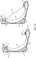
- Figures 1A-10 of the disclosure illustrates aspects of the disclosed exemplary implementations of cooperating tank and sub-rack elements forming a rack superstructure.
- a sub-rack cradle 10 forms a base element of a cooperating rack.
- the sub- rack cradle 10 has substantially vertical first outer wall 11 and a substantially horizontal second outer wall 12.
- the first and second outer walls (11/12) are perpendicular to each other.
- An arc shaped inner wall 13 is disposed within outer walls 11 and 12.
- the inner wall has a top arc end 14 and a bottom arc end 15.
- a structural body frame member 16 is affixed to both the outer walls and the arc shaped inner wall. It is envisioned that the inner wall, outer walls and body frame member are preferably steel. However, those of ordinary skill in the art will recognize that in some instances composite, laminate or other materials with adequate strength may be substituted without departing from the scope of the invention.
- a first tensioner guide 17 Adjacent to the top arc shaped end 14 is a first tensioner guide 17 and adjacent to the bottom arc end 15 is a second tensioner guide 18. A catch 19 is formed in each of the tensioner guides.
- a single tensioner may be used with the opposing end of the system fixed with a fastener such as a pin or a bolt.
- An isolator 25 formed of a rubber-like boundary layer is attached to the arc shaped inner wall 13 to increase friction of a mounted sub-rack tank structure and to cooperate with the expansion and contraction of such a sub-rack tank.
- a top bracket mount 30 extends from the first outer wall and a bottom bracket 32 mount is formed on the second outer wall.
- a front rack leg mounting plate 40 is formed perpendicular to the second outer wall 14.
- One or more back rack leg mountings 42 are formed along the first outer wall 12.
- a cylindrical composite fuel tank 50 with a first end 52 and a second end 54 supports a valve 55 at one end.
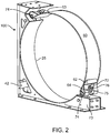
- a strap 60 having a first strap end 62 and a second strap end 63 with a strap mount guide 64 formed in each end is affixed to the sub-rack cradle via a tensioner assembly 70.
- the tensioner assembly having a bolt 72 with a head 73, a plate 74, a spring 75 and a nut 76 used to compress the spring against the plate.
- the strap 60 should be of a metal material and may be stainless steel, plain steel, aluminum, or other metal of sufficient strength to hold a filled fuel tank against the sub-rack cradle against a static force, applied in the six principal directions of eight times the weight of the fully pressurized container with a maximum displacement of 0.50 in.
- the strap 60 may have a rubber or rubber-like isolator disposed between the strap 60 and the tank.
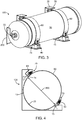
- a fuel tank 50 forms a portion of a frame module 100. Each module also includes the sub-rack cradle 10, tensioners 70 and strap 60. A fuel line 200 is connected to the valve 55 for dispensing gaseous fuels.
- the strength of the module 100 is provided by a combination of cradles and affixed fuel tank 50. Rather than affixed fuel tanks to a ridged frame structure which meets the NFPA 52 and/or other standards disclosed herein is a method and system of sub-rack components and structures that cooperate to form a superstructure.
- the fuel tank forms a sub-member of the rack module thereby reducing weight which in turn can reduce Tare weight of a truck using this system.
- Force line 500 illustrated how the cylindrical fuel tank 50 when affixed to the arc shaped innerwall 13 bridges the unsupported gap 510 between the top arc end 14 and a bottom arc end 15.
- Each fuel tank is cylindrical and preferably has a burst pressure of about 2.2 to 3 times its nominal pressure (psi) rating. That burst pressure equates to a crush strength. Such cylinder can withstand hoop stress and axially stress applied externally of at least a quantity equal to the burst rating. By spanning the gap 510 between top arc end 14 and a bottom arc end 15 the tank 50 cooperates to support the structure along the force line 500.
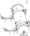
- Each module 100 is mounted to the next. During mounting the next vertical module above the prior one is affixed via top bracket mount 30 of the lower module to bottom bracket 32 mount of the upper module forming a connection 250. The mounting places the substantially horizontal outer wall 12 above and not touching the fuel tank 50 and strap 60 of the below module.
- Figure 6 illustrates the addition of rack legs 300.
- the rack legs form upward support elements of the superstructure forming the rack.
- the modules are connected to the rack legs 300.
- the connections to the rack legs include, at a minimum front connections 310 between the front rack leg mounting plate 40 and a leg 300. Fasteners which may include bolts, pins and the like known in the art are used to connect the superstructure elements.
- the connections to the rack legs also include, at a minimum back connections 320 between the back rack leg mountings 42 front rack leg and a leg 300.
- a third fuel tank 50" is added above the second module 100' and then a strap 60 is affixed with tensioner 70, and the front and back connections (310/320) to legs 300 are completed a third module 100" extending the superstructure while adding a fuel tank is completed.
- the desired fuel tank rack is for three vertical fuel tanks, then the combined three modules as shown in Figures 9-11 form the cooperating rack superstructure with three fuel tanks that also form support elements.
- the foregoing method uses the fuel tanks (50/50'/50”) as a sub-rack members or elements along with the sub-rack cradle to form the rack.
- this arrangement is antithetical to a rigid superstructure rack to which fuel tanks are affixed.
Landscapes
- Engineering & Computer Science (AREA)
- Mechanical Engineering (AREA)
- General Engineering & Computer Science (AREA)
- Life Sciences & Earth Sciences (AREA)
- Sustainable Development (AREA)
- Sustainable Energy (AREA)
- Chemical & Material Sciences (AREA)
- Combustion & Propulsion (AREA)
- Transportation (AREA)
- Cooling, Air Intake And Gas Exhaust, And Fuel Tank Arrangements In Propulsion Units (AREA)
Description
- This disclosure relates to a load bearing compressed gas tank mounting structure for motor vehicles.
- Pressurized cylinder failure is measured in terms of burst pressure. If a cylinder has a 20.7 MPa (3000 psi) rating it will have a burst strength (or failure rating) of 2-3 times that normal 20.7 MPa (3000 psi) rating.
- Pressurized cylinders are useful; for storing and transporting fuels such as hydrogen, natural gas (CNG) and propane.
- Storage of gaseous fuel cylinders/tanks in a tractor or trailer must meet crash safety requirements.
- Tractor Trailers have many different weight ratings which may affect their usage and the cost of usage.
- Gross Vehicle Weight (GVW). This is the total weight of the loaded vehicle. This includes the vehicle itself and the cargo that is loaded on the vehicle.
- Gross Combination Weight (GCW). This is specified by the manufacturer as the maximum loaded weight of a truck/tractor plus the trailer or semi-trailer designed for use with the truck/tractor.
- Gross Vehicle Weight Rating (GVWR). This is the rating that is calculated by the manufacturer as the amount of weight that the vehicle will be when the vehicle itself is weighed, filled with fuel, and loaded according to the manufacturer's specification.
- Gross Combination Weight Rating (GCWR). This is the maximum allowable combined mass of a towing road vehicle, passengers and cargo in the tow vehicle, plus the mass of the trailer and cargo in the trailer. This rating is set by the manufacturer.
- Safety Compliance Weight. The Federal Motor Carrier Safety Regulations (FMCSRs) have two definitions of a Commercial Motor Vehicle (CMV) for interstate carriers; each definition applies to specific safety regulations. Sec. 390.5 defines the weight of a CMV as 4536 kg (10,001 lbs.) or more GVW/GCW or GVWR/GCWR. In this situation, the FMCSA may use either the GVW or the GVWR (whichever is highest). If the actual GVW of the vehicle is 4150 kg (9,150 lbs.) but it has a manufacturers' GVWR of 4763 kg (10,500 lbs.), it is a CMV subject to the rules. The definition in Parts 382 and 383 says a CMV is 11794 or more kgs. (26,001 or more lbs.) GCWR or GVWR. In this case, only the manufacturers' weight rating matters. The actual gross vehicle weight is not a factor in determining compliance. When a state adopts the FMCSRs for their intrastate carriers, a different weight threshold may be adopted for intrastate compliance.
- Registration Weight. The registered weight of a vehicle is not related to any compliance with the FMCSRs. A ve1000hicle must be registered for the actual gross weight or combined gross weight. This means the empty weight of the vehicle plus the empty weight of any towed vehicle, plus the weight of the heaviest load to be carried. Generally, vehicles should not be registered for a weight higher than the weight rating; most states will not allow registration exceeding the weight rating. If the vehicle travels on the highways at a weight higher than the registered weight shown on the registration, a citation may be issued for overweight on vehicle registration.
- Any vehicle operating interstate with a GVW or GCW or registered weight of 11793 kg (26,000 lbs.) or more, or having three axles at any weight, is subject to the International Registration Plan (IRP) for apportioned registration and the International Fuel Tax Agreement (IFTA) for payment of fuel use taxes. These base state agreements do not use the vehicle weight rating when determining compliance.
- Highway Weight. This is the legal weight related to highway size and weight limits. When operating on the interstate system, the maximum permissible weight is 9072 kg (20,000 lbs.) on a single axle, 15422 kg (34,000 lbs.) on a tandem axle, and 36287 kg (80,000 lbs.) max gross weight. The "Bridge Formula" allows motor vehicles to be loaded to the maximum weight only if each group of axles on the vehicle and their spacing also satisfy the requirements of the formula. States must use these limits for their designated or national network highways. While the majority of the states use the federal bridge formula for all roads in their state, some do have a separate state formula for other state or county roads. Tare weight is measured and a truck can be penalized for higher Tare weights.
- National Fire Protection Agency "NFPA" 52: VEHICULAR GASEOUS FUEL SYSTEMS CODE "safeguards people and installations with requirements that mitigate the fire and explosion hazards associated with compressed natural gas (CNG) and liquefied natural gas (LNG) engine fuel systems and fueling facilities."
- Section 6.3.4 of the code specifies that each fuel supply container rack shall be secured to the vehicle body, bed, or frame to prevent damage from road hazards, slippage, loosening, or rotation using a method capable of withstanding a static force in the six principal of eight times the weight of a fully pressurized container(s).
- Moreover section 6.3.5 specifies that each fuel supply container in the rack shall be secured to its cradle in a manner that it is capable of withstanding a static force, applied in the six principal directions of eight times the weight of the fully pressurized container with a maximum displacement of 0.50 in. (13 mm).
- A traditional rack and tank support system provides a steel rack/cage with compartments to hold tanks to meet such safety standards and bear loads.
-
JP 2005 035388 US 5810309 describes a compressed natural gas cylinder mounting assembly for supporting and coupling a compressed natural gas cylinder to the underside of a natural gas vehicle. - Briefly, gaseous fuel stored in cylinders on a tractor and/or trailer add weight. Weight affects cost to operate and regulatory issues.
- Cylindrical pressurized filament wrapped composite cylinders are a light weight alternative to metal tanks for storing gaseous fuels. Such cylinder can withstand hoop stress and axially stress applied externally of at least a quantity equal to the burst rating.
- Traditionally vertical rack for mounting gaseous fuel cylinder are heavy steel or metal racks with trusses supporting the levels. Disclosed herein are aspects of exemplary implementations of a novel tank and rack method and system that obviate the shortfalls of traditional system with a cooperating structure for supporting cylindrical tanks in a vertical configuration with a decrease in at least one of rack footprint, size, mass, complexity and weight.
- Traditionally vertical rack for mounting gaseous fuel cylinder, to meet safety regulations, are heavy steel or metal racks with trusses supporting the levels. Disclosed herein are aspects of exemplary implementations of a novel tank and rack method and system that obviate the shortfalls of traditional system with a cooperating structure for supporting cylindrical tanks in a vertical configuration with a decrease in at least one of rack footprint, size, mass, complexity and weight.
- The present invention provides cooperating rack structures, according to claims 1 to 4, comprising at least two modules, wherein each module comprises a cylindrical composite fuel tank with a first end and a second end supporting a valve, a first sub-rack cradle disposed at the first end, a second sub-rack cradle disposed at the second end, wherein each sub-rack cradle comprises a substantially vertical first outer wall, a substantially horizontal second outer wall, an arc shaped inner wall having a top arc end and a bottom arc end, a structural body frame member affixed to the first and second outer walls and the arc shaped inner wall, a first tensioner guide adjacent to the top arc shaped end, a second tensioner guide adjacent to the bottom arc end, a catch formed in each of the tensioner guides, a top bracket mount extending from the first outer wall, a bottom bracket mount formed on the second outer wall, a front rack leg mounting plate formed perpendicular to the second outer wall, and one or more back rack leg mountings formed along the first outer wall, each module further comprising one or more tensioner assemblies, and two straps, each strap attached to each of the first and second sub-rack cradles and wrapping around the cylindrical body of the fuel tank, each strap having a first strap end and a second strap end with a strap mount guide formed in each end, wherein each strap is affixed to the sub-rack cradle via one or more of the tensioner assemblies, with the tensioner assembly having a bolt with a head, a plate, a spring, and a nut used to compress the spring against the plate, and wherein the at least two modules are mounted together in a vertically stacked arrangement, with each successive upper module above the prior lower module being affixed via top bracket mount of the lower module to bottom bracket mount of the upper module forming a connection, and wherein the mounting places the substantially horizontal outer walls of the sub-rack cradles of the upper module above and not touching the fuel tank and straps of the lower module.
- The present invention provides a method, according to claim 5, of reducing the weight of vertical storage of fuel tanks of the above described cooperating rack structure for use in motor vehicles.
- The general description and the following detailed description are exemplary and explanatory only and are not restrictive of the invention, as defined in the appended claims. Other aspects of the present invention will be apparent to those skilled in the art in view of the detailed description of the disclosure as provided herein.
- The above-mentioned features of the present invention will become more apparent with reference to the following description taken in conjunction with the accompanying drawings wherein like reference numerals denote like elements and in which:
-
Figure 1A shows aspects of sub-rack cradles; -
Figure 1B shows aspects of a fuel tank which is a sub-rack member support member; -
Figure 2 shows aspects of a sub-rack strap on a sub-rack cradle; -
Figures 3 and 4 show aspects of a first sub-rack module; -
Figure 5 shows aspects of an assembly of a rack; -
Figure 6 shows aspects of an assembly of a rack; -
Figure 7 shows aspects of an assembly of a rack; -
Figure 8 shows aspects of an assembly of a rack; and, -
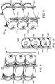
Figures 9-11 show aspects of an assembled rack. - As shall be appreciated by those having ordinary skill in the art, the figures are not to scale and modifications to scale within a figure or across the figures are considered within the present disclosure.
- Unlike traditional rack and tank support system with a steel rack/cage with compartments to hold tanks. Wherein the rack is a unitary structure to which tanks are secured and the tanks form no part of the superstructure, disclosed herein are aspects of exemplary systems and methods wherein a cylindrical pressurized tank form an integral part of a superstructure for supporting one or more of such tanks in a motor vehicle.
-
Figures 1A-10 of the disclosure illustrates aspects of the disclosed exemplary implementations of cooperating tank and sub-rack elements forming a rack superstructure. - A
sub-rack cradle 10 forms a base element of a cooperating rack. The sub-rack cradle 10 has substantially vertical firstouter wall 11 and a substantially horizontal secondouter wall 12. The first and second outer walls (11/12) are perpendicular to each other. An arc shapedinner wall 13 is disposed withinouter walls top arc end 14 and abottom arc end 15. A structuralbody frame member 16 is affixed to both the outer walls and the arc shaped inner wall. It is envisioned that the inner wall, outer walls and body frame member are preferably steel. However, those of ordinary skill in the art will recognize that in some instances composite, laminate or other materials with adequate strength may be substituted without departing from the scope of the invention. - Adjacent to the top arc shaped
end 14 is afirst tensioner guide 17 and adjacent to thebottom arc end 15 is asecond tensioner guide 18. Acatch 19 is formed in each of the tensioner guides. In some implementations, a single tensioner may be used with the opposing end of the system fixed with a fastener such as a pin or a bolt. - An isolator 25 formed of a rubber-like boundary layer is attached to the arc shaped
inner wall 13 to increase friction of a mounted sub-rack tank structure and to cooperate with the expansion and contraction of such a sub-rack tank. - A
top bracket mount 30 extends from the first outer wall and abottom bracket 32 mount is formed on the second outer wall. A front rackleg mounting plate 40 is formed perpendicular to the secondouter wall 14. One or more backrack leg mountings 42 are formed along the firstouter wall 12. - A cylindrical
composite fuel tank 50 with afirst end 52 and asecond end 54 supports avalve 55 at one end. Astrap 60 having afirst strap end 62 and asecond strap end 63 with astrap mount guide 64 formed in each end is affixed to the sub-rack cradle via atensioner assembly 70. The tensioner assembly having abolt 72 with ahead 73, aplate 74, aspring 75 and anut 76 used to compress the spring against the plate. Thestrap 60 should be of a metal material and may be stainless steel, plain steel, aluminum, or other metal of sufficient strength to hold a filled fuel tank against the sub-rack cradle against a static force, applied in the six principal directions of eight times the weight of the fully pressurized container with a maximum displacement of 0.50 in. Thestrap 60 may have a rubber or rubber-like isolator disposed between thestrap 60 and the tank. - A
fuel tank 50 forms a portion of aframe module 100. Each module also includes thesub-rack cradle 10,tensioners 70 andstrap 60. Afuel line 200 is connected to thevalve 55 for dispensing gaseous fuels. - The strength of the
module 100 is provided by a combination of cradles and affixedfuel tank 50. Rather than affixed fuel tanks to a ridged frame structure which meets theNFPA 52 and/or other standards disclosed herein is a method and system of sub-rack components and structures that cooperate to form a superstructure. The fuel tank forms a sub-member of the rack module thereby reducing weight which in turn can reduce Tare weight of a truck using this system. -
Force line 500 illustrated how thecylindrical fuel tank 50 when affixed to the arc shaped innerwall 13 bridges theunsupported gap 510 between thetop arc end 14 and abottom arc end 15. When the next module(s) is added vertically above the first module (Figures 5-11 ) absent the cooperating tank structure the rack structure would not have sufficient strength to hold the next level(s) above filled fuel tanks against the sub- rack cradle against a static force, applied in the six principal directions of eight times the weight of the fully pressurized container with a maximum displacement of 0.50 in. - Each fuel tank is cylindrical and preferably has a burst pressure of about 2.2 to 3 times its nominal pressure (psi) rating. That burst pressure equates to a crush strength. Such cylinder can withstand hoop stress and axially stress applied externally of at least a quantity equal to the burst rating. By spanning the
gap 510 betweentop arc end 14 and abottom arc end 15 thetank 50 cooperates to support the structure along theforce line 500. - Each
module 100 is mounted to the next. During mounting the next vertical module above the prior one is affixed viatop bracket mount 30 of the lower module tobottom bracket 32 mount of the upper module forming aconnection 250. The mounting places the substantially horizontalouter wall 12 above and not touching thefuel tank 50 andstrap 60 of the below module. -
Figure 6 illustrates the addition ofrack legs 300. The rack legs form upward support elements of the superstructure forming the rack. The modules are connected to therack legs 300. The connections to the rack legs include, at a minimumfront connections 310 between the front rackleg mounting plate 40 and aleg 300. Fasteners which may include bolts, pins and the like known in the art are used to connect the superstructure elements. The connections to the rack legs also include, at aminimum back connections 320 between the backrack leg mountings 42 front rack leg and aleg 300. - When a second fuel tank 50' is added above the
first module 100 and then astrap 60 is affixed withtensioner 70, and the front and back connections (310/320) tolegs 300 are completed asecond module 100' extending the superstructure while adding a fuel tank is completed. The foregoing method uses the fuel tanks (50/50') as a sub-rack members or elements along with the sub-rack cradle to form the rack. Those of ordinary skill in the art will recognize that this arrangement is antithetical to a rigid superstructure rack to which fuel tanks are affixed. - When a
third fuel tank 50" is added above thesecond module 100' and then astrap 60 is affixed withtensioner 70, and the front and back connections (310/320) tolegs 300 are completed athird module 100" extending the superstructure while adding a fuel tank is completed. If the desired fuel tank rack is for three vertical fuel tanks, then the combined three modules as shown inFigures 9-11 form the cooperating rack superstructure with three fuel tanks that also form support elements. The foregoing method uses the fuel tanks (50/50'/50") as a sub-rack members or elements along with the sub-rack cradle to form the rack. Those of ordinary skill in the art will recognize that this arrangement is antithetical to a rigid superstructure rack to which fuel tanks are affixed.
Claims (5)
- A cooperating rack structure comprising at least two modules (100/100'),
wherein each module (100/100') comprises:a cylindrical composite fuel tank (50) with a first end (52) and a second end (54) supporting a valve (55);a first sub-rack cradle (10) disposed at the first end;a second sub-rack cradle (10) disposed at the second end;wherein each sub-rack cradle comprises a substantially vertical first outer wall (11), a substantially horizontal second outer wall (12), an arc shaped inner wall (13) having a top arc end (14) and a bottom arc end (15), a structural body frame member (16) affixed to the first and second outer walls and the arc shaped inner wall, a first tensioner guide (17) adjacent to the top arc shaped end (14), a second tensioner guide (18) adjacent to the bottom arc end (15), a catch (19) formed in each of the tensioner guides, a top bracket mount (30) extending from the first outer wall, a bottom bracket mount (32) formed on the second outer wall, a front rack leg mounting plate (40) formed perpendicular to the second outer wall (14), and one or more back rack leg mountings (42) formed along the first outer wall (12);one or more tensioner assemblies (70); andtwo straps (60), each strap attached to each of the first and second sub-rack cradles and wrapping around the cylindrical body of the fuel tank (50), each strap having a first strap end (62) and a second strap end (63) with a strap mount guide (64) formed in each end,wherein each strap (60) is affixed to the sub-rack cradle (10) via one or more of the tensioner assemblies (70), with the tensioner assembly (70) having a bolt (72) with a head (73), a plate (74), a spring (75) and a nut (76) used to compress the spring against the plate; andwherein the at least two modules are mounted together in a vertically stacked arrangement, with each successive upper module (100') above the prior lower module (100) being affixed via top bracket mount (30) of the lower module to bottom bracket mount (32) of the upper module forming a connection (250), and wherein the mounting places the substantially horizontal outer walls (12) of the sub-rack cradles of the upper module (100') above and not touching the fuel tank (50) and straps (60) of the lower module (100). - The cooperating rack structure of claim 1 wherein the modules are affixed to legs (300) with connections between the legs (300) and front rack leg mounting plate (40) and back rack leg mounting (42).
- The cooperating rack structure of claim 1 wherein the fuel tanks (50/50'/50") in each module form a portion of the superstructure of the rack (400).
- The cooperating rack structure of claim 1 wherein an isolator (25) formed of a rubber-like boundary layer is attached to the arc shaped inner wall (13) and each strap (60) further comprises a rubber or rubber-like isolator disposed between the strap (60) and the fuel tank.
- A method of reduced weight vertical storage of fuel tanks of the cooperating rack structure of claim 1 for use in motor vehicles, the method comprising:affixing a cylindrical fuel tank (50) to an arch shaped inner wall (13) of a sub-rack cradle (10);strapping (60) the fuel tank against the sub-rack cradle whereby the fuel tank spans a gap (510) between ends (14/15) of the arch shaped inner wall and acts as a load bearing support; and,wherein the weight of the rack compared to a rigid frame rack holding the same cylinders is reduced.
Applications Claiming Priority (2)
| Application Number | Priority Date | Filing Date | Title |
|---|---|---|---|
| US201461993981P | 2014-05-15 | 2014-05-15 | |
| PCT/US2015/030904 WO2015175842A1 (en) | 2014-05-15 | 2015-05-14 | Cooperating tank and rack superstructure |
Publications (3)
| Publication Number | Publication Date |
|---|---|
| EP3142888A1 EP3142888A1 (en) | 2017-03-22 |
| EP3142888A4 EP3142888A4 (en) | 2018-01-10 |
| EP3142888B1 true EP3142888B1 (en) | 2021-03-03 |
Family
ID=54480716
Family Applications (1)
| Application Number | Title | Priority Date | Filing Date |
|---|---|---|---|
| EP15792934.0A Active EP3142888B1 (en) | 2014-05-15 | 2015-05-14 | Cooperating tank and rack superstructure |
Country Status (4)
| Country | Link |
|---|---|
| US (1) | US10696154B2 (en) |
| EP (1) | EP3142888B1 (en) |
| CA (2) | CA3134244C (en) |
| WO (1) | WO2015175842A1 (en) |
Families Citing this family (31)
| Publication number | Priority date | Publication date | Assignee | Title |
|---|---|---|---|---|
| US20140175782A1 (en) | 2012-10-19 | 2014-06-26 | Agility Fuel Systems, Inc. | Systems and methods for mounting a fuel system |
| DE102015206826A1 (en) * | 2015-03-17 | 2016-09-22 | Bayerische Motoren Werke Aktiengesellschaft | Pressure vessel for a motor vehicle |
| USD849662S1 (en) | 2016-05-21 | 2019-05-28 | Worthington Industries, Inc. | Cylinder support system |
| USD816010S1 (en) | 2016-05-21 | 2018-04-24 | Worthington Industries, Inc. | Cylinder support system |
| CA3024866A1 (en) | 2016-05-21 | 2017-11-30 | Worthington Industries, Inc. | Methods and systems for alternative fuel container support |
| USD858740S1 (en) * | 2017-05-22 | 2019-09-03 | Worthington Industries, Inc. | Plate for tank support system |
| PE20220107A1 (en) | 2019-03-22 | 2022-01-26 | Agility Fuel Systems Llc | VEHICLE FRAME RAIL MOUNTABLE FUEL SYSTEM |
| US11440399B2 (en) | 2019-03-22 | 2022-09-13 | Agility Fuel Systems Llc | Fuel system mountable to a vehicle frame |
| USD900592S1 (en) * | 2019-04-29 | 2020-11-03 | Hfe International | Mounting bracket |
| US20200347992A1 (en) | 2019-05-02 | 2020-11-05 | Agility Fuel Systems Llc | Polymeric liner based gas cylinder with reduced permeability |
| KR102882428B1 (en) * | 2020-09-15 | 2025-11-06 | 현대자동차주식회사 | Apparatus for fixating pressure vessel |
| DE102020211813A1 (en) | 2020-09-22 | 2022-03-24 | Volkswagen Aktiengesellschaft | Expandable pressure tank system for a motor vehicle |
| WO2022094483A1 (en) * | 2020-11-02 | 2022-05-05 | Hyzon Motors Inc. | Frame assembly for transporting vessels and vehicle including the same |
| US12005773B2 (en) * | 2021-07-28 | 2024-06-11 | Ford Global Technologies, Llc | Vehicle tank mounting assembly |
| US12048377B2 (en) | 2021-11-23 | 2024-07-30 | Adrian Steel Company | Tank rack |
| JP7432646B2 (en) * | 2022-03-31 | 2024-02-16 | 株式会社三井E&S | Tank and tank structure and manufacturing method thereof |
| JP7753983B2 (en) * | 2022-06-01 | 2025-10-15 | トヨタ自動車株式会社 | Tank mounting structure |
| CN115320370A (en) * | 2022-07-11 | 2022-11-11 | 东风汽车集团股份有限公司 | Fixing device, hydrogen storage module and vehicle |
| JP2024031513A (en) * | 2022-08-26 | 2024-03-07 | トヨタ自動車株式会社 | cardle |
| DE102022129587A1 (en) | 2022-11-09 | 2024-05-16 | Bayerische Motoren Werke Aktiengesellschaft | Mounting device for holding tank bottles |
| USD997696S1 (en) * | 2022-11-15 | 2023-09-05 | Zijiang Yang | Horizontal wall mount rack |
| DE102023101159A1 (en) * | 2023-01-18 | 2024-07-18 | Friedrich Boysen GmbH & Co KG. | Tank system |
| US20240271761A1 (en) * | 2023-02-07 | 2024-08-15 | Hyzon Motors USA Inc. | Modular hydrogen storage system |
| EP4450400A1 (en) * | 2023-04-17 | 2024-10-23 | Airbus Operations, S.L.U. | An aircraft section |
| US20240359554A1 (en) * | 2023-04-27 | 2024-10-31 | Faurecia Emissions Control Technologies, Usa, Llc | Tank mount system |
| DE102023111829A1 (en) | 2023-05-05 | 2024-11-07 | Daimler Truck AG | Device for accommodating at least one gas tank in a commercial vehicle |
| USD1104204S1 (en) * | 2023-06-02 | 2025-12-02 | Davy Gas Inc. | High pressure gas storage unit |
| KR102771976B1 (en) * | 2023-06-28 | 2025-02-26 | 일진하이솔루스 주식회사 | Apparatus for fixating hydrogen tank |
| KR20250010955A (en) * | 2023-07-13 | 2025-01-21 | 현대자동차주식회사 | Apparatus for suportting pressure vessel |
| DE102024118126A1 (en) * | 2024-06-26 | 2025-12-31 | Friedrich Boysen Gmbh & Co. Kg | Tank module and modular vehicle tank system |
| CN118959872A (en) * | 2024-09-03 | 2024-11-15 | 一汽解放汽车有限公司 | Gas tank strap fastening device and vehicle |
Family Cites Families (11)
| Publication number | Priority date | Publication date | Assignee | Title |
|---|---|---|---|---|
| US5810309A (en) * | 1996-12-26 | 1998-09-22 | New York State Electric & Gas Corporation | Natural gas cylinder mounting assembly for a natural gas vehicle, and the method of installation |
| FR2813235B1 (en) * | 2000-08-30 | 2002-10-25 | Commissariat Energie Atomique | THERMOPLASTIC STRUCTURE AND RESERVOIR |
| GB0112169D0 (en) * | 2001-05-18 | 2001-07-11 | Maltab Ltd | Apparatus |
| JP2005035388A (en) | 2003-07-14 | 2005-02-10 | Mitsubishi Fuso Truck & Bus Corp | Tank mounting structure |
| US7624753B2 (en) * | 2004-08-10 | 2009-12-01 | Gm Global Technology Operations, Inc. | Container for gas storage tanks in a vehicle |
| JP4778737B2 (en) * | 2005-07-05 | 2011-09-21 | 昭和電工株式会社 | Pressure vessel |
| JP4349457B2 (en) * | 2007-10-23 | 2009-10-21 | トヨタ自動車株式会社 | High-pressure tank mounted vehicle and tank assembly |
| US8534403B2 (en) * | 2008-09-26 | 2013-09-17 | Ford Global Technologies, Llc | CNG-fueled vehicle with fuel tanks packaged between cab and bed |
| US8915682B2 (en) * | 2009-10-05 | 2014-12-23 | Surayut Posirisuk | Jigs and fixtures of CNG containers for motor vehicles |
| CN202413403U (en) * | 2012-02-03 | 2012-09-05 | 中国重汽集团济南动力有限公司 | Rear-mounted type LNG (liquefied natural gas) gas-cylinder fixing device |
| DE102012004319A1 (en) * | 2012-03-03 | 2013-09-05 | Volkswagen Aktiengesellschaft | Device for fastening of tension strap of gas tank used in vehicle, has plate spring and tension strap that are operatively connected, and includes one fastening element that is arranged on rod in accordance with one of the bolts |
-
2015
- 2015-05-14 CA CA3134244A patent/CA3134244C/en active Active
- 2015-05-14 CA CA2949158A patent/CA2949158A1/en not_active Abandoned
- 2015-05-14 WO PCT/US2015/030904 patent/WO2015175842A1/en not_active Ceased
- 2015-05-14 EP EP15792934.0A patent/EP3142888B1/en active Active
-
2016
- 2016-11-11 US US15/349,786 patent/US10696154B2/en active Active
Non-Patent Citations (1)
| Title |
|---|
| None * |
Also Published As
| Publication number | Publication date |
|---|---|
| US10696154B2 (en) | 2020-06-30 |
| WO2015175842A1 (en) | 2015-11-19 |
| EP3142888A1 (en) | 2017-03-22 |
| US20170057348A1 (en) | 2017-03-02 |
| CA2949158A1 (en) | 2015-11-19 |
| EP3142888A4 (en) | 2018-01-10 |
| CA3134244C (en) | 2024-02-20 |
| CA3134244A1 (en) | 2015-11-19 |
Similar Documents
| Publication | Publication Date | Title |
|---|---|---|
| US10696154B2 (en) | Cooperating tank and rack superstructure | |
| CA2949161C (en) | Tanks forming rack superstructure | |
| US10518690B2 (en) | Intermodal tank transport system, components, and methods | |
| US8146761B2 (en) | Intermodal container for transporting natural gas | |
| US20160363266A1 (en) | Modular fuel storage system | |
| CA2809250C (en) | Tank support apparatus and method | |
| AU2022314177A1 (en) | Holding frame for fastening high-pressure storage tanks to vehicles, more particularly a utility vehicle, and vehicle having the holding frame | |
| US20080067178A1 (en) | Portable tank and tank container for liquefied gas transportation | |
| US11713848B2 (en) | Support structure for cryogenic transport trailer | |
| EP2057444A2 (en) | Method of measuring the weight of bulk liquid material within a trailer | |
| WO2008081401A1 (en) | A transport and distribution vehicle for compressed natural gas tubes | |
| US20240271761A1 (en) | Modular hydrogen storage system | |
| US20240310001A1 (en) | Modular pressure vessel mounting apparatus | |
| RU2624781C1 (en) | Mobile system of compressed gas supply | |
| CN216886258U (en) | Vehicle with a steering wheel | |
| EP3792110B1 (en) | Support structure and related fixing system of pallets or pallet-based baskets | |
| RU2397080C2 (en) | Device to fasten containers on platform | |
| Cohen et al. | Hydrogen delivery and storage options for backup power and off-grid primary power fuel cell systems | |
| WO2024196347A1 (en) | Modular pressure vessel mounting apparatus |
Legal Events
| Date | Code | Title | Description |
|---|---|---|---|
| STAA | Information on the status of an ep patent application or granted ep patent |
Free format text: STATUS: THE INTERNATIONAL PUBLICATION HAS BEEN MADE |
|
| PUAI | Public reference made under article 153(3) epc to a published international application that has entered the european phase |
Free format text: ORIGINAL CODE: 0009012 |
|
| STAA | Information on the status of an ep patent application or granted ep patent |
Free format text: STATUS: REQUEST FOR EXAMINATION WAS MADE |
|
| 17P | Request for examination filed |
Effective date: 20161209 |
|
| AK | Designated contracting states |
Kind code of ref document: A1 Designated state(s): AL AT BE BG CH CY CZ DE DK EE ES FI FR GB GR HR HU IE IS IT LI LT LU LV MC MK MT NL NO PL PT RO RS SE SI SK SM TR |
|
| AX | Request for extension of the european patent |
Extension state: BA ME |
|
| DAV | Request for validation of the european patent (deleted) | ||
| DAX | Request for extension of the european patent (deleted) | ||
| RIC1 | Information provided on ipc code assigned before grant |
Ipc: B60K 15/067 20060101ALI20171130BHEP Ipc: B60K 15/07 20060101AFI20171130BHEP Ipc: B60K 15/03 20060101ALI20171130BHEP Ipc: F17C 13/08 20060101ALI20171130BHEP |
|
| A4 | Supplementary search report drawn up and despatched |
Effective date: 20171208 |
|
| STAA | Information on the status of an ep patent application or granted ep patent |
Free format text: STATUS: EXAMINATION IS IN PROGRESS |
|
| 17Q | First examination report despatched |
Effective date: 20190716 |
|
| GRAP | Despatch of communication of intention to grant a patent |
Free format text: ORIGINAL CODE: EPIDOSNIGR1 |
|
| STAA | Information on the status of an ep patent application or granted ep patent |
Free format text: STATUS: GRANT OF PATENT IS INTENDED |
|
| INTG | Intention to grant announced |
Effective date: 20200909 |
|
| GRAS | Grant fee paid |
Free format text: ORIGINAL CODE: EPIDOSNIGR3 |
|
| GRAA | (expected) grant |
Free format text: ORIGINAL CODE: 0009210 |
|
| STAA | Information on the status of an ep patent application or granted ep patent |
Free format text: STATUS: THE PATENT HAS BEEN GRANTED |
|
| AK | Designated contracting states |
Kind code of ref document: B1 Designated state(s): AL AT BE BG CH CY CZ DE DK EE ES FI FR GB GR HR HU IE IS IT LI LT LU LV MC MK MT NL NO PL PT RO RS SE SI SK SM TR |
|
| RAP1 | Party data changed (applicant data changed or rights of an application transferred) |
Owner name: QUANTUM FUEL SYSTEMS LLC |
|
| REG | Reference to a national code |
Ref country code: GB Ref legal event code: FG4D |
|
| RIN1 | Information on inventor provided before grant (corrected) |
Inventor name: KIM, TAE Inventor name: JAEGER, CHRISTOPHER Inventor name: AROLD, MARK Inventor name: HUDAK, JOSEPH Inventor name: OLISCHEFSKI, DERRIN |
|
| REG | Reference to a national code |
Ref country code: CH Ref legal event code: EP Ref country code: AT Ref legal event code: REF Ref document number: 1366833 Country of ref document: AT Kind code of ref document: T Effective date: 20210315 |
|
| REG | Reference to a national code |
Ref country code: DE Ref legal event code: R096 Ref document number: 602015066372 Country of ref document: DE |
|
| REG | Reference to a national code |
Ref country code: IE Ref legal event code: FG4D |
|
| REG | Reference to a national code |
Ref country code: NL Ref legal event code: FP |
|
| REG | Reference to a national code |
Ref country code: LT Ref legal event code: MG9D |
|
| PG25 | Lapsed in a contracting state [announced via postgrant information from national office to epo] |
Ref country code: LT Free format text: LAPSE BECAUSE OF FAILURE TO SUBMIT A TRANSLATION OF THE DESCRIPTION OR TO PAY THE FEE WITHIN THE PRESCRIBED TIME-LIMIT Effective date: 20210303 Ref country code: NO Free format text: LAPSE BECAUSE OF FAILURE TO SUBMIT A TRANSLATION OF THE DESCRIPTION OR TO PAY THE FEE WITHIN THE PRESCRIBED TIME-LIMIT Effective date: 20210603 Ref country code: GR Free format text: LAPSE BECAUSE OF FAILURE TO SUBMIT A TRANSLATION OF THE DESCRIPTION OR TO PAY THE FEE WITHIN THE PRESCRIBED TIME-LIMIT Effective date: 20210604 Ref country code: FI Free format text: LAPSE BECAUSE OF FAILURE TO SUBMIT A TRANSLATION OF THE DESCRIPTION OR TO PAY THE FEE WITHIN THE PRESCRIBED TIME-LIMIT Effective date: 20210303 Ref country code: HR Free format text: LAPSE BECAUSE OF FAILURE TO SUBMIT A TRANSLATION OF THE DESCRIPTION OR TO PAY THE FEE WITHIN THE PRESCRIBED TIME-LIMIT Effective date: 20210303 Ref country code: BG Free format text: LAPSE BECAUSE OF FAILURE TO SUBMIT A TRANSLATION OF THE DESCRIPTION OR TO PAY THE FEE WITHIN THE PRESCRIBED TIME-LIMIT Effective date: 20210603 |
|
| REG | Reference to a national code |
Ref country code: AT Ref legal event code: MK05 Ref document number: 1366833 Country of ref document: AT Kind code of ref document: T Effective date: 20210303 |
|
| PG25 | Lapsed in a contracting state [announced via postgrant information from national office to epo] |
Ref country code: SE Free format text: LAPSE BECAUSE OF FAILURE TO SUBMIT A TRANSLATION OF THE DESCRIPTION OR TO PAY THE FEE WITHIN THE PRESCRIBED TIME-LIMIT Effective date: 20210303 Ref country code: RS Free format text: LAPSE BECAUSE OF FAILURE TO SUBMIT A TRANSLATION OF THE DESCRIPTION OR TO PAY THE FEE WITHIN THE PRESCRIBED TIME-LIMIT Effective date: 20210303 Ref country code: LV Free format text: LAPSE BECAUSE OF FAILURE TO SUBMIT A TRANSLATION OF THE DESCRIPTION OR TO PAY THE FEE WITHIN THE PRESCRIBED TIME-LIMIT Effective date: 20210303 Ref country code: PL Free format text: LAPSE BECAUSE OF FAILURE TO SUBMIT A TRANSLATION OF THE DESCRIPTION OR TO PAY THE FEE WITHIN THE PRESCRIBED TIME-LIMIT Effective date: 20210303 |
|
| PG25 | Lapsed in a contracting state [announced via postgrant information from national office to epo] |
Ref country code: SM Free format text: LAPSE BECAUSE OF FAILURE TO SUBMIT A TRANSLATION OF THE DESCRIPTION OR TO PAY THE FEE WITHIN THE PRESCRIBED TIME-LIMIT Effective date: 20210303 Ref country code: AT Free format text: LAPSE BECAUSE OF FAILURE TO SUBMIT A TRANSLATION OF THE DESCRIPTION OR TO PAY THE FEE WITHIN THE PRESCRIBED TIME-LIMIT Effective date: 20210303 Ref country code: CZ Free format text: LAPSE BECAUSE OF FAILURE TO SUBMIT A TRANSLATION OF THE DESCRIPTION OR TO PAY THE FEE WITHIN THE PRESCRIBED TIME-LIMIT Effective date: 20210303 Ref country code: EE Free format text: LAPSE BECAUSE OF FAILURE TO SUBMIT A TRANSLATION OF THE DESCRIPTION OR TO PAY THE FEE WITHIN THE PRESCRIBED TIME-LIMIT Effective date: 20210303 |
|
| PG25 | Lapsed in a contracting state [announced via postgrant information from national office to epo] |
Ref country code: IS Free format text: LAPSE BECAUSE OF FAILURE TO SUBMIT A TRANSLATION OF THE DESCRIPTION OR TO PAY THE FEE WITHIN THE PRESCRIBED TIME-LIMIT Effective date: 20210703 Ref country code: SK Free format text: LAPSE BECAUSE OF FAILURE TO SUBMIT A TRANSLATION OF THE DESCRIPTION OR TO PAY THE FEE WITHIN THE PRESCRIBED TIME-LIMIT Effective date: 20210303 Ref country code: RO Free format text: LAPSE BECAUSE OF FAILURE TO SUBMIT A TRANSLATION OF THE DESCRIPTION OR TO PAY THE FEE WITHIN THE PRESCRIBED TIME-LIMIT Effective date: 20210303 Ref country code: PT Free format text: LAPSE BECAUSE OF FAILURE TO SUBMIT A TRANSLATION OF THE DESCRIPTION OR TO PAY THE FEE WITHIN THE PRESCRIBED TIME-LIMIT Effective date: 20210705 Ref country code: ES Free format text: LAPSE BECAUSE OF FAILURE TO SUBMIT A TRANSLATION OF THE DESCRIPTION OR TO PAY THE FEE WITHIN THE PRESCRIBED TIME-LIMIT Effective date: 20210303 |
|
| REG | Reference to a national code |
Ref country code: DE Ref legal event code: R097 Ref document number: 602015066372 Country of ref document: DE |
|
| REG | Reference to a national code |
Ref country code: CH Ref legal event code: PL |
|
| PLBE | No opposition filed within time limit |
Free format text: ORIGINAL CODE: 0009261 |
|
| STAA | Information on the status of an ep patent application or granted ep patent |
Free format text: STATUS: NO OPPOSITION FILED WITHIN TIME LIMIT |
|
| PG25 | Lapsed in a contracting state [announced via postgrant information from national office to epo] |
Ref country code: DK Free format text: LAPSE BECAUSE OF FAILURE TO SUBMIT A TRANSLATION OF THE DESCRIPTION OR TO PAY THE FEE WITHIN THE PRESCRIBED TIME-LIMIT Effective date: 20210303 Ref country code: MC Free format text: LAPSE BECAUSE OF FAILURE TO SUBMIT A TRANSLATION OF THE DESCRIPTION OR TO PAY THE FEE WITHIN THE PRESCRIBED TIME-LIMIT Effective date: 20210303 Ref country code: LI Free format text: LAPSE BECAUSE OF NON-PAYMENT OF DUE FEES Effective date: 20210531 Ref country code: LU Free format text: LAPSE BECAUSE OF NON-PAYMENT OF DUE FEES Effective date: 20210514 Ref country code: CH Free format text: LAPSE BECAUSE OF NON-PAYMENT OF DUE FEES Effective date: 20210531 Ref country code: AL Free format text: LAPSE BECAUSE OF FAILURE TO SUBMIT A TRANSLATION OF THE DESCRIPTION OR TO PAY THE FEE WITHIN THE PRESCRIBED TIME-LIMIT Effective date: 20210303 |
|
| 26N | No opposition filed |
Effective date: 20211206 |
|
| REG | Reference to a national code |
Ref country code: BE Ref legal event code: MM Effective date: 20210531 |
|
| PG25 | Lapsed in a contracting state [announced via postgrant information from national office to epo] |
Ref country code: SI Free format text: LAPSE BECAUSE OF FAILURE TO SUBMIT A TRANSLATION OF THE DESCRIPTION OR TO PAY THE FEE WITHIN THE PRESCRIBED TIME-LIMIT Effective date: 20210303 |
|
| PG25 | Lapsed in a contracting state [announced via postgrant information from national office to epo] |
Ref country code: IT Free format text: LAPSE BECAUSE OF FAILURE TO SUBMIT A TRANSLATION OF THE DESCRIPTION OR TO PAY THE FEE WITHIN THE PRESCRIBED TIME-LIMIT Effective date: 20210303 Ref country code: IE Free format text: LAPSE BECAUSE OF NON-PAYMENT OF DUE FEES Effective date: 20210514 |
|
| PG25 | Lapsed in a contracting state [announced via postgrant information from national office to epo] |
Ref country code: IS Free format text: LAPSE BECAUSE OF FAILURE TO SUBMIT A TRANSLATION OF THE DESCRIPTION OR TO PAY THE FEE WITHIN THE PRESCRIBED TIME-LIMIT Effective date: 20210703 |
|
| PG25 | Lapsed in a contracting state [announced via postgrant information from national office to epo] |
Ref country code: BE Free format text: LAPSE BECAUSE OF NON-PAYMENT OF DUE FEES Effective date: 20210531 |
|
| PG25 | Lapsed in a contracting state [announced via postgrant information from national office to epo] |
Ref country code: HU Free format text: LAPSE BECAUSE OF FAILURE TO SUBMIT A TRANSLATION OF THE DESCRIPTION OR TO PAY THE FEE WITHIN THE PRESCRIBED TIME-LIMIT; INVALID AB INITIO Effective date: 20150514 |
|
| PG25 | Lapsed in a contracting state [announced via postgrant information from national office to epo] |
Ref country code: CY Free format text: LAPSE BECAUSE OF FAILURE TO SUBMIT A TRANSLATION OF THE DESCRIPTION OR TO PAY THE FEE WITHIN THE PRESCRIBED TIME-LIMIT Effective date: 20210303 |
|
| PG25 | Lapsed in a contracting state [announced via postgrant information from national office to epo] |
Ref country code: MK Free format text: LAPSE BECAUSE OF FAILURE TO SUBMIT A TRANSLATION OF THE DESCRIPTION OR TO PAY THE FEE WITHIN THE PRESCRIBED TIME-LIMIT Effective date: 20210303 |
|
| PG25 | Lapsed in a contracting state [announced via postgrant information from national office to epo] |
Ref country code: TR Free format text: LAPSE BECAUSE OF FAILURE TO SUBMIT A TRANSLATION OF THE DESCRIPTION OR TO PAY THE FEE WITHIN THE PRESCRIBED TIME-LIMIT Effective date: 20210303 |
|
| PG25 | Lapsed in a contracting state [announced via postgrant information from national office to epo] |
Ref country code: MT Free format text: LAPSE BECAUSE OF FAILURE TO SUBMIT A TRANSLATION OF THE DESCRIPTION OR TO PAY THE FEE WITHIN THE PRESCRIBED TIME-LIMIT Effective date: 20210303 |
|
| PGFP | Annual fee paid to national office [announced via postgrant information from national office to epo] |
Ref country code: DE Payment date: 20250529 Year of fee payment: 11 |
|
| PGFP | Annual fee paid to national office [announced via postgrant information from national office to epo] |
Ref country code: GB Payment date: 20260312 Year of fee payment: 12 |
|
| PGFP | Annual fee paid to national office [announced via postgrant information from national office to epo] |
Ref country code: NL Payment date: 20260317 Year of fee payment: 12 |
|
| PGFP | Annual fee paid to national office [announced via postgrant information from national office to epo] |
Ref country code: FR Payment date: 20260309 Year of fee payment: 12 |