EP3142872B1 - Device for automatic inflation-deflation of a containment capacity for a pressurised gaseous fluid - Google Patents
Device for automatic inflation-deflation of a containment capacity for a pressurised gaseous fluid Download PDFInfo
- Publication number
- EP3142872B1 EP3142872B1 EP15725826.0A EP15725826A EP3142872B1 EP 3142872 B1 EP3142872 B1 EP 3142872B1 EP 15725826 A EP15725826 A EP 15725826A EP 3142872 B1 EP3142872 B1 EP 3142872B1
- Authority
- EP
- European Patent Office
- Prior art keywords
- washer
- deflation
- inflation
- gaseous fluid
- orifice
- Prior art date
- Legal status (The legal status is an assumption and is not a legal conclusion. Google has not performed a legal analysis and makes no representation as to the accuracy of the status listed.)
- Active
Links
Images

Classifications
-
- F—MECHANICAL ENGINEERING; LIGHTING; HEATING; WEAPONS; BLASTING
- F16—ENGINEERING ELEMENTS AND UNITS; GENERAL MEASURES FOR PRODUCING AND MAINTAINING EFFECTIVE FUNCTIONING OF MACHINES OR INSTALLATIONS; THERMAL INSULATION IN GENERAL
- F16K—VALVES; TAPS; COCKS; ACTUATING-FLOATS; DEVICES FOR VENTING OR AERATING
- F16K15/00—Check valves
- F16K15/20—Check valves specially designed for inflatable bodies, e.g. tyres
- F16K15/202—Check valves specially designed for inflatable bodies, e.g. tyres and with flexible valve member
-
- F—MECHANICAL ENGINEERING; LIGHTING; HEATING; WEAPONS; BLASTING
- F16—ENGINEERING ELEMENTS AND UNITS; GENERAL MEASURES FOR PRODUCING AND MAINTAINING EFFECTIVE FUNCTIONING OF MACHINES OR INSTALLATIONS; THERMAL INSULATION IN GENERAL
- F16K—VALVES; TAPS; COCKS; ACTUATING-FLOATS; DEVICES FOR VENTING OR AERATING
- F16K31/00—Actuating devices; Operating means; Releasing devices
- F16K31/12—Actuating devices; Operating means; Releasing devices actuated by fluid
- F16K31/126—Actuating devices; Operating means; Releasing devices actuated by fluid the fluid acting on a diaphragm, bellows, or the like
-
- B—PERFORMING OPERATIONS; TRANSPORTING
- B60—VEHICLES IN GENERAL
- B60C—VEHICLE TYRES; TYRE INFLATION; TYRE CHANGING; CONNECTING VALVES TO INFLATABLE ELASTIC BODIES IN GENERAL; DEVICES OR ARRANGEMENTS RELATED TO TYRES
- B60C23/00—Devices for measuring, signalling, controlling, or distributing tyre pressure or temperature, specially adapted for mounting on vehicles; Arrangement of tyre inflating devices on vehicles, e.g. of pumps or of tanks; Tyre cooling arrangements
- B60C23/001—Devices for manually or automatically controlling or distributing tyre pressure whilst the vehicle is moving
- B60C23/003—Devices for manually or automatically controlling or distributing tyre pressure whilst the vehicle is moving comprising rotational joints between vehicle-mounted pressure sources and the tyres
- B60C23/00354—Details of valves
-
- B—PERFORMING OPERATIONS; TRANSPORTING
- B60—VEHICLES IN GENERAL
- B60C—VEHICLE TYRES; TYRE INFLATION; TYRE CHANGING; CONNECTING VALVES TO INFLATABLE ELASTIC BODIES IN GENERAL; DEVICES OR ARRANGEMENTS RELATED TO TYRES
- B60C23/00—Devices for measuring, signalling, controlling, or distributing tyre pressure or temperature, specially adapted for mounting on vehicles; Arrangement of tyre inflating devices on vehicles, e.g. of pumps or of tanks; Tyre cooling arrangements
- B60C23/001—Devices for manually or automatically controlling or distributing tyre pressure whilst the vehicle is moving
- B60C23/003—Devices for manually or automatically controlling or distributing tyre pressure whilst the vehicle is moving comprising rotational joints between vehicle-mounted pressure sources and the tyres
- B60C23/00363—Details of sealings
-
- F—MECHANICAL ENGINEERING; LIGHTING; HEATING; WEAPONS; BLASTING
- F16—ENGINEERING ELEMENTS AND UNITS; GENERAL MEASURES FOR PRODUCING AND MAINTAINING EFFECTIVE FUNCTIONING OF MACHINES OR INSTALLATIONS; THERMAL INSULATION IN GENERAL
- F16K—VALVES; TAPS; COCKS; ACTUATING-FLOATS; DEVICES FOR VENTING OR AERATING
- F16K15/00—Check valves
- F16K15/02—Check valves with guided rigid valve members
- F16K15/08—Check valves with guided rigid valve members shaped as rings
- F16K15/10—Check valves with guided rigid valve members shaped as rings integral with, or rigidly fixed to, a common valve plate
-
- Y—GENERAL TAGGING OF NEW TECHNOLOGICAL DEVELOPMENTS; GENERAL TAGGING OF CROSS-SECTIONAL TECHNOLOGIES SPANNING OVER SEVERAL SECTIONS OF THE IPC; TECHNICAL SUBJECTS COVERED BY FORMER USPC CROSS-REFERENCE ART COLLECTIONS [XRACs] AND DIGESTS
- Y10—TECHNICAL SUBJECTS COVERED BY FORMER USPC
- Y10T—TECHNICAL SUBJECTS COVERED BY FORMER US CLASSIFICATION
- Y10T137/00—Fluid handling
- Y10T137/3584—Inflatable article [e.g., tire filling chuck and/or stem]
- Y10T137/36—With pressure-responsive pressure-control means
- Y10T137/3646—Co-axial inflation and relief valves
Definitions
- the present invention relates to the technical field of devices for automatically inflating-deflating a capacity, for example of a tire of a vehicle wheel, from a gaseous fluid under relative pressure.
- This device makes it possible, by injecting a gaseous fluid, to drive the sliding of the control system and thus to drive the valve to release the exhaust orifice for deflation of the confinement capacity.
- This device can, for example, be mounted on off-road vehicles, which circulate in puddles of water, in dust, and / or mud.
- the projections of dust, mud, water can penetrate into the inflator-deflation device and damage it.
- This washer (12) preferably of elastomeric material, is mounted between the first and second parts (2, 6) and around the exhaust port (9) to protect it against external atmospheric agents, such as sludge, water, dust, or any other undesirable element that may impair the operation of the device.
- this washer (12) comprises a truncated cone shape, the small base (12a), namely the inner perimeter of the washer (12), is in sealing engagement against the first portion (2), and the large base (12b), namely the outer perimeter of the washer (12) is in sealing abutment against the second part (6).
- This washer (12) makes it possible to maintain the tightness of the device (1) and to provide optimum protection against splashes of mud, water, dust or any other element.
- this solution for sealing has a major disadvantage. Indeed, when the confinement capacity is deflated, that is to say when gaseous fluid, including air, is expelled from the device, and escapes through the exhaust port, the washer material elastomer is folded to allow air to escape between said washer and the second portion. In other words, the large base of the truncated cone is pushed towards the small base. The big base, having lost its support, find in the void. Depending on the pressure of the gaseous fluid that is released, the washer of elastomeric material vibrates which causes a significant noise nuisance.
- This noise can be relatively troublesome in some areas, especially when it comes to equipping vehicles to show a certain stealth, for example for military vehicles.
- One of the aims of the invention is therefore to remedy at least the aforementioned drawback by proposing an inflation-deflation device with a capacity that is protected against external atmospheric agents, and whose noise nuisance generated by its operation. is diminished to no longer be troublesome.
- Another object of the invention is to provide such a device which is simple in design, safe and rational.
- one of the parts comprises receiving arrangements of the washer adapted to allow said washer to deform elastically under the the effect of a pressure of a gaseous fluid escaping through the exhaust orifice, to release a facial support made by an annular protuberance that comprises the other part, and to create an exhaust passage of fluid between said annular protuberance and said washer.
- the protection washer when the confinement capacity is deflated, that is to say when gaseous fluid escapes through the exhaust orifice, it forces the protection washer to deform elastically, and particularly to bend in the receiving arrangements. In this way the pressurized fluid is able to escape through a passage released between said washer and the annular scar.
- the term “bend” is meant that the surface of the washer, defined between the inner perimeter and the outer perimeter, takes a concave shape with respect to the receiving arrangements. Thus, the washer does not vibrate and generates no unwanted noise nuisance.
- the movement of the washer is only a bending motion so that no part of the washer does not hit any part of the device.
- the device is simple in design, safe and rational
- the arrangements for receiving the washer are able to form, on a first side of the washer, circumferential bearing zones at the inner and outer perimeters of said washer.
- the circumferential support on the inner and outer perimeters of the washer in combination with the pressure of the gaseous fluid, further prevents the washer from vibrating and generating an unwanted noise nuisance.
- the annular protuberance bears against the protective washer, forcing the latter to deform elastically, especially to bend.
- the pressurized gaseous fluid escaping through the exhaust port causes the washer to bend further to release the exhaust passage.
- the arrangements for receiving the washer are in the form of a profiled groove.
- the receiving groove comprises a transverse profile in the shape of a "V".
- the outer zone of the groove namely the outer branch of the "V” allows a circumferential support at the outer perimeter of the washer
- the inner zone of the groove namely the inner branch of the "V” Allows a circumferential support at the inner perimeter of the washer.
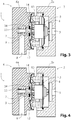
- the figures 2 and 3 represent in longitudinal section a device (1) pneumatic, controlled and sealed inflation-deflation of a confinement capacity, such as a vehicle wheel tire for example.
- the device (1) comprises, in a well-known manner, two parts defining two chambers.
- the first part (2) is in the form of a hollow body (2a), for example cylindrical.
- the first chamber (4) defined inside the hollow body (2a) communicates with the outside of the device (1) through an inlet (5) formed in one of the circular bases of said cylindrical hollow body (2a).
- This inlet (5) is intended to receive injection means (not shown) of a gaseous fluid under pressure, for example compressed air.
- the first part (2) comprises a control system (3) slidably mounted in the first chamber (4) under the effect of the injection of a pressurized gaseous fluid through said inlet orifice (5).
- the control system (3) protrudes from the other end of the hollow body (2a), opposite the inlet (5), and is secured to a valve (10).
- the base of the cylindrical hollow body (2a), from which the control system (3) projects, comprises a annular protuberance (13) arranged concentrically with respect to said control system (3), and with respect to the generatrix of the cylindrical hollow body (2a).
- the second part (6) of the device (1) is coupled in any suitable manner to the first part (2), and is in the same way as the first part (2) in the form of a hollow body ( 6a), preferably cylindrical.
- the second chamber (7) defined inside the hollow body (6a) communicates, on the one hand, with a confinement capacity of a gas under pressure (not shown), such as a tire of a wheel of a vehicle for example, and through an inflation-deflation orifice (8) and, on the other hand, with the outside of the device (1) through an exhaust port (9) .
- the exhaust port (9) is formed in the axis of the generatrix of the cylindrical hollow body (2a) of the first part (2).
- the exhaust port (9) faces the piloting system (3), and in particular allows the expulsion of a gaseous fluid from the second chamber (7) between the first and second parts (2, 6). , and more particularly from the capacity through the inflation-deflation orifice (8).
- the second part (6) comprises a valve (10) adapted to adopt a rest position in which it closes the exhaust port (9), and an inflation-deflation position, against an elastic member a spring (11), in which it releases said exhaust port (9).
- valve (10) is subjected to the control system (3), through the exhaust port (9), so that when the control system (3) slides towards the valve (10), said valve (10) is pushed by the control system (3) and slid to release said exhaust port (9).
- the second part (6) comprises, on one side opposite the first part (2), a profiled groove (14) arranged concentrically with the exhaust orifice (9), and in correspondence with the annular protuberance ( 13) of the first part (2).
- This profiled groove (14) comprises a transverse profile in the shape of a "V”.
- This groove (14) receives a protective washer (12).
- the protective washer (12) is made of elastomeric material, and is arranged in the receiving groove (14), concentrically with the exhaust port (9), and bearing on said second portion (6). More specifically, the washer (12) is arranged in the second portion (6) so that said second portion (6) exerts circumferential supports at the inner and outer perimeters of the washer (12). More specifically, the outer zone of the groove (14), namely the outer branch of the "V” makes it possible to achieve the external circumferential support and, in the same way, the internal zone of the groove (14), namely the internal branch of the "V” makes it possible to carry out the internal circumferential support.
- the first and second parts (2, 6) are arranged in such a way that the annular protuberance (13) of the first part (2) bears against the said protective washer (12).
- the support is forced so that the washer (12) is forced to deform elastically and in particular to bend towards the second portion (6).
- This washer (12) in combination with the contact of the annular protrusion (13) makes it possible to seal the device (1) and to protect it against splashes of mud, water, dust or any other undesirable element. Forced pressing between the washer (12) and the annular protuberance (13) further optimizes this seal.
- the washer (12) rests on the one hand against the second part (6) and on the inner and outer perimeters of said washer (12), and on the other hand, against the first part (2) and against the surface of the washer (12) defined between said inner and outer perimeters.
- the washer (12) During the expulsion of the fluid under pressure, that is to say during the deflation of a tire of a vehicle wheel for example, the washer (12) remains pressed against the second portion (6) under the effect of the force exerted by the pressure of the escaping fluid. In this way, the washer (12) does not vibrate and generates no nuisance unwanted sound.
- the "V" shape of the profiled groove (14) frees a space allowing the washer (12) to deform elastically and bend towards said second portion (6). When the washer (12) bends, it does not hit any part violently. Thus no shock or violent noise is generated.
- the invention provides a device (1) inflation-deflation sealed, and whose noise generated by its operation is reduced.
- a device (1) can, advantageously, equip military vehicles without harming their stealth.
- the device (1) according to the invention is simple in design, safe and rational.
Description
La présente invention concerne le domaine technique des dispositifs permettant un gonflage-dégonflage automatique d'une capacité, par exemple d'un pneumatique d'une roue de véhicule, à partir d'un fluide gazeux sous pression relative.The present invention relates to the technical field of devices for automatically inflating-deflating a capacity, for example of a tire of a vehicle wheel, from a gaseous fluid under relative pressure.
En effet, il est parfois utile de pouvoir gonfler ou dégonfler à distance les pneumatiques des roues d'un véhicule, de manière à pouvoir adapter la portance de ces derniers en fonction de l'état du sol sur lequel le véhicule se déplace.Indeed, it is sometimes useful to inflate or deflate remotely the tires of the wheels of a vehicle, so as to adapt the lift of the latter according to the state of the ground on which the vehicle moves.
Ceci est, en particulier, le cas des véhicules tous terrains qui doivent pouvoir progresser dans les meilleures conditions, indifféremment, sur des sols durs, caillouteux, meubles, se succédant, sans que le conducteur soit astreint à interrompre la progression pour apporter, de façon manuelle et lorsque le véhicule est à l'arrêt, une correction appropriée de la pression de gonflage des différents pneumatiques.This is, in particular, the case of all-terrain vehicles which must be able to progress under the best conditions, indifferently, on hard, stony, loose, and succeeding floors, without the driver having to interrupt the progression in order to manual and when the vehicle is stationary, an appropriate correction of the inflation pressure of the various tires.
Cette application n'est donnée qu'à titre d'exemple car, dans de nombreux domaines, il s'avère également utile, sinon nécessaire, de pouvoir adapter à distance la pression de gonflage d'une capacité quelconque de confinement d'un fluide gazeux sous pression relative.This application is only given by way of example because, in many fields, it is also useful, if not necessary, to be able to adapt the inflation pressure remotely to any capacity for confining a fluid. gaseous under relative pressure.
Pour résoudre le problème ci-dessus, il est connu de l'état de la technique d'utiliser un dispositif (1) de gonflage-dégonflage automatique d'une capacité. En référence aux
- une première partie (2) comprenant un système de pilotage (3) monté coulissant dans une première chambre (4) sous l'effet de l'injection d'un fluide gazeux par un orifice d'admission (5) ;
- une deuxième partie (6), accouplée à la première partie (2), et définissant une deuxième chambre (7) avec un orifice de gonflage-dégonflage (8) destiné à communiquer avec la capacité de confinement (non représentée), et un orifice d'échappement (9) débouchant entre lesdites première et deuxième parties (2, 6), ladite deuxième partie (6) comprenant un clapet (10) assujetti au système de pilotage (3) de manière à adopter une position de repos dans laquelle il obture l'orifice d'échappement (9), et une position de dégonflage, à l'encontre d'un organe élastique de rappel (11) et lorsque le système de pilotage (3) coulisse, dans laquelle il libère l'orifice d'échappement (9).
- a first portion (2) comprising a control system (3) slidably mounted in a first chamber (4) under the effect of the injection of a gaseous fluid through an inlet (5);
- a second portion (6), coupled to the first portion (2), and defining a second chamber (7) with an inflation-deflation port (8) for communicating with the containment capability (not shown), and an orifice exhaust (9) opening between said first and second parts (2, 6), said second part (6) comprising a valve (10) secured to the control system (3) so as to adopt a rest position in which it closes the exhaust port (9), and a deflation position, against an elastic return member (11) and when the control system (3) slides, wherein it releases the exhaust port (9).
Ce dispositif permet, par l'injection d'un fluide gazeux, d'entrainer le coulissement du système de pilotage et donc de piloter le clapet pour libérer l'orifice d'échappement pour le dégonflage de la capacité de confinement.This device makes it possible, by injecting a gaseous fluid, to drive the sliding of the control system and thus to drive the valve to release the exhaust orifice for deflation of the confinement capacity.
Ce dispositif peut, par exemple, être monté sur des véhicules tous terrains, lesquels circulent dans des flaques d'eau, dans de la poussière, et/ou de la boue. Les projections de poussières, boue, eau peuvent pénétrer dans le dispositif de gonflage-dégonflage et l'endommager.This device can, for example, be mounted on off-road vehicles, which circulate in puddles of water, in dust, and / or mud. The projections of dust, mud, water can penetrate into the inflator-deflation device and damage it.
Pour pallier à cet inconvénient, il est connu de l'état de la technique d'intégrer une rondelle de protection (12). Cette rondelle (12), de préférence en matériau élastomère, est montée entre les première et deuxième parties (2, 6) et autour de l'orifice d'échappement (9) pour le protéger contre des agents atmosphériques extérieurs, tels que boue, eau, poussières, ou tout autre élément indésirable pouvant nuire au fonctionnement du dispositif.To overcome this drawback, it is known from the state of the art to incorporate a protective washer (12). This washer (12), preferably of elastomeric material, is mounted between the first and second parts (2, 6) and around the exhaust port (9) to protect it against external atmospheric agents, such as sludge, water, dust, or any other undesirable element that may impair the operation of the device.
Plus précisément, cette rondelle (12) comprend une forme en tronc de cône, dont la petite base (12a), à savoir le périmètre interne de la rondelle (12), est en appui étanche contre la première partie (2), et la grande base (12b), à savoir le périmètre externe de la rondelle (12), est en appui étanche contre la deuxième partie (6).More specifically, this washer (12) comprises a truncated cone shape, the small base (12a), namely the inner perimeter of the washer (12), is in sealing engagement against the first portion (2), and the large base (12b), namely the outer perimeter of the washer (12) is in sealing abutment against the second part (6).
Cette rondelle (12) permet de maintenir l'étanchéité du dispositif (1) et d'assurer une protection optimale contre les projections de boue, eau, poussière, ou tout autre élément.This washer (12) makes it possible to maintain the tightness of the device (1) and to provide optimum protection against splashes of mud, water, dust or any other element.
Cependant, cette solution pour assurer l'étanchéité présente un inconvénient majeur. En effet, lorsque la capacité de confinement est dégonflée, c'est-à-dire lorsque du fluide gazeux, notamment de l'air, est expulsé du dispositif, et s'échappe par l'orifice d'échappement, la rondelle en matériau élastomère est repliée pour laisser l'air s'échapper entre ladite rondelle et la deuxième partie. En d'autres termes, la grande base du tronc de cône est repoussée en direction de la petite base. La grande base, ayant perdu son appui, se trouve dans le vide. En fonction de la pression du fluide gazeux qui est libéré, la rondelle en matériau élastomère entre en vibration ce qui provoque une nuisance sonore non négligeable.However, this solution for sealing has a major disadvantage. Indeed, when the confinement capacity is deflated, that is to say when gaseous fluid, including air, is expelled from the device, and escapes through the exhaust port, the washer material elastomer is folded to allow air to escape between said washer and the second portion. In other words, the large base of the truncated cone is pushed towards the small base. The big base, having lost its support, find in the void. Depending on the pressure of the gaseous fluid that is released, the washer of elastomeric material vibrates which causes a significant noise nuisance.
Ces nuisances sonores peuvent être relativement gênantes dans certains domaines, notamment lorsqu'il s'agit d'équiper des véhicules devant faire preuve d'une certaine furtivité, par exemple pour des véhicules militaires.This noise can be relatively troublesome in some areas, especially when it comes to equipping vehicles to show a certain stealth, for example for military vehicles.
Les documents
L'un des buts de l'invention est donc de remédier au moins à l'inconvénient précité en proposant un dispositif de gonflage-dégonflage d'une capacité qui soit protégé contre des agents atmosphériques extérieurs, et dont la nuisance sonore engendrée par son fonctionnement est diminuée pour ne plus être gênante.One of the aims of the invention is therefore to remedy at least the aforementioned drawback by proposing an inflation-deflation device with a capacity that is protected against external atmospheric agents, and whose noise nuisance generated by its operation. is diminished to no longer be troublesome.
Un autre objectif de l'invention est de fournir un tel dispositif qui soit de conception simple, sûre et rationnelle.Another object of the invention is to provide such a device which is simple in design, safe and rational.
A cet effet, il a donc été mis au point un dispositif de gonflage-dégonflage automatique d'une capacité de confinement d'un fluide gazeux sous pression, du type comprenant :
- une partie comprenant un orifice d'admission d'un fluide gazeux sous pression, et une partie comprenant, un orifice de gonflage-dégonflage destiné à communiquer avec la capacité de confinement, et un orifice d'échappement débouchant entre lesdites deux parties ;
- un système de pilotage à clapet pour des opérations de gonflage-dégonflage en tant que telles ;
- une rondelle élastique montée entre les deux parties et autour de l'orifice d'échappement pour le protéger contre des agents atmosphériques extérieurs.
- a portion comprising an inlet for a gaseous fluid under pressure, and a portion comprising, an inflation-deflation orifice for communicating with the confinement capacity, and an exhaust port opening between said two parts;
- a valve control system for inflation-deflation operations as such;
- a spring washer mounted between the two parts and around the exhaust port to protect it against external atmospheric agents.
Conformément à l'invention, et pour assurer une étanchéité optimale, tout en réduisant les nuisances sonores dues au fonctionnement du dispositif, l'une des parties comprend des agencements de réception de la rondelle aptes à autoriser ladite rondelle à se déformer élastiquement, sous l'effet d'une pression d'un fluide gazeux s'échappant à travers l'orifice d'échappement, pour se libérer d'un appui facial réalisé par une protubérance annulaire que comprend l'autre partie, et créer un passage d'échappement de fluide entre ladite protubérance annulaire et ladite rondelle.In accordance with the invention, and to ensure optimum sealing, while reducing noise nuisance due to the operation of the device, one of the parts comprises receiving arrangements of the washer adapted to allow said washer to deform elastically under the the effect of a pressure of a gaseous fluid escaping through the exhaust orifice, to release a facial support made by an annular protuberance that comprises the other part, and to create an exhaust passage of fluid between said annular protuberance and said washer.
De cette manière, lorsque la capacité de confinement est dégonflée, c'est-à-dire lorsque du fluide gazeux s'échappe par l'orifice d'échappement, celui-ci contraint la rondelle de protection à se déformer élastiquement, et notamment à se courber dans les agencements de réception. De cette manière le fluide sous pression est apte à s'échapper par un passage libéré entre ladite rondelle et la saille annulaire. Par le terme « courber », on entend que la surface de la rondelle, définie entre le périmètre interne et le périmètre externe, prend une forme concave par rapport aux agencements de réception. Ainsi, la rondelle n'entre pas en vibration et ne génère aucune nuisance sonore non désirée. De plus, lors du dégonflage, le mouvement de la rondelle consiste uniquement en un mouvement de courbure de sorte qu'aucune partie de la rondelle ne vient percuter une quelconque partie du dispositif. Le dispositif est de conception simple, sûre et rationnelleIn this way, when the confinement capacity is deflated, that is to say when gaseous fluid escapes through the exhaust orifice, it forces the protection washer to deform elastically, and particularly to bend in the receiving arrangements. In this way the pressurized fluid is able to escape through a passage released between said washer and the annular scar. By the term "bend" is meant that the surface of the washer, defined between the inner perimeter and the outer perimeter, takes a concave shape with respect to the receiving arrangements. Thus, the washer does not vibrate and generates no unwanted noise nuisance. In addition, during deflation, the movement of the washer is only a bending motion so that no part of the washer does not hit any part of the device. The device is simple in design, safe and rational
Selon une forme de réalisation particulière, les agencements de réception de la rondelle sont aptes à former, d'un premier côté de la rondelle, des zones d'appuis circonférentiels aux niveaux des périmètres interne et externe de ladite rondelle.According to a particular embodiment, the arrangements for receiving the washer are able to form, on a first side of the washer, circumferential bearing zones at the inner and outer perimeters of said washer.
L'appui circonférentiel sur les périmètres interne et externe de la rondelle, en combinaison avec la pression du fluide gazeux, empêche davantage la rondelle d'entrer en vibration et de générer une nuisance sonore non désirée.The circumferential support on the inner and outer perimeters of the washer, in combination with the pressure of the gaseous fluid, further prevents the washer from vibrating and generating an unwanted noise nuisance.
De préférence, et pour assurer une meilleure étanchéité, en position de repos, la protubérance annulaire est en appui forcé contre la rondelle de protection, contraignant cette dernière à se déformer élastiquement, notamment à se courber. Lors du dégonflage, le fluide gazeux sous pression qui s'échappe par l'orifice d'échappement contraint la rondelle à se courber davantage pour libérer le passage d'échappement.Preferably, and to ensure a better seal, in the rest position, the annular protuberance bears against the protective washer, forcing the latter to deform elastically, especially to bend. During deflation, the pressurized gaseous fluid escaping through the exhaust port causes the washer to bend further to release the exhaust passage.
Selon une forme de réalisation particulière, les agencements de réception de la rondelle se présentent sous la forme d'une gorge profilée.According to a particular embodiment, the arrangements for receiving the washer are in the form of a profiled groove.
Avantageusement, la gorge de réception comprend un profil transversal en forme de « V ». Ainsi, la zone externe de la gorge, à savoir la branche externe du « V » permet de réaliser un appui circonférentiel au niveau du périmètre externe de la rondelle, tandis que la zone interne de la gorge, à savoir la branche interne du « V » permet de réaliser un appui circonférentiel au niveau du périmètre interne de la rondelle.Advantageously, the receiving groove comprises a transverse profile in the shape of a "V". Thus, the outer zone of the groove, namely the outer branch of the "V" allows a circumferential support at the outer perimeter of the washer, while the inner zone of the groove, namely the inner branch of the "V" Allows a circumferential support at the inner perimeter of the washer.
D'autres caractéristiques et avantages de l'invention ressortiront clairement de la description qui en est réalisée ci-après, à titre indicatif et nullement limitatif, en référence aux figures annexées dans lesquelles :
- la
figure 1 est une représentation schématique en coupe longitudinale d'un dispositif de gonflage-dégonflage de l'état de la technique, et en position de repos ; - la
figure 2 est une représentation schématique similaire à celle de lafigure 1 , le dispositif état en position de dégonflage ; - la
figure 3 est une représentation schématique en coupe longitudinale d'un dispositif de gonflage-dégonflage selon l'invention et en position de repos ; - la
figure 4 est une représentation schématique similaire à celle de lafigure 3 , le dispositif étant en position de dégonflage.
- the
figure 1 is a schematic representation in longitudinal section of a inflation-deflation device of the state of the art, and in the rest position; - the
figure 2 is a schematic representation similar to that of thefigure 1 the state device in the deflation position; - the
figure 3 is a schematic representation in longitudinal section of an inflation-deflation device according to the invention and in the rest position; - the
figure 4 is a schematic representation similar to that of thefigure 3 , the device being in the deflation position.
Par simplification, les parties ou éléments qui se retrouvent de manière identique ou similaire dans l'invention décrite ci-dessous, et dans l'état de la technique illustré aux
Les
La première partie (2) se présente sous la forme d'un corps creux (2a), par exemple cylindrique. La première chambre (4) définie à l'intérieur du corps creux (2a) communique avec l'extérieur du dispositif (1) par un orifice d'admission (5) ménagé dans l'une des bases circulaires dudit corps creux cylindrique (2a). Cet orifice d'admission (5) est destiné à recevoir des moyens d'injection (non représentés) d'un fluide gazeux sous pression, par exemple de l'air comprimé.The first part (2) is in the form of a hollow body (2a), for example cylindrical. The first chamber (4) defined inside the hollow body (2a) communicates with the outside of the device (1) through an inlet (5) formed in one of the circular bases of said cylindrical hollow body (2a). ). This inlet (5) is intended to receive injection means (not shown) of a gaseous fluid under pressure, for example compressed air.
La première partie (2) comprend un système de pilotage (3) monté coulissant dans la première chambre (4) sous l'effet de l'injection d'un fluide gazeux sous pression par ledit orifice d'admission (5). Le système de pilotage (3) fait saillie à l'autre extrémité du corps creux (2a), opposée à l'orifice d'admission (5), et est assujetti à un clapet (10). La base du corps creux cylindrique (2a), d'où fait saillie le système de pilotage (3), comprend une protubérance annulaire (13) agencée de manière concentrique par rapport audit système de pilotage (3), et par rapport à la génératrice du corps creux cylindrique (2a).The first part (2) comprises a control system (3) slidably mounted in the first chamber (4) under the effect of the injection of a pressurized gaseous fluid through said inlet orifice (5). The control system (3) protrudes from the other end of the hollow body (2a), opposite the inlet (5), and is secured to a valve (10). The base of the cylindrical hollow body (2a), from which the control system (3) projects, comprises a annular protuberance (13) arranged concentrically with respect to said control system (3), and with respect to the generatrix of the cylindrical hollow body (2a).
La deuxième partie (6) du dispositif (1) est accouplée de toute manière appropriée à la première partie (2), et se présente, de la même manière que la première partie (2), sous la forme d'un corps creux (6a), de préférence cylindrique. La deuxième chambre (7) définie à l'intérieur du corps creux (6a) communique, d'une part, avec une capacité de confinement d'un gaz sous pression (non représentée), tel qu'un pneumatique d'une roue d'un véhicule par exemple, et par le biais d'un orifice de gonflage-dégonflage (8) et, d'autre part, avec l'extérieur du dispositif (1) par le biais d'un orifice d'échappement (9). L'orifice d'échappement (9) est ménagé dans l'axe de la génératrice du corps creux cylindrique (2a) de la première partie (2). L'orifice d'échappement (9) est en regard du système de pilotage (3), et permet notamment d'expulser, entre les première et deuxième parties (2, 6), un fluide gazeux provenant de la deuxième chambre (7), et provenant plus particulièrement de la capacité par le biais de l'orifice de gonflage-dégonflage (8).The second part (6) of the device (1) is coupled in any suitable manner to the first part (2), and is in the same way as the first part (2) in the form of a hollow body ( 6a), preferably cylindrical. The second chamber (7) defined inside the hollow body (6a) communicates, on the one hand, with a confinement capacity of a gas under pressure (not shown), such as a tire of a wheel of a vehicle for example, and through an inflation-deflation orifice (8) and, on the other hand, with the outside of the device (1) through an exhaust port (9) . The exhaust port (9) is formed in the axis of the generatrix of the cylindrical hollow body (2a) of the first part (2). The exhaust port (9) faces the piloting system (3), and in particular allows the expulsion of a gaseous fluid from the second chamber (7) between the first and second parts (2, 6). , and more particularly from the capacity through the inflation-deflation orifice (8).
La deuxième partie (6) comprend un clapet (10) apte à adopter une position de repos dans laquelle il obture l'orifice d'échappement (9), et une position de gonflage-dégonflage, à l'encontre d'un organe élastique de rappel (11), tel qu'un ressort, dans laquelle il libère ledit orifice d'échappement (9).The second part (6) comprises a valve (10) adapted to adopt a rest position in which it closes the exhaust port (9), and an inflation-deflation position, against an elastic member a spring (11), in which it releases said exhaust port (9).
Le clapet (10) est assujetti au système de pilotage (3), au travers de l'orifice d'échappement (9), de sorte que lorsque le système de pilotage (3) coulisse en direction du clapet (10), ledit clapet (10) est poussé par le système de pilotage (3) et coulissé pour libérer ledit orifice d'échappement (9).The valve (10) is subjected to the control system (3), through the exhaust port (9), so that when the control system (3) slides towards the valve (10), said valve (10) is pushed by the control system (3) and slid to release said exhaust port (9).
La deuxième partie (6) comprend, sur une face en regard avec la première partie (2), une gorge profilée (14) agencée de manière concentrique à l'orifice d'échappement (9), et en correspondance avec la protubérance annulaire (13) de la première partie (2). Cette gorge profilée (14) comprend un profil transversal en forme de « V ». Cette gorge (14) reçoit une rondelle de protection (12).The second part (6) comprises, on one side opposite the first part (2), a profiled groove (14) arranged concentrically with the exhaust orifice (9), and in correspondence with the annular protuberance ( 13) of the first part (2). This profiled groove (14) comprises a transverse profile in the shape of a "V". This groove (14) receives a protective washer (12).
La rondelle de protection (12) est en matériau élastomère, et est agencée dans la gorge de réception (14), de manière concentrique à l'orifice d'échappement (9), et en appui sur ladite deuxième partie (6). Plus précisément, la rondelle (12) est agencée dans la deuxième partie (6) de sorte à ce que ladite deuxième partie (6) exerce des appuis circonférentiels aux niveaux des périmètres interne et externe de la rondelle (12). Plus précisément, la zone externe de la gorge (14), à savoir la branche externe du « V » permet de réaliser l'appui circonférentiel externe et, de la même manière, la zone interne de la gorge (14), à savoir la branche interne du « V » permet de réaliser l'appui circonférentiel interne.The protective washer (12) is made of elastomeric material, and is arranged in the receiving groove (14), concentrically with the exhaust port (9), and bearing on said second portion (6). More specifically, the washer (12) is arranged in the second portion (6) so that said second portion (6) exerts circumferential supports at the inner and outer perimeters of the washer (12). More specifically, the outer zone of the groove (14), namely the outer branch of the "V" makes it possible to achieve the external circumferential support and, in the same way, the internal zone of the groove (14), namely the internal branch of the "V" makes it possible to carry out the internal circumferential support.
Les première et deuxième parties (2, 6) sont agencées de telle sorte que la protubérance annulaire (13) de la première partie (2) est en appui facial contre ladite rondelle de protection (12). De préférence, l'appui est forcé de sorte que la rondelle (12) est contrainte à se déformer élastiquement et notamment à se courber en direction de la deuxième partie (6).The first and second parts (2, 6) are arranged in such a way that the annular protuberance (13) of the first part (2) bears against the said protective washer (12). Preferably, the support is forced so that the washer (12) is forced to deform elastically and in particular to bend towards the second portion (6).
De cette manière, l'orifice d'échappement (9), le système de pilotage (3), et plus généralement l'intérieur du dispositif (1), sont confinés de manière étanche dans un espace défini entre la protubérance annulaire (13) et la rondelle de protection (12).In this way, the exhaust port (9), the control system (3), and more generally the interior of the device (1), are sealed in a space defined between the annular protuberance (13) and the protection washer (12).
Cette rondelle (12), en combinaison avec le contact de la protubérance annulaire (13) permet d'assurer l'étanchéité du dispositif (1) et de le protéger contre les projections de boue, d'eau, de poussières ou de tout autre élément indésirable. L'appui forcé entre la rondelle (12) et la protubérance annulaire (13) permet d'optimiser davantage cette étanchéité.This washer (12), in combination with the contact of the annular protrusion (13) makes it possible to seal the device (1) and to protect it against splashes of mud, water, dust or any other undesirable element. Forced pressing between the washer (12) and the annular protuberance (13) further optimizes this seal.
En position de repos, la rondelle (12) se trouve en appui, d'une part, contre la deuxième partie (6) et aux niveaux des périmètres interne et externe de ladite rondelle (12), et, d'autre part, contre la première partie (2) et contre la surface de la rondelle (12) définie entre lesdits périmètres interne et externe.In the rest position, the washer (12) rests on the one hand against the second part (6) and on the inner and outer perimeters of said washer (12), and on the other hand, against the first part (2) and against the surface of the washer (12) defined between said inner and outer perimeters.
Lorsqu'il s'agit de dégonfler une capacité connectée au dispositif (1) par l'intermédiaire de l'orifice de gonflage-dégonflage (8), il suffit d'injecter un fluide sous pression par l'orifice d'admission (5). Ce fluide sous pression entraine le coulissement du système de pilotage (3) en direction de la deuxième partie (6). Le coulissement du système de pilotage (3) entraine le coulissement du clapet (10), à l'encontre de l'organe élastique de rappel (11), de manière à libérer l'orifice d'échappement (9). Le fluide sous pression présent dans la capacité s'échappe alors par l'orifice d'échappement (9), et se retrouve dans l'espace défini entre la protubérance annulaire (13) et la rondelle de protection (12). La pression du fluide qui s'échappe contraint la rondelle (12) en matériau élastomère à se déformer élastiquement, et notamment à se courber davantage, pour se libérer de l'appui de la protubérance annulaire (13), et libérer ainsi un passage d'échappement de fluide.When it comes to deflating a capacitor connected to the device (1) via the inflation-deflation orifice (8), it suffices to inject a fluid under pressure through the inlet orifice (5). ). This fluid under pressure causes the sliding of the control system (3) towards the second part (6). The sliding of the control system (3) causes the sliding of the valve (10), against the elastic return member (11), so as to release the exhaust port (9). The fluid under pressure present in the capacity then escapes through the exhaust port (9), and is found in the space defined between the annular protuberance (13) and the protective washer (12). The pressure of the fluid that escapes forces the washer (12) of elastomeric material to deform elastically, and in particular to bend more, to release the support of the annular protrusion (13), and thus release a passage of exhaust fluid.
Lors de l'expulsion du fluide sous pression, c'est-à-dire lors du dégonflage d'un pneumatique d'une roue de véhicule par exemple, la rondelle (12) reste plaquée contre la deuxième partie (6) sous l'effet de la force exercée par la pression du fluide qui s'échappe. De cette manière, la rondelle (12) n'entre pas en vibration et ne génère aucune nuisance sonore non désirée.During the expulsion of the fluid under pressure, that is to say during the deflation of a tire of a vehicle wheel for example, the washer (12) remains pressed against the second portion (6) under the effect of the force exerted by the pressure of the escaping fluid. In this way, the washer (12) does not vibrate and generates no nuisance unwanted sound.
Par ailleurs, la forme en « V » de la gorge profilée (14) permet de libérer un espace autorisant la rondelle (12) à se déformer élastiquement et se courber en direction de ladite deuxième partie (6). Lorsque la rondelle (12) se courbe, celle-ci ne percute aucune partie de manière violente. Ainsi aucun choc ou bruit violent n'est généré.Furthermore, the "V" shape of the profiled groove (14) frees a space allowing the washer (12) to deform elastically and bend towards said second portion (6). When the washer (12) bends, it does not hit any part violently. Thus no shock or violent noise is generated.
Comme il ressort de ce qui précède, l'invention fournit un dispositif (1) de gonflage-dégonflage étanche, et dont la nuisance sonore engendrée par son fonctionnement est diminuée. Un tel dispositif (1) peut, d'une manière avantageuse, équiper des véhicules militaires sans nuire à leur furtivité. Le dispositif (1) selon l'invention est de conception simple, sûre et rationnelle.As is apparent from the foregoing, the invention provides a device (1) inflation-deflation sealed, and whose noise generated by its operation is reduced. Such a device (1) can, advantageously, equip military vehicles without harming their stealth. The device (1) according to the invention is simple in design, safe and rational.
Claims (5)
- An inflation/deflation device (1) for automatically inflating/deflating a closed volume for confining a gaseous fluid under pressure, said device (1) comprising:- a portion (2) provided with an intake orifice (5) for taking in a gaseous fluid under pressure, and a portion (6) provided with an inflation/deflation orifice (8) designed to communicate with the closed volume, and provided with a discharge orifice (9) opening out between the two portions (2, 6);- a valve member control system (3, 10) for inflation/deflation operations per se; and- an elastically deformable washer (12) mounted between the two portions (2, 6) and around the discharge orifice (9) for protecting it from external atmospheric agents;characterized in that one of the portions (6) is provided with arrangements (14) for receiving the washer (12), that are capable of allowing said washer (12) to deform elastically, under the effect of a pressure of a gaseous fluid discharging through the discharge orifice (9), so as to release face-on abutment created by an annular protuberance (13) provided on the other portion (2), and so as to generate a fluid discharge passage between said annular protuberance (13) and said washer (12).
- An inflation/deflation device (1) according to claim 1, characterized in that the arrangements (14) for receiving the washer (12) are capable of forming, on a first side of the washer, circumferential bearing zones at the inner and outer perimeters of said washer (12).
- An inflation/deflation device (1) according to any preceding claim, characterized in that, when the valve is in the rest position, the protuberance (13) bears in forced manner against the washer (12), thereby constraining said washer to deform elastically.
- An inflation/deflation device (1) according to any preceding claim, characterized in that the washer-receiving arrangements are in the form of a profiled groove (14).
- A device (1) according to claim 4, characterized in that the groove (14) is V-shaped in cross-section.
Priority Applications (1)
| Application Number | Priority Date | Filing Date | Title |
|---|---|---|---|
| PL15725826T PL3142872T3 (en) | 2014-05-13 | 2015-05-06 | Device for automatic inflation-deflation of a containment capacity for a pressurised gaseous fluid |
Applications Claiming Priority (2)
| Application Number | Priority Date | Filing Date | Title |
|---|---|---|---|
| FR1454228A FR3020991B1 (en) | 2014-05-13 | 2014-05-13 | AUTOMATIC INFLATION-DEFLATION DEVICE FOR CONTAINING CAPACITY OF A GASEOUS FLUID UNDER PRESSURE |
| PCT/FR2015/051199 WO2015173493A1 (en) | 2014-05-13 | 2015-05-06 | Device for automatic inflation-deflation of a containment capacity for a pressurised gaseous fluid |
Publications (2)
| Publication Number | Publication Date |
|---|---|
| EP3142872A1 EP3142872A1 (en) | 2017-03-22 |
| EP3142872B1 true EP3142872B1 (en) | 2018-01-31 |
Family
ID=51168202
Family Applications (1)
| Application Number | Title | Priority Date | Filing Date |
|---|---|---|---|
| EP15725826.0A Active EP3142872B1 (en) | 2014-05-13 | 2015-05-06 | Device for automatic inflation-deflation of a containment capacity for a pressurised gaseous fluid |
Country Status (11)
| Country | Link |
|---|---|
| US (1) | US10197173B2 (en) |
| EP (1) | EP3142872B1 (en) |
| CN (1) | CN106461116B (en) |
| AU (1) | AU2015261364B2 (en) |
| BR (1) | BR112016024910B1 (en) |
| CA (1) | CA2948986C (en) |
| ES (1) | ES2658820T3 (en) |
| FR (1) | FR3020991B1 (en) |
| PL (1) | PL3142872T3 (en) |
| RU (1) | RU2674421C2 (en) |
| WO (1) | WO2015173493A1 (en) |
Families Citing this family (1)
| Publication number | Priority date | Publication date | Assignee | Title |
|---|---|---|---|---|
| EP3402684B1 (en) * | 2016-01-13 | 2019-12-04 | Dana Heavy Vehicle Systems Group, LLC | Valve assembly for a tire pressure management system |
Family Cites Families (18)
| Publication number | Priority date | Publication date | Assignee | Title |
|---|---|---|---|---|
| US2156841A (en) * | 1938-04-09 | 1939-05-02 | Walter H Davis | Tire pressure controlling apparatus |
| US3491786A (en) | 1968-02-26 | 1970-01-27 | Goodyear Tire & Rubber | Tire inflation and pressure control valve |
| US3747626A (en) | 1971-05-05 | 1973-07-24 | J Valentino | Combined check and relief valve |
| US4895199A (en) | 1986-07-31 | 1990-01-23 | Paccar Inc | Tire inflation and deflation valve |
| US4744399A (en) * | 1986-07-31 | 1988-05-17 | Paccar Inc. | Central tire inflation system |
| US4765385A (en) * | 1987-02-27 | 1988-08-23 | Numatics, Incorporated | Tire inflation-deflation system |
| US5181977A (en) * | 1988-09-09 | 1993-01-26 | Circle Seal Controls, Inc. | Tire inflation valve having overpressure and flow control |
| US4938272A (en) * | 1989-01-26 | 1990-07-03 | General Motors Corporation | Valve actuator for tire pressure management |
| FR2675744B1 (en) * | 1991-04-23 | 1995-05-19 | Stephane Fazekas | PILOT PNEUMATIC DEVICE FOR AUTOMATIC INFLATION-DEFLATION OF A CONTAINMENT CAPACITY OF A GAS FLUID UNDER RELATIVE PRESSURE. |
| ATE274160T1 (en) * | 2000-12-28 | 2004-09-15 | Col Ven Sa | THREE WAY PRESSURE REGULATOR VALVE |
| FR2822918B1 (en) * | 2001-03-30 | 2003-06-13 | Henri Beau | PNEUMATIC PILOT DEVICE FOR AUTOMATIC INFLATION-DEFLATION OF A CONTAINMENT CAPACITY OF A GAS FLUID UNDER RELATIVE PRESSURE |
| US7104274B2 (en) | 2002-10-07 | 2006-09-12 | William Darcy Sampson | Fluid control apparatus |
| JP4049376B2 (en) | 2003-06-23 | 2008-02-20 | 太平洋工業株式会社 | Relief valve |
| WO2007134611A1 (en) * | 2006-05-24 | 2007-11-29 | Opfinderfabrikken Aps | A pressure relief device for an inflatable tire |
| DE102007036201B4 (en) | 2007-08-02 | 2021-06-02 | Michel Maquaire | Free-wheeling valve for vehicles with tire pressure control |
| US8113234B2 (en) | 2007-10-15 | 2012-02-14 | Flow-Rite Controls, Ltd. | Stem-mounted tire inflation pressure regulator |
| CN201339733Y (en) * | 2008-12-29 | 2009-11-04 | 罗达莱克斯阀门(上海)有限公司 | Charging valve for motor vehicle |
| US8336571B2 (en) | 2009-05-27 | 2012-12-25 | Honeywell International Inc. | Overpressure shutoff and relief valve assembly |
-
2014
- 2014-05-13 FR FR1454228A patent/FR3020991B1/en not_active Expired - Fee Related
-
2015
- 2015-05-06 CA CA2948986A patent/CA2948986C/en active Active
- 2015-05-06 WO PCT/FR2015/051199 patent/WO2015173493A1/en active Application Filing
- 2015-05-06 AU AU2015261364A patent/AU2015261364B2/en active Active
- 2015-05-06 EP EP15725826.0A patent/EP3142872B1/en active Active
- 2015-05-06 ES ES15725826.0T patent/ES2658820T3/en active Active
- 2015-05-06 PL PL15725826T patent/PL3142872T3/en unknown
- 2015-05-06 US US15/310,417 patent/US10197173B2/en active Active
- 2015-05-06 BR BR112016024910-0A patent/BR112016024910B1/en active IP Right Grant
- 2015-05-06 CN CN201580024293.XA patent/CN106461116B/en active Active
- 2015-05-06 RU RU2016144347A patent/RU2674421C2/en active
Also Published As
| Publication number | Publication date |
|---|---|
| CA2948986A1 (en) | 2015-11-19 |
| RU2674421C2 (en) | 2018-12-07 |
| AU2015261364A1 (en) | 2016-12-22 |
| US20170268683A1 (en) | 2017-09-21 |
| FR3020991B1 (en) | 2016-05-13 |
| CN106461116A (en) | 2017-02-22 |
| CN106461116B (en) | 2018-11-20 |
| CA2948986C (en) | 2021-10-26 |
| EP3142872A1 (en) | 2017-03-22 |
| RU2016144347A3 (en) | 2018-10-16 |
| ES2658820T3 (en) | 2018-03-12 |
| BR112016024910A2 (en) | 2017-08-15 |
| BR112016024910B1 (en) | 2021-01-19 |
| PL3142872T3 (en) | 2018-04-30 |
| FR3020991A1 (en) | 2015-11-20 |
| AU2015261364B2 (en) | 2018-10-04 |
| WO2015173493A1 (en) | 2015-11-19 |
| US10197173B2 (en) | 2019-02-05 |
| RU2016144347A (en) | 2018-05-11 |
Similar Documents
| Publication | Publication Date | Title |
|---|---|---|
| EP2755830B1 (en) | Controlled pneumatic device for automatically inflating/deflating a tyre | |
| EP2180207B1 (en) | Vibration isolator and vehicle provided with such an isolator | |
| BE1009965A3 (en) | Core. | |
| EP2303609B1 (en) | Purging device for assembled unit and method of deflating an assembled unit | |
| EP3142872B1 (en) | Device for automatic inflation-deflation of a containment capacity for a pressurised gaseous fluid | |
| EP3072676A1 (en) | Secure gas spring device | |
| EP2739490B1 (en) | Rotary sealing device, and sealing ring for such a device | |
| FR2563739A1 (en) | COMPENSATED VALVE FOR RESPIRATORY GAS SUPPLY DEVICE | |
| FR2821140A1 (en) | PILOTED PNEUMATIC VALVE | |
| FR2747343A1 (en) | PLATE CORRECTION DEVICE FOR VEHICLES WITH SUSPENSION BY INFLATABLE ELASTIC CUSHIONS | |
| WO2018162380A1 (en) | Actuator for hydraulic or pneumatic control device | |
| FR2896725A1 (en) | Vehicle wheel valve for controlling tire inflation has friction-less piston between housing and cover creating pressure and control chambers | |
| FR3033855A1 (en) | BEARING, IN PARTICULAR FOR VEHICLE | |
| CA2689567A1 (en) | Purge valve for mounted assembly | |
| FR2887821A1 (en) | IMPROVEMENT OF ASSEMBLIES INCLUDING A BUCKLE FOR ROLLING INTO THE CONDITION. | |
| FR2766421A1 (en) | RUBBER SAFETY VALVE FOR WHEEL RIM COMPRISING A TIRE WITHOUT AIR TUBE | |
| EP3385566A1 (en) | Adaptive suspension device adjustable by needle discharge system | |
| FR3095681A1 (en) | Solenoid valve for cleaning system of an optical surface of a motor vehicle optical sensor | |
| FR2820085A1 (en) | Wheel rim for tire without air chamber has device for prevention of tire bursting due to over pressurization comprising hollow body containing tube with shell comprising cavity in which rod is supported | |
| FR2556295A1 (en) | Energy absorption device for mounting a bumper on a motor vehicle | |
| EP1216907A1 (en) | Improved brake actuation system with brake force booster and hydraulic reaction | |
| FR2684969A1 (en) | Container containing a fluid product to be dispensed and a compressed gas, provided with a safety device with a mobile obturating body | |
| FR2633879A1 (en) | Hydropneumatic suspension with built-in damper and automatic trim (attitude) correction | |
| FR2881981A1 (en) | Vehicle tire repairing device comprises a tank having product of vulcanization agent and propellant gas, and a distribution head | |
| BE357136A (en) |
Legal Events
| Date | Code | Title | Description |
|---|---|---|---|
| PUAI | Public reference made under article 153(3) epc to a published international application that has entered the european phase |
Free format text: ORIGINAL CODE: 0009012 |
|
| 17P | Request for examination filed |
Effective date: 20161019 |
|
| AK | Designated contracting states |
Kind code of ref document: A1 Designated state(s): AL AT BE BG CH CY CZ DE DK EE ES FI FR GB GR HR HU IE IS IT LI LT LU LV MC MK MT NL NO PL PT RO RS SE SI SK SM TR |
|
| AX | Request for extension of the european patent |
Extension state: BA ME |
|
| DAV | Request for validation of the european patent (deleted) | ||
| DAX | Request for extension of the european patent (deleted) | ||
| GRAP | Despatch of communication of intention to grant a patent |
Free format text: ORIGINAL CODE: EPIDOSNIGR1 |
|
| INTG | Intention to grant announced |
Effective date: 20171018 |
|
| GRAS | Grant fee paid |
Free format text: ORIGINAL CODE: EPIDOSNIGR3 |
|
| GRAA | (expected) grant |
Free format text: ORIGINAL CODE: 0009210 |
|
| RAP1 | Party data changed (applicant data changed or rights of an application transferred) |
Owner name: TELEFLOW |
|
| RIN1 | Information on inventor provided before grant (corrected) |
Inventor name: FAZEKAS, STEPHANE |
|
| AK | Designated contracting states |
Kind code of ref document: B1 Designated state(s): AL AT BE BG CH CY CZ DE DK EE ES FI FR GB GR HR HU IE IS IT LI LT LU LV MC MK MT NL NO PL PT RO RS SE SI SK SM TR |
|
| REG | Reference to a national code |
Ref country code: GB Ref legal event code: FG4D Free format text: NOT ENGLISH Ref country code: CH Ref legal event code: EP |
|
| REG | Reference to a national code |
Ref country code: AT Ref legal event code: REF Ref document number: 967004 Country of ref document: AT Kind code of ref document: T Effective date: 20180215 |
|
| REG | Reference to a national code |
Ref country code: IE Ref legal event code: FG4D Free format text: LANGUAGE OF EP DOCUMENT: FRENCH |
|
| REG | Reference to a national code |
Ref country code: DE Ref legal event code: R096 Ref document number: 602015007858 Country of ref document: DE |
|
| REG | Reference to a national code |
Ref country code: ES Ref legal event code: FG2A Ref document number: 2658820 Country of ref document: ES Kind code of ref document: T3 Effective date: 20180312 |
|
| REG | Reference to a national code |
Ref country code: FR Ref legal event code: PLFP Year of fee payment: 4 |
|
| REG | Reference to a national code |
Ref country code: NL Ref legal event code: MP Effective date: 20180131 |
|
| REG | Reference to a national code |
Ref country code: LT Ref legal event code: MG4D |
|
| REG | Reference to a national code |
Ref country code: AT Ref legal event code: MK05 Ref document number: 967004 Country of ref document: AT Kind code of ref document: T Effective date: 20180131 |
|
| PG25 | Lapsed in a contracting state [announced via postgrant information from national office to epo] |
Ref country code: HR Free format text: LAPSE BECAUSE OF FAILURE TO SUBMIT A TRANSLATION OF THE DESCRIPTION OR TO PAY THE FEE WITHIN THE PRESCRIBED TIME-LIMIT Effective date: 20180131 Ref country code: NL Free format text: LAPSE BECAUSE OF FAILURE TO SUBMIT A TRANSLATION OF THE DESCRIPTION OR TO PAY THE FEE WITHIN THE PRESCRIBED TIME-LIMIT Effective date: 20180131 Ref country code: NO Free format text: LAPSE BECAUSE OF FAILURE TO SUBMIT A TRANSLATION OF THE DESCRIPTION OR TO PAY THE FEE WITHIN THE PRESCRIBED TIME-LIMIT Effective date: 20180430 Ref country code: LT Free format text: LAPSE BECAUSE OF FAILURE TO SUBMIT A TRANSLATION OF THE DESCRIPTION OR TO PAY THE FEE WITHIN THE PRESCRIBED TIME-LIMIT Effective date: 20180131 |
|
| PG25 | Lapsed in a contracting state [announced via postgrant information from national office to epo] |
Ref country code: GR Free format text: LAPSE BECAUSE OF FAILURE TO SUBMIT A TRANSLATION OF THE DESCRIPTION OR TO PAY THE FEE WITHIN THE PRESCRIBED TIME-LIMIT Effective date: 20180501 Ref country code: BG Free format text: LAPSE BECAUSE OF FAILURE TO SUBMIT A TRANSLATION OF THE DESCRIPTION OR TO PAY THE FEE WITHIN THE PRESCRIBED TIME-LIMIT Effective date: 20180430 Ref country code: SE Free format text: LAPSE BECAUSE OF FAILURE TO SUBMIT A TRANSLATION OF THE DESCRIPTION OR TO PAY THE FEE WITHIN THE PRESCRIBED TIME-LIMIT Effective date: 20180131 Ref country code: IS Free format text: LAPSE BECAUSE OF FAILURE TO SUBMIT A TRANSLATION OF THE DESCRIPTION OR TO PAY THE FEE WITHIN THE PRESCRIBED TIME-LIMIT Effective date: 20180531 Ref country code: AT Free format text: LAPSE BECAUSE OF FAILURE TO SUBMIT A TRANSLATION OF THE DESCRIPTION OR TO PAY THE FEE WITHIN THE PRESCRIBED TIME-LIMIT Effective date: 20180131 Ref country code: LV Free format text: LAPSE BECAUSE OF FAILURE TO SUBMIT A TRANSLATION OF THE DESCRIPTION OR TO PAY THE FEE WITHIN THE PRESCRIBED TIME-LIMIT Effective date: 20180131 Ref country code: RS Free format text: LAPSE BECAUSE OF FAILURE TO SUBMIT A TRANSLATION OF THE DESCRIPTION OR TO PAY THE FEE WITHIN THE PRESCRIBED TIME-LIMIT Effective date: 20180131 |
|
| PG25 | Lapsed in a contracting state [announced via postgrant information from national office to epo] |
Ref country code: MT Free format text: LAPSE BECAUSE OF FAILURE TO SUBMIT A TRANSLATION OF THE DESCRIPTION OR TO PAY THE FEE WITHIN THE PRESCRIBED TIME-LIMIT Effective date: 20180131 |
|
| PG25 | Lapsed in a contracting state [announced via postgrant information from national office to epo] |
Ref country code: AL Free format text: LAPSE BECAUSE OF FAILURE TO SUBMIT A TRANSLATION OF THE DESCRIPTION OR TO PAY THE FEE WITHIN THE PRESCRIBED TIME-LIMIT Effective date: 20180131 Ref country code: RO Free format text: LAPSE BECAUSE OF FAILURE TO SUBMIT A TRANSLATION OF THE DESCRIPTION OR TO PAY THE FEE WITHIN THE PRESCRIBED TIME-LIMIT Effective date: 20180131 Ref country code: EE Free format text: LAPSE BECAUSE OF FAILURE TO SUBMIT A TRANSLATION OF THE DESCRIPTION OR TO PAY THE FEE WITHIN THE PRESCRIBED TIME-LIMIT Effective date: 20180131 |
|
| REG | Reference to a national code |
Ref country code: DE Ref legal event code: R097 Ref document number: 602015007858 Country of ref document: DE |
|
| PG25 | Lapsed in a contracting state [announced via postgrant information from national office to epo] |
Ref country code: SM Free format text: LAPSE BECAUSE OF FAILURE TO SUBMIT A TRANSLATION OF THE DESCRIPTION OR TO PAY THE FEE WITHIN THE PRESCRIBED TIME-LIMIT Effective date: 20180131 Ref country code: DK Free format text: LAPSE BECAUSE OF FAILURE TO SUBMIT A TRANSLATION OF THE DESCRIPTION OR TO PAY THE FEE WITHIN THE PRESCRIBED TIME-LIMIT Effective date: 20180131 Ref country code: SK Free format text: LAPSE BECAUSE OF FAILURE TO SUBMIT A TRANSLATION OF THE DESCRIPTION OR TO PAY THE FEE WITHIN THE PRESCRIBED TIME-LIMIT Effective date: 20180131 |
|
| PLBE | No opposition filed within time limit |
Free format text: ORIGINAL CODE: 0009261 |
|
| STAA | Information on the status of an ep patent application or granted ep patent |
Free format text: STATUS: NO OPPOSITION FILED WITHIN TIME LIMIT |
|
| 26N | No opposition filed |
Effective date: 20181102 |
|
| PG25 | Lapsed in a contracting state [announced via postgrant information from national office to epo] |
Ref country code: MC Free format text: LAPSE BECAUSE OF FAILURE TO SUBMIT A TRANSLATION OF THE DESCRIPTION OR TO PAY THE FEE WITHIN THE PRESCRIBED TIME-LIMIT Effective date: 20180131 |
|
| PG25 | Lapsed in a contracting state [announced via postgrant information from national office to epo] |
Ref country code: SI Free format text: LAPSE BECAUSE OF FAILURE TO SUBMIT A TRANSLATION OF THE DESCRIPTION OR TO PAY THE FEE WITHIN THE PRESCRIBED TIME-LIMIT Effective date: 20180131 |
|
| PG25 | Lapsed in a contracting state [announced via postgrant information from national office to epo] |
Ref country code: LU Free format text: LAPSE BECAUSE OF NON-PAYMENT OF DUE FEES Effective date: 20180506 |
|
| PG25 | Lapsed in a contracting state [announced via postgrant information from national office to epo] |
Ref country code: TR Free format text: LAPSE BECAUSE OF FAILURE TO SUBMIT A TRANSLATION OF THE DESCRIPTION OR TO PAY THE FEE WITHIN THE PRESCRIBED TIME-LIMIT Effective date: 20180131 |
|
| PG25 | Lapsed in a contracting state [announced via postgrant information from national office to epo] |
Ref country code: PT Free format text: LAPSE BECAUSE OF FAILURE TO SUBMIT A TRANSLATION OF THE DESCRIPTION OR TO PAY THE FEE WITHIN THE PRESCRIBED TIME-LIMIT Effective date: 20180131 |
|
| PG25 | Lapsed in a contracting state [announced via postgrant information from national office to epo] |
Ref country code: CY Free format text: LAPSE BECAUSE OF FAILURE TO SUBMIT A TRANSLATION OF THE DESCRIPTION OR TO PAY THE FEE WITHIN THE PRESCRIBED TIME-LIMIT Effective date: 20180131 Ref country code: MK Free format text: LAPSE BECAUSE OF NON-PAYMENT OF DUE FEES Effective date: 20180131 Ref country code: HU Free format text: LAPSE BECAUSE OF FAILURE TO SUBMIT A TRANSLATION OF THE DESCRIPTION OR TO PAY THE FEE WITHIN THE PRESCRIBED TIME-LIMIT; INVALID AB INITIO Effective date: 20150506 |
|
| P01 | Opt-out of the competence of the unified patent court (upc) registered |
Effective date: 20230527 |
|
| PGFP | Annual fee paid to national office [announced via postgrant information from national office to epo] |
Ref country code: IT Payment date: 20230523 Year of fee payment: 9 Ref country code: IE Payment date: 20230424 Year of fee payment: 9 Ref country code: FR Payment date: 20230526 Year of fee payment: 9 Ref country code: ES Payment date: 20230607 Year of fee payment: 9 Ref country code: DE Payment date: 20230510 Year of fee payment: 9 Ref country code: CZ Payment date: 20230421 Year of fee payment: 9 Ref country code: CH Payment date: 20230602 Year of fee payment: 9 |
|
| PGFP | Annual fee paid to national office [announced via postgrant information from national office to epo] |
Ref country code: PL Payment date: 20230421 Year of fee payment: 9 Ref country code: FI Payment date: 20230421 Year of fee payment: 9 |
|
| PGFP | Annual fee paid to national office [announced via postgrant information from national office to epo] |
Ref country code: BE Payment date: 20230515 Year of fee payment: 9 |
|
| PGFP | Annual fee paid to national office [announced via postgrant information from national office to epo] |
Ref country code: GB Payment date: 20230519 Year of fee payment: 9 |