EP3142407B1 - Benutzergerät, basisstation und verfahren - Google Patents
Benutzergerät, basisstation und verfahren Download PDFInfo
- Publication number
- EP3142407B1 EP3142407B1 EP15789951.9A EP15789951A EP3142407B1 EP 3142407 B1 EP3142407 B1 EP 3142407B1 EP 15789951 A EP15789951 A EP 15789951A EP 3142407 B1 EP3142407 B1 EP 3142407B1
- Authority
- EP
- European Patent Office
- Prior art keywords
- measurement
- inter
- small gap
- period
- frequency measurement
- Prior art date
- Legal status (The legal status is an assumption and is not a legal conclusion. Google has not performed a legal analysis and makes no representation as to the accuracy of the status listed.)
- Active
Links
Images


Classifications
-
- H—ELECTRICITY
- H04—ELECTRIC COMMUNICATION TECHNIQUE
- H04W—WIRELESS COMMUNICATION NETWORKS
- H04W8/00—Network data management
- H04W8/22—Processing or transfer of terminal data, e.g. status or physical capabilities
- H04W8/24—Transfer of terminal data
-
- H—ELECTRICITY
- H04—ELECTRIC COMMUNICATION TECHNIQUE
- H04W—WIRELESS COMMUNICATION NETWORKS
- H04W24/00—Supervisory, monitoring or testing arrangements
- H04W24/10—Scheduling measurement reports ; Arrangements for measurement reports
-
- H—ELECTRICITY
- H04—ELECTRIC COMMUNICATION TECHNIQUE
- H04L—TRANSMISSION OF DIGITAL INFORMATION, e.g. TELEGRAPHIC COMMUNICATION
- H04L5/00—Arrangements affording multiple use of the transmission path
- H04L5/0001—Arrangements for dividing the transmission path
- H04L5/0003—Two-dimensional division
- H04L5/0005—Time-frequency
-
- H—ELECTRICITY
- H04—ELECTRIC COMMUNICATION TECHNIQUE
- H04L—TRANSMISSION OF DIGITAL INFORMATION, e.g. TELEGRAPHIC COMMUNICATION
- H04L5/00—Arrangements affording multiple use of the transmission path
- H04L5/003—Arrangements for allocating sub-channels of the transmission path
- H04L5/0058—Allocation criteria
-
- H—ELECTRICITY
- H04—ELECTRIC COMMUNICATION TECHNIQUE
- H04L—TRANSMISSION OF DIGITAL INFORMATION, e.g. TELEGRAPHIC COMMUNICATION
- H04L5/00—Arrangements affording multiple use of the transmission path
- H04L5/0091—Signaling for the administration of the divided path
- H04L5/0094—Indication of how sub-channels of the path are allocated
-
- H—ELECTRICITY
- H04—ELECTRIC COMMUNICATION TECHNIQUE
- H04W—WIRELESS COMMUNICATION NETWORKS
- H04W24/00—Supervisory, monitoring or testing arrangements
- H04W24/02—Arrangements for optimising operational condition
-
- H—ELECTRICITY
- H04—ELECTRIC COMMUNICATION TECHNIQUE
- H04W—WIRELESS COMMUNICATION NETWORKS
- H04W24/00—Supervisory, monitoring or testing arrangements
- H04W24/08—Testing, supervising or monitoring using real traffic
-
- H—ELECTRICITY
- H04—ELECTRIC COMMUNICATION TECHNIQUE
- H04W—WIRELESS COMMUNICATION NETWORKS
- H04W36/00—Hand-off or reselection arrangements
- H04W36/0005—Control or signalling for completing the hand-off
- H04W36/0083—Determination of parameters used for hand-off, e.g. generation or modification of neighbour cell lists
- H04W36/0085—Hand-off measurements
-
- H—ELECTRICITY
- H04—ELECTRIC COMMUNICATION TECHNIQUE
- H04W—WIRELESS COMMUNICATION NETWORKS
- H04W8/00—Network data management
- H04W8/22—Processing or transfer of terminal data, e.g. status or physical capabilities
-
- H—ELECTRICITY
- H04—ELECTRIC COMMUNICATION TECHNIQUE
- H04L—TRANSMISSION OF DIGITAL INFORMATION, e.g. TELEGRAPHIC COMMUNICATION
- H04L5/00—Arrangements affording multiple use of the transmission path
- H04L5/0001—Arrangements for dividing the transmission path
- H04L5/0003—Two-dimensional division
- H04L5/0005—Time-frequency
- H04L5/0007—Time-frequency the frequencies being orthogonal, e.g. OFDM(A), DMT
- H04L5/001—Time-frequency the frequencies being orthogonal, e.g. OFDM(A), DMT the frequencies being arranged in component carriers
Definitions
- the present invention relates to a radio communication system.
- the user equipment supporting the carrier aggregation with multiple frequency bands is implemented in a single RF circuit.
- the measurement gap must be configured for the user equipment to perform the inter-frequency measurement, and the implementation is discussed in the course of standardization.
- the length of the existing measurement gap is typically set to 6 ms, and the user equipment is not allowed to receive downlink data in that period.
- the period of 4 ms preceding the measurement gap cannot be also substantially used to transmit the downlink data. This is similar to uplink data, and for example, in cases of FDD, the user equipment is not allowed to transmit the uplink data in a period of 6 ms and a period of 1 ms after the measurement gap.
- EP 2,624,628 A1 describes a method for configuring measurement gap, terminal and network device.
- the method includes: determining an aggregation state of current component carriers, an aggregation state of component carriers which will be configured for a terminal by a network side, or a failure state of a measurement performed by a terminal according to a state of a current measurement configuration; sending, in the case of the aggregation state of the current component carriers or the failure state of the measurement performed by the terminal according to the state of the current measurement configuration, current measurement capability information of the terminal to the network side, so that the network side performs measurement gap configuration according to the current measurement capability information of the terminal; sending, in the case of the aggregation state of the component carriers which will be configured for the terminal by the network side, measurement capability information according to the aggregation state of the component carriers which will be configured for the terminal, so that the network side performs measurement gap configuration according to the measurement capability information.
- the provided method is said to possibly reduce signaling overhead and avoid signaling waste.
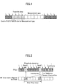
- small gap measurement is proposed.
- the user equipment interrupts communication with a camped base station so as to measure other cells targeted for the inter-frequency measurement and performs preparation operations for the inter-frequency measurement such as adjustment of the RF circuit.
- the user equipment not only performs the inter-frequency measurement but also receives downlink data from the camped base station in subframes sandwiched between the two subframes.
- the first and last two subframes (2 ms) in the measurement gap of 6 ms are preset as the small gap period, and upon receiving a small gap measurement applied inter-frequency measurement indication, the user equipment interrupts communication with the camped base station to prepare the inter-frequency measurement in the small gap period.
- the small gap period may have to be set to be longer than 2 ms due to difference and separation between bandwidths of a camped cell and to-be-measured cell, capability of the RF circuit in the user equipment or the like.
- the inter-frequency measurement period of 4 ms may be also insufficient.
- one object of the present invention is to provide techniques for implementing the inter-frequency measurement with the flexible small gap measurement corresponding to the capability of user equipment and/or the to-be-measured cell.
- one aspect of the present invention relates to user equipment for transmitting and receiving radio signals to/from a base station, comprising: a capability information indication unit configured to indicate capability information of the user equipment to the base station; and an inter-frequency measurement unit configured to perform, upon receiving a small gap measurement applied inter-frequency measurement indication from the base station, a small gap measurement applied inter-frequency measurement in accordance with a small gap period for causing communication with the base station to be interrupted and an inter-frequency measurement period wherein the small gap period and the inter-frequency measurement period correspond to a measurement gap pattern ID indicated in the inter-frequency measurement indication, and measurement gap pattern IDs are predefined each corresponding to small gap periods and inter-frequency measurement periods.
- a base station for transmitting and receiving radio signals to/from user equipment, comprising: a capability information acquisition unit configured to acquire capability information from the user equipment; and an inter-frequency measurement indication unit configured to indicate a small gap measurement applied inter-frequency measurement indication indicative of a measurement gap ID corresponding to a small gap period; and an inter-frequency measurement period to the user equipment based on the capability information acquired from the user equipment wherein measurement gap pattern IDs are predefined each corresponding to small gap periods and inter-frequency measurement periods.
- a still further embodiment of the present invention relates to a method for a base station to indicate inter-frequency measurement to user equipment, comprising: acquiring capability information from the user equipment; determining whether the small gap measurement is applicable based on the capability information acquired from the user equipment; and upon determining that the small gap measurement is applicable, indicating an inter-frequency measurement indication indicative of a measurement gap pattern ID corresponding to a small gap measurement period and an inter-frequency measurement period to the user equipment, wherein measurement gap pattern IDs are predefined each corresponding to small gap periods and inter-frequency measurement periods
- a base station upon receiving capability information from the user equipment, determines whether the small gap measurement applied inter-frequency measurement is allowed in a to-be-measured carrier for the user equipment.
- the capability information includes small gap measurement applicability information indicative of applicability of the small gap measurement in respective carriers supported by the user equipment.
- the capability information may further include a small gap period indicative of a period for causing communication with the base station to be interrupted in the small gap measurement applied inter-frequency measurement for the respective small gap measurement applicable carriers and an inter-frequency measurement period indicative of a period sandwiched between the small gap periods and indicating a period for which the user equipment performs the inter-frequency measurement in receiving downlink data from the base station.
- the user equipment Upon receiving an inter-frequency measurement indication indicating that the small gap measurement with the small gap period and the inter-frequency measurement period should be applied from the base station, the user equipment performs the small gap measurement applied inter-frequency measurement for respective to-be-measured cells in accordance with the small gap period and the inter-frequency measurement period indicated from the base station.
- the inter-frequency measurement with the flexible small gap measurement corresponding to capability of the user equipment and the to-be-measured cells can be implemented compared to the conventional small gap measurement applied inter-frequency measurement where the small gap period and the inter-frequency measurement period are fixed.
- FIG. 3 is a schematic diagram for illustrating a radio communication system according to one embodiment of the present invention.
- a radio communication system 10 has user equipment 100 and base stations 200-202.
- the user equipment 100 uses one or more of cells served by the multiple base stations 200-202 for communication.
- the user equipment 100 is camped in the base station 200.
- the base stations 201, 202 are disposed as adjacent base stations of the base station 200, and if a communication state with the base station 200 is degraded, the user equipment 100 can continue communication by handover to either of the adjacent base stations 201, 202.
- the base station 200 serving a primary cell may configure the cells served by the adjacent base stations 201, 202 as secondary cells for the user equipment 100.
- the user equipment 100 In order to perform the handover and configure a new cell in the carrier aggregation, the user equipment 100 is requested to perform the inter-frequency measurement to measure communication states with the adjacent base stations 201, 202. In the inter-frequency measurement period, an RF circuit is switched into a frequency band different from the cell served by the camped base station 200, and the user equipment 100 cannot communicate with the camped base station 200.
- the user equipment 100 has a small gap measurement function where communication with the base station 200 is interrupted only in the small gap period indicated by the base station 200.
- the user equipment 100 may be any appropriate information processing device with a radio communication function such as a smartphone, a mobile phone, a tablet and a mobile router.
- the user equipment 100 is arranged with a CPU (Central Processing Unit) such as a processor, a memory device such as a RAM (Random Access Memory) and a flash memory, an RF circuit to transmit and receive radio signals to/from the base stations 200-202, or the like.
- a CPU Central Processing Unit
- a memory device such as a RAM (Random Access Memory) and a flash memory
- an RF circuit to transmit and receive radio signals to/from the base stations 200-202, or the like.
- the user equipment 100 Since the RF circuit according to this embodiment is composed of a single chip, the user equipment 100 has to temporarily interrupt communication with a camped cell to perform the inter-frequency measurement. Functions and operations of the user equipment 100 as stated below may be implemented by the CPU processing and running data and programs stored in the memory device. However, the user equipment 100 is not limited to the above-stated hardware configuration and may be arranged with circuits for implementing one or more of operations as stated below.
- the base stations 200-202 establish a radio connection to the user equipment 100 to transmit downlink (DL) packets received from network devices, such as an upper station and a server, communicatively connected on a core network (not shown) to the user equipment 100 as well as transmit uplink (UL) packets received from the user equipment 100 to the network devices.
- the base station 200 serves as a camped base station, and the base stations 201, 202 serve as adjacent base stations. If a communication state with the user equipment 100 is degraded, the base station 200 may indicate handover to the adjacent base stations 201, 202 to the user equipment 100.
- the base station 200 may configure a cell of a different frequency band served by the base station 200 as a secondary cell for the user equipment 100 (intra-carrier aggregation) or configure a cell served by the adjacent base stations 201, 202 as a secondary cell (dual connectivity).
- the base stations 200-202 are typically arranged with hardware resources such as an antenna for transmitting and receiving radio signals to/from the user equipment 100, a communication interface for communicating with the core network, a processor and a circuit for processing signals transmitted and received to/from the user equipment 100 and the core network. Functions and operations of the base stations 200-202 as stated below may be implemented by the processor processing and running data and programs stored in the memory device. However, the base stations 200-202 are not limited to the above-stated hardware configuration and may have any other appropriate hardware configuration.
- FIG. 4 is a block diagram for illustrating an arrangement of the user equipment according to one embodiment of the present invention.
- the user equipment 100 has a capability information indication unit 110 and an inter-frequency measurement unit 120.
- the capability information indication unit 110 indicates capability information of the user equipment 100 to the base station 200.
- the user equipment 100 indicates a frequency band, a bandwidth and various functions such as a carrier aggregation function supported by the user equipment 100 as the capability information to the base station 200.
- the capability information indication unit 110 may indicate small gap measurement applicability information indicative of applicability of small gap measurement in respective to-be-measured carriers and a small gap period for the small gap measurement applicable carriers as the capability information to the base station 200.
- the capability information indication unit 110 prestores the small gap measurement applicability information indicating whether the small gap measurement is applicable in respective carriers or respective frequency bands available to an RF circuit in the user equipment 100 for communication.
- the capability information indication unit 110 would have the small gap measurement applicability information indicating that the small gap measurement is applicable in carriers A and C while the small gap measurement is not applicable in carrier B.
- the capability information indication unit 110 further indicates small gap periods required to perform the small gap measurement applied inter-frequency measurement for the respective small gap measurement applicable carriers A and C.
- the small gap periods are configured to sandwich inter-frequency measurement periods as illustrated and are periods for causing communication with the base station 200 to be interrupted so as to switch the RF circuit from a camped carrier to a carrier targeted for the inter-frequency measurement.
- carrier A needs the small gap period of four subframes (4 ms)
- carrier C needs the small gap period of two subframes (2 ms).
- the capability information indication unit 110 indicates the small gap periods of 4 ms and 2 ms for the small gap measurement applicable carriers A and C, respectively, to the base station 200.
- the capability information indication unit 110 may further indicate the inter-frequency measurement period, where the user equipment 100 can communicate with the base station 200, as the capability information to the base station 200.
- the user equipment 100 temporarily interrupts the communication with the base station 200 for the inter-frequency measurement such as tuning the RF circuit to the carrier targeted for the inter-frequency measurement. After tuning the RF circuit, the user equipment 100 restarts the communication with the base station 200 and performs the inter-frequency measurement in receiving downlink data from the base station 200.
- the inter-frequency measurement period is fixed to a predetermined period such as 4 ms.
- the capability information indication unit 110 may indicate the inter-frequency measurement period for small gap measurement applicable carriers as the capability information to the base station 200 in addition to the small gap measurement applicability information and the small gap period as stated above.
- the inter-frequency measurement period of five subframes (5 ms) is required for carrier A
- the inter-frequency measurement period of four subframes (4 ms) is required for carrier C.
- the capability information indication unit 110 indicates the respective inter-frequency measurement periods of 5 ms and 4 ms for the small gap measurement applicable carriers A and C, respectively, to the base station 200.
- the inter-frequency measurement period is defined as the inter-frequency measurement period in the embodiment, the present invention is not limited to it, and a total period of the small gap period and the period sandwiched by the small gap period may be defined as the inter-frequency measurement period.
- the inter-frequency measurement periods of carriers A and B would be nine subframes (9 ms) and six subframes (6 ms), respectively.
- the capability information indication unit 110 provides the base station 200 with the small gap measurement applicability information as the capability information of the user equipment 100.
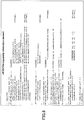
- the capability information indication unit 110 may indicate the capability information including the small gap period and the inter-frequency measurement period to the base station 200 in a data structure as illustrated in FIG. 6 .
- the small gap period may be indicated in the information field "requiredIntrupt-PCell”
- the inter-frequency measurement period may be indicated in the information field "availMeas-sf".
- the capability information indication unit 110 may further indicate the small gap period and the inter-frequency measurement period corresponding to a measurement use type as the capability information to the base station 200.
- the inter-frequency measurement may be performed for different measurement uses such as for performing handover, for configuring a new cell in carrier aggregation, for measuring a configured secondary cell of an inactive state, or the like. Then, it is considered that it may be advantageous to configure the small gap period and the inter-frequency measurement period suitable for the respective measurement uses, and the small gap periods and the inter-frequency measurement periods suitable for the various measurement uses may be predefined.
- the user equipment 100 may store the small gap periods and the inter-frequency measurement periods corresponding to the measurement use types, and the capability information indication unit 110 may indicate the small gap period and the inter-frequency measurement period corresponding to the measurement use type to the base station 200. Then, the base station 200 can indicate the small gap measurement indicative of the small gap period and the inter-frequency measurement period suitable for the measurement use based on the small gap periods and the inter-frequency measurement periods corresponding to the measurement use types.
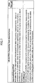
- the capability information indication unit 110 may indicate the small gap period "requiredIntrupt-PCellForIntFreq" and the inter-frequency measurement period "availMeas-sfForIntFreq” for handover measurement and the small gap period "requiredIntrupt-PCellForDeactMeas” and the inter-frequency measurement period "availMeas-sfForDeactMeas” for measurement of secondary cells of an inactive state to the base station 200 in data structures as illustrated in FIGS. 8 and 9 .
- the small gap period and the inter-frequency measurement period may be reported in specific numerical values or be indicated in certain indicators (IDs) associated with certain numerical ranges.
- ID1 may be associated with a small gap measurement pattern "the first half small gap period of 1 ms + the inter-frequency measurement period of 4 ms + the second half small gap period of 1 ms".
- the capability information indication unit 110 may indicate an ID for handover measurement "supportedSgapForInterFreq” and an ID for measurement of a secondary cell of an inactive state "supportedSgapForDeactScell" to the base station 200 in data structures as illustrated in FIGS. 10 and 11 .
- the measurement for handover and the measurement for secondary cells of an inactive state have been exemplified as the measurement use types for the inter-frequency measurement, but is not limited to it, and the small gap period and the inter-frequency measurement period may be configured for any other inter-frequency measurement use. Also, common values may be configured for the small gap period and the inter-frequency measurement period corresponding to the above-stated measurement use type, but is not limited to it, and for example, specific values may be configured for each carrier.
- the inter-frequency measurement unit 120 performs, upon receiving a small gap measurement applied inter-frequency measurement indication from the base station 200, small gap measurement applied inter-frequency measurement in accordance with a small gap period for causing communication with the base station to be interrupted and an inter-frequency measurement period indicated in the inter-frequency measurement indication.
- the inter-frequency measurement indication may be indicated with a measurement gap pattern ID provided corresponding to the indicated small gap period and inter-frequency measurement period.
- the measurement gap pattern ID may be predefined corresponding to the small gap period and the inter-frequency measurement period, and upon receiving the measurement gap pattern ID, the inter-frequency measurement unit 120 may perform the small gap measurement applied inter-frequency measurement with the corresponding small gap period and inter-frequency measurement period.
- the inter-frequency measurement indication may be to perform the small gap measurement applied inter-frequency measurement with the small gap period and the inter-frequency measurement period scheduled by the base station 200 regardless of the measurement gap ID.
- the inter-frequency measurement indication may indicate the small gap period and the inter-frequency measurement period corresponding to the measurement use type.
- the inter-frequency measurement unit 120 Upon receiving the inter-frequency measurement indication, the inter-frequency measurement unit 120 performs the small gap measurement applied inter-frequency measurement for the measurement use with the indicated small gap period and inter-frequency measurement period.
- the inter-frequency measurement unit 120 upon receiving a small gap measurement not-applied inter-frequency measurement indication from the base station 200, performs the inter-frequency measurement corresponding to the indicated measurement gap pattern ID without applying the small gap measurement. Specifically, similar to the conventional inter-frequency measurement, the inter-frequency measurement unit 120 performs the inter-frequency measurement for the whole measurement gap (for example, 6 ms) corresponding to the measurement gap pattern ID.
- the inter-frequency measurement unit 120 may perform the small gap measurement applied inter-frequency measurement for the first carrier or frequency band at the first iteration in iteratively performed measurement gap, the small gap measurement applied inter-frequency measurement for the second carrier or frequency band at the second iteration, and so on.
- Different small gap periods and inter-frequency measurement periods for the multiple carriers may be indicated to the base station 200 as the capability information.
- the base station 200 may indicate the different small gap periods and inter-frequency measurement periods for the respective carriers, it is preferred that the base station 200 indicate common small gap period and inter-frequency measurement period for the respective carriers in order to avoid complication of the inter-frequency measurement.
- Results of the performed inter-frequency measurement are reported to the base station 200 as needed.
- FIG. 12 is a block diagram for illustrating an arrangement of the base station according to one embodiment of the present invention.
- the base station 200 has a capability information acquisition unit 210 and an inter-frequency measurement indication unit 220.
- the capability information acquisition unit 210 acquires capability information, including one or more information elements of small gap measurement applicability information indicative of applicability of small gap measurement in respective to-be-measured carriers, a small gap period for causing communication with the base station 200 to be interrupted in the small gap measurement and an inter-frequency measurement period, from the user equipment 100. Specifically, the capability information acquisition unit 210 may acquire these information elements from the user equipment 100 at timing of connecting to the base station 200 or in response to a request from the base station 200. As stated above, the small gap measurement applicability information indicates whether the small gap measurement is applicable to respective carriers or frequency bands that can be measured by the user equipment 100.
- the small gap period indicates a period for which the communication with the base station 200 is interrupted in the small gap measurement applied inter-frequency measurement, and the inter-frequency measurement period, which is sandwiched between the small gap periods, indicates a period for which the user equipment 100 performs the inter-frequency measurement in receiving downlink data from the base station 200.
- the inter-frequency measurement indication unit 220 indicates a small gap measurement applied inter-frequency measurement indication indicative of the small gap period to the user equipment 100 based on the capability information acquired from the user equipment 100.
- the inter-frequency measurement indication unit 220 may indicate the inter-frequency measurement indication to the user equipment 100 in accordance with any trigger such as degradation of a communication state with the user equipment 100 or in a periodic manner.
- the inter-frequency measurement indication unit 220 determines whether the small gap measurement is applicable to respective to-be-measured carriers based on the acquired small gap measurement applicability information and if the small gap measurement is applicable to all the to-be-measured carriers, indicates an indication to cause the small gap measurement to be applied as well as an inter-frequency measurement indication indicative of the small gap period to the user equipment 100.
- the user equipment 100 can apply the small gap measurement to carriers A and C and cannot apply the small gap measurement to carrier B. Accordingly, if carriers A and C are to be measured, the inter-frequency measurement indication unit 220 may indicate to the user equipment 100 the inter-frequency measurement indication indicating that the small gap measurement should be applied.
- the indication may be fulfilled with the inter-frequency measurement indication including a small gap measurement configuration indication assigned to TRUE.
- the inter-frequency measurement indication unit 220 indicates a small gap measurement not-applied inter-frequency measurement indication to the user equipment 100.
- the indication does not include the small gap measurement configuration indication, and the inter-frequency measurement indication including only the measurement gap pattern ID for identifying a measurement gap may be indicated to the user equipment 100. Also, according to the embodiment in FIG.
- the inter-frequency measurement indication unit 220 may indicate the inter-frequency measurement indication indicative of the small gap period of four subframes (4 ms) to the user equipment 100. Meanwhile, if carrier C is to be measured in the small gap measurement applied inter-frequency measurement, the inter-frequency measurement indication unit 220 may indicate the inter-frequency measurement indication indicative of the small gap period of two subframes (2 ms) to the user equipment 100.
- the inter-frequency measurement indication unit 220 may indicate the small gap measurement applied inter-frequency measurement indication further indicative of an inter-frequency measurement period sandwiched by the small gap period to the user equipment 100.
- the inter-frequency measurement period is fixed to a predetermined period such as 4 ms.
- the inter-frequency measurement period may be also different for different user equipments and/or different to-be-measured carriers, and it is preferred that the inter-frequency measurement period be variably configured corresponding to the user equipment and/or the carrier performing the small gap measurement applied inter-frequency measurement. According to the embodiment in FIG.
- the inter-frequency measurement indication unit 220 may indicate the inter-frequency measurement indication indicative of the inter-frequency measurement period of five subframes (5 ms) to the user equipment 100.
- the inter-frequency measurement indication unit 220 may indicate the inter-frequency measurement indication indicative of the small gap period of four subframes (4 ms).
- the inter-frequency measurement indication unit 220 when the inter-frequency measurement indication unit 220 indicates the small gap measurement applied inter-frequency measurement indication for multiple carriers to the user equipment 100, the inter-frequency measurement indication unit 220 may indicate the small gap period and the inter-frequency measurement period for a carrier having the maximum total period in the total periods of the small gap period and the inter-frequency measurement period for the multiple carriers.
- the inter-frequency measurement indication unit 220 when the small gap measurement applied inter-frequency measurement indication for both carriers A and C is indicated to the user equipment 100, the inter-frequency measurement indication unit 220 indicates the small gap period (4 ms) and the inter-frequency measurement period (5 ms) of carrier A having the longer total period to the user equipment 100.
- the user equipment 100 can apply the common small gap period and inter-frequency measurement period to the inter-frequency measurement in carriers A and C.
- the capability information acquisition unit 210 may acquire the small gap period and the inter-frequency measurement period corresponding to a measurement use type as the capability information from the user equipment 100.
- the inter-frequency measurement indication unit 220 may indicate the inter-frequency measurement indication indicative of the small gap period and the inter-frequency measurement period corresponding to the measurement use to the user equipment 100 based on the small gap period and the inter-frequency measurement period corresponding to the measurement use type acquired from the user equipment 100. For example, it is assumed that the capability information acquisition unit 210 has received the small gap period and the inter-frequency measurement period for handover measurement and the small gap period and the inter-frequency measurement period for measurement of secondary cells of an inactive state.
- the inter-frequency measurement indication unit 220 may indicate to the user equipment 100 the inter-frequency measurement indication indicative of the small gap period and the inter-frequency measurement period for handover measurement reported from the user equipment 100.
- the inter-frequency measurement indication unit 220 may indicate to the user equipment 100 the inter-frequency measurement indication indicative of the small gap period and the inter-frequency measurement period for measurement of secondary cells of the inactive state reported from the user equipment 100. Accordingly, the user equipment 100 can perform the inter-frequency measurement with the small gap period and the inter-frequency measurement period suitable for the measurement use type.
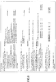
- the inter-frequency measurement indication unit 220 may indicate the inter-frequency measurement indication indicative of the small gap period and the inter-frequency measurement period for handover measurement and the small gap period and the inter-frequency measurement period for measurement of secondary cells of the inactive state to the user equipment 100 in data structures as illustrated in FIGS. 13 and 14 .
- the inter-frequency measurement indication unit 220 may indicate that the small gap period and the inter-frequency measurement period for handover measurement should be applied by configuring respective values for "isgp” in “forInterFreq” in the "sGapOffset” field or indicate that the small gap period and the inter-frequency measurement period for measurement of secondary cells of the inactive state should be applied by configuring respective values for "forDeactSCell" in the field "sGapOffset".
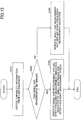
- FIG. 15 is a flowchart for illustrating inter-frequency measurement indication operations in the base station according to one embodiment of the present invention.
- the base station 200 receives capability information from the user equipment 100.
- the capability information includes one or more information elements of small gap measurement applicability information indicative of applicability of small gap measurement in respective to-be-measured carriers, a small gap period for causing communication with the base station 200 to be interrupted in the small gap measurement and an inter-frequency measurement period sandwiched between the small gap periods.
- the base station 200 may acquire the capability information at timing of connecting to the user equipment 100 or the like.
- the base station 200 determines whether the small gap measurement is applicable in the respective to-be-measured carriers based on the small gap measurement applicability information in the received capability information.
- the base station 200 indicates to the user equipment 100 a small gap measurement configuration indication indicating that the small gap measurement should be applied as well as an inter-frequency measurement indication including a small gap period and an inter-frequency measurement period.
- the base station 200 indicates the small gap measurement applied inter-frequency indication indicative of the small gap period and the inter-frequency measurement period acquired for that carrier at step S101.
- the base station 200 determines the small gap period and the inter-frequency measurement period for the carrier having the maximum total period in the total periods of the small gap period and the inter-frequency measurement period for the multiple carriers and indicates the small gap measurement applied inter-frequency measurement indicative of the determined small gap period and inter-frequency measurement period.
- the base station 200 indicates the small gap measurement not-applied inter-frequency measurement to the user equipment 100. Specifically, the base station 200 indicates the inter-frequency measurement indication indicative of a measurement gap ID to the user equipment 100 without including the small gap measurement configuration indication.
- the user equipment 100 After that, the user equipment 100 performs the small gap measurement applied inter-frequency measurement or the small gap measurement not-applied inter-frequency measurement corresponding to the received inter-frequency measurement indication.
- FIG. 16 is a diagram for illustrating exemplary configuration operations of measurement gap configuration according to one embodiment of the present invention.
- the user equipment 100 may configure the inter-frequency measurement in accordance with an ID for handover measurement "supportedSgapPatternForlnterFreq", an ID for measurement of secondary cells of an inactive state "supportedSgapPatternForDeactScell” and "gapOffset” or “sGapOffset” in the reported capability information.
Landscapes
- Engineering & Computer Science (AREA)
- Signal Processing (AREA)
- Computer Networks & Wireless Communication (AREA)
- Databases & Information Systems (AREA)
- Mobile Radio Communication Systems (AREA)
Claims (10)
- Anwenderendgerät (100) zum Senden und Empfangen von Funksignalen zu/von einer Basisstation (200; 201; 202) umfassend:eine Fähigkeitsinformationsanzeigeeinheit (110), die zur Anzeige einer Fähigkeitsinformation des Anwenderendgeräts an die Basisstation konfiguriert ist; unddadurch gekennzeichnet, dass es umfasst:
eine Zwischenfrequenz-Messeinheit (120), die konfiguriert ist, um nach Empfang einer auf Messung kleiner Lücken angewendeten Zwischenfrequenz-Messanzeige von der Basisstation, eine auf Messung kleiner Lücken angewendeten ZwischenfrequenzMessung gemäß einer Periode kleiner Lücken durchzuführen, um zu bewirken, dass eine Kommunikation mit der Basisstation unterbrochen wird, und einer Zwischenfrequenz-Messperiode, wobei die Periode kleiner Lücken und die Zwischenfrequenz-Messperiode einer Messlückenmuster-ID entsprechen, die in der Zwischenfrequenz-Messanzeige angegeben ist, und Messlückenmuster-IDs vordefiniert sind, die jeweils Perioden kleiner Lücken und Zwischenfrequenz-Messperioden entsprechen. - Anwenderendgerät (100) nach Anspruch 1, wobei die Fähigkeitsinformationsanzeigeeinheit (110) konfiguriert ist, um eine Messanwendbarkeitsinformation kleiner Lücken anzuzeigen, die indikativ für die Anwendbarkeit der Messung kleiner Lücken in den jeweiligen zu messenden Trägern ist, und die Periode kleiner Lücken für die Messung anwendbaren Träger kleiner Lücken als die Fähigkeitsinformation der Basisstation (200; 201; 202) anzuzeigen.
- Anwenderendgerät (100) nach Anspruch 1 oder 2, wobei die Fähigkeitsinformationsanzeigeeinheit (110) weiter konfiguriert ist, um die Zwischenfrequenz-Messperiode als die Fähigkeitsinformation an die Basisstation (200; 201; 202) anzuzeigen.
- Anwenderendgerät (100) nach einem der Ansprüche 1 bis 3, wobei die Periode kleiner Lücken konfiguriert ist, um zu bewirken, dass die Zwischenfrequenz-Messperiode eingezwängt angeordnet wird.
- Anwenderendgerät (100) nach einem der Ansprüche 1 bis 4, wobei die Fähigkeitsinformationsanzeigeeinheit (110) weiter konfiguriert ist, um die Periode kleiner Lücken und die Zwischenfrequenz-Messperiode, die einem Messnutzungstyp entsprechen, als die Fähigkeitsinformation an die Basisstation (200; 201; 202) anzuzeigen, wobei die Messnutzung das Durchführen einer Übergabe, das Konfigurieren einer neuen Zelle in einer Trägeraggregation und das Messen einer konfigurierten Sekundärzelle eines inaktiven Zustands umfasst.
- Basisstation (200) zum Senden und Empfangen von Funksignalen zu/von einem Anwenderendgerät (100), umfassend:eine Fähigkeitsinformationserfassungseinheit (210), die zur Erfassung einer Fähigkeitsinformation von dem Anwenderendgerät konfiguriert ist; unddadurch gekennzeichnet, dass sie umfasst: eine Zwischenfrequenz-Messanzeigeeinheit (220), die konfiguriert ist, um eine auf Messung kleiner Lücken angewendete Zwischenfrequenz-Messanzeige, die indikativ für eine Messlücken-ID ist, die einer Periode kleiner Lücken und einer Zwischenfrequenz-Messperiode entspricht, an das Anwenderendgerät anzuzeigen, basierend auf der Fähigkeitsinformation, die von dem Anwenderendgerät erfasst wird, wobei Messlückenmuster-IDs vordefiniert sind, die jeweils Perioden kleiner Lücken und Zwischenfrequenz-Messperioden entsprechen.
- Basisstation (200) nach Anspruch 6, wobei die Zwischenfrequenz-Messanzeigeeinheit (220) konfiguriert ist, um zu bestimmen, ob die Messung kleiner Lücken in den jeweiligen zu messenden Trägern anwendbar ist, basierend auf der erfassten Messanwendbarkeitsinformation kleiner Lücken und wenn die Messung kleiner Lücken in allen zu messenden Trägern anwendbar ist, um eine Anzeige, die bewirkt, dass die Messung kleiner Lücken angewendet wird, sowie eine Zwischenfrequenz-Messanzeige an das Anwenderendgerät anzuzeigen, die indikativ für die Periode kleiner Lücken und die Zwischenfrequenz-Messperiode ist.
- Basisstation (200) nach Anspruch 6 oder 7, wobei die Periode kleiner Lücken konfiguriert ist, um zu bewirken, dass die Zwischenfrequenz-Messperiode eingezwängt angeordnet wird.
- Basisstation (200) nach einem der Ansprüche 6 bis 8, wobei die Fähigkeitsinformationserfassungseinheit (210) konfiguriert ist, um die Periode kleiner Lücken und die Zwischenfrequenz-Messperiode, die einem Messnutzungstyp entsprechen, als die Fähigkeitsinformation von dem Anwenderendgerät (100) zu erfassen, und die Zwischenfrequenzmess-Anzeigeeinheit (220) konfiguriert ist, um eine Zwischenfrequenz-Messanzeige, die indikativ für die Periode kleiner Lücken und die Zwischenfrequenz-Messperiode ist, die dem Messnutzungstyp entsprechen, an das Anwenderendgerät basierend auf der Periode kleiner Lücken und der Zwischenfrequenz-Messperiode, die dem Messnutzungstyp entsprechen, der von dem Anwenderendgerät erfasst wird, anzuzeigen, wobei die Messnutzung das Durchführen einer Übergabe, das Konfigurieren einer neuen Zelle in einer Trägeraggregation und das Messen einer konfigurierten Sekundärzelle eines inaktiven Zustands umfasst.
- Verfahren für eine Basisstation (200), um eine Zwischenfrequenzmessung an ein Anwenderendgerät (100) anzuzeigen, umfassend:Erfassen (S101) einer Fähigkeitsinformation von dem Anwenderendgerät;dadurch gekennzeichnet, dass es umfasst: Bestimmen (S102), ob die Messung kleiner Lücken anwendbar ist, basierend auf der Fähigkeitsinformation, die von dem Anwenderendgerät erfasst wird; undnach dem Bestimmen, dass die Messung kleiner Lücken anwendbar ist, Anzeigen (S103) einer Zwischenfrequenz-Messanzeige an das Anwenderendgerät, die indikativ für eine Messlückenmuster-ID ist, die einer Messperiode kleiner Lücken und einer Zwischenfrequenz-Messperiode entspricht, wobei die Messlückenmuster-IDs vordefiniert sind, die jeweils Perioden kleiner Lücken und Zwischenfrequenz-Messperioden entsprechen.
Applications Claiming Priority (3)
| Application Number | Priority Date | Filing Date | Title |
|---|---|---|---|
| JP2014097362 | 2014-05-09 | ||
| JP2014199399 | 2014-09-29 | ||
| PCT/JP2015/062075 WO2015170579A1 (ja) | 2014-05-09 | 2015-04-21 | ユーザ装置、基地局及び方法 |
Publications (3)
| Publication Number | Publication Date |
|---|---|
| EP3142407A4 EP3142407A4 (de) | 2017-03-15 |
| EP3142407A1 EP3142407A1 (de) | 2017-03-15 |
| EP3142407B1 true EP3142407B1 (de) | 2018-06-20 |
Family
ID=54392432
Family Applications (1)
| Application Number | Title | Priority Date | Filing Date |
|---|---|---|---|
| EP15789951.9A Active EP3142407B1 (de) | 2014-05-09 | 2015-04-21 | Benutzergerät, basisstation und verfahren |
Country Status (4)
| Country | Link |
|---|---|
| US (1) | US10390248B2 (de) |
| EP (1) | EP3142407B1 (de) |
| JP (1) | JP6482538B2 (de) |
| WO (1) | WO2015170579A1 (de) |
Families Citing this family (9)
| Publication number | Priority date | Publication date | Assignee | Title |
|---|---|---|---|---|
| WO2016182527A1 (en) * | 2015-05-14 | 2016-11-17 | Intel IP Corporation | Measurement gap configuration in dual connectivity enhancement |
| US11039330B2 (en) * | 2015-08-12 | 2021-06-15 | Apple Inc. | Method of measurement gap enhancement |
| US11082901B2 (en) | 2016-11-04 | 2021-08-03 | Apple Inc. | Signaling of support for network controlled small gap, NCSG, for interruption control |
| CN110603838A (zh) * | 2017-05-04 | 2019-12-20 | 诺基亚技术有限公司 | 用于带宽受限/覆盖增强的用户设备的无间隙测量 |
| EP3625984B1 (de) * | 2017-05-16 | 2023-05-24 | Apple Inc. | Netzwerkgesteuerte small-gap (ncsg)-signalisierung pro benutzergerät |
| EP3815409A4 (de) | 2018-08-09 | 2022-04-13 | Apple Inc. | Anzeige der benutzergerätekapazität einer empfangsstrahlformung für zellidentifikation |
| WO2021056459A1 (en) * | 2019-09-27 | 2021-04-01 | Nec Corporation | Methods, devices, and medium for communication |
| WO2021161488A1 (ja) * | 2020-02-13 | 2021-08-19 | 株式会社Nttドコモ | 端末及び通信方法 |
| CN113300802B (zh) * | 2020-02-21 | 2022-10-04 | 中国移动通信有限公司研究院 | 传输方法及设备 |
Family Cites Families (7)
| Publication number | Priority date | Publication date | Assignee | Title |
|---|---|---|---|---|
| EP2341730B1 (de) | 2008-09-22 | 2017-11-29 | Sharp Kabushiki Kaisha | Messungen durch ein gerät, das carrier aggregation benutzt |
| CN102448107B (zh) | 2010-09-30 | 2014-11-19 | 华为技术有限公司 | 测量间隙配置方法、终端及网络设备 |
| CN102595475B (zh) * | 2011-01-06 | 2017-12-19 | 中兴通讯股份有限公司 | 一种上报测量能力的方法 |
| US9848340B2 (en) * | 2012-05-18 | 2017-12-19 | Telefonaktiebolaget Lm Ericsson (Publ) | Technique for performing cell measurement on at least two cells |
| KR102010237B1 (ko) * | 2012-07-03 | 2019-08-13 | 삼성전자주식회사 | 디지타이저에서의 좌표 보정 방법 및 장치와 이에 이용되는 전자 펜 |
| US8923880B2 (en) * | 2012-09-28 | 2014-12-30 | Intel Corporation | Selective joinder of user equipment with wireless cell |
| CN105474682A (zh) * | 2013-08-12 | 2016-04-06 | 瑞典爱立信有限公司 | 用于异构网络中的测量的聚簇周期间隙 |
-
2015
- 2015-04-21 US US15/308,250 patent/US10390248B2/en active Active
- 2015-04-21 EP EP15789951.9A patent/EP3142407B1/de active Active
- 2015-04-21 JP JP2016517858A patent/JP6482538B2/ja active Active
- 2015-04-21 WO PCT/JP2015/062075 patent/WO2015170579A1/ja active Application Filing
Non-Patent Citations (1)
| Title |
|---|
| None * |
Also Published As
| Publication number | Publication date |
|---|---|
| WO2015170579A1 (ja) | 2015-11-12 |
| JPWO2015170579A1 (ja) | 2017-04-20 |
| JP6482538B2 (ja) | 2019-03-13 |
| EP3142407A4 (de) | 2017-03-15 |
| US20170064578A1 (en) | 2017-03-02 |
| US10390248B2 (en) | 2019-08-20 |
| EP3142407A1 (de) | 2017-03-15 |
Similar Documents
| Publication | Publication Date | Title |
|---|---|---|
| EP3142407B1 (de) | Benutzergerät, basisstation und verfahren | |
| US10484983B2 (en) | Robust control channel transmission scheme | |
| EP3206448B1 (de) | Verfahren und vorrichtung zur konfiguration einer zelle in einem drahtloskommunikationssystem | |
| CN109076373B (zh) | 基于lbt参数控制测量的方法 | |
| EP3190827A1 (de) | Basisstation und benutzervorrichtung | |
| US20190223216A1 (en) | Systems and methods for controlling ue inter-frequency measurements in gaps in presence of lbt | |
| US10945156B2 (en) | User equipment that controls broadcast information and base station that controls broadcast information | |
| EP3791618B1 (de) | Funkverbindungsüberwachungsverfahren (rlm) für eine drahtlose vorrichtung, die so konfiguriert ist, dass sie mit einem ersten und einem zweiten betriebsmodus innerhalb einer überlappungszeit in einer ersten zelle arbeitet | |
| WO2018025070A1 (en) | 5g beam group discontinuous reception | |
| US10153882B2 (en) | User equipment and capability reporting method | |
| CN108810944B (zh) | 上行载波切换的方法、网络设备和终端设备 | |
| CN111386741B (zh) | 一种链路恢复方法、终端设备及网络设备 | |
| US11202219B2 (en) | Two-level mobility reference signal configuration | |
| EP3530054A1 (de) | Direktzugriff für nr | |
| CN109287000A (zh) | 在双连接中设定次要节点及回报的装置及方法 | |
| US11770696B2 (en) | UE capability signaling for supporting reference signal based measurements in 5G new radio unlicensed spectrum (NR-U) | |
| US20230388779A1 (en) | Ue capability signaling for supporting reference signal based measurements in 5g new radio unlicensed spectrum (nr-u) | |
| CN109362088B (zh) | Gsm的从模信息的测量方法和装置 | |
| CN115836489A (zh) | 装置、方法和计算机程序 | |
| JP2015186034A (ja) | ユーザ装置、基地局及び方法 | |
| WO2017081360A1 (en) | Multi-connectivity of terminal device in cellular system | |
| US20220210833A1 (en) | Channel detection before transmission | |
| KR20240049336A (ko) | 통신 방법 및 통신 장치 | |
| CN115699851A (zh) | Csi-rs测量的优化 |
Legal Events
| Date | Code | Title | Description |
|---|---|---|---|
| STAA | Information on the status of an ep patent application or granted ep patent |
Free format text: STATUS: THE INTERNATIONAL PUBLICATION HAS BEEN MADE |
|
| PUAI | Public reference made under article 153(3) epc to a published international application that has entered the european phase |
Free format text: ORIGINAL CODE: 0009012 |
|
| STAA | Information on the status of an ep patent application or granted ep patent |
Free format text: STATUS: REQUEST FOR EXAMINATION WAS MADE |
|
| 17P | Request for examination filed |
Effective date: 20160930 |
|
| A4 | Supplementary search report drawn up and despatched |
Effective date: 20170214 |
|
| AK | Designated contracting states |
Kind code of ref document: A1 Designated state(s): AL AT BE BG CH CY CZ DE DK EE ES FI FR GB GR HR HU IE IS IT LI LT LU LV MC MK MT NL NO PL PT RO RS SE SI SK SM TR |
|
| AX | Request for extension of the european patent |
Extension state: BA ME |
|
| DAV | Request for validation of the european patent (deleted) | ||
| DAX | Request for extension of the european patent (deleted) | ||
| REG | Reference to a national code |
Ref country code: DE Ref legal event code: R079 Ref document number: 602015012600 Country of ref document: DE Free format text: PREVIOUS MAIN CLASS: H04W0024100000 Ipc: H04W0036000000 |
|
| GRAP | Despatch of communication of intention to grant a patent |
Free format text: ORIGINAL CODE: EPIDOSNIGR1 |
|
| STAA | Information on the status of an ep patent application or granted ep patent |
Free format text: STATUS: GRANT OF PATENT IS INTENDED |
|
| RIC1 | Information provided on ipc code assigned before grant |
Ipc: H04W 36/00 20090101AFI20171220BHEP Ipc: H04W 8/22 20090101ALN20171220BHEP Ipc: H04W 24/00 20090101ALN20171220BHEP |
|
| INTG | Intention to grant announced |
Effective date: 20180109 |
|
| GRAS | Grant fee paid |
Free format text: ORIGINAL CODE: EPIDOSNIGR3 |
|
| GRAA | (expected) grant |
Free format text: ORIGINAL CODE: 0009210 |
|
| STAA | Information on the status of an ep patent application or granted ep patent |
Free format text: STATUS: THE PATENT HAS BEEN GRANTED |
|
| AK | Designated contracting states |
Kind code of ref document: B1 Designated state(s): AL AT BE BG CH CY CZ DE DK EE ES FI FR GB GR HR HU IE IS IT LI LT LU LV MC MK MT NL NO PL PT RO RS SE SI SK SM TR |
|
| REG | Reference to a national code |
Ref country code: GB Ref legal event code: FG4D |
|
| REG | Reference to a national code |
Ref country code: IE Ref legal event code: FG4D |
|
| REG | Reference to a national code |
Ref country code: AT Ref legal event code: REF Ref document number: 1011433 Country of ref document: AT Kind code of ref document: T Effective date: 20180715 |
|
| REG | Reference to a national code |
Ref country code: DE Ref legal event code: R096 Ref document number: 602015012600 Country of ref document: DE |
|
| REG | Reference to a national code |
Ref country code: SE Ref legal event code: TRGR |
|
| REG | Reference to a national code |
Ref country code: NL Ref legal event code: MP Effective date: 20180620 |
|
| PG25 | Lapsed in a contracting state [announced via postgrant information from national office to epo] |
Ref country code: FI Free format text: LAPSE BECAUSE OF FAILURE TO SUBMIT A TRANSLATION OF THE DESCRIPTION OR TO PAY THE FEE WITHIN THE PRESCRIBED TIME-LIMIT Effective date: 20180620 Ref country code: BG Free format text: LAPSE BECAUSE OF FAILURE TO SUBMIT A TRANSLATION OF THE DESCRIPTION OR TO PAY THE FEE WITHIN THE PRESCRIBED TIME-LIMIT Effective date: 20180920 Ref country code: NO Free format text: LAPSE BECAUSE OF FAILURE TO SUBMIT A TRANSLATION OF THE DESCRIPTION OR TO PAY THE FEE WITHIN THE PRESCRIBED TIME-LIMIT Effective date: 20180920 Ref country code: LT Free format text: LAPSE BECAUSE OF FAILURE TO SUBMIT A TRANSLATION OF THE DESCRIPTION OR TO PAY THE FEE WITHIN THE PRESCRIBED TIME-LIMIT Effective date: 20180620 |
|
| REG | Reference to a national code |
Ref country code: LT Ref legal event code: MG4D |
|
| PG25 | Lapsed in a contracting state [announced via postgrant information from national office to epo] |
Ref country code: GR Free format text: LAPSE BECAUSE OF FAILURE TO SUBMIT A TRANSLATION OF THE DESCRIPTION OR TO PAY THE FEE WITHIN THE PRESCRIBED TIME-LIMIT Effective date: 20180921 Ref country code: HR Free format text: LAPSE BECAUSE OF FAILURE TO SUBMIT A TRANSLATION OF THE DESCRIPTION OR TO PAY THE FEE WITHIN THE PRESCRIBED TIME-LIMIT Effective date: 20180620 Ref country code: RS Free format text: LAPSE BECAUSE OF FAILURE TO SUBMIT A TRANSLATION OF THE DESCRIPTION OR TO PAY THE FEE WITHIN THE PRESCRIBED TIME-LIMIT Effective date: 20180620 Ref country code: LV Free format text: LAPSE BECAUSE OF FAILURE TO SUBMIT A TRANSLATION OF THE DESCRIPTION OR TO PAY THE FEE WITHIN THE PRESCRIBED TIME-LIMIT Effective date: 20180620 |
|
| REG | Reference to a national code |
Ref country code: AT Ref legal event code: MK05 Ref document number: 1011433 Country of ref document: AT Kind code of ref document: T Effective date: 20180620 |
|
| PG25 | Lapsed in a contracting state [announced via postgrant information from national office to epo] |
Ref country code: NL Free format text: LAPSE BECAUSE OF FAILURE TO SUBMIT A TRANSLATION OF THE DESCRIPTION OR TO PAY THE FEE WITHIN THE PRESCRIBED TIME-LIMIT Effective date: 20180620 |
|
| PG25 | Lapsed in a contracting state [announced via postgrant information from national office to epo] |
Ref country code: AT Free format text: LAPSE BECAUSE OF FAILURE TO SUBMIT A TRANSLATION OF THE DESCRIPTION OR TO PAY THE FEE WITHIN THE PRESCRIBED TIME-LIMIT Effective date: 20180620 Ref country code: RO Free format text: LAPSE BECAUSE OF FAILURE TO SUBMIT A TRANSLATION OF THE DESCRIPTION OR TO PAY THE FEE WITHIN THE PRESCRIBED TIME-LIMIT Effective date: 20180620 Ref country code: CZ Free format text: LAPSE BECAUSE OF FAILURE TO SUBMIT A TRANSLATION OF THE DESCRIPTION OR TO PAY THE FEE WITHIN THE PRESCRIBED TIME-LIMIT Effective date: 20180620 Ref country code: PL Free format text: LAPSE BECAUSE OF FAILURE TO SUBMIT A TRANSLATION OF THE DESCRIPTION OR TO PAY THE FEE WITHIN THE PRESCRIBED TIME-LIMIT Effective date: 20180620 Ref country code: IS Free format text: LAPSE BECAUSE OF FAILURE TO SUBMIT A TRANSLATION OF THE DESCRIPTION OR TO PAY THE FEE WITHIN THE PRESCRIBED TIME-LIMIT Effective date: 20181020 Ref country code: EE Free format text: LAPSE BECAUSE OF FAILURE TO SUBMIT A TRANSLATION OF THE DESCRIPTION OR TO PAY THE FEE WITHIN THE PRESCRIBED TIME-LIMIT Effective date: 20180620 Ref country code: SK Free format text: LAPSE BECAUSE OF FAILURE TO SUBMIT A TRANSLATION OF THE DESCRIPTION OR TO PAY THE FEE WITHIN THE PRESCRIBED TIME-LIMIT Effective date: 20180620 |
|
| PG25 | Lapsed in a contracting state [announced via postgrant information from national office to epo] |
Ref country code: ES Free format text: LAPSE BECAUSE OF FAILURE TO SUBMIT A TRANSLATION OF THE DESCRIPTION OR TO PAY THE FEE WITHIN THE PRESCRIBED TIME-LIMIT Effective date: 20180620 Ref country code: IT Free format text: LAPSE BECAUSE OF FAILURE TO SUBMIT A TRANSLATION OF THE DESCRIPTION OR TO PAY THE FEE WITHIN THE PRESCRIBED TIME-LIMIT Effective date: 20180620 Ref country code: SM Free format text: LAPSE BECAUSE OF FAILURE TO SUBMIT A TRANSLATION OF THE DESCRIPTION OR TO PAY THE FEE WITHIN THE PRESCRIBED TIME-LIMIT Effective date: 20180620 |
|
| REG | Reference to a national code |
Ref country code: DE Ref legal event code: R097 Ref document number: 602015012600 Country of ref document: DE |
|
| PLBE | No opposition filed within time limit |
Free format text: ORIGINAL CODE: 0009261 |
|
| STAA | Information on the status of an ep patent application or granted ep patent |
Free format text: STATUS: NO OPPOSITION FILED WITHIN TIME LIMIT |
|
| 26N | No opposition filed |
Effective date: 20190321 |
|
| PG25 | Lapsed in a contracting state [announced via postgrant information from national office to epo] |
Ref country code: DK Free format text: LAPSE BECAUSE OF FAILURE TO SUBMIT A TRANSLATION OF THE DESCRIPTION OR TO PAY THE FEE WITHIN THE PRESCRIBED TIME-LIMIT Effective date: 20180620 |
|
| PG25 | Lapsed in a contracting state [announced via postgrant information from national office to epo] |
Ref country code: SI Free format text: LAPSE BECAUSE OF FAILURE TO SUBMIT A TRANSLATION OF THE DESCRIPTION OR TO PAY THE FEE WITHIN THE PRESCRIBED TIME-LIMIT Effective date: 20180620 |
|
| PG25 | Lapsed in a contracting state [announced via postgrant information from national office to epo] |
Ref country code: AL Free format text: LAPSE BECAUSE OF FAILURE TO SUBMIT A TRANSLATION OF THE DESCRIPTION OR TO PAY THE FEE WITHIN THE PRESCRIBED TIME-LIMIT Effective date: 20180620 |
|
| REG | Reference to a national code |
Ref country code: BE Ref legal event code: MM Effective date: 20190430 |
|
| PG25 | Lapsed in a contracting state [announced via postgrant information from national office to epo] |
Ref country code: MC Free format text: LAPSE BECAUSE OF FAILURE TO SUBMIT A TRANSLATION OF THE DESCRIPTION OR TO PAY THE FEE WITHIN THE PRESCRIBED TIME-LIMIT Effective date: 20180620 Ref country code: LU Free format text: LAPSE BECAUSE OF NON-PAYMENT OF DUE FEES Effective date: 20190421 |
|
| PG25 | Lapsed in a contracting state [announced via postgrant information from national office to epo] |
Ref country code: FR Free format text: LAPSE BECAUSE OF NON-PAYMENT OF DUE FEES Effective date: 20190430 Ref country code: BE Free format text: LAPSE BECAUSE OF NON-PAYMENT OF DUE FEES Effective date: 20190430 |
|
| PG25 | Lapsed in a contracting state [announced via postgrant information from national office to epo] |
Ref country code: TR Free format text: LAPSE BECAUSE OF FAILURE TO SUBMIT A TRANSLATION OF THE DESCRIPTION OR TO PAY THE FEE WITHIN THE PRESCRIBED TIME-LIMIT Effective date: 20180620 |
|
| PG25 | Lapsed in a contracting state [announced via postgrant information from national office to epo] |
Ref country code: IE Free format text: LAPSE BECAUSE OF NON-PAYMENT OF DUE FEES Effective date: 20190421 |
|
| PG25 | Lapsed in a contracting state [announced via postgrant information from national office to epo] |
Ref country code: PT Free format text: LAPSE BECAUSE OF FAILURE TO SUBMIT A TRANSLATION OF THE DESCRIPTION OR TO PAY THE FEE WITHIN THE PRESCRIBED TIME-LIMIT Effective date: 20181022 |
|
| PG25 | Lapsed in a contracting state [announced via postgrant information from national office to epo] |
Ref country code: CY Free format text: LAPSE BECAUSE OF FAILURE TO SUBMIT A TRANSLATION OF THE DESCRIPTION OR TO PAY THE FEE WITHIN THE PRESCRIBED TIME-LIMIT Effective date: 20180620 |
|
| PG25 | Lapsed in a contracting state [announced via postgrant information from national office to epo] |
Ref country code: MT Free format text: LAPSE BECAUSE OF FAILURE TO SUBMIT A TRANSLATION OF THE DESCRIPTION OR TO PAY THE FEE WITHIN THE PRESCRIBED TIME-LIMIT Effective date: 20180620 Ref country code: HU Free format text: LAPSE BECAUSE OF FAILURE TO SUBMIT A TRANSLATION OF THE DESCRIPTION OR TO PAY THE FEE WITHIN THE PRESCRIBED TIME-LIMIT; INVALID AB INITIO Effective date: 20150421 |
|
| PG25 | Lapsed in a contracting state [announced via postgrant information from national office to epo] |
Ref country code: MK Free format text: LAPSE BECAUSE OF FAILURE TO SUBMIT A TRANSLATION OF THE DESCRIPTION OR TO PAY THE FEE WITHIN THE PRESCRIBED TIME-LIMIT Effective date: 20180620 |
|
| P01 | Opt-out of the competence of the unified patent court (upc) registered |
Effective date: 20230509 |
|
| PGFP | Annual fee paid to national office [announced via postgrant information from national office to epo] |
Ref country code: DE Payment date: 20230420 Year of fee payment: 9 Ref country code: CH Payment date: 20230502 Year of fee payment: 9 |
|
| PGFP | Annual fee paid to national office [announced via postgrant information from national office to epo] |
Ref country code: SE Payment date: 20230420 Year of fee payment: 9 |
|
| PGFP | Annual fee paid to national office [announced via postgrant information from national office to epo] |
Ref country code: GB Payment date: 20230419 Year of fee payment: 9 |