EP3142366A1 - Procédé et appareil de codage et de décodage d'une image basée sur un champ de lumière et produit programme d'ordinateur correspondant - Google Patents
Procédé et appareil de codage et de décodage d'une image basée sur un champ de lumière et produit programme d'ordinateur correspondant Download PDFInfo
- Publication number
- EP3142366A1 EP3142366A1 EP15306409.2A EP15306409A EP3142366A1 EP 3142366 A1 EP3142366 A1 EP 3142366A1 EP 15306409 A EP15306409 A EP 15306409A EP 3142366 A1 EP3142366 A1 EP 3142366A1
- Authority
- EP
- European Patent Office
- Prior art keywords
- pixels
- predict
- pixel
- block
- epipolar plane
- Prior art date
- Legal status (The legal status is an assumption and is not a legal conclusion. Google has not performed a legal analysis and makes no representation as to the accuracy of the status listed.)
- Withdrawn
Links
Images

Classifications
-
- H—ELECTRICITY
- H04—ELECTRIC COMMUNICATION TECHNIQUE
- H04N—PICTORIAL COMMUNICATION, e.g. TELEVISION
- H04N19/00—Methods or arrangements for coding, decoding, compressing or decompressing digital video signals
- H04N19/10—Methods or arrangements for coding, decoding, compressing or decompressing digital video signals using adaptive coding
- H04N19/102—Methods or arrangements for coding, decoding, compressing or decompressing digital video signals using adaptive coding characterised by the element, parameter or selection affected or controlled by the adaptive coding
- H04N19/103—Selection of coding mode or of prediction mode
-
- H—ELECTRICITY
- H04—ELECTRIC COMMUNICATION TECHNIQUE
- H04N—PICTORIAL COMMUNICATION, e.g. TELEVISION
- H04N19/00—Methods or arrangements for coding, decoding, compressing or decompressing digital video signals
- H04N19/10—Methods or arrangements for coding, decoding, compressing or decompressing digital video signals using adaptive coding
- H04N19/134—Methods or arrangements for coding, decoding, compressing or decompressing digital video signals using adaptive coding characterised by the element, parameter or criterion affecting or controlling the adaptive coding
- H04N19/146—Data rate or code amount at the encoder output
- H04N19/15—Data rate or code amount at the encoder output by monitoring actual compressed data size at the memory before deciding storage at the transmission buffer
-
- H—ELECTRICITY
- H04—ELECTRIC COMMUNICATION TECHNIQUE
- H04N—PICTORIAL COMMUNICATION, e.g. TELEVISION
- H04N19/00—Methods or arrangements for coding, decoding, compressing or decompressing digital video signals
- H04N19/10—Methods or arrangements for coding, decoding, compressing or decompressing digital video signals using adaptive coding
- H04N19/169—Methods or arrangements for coding, decoding, compressing or decompressing digital video signals using adaptive coding characterised by the coding unit, i.e. the structural portion or semantic portion of the video signal being the object or the subject of the adaptive coding
- H04N19/17—Methods or arrangements for coding, decoding, compressing or decompressing digital video signals using adaptive coding characterised by the coding unit, i.e. the structural portion or semantic portion of the video signal being the object or the subject of the adaptive coding the unit being an image region, e.g. an object
- H04N19/172—Methods or arrangements for coding, decoding, compressing or decompressing digital video signals using adaptive coding characterised by the coding unit, i.e. the structural portion or semantic portion of the video signal being the object or the subject of the adaptive coding the unit being an image region, e.g. an object the region being a picture, frame or field
-
- H—ELECTRICITY
- H04—ELECTRIC COMMUNICATION TECHNIQUE
- H04N—PICTORIAL COMMUNICATION, e.g. TELEVISION
- H04N19/00—Methods or arrangements for coding, decoding, compressing or decompressing digital video signals
- H04N19/10—Methods or arrangements for coding, decoding, compressing or decompressing digital video signals using adaptive coding
- H04N19/169—Methods or arrangements for coding, decoding, compressing or decompressing digital video signals using adaptive coding characterised by the coding unit, i.e. the structural portion or semantic portion of the video signal being the object or the subject of the adaptive coding
- H04N19/182—Methods or arrangements for coding, decoding, compressing or decompressing digital video signals using adaptive coding characterised by the coding unit, i.e. the structural portion or semantic portion of the video signal being the object or the subject of the adaptive coding the unit being a pixel
-
- H—ELECTRICITY
- H04—ELECTRIC COMMUNICATION TECHNIQUE
- H04N—PICTORIAL COMMUNICATION, e.g. TELEVISION
- H04N19/00—Methods or arrangements for coding, decoding, compressing or decompressing digital video signals
- H04N19/50—Methods or arrangements for coding, decoding, compressing or decompressing digital video signals using predictive coding
- H04N19/503—Methods or arrangements for coding, decoding, compressing or decompressing digital video signals using predictive coding involving temporal prediction
- H04N19/51—Motion estimation or motion compensation
- H04N19/577—Motion compensation with bidirectional frame interpolation, i.e. using B-pictures
-
- H—ELECTRICITY
- H04—ELECTRIC COMMUNICATION TECHNIQUE
- H04N—PICTORIAL COMMUNICATION, e.g. TELEVISION
- H04N19/00—Methods or arrangements for coding, decoding, compressing or decompressing digital video signals
- H04N19/50—Methods or arrangements for coding, decoding, compressing or decompressing digital video signals using predictive coding
- H04N19/597—Methods or arrangements for coding, decoding, compressing or decompressing digital video signals using predictive coding specially adapted for multi-view video sequence encoding
-
- H—ELECTRICITY
- H04—ELECTRIC COMMUNICATION TECHNIQUE
- H04N—PICTORIAL COMMUNICATION, e.g. TELEVISION
- H04N19/00—Methods or arrangements for coding, decoding, compressing or decompressing digital video signals
- H04N19/80—Details of filtering operations specially adapted for video compression, e.g. for pixel interpolation
Definitions
- the present disclosure relates to light field imaging, and to technologies for acquiring and processing light field data. More precisely, the present disclosure generally relates to a method and an apparatus for encoding and decoding a light field based image, and finds applications in the domain of image or video encoding/decoding.
- Conventional image capture devices render a three-dimensional scene onto a two-dimensional sensor.
- a conventional capture device captures a two-dimensional (2-D) image representing an amount of light that reaches a photosensor (or photodetector) within the device.
- this 2-D image contains no information about the directional distribution of the light rays that reach the photosensor (which may be referred to as the light field). Depth, for example, is lost during the acquisition. Thus, a conventional capture device does not store most of the information about the light distribution from the scene.
- Light field capture devices (also referred to as “light field data acquisition devices”) have been designed to measure a four-dimensional (4D) light field of the scene by capturing the light from different viewpoints of that scene. Thus, by measuring the amount of light traveling along each beam of light that intersects the photosensor, these devices can capture additional optical information (information about the directional distribution of the bundle of light rays) for providing new imaging applications by post-processing.
- the information acquired/obtained by a light field capture device is referred to as the light field data.
- Light field capture devices are defined herein as any devices that are capable of capturing light field data. There are several types of light field capture devices, among which:
- the light field data may also be simulated with Computer Generated Imagery (CGI), from a series of 2-D images of a scene each taken from a different viewpoint by the use of a conventional handheld camera.
- CGI Computer Generated Imagery
- Light field data processing comprises notably, but is not limited to, generating refocused images of a scene, generating perspective views of a scene, generating depth maps of a scene, generating extended depth of field (EDOF) images, generating stereoscopic images, and/or any combination of these.
- EEOF extended depth of field
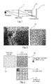
- the present disclosure focuses more precisely on light field based image captured by a plenoptic device as illustrated by Fig. 1 disclosed by R. Ng, et al. in "Light field photography with a hand-held plenoptic camera” Standford University Computer Science Technical Report CSTR 2005-02, no. 11 (April 2005 ).
- Such plenoptic device is composed of a main lens (11), a micro-lens array (12) and a photo-sensor (13). More precisely, the men lens focuses the subject onto (or near) the micro-lens array.
- the micro-lens array (12) separates the converging rays into an image on the photo-sensor (13) behind it.
- a micro-image is the image (14) formed on the photo-sensor behind a considered micro-lens of the micro-lens array (12) as illustrated by Fig. 2 disclosed by http://www.tgeorgiev.net/ where the image on the left corresponds to raw data and the image on the right corresponds to details of micro-images representing in particular a seagull's head.
- Micro-images resolution and number depend on micro-lenses size with respect to the sensor. More precisely, the micro-image resolution varies significantly depending on devices and applications (from 2x2 pixels up to around 100x100 pixels).
- the NxN matrix of views (17) is obtained by considering that the i th view contains all the LxL i th pixels overlapped by each micro-lens of the micro-lens array (16) comprising LxL micro-lenses, where "x" is a multiplication operator.
- the first view 300 will thus comprises the first of the sixteen pixels covered by each micro-lens of the 64 micro-lenses of the considered micro-lens array.
- camera array devices such as the Pelican Imaging ® camera, deliver directly matrices of views (i.e. without de-mozaicing).
- the disclosure sets out to remedy at least one of the drawbacks of the prior art with a method for predicting at least one block of pixels of a view belonging to a matrix of views obtained from light-field data associated with a scene.
- Such method is implemented by a processor and comprises for at least one pixel to predict of said block of pixels:
- the present disclosure thus relies on a novel and inventive approach for predicting at least one block of pixels of a view belonging to a matrix of views obtained from light-field data associated with a scene.
- the present disclosure benefits from the specific properties of the linear structures inside an epipolar plane image.
- a horizontal (respectively a vertical) epipolar plane image is a 2D image, built by stacking all images of a matrix of views along a line (respectively a column) of views of said matrix of view, on top of each other, and corresponds to a cut through the obtained stack along a same line of each stacked view (respectively along a same column of each stacked view).
- said at least one epipolar plane image is a horizontal epipolar plane image (EPI), a vertical epipolar plane image (EPI) or an epipolar plane image (EPI) presenting an angular orientation with respect to a horizontal or vertical epipolar plane image (said angular orientation being predetermined or not).
- Determining at least one optimal unidirectional prediction mode, among a set of unidirectional prediction modes (predetermined or not), from a set of previous reconstructed pixels neighbouring said at least one pixel to predict in said at least one epipolar plane image permits to take advantage of the inter-views correlations accurately, i.e. with a pixel (or a group of pixels smaller than a block of pixels) resolution, which is not possible according to the predicting methods of the prior art such as the one of the H.264 standard.
- the predicting mode of the present disclosure based on the Epipolar Plane images, it is possible to provide a prediction mode, which is more optimal with respect to the specificities of plenoptic imaging providing matrix of views.
- epipolar plane images permits to exploit the properties of the four-dimensional (4D) light field of the scene, since their building is based on the stacking of views representing the light from different viewpoints of that scene, i.e. viewpoints of a same line of the matrix of views for a horizontal epipolar plane image, of a same column of the matrix of views for a vertical epipolar plane image, or of a same set of views of said matrix of views presenting an angular orientation with respect to a line or a column of said matrix of views.
- said determining said optimal unidirectional prediction mode comprises, for at least one pixel to predict of said block of pixels:
- each unidirectional prediction mode is associated with a direction of extrapolation of the prediction value of said at least one pixel to predict from a set of previous reconstructed pixels neighbouring said at least one pixel to predict in said at least one epipolar plane image.
- the selected optimal unidirectional prediction mode corresponds to the unidirectional prediction mode, which is the most adapted with respect to the directional structure of the considered epipolar plane image used for the pixel to predict of the considered block of pixels.
- the method for predicting of the present disclosure further comprises providing at least one group of pixels to predict within said block of pixels, said group of pixels comprising at least two pixels of a same line, of a same column, or of a set of at least two pixels presenting an angular orientation with respect to a line or a column of said block of pixels, wherein determining said optimal unidirectional prediction mode comprises:
- the implemented selection is robust since a single optimal unidirectional prediction mode is obtained for all pixels to predict belonging to said group, such optimal unidirectional prediction mode presenting the energy level, which is the argument of the minimum of energy levels obtained for each unidirectional prediction mode and for at least one pixel to predict of said group of pixels.
- the selection is done by taking into account more obtained energy levels than the ones taken into account in the previous embodiment, where the selection of the optimal unidirectional prediction mode is performed so that an optimal unidirectional prediction mode is obtained per pixel to predict and not for all pixels to predict belonging to said group of pixels.
- EPI epipolar plane images
- EPI horizontal epipolar plane image
- EPI vertical epipolar plane image
- EPI a set of different angular orientations epipolar plane images
- determining said optimal unidirectional prediction mode is performed for said horizontal epipolar plane image (EPI) and for said vertical epipolar plane image (EPI), or for a set of different angular orientations epipolar plane images (EPI)
- said optimal unidirectional prediction mode corresponding to the unidirectional prediction mode of which the energy level is the argument of the minimum of energy levels obtained for each epipolar plane image.
- an optimal unidirectional prediction mode is determined for each epipolar plane image and said prediction value of said at least one pixel to predict corresponds to a mean of at least two prediction values obtained respectively by using said optimal unidirectional prediction mode determined for each epipolar plane image.
- associating a different filtering operation with each unidirectional prediction mode of said set of unidirectional prediction modes comprises, for each different filtering operation, locating an application point among said set of previous reconstructed pixels neighbouring said at least one pixel to predict in said at least one epipolar plane image.
- Such an aspect increase the accuracy of the following step of applying each filtering operation to said set of previous reconstructed pixels neighbouring said pixel to predict in said at least one epipolar plane image, to obtain an energy level for each unidirectional prediction mode.
- one of the unidirectional prediction modes corresponds to the unidirectional prediction mode of which the extrapolating direction is the direction from said at least one reconstructed pixel, belonging both to said at least one epipolar plane image and to said view, to said pixel to predict.
- the invention also relates to a method for encoding at least one block of pixels of a view belonging to a matrix of views obtained from light-field data associated with a scene.
- Such method is implemented by a processor and comprises:
- the prediction implemented during said encoding could of course comprise the different features of the predicting method according to the different embodiments or variants of the present disclosure as previously described.
- said method for encoding further comprises:
- Another aspect of the present disclosure pertains to a signal representing at least one block of pixels of a matrix of views obtained from light-field data associated with said scene, said signal being obtained by said method for encoding as described above wherein information representing at least one group of pixels to predict within said block of pixels is inserted in said signal.
- Another aspect of the present disclosure concerns a recording medium bearing a signal as described above.
- Another aspect of the present disclosure pertains to a method for decoding a signal representing at least one block of pixels of a view belonging to a matrix of views obtained from light-field data associated with a scene.
- Such method is implemented by a processor and comprises:
- Such a method for decoding is especially suited to decode a signal encoded according to the above-described encoding method.
- the same prediction steps are performed as those performed when encoding so as to rebuilt the given block of pixels, and by optionally adding the prediction residue (transmitted in the signal) to the prediction.
- Another aspect of the present disclosure pertains to a device for encoding at least one block of pixels of a view belonging to a matrix of views obtained from light-field data associated with a scene, wherein said device comprises a processor configured to control:
- Such an encoding device is adapted especially for implementing the method for encoding as described here above.
- Another aspect of the present disclosure pertains to a device for decoding a signal representing at least one block of pixels of a view belonging to a matrix of views obtained from light-field data associated with a scene, wherein said device comprises a processor configured to control:
- Such a decoding device is adapted especially for implementing the method for decoding as described here above.
- the disclosure relates thus to devices comprising a processor configured to implement the above methods.
- the disclosure relates to a computer program product comprising program code instructions to execute the steps of the above methods when this program is executed on a computer, a processor readable medium having stored therein instructions for causing a processor to perform at least the steps of the above methods, and a non-transitory storage medium carrying instructions of program code for executing steps of the above methods when said program is executed on a computing device.
- the present disclosure proposes a new technique for encoding (or decoding) an image of matrix of views implementing a new type of prediction based on the Epipolar Plane Images (EPI) representation of a matrix of views.
- EPI Epipolar Plane Images
- the approach proposed in the present disclosure is thus able to cope with the specific properties of the linear structures inside the Epipolar Plane Images (EPI) and as a consequence suitable for exploiting the properties of the four-dimensional (4D) light field of the scene.
- EPI Epipolar Plane Images
- each block represents a circuit element, module, or portion of code which comprises one or more executable instructions for implementing the specified logical function(s).
- the function(s) noted in the blocks may occur out of the order noted. For example, two blocks shown in succession may, in fact, be executed substantially concurrently or the blocks may sometimes be executed in the reverse order, depending on the functionality involved.
- the disclosure is described for encoding/decoding a block of pixels of a view of a matrix of views but extends to the encoding/decoding of a sequence of matrix of views (plenoptic video) because each view of each matrix of views belonging to said sequence is sequentially encoded/decoded as described below.
- Fig. 5 shows schematically a diagram of the main steps of the method (50) for predicting according to the present disclosure, said method being performed by a module for predicting.
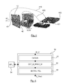
- the method (50) for predicting at least one block of pixels of a view (170) belonging to a matrix of views (17) obtained from light-field data associated with a scene, as represented on Fig. 3 is implemented by a processor and comprises, first, for at least one pixel to predict of said block of pixels, obtaining (51) at least one epipolar plane image (EPI) associated with said at least one pixel to predict by using an entity for obtaining.
- EPI epipolar plane image
- the matrix of views (17) represents a 4D light field as a collection of images of a scene (4000), where the focal points of the cameras lie in a 2D plane.
- an epipolar plane image consists in stacking all images along a line (40) of view points on top of each other, i.e. the first image (41) of the line (40) is on the top of the stack (400) as represented by the arrow (410), whereas the last image (42) of the line (40) is below the stack (400) as represented by the arrow (420). Then, a cut (401) through this stack (400) is performed along the same line (43) of each view. Such a cut is a horizontal epipolar plane image (EPI).
- EPI horizontal epipolar plane image
- the epipolar plane image is a 2D image, built by stacking one over the other, the view lines (fixed t coordinate corresponding to the view line (43)) from all views along a line of the (u,v) plane of the matrix of views (17) (fixed v coordinate corresponding to the line (40)).
- the proposed disclosure provides for at least one pixel to predict of a considered block of pixels to predict of a view of a given matrix of views at least one epipolar plane image.
- Said at least one epipolar plane image can be a horizontal epipolar plane image (EPI), a vertical epipolar plane image (EPI) or an epipolar plane image (EPI) presenting a predetermined angular orientation with respect to a horizontal or vertical epipolar plane image
- a considered pixel to predict can be associated to at least two epipolar plane images (EPI) corresponding, to a horizontal epipolar plane image (EPI) and a vertical epipolar plane image (EPI), or to a set of different angular orientations epipolar plane images (EPI).
- EPI epipolar plane images
- EPI horizontal epipolar plane image
- EPI vertical epipolar plane image
- EPI angular orientations epipolar plane images
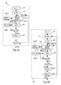
- the determining (52) of at least one optimal unidirectional prediction mode, among a set of predetermined unidirectional prediction modes and from a set of previous reconstructed pixels neighbouring said at least one pixel to predict in said at least one epipolar plane image (54) is performed using an entity for determining.
- a selection (63) of an optimal unidirectional prediction mode is performed among a set (6000) of M predetermined unidirectional prediction modes.
- such selection is performed by taking into account a set (6001) of previous reconstructed pixels neighbouring said at least one pixel to predict in the at least one epipolar plane image associated with the considered pixel to predict.
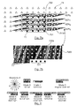
- the Fig. 7a represents the last view (42) of the lines of views (40) of the matrix of view (17) as represented in Fig. 4 .
- the block of pixels (70) is considered.
- Such a block (70) is for example surrounded by pixels (71), represented by triangles, which are previously reconstructed pixels of said view (42).
- the pixels (701) of the block of pixels (70) to predict are also surrounded by pixels (7000) in a horizontal epipolar plane image, which are also previously reconstructed pixels, represented by bold points.
- Such epipolar plane images permits to exploit the properties of the four-dimensional (4D) light field of the scene.
- the horizontal epipolar plane image hEPI 0 is associated to the pixel 702 located in the upper line of the considered block 70
- the horizontal epipolar plane image hEPI 3 is associated to the pixel 701 located in the last line of the considered block 70.
- a prediction value is extrapolated by using at least one optimal unidirectional prediction mode determined from a set of previous reconstructed pixels neighboring said pixel to predict in said at least one epipolar plane image.
- all the pixels to predict of the block of pixels (70) are predicted in the dimension corresponding to the epipolar plane images.
- a prediction value is extrapolated by using at least one optimal unidirectional prediction mode determined from a set of previous reconstructed pixels neighboring a considered pixel to predict in said at least one epipolar plane image for only a first part of the pixels belonging to said block of pixels (70).
- prediction values are obtained, using epipolar plane images, for said first part of the pixels belonging to said block of pixels (70), said prediction values are then used to predict the other part of pixels belonging to said block of pixels (70) for which no prediction value has been yet obtained.
- Said prediction of the other part of pixels belonging to said block of pixels (70) for which no prediction value has been yet obtained is performed by using classical prediction modes derived for example from the intra prediction modes of the H. 264 standard (nevertheless requiring that a side information corresponding to this intra prediction mode is transmitted to the decoder) or more simply by using a spatial interpolation (requiring less side information, since the decoder can know by default that such a spatial interpolation have to be performed once a part of the pixels to predict have been reconstructed using epipolar plane images).
- the prediction value of a pixel to predict corresponds for example to the average, or a weighting, of the values of two or more pixels neighboring it directly or not, said neighboring pixels being already reconstructed (71) or belonging to said first part and being thus already associated to a prediction value.
- the prediction value of a pixel to predict corresponds for example to the average, or a weighting, of the values of two or more pixels, already associated to a prediction value or being already reconstructed, directly neighboring it horizontally (respectively vertically).
- a prediction value can also be obtained for pixels to predict neighboring directly said block (70) of pixels (for example the pixels to predict of a line of pixels to predict located directly beneath said block (70) by using epipolar plane images so that during the following spatial interpolation a pixel to predict of said block (70) is neigbored by the number of pixels, already associated to a prediction value or being already reconstructed, required to perform the spatial interpolation.
- a part of the pixels to predict of the block of pixels (70) are first predicted in the dimension corresponding to the epipolar plane images, and, the other part of pixels is predicted using a spatial interpolation preformed within the view without using any epipolar plane images.
- a prediction value for one on two pixels is obtained by using a unidirectional prediction mode determined from epipolar plane images.
- the extrapolation of a prediction value by using epipolar plane images can be replaced by using for example a horizontal spatial interpolation performed by using the set of reconstructed pixels (71) of the considered view and the pixels of said block (70) of pixels for which a prediction value has been obtained by using epipolar plane images.
- Fig. 7b represents only the pixels 701 to predict of the last line of the considered block 70 surrounded by the previously reconstructed pixels (7000) in the horizontal epipolar plane image hEPI 3 .
- some reconstructed pixels 71 represented by triangles, belong to the same view in the same line as the pixels 701 to predict. It can be seen that the set (7000) of previous reconstructed pixels neighbouring the pixels to predict 701 corresponds to the zone to the left and top of the current pixels to predict.
- the present disclosure uses new unidirectional prediction modes exploiting the specific directional properties of epipolar plane images.
- FIG. 8 An example of a set of predetermined unidirectional prediction modes is illustrated by Fig. 8 .
- Other examples using the previously reconstructed pixels in an epipolar plane image could be easily derived.
- the prediction direction is illustrated by an arrow starting from the previously reconstructed pixels in an epipolar plane image, represented by bold points, to the pixels to predict.
- unidirectional prediction modes can be considered as being similar to the ones disclosed by the intra 4x4 prediction of the H. 264 standard, but it has to be well noticed that according to the present disclosure such modes are defined by using the previously reconstructed pixels in an epipolar plane image, which permits to exploit the properties of a the four-dimensional (4D) light field of the scene.
- the unidirectional predictions modes used according to the intra 4x4 prediction of the H.264 standard are defined by using previously reconstructed pixels in the image to encode (i.e. in a same view), which does not permit to benefit from the whole four-dimensional (4D) light field of the scene.
- the mode 8 of Fig. 8 is really different from the mode 8 of the intra 4x4 prediction of the H.264 standard since the start of the arrow is located among the previously reconstructed pixels in an epipolar plane image, represented by bold points to the pixels to predict and is "horizontal down left", whereas the arrow corresponding to the mode 8 of the intra 4x4 prediction of the H.264 standard does not start from previously reconstructed pixels in an epipolar plane image and is "horizontal up".
- the mode 2 of the intra 4x4 prediction of the H. 264 is not adapted for the prediction according to the present disclosure (i.e. no DC mode 2 is implemented according to the present disclosure), which is performed in a 4D light-field context.
- one of the predetermined unidirectional prediction modes corresponds to the unidirectional prediction mode of which the extrapolating direction is the direction from said at least one reconstructed pixel, belonging both to said at least one epipolar plane image and to said view, to said at least one pixel to predict.
- Such a mode is illustrated by the mode 1 of Fig. 8 .
- such determining (52) comprises associating a different filtering operation (F_0 j ) to each unidirectional prediction mode of said set of predetermined unidirectional prediction modes.
- Such different filtering operations are for example illustrated by Fig. 9 . More precisely, according to the example of Fig. 9 , such filtering operations are matrixes or masks, each corresponding to one unidirectional prediction modes of the set of predetermined unidirectional prediction modes of Fig. 8 .
- Other masks with a different size than a 3x3 matrix could be also used to take into account more previous reconstructed pixels neighbouring said at least one pixel to predict in said at least one epipolar plane image.
- such filtering operation is located (610) properly in the epipolar plane image so that the vertical arrow is just above the considered pixel to predict p(0,0) as represented in Fig. 10 .
- the corresponding centre positions of the convolution masks (proposed as example in Fig. 9 ) for the different directions to check in relation to the first pixel p(0,0) of the EPI line to predict are the following:
- each filtering operation i.e. mask
- each filtering operation is applied (62) to the set 7000 of the previous reconstructed pixels neighbouring said at least one pixel to predict (701) in said at least one epipolar plane image to obtain an energy level associated with each unidirectional prediction mode.
- Such energy levels correspond to spatial gradients of each direction (i.e. arrow) associated to each unidirectional prediction mode.
- the step for calculating the energy level of spatial gradients is carried out on the previous reconstructed pixels neighbouring said at least one pixel to predict (701) from the 2D masks of Fig. 9 as convolution used as window moving about in this neighbourhood.
- such application (62) of each filtering operation to said set (7000) of previous reconstructed pixels neighbouring said at least one pixel to predict p(0,0) consists in analysing the luminance signal located in the neighbouring area of the considered pixel in the epipolar plane image associated to said at least one pixel to predict.
- the calculated value of the energy level E 0 is the luminance of the pixel (0,-1) minus the luminance of the pixel (0,-3).
- E 0 Y 0 , - 1 - Y 0 , - 3 .
- Such a selection (63) consists in detecting the directions having spatial gradients with lower energy levels, such energy levels being computed in a collinear manner to the potential contours as described above.
- the optimal unidirectional prediction mode corresponds to the unidirectional prediction mode of which the energy level is the argument of the minimum of energy levels obtained for each unidirectional prediction mode such as:
- the contour neighbouring the at least one pixel to predict in the epipolar plane image is a vertical contour
- the luminance of the pixel (0,-1) and the luminance of the pixel (0,-3) will be close, leading to a very low value of energy E 0 .
- a selection (63) of an optimal unidirectional prediction mode is performed among a set (6000) of M predetermined unidirectional prediction modes.
- the method for predicting of the present disclosure further comprises providing (60) at least one group of pixels G_Pix to predict within said block of pixels B_Pix, said group of pixels G_Pix comprising at least two pixels Pg of a same line, of a same column, or of a set of at least two pixels presenting a predetermined angular orientation with respect to a line or a column of said block of pixels.
- said group of pixels G_Pix comprises G pixels.
- such a group of pixels G_Pix can correspond to the four pixels Pg 701 to predict of the same line as represented in Fig. 7b .
- the second embodiment of Fig. 6b differs from the first embodiment of Fig. 6a by the step of selecting (6300). Indeed, according to the second embodiment, a same optimal unidirectional prediction mode is selected (6300) for all pixels to predict belonging to said group of pixels, said optimal unidirectional prediction mode corresponding to the unidirectional prediction mode of which the energy level is the argument of the minimum of energy levels obtained for at least one pixel to predict of said group of pixels.
- the optimal unidirectional prediction mode is selected, for all the pixels belonging to said group of pixels G_Pix, by taking into account MxG energy levels, whereas in the first embodiment a optimal unidirectional prediction mode is selected per pixel to predict by taking into account M energy levels.
- a first variant of these two embodiments illustrated by Figs. 6a and 6b when at least two epipolar plane images (EPI) corresponding, to a horizontal epipolar plane image (EPI) and a vertical epipolar plane image (EPI), or to a set of different angular orientations epipolar plane images (EPI), are associated with one pixel to predict, determining (52) said optimal unidirectional prediction mode is performed for said horizontal epipolar plane image (EPI) and for said vertical epipolar plane image (EPI), or for a set of different angular orientations epipolar plane images (EPI), said optimal unidirectional prediction mode corresponding to the unidirectional prediction mode of which the energy level is the argument of the minimum of energy levels obtained for each epipolar plane image such as:
- the optimal unidirectional prediction mode is determined (52) for each epipolar plane image and said prediction value of said at least one pixel to predict corresponds to a mean of at least two prediction values obtained respectively by using said optimal unidirectional prediction mode determined for each epipolar plane image.
- At least one optimal unidirectional prediction mode is determined (52) according to one of the two embodiments illustrated by Figs. 6a and 6b , a prediction value of said at least one pixel to predict is extrapolated (53) by using said at least one optimal unidirectional prediction mode. Said extrapolation is performed by an entity for extrapolating.
- directions of prediction according to the present disclosure are not limited to the eight directions as represented in Fig. 8 .
- Other directions are possible with adapted masks of convolution and the associated extrapolations formulas.
- the prediction technique as previously described can be used by a matrix of view encoder.
- the present disclosure aims at providing a method for encoding (respectively decoding) an image of matrix of views and for this goal uses a new type of prediction, as disclosed above, based on the Epipolar Plane Images (EPI) representation of the matrix of views.
- EPI Epipolar Plane Images
- EPI Epipolar Plane images
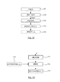
- such an encoder implements the following steps for a matrix of view obtained from light-field data associated with a scene:
- the residual error is transformed and quantized and finally entropy coded.
- the method for encoding further comprises:
- a particular signal is thus obtained comprising information representing at least one group of pixels to predict within said block of pixels.
- FIG. 12 the main steps of decoding implemented in a decoder suitable for decoding matrix of views are presented.
- the decoder receives signal representing a matrix of views encoded for example according to the encoding method described her above.
- Fig. 12 shows a decoding method in which the signal optionally (as represented in dotted lines) comprises at least one prediction residue and information representing at least one group of pixels to predict within said block of pixels.
- the method of decoding according to the invention comprises:
- the residual error is dequantized and inverse transformed reciprocally to the process performed during the encoding.
- the modules are functional units, which may or not be in relation with distinguishable physical units. For example, these modules or some of them may be brought together in a unique component or circuit, or contribute to functionalities of a software. A contrario, some modules may potentially be composed of separate physical entities.
- the apparatus which are compatible with the disclosure are implemented using either pure hardware, for example using dedicated hardware such ASIC or FPGA or VLSI, respectively « Application Specific Integrated Circuit » « Field-Programmable Gate Array » « Very Large Scale Integration » or from several integrated electronic components embedded in a device or from a blend of hardware and software components.
- Fig. 13 represents an exemplary architecture of a device 1300 which may be configured to implement a predicting method described in relation with Fig. 1-10 , an encoding method in relation with Fig. 11 , or a decoding method in relation with Fig. 12 .
- Device 1300 comprises following elements that are linked together by a data and address bus 1301:
- the battery 1306 is external to the device.
- the word « register » used in the specification can correspond to area of small capacity (some bits) or to very large area (e.g. a whole program or large amount of received or decoded data).
- ROM 1302 comprises at least a program and parameters. Algorithm of the methods according to the disclosure is stored in the ROM 1302. When switched on, the CPU 1303 uploads the program in the RAM and executes the corresponding instructions.
- RAM 1304 comprises, in a register, the program executed by the CPU 1303 and uploaded after switch on of the device 1300, input data in a register, intermediate data in different states of the method in a register, and other variables used for the execution of the method in a register.
- the implementations described herein may be implemented in, for example, a method or a process, an apparatus, a software program, a data stream, or a signal. Even if only discussed in the context of a single form of implementation (for example, discussed only as a method or a device), the implementation of features discussed may also be implemented in other forms (for example a program).
- An apparatus may be implemented in, for example, appropriate hardware, software, and firmware.
- the methods may be implemented in, for example, an apparatus such as, for example, a processor, which refers to processing devices in general, including, for example, a computer, a microprocessor, an integrated circuit, or a programmable logic device. Processors also include communication devices, such as, for example, computers, cell phones, portable/personal digital assistants ("PDAs”), and other devices that facilitate communication of information between end-users.
- PDAs portable/personal digital assistants
- said matrix of views is obtained from a source.
- the source belongs to a set comprising:
- the decoded matrix of views is sent to a destination; specifically, the destination belongs to a set comprising:
- a bitstream delivered by said encoder is sent to a destination.
- said bitstream is stored in a local or remote memory, e.g. a video memory (1304) or a RAM (1304), a hard disk (1302).
- said bitstreams is sent to a storage interface, e.g. an interface with a mass storage, a flash memory, ROM, an optical disc or a magnetic support and/or transmitted over a communication interface (1305), e.g. an interface to a point to point link, a communication bus, a point to multipoint link or a broadcast network.
- a bitstream is obtained from a source.
- the bitstream is read from a local memory, e.g. a video memory (1304), a RAM (1304), a ROM (1302), a flash memory (1302) or a hard disk (1302).
- the bitstream is received from a storage interface, e.g. an interface with a mass storage, a RAM, a ROM, a flash memory, an optical disc or a magnetic support and/or received from a communication interface (1305), e.g. an interface to a point to point link, a bus, a point to multipoint link or a broadcast network.
- Implementations of the various processes and features described herein may be embodied in a variety of different equipment or applications.
- Examples of such equipment include an encoder, a decoder, a post-processor processing output from a decoder, a preprocessor providing input to an encoder, a video coder, a video decoder, a video codec, a web server, a set-top box, a laptop, a personal computer, a cell phone, a PDA, and any other device for processing a picture or a video or other communication devices.
- the equipment may be mobile and even installed in a mobile vehicle.
- a computer readable storage medium can take the form of a computer readable program product embodied in one or more computer readable medium(s) and having computer readable program code embodied thereon that is executable by a computer.
- a computer readable storage medium as used herein is considered a non-transitory storage medium given the inherent capability to store the information therein as well as the inherent capability to provide retrieval of the information therefrom.
- a computer readable storage medium can be, for example, but is not limited to, an electronic, magnetic, optical, electromagnetic, infrared, or semiconductor system, apparatus, or device, or any suitable combination of the foregoing. It is to be appreciated that the following, while providing more specific examples of computer readable storage mediums to which the present principles can be applied, is merely an illustrative and not exhaustive listing as is readily appreciated by one of ordinary skill in the art: a portable computer diskette; a hard disk; a read-only memory (ROM); an erasable programmable read-only memory (EPROM or Flash memory); a portable compact disc read-only memory (CD-ROM); an optical storage device; a magnetic storage device; or any suitable combination of the foregoing.
- the instructions may form an application program tangibly embodied on a processor-readable medium.
- Instructions may be, for example, in hardware, firmware, software, or a combination. Instructions may be found in, for example, an operating system, a separate application, or a combination of the two.
- a processor may be characterized, therefore, as, for example, both a device configured to carry out a process and a device that includes a processor-readable medium (such as a storage device) having instructions for carrying out a process. Further, a processor-readable medium may store, in addition to or in lieu of instructions, data values produced by an implementation.
- implementations may produce a variety of signals formatted to carry information that may be, for example, stored or transmitted.
- the information may include, for example, instructions for performing a method, or data produced by one of the described implementations.
- a signal may be formatted to carry as data the rules for writing or reading the syntax of a described embodiment, or to carry as data the actual syntax-values written by a described embodiment.
- Such a signal may be formatted, for example, as an electromagnetic wave (for example, using a radio frequency portion of spectrum) or as a baseband signal.
- the formatting may include, for example, encoding a data stream and modulating a carrier with the encoded data stream.
- the information that the signal carries may be, for example, analog or digital information.
- the signal may be transmitted over a variety of different wired or wireless links, as is known.
- the signal may be stored on a processor-readable medium.
Landscapes
- Engineering & Computer Science (AREA)
- Multimedia (AREA)
- Signal Processing (AREA)
- Compression Or Coding Systems Of Tv Signals (AREA)
Priority Applications (7)
| Application Number | Priority Date | Filing Date | Title |
|---|---|---|---|
| EP15306409.2A EP3142366A1 (fr) | 2015-09-14 | 2015-09-14 | Procédé et appareil de codage et de décodage d'une image basée sur un champ de lumière et produit programme d'ordinateur correspondant |
| EP16769921.4A EP3351000A1 (fr) | 2015-09-14 | 2016-09-14 | Procédé et appareil d'encodage et décodage d'une image basée sur un champ de lumière, et produit programme d'ordinateur correspondant |
| US15/759,564 US10785502B2 (en) | 2015-09-14 | 2016-09-14 | Method and apparatus for encoding and decoding a light field based image, and corresponding computer program product |
| CN201680065314.7A CN108293133A (zh) | 2015-09-14 | 2016-09-14 | 用于编码和解码基于光场的图像的方法和装置及对应计算机程序产品 |
| PCT/EP2016/071717 WO2017046176A1 (fr) | 2015-09-14 | 2016-09-14 | Procédé et appareil d'encodage et décodage d'une image basée sur un champ de lumière, et produit programme d'ordinateur correspondant |
| JP2018513479A JP6872533B2 (ja) | 2015-09-14 | 2016-09-14 | ライトフィールドベース画像を符号化および復号する方法および装置、および対応するコンピュータプログラム製品 |
| KR1020187007404A KR20180053665A (ko) | 2015-09-14 | 2016-09-14 | 광 필드 기반 이미지를 인코딩 및 디코딩하는 방법 및 장치 그리고 대응하는 컴퓨터 프로그램 제품 |
Applications Claiming Priority (1)
| Application Number | Priority Date | Filing Date | Title |
|---|---|---|---|
| EP15306409.2A EP3142366A1 (fr) | 2015-09-14 | 2015-09-14 | Procédé et appareil de codage et de décodage d'une image basée sur un champ de lumière et produit programme d'ordinateur correspondant |
Publications (1)
| Publication Number | Publication Date |
|---|---|
| EP3142366A1 true EP3142366A1 (fr) | 2017-03-15 |
Family
ID=54249415
Family Applications (2)
| Application Number | Title | Priority Date | Filing Date |
|---|---|---|---|
| EP15306409.2A Withdrawn EP3142366A1 (fr) | 2015-09-14 | 2015-09-14 | Procédé et appareil de codage et de décodage d'une image basée sur un champ de lumière et produit programme d'ordinateur correspondant |
| EP16769921.4A Ceased EP3351000A1 (fr) | 2015-09-14 | 2016-09-14 | Procédé et appareil d'encodage et décodage d'une image basée sur un champ de lumière, et produit programme d'ordinateur correspondant |
Family Applications After (1)
| Application Number | Title | Priority Date | Filing Date |
|---|---|---|---|
| EP16769921.4A Ceased EP3351000A1 (fr) | 2015-09-14 | 2016-09-14 | Procédé et appareil d'encodage et décodage d'une image basée sur un champ de lumière, et produit programme d'ordinateur correspondant |
Country Status (6)
| Country | Link |
|---|---|
| US (1) | US10785502B2 (fr) |
| EP (2) | EP3142366A1 (fr) |
| JP (1) | JP6872533B2 (fr) |
| KR (1) | KR20180053665A (fr) |
| CN (1) | CN108293133A (fr) |
| WO (1) | WO2017046176A1 (fr) |
Families Citing this family (7)
| Publication number | Priority date | Publication date | Assignee | Title |
|---|---|---|---|---|
| US11051039B2 (en) | 2017-06-02 | 2021-06-29 | Ostendo Technologies, Inc. | Methods for full parallax light field compression |
| EP3422722A1 (fr) * | 2017-06-30 | 2019-01-02 | Thomson Licensing | Procédé de codage dune matrice de vues d'images obtenues à partir de données acquises par une caméra à fonction plénoptique |
| US10931956B2 (en) | 2018-04-12 | 2021-02-23 | Ostendo Technologies, Inc. | Methods for MR-DIBR disparity map merging and disparity threshold determination |
| EP3579561A1 (fr) * | 2018-06-05 | 2019-12-11 | InterDigital VC Holdings, Inc. | Prédiction pour le codage et le décodage de champ de lumière |
| US11172222B2 (en) * | 2018-06-26 | 2021-11-09 | Ostendo Technologies, Inc. | Random access in encoded full parallax light field images |
| US11457197B2 (en) * | 2019-02-22 | 2022-09-27 | Avalon Holographics Inc. | Layered scene decomposition CODEC with view independent rasterization |
| BR102021009291A2 (pt) * | 2021-05-13 | 2022-11-22 | Samsung Eletrônica da Amazônia Ltda. | Método de intrapredição quadridimensional para codificação e decodificação de dados de light field |
Citations (1)
| Publication number | Priority date | Publication date | Assignee | Title |
|---|---|---|---|---|
| US20130222633A1 (en) | 2012-02-28 | 2013-08-29 | Lytro, Inc. | Light-field processing and analysis, camera control, and user interfaces and interaction on light-field capture devices |
Family Cites Families (10)
| Publication number | Priority date | Publication date | Assignee | Title |
|---|---|---|---|---|
| US5703961A (en) * | 1994-12-29 | 1997-12-30 | Worldscape L.L.C. | Image transformation and synthesis methods |
| US6097394A (en) | 1997-04-28 | 2000-08-01 | Board Of Trustees, Leland Stanford, Jr. University | Method and system for light field rendering |
| JP4825984B2 (ja) * | 2005-08-29 | 2011-11-30 | 国立大学法人名古屋大学 | 画像情報圧縮方法、画像情報圧縮装置、及び自由視点テレビシステム |
| US8290289B2 (en) | 2006-09-20 | 2012-10-16 | Nippon Telegraph And Telephone Corporation | Image encoding and decoding for multi-viewpoint images |
| CA2663084C (fr) | 2006-09-20 | 2014-08-12 | Nippon Telegraph And Telephone Corporation | Procedes et dispositifs de codage et de decodage d'image, dispositif et programmes de decodage d'image, et support de stockage desdits programmes |
| US7822280B2 (en) | 2007-01-16 | 2010-10-26 | Microsoft Corporation | Epipolar geometry-based motion estimation for multi-view image and video coding |
| WO2010086544A1 (fr) * | 2009-01-28 | 2010-08-05 | France Telecom | Procede et dispositif de codage d'une image utilisant un masque de prediction, procede et dispositif de decodage, signal et programmes d'ordinateur correspondants |
| WO2010102935A1 (fr) | 2009-03-09 | 2010-09-16 | Thomson Licensing | Estimation du mode de prédiction pour le mode de codage intra |
| US9462164B2 (en) | 2013-02-21 | 2016-10-04 | Pelican Imaging Corporation | Systems and methods for generating compressed light field representation data using captured light fields, array geometry, and parallax information |
| US9712820B2 (en) * | 2014-04-24 | 2017-07-18 | Lytro, Inc. | Predictive light field compression |
-
2015
- 2015-09-14 EP EP15306409.2A patent/EP3142366A1/fr not_active Withdrawn
-
2016
- 2016-09-14 WO PCT/EP2016/071717 patent/WO2017046176A1/fr active Application Filing
- 2016-09-14 EP EP16769921.4A patent/EP3351000A1/fr not_active Ceased
- 2016-09-14 KR KR1020187007404A patent/KR20180053665A/ko not_active Application Discontinuation
- 2016-09-14 US US15/759,564 patent/US10785502B2/en active Active
- 2016-09-14 JP JP2018513479A patent/JP6872533B2/ja active Active
- 2016-09-14 CN CN201680065314.7A patent/CN108293133A/zh active Pending
Patent Citations (1)
| Publication number | Priority date | Publication date | Assignee | Title |
|---|---|---|---|---|
| US20130222633A1 (en) | 2012-02-28 | 2013-08-29 | Lytro, Inc. | Light-field processing and analysis, camera control, and user interfaces and interaction on light-field capture devices |
Non-Patent Citations (9)
| Title |
|---|
| B. GOLDLUECKE ET AL.: "The Variational Structure of Disparity and Regularization of 4D Light Fields''", IEEE CONFERENCE ON COMPUTER VISION AND PATTERN RECOGNITION, 2013, pages 1003 - 1010 |
| B. GOLDLUECKE ET AL.: "The Variational Structure of Disparity and Regularization of 4D Light Fields", IEEE CONFERENCE ON COMPUTER VISION AND PATTERN RECOGNITION, 2013, pages 1003 - 1010 |
| BOLLES R C ET AL: "EPIPOLAR-PLANE IMAGE ANALYSIS: AN APPROACH TO DETERMINING STRUCTUREFROM MOTION", INTERNATIONAL JOURNAL OF COMPUTER VISION, DORDRECHT, NL, 1 January 1987 (1987-01-01), pages 7 - 55, XP000572465, DOI: 10.1007/BF00128525 * |
| GUOLEI YANG ET AL: "Fast intra mode selection for stereo video coding using epipolar constraint", VISUAL COMMUNICATIONS AND IMAGE PROCESSING (VCIP), 2011 IEEE, IEEE, 6 November 2011 (2011-11-06), pages 1 - 4, XP032081407, ISBN: 978-1-4577-1321-7, DOI: 10.1109/VCIP.2011.6116013 * |
| HEUNG-YEUNG SHUM ET AL: "Survey of image-based representations and compression techniques", IEEE TRANSACTIONS ON CIRCUITS AND SYSTEMS FOR VIDEO TECHNOLOGY, IEEE SERVICE CENTER, PISCATAWAY, NJ, US, vol. 13, no. 11, 1 November 2003 (2003-11-01), pages 1020 - 1037, XP011102938, ISSN: 1051-8215, DOI: 10.1109/TCSVT.2003.817360 * |
| N. SABATER ET AL.: "Light field demultiplexing and disparity estimation", INTERNATIONAL CONFERENCE ON COMPLEMENTARY PROBLEMS ICCP, 2014 |
| R. NG ET AL.: "Light field photography with a hand-held plenoptic camera", STANDFORD UNIVERSITY COMPUTER SCIENCE TECHNICAL REPORT CSTR 2005-02, April 2005 (2005-04-01) |
| T. WIEGAND ET AL.: "Lagrange Multiplier Selection in Hybrid Video Coder Control", IEEE INTERNATIONAL CONFERENCE ON IMAGE PROCESSING, vol. 3, 2001, pages 542 - 545 |
| ZHONG XUE ET AL: "An Automatic Mode Decision Method for Intra Frame Coding and Decoding", 58. MPEG MEETING; 03-12-2001 - 07-12-2001; PATTAYA; (MOTION PICTUREEXPERT GROUP OR ISO/IEC JTC1/SC29/WG11),, no. M7719, 26 November 2001 (2001-11-26), XP030036810, ISSN: 0000-0279 * |
Also Published As
| Publication number | Publication date |
|---|---|
| JP2018533273A (ja) | 2018-11-08 |
| JP6872533B2 (ja) | 2021-05-19 |
| CN108293133A (zh) | 2018-07-17 |
| US10785502B2 (en) | 2020-09-22 |
| US20190158877A1 (en) | 2019-05-23 |
| WO2017046176A1 (fr) | 2017-03-23 |
| EP3351000A1 (fr) | 2018-07-25 |
| KR20180053665A (ko) | 2018-05-23 |
Similar Documents
| Publication | Publication Date | Title |
|---|---|---|
| US10652577B2 (en) | Method and apparatus for encoding and decoding light field based image, and corresponding computer program product | |
| US10785502B2 (en) | Method and apparatus for encoding and decoding a light field based image, and corresponding computer program product | |
| EP3348060B1 (fr) | Procédé et appareil de codage d'une image basé sur un champ de lumière et produit programme d'ordinateur correspondant | |
| Li et al. | Scalable coding of plenoptic images by using a sparse set and disparities | |
| GB2535475A (en) | Optimized plenoptic image encoding | |
| US20180278955A1 (en) | Method and apparatus for reducing the coding artefact of a light field based image, and corresponding computer program product | |
| CN111416983B (zh) | 基于成像相关的多焦距光场视频帧内预测方法和装置 | |
| US20170150152A1 (en) | Methods and devices for encoding and decoding a matrix of views obtained from light-field data, corresponding computer program and non-transitory program storage device | |
| Perra et al. | An analysis of HEVC compression for light field image refocusing applications | |
| US10580210B2 (en) | Method and device for refocusing at least one plenoptic video | |
| EP3203742A1 (fr) | Système et procédé pour coder et décoder des informations représentatives d'une distance de focalisation associées à une image appartenant à une pile focale représentative d'un contenu de champ lumineux | |
| EP3185560A1 (fr) | Système et procédé de codage et de décodage d'informations représentatives d'un modèle bokeh devant être appliquées à un contenu de champ lumineux totalement mise au point | |
| EP3200151A1 (fr) | Procédé et dispositif permettant d'obtenir une carte de profondeur | |
| GB2539417A (en) | Optimized multi-view image encoding | |
| Phi | Perceptually Optimized Plenoptic Data Representation and Coding |
Legal Events
| Date | Code | Title | Description |
|---|---|---|---|
| PUAI | Public reference made under article 153(3) epc to a published international application that has entered the european phase |
Free format text: ORIGINAL CODE: 0009012 |
|
| AK | Designated contracting states |
Kind code of ref document: A1 Designated state(s): AL AT BE BG CH CY CZ DE DK EE ES FI FR GB GR HR HU IE IS IT LI LT LU LV MC MK MT NL NO PL PT RO RS SE SI SK SM TR |
|
| AX | Request for extension of the european patent |
Extension state: BA ME |
|
| STAA | Information on the status of an ep patent application or granted ep patent |
Free format text: STATUS: THE APPLICATION IS DEEMED TO BE WITHDRAWN |
|
| 18D | Application deemed to be withdrawn |
Effective date: 20170916 |