EP3142278B1 - Modulation processing method and apparatus for high-order coding, base station, and terminal - Google Patents
Modulation processing method and apparatus for high-order coding, base station, and terminal Download PDFInfo
- Publication number
- EP3142278B1 EP3142278B1 EP14891460.9A EP14891460A EP3142278B1 EP 3142278 B1 EP3142278 B1 EP 3142278B1 EP 14891460 A EP14891460 A EP 14891460A EP 3142278 B1 EP3142278 B1 EP 3142278B1
- Authority
- EP
- European Patent Office
- Prior art keywords
- base station
- supporting
- uplink
- order modulation
- downlink control
- Prior art date
- Legal status (The legal status is an assumption and is not a legal conclusion. Google has not performed a legal analysis and makes no representation as to the accuracy of the status listed.)
- Active
Links
Images

Classifications
-
- H—ELECTRICITY
- H04—ELECTRIC COMMUNICATION TECHNIQUE
- H04L—TRANSMISSION OF DIGITAL INFORMATION, e.g. TELEGRAPHIC COMMUNICATION
- H04L27/00—Modulated-carrier systems
- H04L27/32—Carrier systems characterised by combinations of two or more of the types covered by groups H04L27/02, H04L27/10, H04L27/18 or H04L27/26
- H04L27/34—Amplitude- and phase-modulated carrier systems, e.g. quadrature-amplitude modulated carrier systems
- H04L27/36—Modulator circuits; Transmitter circuits
-
- H—ELECTRICITY
- H04—ELECTRIC COMMUNICATION TECHNIQUE
- H04L—TRANSMISSION OF DIGITAL INFORMATION, e.g. TELEGRAPHIC COMMUNICATION
- H04L1/00—Arrangements for detecting or preventing errors in the information received
- H04L1/0001—Systems modifying transmission characteristics according to link quality, e.g. power backoff
- H04L1/0023—Systems modifying transmission characteristics according to link quality, e.g. power backoff characterised by the signalling
- H04L1/0027—Scheduling of signalling, e.g. occurrence thereof
-
- H—ELECTRICITY
- H04—ELECTRIC COMMUNICATION TECHNIQUE
- H04L—TRANSMISSION OF DIGITAL INFORMATION, e.g. TELEGRAPHIC COMMUNICATION
- H04L1/00—Arrangements for detecting or preventing errors in the information received
- H04L1/0001—Systems modifying transmission characteristics according to link quality, e.g. power backoff
-
- H—ELECTRICITY
- H03—ELECTRONIC CIRCUITRY
- H03C—MODULATION
- H03C7/00—Modulating electromagnetic waves
- H03C7/02—Modulating electromagnetic waves in transmission lines, waveguides, cavity resonators or radiation fields of antennas
-
- H—ELECTRICITY
- H04—ELECTRIC COMMUNICATION TECHNIQUE
- H04L—TRANSMISSION OF DIGITAL INFORMATION, e.g. TELEGRAPHIC COMMUNICATION
- H04L1/00—Arrangements for detecting or preventing errors in the information received
-
- H—ELECTRICITY
- H04—ELECTRIC COMMUNICATION TECHNIQUE
- H04L—TRANSMISSION OF DIGITAL INFORMATION, e.g. TELEGRAPHIC COMMUNICATION
- H04L1/00—Arrangements for detecting or preventing errors in the information received
- H04L1/0001—Systems modifying transmission characteristics according to link quality, e.g. power backoff
- H04L1/0002—Systems modifying transmission characteristics according to link quality, e.g. power backoff by adapting the transmission rate
- H04L1/0003—Systems modifying transmission characteristics according to link quality, e.g. power backoff by adapting the transmission rate by switching between different modulation schemes
-
- H—ELECTRICITY
- H04—ELECTRIC COMMUNICATION TECHNIQUE
- H04L—TRANSMISSION OF DIGITAL INFORMATION, e.g. TELEGRAPHIC COMMUNICATION
- H04L1/00—Arrangements for detecting or preventing errors in the information received
- H04L1/0001—Systems modifying transmission characteristics according to link quality, e.g. power backoff
- H04L1/0009—Systems modifying transmission characteristics according to link quality, e.g. power backoff by adapting the channel coding
-
- H—ELECTRICITY
- H04—ELECTRIC COMMUNICATION TECHNIQUE
- H04L—TRANSMISSION OF DIGITAL INFORMATION, e.g. TELEGRAPHIC COMMUNICATION
- H04L1/00—Arrangements for detecting or preventing errors in the information received
- H04L1/0001—Systems modifying transmission characteristics according to link quality, e.g. power backoff
- H04L1/0023—Systems modifying transmission characteristics according to link quality, e.g. power backoff characterised by the signalling
- H04L1/0026—Transmission of channel quality indication
-
- H—ELECTRICITY
- H04—ELECTRIC COMMUNICATION TECHNIQUE
- H04L—TRANSMISSION OF DIGITAL INFORMATION, e.g. TELEGRAPHIC COMMUNICATION
- H04L1/00—Arrangements for detecting or preventing errors in the information received
- H04L1/0001—Systems modifying transmission characteristics according to link quality, e.g. power backoff
- H04L1/0023—Systems modifying transmission characteristics according to link quality, e.g. power backoff characterised by the signalling
- H04L1/0028—Formatting
- H04L1/003—Adaptive formatting arrangements particular to signalling, e.g. variable amount of bits
-
- H—ELECTRICITY
- H04—ELECTRIC COMMUNICATION TECHNIQUE
- H04L—TRANSMISSION OF DIGITAL INFORMATION, e.g. TELEGRAPHIC COMMUNICATION
- H04L1/00—Arrangements for detecting or preventing errors in the information received
- H04L1/004—Arrangements for detecting or preventing errors in the information received by using forward error control
-
- H—ELECTRICITY
- H04—ELECTRIC COMMUNICATION TECHNIQUE
- H04L—TRANSMISSION OF DIGITAL INFORMATION, e.g. TELEGRAPHIC COMMUNICATION
- H04L25/00—Baseband systems
- H04L25/02—Details ; arrangements for supplying electrical power along data transmission lines
- H04L25/03—Shaping networks in transmitter or receiver, e.g. adaptive shaping networks
- H04L25/03828—Arrangements for spectral shaping; Arrangements for providing signals with specified spectral properties
- H04L25/03866—Arrangements for spectral shaping; Arrangements for providing signals with specified spectral properties using scrambling
-
- H—ELECTRICITY
- H04—ELECTRIC COMMUNICATION TECHNIQUE
- H04L—TRANSMISSION OF DIGITAL INFORMATION, e.g. TELEGRAPHIC COMMUNICATION
- H04L65/00—Network arrangements, protocols or services for supporting real-time applications in data packet communication
- H04L65/60—Network streaming of media packets
- H04L65/70—Media network packetisation
-
- H—ELECTRICITY
- H04—ELECTRIC COMMUNICATION TECHNIQUE
- H04L—TRANSMISSION OF DIGITAL INFORMATION, e.g. TELEGRAPHIC COMMUNICATION
- H04L67/00—Network arrangements or protocols for supporting network services or applications
- H04L67/01—Protocols
- H04L67/04—Protocols specially adapted for terminals or networks with limited capabilities; specially adapted for terminal portability
-
- H—ELECTRICITY
- H04—ELECTRIC COMMUNICATION TECHNIQUE
- H04W—WIRELESS COMMUNICATION NETWORKS
- H04W72/00—Local resource management
- H04W72/20—Control channels or signalling for resource management
- H04W72/21—Control channels or signalling for resource management in the uplink direction of a wireless link, i.e. towards the network
-
- H—ELECTRICITY
- H04—ELECTRIC COMMUNICATION TECHNIQUE
- H04L—TRANSMISSION OF DIGITAL INFORMATION, e.g. TELEGRAPHIC COMMUNICATION
- H04L1/00—Arrangements for detecting or preventing errors in the information received
- H04L2001/0092—Error control systems characterised by the topology of the transmission link
-
- H—ELECTRICITY
- H04—ELECTRIC COMMUNICATION TECHNIQUE
- H04L—TRANSMISSION OF DIGITAL INFORMATION, e.g. TELEGRAPHIC COMMUNICATION
- H04L27/00—Modulated-carrier systems
- H04L27/0014—Carrier regulation
- H04L2027/0083—Signalling arrangements
- H04L2027/0097—Adaptive synchronisation signals
-
- H—ELECTRICITY
- H04—ELECTRIC COMMUNICATION TECHNIQUE
- H04W—WIRELESS COMMUNICATION NETWORKS
- H04W72/00—Local resource management
- H04W72/20—Control channels or signalling for resource management
- H04W72/23—Control channels or signalling for resource management in the downlink direction of a wireless link, i.e. towards a terminal
Definitions
- the present invention relates to the field of communications, and in particular, to a modulation processing method and apparatus for high-order coding, a base station and a terminal.
- a communication process has a lot of uncertainty.
- high-order modulation with a high transmission rate and less redundant error correction codes are used for communication.
- the throughput of the system is indeed improved greatly when a signal-to-noise ratio of the wireless fading channel is ideal.
- low-order modulation with a low transmission rate and large redundant error correction codes are used for communication. That is, when the channel is in deep fading, it can be guaranteed that the communication is reliable and stable.
- an adaptive modulation and coding technology which belongs to the most typical link adaptation technology.
- the CSI includes a Channel Quality Indication (CQI), a Pre-coding Matrix Indicator (PMI), and a Rank Indicator (RI).
- CQI Channel Quality Indication
- PMI Pre-coding Matrix Indicator
- RI Rank Indicator
- the CSI reflects the state of the downlink physical channel.
- the base station performs downlink scheduling as well as modulation and coding of data using the CSI.
- the base station performs scheduling using the CSI reported by the terminal and determines a downlink Modulation and Coding Scheme (MCS) index and resource allocation information.
- MCS Modulation and Coding Scheme
- the Rel-8 LTE protocol defines a modulation and Transport Block Size (TBS) index table for a Physical Downlink Shared Channel (PDSCH), which may be referred to as a downlink MCS table hereinafter.
- TBS modulation and Transport Block Size
- PDSCH Physical Downlink Shared Channel
- PDSCH Physical Downlink Shared Channel
- PDSCH Physical Downlink Shared Channel
- the table has a total of 32 levels. Each level basically corresponds to a MCS index, and each MCS index essentially corresponds to a MCS.
- the resource allocation information gives a Number Physical Resource Block (NPRB) which need to be occupied by the downlink transmission.
- NPRB Number Physical Resource Block
- the LTE standard also provides a TBS table. After the MCS index and the NPRB are given, the TBS can be
- the terminal After the terminal receives the data of the downlink transmission, it needs to obtain the MCS index and the resource allocation information of the downlink transmission for data processing. Further, the base station transmits the MCS index and the resource allocation information through Downlink Control Information (DCI).
- DCI Downlink Control Information
- the base station scrambles Cyclic Redundancy Check (CRC) bits corresponding to the downlink control information using a specific Radio Network Temporary Identity (RNTI), and transmits the downlink control information in a specific DCI format through a Physical Downlink Control Channel (PDCCH).
- the terminal carries out blind detection in a Common Search Space (CSS) and a User Equipment (UE) specific Search Space (USS) to acquire the downlink control information.
- CCS Common Search Space
- UE User Equipment
- USS User Equipment
- DCI formats related to the PDSCH include DCI format 1, DCI format 1A, DCI format 1B, DCI format 1C, DCI format ID, DCI format 2, DCI format 2A, DCI format 2B, DCI format 2C, DCI format 2D etc.
- the base station can acquire uplink channel parameters from a Sounding Reference Signal (SRS) transmitted by the UE and determine the MCS index and the resource allocation information for the uplink transmission of the UE based on the acquired channel parameters.
- SRS Sounding Reference Signal
- the Rel-8 LTE protocol defines a Modulation and TBS index table for a Physical Uplink Shared Channel (PUSCH), which may also be referred to as an uplink MCS table hereinafter.
- the base station transmits the MCS index and the resource allocation information through the downlink control information.
- the terminal can carry out the modulation and coding of the uplink data using the information and transmit the uplink data on a corresponding PUSCH resource.
- the DCI format associated with PUSCH includes DCI format 0, DCI format 3, DCI format 3A, and DCI format 4. It should be illustrated that the downlink MCS table and the uplink MCS table can be collectively referred to as a MCS table.
- the uplink and the downlink support a modulation and coding scheme of at most 64 Quadrature Amplitude Modulation (QAM).
- QAM Quadrature Amplitude Modulation
- a conventional table of the existing LTE standard i.e., the CQI table/MCS table/TBS table supports a modulation and coding scheme of at most 64 QAM and a spectral efficiency of about 5.5547 bit/s/Hz.
- the conventional table i.e., the existing CQI table, MCS table and TBS table
- the conventional table cannot support a higher-order modulation.
- enhanced tables new CQI, MCS and TBS tables supporting the high-order modulation should be designed.
- the conventional table of the communication system can neither support the higher-order modulation, nor can solve the problem of the specific configuration and usage of the enhanced table for the high-order modulation and the conventional table. Therefore, the communication system currently cannot support the higher-order modulation. In scenarios where the channel conditions are good and higher-order modulations may be applied, for example, in small cell scenarios, the improvement of the peak data transmission rate and the spectral efficiency of the system is limited.
- the present invention provides a modulation processing method and apparatus for high-order coding, a base station and a terminal.
- a modulation processing method for high-order coding including: a base station selecting a Modulation and Coding Scheme (MCS) table according to a transmission type and predefined information, herein the MCS table includes a MCS table supporting a M-order modulation and a MCS table not supporting a M-order modulation, herein M>64; and the base station transmitting the downlink control signaling to a terminal, the downlink control signaling including a modulation and coding scheme field I MCS , herein the I MCS is based on the MCS table supporting or not supporting a M-order modulation selected by the base station.
- MCS Modulation and Coding Scheme
- a base station selecting a MCS table according to a transmission type and predefined information includes: when the transmission type is downlink transmission, the base station selecting a downlink MCS table according to the predefined information, herein the predefined information includes: a table type configured for a sub frame set, herein the table type is a Channel Quality Indication (CQI) table supporting a M-order modulation or a CQI table not supporting a M-order modulation.
- CQI Channel Quality Indication
- the subframe set includes: subframe set 0 and/or subframe set 1 configured by the base station.
- the DCI format includes at least one of DCI format 0 and DCI format 4.
- the method when the base station selects an uplink MCS table according to the table type configured during downlink transmission, the method further includes at least one of: when the CQI table supporting a M-order modulation and/or the MCS table supporting a M-order modulation is configured for the downlink transmission, configuring an uplink MCS table supporting a M-order modulation for uplink transmission in a specific scenario; when the CQI table supporting a M-order modulation and/or the MCS table supporting a M-order modulation is configured for the downlink transmission and Channel State Information (CSI) is transmitted on a Physical Uplink Shared Channel (PUSCH) for uplink transmission in a specific scenario, configuring an uplink MCS table not supporting a M-order modulation for the uplink transmission; and selecting an uplink MCS table supporting or not supporting a M-order modulation for the uplink transmission through configuration signaling sent by the base station.
- CSI Channel State Information
- the specific scenario includes Time Division Duplex (TDD) transmission.
- TDD Time Division Duplex
- the method further includes at least one of: when the base station configures uplink transmission mode 1 for the terminal or the DCI format is only configured as DCI format 0, if the search space corresponding to the downlink control signaling is a common search space, the base station selecting an uplink MCS table not supporting a M-order modulation, and if the search space corresponding to the downlink control signaling is a UE-specific search space, the base station selecting an uplink MCS table supporting a M-order modulation; when the base station configures the uplink transmission mode 1 for the terminal or the DCI format is only configured as the DCI format 0, if the CRC scrambling mode corresponding to the downlink control signaling is SPS C-RNTI scrambling, the base station selecting an uplink MCS
- the method further includes at least one of: the base station respectively configuring an uplink MCS table supporting or not supporting a M-order modulation for a subframe set 2 and a subframe set 3, the subframe set 2 and the subframe set 3 being uplink subframe sets configured by the base station or predefined subframe sets; the base station only configuring an uplink MCS table supporting or not supporting a M-order modulation for the subframe set 2, and using an uplink MCS table not supporting a M-order modulation for the subframe set 3, and the base station only configuring an uplink MCS table supporting or not supporting a M-order modulation for the subframe set 3, and using an uplink MCS table not supporting a M-order modulation for the subframe set 2.
- the base station transmits the downlink control signaling to the terminal, the downlink control signaling including: a Transmission Power Control (TPC) command field, herein the TPC command field includes at least one of the following characteristics: when the downlink control signaling is transmitted through DCI format 3A, the TPC command field is represented by N1 bits, herein N1 is a positive integer not less than 1, and the value of TPC command corresponding to the TPC command field includes an integer other than -1 and 1; and when the downlink control signaling is transmitted through a DCI format other than the DCI format 3A, the TPC command field is represented by N2 bits, herein N2 is a positive integer equal to or greater than 2, and the value of TPC command corresponding to the TPC command field includes an integer other than -1, 0, 1 and 3.
- TPC Transmission Power Control
- a modulation processing method for high-order coding including: a terminal receiving downlink control signaling transmitted by a base station, the downlink control signaling including a modulation and coding scheme field I MCS , herein the I MCS is based on a Modulation and Coding Scheme (MCS) table selected by the base station according to a transmission type and predefined information, herein the MCS table includes a MCS table supporting a M-order modulation and a MCS table not supporting a M-order modulation, herein M>64; and the terminal implementing modulation and coding on uplink data or implementing demodulation and decoding on downlink data according to I MCS .
- MCS Modulation and Coding Scheme
- the base station selecting a downlink MCS table according to the predefined information includes: a table type configured for a sub frame set, herein the table type is a Channel Quality Indication (CQI) table supporting a M-order modulation or a CQI table not supporting a M-order modulation.
- CQI Channel Quality Indication
- the subframe set includes: subframe set 0 and/or subframe set 1 configured by the base station.
- the base station selecting an uplink MCS table according to the predefined information
- the predefined information includes at least one of: a table type configured during downlink transmission, the table type including at least one of a CQI table supporting a M-order modulation and a MCS table supporting a M-order modulation, a DCI format, herein the DCI carries the modulation and coding scheme field I MCS ; a search space corresponding to downlink control signaling, the search space including at least one of: a common search space and a UE-specific search space, herein the downlink control signaling carries the modulation and coding scheme field I MCS ; a Cyclic Redundancy Check (CRC) scrambling mode corresponding to the downlink control signaling, the CRC scrambling mode including at least one of Semi-Persistent Scheduling Cell Radio Network Temporary Identity (SPS C-RNTI) scrambling and Cell Radio Network Temporary Identity (C-RNTI
- SPS C-RNTI Semi-Persistent
- the DCI format includes at least one of DCI format 0 and DCI format 4.
- the method when the base station selects an uplink MCS table according to the table type configured during downlink transmission, the method further includes at least one of: when the CQI table supporting a M-order modulation and/or the MCS table supporting a M-order modulation is configured for the downlink transmission, configuring an uplink MCS table supporting a M-order modulation for uplink transmission in a specific scenario; when the CQI table supporting a M-order modulation and/or the MCS table supporting a M-order modulation is configured for the downlink transmission and Channel State Information (CSI) is transmitted on a Physical Uplink Shared Channel (PUSCH) for uplink transmission in a specific scenario, configuring an uplink MCS table not supporting a M-order modulation for the uplink transmission; and selecting an uplink MCS table supporting or not supporting a M-order modulation for the uplink transmission through configuration signaling sent by the base station.
- CSI Channel State Information
- the specific scenario includes Time Division Duplex (TDD) transmission.
- TDD Time Division Duplex
- the method further includes at least one of: when the base station configures uplink transmission mode 1 for the terminal or the DCI format is only configured as DCI format 0, if the search space corresponding to the downlink control signaling is a common search space, the base station selecting an uplink MCS table not supporting a M-order modulation, and if the search space corresponding to the downlink control signaling is a UE-specific search space, the base station selecting an uplink MCS table supporting a M-order modulation; when the base station configures the uplink transmission mode 1 for the terminal or the DCI format is only configured as the DCI format 0, if the CRC scrambling mode corresponding to the downlink control signaling is SPS C-RNTI scrambling, the base station selecting an uplink MCS
- the method further includes at least one of: the base station respectively configuring an uplink MCS table supporting or not supporting a M-order modulation for a subframe set 2 and a subframe set 3, the subframe set 2 and the subframe set 3 being uplink subframe sets configured by the base station or predefined subframe sets; the base station only configuring an uplink MCS table supporting or not supporting a M-order modulation for the subframe set 2, and using an uplink MCS table not supporting a M-order modulation for the subframe set 3, and the base station only configuring an uplink MCS table supporting or not supporting a M-order modulation for the subframe set 3, and using an uplink MCS table not supporting a M-order modulation for the subframe set 2.
- the terminal when the base station selects a MCS table supporting a M-order modulation, the terminal receives the downlink control signaling transmitted by the base station, the downlink control signaling at least including: a Transmission Power Control (TPC) command field, herein the TPC command field includes at least one of the following characteristics: when the downlink control signaling is transmitted through DCI format 3A, the TPC command field is represented by N1 bits, herein N1 is a positive integer not less than 1, and the value of TPC command corresponding to the TPC command field includes an integer other than -1 and 1; and when the downlink control signaling is transmitted through a DCI format other than the DCI format 3A, the TPC command field is represented by N2 bits, herein N2 is a positive integer equal to or greater than 2, and the value of TPC command corresponding to the TPC command field includes an integer other than -1, 0, 1 and 3.
- TPC Transmission Power Control
- a modulation processing apparatus for high-order coding including: a selection module configured to select a Modulation and Coding Scheme (MCS) table according to a transmission type and predefined information, herein the MCS table includes a MCS table supporting a M-order modulation and a MCS table not supporting a M-order modulation, herein M>64; and a transmission module configured to transmit downlink control signaling to a terminal, the downlink control signaling at least including a modulation and coding scheme field I MCS , herein the I MCS is based on the MCS table supporting or not supporting a M-order modulation selected by the base station.
- MCS Modulation and Coding Scheme
- the selection module is further configured to, when the transmission type is downlink transmission, select a downlink MCS table according to the predefined information, herein the predefined information includes: a table type configured for a subframe set, herein the table type is a MCS table supporting a M-order modulation or a MCS table not supporting a M-order modulation.
- the selection module is further configured to when the transmission type is uplink transmission, select an uplink MCS table according to the predefined information, herein the predefined information includes at least one of: a table type configured during downlink transmission, the table type including at least one of a CQI table supporting a M-order modulation and a MCS table supporting a M-order modulation, a DCI format, herein the DCI carries I MCS ; a search space corresponding to downlink control signaling, the search space including at least one of: a common search space and a UE-specific search space, herein the downlink control signaling carries I MCS ; a Cyclic Redundancy Check (CRC) scrambling mode corresponding to the downlink control signaling, the CRC scrambling mode including at least one of Semi-Persistent Scheduling Cell Radio Network Temporary Identity (SPS C-RNTI) scrambling and Cell Radio Network Temporary Identity (C-RNTI) scrambling, herein the downlink control signal
- a modulation processing apparatus for high-order coding including: a receiving module configured to receive downlink control signaling transmitted by a base station, the downlink control signaling at least including a modulation and coding scheme field I MCS , herein the I MCS is based on a Modulation and Coding Scheme (MCS) table selected by the base station according to a transmission type and predefined information, herein the MCS table includes a MCS table supporting a M-order modulation and a MCS table not supporting a M-order modulation, herein M>64; and a data processing module configured to implement modulation and coding on uplink data according to I MCS or implement demodulation and decoding on downlink data according to I MCS .
- MCS Modulation and Coding Scheme
- the receiving module is further configured to when the transmission type is downlink transmission, select, by the base station, a downlink MCS table according to the predefined information, and when the predefined information includes the following information, receive I MCS : a table type configured for a subframe set, herein the table type is a MCS table supporting a M-order modulation or a MCS table not supporting a M-order modulation.
- the receiving module is further configured to, when the transmission type is uplink transmission, select, by the base station, a downlink MCS table according to the predefined information, and when the predefined information includes at least one of the following information, receive I MCS : a table type configured during downlink transmission, the table type including at least one of a CQI table supporting a M-order modulation and a MCS table supporting a M-order modulation, a DCI format, herein the DCI carries the modulation and coding scheme field I MCS ; a search space corresponding to downlink control signaling, the search space including at least one of: a common search space and a UE-specific search space, herein the downlink control signaling carries the modulation and coding scheme field I MCS ; a Cyclic Redundancy Check (CRC) scrambling mode corresponding to the downlink control signaling, the CRC scrambling mode including at least one of Semi-Persistent Scheduling Cell Radio Network Temporary Identity (SPS)
- a base station including the modulation processing apparatus for high-order coding including the selection module and the transmission module as described above.
- a terminal including the modulation processing apparatus for high-order coding including the receiving module and the data processing module as described above.
- a technical measure of the base station selecting a MCS table according to a transmission type and predefined information and transmitting I MCS based on the MCS table selected by the base station is used to solve the technical problem in the related art that the conventional table cannot support a higher-order modulation, thereby achieving the transmission between the base station and the terminal based on the higher-order modulation.
- Fig. 1 is a flowchart of a modulation processing method for high-order coding according to an embodiment of the present disclosure. As shown in Fig. 1 , the method includes the following steps.
- a base station selects a MCS table according to a transmission type and predefined information, herein the MCS table includes a MCS table supporting a M-order modulation and a MCS table not supporting a M-order modulation, herein M>64; and in step S104, the base station transmits a downlink control signaling to a terminal, the downlink control signaling including a modulation and coding scheme field I MCS , herein the I MCS is based on the MCS table supporting or not supporting a M-order modulation selected by the base station.
- the base station selects the MCS table (a MCS table supporting a M-order modulation and a MCS table not supporting a M-order modulation, herein M>64) according to the transmission type and the predefined information and sends the modulation and coding scheme field, it can solve the technical problem that the conventional table cannot support a higher-order modulation, thereby achieving transmission between the base station and the terminal based on the higher-order modulation.
- MCS table a MCS table supporting a M-order modulation and a MCS table not supporting a M-order modulation, herein M>64
- the value of M may be 128, 256, 512, 1024 or the like. In an example embodiment, the value of M is 256.
- the base station selects a downlink MCS table according to the predefined information, herein the predefined information includes: a table type configured for a sub frame set, herein the table type is a CQI table supporting a M-order modulation or a CQI table not supporting a M-order modulation.
- the subframe set includes: subframe set 0 and/or subframe set 1 configured by the base station.
- the subframe set 0 is a subframe set C CSI,0 configured by a high layer for CSI measurement
- the subframe set 1 is a subframe set C CSI,1 configured by a high layer for CSI measurement
- the subframe set 0 is a subframe set C CSI,1 configured by a high layer for CSI measurement
- the subframe set 1 is a subframe set C CSI,0 configured by a high layer for CSI measurement.
- the base station selects the downlink MCS table according to the table type configured for the subframe set, at least one of the following is included: when the CQI table supporting a M-order modulation is configured for the subframe set 0 or/and the subframe set 1, using the MCS table supporting a M-order modulation for all downlink subframes.
- the MCS table supporting a M-order modulation may be predefined to be used for the downlink subframe, herein "predefined to be used" means that it is not configured through high layer signaling.
- the MCS table supporting a M-order modulation is predefined to be used for the downlink subframe, herein the downlink control signaling in the downlink subframe which includes a modulation and coding scheme field needs to support a M-order modulation, and a CRC scrambling mode of the downlink control signaling needs to support a M-order modulation.
- the method includes at least one of:
- the base station selecting an uplink MCS table according to the predefined information includes at least one of:
- the DCI format includes at least one of DCI format 0 and DCI format 4.
- the base station selects an uplink MCS table according to the table type configured during downlink transmission, at least one of the following is further included:
- the specific scenario includes Time Division Duplex (TDD) transmission.
- TDD Time Division Duplex
- the method further includes at least one of:
- the base station selects the table type to be an uplink MCS table according to a subframe set configured by the base station, at least one of the following is further included: the base station respectively configuring an uplink MCS table supporting or not supporting a M-order modulation for a subframe set 2 and a subframe set 3, the subframe set 2 and the subframe set 3 being uplink subframe sets configured by the base station or predefined subframe sets.
- the predefined subframe set at least includes one of a subframe set which is divided according to different uplink-downlink configuration ratios in the TDD system and a subframe set which is divided according to odd and even subframe numbers in the FDD system.
- the method includes at least one of:
- the base station After the base station selects a MCS table supporting a M-order modulation according to a transmission type and predefined information, the base station transmits the downlink control signaling to the terminal, at this time, the downlink control signaling further including: a Transmission Power Control (TPC) command field, herein the TPC command field includes at least one of the following characteristics:
- a modulation processing apparatus for high-order coding is further provided. As shown in Fig. 2 , the apparatus includes:
- the selection module 20 is further configured to, when the transmission type is downlink transmission, select a downlink MCS table according to the predefined information, herein the predefined information includes: a table type configured for a sub frame set, herein the table type is a MCS table supporting a M-order modulation or a MCS table not supporting a M-order modulation.
- the selection module 20 is further configured to, when the transmission type is uplink transmission, select an uplink MCS table according to the predefined information, herein the predefined information includes at least one of:
- the selection module 20 and the transmission module 22 may be presented as the software module or hardware module. For the latter, it may be the case that the selection module 20 is located in a first processor and the transmission module 22 is located in a second processor, or both the selection module 20 and the transmission module 22 are located in the first processor.
- a base station including any modulation processing apparatus for high-order coding as described above.
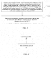
- a modulation processing method for high-order coding is further provided, which can be applied in a terminal. As shown in Fig. 3 , the method includes the following steps.
- a terminal receives the downlink control signaling transmitted by a base station, the downlink control signaling including a modulation and coding scheme field I MCS , herein the I MCS is based on a Modulation and Coding Scheme (MCS) table selected by the base station according to a transmission type and predefined information, herein the MCS table includes a MCS table supporting a M-order modulation and a MCS table not supporting a M-order modulation, herein M>64; and in S304, the terminal implements modulation and coding on uplink data or implements demodulation and decoding on downlink data according to I MCS .
- MCS Modulation and Coding Scheme
- the base station selects a downlink MCS table according to the predefined information, herein the predefined information includes: a table type configured for a subframe set, herein the table type is a Channel Quality Indication (CQI) table supporting a M-order modulation or a CQI table not supporting a M-order modulation.
- the subframe set may include but not limited to: subframe set 0 and/or subframe set 1 configured by the base station.
- the transmission type is downlink transmission and the base station selects a downlink MCS table, at least one of the following steps is included:
- the base station selects an uplink MCS table according to the predefined information, herein the predefined information includes at least one of:
- the DCI format includes but not limited to at least one of DCI format 0 and DCI format 4.
- the base station selects an uplink MCS table according to the table type configured during downlink transmission, when the CQI table supporting a M-order modulation and/or the MCS table supporting a M-order modulation is configured for the downlink transmission, configuring an uplink MCS table supporting a M-order modulation for uplink transmission in a specific scenario; when the CQI table supporting a M-order modulation and/or the MCS table supporting a M-order modulation is configured for the downlink transmission and Channel State Information (CSI) is transmitted on a Physical Uplink Shared Channel (PUSCH) for uplink transmission in a specific scenario, configuring an uplink MCS table not supporting a M-order modulation for the uplink transmission; and selecting an uplink MCS table supporting or not supporting a M-order modulation for the uplink transmission through configuration signaling sent by the base station.
- CSI Channel State Information
- the specific scenario includes but not limited to TDD transmission.
- the MCS table may be selected by at least one of:
- the base station selects the table type to be an uplink MCS table according to a configured or predefined subframe set, at least one of the following is further included: the base station respectively configuring an uplink MCS table supporting or not supporting a M-order modulation for a subframe set 2 and a subframe set 3, the subframe set 2 and the subframe set 3 being uplink subframe sets configured by the base station or predefined subframe sets;
- the method includes at least one of:
- the terminal receives the downlink control signaling transmitted by the base station, at this time the downlink control signaling further including: a Transmission Power Control (TPC) command field, herein the TPC command field includes at least one of the following characteristics: when the downlink control signaling is transmitted through DCI format 3A, the TPC command field is represented by N1 bits, herein N1 is a positive integer not less than 1, and the value of TPC command corresponding to the TPC command field includes but not limited to an integer other than -1 and 1; and when the downlink control signaling is transmitted through a DCI format other than the DCI format 3A, the TPC command field is represented by N2 bits, herein N2 is a positive integer equal to or greater than 2, and the value of TPC command corresponding to the TPC command field includes but not limited to an integer other than -1, 0, 1 and 3.
- TPC Transmission Power Control
- a modulation processing apparatus for high-order coding is further included, which can be applied in a terminal. As shown in Fig. 4 , the apparatus includes:
- the receiving module 40 is further configured to, when the transmission type is downlink transmission, select, by the base station, a downlink MCS table according to the predefined information, and when the predefined information includes the following information, receive I MCS : a table type configured for a subframe set, herein the table type is a MCS table supporting a M-order modulation or a MCS table not supporting a M-order modulation.
- the receiving module 40 is further configured to, when the transmission type is uplink transmission, select, by the base station, a downlink MCS table according to the predefined information, and when the predefined information includes at least one of the following information, receive I MCS :
- a terminal including any modulation processing apparatus for high-order coding described above.
- the conventional table of the communication system can neither support the higher-order modulation, nor can solve the problem of the specific configuration and usage of the enhanced table for the high-order modulation and the conventional table, for example, in which condition, it is to configure the enhanced table for the high-order modulation and in which condition, it is to use the conventional table.
- a base station selects a table supporting a M-order modulation or selects a table not supporting a M-order modulation according to a transmission type and predefined information.
- the transmission type is uplink transmission or downlink transmission.
- the table supporting a M-order modulation is a MCS table supporting a M-order modulation
- the table not supporting a M-order modulation is a MCS table not supporting a M-order modulation, herein M is greater than or equal to 256 and is a positive integer.
- the base station transmits the downlink control signaling, the downlink control signaling at least including a modulation and coding scheme field (IMCS), herein the IMCS is based on the table supporting or not supporting a M-order modulation selected by the base station.
- IMCS modulation and coding scheme field
- a MCS table used for downlink subframe is determined according to a CQI table configured for a predefined subframe set.
- the predefined subframe set includes subframe set 0 and/or subframe set 1 configured by a base station.
- Said determining a MCS table used for downlink subframe according to a CQI table configured for a predefined subframe set includes: using a MCS table supporting 256QAM for all downlink subframes including sub frames that do not belong to configured subframe set 0/1, when a CQI table supporting 256QAM is configured for at least one of the predefined subframe sets.
- the base station transmits the configuration signaling to the terminal, herein the signaling configures subframe set 0 and subframe set 1.
- the base station transmits configuration signaling 1 to the terminal, and the signaling configures a table supporting a 256QAM modulation for the subframe set 0, herein the table supporting 256QAM is a CQI table supporting 256QAM; and it selects a table not supporting 256QAM for the subframe set 1, herein the table not supporting 256QAM is a CQI table of the LTE Rel-11 version standard 36.213.
- the base station transmits the downlink control signaling to the terminal on a downlink subframe.
- the downlink control signaling includes a modulation and coding scheme field (IMCS).
- the terminal receives the downlink control signaling transmitted by the base station, herein the IMCS is based on the MCS table supporting 256QAM.
- the CQI table supporting 256QAM is configured for at least one of the subframe set 0 and the subframe set 1
- a MCS table supporting 256QAM is configured for all the downlink subframes. This simplifies the configuration, and increases the opportunity to exploit high-order modulation, i.e. 256 QAM. It improves the spectral efficiency using 256QAM in a high signal-to-noise ratio condition.
- the base station transmits the configuration signaling to the terminal, herein the signaling configures subframe set 0 and subframe set 1.
- the base station transmits configuration signaling 1 to the terminal, and the signaling configures a table supporting a 256QAM modulation for the subframe set 1, herein the table supporting 256QAM is a CQI table supporting 256QAM; and it selects a table not supporting 256QAM for the subframe set 0, herein the table not supporting 256QAM is a CQI table of the LTE Rel-11 version standard 36.213.
- the base station transmits the downlink control signaling to the terminal on a downlink subframe.
- the downlink control signaling includes a modulation and coding scheme field (IMCS).
- IMCS is based on the MCS table supporting 256QAM.
- a MCS table supporting 256QAM is configured for all the downlink subframes. This simplifies the configuration, and improves the spectral efficiency using 256QAM in a high signal-to-noise ratio condition.
- the base station transmits configuration signaling to the terminal, herein the signaling configures subframe set 0 and subframe set 1.
- the base station transmits configuration signaling 1 to the terminal, and the signaling configures a table supporting a 256QAM modulation for the subframe set 0, herein the table supporting 256QAM is a CQI table supporting 256QAM; and it selects a table not supporting 256QAM for the subframe set 1, herein the table not supporting 256QAM is a CQI table of the LTE Rel-11 version standard 36.213.
- the base station transmits the downlink control signaling to the terminal on the subframe set 0.
- the downlink control signaling includes a modulation and coding scheme field (IMCS), herein the IMCS is based on the MCS table supporting 256QAM.
- the base station transmits the downlink control signaling to the terminal on the subframe set 1 and subframe set 2.
- the downlink control signaling includes a modulation and coding scheme field (IMCS).
- IMCS modulation and coding scheme field
- the IMCS is based on a MCS table not supporting 256QAM.
- the MCS table for the downlink subframe is selected according to the table configured for the subframe set, which better utilizes the signal to interference plus noise ratio condition of the channel to configure the table, and better achieves adaptive modulation and coding, thereby improving the system throughput.
- the base station transmits the configuration signaling to the terminal, herein the signaling configures subframe set 0 and subframe set 1.
- the base station transmits configuration signaling 1 to the terminal, and the signaling configures a table supporting a 256QAM modulation for the subframe set 1, herein the table supporting 256QAM is a CQI table supporting 256QAM; and it selects a table not supporting 256QAM for the subframe set 0, herein the table not supporting 256QAM is a CQI table of the LTE Rel-11 version standard 36.213.
- the base station transmits the downlink control signaling to the terminal on the subframe set 1.
- the downlink control signaling includes a modulation and coding scheme field (IMCS), herein the IMCS is based on the MCS table supporting 256QAM.
- the base station transmits the downlink control signaling to the terminal on the subframe set 0.
- the downlink control signaling includes a modulation and coding scheme field ( I MCS ).
- the IMCS is based on a MCS table not supporting 256QAM.
- the base station transmits configuration signaling 2 to the terminal.
- the signaling configures a MCS table supporting a 256QAM modulation for the subframe set 2.
- the base station transmits the downlink control signaling, on the subframe set 2, to the terminal.
- the downlink control signaling includes a modulation and coding scheme field (IMCS), herein the IMCS is based on the MCS table supporting 256QAM.
- IMCS modulation and coding scheme field
- the MCS table for the downlink subframe is selected according to the table configured for the subframe set, which better utilizes the signal to interference plus noise ratio condition of the channel to configure the table, and better achieves adaptive modulation and coding, thereby improving the system throughput.
- the table is configured by a high layer according to the signal to interference plus noise ratio condition of the channel, which is also used to better achieve adaptive modulation and coding, thereby improving the system throughput.
- the configuration of the uplink MCS table is as follows: 1) determining the use of the uplink MCS table from the type of the configured downlink CQI table and/or MCS table; and 2) configuring the uplink MCS table through independent Radio Resource Control (RRC).
- RRC Radio Resource Control
- the base station transmits configuration signaling 0 to the terminal, herein the configuration signaling 0 selects an enhanced table supporting or not supporting 256QAM for downlink transmission.
- the enhanced table supporting 256QAM is a CQI table or MCS table supporting 256QAM.
- the enhanced table not supporting 256QAM is a CQI table and/or MCS table not supporting 256QAM.
- the base station transmits configuration signaling 1 to the terminal, and the configuration signaling 1 selects the enhanced table supporting 256QAM for uplink transmission.
- the enhanced table supporting 256QAM is a MCS table supporting 256QAM.
- the base station transmits the downlink control signaling to the terminal through DCI format 0 or DCI format 4.
- the downlink control signaling includes a modulation and coding scheme field (IMCS).
- IMCS modulation and coding scheme field
- the base station receives, on a PUSCH, uplink data which does not include a CSI transmitted by the terminal, herein the IMCS is based on a MCS table supporting 256QAM.
- the selections of the uplink table and the downlink table are independent, which can better utilize the signal to interference plus noise ratio condition of the channel to configure the table, and better achieves adaptive modulation and coding, thereby improving the system throughput.
- the base station transmits configuration signaling 0 to the terminal, herein the configuration signaling 0 selects an enhanced table supporting or not supporting 256QAM for downlink transmission.
- the enhanced table supporting 256QAM is a CQI table or MCS table supporting 256QAM.
- the enhanced table not supporting 256QAM is a CQI table and/or MCS table not supporting 256QAM.
- the base station transmits configuration signaling 1 to the terminal, and the configuration signaling 1 selects the enhanced table supporting 256QAM for uplink transmission.
- the enhanced table supporting 256QAM is a MCS table supporting 256QAM.
- the base station transmits the downlink control signaling to the terminal through DCI format 0 or DCI format 4.
- the downlink control signaling includes a modulation and coding scheme field (IMCS).
- the base station receives, on a PUSCH, CSI data transmitted by the terminal, herein the I MCS is based on a MCS table not supporting 256QAM.
- the selections of the uplink table and the downlink table are independent, which can better utilize the signal to interference plus noise ratio condition of the channel to configure the table, and better achieves adaptive modulation and coding, thereby improving the system throughput.
- For the condition of transmission of the CSI data on the PUSCH it should try to use a low-order modulation to ensure the accuracy of the transmission. Therefore, there is no need to use the MCS table supporting 256QAM.
- the MCS table not supporting 256QAM may have finer granularity of the spectral efficiency in an area with low spectral efficiency, which can better achieve adaptive modulation and coding.
- Sub-Embodiment three in this embodiment, a specific scenario is assumed.
- This specific scenario includes a TDD scenario.
- Two nodes i.e., node 1 and node 2, transmit downlink data to the terminal.
- a downlink enhanced table supporting 256QAM is configured for the node 1.
- a downlink enhanced table not supporting 256QAM is configured for the node 2.
- the downlink enhanced table supporting 256QAM is a CQI table or MCS table supporting 256QAM.
- the downlink enhanced table not supporting 256QAM is a CQI table and/or MCS table not supporting 256QAM.
- the node 1 or node 2 transmits the downlink control signaling to the terminal through DCI format 0 or DCI format 4.
- the downlink control signaling includes a modulation and coding scheme field (IMCS).
- IMCS modulation and coding scheme field
- the nodes 1 and 2 receive, on a PUSCH, uplink data which does not include a CSI transmitted by the terminal, herein the IMCS is based on a MCS table supporting 256QAM.
- the table is configured for the uplink according to the downlink table, which considers channel reciprocity in the specific scenario, thereby simplifying the configuration of the table.
- Sub-Embodiment four in this embodiment, a specific scenario is assumed.
- This specific scenario includes a TDD scenario.
- Two nodes i.e., node 1 and node 2, transmit downlink data to the terminal.
- a downlink enhanced table supporting 256QAM is configured for the node 1.
- a downlink enhanced table not supporting 256QAM is configured for the node 2.
- the downlink enhanced table supporting 256QAM is a CQI table or MCS table supporting 256QAM.
- the downlink enhanced table not supporting 256QAM is a CQI table and/or MCS table not supporting 256QAM.
- the node 1 or node 2 transmits the downlink control signaling to the terminal through DCI format 0 or DCI format 4.
- the downlink control signaling includes a modulation and coding scheme field ( I MCS ).
- the nodes 1 and 2 receive, on a PUSCH, uplink data which includes a CSI transmitted by the terminal, herein the IMCS is based on a MCS table not supporting 256QAM.
- the IMCS is based on a MCS table not supporting 256QAM.
- the MCS table not supporting 256QAM may have the finer granularity of the spectral efficiency in an area with low spectral efficiency, which can better achieve adaptive modulation and coding.
- an uplink MCS table supporting or not supporting 256QAM is determined according to a DCI format, a search space, a CRC scrambling mode, or an uplink transmission mode.
- Sub-Embodiment one in this embodiment, it is assumed that the base station configures uplink transmission mode 1 for the terminal, or only configures a format of DCI format 0 for the terminal.
- the base station transmits the downlink control signaling to the terminal through the DCI format 0 and a common search space, herein the downlink control signaling includes a modulation and coding scheme field (IMCS), which is based on a MCS table not supporting 256QAM.
- IMCS modulation and coding scheme field
- the base station receives, on the PUSCH, uplink data transmitted by the terminal. This configuration results from the use of 256QAM being directed to a particular UE.
- Sub-Embodiment two in this embodiment, it is assumed that the base station configures uplink transmission mode 1 for the terminal, or only configures a format of DCI format 0 for the terminal.
- the base station transmits the downlink control signaling to the terminal through the DCI format 0 and a UE-specific search space, herein the downlink control signaling includes a modulation and coding scheme field (IMCS), which is based on a MCS table supporting 256QAM.
- IMCS modulation and coding scheme field
- the base station receives, on the PUSCH, uplink data transmitted by the terminal. This configuration results from the use of 256QAM being directed to a particular UE.
- Sub-Embodiment three in this embodiment, it is assumed that the base station configures uplink transmission mode 1 for the terminal, or only configures a format of DCI format 0 for the terminal.
- the base station transmits the downlink control signaling to the terminal through the DCI format 0, herein the downlink control signaling includes a modulation and coding scheme field (IMCS), and CRC corresponding to the downlink control signaling is scrambled through a SPS C-RNTI.
- the IMCS is based on a MCS table not supporting 256QAM.
- the base station receives, on the PUSCH, uplink data transmitted by the terminal. This configuration is obtained because the use of 256QAM should be flexibly configured according to a signal to interference plus noise ratio condition.
- Sub-Embodiment four in this embodiment, it is assumed that the base station configures uplink transmission mode 1 for the terminal, or only configures a format of DCI format 0 for the terminal.
- the base station transmits the downlink control signaling to the terminal through the DCI format 0, herein the downlink control signaling includes a modulation and coding scheme field (IMCS), and CRC corresponding to the downlink control signaling is scrambled through a C-RNTI.
- the IMCS is based on a MCS table supporting 256QAM.
- the base station receives, on the PUSCH, uplink data transmitted by the terminal. This configuration is obtained because the use of 256QAM should be flexibly configured according to a signal to interference plus noise ratio condition.
- Sub-Embodiment five in this embodiment, it is assumed that the base station configures uplink transmission mode 1 for the terminal, or only configures a format of DCI format 0 for the terminal.
- the base station transmits the downlink control signaling to the terminal through the DCI format 0 and a UE-specific search space, herein the downlink control signaling includes a modulation and coding scheme field ( I MCS ), and CRC corresponding to the downlink control signaling is scrambled through a SPS C-RNTI.
- the IMCS is based on a MCS table not supporting 256QAM.
- the base station receives, on the PUSCH, uplink data transmitted by the terminal. This configuration is obtained because the use of 256QAM is directed to a particular UE and the use of 256QAM should be flexibly configured according to a signal to interference plus noise ratio condition.
- Sub-Embodiment six in this embodiment, it is assumed that the base station configures uplink transmission mode 1 for the terminal, or only configures a format of DCI format 0 for the terminal.
- the base station transmits the downlink control signaling to the terminal through the DCI format 0 and a UE-specific search space, herein the downlink control signaling includes a modulation and coding scheme field ( I MCS ), and CRC corresponding to the downlink control signaling is scrambled through a C-RNTI.
- the I MCS is based on a MCS table supporting 256QAM.
- the base station receives, on the PUSCH, uplink data transmitted by the terminal. This configuration is obtained because the use of 256QAM is directed to a particular UE and the use of 256QAM should be flexibly configured according to a signal to interference plus noise ratio condition.
- Sub-Embodiment seven in this embodiment, it is assumed that the base station configures uplink transmission mode 2 for the terminal, or configures two formats, i.e., DCI format 0/4 for the terminal.
- the base station transmits the downlink control signaling to the terminal through the DCI format 0, herein the downlink control signaling includes a modulation and coding scheme field ( I MCS ).
- the I MCS is based on a MCS table not supporting 256QAM.
- the base station transmits the downlink control signaling to the terminal through the DCI format 4, herein the downlink control signaling includes a modulation and coding scheme field ( I MCS ).
- the I MCS is based on a MCS table supporting 256QAM.
- the base station receives, on the PUSCH, uplink data transmitted by the terminal.
- the DCI format 4 is used for transmission of multiple code words, and it may correspond to a higher signal to interference plus noise ratio. Therefore, the corresponding uplink transmission may be more likely to use 256QAM.
- Sub-Embodiment eight in this embodiment, it is assumed that the base station configures the uplink transmission mode 2 for the terminal, or configures two formats, i.e., DCI format 0/4 for the terminal.
- the base station transmits the downlink control signaling to the terminal through the DCI format 0 and a common search space and the downlink control signaling includes a modulation and coding scheme field ( I MCS ), the I MCS is based on a MCS table not supporting 256QAM.
- I MCS modulation and coding scheme field
- the I MCS is based on a MCS table supporting 256QAM.
- the base station transmits the downlink control signaling to the terminal through the DCI format 4 and the downlink control signaling includes a modulation and coding scheme field ( I MCS )
- the IMCS is based on a MCS table supporting 256QAM.
- the base station receives, on the PUSCH, uplink data transmitted by the terminal.
- a table supporting 256QAM is also configured, which provides possibility to use 256QAM. This considers that it should try to use 256QAM to improve the spectral efficiency. Further, the use of 256QAM is directed to a particular UE.
- Sub-Embodiment nine in this embodiment, it is assumed that the base station configures uplink transmission mode 2 for the terminal, or configures two formats, i.e., DCI format 0/4 for the terminal.
- the downlink control signaling includes a modulation and coding scheme field ( I MCS ) and CRC corresponding to the downlink control signaling is scrambled through a SPS C-RNTI, the I MCS is based on a MCS table not supporting 256QAM.
- I MCS modulation and coding scheme field
- the downlink control signaling includes a modulation and coding scheme field ( I MCS ) and the CRC corresponding to the downlink control signaling is scrambled through a C-RNTI, the I MCS is based on a MCS table supporting 256QAM.
- the base station transmits the downlink control signaling to the terminal through the DCI format 4 and the downlink control signaling includes a modulation and coding scheme field ( I MCS )
- the I MCS is based on a MCS table supporting 256QAM.
- the base station receives, on the PUSCH, uplink data transmitted by the terminal.
- a table supporting 256QAM is also configured, which provides possibility to use 256QAM. This considers that it should try to use 256QAM to improve the spectral efficiency. Further, the use of 256QAM should be flexibly configured according to a signal to interference plus noise ratio condition.
- Sub-Embodiment ten in this embodiment, it is assumed that the base station configures the uplink transmission mode 2 for the terminal, or configures two formats, i.e., DCI format 0/4 for the terminal.
- the base station transmits the downlink control signaling to the terminal through the DCI format 0 and a common search space and the downlink control signaling includes a modulation and coding scheme field ( I MCS ), the I MCS is based on a MCS table not supporting 256QAM.
- I MCS modulation and coding scheme field
- the downlink control signaling includes a modulation and coding scheme field ( I MCS ), and a CRC corresponding to the downlink control signaling is scrambled through a C-RNTI
- I MCS modulation and coding scheme field
- the IMCS is based on a MCS table supporting 256QAM.
- the downlink control signaling includes a modulation and coding scheme field ( I MCS ) and the CRC corresponding to the downlink control signaling is scrambled through a SPS-C-RNTI, the I MCS is based on a MCS table not supporting 256QAM.
- the base station transmits the downlink control signaling to the terminal through the DCI format 4 and the downlink control signaling includes a modulation and coding scheme field ( I MCS )
- the I MCS is based on a MCS table supporting 256QAM.
- the base station receives, on the PUSCH, uplink data transmitted by the terminal.
- a table supporting 256QAM is also configured, which provides possibility to use 256QAM. This considers that it should try to use 256QAM to improve the spectral efficiency. Further, the use of 256QAM is directed to a particular UE, and the use of 256QAM should be flexibly configured according to a signal to interference plus noise ratio condition.
- a mapping relationship from a TPC command field in a DCI format 0/3/3A/4 to a TPC command is designed.
- power control of Release 11 version LTE protocol 36.213 is directed to 64QAM and a lower-order modulation.
- Design of a new mapping relationship considers that a higher signal to interference plus noise ratio condition is needed for 256QAM. A higher signal to interference plus noise ratio can be provided through uplink power control.
- the base station transmits the configuration signaling to the terminal, herein the signaling configures a MCS table supporting 256QAM for uplink transmission.
- the base station transmits the downlink control signaling to the terminal through the DCI format 0 or the DCI format 4 or the DCI format 3, herein the downlink control signaling includes a TPC command field.
- the value of the TPC command field is 0, 1, 2 or 3.
- Table 1 A mapping relationship from the TPC command field to an absolute and accumulated TPC command is as shown in Table 1: Table 1: Mapping from a TPC command field in the DCI format 0/3/4 to an absolute and accumulated ⁇ PUSCH,c value TPC Command Field in Accumulated ⁇ PUSCH,c [dB] Absolute ⁇ PUSCH,c [dB] only DCI format 0/4 DCI format 0/3/4 0 -1 -5 1 0 -2 2 1.5 2 3 3.5 5
- the base station transmits the configuration signaling to the terminal, herein the signaling configures a MCS table supporting 256QAM for uplink transmission.
- the base station transmits the downlink control signaling to the terminal through the DCI format 0 or the DCI format 4 or the DCI format 3, herein the downlink control signaling includes a TPC command field.
- the value of the TPC command field is 0, 1, 2 ... or 7.
- Table 2 Mapping from a TPC command field in the DCI format 0/3/4 to an absolute and accumulated ⁇ PUSCH,c value TPC Command Field in Accumulated ⁇ PUSCH,c [dB] Absolute ⁇ PUSCH,c [dB] only DCI format 0/4 DCI format 0/3/4 0 -1 -4 1 0 -1 2 1 1 3 3 4 4 4 -5 5 -2 5 6 - 7 Reserved
- Sub-Embodiment three in this embodiment, the base station transmits the configuration signaling to the terminal, herein the signaling configures a MCS table supporting 256QAM for uplink transmission.
- the base station transmits the downlink control signaling to the terminal through the DCI format 3A, herein the downlink control signaling includes a TPC command field.
- the value of the TPC command field is 0 or 1.
- a mapping relationship from the TPC command field to an accumulated TPC command is as shown in the following table: Table 3: Mapping from a TPC command field in the DCI format 3A to an accumulated ⁇ PUSCH,c value TPC Command Field in Accumulated ⁇ PUSCH,c [dB] DCI format 3A 0 -1.5 1.5 1.5
- the base station transmits the configuration signaling to the terminal, herein the signaling configures a MCS table supporting 256QAM for uplink transmission.
- the base station transmits the downlink control signaling to the terminal through the DCI format 3A, herein the downlink control signaling includes a TPC command field.
- the value of the TPC command field is 0, 1, 2 or 3.
- a mapping relationship from the TPC command field to an accumulated TPC command is as shown in the following table: Table 4: Mapping from a TPC command field in the DCI format 3A to an accumulated ⁇ PUSCH,c value TPC Command Field in Accumulated ⁇ PUSCH,c [dB] DCI format 3A 0 -1 1 1 2 -2 3 2
- Uplink MCS Table supporting 256QAM is designed.
- an uplink MCS table of the Release 11 version LTE protocol 36.213 supports at most 64QAM, and does not support 256QAM.
- the base station transmits the configuration signaling to the terminal, herein the signaling configures a MCS table supporting 256QAM for uplink transmission.
- the base station transmits the downlink control signaling to the terminal through DCI format 0 or DCI format 4, herein the downlink control signaling includes a modulation and coding scheme field ( I MCS ).
- the IMCS is based on a PUSCH modulation, TBS index and redundancy version table as follows.
- the base station transmits the configuration signaling to the terminal, herein the signaling configures a MCS table supporting 256QAM for uplink transmission.
- the base station transmits the downlink control signaling to the terminal through DCI format 0 or DCI format 4, herein the downlink control signaling includes a modulation and coding scheme field ( I MCS ).
- the IMCS is based on a PUSCH modulation, TBS index and redundancy version table as follows.
- the base station transmits the configuration signaling to the terminal, herein the signaling configures a MCS table supporting 256QAM for uplink transmission.
- the base station transmits the downlink control signaling to the terminal through DCI format 0 or DCI format 4, herein the downlink control signaling includes a modulation and coding scheme field ( I MCS ).
- the IMCS is based on a PUSCH modulation, TBS index and redundancy version table as follows.
- the modulation processing apparatus for high-order coding according to the embodiments of the present invention can be combined with the modulation processing method for high-order coding according to the embodiments of the present invention.
- the base station selects a table supporting a M-order modulation or a table not supporting a M-order modulation according to a transmission type and predefined information.
- the transmission type is uplink transmission or downlink transmission.
- the table supporting a M-order modulation is a MCS table supporting a M-order modulation
- the table not supporting a M-order modulation is a MCS table not supporting a M-order modulation, herein M ⁇ 256 and it is a positive integer.
- the base station transmits downlink control information including at least a modulation and coding scheme field ( I MCS ), herein the I MCS is based on the table supporting or not supporting a M-order modulation selected by the base station.
- I MCS modulation and coding scheme field
- supporting or not supporting the use of the M-order modulation is flexibly configured according to a signal to interference plus noise ratio condition, which supports the high-order modulation on the basis of compatibility with the existing wireless transmission network, can better realize the adaptive modulation and coding while ensuring accuracy of transmission, thereby improving the system peak rate and the spectral efficiency; and the configuration should be simplified as much as possible, thereby reducing the complexity of the table configuration.
- M is greater than or equal to 256
- M provides an appropriate signal to interference plus noise ratio condition for the use of the M-order modulation.
- M is greater than or equal to 256
- This can well support the use of the M-order modulation, trade off the relationship between the improvement of the spectrum efficiency and the guarantee of the accuracy of the transmission, thereby simplifying the configuration and improving the peak data transmission rate and throughput of the wireless communication system.
- a storage medium having the above-described software stored therein, including, but not limited to, an optical disk, a floppy disk, a hard disk, a rewritable memory etc.
- each module or each step of the aforementioned present invention can be implemented with general computing apparatuses, and they can be integrated in a single computing apparatus, or distributed in a network composed of a plurality of computing apparatuses; alternatively, they can be implemented with program codes executable by the computing apparatuses, and therefore, they can be stored in storage apparatuses to be executed by the computing apparatuses; in some cases, the steps illustrated or described can be performed in an order different from that described here; alternatively, they are respectively made into a plurality of integrated circuit modules; and alternatively, it is implemented with making several modules or steps of them into a single integrated circuit module.
- the present invention is not limited to any specific combinations of hardware and software.
- a technical measure of the base station selecting a MCS table according to a transmission type and predefined information and transmitting I MCS based on the MCS table selected by the base station is used to solve the technical problem in the related art that the conventional table cannot support a higher-order modulation, thereby achieving the transmission between the base station and the terminal based on the higher-order modulation.
Landscapes
- Engineering & Computer Science (AREA)
- Computer Networks & Wireless Communication (AREA)
- Signal Processing (AREA)
- Quality & Reliability (AREA)
- Physics & Mathematics (AREA)
- Spectroscopy & Molecular Physics (AREA)
- Power Engineering (AREA)
- Multimedia (AREA)
- Electromagnetism (AREA)
- Mobile Radio Communication Systems (AREA)
Applications Claiming Priority (2)
| Application Number | Priority Date | Filing Date | Title |
|---|---|---|---|
| CN201410197177.5A CN104202115B (zh) | 2014-05-09 | 2014-05-09 | 高阶编码的调制处理方法及装置、基站、终端 |
| PCT/CN2014/085689 WO2015169013A1 (zh) | 2014-05-09 | 2014-09-01 | 高阶编码的调制处理方法及装置、基站、终端 |
Publications (3)
| Publication Number | Publication Date |
|---|---|
| EP3142278A1 EP3142278A1 (en) | 2017-03-15 |
| EP3142278A4 EP3142278A4 (en) | 2017-05-17 |
| EP3142278B1 true EP3142278B1 (en) | 2019-08-07 |
Family
ID=52087353
Family Applications (1)
| Application Number | Title | Priority Date | Filing Date |
|---|---|---|---|
| EP14891460.9A Active EP3142278B1 (en) | 2014-05-09 | 2014-09-01 | Modulation processing method and apparatus for high-order coding, base station, and terminal |
Country Status (9)
| Country | Link |
|---|---|
| US (1) | US10050819B2 (https=) |
| EP (1) | EP3142278B1 (https=) |
| JP (1) | JP6489584B2 (https=) |
| KR (1) | KR101891131B1 (https=) |
| CN (1) | CN104202115B (https=) |
| AU (1) | AU2014393144B2 (https=) |
| BR (1) | BR112016026160B1 (https=) |
| RU (1) | RU2645295C1 (https=) |
| WO (1) | WO2015169013A1 (https=) |
Families Citing this family (32)
| Publication number | Priority date | Publication date | Assignee | Title |
|---|---|---|---|---|
| US9722848B2 (en) * | 2014-05-08 | 2017-08-01 | Intel Corporation | Techniques for using a modulation and coding scheme for downlink transmissions |
| EP3404859B1 (en) * | 2016-01-13 | 2020-12-02 | LG Electronics Inc. -1- | Method and device for transmitting/receiving wireless signals in wireless communication system |
| CN108496408B (zh) * | 2016-01-26 | 2023-10-20 | 株式会社Ntt都科摩 | 基站及发送方法 |
| KR102280055B1 (ko) * | 2016-04-01 | 2021-07-21 | 텔레호낙티에볼라게트 엘엠 에릭슨(피유비엘) | 업링크 256qam을 위한 상이한 서브프레임 세트들의 핸들링 |
| CN113890686B (zh) * | 2016-05-13 | 2023-05-02 | 中兴通讯股份有限公司 | 极化码处理方法及装置、节点 |
| CN108023709B (zh) * | 2016-11-04 | 2022-03-15 | 夏普株式会社 | 上行发送波形的配置方法、基站和用户设备 |
| US20220110160A1 (en) * | 2016-12-27 | 2022-04-07 | Ntt Docomo, Inc. | User terminal and radio communication method |
| WO2018137204A1 (zh) | 2017-01-25 | 2018-08-02 | 华为技术有限公司 | 外环链路自适应的调整方法和装置 |
| US10958489B2 (en) * | 2017-03-21 | 2021-03-23 | Samsung Electronics Co., Ltd. | Method and apparatus for wireless communication using modulation, coding schemes, and channel quality indicators |
| CN107223317B (zh) * | 2017-04-24 | 2020-01-14 | 北京小米移动软件有限公司 | 确定调制编码方式的方法及装置 |
| US10938504B2 (en) | 2017-05-05 | 2021-03-02 | Qualcomm Incorporated | Enhancements to modulation order determination |
| US11246116B2 (en) * | 2017-06-16 | 2022-02-08 | Qualcomm Incorporated | Multiple MCS tables for NR |
| WO2019024085A1 (zh) * | 2017-08-04 | 2019-02-07 | 华为技术有限公司 | 调制编码方式确定方法、装置及系统 |
| EP3462654B8 (en) * | 2017-09-28 | 2021-01-20 | Apple Inc. | Apparatus for supporting 1024 quadrature amplitude modulation |
| CN109600200B (zh) * | 2017-09-30 | 2020-10-30 | 维沃移动通信有限公司 | 一种传输方法、移动通信终端及网络侧设备 |
| CN109963348A (zh) * | 2017-12-26 | 2019-07-02 | 电信科学技术研究院 | 一种csi调制阶数的确定方法、终端及基站 |
| KR20190085820A (ko) * | 2018-01-11 | 2019-07-19 | 주식회사 케이티 | 차세대 무선망을 위한 데이터 변조 및 부호화 방법 및 장치 |
| EP4572451A3 (en) | 2018-01-11 | 2026-01-07 | KT Corporation | Method and apparatus for data modulation and coding for new radio |
| CN110034859B (zh) | 2018-01-12 | 2021-06-08 | 华为技术有限公司 | 一种通信方法及设备 |
| US10708112B2 (en) | 2018-01-12 | 2020-07-07 | At&T Intellectual Property I, L.P. | Dynamic indication of higher order modulation and coding scheme table |
| US10567108B2 (en) | 2018-02-16 | 2020-02-18 | At&T Intellectual Property I, L.P. | Adaptive configuration of modulation and coding scheme tables for new radio |
| CN111510254B (zh) * | 2018-02-23 | 2022-07-12 | Oppo广东移动通信有限公司 | 动态配置方法、终端设备、网络设备及计算机存储介质 |
| CN110474739B (zh) * | 2018-05-11 | 2022-06-28 | 中兴通讯股份有限公司 | 调制编码及cqi上报方法、装置、设备及存储介质 |
| CN110474732B (zh) * | 2018-05-11 | 2022-05-10 | 大唐移动通信设备有限公司 | 一种调制与编码策略mcs表格的指示方法、装置及基站 |
| CN110475354B (zh) * | 2018-05-11 | 2025-04-01 | 中兴通讯股份有限公司 | 控制信息的发送,接收方法及装置、通信系统 |
| US10980044B2 (en) | 2018-07-13 | 2021-04-13 | Qualcomm Incorporated | Rate matching and semi persistent scheduling configuration in wireless communications |
| CN112470517A (zh) * | 2018-07-20 | 2021-03-09 | 夏普株式会社 | 用于csi报告的用户设备、基站和方法 |
| US20200053835A1 (en) * | 2018-08-08 | 2020-02-13 | Idac Holdings, Inc. | Uu interface enhancement for nr v2x |
| US11528086B2 (en) * | 2019-06-20 | 2022-12-13 | Qualcomm Incorporated | Link configuration specific modulation and coding scheme (MCS) |
| WO2021159374A1 (zh) | 2020-02-13 | 2021-08-19 | 北京小米移动软件有限公司 | 通信方法、通信装置及存储介质 |
| WO2022052005A1 (zh) * | 2020-09-10 | 2022-03-17 | 北京小米移动软件有限公司 | 一种调制编码mcs表格配置方法、装置及存储介质 |
| CN116939857A (zh) * | 2022-03-31 | 2023-10-24 | 上海华为技术有限公司 | 终端调度方法、装置、基站及介质 |
Family Cites Families (35)
| Publication number | Priority date | Publication date | Assignee | Title |
|---|---|---|---|---|
| US6741575B1 (en) | 1999-02-26 | 2004-05-25 | Hughes Electronics Corporation | Apparatus and method for efficient delivery of multicast data over personal access communications system (PACS) |
| KR100450948B1 (ko) * | 2001-07-12 | 2004-10-02 | 삼성전자주식회사 | 통신시스템에서 변조방식 결정장치 및 방법 |
| KR100800807B1 (ko) * | 2001-11-20 | 2008-02-01 | 삼성전자주식회사 | 재전송을 지원하는 통신시스템에서 재전송의 변조방식결정 방법 및 장치 |
| EP1534039B1 (en) * | 2003-11-19 | 2013-01-16 | Samsung Electronics Co., Ltd. | Apparatus and method for transmitting and receiving common control information in a wireless communication system |
| KR100898343B1 (ko) | 2006-12-01 | 2009-05-20 | 한국전자통신연구원 | Iptv 서비스를 위한 채널 제어 방법 및 그의 장치 |
| US7933238B2 (en) * | 2007-03-07 | 2011-04-26 | Motorola Mobility, Inc. | Method and apparatus for transmission within a multi-carrier communication system |
| CA2710517C (en) * | 2007-12-26 | 2015-10-13 | Research In Motion Limited | System and method modulation scheme changes |
| US8179783B2 (en) * | 2008-08-13 | 2012-05-15 | Telefonaktiebolaget L M Ericsson (Publ) | System and method of modulation and coding scheme adjustment for a LTE shared data channel |
| US9107208B2 (en) * | 2010-05-12 | 2015-08-11 | Lg Electronics Inc. | Method for transmitting an SRS-triggering-based SRS in a wireless communication system |
| CN102595600B (zh) * | 2011-01-17 | 2014-12-31 | 华为技术有限公司 | 半静态调度方法、用户设备及网络设备 |
| CN102624481A (zh) * | 2011-01-31 | 2012-08-01 | 中兴通讯股份有限公司 | 自适应调制编码方法及装置 |
| CN102088789B (zh) * | 2011-03-03 | 2013-04-17 | 北京航空航天大学 | 用于无线通信的信道信息反馈自适应传输和带宽分配方法 |
| JP5990815B2 (ja) * | 2011-11-07 | 2016-09-14 | シャープ株式会社 | 基地局、端末、通信システムおよび通信方法 |
| PL4191913T3 (pl) * | 2012-02-20 | 2025-01-07 | Nokia Technologies Oy | Sterowanie schematem modulacji i kodowania dla transmisji między stacją bazową a urządzeniem użytkownika |
| CN103391563B (zh) * | 2012-05-11 | 2018-06-08 | 中兴通讯股份有限公司 | 下行控制信息发送方法、检测方法、基站及用户设备 |
| US9794817B2 (en) * | 2012-06-24 | 2017-10-17 | Lg Electronics Inc. | Method and apparatus for reporting channel state information in wireless communication system |
| CN103580788A (zh) * | 2012-07-27 | 2014-02-12 | 电信科学技术研究院 | 一种传输mcs指示信息的方法及装置 |
| EP2888827B1 (en) | 2012-08-24 | 2021-02-17 | Sun Patent Trust | Communication method, base station and user equipment |
| KR102086515B1 (ko) * | 2012-09-16 | 2020-03-09 | 엘지전자 주식회사 | 무선 통신 시스템에서 안테나 포트 관계를 고려한 하향링크 신호 송수신 방법 및 장치 |
| WO2014046458A1 (ko) * | 2012-09-20 | 2014-03-27 | 엘지전자 주식회사 | 무선 통신 시스템에서 안테나 포트 관계를 고려한 하향링크 신호 송수신 방법 및 장치 |
| CN104823177B (zh) | 2012-09-28 | 2018-02-06 | 黑莓有限公司 | 用于在lte异构网络中实现进一步l1增强的方法和装置 |
| US9419772B2 (en) * | 2012-12-17 | 2016-08-16 | Lg Electronics Inc. | Method and apparatus for transmitting and receiving MCS index for 256QAM in wireless access system |
| US9306778B2 (en) * | 2013-09-02 | 2016-04-05 | Telefonaktiebolaget L M Ericsson (Publ) | Enabling modulation mode selection |
| KR20160051758A (ko) * | 2013-09-03 | 2016-05-11 | 삼성전자주식회사 | 다운링크 전송 방법 및 사용자 단말 장치 |
| JP6456961B2 (ja) * | 2013-09-16 | 2019-01-23 | エルジー エレクトロニクス インコーポレイティド | 無線通信システムにおいて上りリンクデータ受信のための複数ポイント協調方法及びこれを行う装置 |
| US9743432B2 (en) * | 2013-09-23 | 2017-08-22 | Qualcomm Incorporated | LTE-U uplink waveform and variable multi-subframe scheduling |
| US10757726B2 (en) * | 2013-12-27 | 2020-08-25 | Sharp Kabushiki Kaisha | Terminal device, base station device, and communication method using channel quality indicator (CQI) tables and modulation coding scheme (MCS) tables to determine modulation scheme |
| JPWO2015099173A1 (ja) * | 2013-12-27 | 2017-03-23 | シャープ株式会社 | 端末装置および基地局装置 |
| US9467269B2 (en) * | 2014-01-06 | 2016-10-11 | Intel IP Corporation | Systems and methods for modulation and coding scheme selection and configuration |
| WO2015141688A1 (ja) * | 2014-03-20 | 2015-09-24 | シャープ株式会社 | 端末装置および基地局装置 |
| KR101842204B1 (ko) * | 2014-03-28 | 2018-03-26 | 엘지전자 주식회사 | 무선접속 시스템에서 256qam 지원을 위한 채널상태정보 보고 방법 및 장치 |
| US10405285B2 (en) * | 2014-04-20 | 2019-09-03 | Lg Electronics Inc. | Method for determining transmit power for direct device to device communication in wireless communication system and apparatus therefor |
| US10075309B2 (en) * | 2014-04-25 | 2018-09-11 | Qualcomm Incorporated | Modulation coding scheme (MCS) indication in LTE uplink |
| EP3611890B1 (en) * | 2014-07-29 | 2022-04-06 | Telefonaktiebolaget LM Ericsson (publ) | Signaling of modulation configuration |
| US9794922B2 (en) * | 2014-09-26 | 2017-10-17 | Qualcomm Incorporated | Downlink channel design for LTE with low latency |
-
2014
- 2014-05-09 CN CN201410197177.5A patent/CN104202115B/zh active Active
- 2014-09-01 KR KR1020167034401A patent/KR101891131B1/ko active Active
- 2014-09-01 WO PCT/CN2014/085689 patent/WO2015169013A1/zh not_active Ceased
- 2014-09-01 BR BR112016026160-7A patent/BR112016026160B1/pt active IP Right Grant
- 2014-09-01 EP EP14891460.9A patent/EP3142278B1/en active Active
- 2014-09-01 US US15/309,804 patent/US10050819B2/en active Active
- 2014-09-01 JP JP2016567204A patent/JP6489584B2/ja active Active
- 2014-09-01 AU AU2014393144A patent/AU2014393144B2/en active Active
- 2014-09-01 RU RU2016144661A patent/RU2645295C1/ru active
Non-Patent Citations (1)
| Title |
|---|
| None * |
Also Published As
| Publication number | Publication date |
|---|---|
| AU2014393144A1 (en) | 2016-12-22 |
| RU2645295C1 (ru) | 2018-02-19 |
| JP2017520964A (ja) | 2017-07-27 |
| WO2015169013A1 (zh) | 2015-11-12 |
| JP6489584B2 (ja) | 2019-03-27 |
| BR112016026160A2 (https=) | 2017-08-15 |
| AU2014393144B2 (en) | 2018-03-01 |
| US10050819B2 (en) | 2018-08-14 |
| CN104202115A (zh) | 2014-12-10 |
| US20170171014A1 (en) | 2017-06-15 |
| EP3142278A1 (en) | 2017-03-15 |
| EP3142278A4 (en) | 2017-05-17 |
| KR20170005071A (ko) | 2017-01-11 |
| CN104202115B (zh) | 2019-05-07 |
| KR101891131B1 (ko) | 2018-08-24 |
| BR112016026160B1 (pt) | 2023-02-23 |
Similar Documents
| Publication | Publication Date | Title |
|---|---|---|
| EP3142278B1 (en) | Modulation processing method and apparatus for high-order coding, base station, and terminal | |
| US11101962B2 (en) | Communicating a transport block in a wireless network | |
| US10742383B2 (en) | System and method for link adaptation for low cost user equipments | |
| KR101854346B1 (ko) | 무선 통신 시스템의 다운링크 제어 채널을 통해 데이터 정보 메시지를 전송하기 위한 시스템 및 방법 | |
| CN110352578B (zh) | 下行链路控制信道的传输结构和格式 | |
| US20170078830A1 (en) | Methods and Apparatus for Resource Allocation | |
| EP3499758B1 (en) | Transmitting method and device and receiving method and device for transport block | |
| KR102791665B1 (ko) | 단말기 장치, 기지국 장치 및 통신 방법 | |
| CN104753633A (zh) | 高阶编码处理方法、装置和系统 | |
| CN106713192A (zh) | 一种多用户数据传输方法和设备 | |
| CN106160932A (zh) | 信道状态信息上报的方法、用户终端、基站及系统 | |
| HK1229556B (en) | Modulation processing method and apparatus for high-order coding, base station, and terminal | |
| HK1229556A1 (en) | Modulation processing method and apparatus for high-order coding, base station, and terminal | |
| KR20250130160A (ko) | 통신 시스템 또는 방송 시스템에서 제어 정보의 유효성 검사를 위한 전자 장치 및 방법 |
Legal Events
| Date | Code | Title | Description |
|---|---|---|---|
| STAA | Information on the status of an ep patent application or granted ep patent |
Free format text: STATUS: THE INTERNATIONAL PUBLICATION HAS BEEN MADE |
|
| PUAI | Public reference made under article 153(3) epc to a published international application that has entered the european phase |
Free format text: ORIGINAL CODE: 0009012 |
|
| STAA | Information on the status of an ep patent application or granted ep patent |
Free format text: STATUS: REQUEST FOR EXAMINATION WAS MADE |
|
| 17P | Request for examination filed |
Effective date: 20161206 |
|
| AK | Designated contracting states |
Kind code of ref document: A1 Designated state(s): AL AT BE BG CH CY CZ DE DK EE ES FI FR GB GR HR HU IE IS IT LI LT LU LV MC MK MT NL NO PL PT RO RS SE SI SK SM TR |
|
| AX | Request for extension of the european patent |
Extension state: BA ME |
|
| A4 | Supplementary search report drawn up and despatched |
Effective date: 20170419 |
|
| RIC1 | Information provided on ipc code assigned before grant |
Ipc: H04L 1/00 20060101AFI20170411BHEP |
|
| DAX | Request for extension of the european patent (deleted) | ||
| REG | Reference to a national code |
Ref country code: HK Ref legal event code: DE Ref document number: 1229556 Country of ref document: HK |
|
| GRAP | Despatch of communication of intention to grant a patent |
Free format text: ORIGINAL CODE: EPIDOSNIGR1 |
|
| STAA | Information on the status of an ep patent application or granted ep patent |
Free format text: STATUS: GRANT OF PATENT IS INTENDED |
|
| INTG | Intention to grant announced |
Effective date: 20190227 |
|
| GRAS | Grant fee paid |
Free format text: ORIGINAL CODE: EPIDOSNIGR3 |
|
| GRAA | (expected) grant |
Free format text: ORIGINAL CODE: 0009210 |
|
| STAA | Information on the status of an ep patent application or granted ep patent |
Free format text: STATUS: THE PATENT HAS BEEN GRANTED |
|
| AK | Designated contracting states |
Kind code of ref document: B1 Designated state(s): AL AT BE BG CH CY CZ DE DK EE ES FI FR GB GR HR HU IE IS IT LI LT LU LV MC MK MT NL NO PL PT RO RS SE SI SK SM TR |
|
| REG | Reference to a national code |
Ref country code: GB Ref legal event code: FG4D |
|
| REG | Reference to a national code |
Ref country code: CH Ref legal event code: EP Ref country code: AT Ref legal event code: REF Ref document number: 1165455 Country of ref document: AT Kind code of ref document: T Effective date: 20190815 |
|
| REG | Reference to a national code |
Ref country code: DE Ref legal event code: R096 Ref document number: 602014051574 Country of ref document: DE |
|
| REG | Reference to a national code |
Ref country code: IE Ref legal event code: FG4D |
|
| REG | Reference to a national code |
Ref country code: SE Ref legal event code: TRGR |
|
| REG | Reference to a national code |
Ref country code: NL Ref legal event code: MP Effective date: 20190807 |
|
| REG | Reference to a national code |
Ref country code: LT Ref legal event code: MG4D |
|
| PG25 | Lapsed in a contracting state [announced via postgrant information from national office to epo] |
Ref country code: PT Free format text: LAPSE BECAUSE OF FAILURE TO SUBMIT A TRANSLATION OF THE DESCRIPTION OR TO PAY THE FEE WITHIN THE PRESCRIBED TIME-LIMIT Effective date: 20191209 Ref country code: LT Free format text: LAPSE BECAUSE OF FAILURE TO SUBMIT A TRANSLATION OF THE DESCRIPTION OR TO PAY THE FEE WITHIN THE PRESCRIBED TIME-LIMIT Effective date: 20190807 Ref country code: BG Free format text: LAPSE BECAUSE OF FAILURE TO SUBMIT A TRANSLATION OF THE DESCRIPTION OR TO PAY THE FEE WITHIN THE PRESCRIBED TIME-LIMIT Effective date: 20191107 Ref country code: NL Free format text: LAPSE BECAUSE OF FAILURE TO SUBMIT A TRANSLATION OF THE DESCRIPTION OR TO PAY THE FEE WITHIN THE PRESCRIBED TIME-LIMIT Effective date: 20190807 Ref country code: NO Free format text: LAPSE BECAUSE OF FAILURE TO SUBMIT A TRANSLATION OF THE DESCRIPTION OR TO PAY THE FEE WITHIN THE PRESCRIBED TIME-LIMIT Effective date: 20191107 Ref country code: HR Free format text: LAPSE BECAUSE OF FAILURE TO SUBMIT A TRANSLATION OF THE DESCRIPTION OR TO PAY THE FEE WITHIN THE PRESCRIBED TIME-LIMIT Effective date: 20190807 Ref country code: FI Free format text: LAPSE BECAUSE OF FAILURE TO SUBMIT A TRANSLATION OF THE DESCRIPTION OR TO PAY THE FEE WITHIN THE PRESCRIBED TIME-LIMIT Effective date: 20190807 |
|
| REG | Reference to a national code |
Ref country code: AT Ref legal event code: MK05 Ref document number: 1165455 Country of ref document: AT Kind code of ref document: T Effective date: 20190807 |
|
| PG25 | Lapsed in a contracting state [announced via postgrant information from national office to epo] |
Ref country code: LV Free format text: LAPSE BECAUSE OF FAILURE TO SUBMIT A TRANSLATION OF THE DESCRIPTION OR TO PAY THE FEE WITHIN THE PRESCRIBED TIME-LIMIT Effective date: 20190807 Ref country code: IS Free format text: LAPSE BECAUSE OF FAILURE TO SUBMIT A TRANSLATION OF THE DESCRIPTION OR TO PAY THE FEE WITHIN THE PRESCRIBED TIME-LIMIT Effective date: 20191207 Ref country code: GR Free format text: LAPSE BECAUSE OF FAILURE TO SUBMIT A TRANSLATION OF THE DESCRIPTION OR TO PAY THE FEE WITHIN THE PRESCRIBED TIME-LIMIT Effective date: 20191108 Ref country code: RS Free format text: LAPSE BECAUSE OF FAILURE TO SUBMIT A TRANSLATION OF THE DESCRIPTION OR TO PAY THE FEE WITHIN THE PRESCRIBED TIME-LIMIT Effective date: 20190807 Ref country code: ES Free format text: LAPSE BECAUSE OF FAILURE TO SUBMIT A TRANSLATION OF THE DESCRIPTION OR TO PAY THE FEE WITHIN THE PRESCRIBED TIME-LIMIT Effective date: 20190807 Ref country code: AL Free format text: LAPSE BECAUSE OF FAILURE TO SUBMIT A TRANSLATION OF THE DESCRIPTION OR TO PAY THE FEE WITHIN THE PRESCRIBED TIME-LIMIT Effective date: 20190807 |
|
| PG25 | Lapsed in a contracting state [announced via postgrant information from national office to epo] |
Ref country code: TR Free format text: LAPSE BECAUSE OF FAILURE TO SUBMIT A TRANSLATION OF THE DESCRIPTION OR TO PAY THE FEE WITHIN THE PRESCRIBED TIME-LIMIT Effective date: 20190807 |
|
| PG25 | Lapsed in a contracting state [announced via postgrant information from national office to epo] |
Ref country code: RO Free format text: LAPSE BECAUSE OF FAILURE TO SUBMIT A TRANSLATION OF THE DESCRIPTION OR TO PAY THE FEE WITHIN THE PRESCRIBED TIME-LIMIT Effective date: 20190807 Ref country code: EE Free format text: LAPSE BECAUSE OF FAILURE TO SUBMIT A TRANSLATION OF THE DESCRIPTION OR TO PAY THE FEE WITHIN THE PRESCRIBED TIME-LIMIT Effective date: 20190807 Ref country code: AT Free format text: LAPSE BECAUSE OF FAILURE TO SUBMIT A TRANSLATION OF THE DESCRIPTION OR TO PAY THE FEE WITHIN THE PRESCRIBED TIME-LIMIT Effective date: 20190807 Ref country code: DK Free format text: LAPSE BECAUSE OF FAILURE TO SUBMIT A TRANSLATION OF THE DESCRIPTION OR TO PAY THE FEE WITHIN THE PRESCRIBED TIME-LIMIT Effective date: 20190807 Ref country code: PL Free format text: LAPSE BECAUSE OF FAILURE TO SUBMIT A TRANSLATION OF THE DESCRIPTION OR TO PAY THE FEE WITHIN THE PRESCRIBED TIME-LIMIT Effective date: 20190807 |
|
| PG25 | Lapsed in a contracting state [announced via postgrant information from national office to epo] |
Ref country code: CZ Free format text: LAPSE BECAUSE OF FAILURE TO SUBMIT A TRANSLATION OF THE DESCRIPTION OR TO PAY THE FEE WITHIN THE PRESCRIBED TIME-LIMIT Effective date: 20190807 Ref country code: MC Free format text: LAPSE BECAUSE OF FAILURE TO SUBMIT A TRANSLATION OF THE DESCRIPTION OR TO PAY THE FEE WITHIN THE PRESCRIBED TIME-LIMIT Effective date: 20190807 Ref country code: SK Free format text: LAPSE BECAUSE OF FAILURE TO SUBMIT A TRANSLATION OF THE DESCRIPTION OR TO PAY THE FEE WITHIN THE PRESCRIBED TIME-LIMIT Effective date: 20190807 Ref country code: SM Free format text: LAPSE BECAUSE OF FAILURE TO SUBMIT A TRANSLATION OF THE DESCRIPTION OR TO PAY THE FEE WITHIN THE PRESCRIBED TIME-LIMIT Effective date: 20190807 Ref country code: IS Free format text: LAPSE BECAUSE OF FAILURE TO SUBMIT A TRANSLATION OF THE DESCRIPTION OR TO PAY THE FEE WITHIN THE PRESCRIBED TIME-LIMIT Effective date: 20200224 |
|
| REG | Reference to a national code |
Ref country code: CH Ref legal event code: PL |
|
| REG | Reference to a national code |
Ref country code: DE Ref legal event code: R097 Ref document number: 602014051574 Country of ref document: DE |
|
| PLBE | No opposition filed within time limit |
Free format text: ORIGINAL CODE: 0009261 |
|
| STAA | Information on the status of an ep patent application or granted ep patent |
Free format text: STATUS: NO OPPOSITION FILED WITHIN TIME LIMIT |
|
| PG2D | Information on lapse in contracting state deleted |
Ref country code: IS |
|
| PG25 | Lapsed in a contracting state [announced via postgrant information from national office to epo] |
Ref country code: IE Free format text: LAPSE BECAUSE OF NON-PAYMENT OF DUE FEES Effective date: 20190901 Ref country code: CH Free format text: LAPSE BECAUSE OF NON-PAYMENT OF DUE FEES Effective date: 20190930 Ref country code: LI Free format text: LAPSE BECAUSE OF NON-PAYMENT OF DUE FEES Effective date: 20190930 Ref country code: LU Free format text: LAPSE BECAUSE OF NON-PAYMENT OF DUE FEES Effective date: 20190901 |
|
| 26N | No opposition filed |
Effective date: 20200603 |
|
| REG | Reference to a national code |
Ref country code: BE Ref legal event code: MM Effective date: 20190930 |
|
| PG25 | Lapsed in a contracting state [announced via postgrant information from national office to epo] |
Ref country code: SI Free format text: LAPSE BECAUSE OF FAILURE TO SUBMIT A TRANSLATION OF THE DESCRIPTION OR TO PAY THE FEE WITHIN THE PRESCRIBED TIME-LIMIT Effective date: 20190807 Ref country code: BE Free format text: LAPSE BECAUSE OF NON-PAYMENT OF DUE FEES Effective date: 20190930 |
|
| PG25 | Lapsed in a contracting state [announced via postgrant information from national office to epo] |
Ref country code: CY Free format text: LAPSE BECAUSE OF FAILURE TO SUBMIT A TRANSLATION OF THE DESCRIPTION OR TO PAY THE FEE WITHIN THE PRESCRIBED TIME-LIMIT Effective date: 20190807 |
|
| PG25 | Lapsed in a contracting state [announced via postgrant information from national office to epo] |
Ref country code: HU Free format text: LAPSE BECAUSE OF FAILURE TO SUBMIT A TRANSLATION OF THE DESCRIPTION OR TO PAY THE FEE WITHIN THE PRESCRIBED TIME-LIMIT; INVALID AB INITIO Effective date: 20140901 Ref country code: MT Free format text: LAPSE BECAUSE OF FAILURE TO SUBMIT A TRANSLATION OF THE DESCRIPTION OR TO PAY THE FEE WITHIN THE PRESCRIBED TIME-LIMIT Effective date: 20190807 |
|
| PG25 | Lapsed in a contracting state [announced via postgrant information from national office to epo] |
Ref country code: MK Free format text: LAPSE BECAUSE OF FAILURE TO SUBMIT A TRANSLATION OF THE DESCRIPTION OR TO PAY THE FEE WITHIN THE PRESCRIBED TIME-LIMIT Effective date: 20190807 |
|
| P01 | Opt-out of the competence of the unified patent court (upc) registered |
Effective date: 20230530 |
|
| PGFP | Annual fee paid to national office [announced via postgrant information from national office to epo] |
Ref country code: DE Payment date: 20250702 Year of fee payment: 12 |
|
| PGFP | Annual fee paid to national office [announced via postgrant information from national office to epo] |
Ref country code: IT Payment date: 20250825 Year of fee payment: 12 |
|
| PGFP | Annual fee paid to national office [announced via postgrant information from national office to epo] |
Ref country code: GB Payment date: 20250703 Year of fee payment: 12 |
|
| PGFP | Annual fee paid to national office [announced via postgrant information from national office to epo] |
Ref country code: FR Payment date: 20250703 Year of fee payment: 12 |
|
| PGFP | Annual fee paid to national office [announced via postgrant information from national office to epo] |
Ref country code: SE Payment date: 20250702 Year of fee payment: 12 |