EP3141944A1 - Eyeglasses protection device - Google Patents
Eyeglasses protection device Download PDFInfo
- Publication number
- EP3141944A1 EP3141944A1 EP15789805.7A EP15789805A EP3141944A1 EP 3141944 A1 EP3141944 A1 EP 3141944A1 EP 15789805 A EP15789805 A EP 15789805A EP 3141944 A1 EP3141944 A1 EP 3141944A1
- Authority
- EP
- European Patent Office
- Prior art keywords
- eyeglasses
- protection device
- temple
- convex structure
- eyeglasses protection
- Prior art date
- Legal status (The legal status is an assumption and is not a legal conclusion. Google has not performed a legal analysis and makes no representation as to the accuracy of the status listed.)
- Granted
Links
Images




Classifications
-
- G—PHYSICS
- G02—OPTICS
- G02C—SPECTACLES; SUNGLASSES OR GOGGLES INSOFAR AS THEY HAVE THE SAME FEATURES AS SPECTACLES; CONTACT LENSES
- G02C7/00—Optical parts
- G02C7/16—Shades; shields; Obturators, e.g. with pinhole, with slot
-
- A—HUMAN NECESSITIES
- A61—MEDICAL OR VETERINARY SCIENCE; HYGIENE
- A61F—FILTERS IMPLANTABLE INTO BLOOD VESSELS; PROSTHESES; DEVICES PROVIDING PATENCY TO, OR PREVENTING COLLAPSING OF, TUBULAR STRUCTURES OF THE BODY, e.g. STENTS; ORTHOPAEDIC, NURSING OR CONTRACEPTIVE DEVICES; FOMENTATION; TREATMENT OR PROTECTION OF EYES OR EARS; BANDAGES, DRESSINGS OR ABSORBENT PADS; FIRST-AID KITS
- A61F9/00—Methods or devices for treatment of the eyes; Devices for putting in contact-lenses; Devices to correct squinting; Apparatus to guide the blind; Protective devices for the eyes, carried on the body or in the hand
- A61F9/02—Goggles
- A61F9/022—Use of special optical filters, e.g. multiple layers, filters for protection against laser light or light from nuclear explosions, screens with different filter properties on different parts of the screen; Rotating slit-discs
-
- A—HUMAN NECESSITIES
- A61—MEDICAL OR VETERINARY SCIENCE; HYGIENE
- A61F—FILTERS IMPLANTABLE INTO BLOOD VESSELS; PROSTHESES; DEVICES PROVIDING PATENCY TO, OR PREVENTING COLLAPSING OF, TUBULAR STRUCTURES OF THE BODY, e.g. STENTS; ORTHOPAEDIC, NURSING OR CONTRACEPTIVE DEVICES; FOMENTATION; TREATMENT OR PROTECTION OF EYES OR EARS; BANDAGES, DRESSINGS OR ABSORBENT PADS; FIRST-AID KITS
- A61F9/00—Methods or devices for treatment of the eyes; Devices for putting in contact-lenses; Devices to correct squinting; Apparatus to guide the blind; Protective devices for the eyes, carried on the body or in the hand
- A61F9/02—Goggles
- A61F9/025—Special attachment of screens, e.g. hinged, removable; Roll-up protective layers
-
- G—PHYSICS
- G02—OPTICS
- G02B—OPTICAL ELEMENTS, SYSTEMS OR APPARATUS
- G02B1/00—Optical elements characterised by the material of which they are made; Optical coatings for optical elements
- G02B1/10—Optical coatings produced by application to, or surface treatment of, optical elements
- G02B1/11—Anti-reflection coatings
- G02B1/118—Anti-reflection coatings having sub-optical wavelength surface structures designed to provide an enhanced transmittance, e.g. moth-eye structures
-
- G—PHYSICS
- G02—OPTICS
- G02C—SPECTACLES; SUNGLASSES OR GOGGLES INSOFAR AS THEY HAVE THE SAME FEATURES AS SPECTACLES; CONTACT LENSES
- G02C11/00—Non-optical adjuncts; Attachment thereof
- G02C11/12—Side shields for protection of the eyes
-
- G—PHYSICS
- G02—OPTICS
- G02C—SPECTACLES; SUNGLASSES OR GOGGLES INSOFAR AS THEY HAVE THE SAME FEATURES AS SPECTACLES; CONTACT LENSES
- G02C9/00—Attaching auxiliary optical parts
- G02C9/04—Attaching auxiliary optical parts by fitting over or clamping on
Definitions
- the present invention relates to an eyeglasses protection device.
- a large number of protection devices for individuals have been used as means for preventing occupational infection in medical service workers.
- eye protection devices for preventing exposure to blood and body fluid have been used during examinations and surgeries and have helped prevention of occupational infection by blood borne pathogens (HIV, HBV, HCV).
- Patent Literature 1 Japanese Patent No. 2939627 discloses a face mask and a visor configured with a transparent visor coupled to a mask as an example of an eye protection device as described above.
- Patent Literature 2 Japanese Utility Model Registered Publication No. 3160039 discloses an eye-shield configured to be detachably attached to a mask.
- Patent Literature 3 (Published Japanese Translation No. H3-500497 ) discloses a face protector with groove holes through which temples of eye glasses are inserted.
- eye protection devices in the related art do not include any arrangement for preventing reflection of light. Therefore, there is a possibility of a user of such an eye protection device being blinded by reflected light from the surface of the eye protection device. Also, there is a possibility of eyestrain increasing due to the reflected light. Therefore, there is a possibility of the user of the eye protection device feeling fatigue due to the reflected light. In particular, such eye protection devices are used under shadowless lamps in more cases in recent years. Since intensity of the reflected light particularly increases in such cases, fatigue of persons who wear the eye protection devices significantly increases.
- an object of the present invention is to provide a novel and improved eyeglasses protection device capable of suppressing occurrence of reflected light that may enter eyes of a user of the eyeglasses protection device and thus reducing fatigue of the user.
- an eyeglasses protection device including: a lens surface protective part configured to protect a lens surface of eyeglasses.
- the lens surface protective part is equipped with a substrate film, and a micro concavo-convex structure that is formed on a surface of the substrate film, with an average period of the concavo-convex part being equal to or less than a wavelength of visible light.
- a plurality of temple protective parts that are formed at both ends of the lens surface protective part in a length direction and protect temples of the eyeglasses may be included.
- the temple protective parts may be equipped with attachment parts at which the eyeglasses protection device is able to be attached to the temples of the eyeglasses.
- the attachment parts may be equipped with a plurality of insertion holes into which the temples of the eyeglasses are inserted.
- the plurality of insertion holes may be aligned in an insertion direction of the temples.
- the attachment parts may be equipped with a traverse cut hole that crosses in an oblique direction between the adjacent insertion holes, and an upper holding part and a lower holding part formed by the plurality of insertion holes and the traverse cut hole.
- the traverse cut hole may be formed at one temple protective part among the plurality of temple protective parts.
- the attachment parts may be equipped with one or a plurality of auxiliary cut holes that extend from outer edges of the insertion holes toward the outside of the insertion holes, and auxiliary holding parts formed by the auxiliary cut holes in circumferences of the insertion holes.
- the micro concavo-convex structure may be formed of a hardened ultraviolet curable resin.
- the micro concavo-convex structure may be hydrophilic.
- An in-plane retardation value of the lens surface protective part may be equal to or less than 100 nm with respect to the wavelength of the visible light.
- an eyeglasses protection device laminated article in which the aforementioned eyeglasses protection devices are laminated.
- the micro concavo-convex structure is formed in the lens surface protective part of the eyeglasses protection device.
- the present invention it is possible to suppress occurrence of reflected light that may enter the eyes of the user of the eyeglasses protection device and thus reduce fatigue of the user as described above.
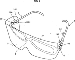
- the eyeglasses protection device 1 is equipped with a lens surface protective part 2 and a plurality of temple protective parts 3.
- the lens surface protective part 2 protects a lens surface 4a of eyeglasses 4.
- the temple protective parts 3 are formed at both ends of the lens surface protective part 2 in a length direction and protect temples 5 of the eyeglasses 4.
- the temple protective parts 3 have attachment parts 3A and 3B. By the attachment parts 3A and 3B, the eyeglasses protection device 1 is attached to the eyeglasses 4 or is detached from the eyeglasses 4.
- the eyeglasses protection device 1 protects a user of the eyeglasses protection device 1 (hereinafter, also simply referred to as a "user") from various airborne substances (liquid such as blood or body fluid or various aggregated substances, for example) by protecting the lens surface 4a and the temples 5 of the eyeglasses 4.
- various airborne substances liquid such as blood or body fluid or various aggregated substances, for example
- the type of the eyeglasses 4 to which the eyeglasses protection device 1 is attached is not particularly limited.
- the eyeglasses 4 include various correctional eyeglasses, magnifying lenses for surgery (provided with the temples 5), and 3D image eyeglasses.
- the 3D image eyeglasses may be used for viewing 3D images displayed by various display devices.
- a 3D image is formed of a right eye image and a left eye image.
- the right eye image and the left eye image differ from each other.
- minimally invasive scopic surgeries are performed more often in recent years.
- As an endoscopic device for performing endoscopic surgery a 3D endoscopic device capable of performing stereoscopic observation of a target of treatment has been employed.
- the 3D endoscopic device displays a 3D image of the target of treatment.
- a 3D scheme applied to the 3D endoscopic device a circular polarization scheme is exemplified.
- the eyeglasses protection device 1 according to the embodiment can also be applied to eyeglasses used for such a 3D endoscopic device.
- the lens surface protective part 2 is a member that protects the lens surface 4a of the eyeglasses 4 as described above. That is, the lens surface protective part 2 is arranged outside the lens surface 4a when the eyeglasses protection device 1 is attached to the eyeglasses 4.
- the lens surface protective part 2 is preferably wider than the lens surface 4a.
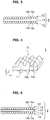
- the lens surface protective part 2 is equipped with a substrate film 11 and a micro concavo-convex structure 12 as illustrated in FIG. 3 .
- the substrate film 11 is formed of a material that has at least transparency.
- the material forming the substrate film is not particularly limited as long as the material has transparency.
- a refractive index of the substrate film 11 is preferably from 1.30 to 2.00, and is preferably from 1.34 to 2.00, for example.
- the material forming the substrate film preferably has flexibility as well as transparency.
- a plastic material is exemplified.
- plastic material examples include methyl methacrylate (co)polymer, polycarbonate, triacetyl cellulose, polyethylene, polyethylene terephthalate, polyethylene naphthalate, polystyrene, styrene (co)polymer, methyl methacrylate-styrene copolymer, polymethyl methacrylate, cellulose diacetate, cellulose triacetate, cellulose acetate butyrate, polyvinyl alcohol, polyester, polyamide, polyimide, polyether sulfone, cycloolefin, polysulfone, polypropylene, polymethylpentene, polyvinyl chloride, polyvinyl acetal, polyether ketone, polyurethane, and glass, the plastic material is not limited thereto.
- the substrate film 11 is formed of the above plastic material
- the substrate film 11 is manufactured by a method of stretching the above plastic material or forming a film after diluting the plastic material in a solvent and drying the material.
- various underlayers may be formed on the surface of the substrate film 11.
- various underlayers may be formed on the surface of the substrate film 11.
- a material forming the underlayer is not particularly limited as long as the material can achieve the above object.
- the material forming the underlayer include an organo alkoxy metal compound, polyester, acrylic-modified polyester, and polyurethane. Corona discharge processing, UV irradiation processing, or the like may be performed on the surface of the substrate film 11 instead of forming the underlayer.
- the eyeglasses protection device 1 When the eyeglasses 4 are used to view a 3D image based on a circular polarization scheme, the eyeglasses protection device 1 is required to suppress disturbance of polarization. Disturbance of the polarization of the 3D image due to the eyeglasses protection device 1 may cause problems such as crosstalk.
- the crosstalk means that the right eye image is seen by the left eye and the left eye image is seen by the right eye. In order to improve visibility of the 3D image, it is preferable that crosstalk occur as little as possible.
- a crosstalk value is known as a scale of crosstalk, and a range of the crosstalk value allowable for the 3D image is from 5% to 10% in some cases.
- a method of setting an in-plane retardation value of the eyeglasses protection device 1 to be equal to or less than 100 nm with respect to a wavelength of visible light is exemplified.
- a method of setting the in-plane retardation value of the eyeglasses protection device 1 to a value within the above range a method of forming the substrate film 11 of a non-stretched film is exemplified. Since the non-stretched film has a lower molecular orientation property than a stretched film and has small deviation in orientation, it is possible to set a small in-plane retardation value and thereby to set a small crosstalk value.
- the substrate film 11 is preferably formed of the non-stretched film.
- the in-plane retardation value of the eyeglasses protection device 1 it is possible to set the in-plane retardation value of the eyeglasses protection device 1 to be equal to or less than 100 nm with respect to the wavelength of visible light.
- the material forming the non-stretched film include polycarbonate, polyethylene terephthalate, triacetyl cellulose, polyester, polyethylene naphthalate, polystyrene, polyurethane, polyvinyl alcohol, polymethyl methacrylate, cycloolefin, polypropylene, and polyethylene from among the materials exemplified above. Polycarbonate is preferably used in view of shock resistance and versatility.
- the in-plane retardation value of the eyeglasses protection device 1 is preferably equal to or less than 100 nm, is more preferably equal to or less than 30 nm, and is more preferably equal to or less than 20 nm. By setting the in-plane retardation value of the eyeglasses protection device 1 to a value within these ranges, it is possible to further suppress crosstalk.
- the in-plane retardation value of the eyeglasses protection device 1 can be adjusted by selecting the material of the non-stretching film exemplified above and the thickness of the substrate film 11, for example. Also, the retardation value can be measured by various phase difference measurement devices.
- the thickness of the substrate film 11 is not particularly limited and may be appropriately selected in accordance with a purpose of use of the eyeglasses protection device 1.
- the thickness of the substrate film 11 may be from about 10 ⁇ m to about 500 ⁇ m, for example.
- the "film” in the embodiment includes a "sheet,” a “plate,” and the like.
- the micro concavo-convex structure 12 includes a plurality of convex parts 12a that protrude in a film thickness direction of the substrate film 11 and a plurality of concave portions 12b that are recessed in the film thickness direction of the substrate film 11.
- the convex parts 12a and the concave parts 12b are periodically arranged on the substrate film 11.
- the convex parts 12a and the concave parts 12b are arranged in a houndstooth pattern. It is a matter of course that the convex parts 12a and the concave parts 12b may be arranged in another arrangement pattern.
- the convex parts 12a and the concave parts 12b may be arranged in a rectangular check pattern. Alternatively, the convex parts 12a and the concave parts 12b may be randomly arranged. Shapes of the convex parts 12a and the concave parts 12b are not particularly limited. The shapes of the convex parts 12a and the concave parts 12b may be a conical shape, a columnar shape, or a needle shape, for example. The shape of the concave parts 12b is a shape formed by inner wall surfaces of the concave parts 12b.
- An average period of the concavo-convex parts of the micro concavo-convex structure 12 is equal to or less than the wavelength of visible light (for example, equal to or less than 830 nm), is preferably equal to or greater than 100 nm and equal to or less than 350 nm, and is further preferably equal to or greater than 150 nm and equal to or less than 280 nm. Therefore, the micro concavo-convex structure 12 is a so-called moth-eye structure.
- an average period of less than 100 nm is not preferable because there is a possibility of the micro concavo-convex structure 12 becoming difficult to form.
- an average period of greater than 350 nm is not preferable because there is a possibility of a diffraction phenomenon of visible light occurring.
- the average period of the micro concavo-convex structure 12 is an arithmetic mean value of distances between mutually adjacent convex parts 12a and concave parts 12b.
- the micro concavo-convex structure 12 can be observed with a scanning electron microscope (SEM) or a cross-sectional transmission electron microscope (cross-sectional TEM), for example.
- a method of calculating the average period is as follows, for example. That is, a plurality of combinations of adjacent concave parts 12b and a plurality of combinations of adjacent convex parts 12a are picked up, and distances thereof are measured. The average period may be calculated by obtaining an arithmetic mean of the measured values.
- the micro concavo-convex structure 12 is formed on both surfaces of the substrate film 11 in FIGS. 3 and 4 , the micro concavo-convex structure 12 may be formed on at least one surface.
- the micro concavo-convex structure 12 is formed of a hardened curable resin.
- the hardened curable resin is required to have at least transparency.
- the refractive index of the hardened curable resin is preferably similar to that of the substrate film 11. It is possible to suppress internal reflection of the lens surface protective part 2 in such a case and to thereby improve contrast of an image viewed through the eyeglasses protection device 1.
- the curable resin contains a polymerizable compound and a curing initiator.
- the polymerizable compound is a resin polymerized and cured by the curing initiator.
- examples of the polymerizable compound include an epoxy polymerizable compound and an acrylic polymerizable compound.
- the epoxy polymerizable compound is a monomer, oligomer, or prepolymer containing one epoxy group or two or more epoxy groups in a molecule.
- Examples of the epoxy polymerizable compound include various kinds of bisphenol-type epoxy resins (bisphenol A type, F type, and the like), novolac-type epoxy resins, various kinds of modified epoxy resins such as rubber and urethane, a naphthalene-type epoxy resin, a biphenyl-type epoxy resin, a phenol novolac-type epoxy resin, a stilbene-type epoxy resin, a triphenolmethane-type epoxy resin, a dicyclopentadiene-type epoxy resin, a triphenylmethane-type epoxy resin, and a prepolymer thereof.
- bisphenol-type epoxy resins bisphenol A type, F type, and the like
- novolac-type epoxy resins various kinds of modified epoxy resins such as rubber and urethane
- a naphthalene-type epoxy resin such as a biphenyl-type epoxy resin
- a phenol novolac-type epoxy resin such as stilbene-type epoxy resin
- the acrylic polymerizable compound is a monomer, an oligomer, or a prepolymer containing one acryl group or two or more acryl groups in a molecule.
- monomers are further classified into monofunctional monomers containing one acryl group in the molecule, bifunctional monomers containing two acryl groups in the molecule, and polyfunctional monomers containing three or more acryl groups in the molecule.
- “monofunctional monomer” examples include carboxylic acids (acrylic acid), hydroxy compounds (2-hydroxyethyl acrylate, 2-hydroxypropyl acrylate, and 4-hydroxybutyl acrylate), alkyl or alicyclic monomers (isobutyl acrylate, t-butyl acrylate, isooctyl acrylate, lauryl acrylate, stearyl acrylate, isobornyl acrylate, and cyclohexyl acrylate), other functional monomers (2-methoxyethyl acrylate, methoxyethylene glycol acrylate, 2-ethoxyethyl acrylate, tetrahydrofurfuryl acrylate, benzyl acrylate, ethyl carbitol acrylate, phenoxyethyl acrylate, N,N-dimethylaminoethyl acrylate, N,N-dimethylaminopropylacrylamide, N,N-dimethyl
- bifunctional monomers include tri(propylene glycol) diacrylate, trimethylolpropane-diallyl ether, and urethane acrylate.
- polyfunctional monomers examples include trimethylolpropane triacrylate, dipentaerythritol penta-/hexa-acrylate, and ditrimethylolpropane tetraacrylate.
- acrylic polymerizable compounds described above examples include acryl morpholine, glycerol acrylate, polyether-based acrylate, N-vinylformamide, N-vinylcaprolactone, ethoxy diethyleneglycol acrylate, methoxy triethyleneglycol acrylate, polyethyleneglycol acrylate, EO-modified trimethylolpropane triacrylate, EO-modified bisphenol A diacrylate, aliphatic urethane oligomer, and polyester oligomer.
- acrylic polymerizable compounds described above 2-hydroxyethyl acrylate, acryl morpholine, glycerol acrylate, polyether-based acrylate, N-vinylformamide, N-vinylpyrrolidone, N-vinylcaprolactone, ethoxy diethyleneglycolacrylate, methoxy triethyleneglycolacrylate, polyethyleneglycolacrylate, EO-modified trimethylolpropane triacrylate, EO-modified bisphenol A diacrylate, aliphatic urethane oligomer, polyester oligomer, and the like are preferably used.
- the curing initiator is a material for curing the curable resin.
- the curing initiator include a thermosetting initiator and a photocuring initiator.
- the curing initiator may cure the curable resin using an energy beam (an electron beam, for example) other than heat and light.
- an energy beam an electron beam, for example
- the curable resin is a thermosetting resin.
- the curing initiator is a photocuring initiator
- the curable resin is a photocurable resin.
- the curing initiator is preferably an ultraviolet curing initiator. Therefore, the curable resin is preferably an ultraviolet curable resin.
- the ultraviolet curing initiator is a kind of photocuring initiator. Examples of the ultraviolet curing initiator include 2,2-dimethoxy-1,2-diphenylethane-1-one, 1-hydroxy-cyclohexylphenylketone, and 2-hydroxy-2-methyl-1-phenylpropane-1-one.
- additive agents may be added to the curable resin in accordance with a purpose of use of the eyeglasses protection device 1.
- additive agents include an inorganic filler, an organic filler, a leveling agent, a surface conditioner, and an antifoam agent.
- an inorganic filler it is possible to exemplify metal oxide fine particles such as SiO 2 , TiO 2 , ZrO 2 , SnO 2 , and Al 2 O 3 .
- the micro concavo-convex structure 12 may be given various properties (hydrophilicity or water repellency, for example) in accordance with a purpose of use of the eyeglasses protection device 1. For example, giving the micro concavo-convex structure 12 hydrophilicity or water repellency in accordance with a purpose of use of the eyeglasses protection device 1 can make the eyeglasses protection device 1 less likely to mist over.
- the micro concavo-convex structure 12 preferably has hydrophilicity.
- the micro concavo-convex structure 12 is formed on both surfaces of the substrate film 11.
- Materials and properties of the micro concavo-convex structure 12 may be the same as or different from each other. That is, the materials and the properties of the micro concavo-convex structure 12 may be determined in accordance with a purpose of use of the eyeglasses protection device 1.
- the lens surface protective part 2 is equipped with the micro concavo-convex structure 12 as described above, it is possible to give the lens surface protective part 2 an excellent reflection preventing function. Specifically, the refractive index on a light advancing direction successively varies when light enters the surface of the lens surface protective part 2. When the refractive index steeply varies at any part in the light advancing direction, the part becomes an optical interface. Then, the light is reflected at that part. Since the micro concavo-convex structure 12 is formed on the surface of the lens surface protective part 2 in the embodiment, the refractive index successively varies at that part. That is, the surface of the lens surface protective part 2 is less likely to become the optical interface.
- the lens surface protective part 2 is less likely to reflect light.
- the refractive index on the light advancing direction successively varies regardless of an incident angle of the light entering the lens surface protective part 2. Therefore, the micro concavo-convex structure 12 can set normal reflectance of the lens surface protective part 2 to be equal to or less than 5%, preferably equal to or less than 1%, and further preferably 0.5% regardless of a reflection angle.
- the value of the normal reflectance can be adjusted by adjusting the average period or the like of the micro concavo-convex structure 12.
- the normal reflectance can be greatly reduced by forming the micro concavo-convex structure 12 on both surfaces of the substrate film 11.
- the eyeglasses protection device 1 can preferably be used as an eyeglasses protection device for medical use.
- the micro concavo-convex structure 12 may be integrally formed with the substrate film 11.
- the substrate film 11 is formed of a material that forms the micro concavo-convex structure 12, namely the curable resin.
- a base layer 13 may be formed between the substrate film 11 and the micro concavo-convex structure 12.
- the base layer 13 is formed of the same material as the micro concavo-convex structure 12, for example.
- the temple protective parts 3 are provided at both ends of the lens surface protective part 2 in the length direction and protect the temples 5 of the eyeglasses 4. That is, the temple protective parts 3 are arranged outside the temples 5 when the eyeglasses protection device 1 is attached to the eyeglasses 4.
- the length of the temple protective parts 3 in the vertical direction is preferably longer than the length of the temples 5 in the vertical direction.
- the eyeglasses protection device 1 is manufactured by cutting a reflection protective film 110 equipped with the substrate film 11 and the micro concavo-convex structure 12 into the shape of the eyeglasses protection device 1 as will be described later in detail.
- the temple protective parts 3 also include the substrate film 11 and the micro concavo-convex structure 12.
- the temple protective parts 3 may be formed of a film different from that of the lens surface protective part 2.
- the eyeglasses protection device 1 may be manufactured by separately manufacturing the temple protective parts 3 and the lens surface protective part 2 and bonding the parts.
- the temple protective parts 3 are divided into a left temple protective part 31 for protecting the temple 5 on the left side and a right temple protective part 32 for protecting the temple 5 on the right side.
- the left temple protective part 31 includes an attachment part 3A
- the right temple protective part 32 includes an attachment part 3B. Both of the attachment parts 3A and 3B are for attaching the eyeglasses protection device 1 to the eyeglasses 4 or detaching the eyeglasses protection device 1 from the eyeglasses 4.
- the attachment part 3A includes insertion holes 15 and 16, auxiliary cut holes 17, and auxiliary holding parts 18.
- the insertion holes 15 and 16 are holes into which the temple 5 is inserted.
- the insertion holes 15 and 16 extend in a direction substantially perpendicular to an insertion direction of the temple 5.
- the length of the insertion holes 15 and 16 in the vertical direction is equal to or greater than the length (height) of the temple 5 in the vertical direction.
- the insertion holes 15 and 16 extend substantially parallel to each other and are aligned in the insertion direction of the temple 5.
- the insertion holes 15 and 16 are manufactured by forming cut holes at the left temple protective part 31. Additional insertion holes with the same function as the insertion holes 15 and 16 may be formed. That is, the number of the insertion holes may be three or more.
- the auxiliary cut holes 17 are cut holes extending from outer edges of the insertion holes 15 and 16 toward the outside. Although a plurality of auxiliary cut holes are preferably formed for each of the insertion holes 15 and 16, it is only necessary that one or more auxiliary cut holes be formed for each of the insertion holes 15 and 16. When the temple 5 can be sufficiently held only by the insertion holes 15 and 16, the auxiliary cut holes 17 may be omitted. Although the auxiliary cut holes 17 preferably extend in a perpendicular direction from the insertion holes 15 and 16 as illustrated in FIG. 1 , the auxiliary cut holes 17 may extend in an oblique direction from the insertion holes 15 and 16.
- the auxiliary holding parts 18 are parts formed in the circumferences of the insertion holes 15 and 16 by the auxiliary cut holes 17 and hold the temple 5 when the temple 5 is inserted into the insertion holes 15 and 16.
- the attachment part 3A holds the temple 5 as follows. That is, the user arranges the eyeglasses 4 on the rear surface side of the eyeglasses protection device 1 and inserts the temple 5 into the insertion holes 15 and 16 in order.
- the insertion holes 15 and 16 hold the temple 5.
- the temple 5 is pinched between a portion arranged between the insertion holes 15 and 16 and portions arranged outside the insertion holes 15 and 16 from among the portions forming the left temple protective part 31. That is, these portions pinch the temple 5 by elastic restoring force.
- the auxiliary holding parts 18 also hold the temple 5.
- the attachment part 3A holds the temple 5 with the insertion holes 15 and 16, the portion arranged between the insertion holes 15 and 16, the portions arranged outside the insertion holes 15 and 16, and the auxiliary holding parts 18. Since the temple 5 can be further firmly held by the auxiliary holding parts 18, it is possible to suppress positional deviation of the temple 5, rattling, and the like even when the length of the insertion holes 15 and 16 in the vertical direction is greater than the length of the temple 5 in the vertical direction. Also, the user can move the temple 5 in the insertion direction. In this way, the user can adjust the attachment position of the eyeglasses protection device 1.
- the attachment part 3B includes insertion holes 21 and 22, a traverse cut hole 23, an upper holding part 20A, a lower holding part 20B, auxiliary cut holes 24, and auxiliary holding parts 25.
- the insertion holes 21 and 22, the auxiliary cut holes 24, and the auxiliary holding parts 25 are the same as the insertion holes 15 and 16, the auxiliary cut holes 17, and the auxiliary holding parts 18.
- the traverse cut hole 23 is a cut hole crossing between the adjacent insertion holes 21 and 22 in an oblique direction.
- the upper holding part 20A and the lower holding part 20B are parts formed by the insertion holes 21 and 22 and the traverse cut hole 23. That is, the portion arranged between the insertion holes 21 and 22 from among the portions forming the right temple protective part 32 is divided into the upper holding part 20A and the lower holding part 20B by the traverse cut hole 23.
- the attachment part 3B holds the temple 5 as follows. The user fixes the left temple protective part 31 to the temple 5. Then, the user causes the attachment part 3A to approach the side of the lens surface 4a of the eyeglasses 4. Then, the user covers the lens surface 4a with the lens surface protective part 2 and arranges the right temple protective part 32 outside the temple 5. Then, the user arranges the upper holding part 20A and the lower holding part 20B inside the temple 5 by pressing the upper holding part 20A and the lower holding part 20B thereinto from the outside.
- the insertion holes 21 and 22 hold the temple 5. Furthermore, the temple 5 is pinched by the upper holding part 20A, the lower holding part 20B, and portions arranged outside the insertion holes 21 and 22. That is, these portions pinch the temple 5 by elastic restoring force. Furthermore, the auxiliary holding parts 25 also hold the temple 5.
- the attachment part 3B holds the temple 5 with the insertion holes 21 and 22, the upper holding part 20A, the lower holding part 20B, the portions arranged outside the insertion holes 21 and 22, and the auxiliary holding parts 25. Since the auxiliary holding parts 25 can further firmly hold the temple 5, it is possible to suppress positional deviation of the temple 5, rattling, and the like even when the length of the insertion holes 21 and 22 in the vertical direction is greater than the length of the temple 5 in the vertical direction. Also, the user can move the temple 5 in the insertion direction. In this way, the user can adjust the attachment position of the eyeglasses protection device 1.
- the traverse cut hole 23 is formed between the upper holding part 20A and the lower holding part 20B. Therefore, it is only necessary for the user to detach the temple 5 from the right temple protective part 32 while pressing the upper holding part 20A and the lower holding part 20B in the vertical direction for detaching the right temple protective part 32 from the temple 5. As described above, the user can easily detach the right temple protective part 32 from the temple 5.
- the attachment part 3A is formed at the left temple protective part 31, and the attachment part 3B is formed at the right temple protective part 32.
- the traverse cut hole 23 is formed only at the attachment part 3B. Therefore, the eyeglasses protection device 1 is configured such that the temple 5 can be easily detached from the attachment part 3B while the temple protective parts 3 are firmly held at the temples 5 by the attachment parts 3A and 3B. Therefore, it is possible to firmly hold the temple 5 with the attachment part 3A even if the temple 5 falls from the attachment part 3B. That is, the eyeglasses protection device 1 is less likely to fall from the eyeglasses 4.
- the installation positions of the attachment parts 3A and 3B may be opposite in the horizontal direction.
- the attachment part 3A may be formed at both the left temple protective part 31 and the right temple protective part 32, or the attachment part 3B may be formed at both the left temple protective part 31 and the right temple protective part 32.
- the attachment part 3A is preferably formed at one of the temple protective parts 3 while the attachment part 3B is formed at the other in order to achieve both firm holding and easy detachment.
- the attachment part 3B and the temple 5 may be attached to each other with an adhesive tape, for example.
- the attachment parts 3A and 3B may be omitted, and in such a case, the temple protective parts 3 may be fixed to the temples 5 with an adhesive tape or the like.
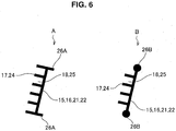
- breakage suppression holes 26A and 26B maybe formed at upper and lower ends of the insertion holes 15, 16, 21, and 22.
- the breakage suppression hole 26A is a cut hole extending in a direction perpendicular to a length direction of the insertion holes 15, 16, 21, and 22. It is only necessary for the breakage suppression hole 26A to extend in a direction intersecting the length direction of the insertion holes 15, 16, 21, and 22.
- the breakage suppression hole 26B is a hole with a diameter that is greater than the width of the insertion holes 15, 16, 21, and 22.
- breakage suppression holes 26A and 26B are formed at the upper and lower ends of the insertion holes 15, 16, 21, and 22, it is possible to suppress breakage of the temple protective parts 3 when a large burden is imparted on the upper and lower ends of the insertion holes 15, 16, 21, and 22 when the temples 5 are attached or detached, for example.
- first cut grooves 30A may be formed at boundary lines 30 between the lens surface protective part 2 and the temple protective parts 3.
- the first cut grooves 30A are formed on the surface (the surface on the side opposite to the surface that faces the user) of the eyeglasses protection device 1.
- the first cut grooves 30A do not penetrate the eyeglasses protection device 1. That is, the depth of the first cut grooves 30A is smaller than the thickness of the eyeglasses protection device 1. For example, the depth of the first cut grooves 30A is about a half of the thickness of the eyeglasses protection device 1.
- the first cut grooves 30A By forming the first cut grooves 30A at the boundary lines 30 between the lens surface protective part 2 and the temple protective parts 3, it becomes easier to deform the eyeglasses protection device 1 along the shape of the eyeglasses 4.
- the first cut groove 30A is not between the right temple protective part 32 and the lens surface protective part 2, for example, there is a possibility of the right temple protective part 32 falling off of the temple 5 due to elastic restoring force thereof.
- forming the first cut groove 30A between the right temple protective part 32 and the lens surface protective part 2 makes it possible to cause the right temple protective part 32 to be less likely to fall off of the temple 5.
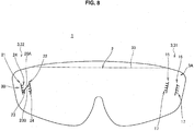
- a second cut groove 33 may be formed to cross the lens surface protective part 2 on the side of the upper end thereof.
- the second cut groove 33 is formed on the surface (the surface on the side opposite to the surface that faces the user) of the eyeglasses protection device 1.
- the second cut groove 33 does not penetrate the eyeglasses protection device 1. That is, the depth of the cut groove 33 is smaller than the thickness of the eyeglasses protection device 1. For example, the depth of the cut groove 33 is about a half of the thickness of the eyeglasses protection device 1.
- the user attaches the eyeglasses protection device 1 to the eyeglasses 4 using the following method.
- the user arranges the eyeglasses 4 on the rear surface side of the eyeglasses protection device 1 and inserts the temple 5 into the insertion holes 15 and 16 in order.
- the user causes the left temple protective part 31 to be held by the temple 5.
- the user causes the attachment part 3A to approach the side of the lens surface 4a of the eyeglasses 4.
- the user covers the lens surface 4a with the lens surface protective part 2 and arranges the right temple protective part 32 outside the temple 5.
- the user arranges the upper holding part 20A and the lower holding part 20B inside by pressing the upper holding part 20A and the lower holding part 20B thereinto from the outside. In this way, the user causes the right temple protective part 32 to be held by the temple 5.
- the user attaches the eyeglasses protection device 1 to the eyeglasses 4 through the above processes. Thereafter, the user wears the eyeglasses 4 to which the eyeglasses protection device 1 has been attached and performs various operations.
- the eyeglasses protection device 1 can protect the user from various airborne substances by being attached to the eyeglasses. Furthermore, the lens surface protective part 2 is formed of a material with transparency, and the in-plane retardation value is equal to or less than 100 nm with respect to the wavelength of visible light. Therefore, the eyeglasses protection device 1 can maintain visibility and operability for the user even when the user views a 3D image.
- the micro concavo-convex structure 12 is formed on the surface of the lens surface protective part 2, it is possible to suppress occurrence of reflected light that may enter the eyes of the user of the eyeglasses protection device 1. Therefore, it is possible to suppress glare and eyestrain of the user due to the reflected light. Also, the micro concavo-convex structure 12 can suppress occurrence of reflected light in a wider wavelength band than a reflection protective film that is used in a liquid crystal display or the like and responds to a specific wavelength. Therefore, the user can view an operation target with substantially the same color both in a case in which the user views the operation target through the lens surface protective part 2 and in a case in which the user views the operation target without the lens surface protective part 2. Also, the user who wears the eyeglasses protection device 1 can easily cope with variations in illuminance even if circumferential illuminance greatly varies.
- the eyeglasses protection device 1 can be used not only for medical use but for various purposes of use.
- an eyeglasses protection device laminated article 50 may be formed by laminating a plurality of eyeglasses protection devices 1.
- the plurality of eyeglasses protection devices 1 are bonded to each other by adhesive layers 51.
- the eyeglasses protection devices 1 can be attached and detached.
- the adhesive layers 51 may be formed only at a part of the interfaces between the plurality of eyeglasses protection devices 1. In such a case, a part of the interfaces forms a space 52.
- the adhesive layers 51 are preferably formed at positions at which the adhesive layers 51 do not obstruct a field of view of the user, such as at an outer circumferential portion of the lens surface protective part 2 or at temple protective parts 3.
- the adhesive layers 51 may be formed to have a predetermined length in the vertical direction of the temple protective parts 3, for example. Alternatively, the adhesive layers 51 may be formed at a predetermined interval in the vertical direction of the temple protective parts 3.
- the adhesive layers 51 are formed only at a part of the interfaces between the plurality of eyeglasses protection devices 1, a peeling property of the eyeglasses protection devices 1 is enhanced. Also, since the adhesive layers 51 are not likely to remain on the eyeglasses protection device laminated article 50, it is possible to suppress degradation of visibility due to remaining substances (residues) of the adhesive layers 51. In addition, it is possible to suppress variations in the thickness of the eyeglasses protection device laminated article 50 due to the adhesive layers 51.
- the plurality of eyeglasses protection devices 1 may or may not be in contact with each other at these interfaces. Tip ends of the convex parts 12a of the micro concavo-convex structure 12 may or may not be in contact with each other. Alternatively, the convex parts 12a of one eyeglasses protection device 1 may enter the concave parts 12b of another eyeglasses protection device 1. When the convex parts 12a and the concave parts 12b of the micro concavo-convex structure 12 are regularly aligned, satisfactory adhesiveness is obtained at the interfaces between the plurality of eyeglasses protection devices 1.
- the following effects can be expected as well as the aforementioned effects when the plurality of eyeglasses protection devices 1 are laminated.
- the user can peel the frontmost eyeglasses protection device 1 from the eyeglasses protection device laminated article 50 when the eyeglasses protection device 1 is contaminated by airborne substances. In such a case, the user can immediately recover the field of view when the airborne substances obstruct the field of view. Also, it is not necessary for the user to remove (wipe, for example) the airborne substances from the eyeglasses protection device laminated article 50 even when the airborne substances obstruct the field of view. Further, when the airborne substances have an adverse effect on the human body, the user should not touch the airborne substances. In such a case, the user can recover the field of view without touching the airborne substances.
- the space 52 at the interfaces formed between the plurality of eyeglasses protection devices 1, if there is any, does not substantially damage transparency.
- the micro concavo-convex structure 12 can suppress occurrence of reflected light at the interfaces between the plurality of eyeglasses protection devices 1.
- the adhesive layers 51 may be formed on the entire interfaces between the plurality of eyeglasses protection devices 1. In such a case, a composition of the adhesive layers 51 is selected such that the refractive index of the adhesive layers 51 is a value that does not disturb visibility.
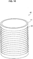
- the micro concavo-convex structure 12 is manufactured using an original board 40 illustrated in FIG. 10 .
- a configuration of the original board 40 will be described below.
- the original board 40 is an original board used in a nanoimprint method, for example, and has a cylindrical shape.
- the original board 40 may have a columnar shape or another shape (a plate shape, for example).
- a micro concavo-convex structure 42 of the original board 40 can be transferred to a resin base material or the like in a seamless manner by a roll-to-roll scheme. In this way, it is possible to manufacture the reflection protective film 110 (see FIG.
- the reflection protective film 110 is a film equipped with the substrate film 11 and the micro concavo-convex structure 12, and the eyeglasses protection device 1 is manufactured by cutting the reflection protective film 110 into the shape of the eyeglasses protection device 1.
- the shape of the original board 40 is preferably a cylindrical shape or a columnar shape.
- the original board 40 is equipped with an original board base material 41 and the micro concavo-convex structure 42 formed on the surface of the original board base material 41.
- the original board base material 41 is a glass body, for example, and specifically, is made of silica glass.
- the original board base material 41 is not particularly limited as long as SiO 2 purity is high, and the original board base material 41 may be formed of fused silica glass, synthesized silica glass, or the like.
- the shape of the original board base material 41 is a cylindrical shape, a columnar shape or another shape is also applicable.
- the original board base material 41 preferably has a cylindrical shape or a columnar shape as described above.
- the micro concavo-convex structure 42 has an inverted shape compared to the micro concavo-convex structure 12.
- a base material resist layer is formed (film formation) on the original board base material 41.
- a resist material forming the base material resist layer is not particularly limited, and any of an organic resist material and an inorganic resist material may be used.
- the organic resist material include a novolac-based resist or a chemically amplified resist.
- the inorganic resist material include a metal oxide containing one kind or two or more kinds of transition metals such as tungsten (W) or molybdenum (Mo).
- the base material resist layer is preferably formed of a thermal-reaction-type resist containing a metal oxide in order to perform thermal reaction lithography.
- the base material resist layer may be formed on the original board base material 41 using spin coating, slit coating, dip coating, spray coating, screen printing, or the like.
- the base material resist layer may be formed using a sputtering method.
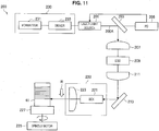
- a latent image is formed on the base material resist layer by exposing a part of the base material resist layer with an exposure device 200 (see FIG. 11 ).
- the exposure device 200 modulates laser light 200A and irradiates the base material resist layer with the laser light 200A.
- the latent image corresponding to the micro concavo-convex structure 42 can be formed on the base material resist layer.
- the latent image is formed on the base material resist layer in an average period of equal to or less than the wavelength of visible light.
- the base material resist layer is developed by dropping a developer onto the base material resist layer on which the latent image has been formed.
- the micro concavo-convex structure is formed on the base material resist layer.
- the micro concavo-convex structure 42 is formed on the original board base material 41 by etching the original board base material 41 and the base material resist layer by using the base material resist layer as a mask.
- an etching method is not particularly limited, dry etching with perpendicular anisotropy is preferably performed, and for example, Reactive Ion Etching (RIE) is preferably performed.
- RIE Reactive Ion Etching
- the exposure device 200 is a device for exposing the base material resist layer.
- the exposure device 200 is equipped with a laser light source 201, a first mirror 203, a photodiode (PD) 205, a polarization optical system, a control mechanism 230, a second mirror 213, a moving optical table 220, a spindle motor 225, and a turn table 227.
- the original board base material 41 is placed on the turn table 227 and can rotate.
- the laser light source 201 is a light source that emits the laser light 200A and is a solid laser or a semiconductor laser, for example.
- a wavelength of the laser light 200A emitted by the laser light source 201 is not particularly limited, the wavelength may be in a blue light band from 400 nm to 500 nm, for example.
- the laser light 200A may have any spot diameter (the diameter of a spot with which the resist layer is irradiated) as long as the spot diameter is smaller than the diameter of the opening surfaces of the concave parts of the micro concavo-convex structure 42, and the spot diameter may be about 200 nm, for example.
- the laser light 200A emitted from the laser light source 201 is controlled by the control mechanism 230.
- the laser light 200A emitted from the laser light source 201 advances straight as a parallel beam, is reflected by the first mirror 203, and is guided into the polarization optical system.
- the first mirror 203 is formed of a polarization beam splitter and has a function of reflecting one polarization component and transmitting the other polarization component.
- the polarization component that has penetrated the first mirror 203 is received by the photodiode 205 and is subjected to photoelectric conversion.
- a received light signal obtained by the photoelectric conversion performed by the photodiode 205 is input to the laser light source 201, and the laser light source 201 performs phase modulation of the laser light 200A based on the input received light signal.
- the polarization optical system is equipped with a condenser lens 207, an Electro Optic Deflector (EOD) 209, and a collimator lens 211.
- EOD Electro Optic Deflector
- the laser light 200A is collected by the electro optic deflector 209 through the condenser lens 207.
- the electro optic deflector 209 is an element capable of controlling an irradiation position of the laser light 200A.
- the exposure device 200 can also change the irradiation position of the laser light 200A guided onto the moving optical table 220 by the electro optic deflector 209.
- the irradiation position of the laser light 200A is adjusted by the electro optic deflector 209, and the laser light 200A is then formed into a parallel beam again by the collimator lens 211.
- the laser light 200A emitted from the polarization optical system is reflected by the second mirror 213 and is guided onto the moving optical table 220 in a horizontal and parallel manner.
- the moving optical table 220 is equipped with a Beam expander (BEX) 221 and an objective lens 223.
- BEX Beam expander
- the laser light 200A guided to the moving optical table 220 is formed into a desired beam shape by the beam expander 221, and the base material resist layer formed on the original board base material 41 is then irradiated with the laser light 200A via the objective lens 223.
- the moving optical table 220 moves in a direction of the arrow R (a feed pitch direction) by a single feed pitch (track pitch) every time the original board base material 41 rotates once.
- the original board base material 41 is installed on the turn table 227.
- the spindle motor 225 rotates the original board base material 41 by rotating the turn table 227.
- the control mechanism 230 is equipped with a formatter 231 and a driver 233 and controls irradiation with the laser light 200A.
- the formatter 231 generates a modulation signal for controlling irradiation with the laser light 200A
- the driver 233 controls the laser light source 201 based on the modulation signal generated by the formatter 231. In this way, the irradiation of the original board base material 41 with the laser light 200A is controlled.
- the formatter 231 generates a control signal for irradiating the base material resist layer with the laser light 200A based on an input image of an arbitrary pattern depicted on the base material resist layer. Specifically, the formatter 231 acquires an input image of an arbitrary pattern to be depicted on the base material resist layer first.
- the input image is an image corresponding to a developed diagram of an outer circumferential surface of the base material resist layer obtained by cutting the outer circumferential surface of the base material resist layer in an axial direction and expanding the outer circumferential surface in a plane.
- the formatter 231 divides the input image into small regions with a predetermined size (divides the input image in a lattice shape, for example) and determines whether or not the depicted image pattern is included in each of the small regions. Subsequently, the formatter 231 generates a control signal for performing control to irradiate the small regions that have been determined to include the depicted image pattern with the laser light 200A. Furthermore, the driver 233 controls an output of the laser light source 201 based on the control signal generated by the formatter 231. In this way, the irradiation of the base material resist layer with the laser light 200A is controlled.
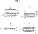
- an uncured resin layer 310 is formed by applying an uncured curable resin to the substrate film 11 as illustrated in FIG. 12(A) . Then, the micro concavo-convex structure 42 of the original board 40 is pressed onto the uncured resin layer 310. Then, the uncured resin layer 310 is cured by irradiating the uncured resin layer 310 with an energy beam from an energy beam source 309.
- a type of the energy beam emitted from the energy beam source 309 may be selected depending on the type of the curable resin.
- Examples of the type of the energy beam include an electron beam, an ultraviolet beam, an infrared beam, a laser light beam, a visible light beam, ionizing radiation (such as X rays, ⁇ rays, ⁇ rays, and ⁇ rays), microwaves, and radio-frequency radiation.
- ionizing radiation such as X rays, ⁇ rays, ⁇ rays, and ⁇ rays
- microwaves and radio-frequency radiation.
- the micro concavo-convex structure 42 is transferred to the uncured resin layer 310. That is, the micro concavo-convex structure 12 is formed on one surface of the substrate film 11 as illustrated in FIG. 12(B) . In this way, a reflection protective film 110 with the micro concavo-convex structure 12 formed on one surface is formed. When it is desired to form the micro concavo-convex structure 12 on both surfaces of the reflection protective film 110, the following process is further performed.
- the uncured resin layer 310 is formed by applying an uncured curable resin to the other surface (the surface on which the micro concavo-convex structure 12 is not formed) of the reflection protective film 110 illustrated in FIG. 12(B) . Thereafter, the micro concavo-convex structure 42 of the original board 40 is pressed onto the uncured resin layer 310 as illustrated in FIG. 12(C) . Then, the uncured resin layer 310 is cured by irradiating the uncured resin layer 310 with an energy beam from the energy beam source 309. In this way, the micro concavo-convex structure 42 is transferred to the uncured resin layer 310. That is, the micro concavo-convex structure 12 is formed on the other surface of the substrate film 11 as illustrated in FIG.
- the reflection protective film 110 with the micro concavo-convex structure 12 formed on both surfaces is formed.
- the base layer 13 may be formed between the micro concavo-convex structure 12 and the substrate film 11.
- various protective films may be formed on the surface of the reflection protective film 110.
- a transfer device 300 illustrated in FIG. 13 is a transfer device based on a roll-to-roll scheme using the original board 40.
- the reflection protective film 110 can be manufactured by such a transfer device 300.
- the transfer device 300 manufactures the reflection protective film 110 using a photocurable resin. It is a matter of course that the reflection protective film 110 can be manufactured using another kind of curable resin.
- the transfer device 300 is equipped with the original board 40, a base material supply roll 301, a winding roll 302, guide rolls 303 and 304, a nip roll 305, a peeling roll 306, an application device 307, and the energy beam source 309.
- the base material supply roll 301 is a roll around which a long substrate film 11 has been wound in a roll shape
- the winding roll 302 is a roll around which the reflection protective film 110 is to be wound.
- the guide rolls 303 and 304 are rolls that transport the substrate film 11.
- the nip roll 305 is a roll that brings the substrate film 11 on which the uncured resin layer 310 has been laminated, that is, a transfer film 100 in close contact with the original board 40.
- the peeling roll 306 is a roll that peels the substrate film 11 on which the micro concavo-convex structure 12 has been formed, that is, the reflection protective film 110 from the original board 40.
- the application device 307 is equipped with application means such as a coater, applies uncured photocurable resin to the substrate film 11, and forms the uncured resin layer 310.
- the application device 307 may be a gravure coater, a wire bar coater, a die coater, or the like.
- the energy beam source 309 is a light source that emits light with a wavelength with which the photocurable resin can be cured and may be an ultraviolet lamp, for example.
- the substrate film 11 is successively fed from the base material supply roll 301 via the guide roll 303 according to the transfer device 300.
- the base material supply roll 301 may be changed to a base material supply roll 301 in another lot in the course of the feeding.
- the application device 307 applies the uncured photocurable resin to the fed substrate film 11, and the uncured resin layer 310 is laminated on the substrate film 11. In this way, the transfer film 100 is manufactured.
- the transfer film 100 is brought into close contact with the original board 40 by the nip roll 305.
- the energy beam source 309 cures the uncured resin layer 310 by irradiating the uncured resin layer 310 in close contact with the original board 40 with light.
- the micro concavo-convex structure 42 formed on the outer circumferential surface of the original board 40 is transferred to the uncured resin layer 310. That is, the micro concavo-convex structure 12 is formed on the substrate film 11. Subsequently, the substrate film 11 with the micro concavo-convex structure 12 formed thereon, that is, the reflection protective film 110, is peeled from the original board 40 by the peeling roll 306. Then, the reflection protective film 110 is wound by the winding roll 302 via the guide roll 304.
- the transfer device 300 transfers the shape of the outer circumference of the original board 40 to the transfer film 100 while transporting the transfer film 100 in a roll-to-roll manner. In this way, the reflection protective film 110 is manufactured.
- the substrate film 11 is formed as a thermoplastic resin film, and a heating device is arranged upstream from the original board 40. The heating device heats and softens the substrate film 11, and the substrate film 11 is then pressed onto the original board 40. In this way, the micro concavo-convex structure 42 formed on the circumferential surface of the original board 40 is transferred to the substrate film 11.
- the substrate film 11 may be a film formed of a resin other than the thermoplastic resin, and the substrate film 11 and the thermoplastic film may be laminated. In such a case, the laminated film is heated by the heating device and is then pressed onto the original board 40.
- the transfer device 300 can successively manufacture a transferred article to which the micro concavo-convex structure 42 formed on the original board 40 has been transferred, that is, the reflection protective film 110.
- the micro concavo-convex structure 42 formed on the circumferential surface of the original board 40 has a desired average period. Therefore, the micro concavo-convex structure 12 formed on the reflection protective film 110 has a desired average period.
- the shape of the eyeglasses protection device 1 is obtained from the reflection protective film 110 by cutting the reflection protective film 110 into the shape of the eyeglasses protection device 1. Then, the eyeglasses protection device 1 is manufactured by forming the attachment parts 3A and 3B in the cut reflection protective film 110.
- the cutting of the reflection protective film 110 and the formation of the attachment parts 3A and 3B may be performed using a numerically controlled cutting work machine, a laser work machine, a punching press machine, or the like.
- the punching press machine the cutting of the reflection protective film 110 and the formation of the attachment parts 3A and 3B can be performed in a single process. Therefore, the punching press machine is preferably used to manufacture the eyeglasses protection device 1.
- a plurality of types of eyeglasses protection devices were manufactured by changing the types of the substrate film 11 and the number of surfaces (one surface or both surfaces) on which the micro concavo-convex structure 12 was formed. Then, retardation values of these eyeglasses protection devices with respect to the wavelength of 550 nm, normal reflectance (%), and 3D performance were evaluated.
- the retardation values with respect to the measurement wavelength ( ⁇ ) of 550 nm were measured using a phase difference measurement device (RETS-100: Otsuka Electronics Co., Ltd.).
- a phase difference measurement device (RETS-100: Otsuka Electronics Co., Ltd.).
- light with the wavelength of 550 nm is known as light with respect to which a human luminosity factor is the highest. Therefore, retardation values with respect to other wavelengths of visible light are also expected to be low if the retardation value with respect to this light is low.
- Normal reflection spectroscopic measurement at an incident angle of 5° was performed using an ultraviolet-visible spectrophotometer (V-500: JASCO Corporation), and based on a result thereof, normal reflectance (spectroscopic normal reflectance) at the incident angle of 5° was measured.
- samples that is, the eyeglasses protection devices
- reflected light from the samples was collected by a spherical mirror and was then guided to an integrating sphere. Thereafter, the reflected light was multiply reflected and homogenized in the integrating sphere and was then detected.
- the normal reflectance is expected to be low at other incident angles when the micro concavo-convex structure 12 is formed on the surface of the lens surface protective part 2.
- the eyeglasses protection devices were attached to associated polarized eyeglasses of a polarization-scheme 3D monitor (D2342P: LG Electronics). Then, the associated polarized eyeglasses (to which the eyeglasses protection device was attached) were put on an observer. Then, a 3D image was displayed on the polarization-scheme 3D monitor, and the observer was shown the 3D image. Then, the observer evaluated quality of the viewed image.
- a polarization-scheme 3D monitor D2342P: LG Electronics
- Example 1 a plate-shaped original board 40 was prepared.
- the micro concavo-convex structure 42 with an average period of 300 nm was formed on the original board 40.
- the uncured resin layer 310 was formed by dropping an ultraviolet curable resin (acrylic resin) onto the micro concavo-convex structure 42.
- a non-stretched polycarbonate film (Technolloy manufactured by Sumitomo Chemical Co., Ltd.) with a thickness of 150 ⁇ m was laminated as the substrate film 11 on the uncured resin layer 310.
- the substrate film 11 was drawn through a rubber roller.
- the uncured resin layer 310 was completely cured by irradiating the uncured resin layer 310 with ultraviolet rays.
- the micro concavo-convex structure 12 was formed on the substrate film 11. That is, the reflection protective film 110 was manufactured. Then, the eyeglasses protection device 1 was manufactured using the reflection protective film 110. Thereafter, a retardation value, normal reflectance, and 3D performance of the eyeglasses protection device 1 were measured and evaluated. The results were that the retardation value was 16 nm and the normal reflectance was 4.7%. In addition, the 3D evaluation result was VG.
- Example 2 The same processing as that in Example 1 was performed except that a non-stretched cycloolefin copolymer film (norbornene resin film) (the thickness of 100 ⁇ m) was used as the substrate film 11. As a result, the retardation value was 3 nm and the normal reflectance was 4.5%. In addition, the 3D evaluation result was VG.
- a non-stretched cycloolefin copolymer film (norbornene resin film) (the thickness of 100 ⁇ m) was used as the substrate film 11.
- the retardation value was 3 nm and the normal reflectance was 4.5%.
- the 3D evaluation result was VG.
- Example 2 The same processing as that in Example 1 was performed except that the micro concavo-convex structure 12 was formed on both surfaces of the substrate film 11. As a result, the retardation value was 16 nm and the normal reflectance was 0.4%. In addition, the 3D evaluation result was VG.
- Example 2 The same processing as that in Example 2 was performed except that the micro concavo-convex structure 12 was formed on both surfaces of the substrate film 11. As a result, the retardation value was 3 nm and the normal reflectance was 0.8%. In addition, the 3D evaluation result was VG.
- Example 2 The same processing as that in Example 1 was performed except that a non-stretched polycarbonate film (Iupilon manufactured by Mitsubishi Gas Chemical Company, Inc.) with a thickness of 300 ⁇ m was used as the substrate film 11 and the micro concavo-convex structure 12 was formed on both surfaces of the substrate film 11.
- the retardation value was 100 nm and the normal reflectance was 0.5%.
- the 3D evaluation result was G.
- Example 2 The same processing as that in Example 1 was performed except that a stretched polyethylene terephthalate (PET) film (thickness of 125 ⁇ m) (Tetoron manufactured by Teijin DuPont Films Japan Limited) with a thickness of 125 ⁇ m was used as the substrate film 11.
- PET polyethylene terephthalate
- the retardation value was 5500 nm and the normal reflectance was 5.1%.
- the 3D evaluation result was B.
- Example 2 The same processing as that in Example 1 was performed except that a stretched polyethylene terephthalate (PET) film (thickness of 100 ⁇ m) (Tetoron manufactured by Teijin DuPont Films Japan Limited) with a thickness of 100 ⁇ m was used as the substrate film 11.
- PET polyethylene terephthalate
- the retardation value was 5500 nm and the normal reflectance was 0.6%.
- the 3D evaluation result was B.
- Comparative Example 1 an eyeglasses protection device was manufactured using the substrate film 11 used in Example 1. As a result, the retardation value was 18 nm and the normal reflectance was 10.9%. In addition, the 3D evaluation result was VG.
- Comparative Example 2 an eyeglasses protection device was manufactured using the substrate film 11 used in Example 2. As a result, the retardation value was 3 nm and the normal reflectance was 8.8%. In addition, the 3D evaluation result was VG.
- Comparative Example 3 an eyeglasses protection device was manufactured using a stretched cycloolefin copolymer film (norbornene resin film) (thickness of 75 ⁇ m). As a result, the retardation value was 100 nm and the normal reflectance was 8.8%. In addition, the 3D evaluation result was G.
- Comparative Example 4 an eyeglasses protection device was manufactured using the substrate film 11 used in Example 6. As a result, the retardation value was 5500 nm and the normal reflectance was 11.2%. In addition, the 3D evaluation result was B.
- the retardation values were equal to or less than 100 nm.
- the 3D image was able to be viewed without any problems.
- the satisfactory results of the 3D evaluation were obtained in Examples 1 to 4 in particular, in which the retardation values were equal to or less than 20 nm.
- the eyeglasses protection device 1 that included the micro concavo-convex structure 12 formed on both surfaces and used the non-stretched film as the substrate film 11 is preferably used when surgery is performed using a shadowless lamp and a 3D endoscopic device.
Landscapes
- Physics & Mathematics (AREA)
- Health & Medical Sciences (AREA)
- Ophthalmology & Optometry (AREA)
- Optics & Photonics (AREA)
- General Physics & Mathematics (AREA)
- General Health & Medical Sciences (AREA)
- Heart & Thoracic Surgery (AREA)
- Biomedical Technology (AREA)
- Engineering & Computer Science (AREA)
- Vascular Medicine (AREA)
- Life Sciences & Earth Sciences (AREA)
- Animal Behavior & Ethology (AREA)
- Public Health (AREA)
- Veterinary Medicine (AREA)
- Eyeglasses (AREA)
- Polarising Elements (AREA)
Abstract
Description
- The present invention relates to an eyeglasses protection device.
- A large number of protection devices for individuals have been used as means for preventing occupational infection in medical service workers. In particular, eye protection devices for preventing exposure to blood and body fluid have been used during examinations and surgeries and have helped prevention of occupational infection by blood borne pathogens (HIV, HBV, HCV).
- Patent Literature 1 (
Japanese Patent No. 2939627 Japanese Utility Model Registered Publication No. 3160039 Japanese Translation No. H3-500497 -
- Patent Literature 1:
JP 2939627B - Patent Literature 2:
Japanese Utility Model Registered Publication No. 3160039 - Patent Literature 3:
JP H3-500497T - However, eye protection devices in the related art do not include any arrangement for preventing reflection of light. Therefore, there is a possibility of a user of such an eye protection device being blinded by reflected light from the surface of the eye protection device. Also, there is a possibility of eyestrain increasing due to the reflected light. Therefore, there is a possibility of the user of the eye protection device feeling fatigue due to the reflected light. In particular, such eye protection devices are used under shadowless lamps in more cases in recent years. Since intensity of the reflected light particularly increases in such cases, fatigue of persons who wear the eye protection devices significantly increases.
- Thus, the present invention was made in view of the above problems, and an object of the present invention is to provide a novel and improved eyeglasses protection device capable of suppressing occurrence of reflected light that may enter eyes of a user of the eyeglasses protection device and thus reducing fatigue of the user.
- In order to solve the above problems, according to a viewpoint of the present invention, there is provided an eyeglasses protection device including: a lens surface protective part configured to protect a lens surface of eyeglasses. The lens surface protective part is equipped with a substrate film, and a micro concavo-convex structure that is formed on a surface of the substrate film, with an average period of the concavo-convex part being equal to or less than a wavelength of visible light.
- Here, a plurality of temple protective parts that are formed at both ends of the lens surface protective part in a length direction and protect temples of the eyeglasses may be included. The temple protective parts may be equipped with attachment parts at which the eyeglasses protection device is able to be attached to the temples of the eyeglasses.
- The attachment parts may be equipped with a plurality of insertion holes into which the temples of the eyeglasses are inserted. The plurality of insertion holes may be aligned in an insertion direction of the temples.
- The attachment parts may be equipped with a traverse cut hole that crosses in an oblique direction between the adjacent insertion holes, and an upper holding part and a lower holding part formed by the plurality of insertion holes and the traverse cut hole.
- The traverse cut hole may be formed at one temple protective part among the plurality of temple protective parts.
- The attachment parts may be equipped with one or a plurality of auxiliary cut holes that extend from outer edges of the insertion holes toward the outside of the insertion holes, and auxiliary holding parts formed by the auxiliary cut holes in circumferences of the insertion holes.
- The micro concavo-convex structure may be formed of a hardened ultraviolet curable resin.
- The micro concavo-convex structure may be hydrophilic.
- An in-plane retardation value of the lens surface protective part may be equal to or less than 100 nm with respect to the wavelength of the visible light.
- According to another viewpoint of the present invention, there is provided an eyeglasses protection device laminated article in which the aforementioned eyeglasses protection devices are laminated.
- According to the aforementioned viewpoint of the present invention, it is possible to suppress occurrence of reflected light that may enter eyes of a user of the eyeglasses protection device because the micro concavo-convex structure is formed in the lens surface protective part of the eyeglasses protection device.
- According to the present invention, it is possible to suppress occurrence of reflected light that may enter the eyes of the user of the eyeglasses protection device and thus reduce fatigue of the user as described above.
-
- [
FIG. 1] FIG. 1 is a front view illustrating an eyeglasses protection device according to the embodiment. - [
FIG. 2] FIG. 2 is a perspective view illustrating a state in which the eyeglasses protection device is attached to eyeglasses. - [
FIG. 3] FIG. 3 is sectional view illustrating an example of a lens surface protective part. - [
FIG. 4] FIG. 4 is a perspective view illustrating an example of the lens surface protective part. - [
FIG. 5] FIG. 5 is a sectional view illustrating a modification example of the lens surface protective part. - [
FIG. 6] FIG. 6 is an explanatory diagram illustrating an example of an insertion hole and a circumferential structure thereof. - [
FIG. 7] FIG. 7 is a front view illustrating a state in which a cut groove is provided at a boundary line between the lens surface protective part and a temple protective part. - [
FIG. 8] FIG. 8 is a front view illustrating a state in which the cut groove is provided at an upper end of the lens surface protective part. - [
FIG. 9] FIG. 9 is a side sectional view illustrating an eyeglasses protection device laminated article. - [
FIG. 10] FIG. 10 is a perspective view illustrating an exemplary appearance of an original board with a micro concavo-convex structure formed in a circumferential surface thereof. - [
FIG. 11] FIG. 11 is a block diagram illustrating a configuration example of an exposure device. - [
FIG. 12] FIG. 12 is a side sectional view illustrating processes of manufacturing a reflection protective film. - [
FIG. 13] FIG. 13 is a diagram schematically illustrating an example of a transfer device that manufactures the reflection protective film by a roll-to-roll scheme. - Hereinafter, (a) preferred embodiment(s) of the present invention will be described in detail with reference to the appended drawings. In this specification and the appended drawings, structural elements that have substantially the same function and structure are denoted with the same reference numerals, and repeated explanation of these structural elements is omitted.
- First, an overall configuration of an
eyeglasses protection device 1 according to the embodiment will be described based onFIGS. 1 and2 . Theeyeglasses protection device 1 is equipped with a lens surfaceprotective part 2 and a plurality of temple protective parts 3. The lens surfaceprotective part 2 protects alens surface 4a ofeyeglasses 4. The temple protective parts 3 are formed at both ends of the lens surfaceprotective part 2 in a length direction and protecttemples 5 of theeyeglasses 4. The temple protective parts 3 haveattachment parts attachment parts eyeglasses protection device 1 is attached to theeyeglasses 4 or is detached from theeyeglasses 4. Theeyeglasses protection device 1 protects a user of the eyeglasses protection device 1 (hereinafter, also simply referred to as a "user") from various airborne substances (liquid such as blood or body fluid or various aggregated substances, for example) by protecting thelens surface 4a and thetemples 5 of theeyeglasses 4. - Here, the type of the
eyeglasses 4 to which theeyeglasses protection device 1 is attached is not particularly limited. Examples of theeyeglasses 4 include various correctional eyeglasses, magnifying lenses for surgery (provided with the temples 5), and 3D image eyeglasses. The 3D image eyeglasses may be used for viewing 3D images displayed by various display devices. Here, a 3D image is formed of a right eye image and a left eye image. The right eye image and the left eye image differ from each other. In particular, minimally invasive scopic surgeries are performed more often in recent years. As an endoscopic device for performing endoscopic surgery, a 3D endoscopic device capable of performing stereoscopic observation of a target of treatment has been employed. The 3D endoscopic device displays a 3D image of the target of treatment. As a 3D scheme applied to the 3D endoscopic device, a circular polarization scheme is exemplified. Theeyeglasses protection device 1 according to the embodiment can also be applied to eyeglasses used for such a 3D endoscopic device. - Next, a detailed configuration of the lens surface
protective part 2 will be described based onFIGS. 1 to 4 . The lens surfaceprotective part 2 is a member that protects thelens surface 4a of theeyeglasses 4 as described above. That is, the lens surfaceprotective part 2 is arranged outside thelens surface 4a when theeyeglasses protection device 1 is attached to theeyeglasses 4. The lens surfaceprotective part 2 is preferably wider than thelens surface 4a. The lens surfaceprotective part 2 is equipped with asubstrate film 11 and a micro concavo-convex structure 12 as illustrated inFIG. 3 . - The
substrate film 11 is formed of a material that has at least transparency. The material forming the substrate film is not particularly limited as long as the material has transparency. A refractive index of thesubstrate film 11 is preferably from 1.30 to 2.00, and is preferably from 1.34 to 2.00, for example. The material forming the substrate film preferably has flexibility as well as transparency. As an example of the material forming the substrate film, a plastic material is exemplified. - Although examples of the plastic material that can be applied to the
substrate film 11 include methyl methacrylate (co)polymer, polycarbonate, triacetyl cellulose, polyethylene, polyethylene terephthalate, polyethylene naphthalate, polystyrene, styrene (co)polymer, methyl methacrylate-styrene copolymer, polymethyl methacrylate, cellulose diacetate, cellulose triacetate, cellulose acetate butyrate, polyvinyl alcohol, polyester, polyamide, polyimide, polyether sulfone, cycloolefin, polysulfone, polypropylene, polymethylpentene, polyvinyl chloride, polyvinyl acetal, polyether ketone, polyurethane, and glass, the plastic material is not limited thereto. - When the
substrate film 11 is formed of the above plastic material, thesubstrate film 11 is manufactured by a method of stretching the above plastic material or forming a film after diluting the plastic material in a solvent and drying the material. - When the
substrate film 11 is formed of the above plastic material, various underlayers may be formed on the surface of thesubstrate film 11. By forming the underlayer, it is possible to enhance surface free energy of thesubstrate film 11, application properties of various materials (a photocurable resin used as a material of the micro concavo-convex structure 12, for example), a surface slip property, flatness, and the like. A material forming the underlayer is not particularly limited as long as the material can achieve the above object. Examples of the material forming the underlayer include an organo alkoxy metal compound, polyester, acrylic-modified polyester, and polyurethane. Corona discharge processing, UV irradiation processing, or the like may be performed on the surface of thesubstrate film 11 instead of forming the underlayer. - When the
eyeglasses 4 are used to view a 3D image based on a circular polarization scheme, theeyeglasses protection device 1 is required to suppress disturbance of polarization. Disturbance of the polarization of the 3D image due to theeyeglasses protection device 1 may cause problems such as crosstalk. Here, the crosstalk means that the right eye image is seen by the left eye and the left eye image is seen by the right eye. In order to improve visibility of the 3D image, it is preferable that crosstalk occur as little as possible. A crosstalk value is known as a scale of crosstalk, and a range of the crosstalk value allowable for the 3D image is from 5% to 10% in some cases. - As a method of setting the crosstalk value within the above range, a method of setting an in-plane retardation value of the
eyeglasses protection device 1 to be equal to or less than 100 nm with respect to a wavelength of visible light is exemplified. As one method of setting the in-plane retardation value of theeyeglasses protection device 1 to a value within the above range, a method of forming thesubstrate film 11 of a non-stretched film is exemplified. Since the non-stretched film has a lower molecular orientation property than a stretched film and has small deviation in orientation, it is possible to set a small in-plane retardation value and thereby to set a small crosstalk value. - Therefore, when the
eyeglasses 4 are used for viewing the 3D image based on the circular polarization scheme, thesubstrate film 11 is preferably formed of the non-stretched film. In such a case, it is possible to set the in-plane retardation value of theeyeglasses protection device 1 to be equal to or less than 100 nm with respect to the wavelength of visible light. Examples of the material forming the non-stretched film include polycarbonate, polyethylene terephthalate, triacetyl cellulose, polyester, polyethylene naphthalate, polystyrene, polyurethane, polyvinyl alcohol, polymethyl methacrylate, cycloolefin, polypropylene, and polyethylene from among the materials exemplified above. Polycarbonate is preferably used in view of shock resistance and versatility. - The in-plane retardation value of the
eyeglasses protection device 1 is preferably equal to or less than 100 nm, is more preferably equal to or less than 30 nm, and is more preferably equal to or less than 20 nm. By setting the in-plane retardation value of theeyeglasses protection device 1 to a value within these ranges, it is possible to further suppress crosstalk. The in-plane retardation value of theeyeglasses protection device 1 can be adjusted by selecting the material of the non-stretching film exemplified above and the thickness of thesubstrate film 11, for example. Also, the retardation value can be measured by various phase difference measurement devices. - The thickness of the
substrate film 11 is not particularly limited and may be appropriately selected in accordance with a purpose of use of theeyeglasses protection device 1. The thickness of thesubstrate film 11 may be from about 10 µm to about 500 µm, for example. The "film" in the embodiment includes a "sheet," a "plate," and the like. - Next, a configuration of the micro concavo-
convex structure 12 will be described. The micro concavo-convex structure 12 includes a plurality ofconvex parts 12a that protrude in a film thickness direction of thesubstrate film 11 and a plurality ofconcave portions 12b that are recessed in the film thickness direction of thesubstrate film 11. Theconvex parts 12a and theconcave parts 12b are periodically arranged on thesubstrate film 11. In the example ofFIG. 4 , theconvex parts 12a and theconcave parts 12b are arranged in a houndstooth pattern. It is a matter of course that theconvex parts 12a and theconcave parts 12b may be arranged in another arrangement pattern. For example, theconvex parts 12a and theconcave parts 12b may be arranged in a rectangular check pattern. Alternatively, theconvex parts 12a and theconcave parts 12b may be randomly arranged. Shapes of theconvex parts 12a and theconcave parts 12b are not particularly limited. The shapes of theconvex parts 12a and theconcave parts 12b may be a conical shape, a columnar shape, or a needle shape, for example. The shape of theconcave parts 12b is a shape formed by inner wall surfaces of theconcave parts 12b. - An average period of the concavo-convex parts of the micro concavo-
convex structure 12 is equal to or less than the wavelength of visible light (for example, equal to or less than 830 nm), is preferably equal to or greater than 100 nm and equal to or less than 350 nm, and is further preferably equal to or greater than 150 nm and equal to or less than 280 nm. Therefore, the micro concavo-convex structure 12 is a so-called moth-eye structure. Here, an average period of less than 100 nm is not preferable because there is a possibility of the micro concavo-convex structure 12 becoming difficult to form. Also, an average period of greater than 350 nm is not preferable because there is a possibility of a diffraction phenomenon of visible light occurring. - The average period of the micro concavo-
convex structure 12 is an arithmetic mean value of distances between mutually adjacentconvex parts 12a andconcave parts 12b. The micro concavo-convex structure 12 can be observed with a scanning electron microscope (SEM) or a cross-sectional transmission electron microscope (cross-sectional TEM), for example. A method of calculating the average period is as follows, for example. That is, a plurality of combinations of adjacentconcave parts 12b and a plurality of combinations of adjacentconvex parts 12a are picked up, and distances thereof are measured. The average period may be calculated by obtaining an arithmetic mean of the measured values. Although the micro concavo-convex structure 12 is formed on both surfaces of thesubstrate film 11 inFIGS. 3 and 4 , the micro concavo-convex structure 12 may be formed on at least one surface. - The micro concavo-
convex structure 12 is formed of a hardened curable resin. The hardened curable resin is required to have at least transparency. For example, the refractive index of the hardened curable resin is preferably similar to that of thesubstrate film 11. It is possible to suppress internal reflection of the lens surfaceprotective part 2 in such a case and to thereby improve contrast of an image viewed through theeyeglasses protection device 1. - The curable resin contains a polymerizable compound and a curing initiator. The polymerizable compound is a resin polymerized and cured by the curing initiator. Examples of the polymerizable compound include an epoxy polymerizable compound and an acrylic polymerizable compound. The epoxy polymerizable compound is a monomer, oligomer, or prepolymer containing one epoxy group or two or more epoxy groups in a molecule. Examples of the epoxy polymerizable compound include various kinds of bisphenol-type epoxy resins (bisphenol A type, F type, and the like), novolac-type epoxy resins, various kinds of modified epoxy resins such as rubber and urethane, a naphthalene-type epoxy resin, a biphenyl-type epoxy resin, a phenol novolac-type epoxy resin, a stilbene-type epoxy resin, a triphenolmethane-type epoxy resin, a dicyclopentadiene-type epoxy resin, a triphenylmethane-type epoxy resin, and a prepolymer thereof.
- The acrylic polymerizable compound is a monomer, an oligomer, or a prepolymer containing one acryl group or two or more acryl groups in a molecule. Here, monomers are further classified into monofunctional monomers containing one acryl group in the molecule, bifunctional monomers containing two acryl groups in the molecule, and polyfunctional monomers containing three or more acryl groups in the molecule.
- Examples of "monofunctional monomer" include carboxylic acids (acrylic acid), hydroxy compounds (2-hydroxyethyl acrylate, 2-hydroxypropyl acrylate, and 4-hydroxybutyl acrylate), alkyl or alicyclic monomers (isobutyl acrylate, t-butyl acrylate, isooctyl acrylate, lauryl acrylate, stearyl acrylate, isobornyl acrylate, and cyclohexyl acrylate), other functional monomers (2-methoxyethyl acrylate, methoxyethylene glycol acrylate, 2-ethoxyethyl acrylate, tetrahydrofurfuryl acrylate, benzyl acrylate, ethyl carbitol acrylate, phenoxyethyl acrylate, N,N-dimethylaminoethyl acrylate, N,N-dimethylaminopropylacrylamide, N,N-dimethylacrylamide, acryloylmorpholine, N-isopropylacrylamide, N,N-diethylacrylamide, N-vinylpyrrolidone, 2-(perfluorooctyl) ethyl acrylate, 3-perfluorohexyl-2-hydroxypropyl acrylate, 3-perfluorooctyl-2-hydroxypropyl-acrylate, 2-(perfluorodecyl) ethyl-acrylate, 2-(perfluoro-3-methylbutyl) ethyl acrylate), 2,4,6-tribromophenol acrylate, 2,4,6-tribromophenol methacrylate, 2-(2,4,6-tribromophenoxy) ethyl acrylate), and 2-ethylhexyl acrylate.
- Examples of "bifunctional monomers" include tri(propylene glycol) diacrylate, trimethylolpropane-diallyl ether, and urethane acrylate.
- Examples of "polyfunctional monomers" include trimethylolpropane triacrylate, dipentaerythritol penta-/hexa-acrylate, and ditrimethylolpropane tetraacrylate.
- Examples other than the acrylic polymerizable compounds described above include acryl morpholine, glycerol acrylate, polyether-based acrylate, N-vinylformamide, N-vinylcaprolactone, ethoxy diethyleneglycol acrylate, methoxy triethyleneglycol acrylate, polyethyleneglycol acrylate, EO-modified trimethylolpropane triacrylate, EO-modified bisphenol A diacrylate, aliphatic urethane oligomer, and polyester oligomer.
- From among the acrylic polymerizable compounds described above, in particular, 2-hydroxyethyl acrylate, acryl morpholine, glycerol acrylate, polyether-based acrylate, N-vinylformamide, N-vinylpyrrolidone, N-vinylcaprolactone, ethoxy diethyleneglycolacrylate, methoxy triethyleneglycolacrylate, polyethyleneglycolacrylate, EO-modified trimethylolpropane triacrylate, EO-modified bisphenol A diacrylate, aliphatic urethane oligomer, polyester oligomer, and the like are preferably used.
- The curing initiator is a material for curing the curable resin. Examples of the curing initiator include a thermosetting initiator and a photocuring initiator. The curing initiator may cure the curable resin using an energy beam (an electron beam, for example) other than heat and light. When the curing initiator is a thermosetting initiator, the curable resin is a thermosetting resin. When the curing initiator is a photocuring initiator, the curable resin is a photocurable resin.
- Here, the curing initiator is preferably an ultraviolet curing initiator. Therefore, the curable resin is preferably an ultraviolet curable resin. The ultraviolet curing initiator is a kind of photocuring initiator. Examples of the ultraviolet curing initiator include 2,2-dimethoxy-1,2-diphenylethane-1-one, 1-hydroxy-cyclohexylphenylketone, and 2-hydroxy-2-methyl-1-phenylpropane-1-one.
- Various additive agents may be added to the curable resin in accordance with a purpose of use of the
eyeglasses protection device 1. Examples of such additive agents include an inorganic filler, an organic filler, a leveling agent, a surface conditioner, and an antifoam agent. As types of the inorganic filler, it is possible to exemplify metal oxide fine particles such as SiO2, TiO2, ZrO2, SnO2, and Al2O3. - The micro concavo-
convex structure 12 may be given various properties (hydrophilicity or water repellency, for example) in accordance with a purpose of use of theeyeglasses protection device 1. For example, giving the micro concavo-convex structure 12 hydrophilicity or water repellency in accordance with a purpose of use of theeyeglasses protection device 1 can make theeyeglasses protection device 1 less likely to mist over. In the embodiment, the micro concavo-convex structure 12 preferably has hydrophilicity. As a method of giving the hardened material that forms the micro concavo-convex structure 12 hydrophilicity, it is possible to exemplify a method of using a compound with a hydrophilic functional group (a hydroxyl group, a carboxyl group, a carbonyl group, or the like) as the aforementioned polymerizable compound. - In
FIGS. 3 and 4 , the micro concavo-convex structure 12 is formed on both surfaces of thesubstrate film 11. Materials and properties of the micro concavo-convex structure 12 may be the same as or different from each other. That is, the materials and the properties of the micro concavo-convex structure 12 may be determined in accordance with a purpose of use of theeyeglasses protection device 1. - Since the lens surface
protective part 2 according to the embodiment is equipped with the micro concavo-convex structure 12 as described above, it is possible to give the lens surfaceprotective part 2 an excellent reflection preventing function. Specifically, the refractive index on a light advancing direction successively varies when light enters the surface of the lens surfaceprotective part 2. When the refractive index steeply varies at any part in the light advancing direction, the part becomes an optical interface. Then, the light is reflected at that part. Since the micro concavo-convex structure 12 is formed on the surface of the lens surfaceprotective part 2 in the embodiment, the refractive index successively varies at that part. That is, the surface of the lens surfaceprotective part 2 is less likely to become the optical interface. Therefore, the lens surfaceprotective part 2 is less likely to reflect light. The refractive index on the light advancing direction successively varies regardless of an incident angle of the light entering the lens surfaceprotective part 2. Therefore, the micro concavo-convex structure 12 can set normal reflectance of the lens surfaceprotective part 2 to be equal to or less than 5%, preferably equal to or less than 1%, and further preferably 0.5% regardless of a reflection angle. The value of the normal reflectance can be adjusted by adjusting the average period or the like of the micro concavo-convex structure 12. In addition, the normal reflectance can be greatly reduced by forming the micro concavo-convex structure 12 on both surfaces of thesubstrate film 11. - Even when the
eyeglasses protection device 1 is used under a light source with significantly high illuminance (equal to or greater than 100,000 lux, for example) such as a shadowless lamp, it is possible to suppress occurrence of reflected light that may enter the eyes of the user of theeyeglasses protection device 1 and thereby to reduce glare and eyestrain due to the reflected light. That is, theeyeglasses protection device 1 can preferably be used as an eyeglasses protection device for medical use. - Here, the micro concavo-
convex structure 12 may be integrally formed with thesubstrate film 11. In such a case, thesubstrate film 11 is formed of a material that forms the micro concavo-convex structure 12, namely the curable resin. As illustrated inFIG. 5 , abase layer 13 may be formed between thesubstrate film 11 and the micro concavo-convex structure 12. Thebase layer 13 is formed of the same material as the micro concavo-convex structure 12, for example. By forming thebase layer 13 between thesubstrate film 11 and the micro concavo-convex structure 12, adhesiveness between thesubstrate film 11 and the micro concavo-convex structure 12 can be enhanced. The micro concavo-convex structure 12 may be formed on thebase layer 13 after thebase layer 13 is formed on thesubstrate film 11, or the micro concavo-convex structure 12 and thebase layer 13 may be integrally formed on thesubstrate film 11. - Next, a configuration of the temple protective parts 3 will be described based on
FIGS. 1 ,2 , and6 . As described above, the temple protective parts 3 are provided at both ends of the lens surfaceprotective part 2 in the length direction and protect thetemples 5 of theeyeglasses 4. That is, the temple protective parts 3 are arranged outside thetemples 5 when theeyeglasses protection device 1 is attached to theeyeglasses 4. The length of the temple protective parts 3 in the vertical direction is preferably longer than the length of thetemples 5 in the vertical direction. In the embodiment, theeyeglasses protection device 1 is manufactured by cutting a reflectionprotective film 110 equipped with thesubstrate film 11 and the micro concavo-convex structure 12 into the shape of theeyeglasses protection device 1 as will be described later in detail. Therefore, the temple protective parts 3 also include thesubstrate film 11 and the micro concavo-convex structure 12. However, since the temple protective parts 3 are not necessarily required to have the reflection preventing function, the temple protective parts 3 may be formed of a film different from that of the lens surfaceprotective part 2. In such a case, theeyeglasses protection device 1 may be manufactured by separately manufacturing the temple protective parts 3 and the lens surfaceprotective part 2 and bonding the parts. The temple protective parts 3 are divided into a left temple protective part 31 for protecting thetemple 5 on the left side and a right temple protective part 32 for protecting thetemple 5 on the right side. The left temple protective part 31 includes anattachment part 3A, and the right temple protective part 32 includes anattachment part 3B. Both of theattachment parts eyeglasses protection device 1 to theeyeglasses 4 or detaching theeyeglasses protection device 1 from theeyeglasses 4. - Next, a configuration of the
attachment part 3A will be described based onFIGS. 1 and2 . Theattachment part 3A includes insertion holes 15 and 16, auxiliary cut holes 17, andauxiliary holding parts 18. - The insertion holes 15 and 16 are holes into which the
temple 5 is inserted. The insertion holes 15 and 16 extend in a direction substantially perpendicular to an insertion direction of thetemple 5. The length of the insertion holes 15 and 16 in the vertical direction is equal to or greater than the length (height) of thetemple 5 in the vertical direction. The insertion holes 15 and 16 extend substantially parallel to each other and are aligned in the insertion direction of thetemple 5. The insertion holes 15 and 16 are manufactured by forming cut holes at the left temple protective part 31. Additional insertion holes with the same function as the insertion holes 15 and 16 may be formed. That is, the number of the insertion holes may be three or more. - The auxiliary cut holes 17 are cut holes extending from outer edges of the insertion holes 15 and 16 toward the outside. Although a plurality of auxiliary cut holes are preferably formed for each of the insertion holes 15 and 16, it is only necessary that one or more auxiliary cut holes be formed for each of the insertion holes 15 and 16. When the
temple 5 can be sufficiently held only by the insertion holes 15 and 16, the auxiliary cut holes 17 may be omitted. Although the auxiliary cut holes 17 preferably extend in a perpendicular direction from the insertion holes 15 and 16 as illustrated inFIG. 1 , the auxiliary cut holes 17 may extend in an oblique direction from the insertion holes 15 and 16. - The
auxiliary holding parts 18 are parts formed in the circumferences of the insertion holes 15 and 16 by the auxiliary cut holes 17 and hold thetemple 5 when thetemple 5 is inserted into the insertion holes 15 and 16. - The
attachment part 3A holds thetemple 5 as follows. That is, the user arranges theeyeglasses 4 on the rear surface side of theeyeglasses protection device 1 and inserts thetemple 5 into the insertion holes 15 and 16 in order. The insertion holes 15 and 16 hold thetemple 5. Furthermore, thetemple 5 is pinched between a portion arranged between the insertion holes 15 and 16 and portions arranged outside the insertion holes 15 and 16 from among the portions forming the left temple protective part 31. That is, these portions pinch thetemple 5 by elastic restoring force. Furthermore, theauxiliary holding parts 18 also hold thetemple 5. - As described above, the
attachment part 3A holds thetemple 5 with the insertion holes 15 and 16, the portion arranged between the insertion holes 15 and 16, the portions arranged outside the insertion holes 15 and 16, and theauxiliary holding parts 18. Since thetemple 5 can be further firmly held by theauxiliary holding parts 18, it is possible to suppress positional deviation of thetemple 5, rattling, and the like even when the length of the insertion holes 15 and 16 in the vertical direction is greater than the length of thetemple 5 in the vertical direction. Also, the user can move thetemple 5 in the insertion direction. In this way, the user can adjust the attachment position of theeyeglasses protection device 1. - Next, a configuration of the
attachment part 3B will be described based onFIGS. 1 and2 . Theattachment part 3B includes insertion holes 21 and 22, atraverse cut hole 23, anupper holding part 20A, alower holding part 20B, auxiliary cut holes 24, andauxiliary holding parts 25. - The insertion holes 21 and 22, the auxiliary cut holes 24, and the
auxiliary holding parts 25 are the same as the insertion holes 15 and 16, the auxiliary cut holes 17, and theauxiliary holding parts 18. - The traverse cut
hole 23 is a cut hole crossing between the adjacent insertion holes 21 and 22 in an oblique direction. Theupper holding part 20A and thelower holding part 20B are parts formed by the insertion holes 21 and 22 and the traverse cuthole 23. That is, the portion arranged between the insertion holes 21 and 22 from among the portions forming the right temple protective part 32 is divided into the upper holdingpart 20A and thelower holding part 20B by the traverse cuthole 23. - The
attachment part 3B holds thetemple 5 as follows. The user fixes the left temple protective part 31 to thetemple 5. Then, the user causes theattachment part 3A to approach the side of thelens surface 4a of theeyeglasses 4. Then, the user covers thelens surface 4a with the lens surfaceprotective part 2 and arranges the right temple protective part 32 outside thetemple 5. Then, the user arranges the upper holdingpart 20A and thelower holding part 20B inside thetemple 5 by pressing the upper holdingpart 20A and thelower holding part 20B thereinto from the outside. - In this way, the insertion holes 21 and 22 hold the
temple 5. Furthermore, thetemple 5 is pinched by the upper holdingpart 20A, thelower holding part 20B, and portions arranged outside the insertion holes 21 and 22. That is, these portions pinch thetemple 5 by elastic restoring force. Furthermore, theauxiliary holding parts 25 also hold thetemple 5. - As described above, the
attachment part 3B holds thetemple 5 with the insertion holes 21 and 22, the upper holdingpart 20A, thelower holding part 20B, the portions arranged outside the insertion holes 21 and 22, and theauxiliary holding parts 25. Since theauxiliary holding parts 25 can further firmly hold thetemple 5, it is possible to suppress positional deviation of thetemple 5, rattling, and the like even when the length of the insertion holes 21 and 22 in the vertical direction is greater than the length of thetemple 5 in the vertical direction. Also, the user can move thetemple 5 in the insertion direction. In this way, the user can adjust the attachment position of theeyeglasses protection device 1. - Furthermore, the traverse cut
hole 23 is formed between the upper holdingpart 20A and thelower holding part 20B. Therefore, it is only necessary for the user to detach thetemple 5 from the right temple protective part 32 while pressing the upper holdingpart 20A and thelower holding part 20B in the vertical direction for detaching the right temple protective part 32 from thetemple 5. As described above, the user can easily detach the right temple protective part 32 from thetemple 5. - Furthermore, the
attachment part 3A is formed at the left temple protective part 31, and theattachment part 3B is formed at the right temple protective part 32. In other words, the traverse cuthole 23 is formed only at theattachment part 3B. Therefore, theeyeglasses protection device 1 is configured such that thetemple 5 can be easily detached from theattachment part 3B while the temple protective parts 3 are firmly held at thetemples 5 by theattachment parts temple 5 with theattachment part 3A even if thetemple 5 falls from theattachment part 3B. That is, theeyeglasses protection device 1 is less likely to fall from theeyeglasses 4. The installation positions of theattachment parts attachment part 3A may be formed at both the left temple protective part 31 and the right temple protective part 32, or theattachment part 3B may be formed at both the left temple protective part 31 and the right temple protective part 32. However, theattachment part 3A is preferably formed at one of the temple protective parts 3 while theattachment part 3B is formed at the other in order to achieve both firm holding and easy detachment. - When holding force of the
attachment parts attachment part 3B and thetemple 5 may be attached to each other with an adhesive tape, for example. Also, theattachment parts temples 5 with an adhesive tape or the like. - As illustrated in
FIGS. 6(A) and 6(B) , breakage suppression holes 26A and 26B maybe formed at upper and lower ends of the insertion holes 15, 16, 21, and 22. Thebreakage suppression hole 26A is a cut hole extending in a direction perpendicular to a length direction of the insertion holes 15, 16, 21, and 22. It is only necessary for thebreakage suppression hole 26A to extend in a direction intersecting the length direction of the insertion holes 15, 16, 21, and 22. Thebreakage suppression hole 26B is a hole with a diameter that is greater than the width of the insertion holes 15, 16, 21, and 22. By forming the breakage suppression holes 26A and 26B at the upper and lower ends of the insertion holes 15, 16, 21, and 22, it is possible to suppress breakage of the temple protective parts 3 when a large burden is imparted on the upper and lower ends of the insertion holes 15, 16, 21, and 22 when thetemples 5 are attached or detached, for example. - As illustrated in
FIG. 7 , first cut grooves 30A may be formed at boundary lines 30 between the lens surfaceprotective part 2 and the temple protective parts 3. The first cut grooves 30A are formed on the surface (the surface on the side opposite to the surface that faces the user) of theeyeglasses protection device 1. The first cut grooves 30A do not penetrate theeyeglasses protection device 1. That is, the depth of the first cut grooves 30A is smaller than the thickness of theeyeglasses protection device 1. For example, the depth of the first cut grooves 30A is about a half of the thickness of theeyeglasses protection device 1. By forming the first cut grooves 30A at the boundary lines 30 between the lens surfaceprotective part 2 and the temple protective parts 3, it becomes easier to deform theeyeglasses protection device 1 along the shape of theeyeglasses 4. When the first cut groove 30A is not between the right temple protective part 32 and the lens surfaceprotective part 2, for example, there is a possibility of the right temple protective part 32 falling off of thetemple 5 due to elastic restoring force thereof. However, forming the first cut groove 30A between the right temple protective part 32 and the lens surfaceprotective part 2 makes it possible to cause the right temple protective part 32 to be less likely to fall off of thetemple 5. - As illustrated in
FIG. 8 , a second cut groove 33 may be formed to cross the lens surfaceprotective part 2 on the side of the upper end thereof. The second cut groove 33 is formed on the surface (the surface on the side opposite to the surface that faces the user) of theeyeglasses protection device 1. The second cut groove 33 does not penetrate theeyeglasses protection device 1. That is, the depth of the cut groove 33 is smaller than the thickness of theeyeglasses protection device 1. For example, the depth of the cut groove 33 is about a half of the thickness of theeyeglasses protection device 1. Forming the second cut groove 33 crossing the lens surfaceprotective part 2 on the side of the upper end thereof makes it possible for the user to easily fold the lens surfaceprotective part 2 on the side of the upper end thereof toward the inner side (the side of the user). In such a case, theeyeglasses protection device 1 can more reliably protect the user from airborne substances. - Next, a method of using the
eyeglasses protection device 1 will be described. The user attaches theeyeglasses protection device 1 to theeyeglasses 4 using the following method. First, the user arranges theeyeglasses 4 on the rear surface side of theeyeglasses protection device 1 and inserts thetemple 5 into the insertion holes 15 and 16 in order. In this way, the user causes the left temple protective part 31 to be held by thetemple 5. Then, the user causes theattachment part 3A to approach the side of thelens surface 4a of theeyeglasses 4. Then, the user covers thelens surface 4a with the lens surfaceprotective part 2 and arranges the right temple protective part 32 outside thetemple 5. Then, the user arranges the upper holdingpart 20A and thelower holding part 20B inside by pressing the upper holdingpart 20A and thelower holding part 20B thereinto from the outside. In this way, the user causes the right temple protective part 32 to be held by thetemple 5. The user attaches theeyeglasses protection device 1 to theeyeglasses 4 through the above processes. Thereafter, the user wears theeyeglasses 4 to which theeyeglasses protection device 1 has been attached and performs various operations. - The user detaches the
eyeglasses protection device 1 from theeyeglasses 4 using the following method. First, the user detaches thetemple 5 from the right temple protective part 32 while pressing the upper holdingpart 20A and thelower holding part 20B in the vertical direction. Then, the user pullstemple 5 out of the insertion holes 15 and 16. In this way, the user detaches the left temple protective part 31 from thetemple 5. The user detaches theeyeglasses protection device 1 from theeyeglasses 4 through the above processes. - As described above, the
eyeglasses protection device 1 can protect the user from various airborne substances by being attached to the eyeglasses. Furthermore, the lens surfaceprotective part 2 is formed of a material with transparency, and the in-plane retardation value is equal to or less than 100 nm with respect to the wavelength of visible light. Therefore, theeyeglasses protection device 1 can maintain visibility and operability for the user even when the user views a 3D image. - Furthermore, since the micro concavo-
convex structure 12 is formed on the surface of the lens surfaceprotective part 2, it is possible to suppress occurrence of reflected light that may enter the eyes of the user of theeyeglasses protection device 1. Therefore, it is possible to suppress glare and eyestrain of the user due to the reflected light. Also, the micro concavo-convex structure 12 can suppress occurrence of reflected light in a wider wavelength band than a reflection protective film that is used in a liquid crystal display or the like and responds to a specific wavelength. Therefore, the user can view an operation target with substantially the same color both in a case in which the user views the operation target through the lens surfaceprotective part 2 and in a case in which the user views the operation target without the lens surfaceprotective part 2. Also, the user who wears theeyeglasses protection device 1 can easily cope with variations in illuminance even if circumferential illuminance greatly varies. Theeyeglasses protection device 1 can be used not only for medical use but for various purposes of use. - As illustrated in
FIG. 9 , an eyeglasses protection device laminatedarticle 50 may be formed by laminating a plurality ofeyeglasses protection devices 1. The plurality ofeyeglasses protection devices 1 are bonded to each other byadhesive layers 51. Theeyeglasses protection devices 1 can be attached and detached. The adhesive layers 51 may be formed only at a part of the interfaces between the plurality ofeyeglasses protection devices 1. In such a case, a part of the interfaces forms aspace 52. In such a case, theadhesive layers 51 are preferably formed at positions at which theadhesive layers 51 do not obstruct a field of view of the user, such as at an outer circumferential portion of the lens surfaceprotective part 2 or at temple protective parts 3. When theadhesive layers 51 are formed at the temple protective parts 3, theadhesive layers 51 may be formed to have a predetermined length in the vertical direction of the temple protective parts 3, for example. Alternatively, theadhesive layers 51 may be formed at a predetermined interval in the vertical direction of the temple protective parts 3. When theadhesive layers 51 are formed only at a part of the interfaces between the plurality ofeyeglasses protection devices 1, a peeling property of theeyeglasses protection devices 1 is enhanced. Also, since theadhesive layers 51 are not likely to remain on the eyeglasses protection device laminatedarticle 50, it is possible to suppress degradation of visibility due to remaining substances (residues) of the adhesive layers 51. In addition, it is possible to suppress variations in the thickness of the eyeglasses protection device laminatedarticle 50 due to the adhesive layers 51. - The plurality of
eyeglasses protection devices 1 may or may not be in contact with each other at these interfaces. Tip ends of theconvex parts 12a of the micro concavo-convex structure 12 may or may not be in contact with each other. Alternatively, theconvex parts 12a of oneeyeglasses protection device 1 may enter theconcave parts 12b of anothereyeglasses protection device 1. When theconvex parts 12a and theconcave parts 12b of the micro concavo-convex structure 12 are regularly aligned, satisfactory adhesiveness is obtained at the interfaces between the plurality ofeyeglasses protection devices 1. - The following effects can be expected as well as the aforementioned effects when the plurality of
eyeglasses protection devices 1 are laminated. The user can peel the frontmosteyeglasses protection device 1 from the eyeglasses protection device laminatedarticle 50 when theeyeglasses protection device 1 is contaminated by airborne substances. In such a case, the user can immediately recover the field of view when the airborne substances obstruct the field of view. Also, it is not necessary for the user to remove (wipe, for example) the airborne substances from the eyeglasses protection device laminatedarticle 50 even when the airborne substances obstruct the field of view. Further, when the airborne substances have an adverse effect on the human body, the user should not touch the airborne substances. In such a case, the user can recover the field of view without touching the airborne substances. - Also, the
space 52 at the interfaces formed between the plurality ofeyeglasses protection devices 1, if there is any, does not substantially damage transparency. In addition, the micro concavo-convex structure 12 can suppress occurrence of reflected light at the interfaces between the plurality ofeyeglasses protection devices 1. When the highest priority is placed on the transparency of the eyeglasses protection device laminatedarticle 50, theadhesive layers 51 may be formed on the entire interfaces between the plurality ofeyeglasses protection devices 1. In such a case, a composition of theadhesive layers 51 is selected such that the refractive index of theadhesive layers 51 is a value that does not disturb visibility. - The micro concavo-
convex structure 12 is manufactured using anoriginal board 40 illustrated inFIG. 10 . A configuration of theoriginal board 40 will be described below. Theoriginal board 40 is an original board used in a nanoimprint method, for example, and has a cylindrical shape. Theoriginal board 40 may have a columnar shape or another shape (a plate shape, for example). However, when theoriginal board 40 has a columnar shape or a cylindrical shape, a micro concavo-convex structure 42 of theoriginal board 40 can be transferred to a resin base material or the like in a seamless manner by a roll-to-roll scheme. In this way, it is possible to manufacture the reflection protective film 110 (seeFIG. 13 ) to which the micro concavo-convex structure 42 of theoriginal board 40 has been transferred at high production efficiency. The reflectionprotective film 110 is a film equipped with thesubstrate film 11 and the micro concavo-convex structure 12, and theeyeglasses protection device 1 is manufactured by cutting the reflectionprotective film 110 into the shape of theeyeglasses protection device 1. From this viewpoint, the shape of theoriginal board 40 is preferably a cylindrical shape or a columnar shape. - The
original board 40 is equipped with an originalboard base material 41 and the micro concavo-convex structure 42 formed on the surface of the originalboard base material 41. The originalboard base material 41 is a glass body, for example, and specifically, is made of silica glass. However, the originalboard base material 41 is not particularly limited as long as SiO2 purity is high, and the originalboard base material 41 may be formed of fused silica glass, synthesized silica glass, or the like. Although the shape of the originalboard base material 41 is a cylindrical shape, a columnar shape or another shape is also applicable. However, the originalboard base material 41 preferably has a cylindrical shape or a columnar shape as described above. The micro concavo-convex structure 42 has an inverted shape compared to the micro concavo-convex structure 12. - Next, a method of manufacturing the original board will be described. First a base material resist layer is formed (film formation) on the original
board base material 41. Here, a resist material forming the base material resist layer is not particularly limited, and any of an organic resist material and an inorganic resist material may be used. Examples of the organic resist material include a novolac-based resist or a chemically amplified resist. Examples of the inorganic resist material include a metal oxide containing one kind or two or more kinds of transition metals such as tungsten (W) or molybdenum (Mo). However, the base material resist layer is preferably formed of a thermal-reaction-type resist containing a metal oxide in order to perform thermal reaction lithography. - In the case of using the organic resist material, the base material resist layer may be formed on the original
board base material 41 using spin coating, slit coating, dip coating, spray coating, screen printing, or the like. In the case of using the inorganic resist material for the base material resist layer, the base material resist layer may be formed using a sputtering method. - Next, a latent image is formed on the base material resist layer by exposing a part of the base material resist layer with an exposure device 200 (see
FIG. 11 ). Specifically, theexposure device 200 modulateslaser light 200A and irradiates the base material resist layer with thelaser light 200A. In this way, since the part of the base material resist layer that is irradiated with thelaser light 200A is modified, the latent image corresponding to the micro concavo-convex structure 42 can be formed on the base material resist layer. The latent image is formed on the base material resist layer in an average period of equal to or less than the wavelength of visible light. - Subsequently, the base material resist layer is developed by dropping a developer onto the base material resist layer on which the latent image has been formed. In this way, the micro concavo-convex structure is formed on the base material resist layer. Then, the micro concavo-
convex structure 42 is formed on the originalboard base material 41 by etching the originalboard base material 41 and the base material resist layer by using the base material resist layer as a mask. Although an etching method is not particularly limited, dry etching with perpendicular anisotropy is preferably performed, and for example, Reactive Ion Etching (RIE) is preferably performed. Theoriginal board 40 is manufactured through the aforementioned processes. - Next, a configuration of the
exposure device 200 will be described based onFIG. 11 . Theexposure device 200 is a device for exposing the base material resist layer. Theexposure device 200 is equipped with alaser light source 201, afirst mirror 203, a photodiode (PD) 205, a polarization optical system, acontrol mechanism 230, asecond mirror 213, a moving optical table 220, aspindle motor 225, and a turn table 227. The originalboard base material 41 is placed on the turn table 227 and can rotate. - The
laser light source 201 is a light source that emits thelaser light 200A and is a solid laser or a semiconductor laser, for example. Although a wavelength of thelaser light 200A emitted by thelaser light source 201 is not particularly limited, the wavelength may be in a blue light band from 400 nm to 500 nm, for example. In addition, thelaser light 200A may have any spot diameter (the diameter of a spot with which the resist layer is irradiated) as long as the spot diameter is smaller than the diameter of the opening surfaces of the concave parts of the micro concavo-convex structure 42, and the spot diameter may be about 200 nm, for example. Thelaser light 200A emitted from thelaser light source 201 is controlled by thecontrol mechanism 230. - The
laser light 200A emitted from thelaser light source 201 advances straight as a parallel beam, is reflected by thefirst mirror 203, and is guided into the polarization optical system. - The
first mirror 203 is formed of a polarization beam splitter and has a function of reflecting one polarization component and transmitting the other polarization component. The polarization component that has penetrated thefirst mirror 203 is received by thephotodiode 205 and is subjected to photoelectric conversion. A received light signal obtained by the photoelectric conversion performed by thephotodiode 205 is input to thelaser light source 201, and thelaser light source 201 performs phase modulation of thelaser light 200A based on the input received light signal. - The polarization optical system is equipped with a
condenser lens 207, an Electro Optic Deflector (EOD) 209, and acollimator lens 211. - In the polarization optical system, the
laser light 200A is collected by theelectro optic deflector 209 through thecondenser lens 207. Theelectro optic deflector 209 is an element capable of controlling an irradiation position of thelaser light 200A. Theexposure device 200 can also change the irradiation position of thelaser light 200A guided onto the moving optical table 220 by theelectro optic deflector 209. The irradiation position of thelaser light 200A is adjusted by theelectro optic deflector 209, and thelaser light 200A is then formed into a parallel beam again by thecollimator lens 211. Thelaser light 200A emitted from the polarization optical system is reflected by thesecond mirror 213 and is guided onto the moving optical table 220 in a horizontal and parallel manner. - The moving optical table 220 is equipped with a Beam expander (BEX) 221 and an
objective lens 223. Thelaser light 200A guided to the moving optical table 220 is formed into a desired beam shape by thebeam expander 221, and the base material resist layer formed on the originalboard base material 41 is then irradiated with thelaser light 200A via theobjective lens 223. The moving optical table 220 moves in a direction of the arrow R (a feed pitch direction) by a single feed pitch (track pitch) every time the originalboard base material 41 rotates once. The originalboard base material 41 is installed on the turn table 227. Thespindle motor 225 rotates the originalboard base material 41 by rotating the turn table 227. - The
control mechanism 230 is equipped with aformatter 231 and adriver 233 and controls irradiation with thelaser light 200A. Theformatter 231 generates a modulation signal for controlling irradiation with thelaser light 200A, and thedriver 233 controls thelaser light source 201 based on the modulation signal generated by theformatter 231. In this way, the irradiation of the originalboard base material 41 with thelaser light 200A is controlled. - The
formatter 231 generates a control signal for irradiating the base material resist layer with thelaser light 200A based on an input image of an arbitrary pattern depicted on the base material resist layer. Specifically, theformatter 231 acquires an input image of an arbitrary pattern to be depicted on the base material resist layer first. The input image is an image corresponding to a developed diagram of an outer circumferential surface of the base material resist layer obtained by cutting the outer circumferential surface of the base material resist layer in an axial direction and expanding the outer circumferential surface in a plane. Next, theformatter 231 divides the input image into small regions with a predetermined size (divides the input image in a lattice shape, for example) and determines whether or not the depicted image pattern is included in each of the small regions. Subsequently, theformatter 231 generates a control signal for performing control to irradiate the small regions that have been determined to include the depicted image pattern with thelaser light 200A. Furthermore, thedriver 233 controls an output of thelaser light source 201 based on the control signal generated by theformatter 231. In this way, the irradiation of the base material resist layer with thelaser light 200A is controlled. - First, an outline of a method of manufacturing the reflection
protective film 110 using theoriginal board 40 will be described based onFIG. 12 . First, anuncured resin layer 310 is formed by applying an uncured curable resin to thesubstrate film 11 as illustrated inFIG. 12(A) . Then, the micro concavo-convex structure 42 of theoriginal board 40 is pressed onto theuncured resin layer 310. Then, theuncured resin layer 310 is cured by irradiating theuncured resin layer 310 with an energy beam from anenergy beam source 309. Here, a type of the energy beam emitted from theenergy beam source 309 may be selected depending on the type of the curable resin. Examples of the type of the energy beam include an electron beam, an ultraviolet beam, an infrared beam, a laser light beam, a visible light beam, ionizing radiation (such as X rays, α rays, β rays, and γ rays), microwaves, and radio-frequency radiation. - In this way, the micro concavo-
convex structure 42 is transferred to theuncured resin layer 310. That is, the micro concavo-convex structure 12 is formed on one surface of thesubstrate film 11 as illustrated inFIG. 12(B) . In this way, a reflectionprotective film 110 with the micro concavo-convex structure 12 formed on one surface is formed. When it is desired to form the micro concavo-convex structure 12 on both surfaces of the reflectionprotective film 110, the following process is further performed. - The
uncured resin layer 310 is formed by applying an uncured curable resin to the other surface (the surface on which the micro concavo-convex structure 12 is not formed) of the reflectionprotective film 110 illustrated inFIG. 12(B) . Thereafter, the micro concavo-convex structure 42 of theoriginal board 40 is pressed onto theuncured resin layer 310 as illustrated inFIG. 12(C) . Then, theuncured resin layer 310 is cured by irradiating theuncured resin layer 310 with an energy beam from theenergy beam source 309. In this way, the micro concavo-convex structure 42 is transferred to theuncured resin layer 310. That is, the micro concavo-convex structure 12 is formed on the other surface of thesubstrate film 11 as illustrated inFIG. 12(D) . In this way, the reflectionprotective film 110 with the micro concavo-convex structure 12 formed on both surfaces is formed. In the aforementioned processes, thebase layer 13 may be formed between the micro concavo-convex structure 12 and thesubstrate film 11. Also, various protective films may be formed on the surface of the reflectionprotective film 110. - Next, a method of manufacturing the reflection
protective film 110 using theoriginal board 40 will be described in detail with reference toFIG. 13 . Atransfer device 300 illustrated inFIG. 13 is a transfer device based on a roll-to-roll scheme using theoriginal board 40. The reflectionprotective film 110 can be manufactured by such atransfer device 300. Thetransfer device 300 manufactures the reflectionprotective film 110 using a photocurable resin. It is a matter of course that the reflectionprotective film 110 can be manufactured using another kind of curable resin. - The
transfer device 300 is equipped with theoriginal board 40, a basematerial supply roll 301, a windingroll 302, guide rolls 303 and 304, a niproll 305, a peelingroll 306, anapplication device 307, and theenergy beam source 309. - The base
material supply roll 301 is a roll around which along substrate film 11 has been wound in a roll shape, and the windingroll 302 is a roll around which the reflectionprotective film 110 is to be wound. The guide rolls 303 and 304 are rolls that transport thesubstrate film 11. The niproll 305 is a roll that brings thesubstrate film 11 on which theuncured resin layer 310 has been laminated, that is, atransfer film 100 in close contact with theoriginal board 40. The peelingroll 306 is a roll that peels thesubstrate film 11 on which the micro concavo-convex structure 12 has been formed, that is, the reflectionprotective film 110 from theoriginal board 40. - The
application device 307 is equipped with application means such as a coater, applies uncured photocurable resin to thesubstrate film 11, and forms theuncured resin layer 310. Theapplication device 307 may be a gravure coater, a wire bar coater, a die coater, or the like. Theenergy beam source 309 is a light source that emits light with a wavelength with which the photocurable resin can be cured and may be an ultraviolet lamp, for example. - First, the
substrate film 11 is successively fed from the basematerial supply roll 301 via theguide roll 303 according to thetransfer device 300. The basematerial supply roll 301 may be changed to a basematerial supply roll 301 in another lot in the course of the feeding. Theapplication device 307 applies the uncured photocurable resin to the fedsubstrate film 11, and theuncured resin layer 310 is laminated on thesubstrate film 11. In this way, thetransfer film 100 is manufactured. Thetransfer film 100 is brought into close contact with theoriginal board 40 by thenip roll 305. Theenergy beam source 309 cures theuncured resin layer 310 by irradiating theuncured resin layer 310 in close contact with theoriginal board 40 with light. In this way, the micro concavo-convex structure 42 formed on the outer circumferential surface of theoriginal board 40 is transferred to theuncured resin layer 310. That is, the micro concavo-convex structure 12 is formed on thesubstrate film 11. Subsequently, thesubstrate film 11 with the micro concavo-convex structure 12 formed thereon, that is, the reflectionprotective film 110, is peeled from theoriginal board 40 by the peelingroll 306. Then, the reflectionprotective film 110 is wound by the windingroll 302 via theguide roll 304. - As described above, the
transfer device 300 transfers the shape of the outer circumference of theoriginal board 40 to thetransfer film 100 while transporting thetransfer film 100 in a roll-to-roll manner. In this way, the reflectionprotective film 110 is manufactured. - When the reflection
protective film 110 is manufactured using a thermoplastic resin, theapplication device 307 and theenergy beam source 309 are not needed. Also, thesubstrate film 11 is formed as a thermoplastic resin film, and a heating device is arranged upstream from theoriginal board 40. The heating device heats and softens thesubstrate film 11, and thesubstrate film 11 is then pressed onto theoriginal board 40. In this way, the micro concavo-convex structure 42 formed on the circumferential surface of theoriginal board 40 is transferred to thesubstrate film 11. Thesubstrate film 11 may be a film formed of a resin other than the thermoplastic resin, and thesubstrate film 11 and the thermoplastic film may be laminated. In such a case, the laminated film is heated by the heating device and is then pressed onto theoriginal board 40. - Therefore, the
transfer device 300 can successively manufacture a transferred article to which the micro concavo-convex structure 42 formed on theoriginal board 40 has been transferred, that is, the reflectionprotective film 110. Here, the micro concavo-convex structure 42 formed on the circumferential surface of theoriginal board 40 has a desired average period. Therefore, the micro concavo-convex structure 12 formed on the reflectionprotective film 110 has a desired average period. - Next, a method of manufacturing the
eyeglasses protection device 1 using the reflectionprotective film 110 will be described. First, the shape of theeyeglasses protection device 1 is obtained from the reflectionprotective film 110 by cutting the reflectionprotective film 110 into the shape of theeyeglasses protection device 1. Then, theeyeglasses protection device 1 is manufactured by forming theattachment parts protective film 110. Here, the cutting of the reflectionprotective film 110 and the formation of theattachment parts protective film 110 and the formation of theattachment parts eyeglasses protection device 1. - Next, examples of the embodiment will be described. In the examples, a plurality of types of eyeglasses protection devices were manufactured by changing the types of the
substrate film 11 and the number of surfaces (one surface or both surfaces) on which the micro concavo-convex structure 12 was formed. Then, retardation values of these eyeglasses protection devices with respect to the wavelength of 550 nm, normal reflectance (%), and 3D performance were evaluated. - The retardation values with respect to the measurement wavelength (λ) of 550 nm were measured using a phase difference measurement device (RETS-100: Otsuka Electronics Co., Ltd.). Here, light with the wavelength of 550 nm is known as light with respect to which a human luminosity factor is the highest. Therefore, retardation values with respect to other wavelengths of visible light are also expected to be low if the retardation value with respect to this light is low.
- Normal reflection spectroscopic measurement at an incident angle of 5° was performed using an ultraviolet-visible spectrophotometer (V-500: JASCO Corporation), and based on a result thereof, normal reflectance (spectroscopic normal reflectance) at the incident angle of 5° was measured. In the normal reflectance spectroscopic measurement, samples (that is, the eyeglasses protection devices) were directly irradiated with light from a light source. Then, reflected light from the samples was collected by a spherical mirror and was then guided to an integrating sphere. Thereafter, the reflected light was multiply reflected and homogenized in the integrating sphere and was then detected. The normal reflectance is expected to be low at other incident angles when the micro concavo-
convex structure 12 is formed on the surface of the lens surfaceprotective part 2. - The eyeglasses protection devices were attached to associated polarized eyeglasses of a polarization-scheme 3D monitor (D2342P: LG Electronics). Then, the associated polarized eyeglasses (to which the eyeglasses protection device was attached) were put on an observer. Then, a 3D image was displayed on the polarization-scheme 3D monitor, and the observer was shown the 3D image. Then, the observer evaluated quality of the viewed image.
- Evaluation criteria for the 3D performance were as follows:
- VG (Very Good): No problem in stereoscopic viewing
- G (Good): Stereoscopic viewing was possible though crosstalk occurred
- B (Bad): Stereoscopic viewing was not possible
- In Example 1, a plate-shaped
original board 40 was prepared. The micro concavo-convex structure 42 with an average period of 300 nm was formed on theoriginal board 40. Then, theuncured resin layer 310 was formed by dropping an ultraviolet curable resin (acrylic resin) onto the micro concavo-convex structure 42. Then, a non-stretched polycarbonate film (Technolloy manufactured by Sumitomo Chemical Co., Ltd.) with a thickness of 150 µm was laminated as thesubstrate film 11 on theuncured resin layer 310. Then, thesubstrate film 11 was drawn through a rubber roller. Next, theuncured resin layer 310 was completely cured by irradiating theuncured resin layer 310 with ultraviolet rays. In this way, the micro concavo-convex structure 12 was formed on thesubstrate film 11. That is, the reflectionprotective film 110 was manufactured. Then, theeyeglasses protection device 1 was manufactured using the reflectionprotective film 110. Thereafter, a retardation value, normal reflectance, and 3D performance of theeyeglasses protection device 1 were measured and evaluated. The results were that the retardation value was 16 nm and the normal reflectance was 4.7%. In addition, the 3D evaluation result was VG. - The same processing as that in Example 1 was performed except that a non-stretched cycloolefin copolymer film (norbornene resin film) (the thickness of 100 µm) was used as the
substrate film 11. As a result, the retardation value was 3 nm and the normal reflectance was 4.5%. In addition, the 3D evaluation result was VG. - The same processing as that in Example 1 was performed except that the micro concavo-
convex structure 12 was formed on both surfaces of thesubstrate film 11. As a result, the retardation value was 16 nm and the normal reflectance was 0.4%. In addition, the 3D evaluation result was VG. - The same processing as that in Example 2 was performed except that the micro concavo-
convex structure 12 was formed on both surfaces of thesubstrate film 11. As a result, the retardation value was 3 nm and the normal reflectance was 0.8%. In addition, the 3D evaluation result was VG. - The same processing as that in Example 1 was performed except that a non-stretched polycarbonate film (Iupilon manufactured by Mitsubishi Gas Chemical Company, Inc.) with a thickness of 300 µm was used as the
substrate film 11 and the micro concavo-convex structure 12 was formed on both surfaces of thesubstrate film 11. As a result, the retardation value was 100 nm and the normal reflectance was 0.5%. In addition, the 3D evaluation result was G. - The same processing as that in Example 1 was performed except that a stretched polyethylene terephthalate (PET) film (thickness of 125 µm) (Tetoron manufactured by Teijin DuPont Films Japan Limited) with a thickness of 125 µm was used as the
substrate film 11. As a result, the retardation value was 5500 nm and the normal reflectance was 5.1%. In addition, the 3D evaluation result was B. - The same processing as that in Example 1 was performed except that a stretched polyethylene terephthalate (PET) film (thickness of 100 µm) (Tetoron manufactured by Teijin DuPont Films Japan Limited) with a thickness of 100 µm was used as the
substrate film 11. As a result, the retardation value was 5500 nm and the normal reflectance was 0.6%. In addition, the 3D evaluation result was B. - In Comparative Example 1, an eyeglasses protection device was manufactured using the
substrate film 11 used in Example 1. As a result, the retardation value was 18 nm and the normal reflectance was 10.9%. In addition, the 3D evaluation result was VG. - In Comparative Example 2, an eyeglasses protection device was manufactured using the
substrate film 11 used in Example 2. As a result, the retardation value was 3 nm and the normal reflectance was 8.8%. In addition, the 3D evaluation result was VG. - In Comparative Example 3, an eyeglasses protection device was manufactured using a stretched cycloolefin copolymer film (norbornene resin film) (thickness of 75 µm). As a result, the retardation value was 100 nm and the normal reflectance was 8.8%. In addition, the 3D evaluation result was G.
- In Comparative Example 4, an eyeglasses protection device was manufactured using the
substrate film 11 used in Example 6. As a result, the retardation value was 5500 nm and the normal reflectance was 11.2%. In addition, the 3D evaluation result was B. - Evaluations of the examples and comparative examples are summarized in Table 1.
[Table 1] Substrate film Micro concavo-convex structure Retardation value (nm) Normal reflectance (%) 3D performance Example 1 Non-stretched PC One surface 16 4.7 VG Example 2 Non-stretched COC One surface 3 4.5 VG Example 3 Non-stretched PC Both surfaces 16 0.4 VG Example 4 Non-stretched COC Both surfaces 3 0.8 VG Example 5 Non-stretched PC Both surfaces 100 0.5 G Example 6 Stretched PET One surface 5500 5.1 B Example 7 Stretched PET Both surfaces 5500 0.6 B Comparative Example 1 Non-stretched PC - 18 10.9 VG Comparative Example 2 Non-stretched COC - 3 8.8 VG Comparative Example 3 Stretched COC - 100 8.8 G Comparative Example 4 Stretched PET - 5500 11.2 B - As shown in Table 1, it was possible to suppress the normal reflectance to be equal to or less than 5% in Examples 1 to 7. As a result, it was possible to recognize that occurrence of reflected light was able to be suppressed, and glare and eyestrain due to the reflected light were thus able to be reduced in Examples 1 to 7. In particular, it was possible to obtain the normal reflectance that is as significantly small as 1.0% or less by forming the micro concavo-
convex structure 12 on both surfaces of thesubstrate film 11. Therefore, it was possible to recognize that theeyeglasses protection device 1 with the micro concavo-convex structure 12 formed on both surfaces is preferably used in an environment where a shadowless lamp or the like is used. - Furthermore, since the
eyeglasses protection devices 1 were manufactured using the non-stretched films as thesubstrate films 11 in Examples 1 to 5, the retardation values were equal to or less than 100 nm. As a result, the 3D image was able to be viewed without any problems. The satisfactory results of the 3D evaluation were obtained in Examples 1 to 4 in particular, in which the retardation values were equal to or less than 20 nm. - Therefore, it was possible to recognize that the
eyeglasses protection device 1 that included the micro concavo-convex structure 12 formed on both surfaces and used the non-stretched film as thesubstrate film 11 is preferably used when surgery is performed using a shadowless lamp and a 3D endoscopic device. - In contrast, the normal reflectance was significantly high in Comparative Examples 1 to 4. Therefore, it was possible to recognize that the eyeglasses protection devices in Comparative Examples 1 to 4 were not able to sufficiently suppress reflected light.
- The preferred embodiment(s) of the present invention has/have been described above with reference to the accompanying drawings, whilst the present invention is not limited to the above examples. A person skilled in the art may find various alterations and modifications within the scope of the appended claims, and it should be understood that they will naturally come under the technical scope of the present invention.
-
- 1
- eyeglasses protection device
- 2
- lens surface protective part
- 3
- temple protective part
- 3A, 3B
- attachment part
- 11
- substrate film
- 12
- micro concavo-convex structure
- 15, 16, 21, 22
- insertion hole
- 17, 24
- auxiliary cut hole
- 18, 25
- auxiliary holding part
- 20A
- upper holding part
- 20B
- lower holding part
Claims (10)
- An eyeglasses protection device comprising:a lens surface protective part configured to protect a lens surface of eyeglasses,wherein the lens surface protective part is equipped witha substrate film, anda micro concavo-convex structure that is formed on a surface of the substrate film, with an average period of the concavo-convex part being equal to or less than a wavelength of visible light.
- The eyeglasses protection device according to claim 1, comprising:a plurality of temple protective parts that are formed at both ends of the lens surface protective part in a length direction and protect temples of the eyeglasses,wherein the temple protective parts are equipped with attachment parts at which the eyeglasses protection device is able to be attached to the temples of the eyeglasses.
- The eyeglasses protection device according to claim 2,
wherein the attachment parts are equipped with a plurality of insertion holes into which the temples of the eyeglasses are inserted,wherein the plurality of insertion holes are aligned in an insertion direction of the temples. - The eyeglasses protection device according to claim 3,
wherein the attachment parts are equipped witha traverse cut hole that crosses in an oblique direction between the adjacent insertion holes, andan upper holding part and a lower holding part formed by the plurality of insertion holes and the traverse cut hole. - The eyeglasses protection device according to claim 4,
wherein the traverse cut hole is formed at one temple protective part among the plurality of temple protective parts. - The eyeglasses protection device according to any one of claims 3 to 5,
wherein the attachment parts are equipped withone or a plurality of auxiliary cut holes that extend from outer edges of the insertion holes toward the outside of the insertion holes, andauxiliary holding parts formed by the auxiliary cut holes in circumferences of the insertion holes. - The eyeglasses protection device according to any one of claims 1 to 6,
wherein the micro concavo-convex structure is formed of a hardened ultraviolet curable resin. - The eyeglasses protection device according to any one of claims 1 to 7,
wherein the micro concavo-convex structure is hydrophilic. - The eyeglasses protection device according to any one of claims 1 to 8,
wherein an in-plane retardation value of the lens surface protective part is equal to or less than 100 nm with respect to the wavelength of the visible light. - An eyeglasses protection device laminated article in which eyeglasses protection devices according to any one of claims 1 to 9 are laminated.
Applications Claiming Priority (2)
| Application Number | Priority Date | Filing Date | Title |
|---|---|---|---|
| JP2014096125A JP6469965B2 (en) | 2014-05-07 | 2014-05-07 | Protective equipment for glasses |
| PCT/JP2015/063225 WO2015170716A1 (en) | 2014-05-07 | 2015-05-07 | Eyeglasses protection device |
Publications (3)
| Publication Number | Publication Date |
|---|---|
| EP3141944A1 true EP3141944A1 (en) | 2017-03-15 |
| EP3141944A4 EP3141944A4 (en) | 2018-01-17 |
| EP3141944B1 EP3141944B1 (en) | 2024-07-03 |
Family
ID=54392566
Family Applications (1)
| Application Number | Title | Priority Date | Filing Date |
|---|---|---|---|
| EP15789805.7A Active EP3141944B1 (en) | 2014-05-07 | 2015-05-07 | Eyeglasses protection device |
Country Status (4)
| Country | Link |
|---|---|
| US (1) | US10866436B2 (en) |
| EP (1) | EP3141944B1 (en) |
| JP (1) | JP6469965B2 (en) |
| WO (1) | WO2015170716A1 (en) |
Families Citing this family (15)
| Publication number | Priority date | Publication date | Assignee | Title |
|---|---|---|---|---|
| RU2655613C1 (en) * | 2017-07-05 | 2018-05-29 | Алексей Леонидович УШАКОВ | Swivel glasses (options) |
| JP5970145B1 (en) * | 2015-08-04 | 2016-08-17 | 一成 大浦 | Eye shield and wearer |
| CA3007845A1 (en) * | 2015-12-10 | 2017-06-15 | Loreto J. Ceccarelli | Portable eyeglass case |
| JP6730803B2 (en) * | 2015-12-18 | 2020-07-29 | デクセリアルズ株式会社 | Method for forming antireflection optical body, display panel and optical film |
| US20180036174A1 (en) * | 2016-05-18 | 2018-02-08 | Christopher Randolph | Safety glasses |
| US11635622B1 (en) * | 2018-12-07 | 2023-04-25 | Meta Platforms Technologies, Llc | Nanovided spacer materials and corresponding systems and methods |
| EP4081855A4 (en) * | 2019-12-23 | 2024-02-21 | Brent Sheldon | Eyewear having an anti reflective portion |
| KR102333455B1 (en) * | 2020-04-02 | 2021-11-30 | 노재용 | Paper Glasses With Sunscreen Function |
| US11281027B2 (en) * | 2020-05-12 | 2022-03-22 | Everett Ewell Poteet | Eyeglasses and methods of inactivating a virus with ultraviolet light |
| JP6814322B1 (en) * | 2020-06-19 | 2021-01-13 | 貴稔 本村 | How to attach the face guard shield |
| JP1683160S (en) * | 2020-06-24 | 2021-04-12 | ||
| JP2022026989A (en) * | 2020-07-31 | 2022-02-10 | 敏男 柏木 | Face shield to be attached to eyeglasses |
| CN112086544B (en) * | 2020-09-25 | 2025-02-25 | 厦门三安光电有限公司 | Semiconductor light emitting element and light emitting device |
| JP2022156262A (en) * | 2021-03-31 | 2022-10-14 | 住友ベークライト株式会社 | Light-transmitting sheets and optical components |
| JP7811932B2 (en) * | 2023-11-07 | 2026-02-06 | シャープディスプレイテクノロジー株式会社 | Anti-fog sheet structure and helmet |
Family Cites Families (24)
| Publication number | Priority date | Publication date | Assignee | Title |
|---|---|---|---|---|
| US2541242A (en) * | 1950-04-11 | 1951-02-13 | Orville A Grove | Eyeshield |
| JPS5957652A (en) * | 1982-09-27 | 1984-04-03 | 松崎 住市 | Protective spectacles each having shield material provided to periphery thereof |
| FR2553905A1 (en) * | 1983-10-21 | 1985-04-26 | Cofraplex | Detachable visor which can be mounted on a pair of spectacles |
| US4920960A (en) | 1987-10-02 | 1990-05-01 | Tecnol, Inc. | Body fluids barrier mask |
| WO1989010106A1 (en) | 1988-04-22 | 1989-11-02 | John Patrick Russell | Face protector |
| JP2939627B2 (en) | 1988-11-08 | 1999-08-25 | テクノル、インコーパレイティド | Liquid shielding, manufacturing method thereof, face mask and visor |
| US5206956A (en) * | 1991-10-07 | 1993-05-04 | Olson David V | Protective face shield |
| FR2692373A1 (en) * | 1992-06-15 | 1993-12-17 | Toutun Mecanhor Sa | Detachable sun visor for protecting eyes of spectacle wearer - comprises semi-rigid curved strip, with slots or other formations cut into end portions for locking engagement with arms of spectacle frame |
| JPH0629511A (en) | 1992-07-09 | 1994-02-04 | Nec Corp | Solid-state image pickup element |
| JPH0629511U (en) * | 1992-09-29 | 1994-04-19 | 日本バイリーン株式会社 | Medical face protector |
| US5388269A (en) * | 1993-09-08 | 1995-02-14 | Practicon, Inc. | Eye shielding apparatus and method |
| US5695694A (en) * | 1993-10-08 | 1997-12-09 | Teijin Limited | Method of producing an acylated cellulose film |
| US5446925A (en) * | 1993-10-27 | 1995-09-05 | Minnesota Mining And Manufacturing Company | Adjustable face shield |
| JP3079204U (en) * | 2000-08-21 | 2001-08-10 | 倶子 冨山 | Film sunglasses. |
| US6582073B1 (en) * | 2002-03-20 | 2003-06-24 | Doris Hayes | Visual field occluder to be used in conjunction with eyeglasses |
| JP4418191B2 (en) * | 2003-07-30 | 2010-02-17 | 東洋物産工業株式会社 | Attaching / detaching structure of auxiliary glasses |
| BRPI0807481A2 (en) | 2007-02-09 | 2014-05-13 | Mitsubishi Rayon Co | TRANSPARENT MOLD BODY AND ARTICLE AVOIDING REFLECTION USING THE SAME |
| MX2010008322A (en) * | 2008-01-29 | 2010-10-20 | Tidi Products Llc | Flip-to-wear eye shield. |
| JP5075234B2 (en) * | 2009-09-02 | 2012-11-21 | ソニー株式会社 | Optical element and display device |
| JP3160039U (en) | 2010-03-29 | 2010-06-10 | オオサキメディカル株式会社 | Eye shield |
| US20120047614A1 (en) | 2010-08-27 | 2012-03-01 | Medu-Scientific, Ltd. | Disposable Face Shield |
| US8382279B2 (en) * | 2010-09-21 | 2013-02-26 | Kimberly Sue Phillips | Eye patch for glasses |
| JP2013195579A (en) * | 2012-03-16 | 2013-09-30 | Sony Corp | Laminate and method for manufacturing the same, transparent base material, display device, input device and electronic apparatus |
| JP2014155689A (en) * | 2013-01-17 | 2014-08-28 | Dexerials Corp | Optical element for facial protection |
-
2014
- 2014-05-07 JP JP2014096125A patent/JP6469965B2/en active Active
-
2015
- 2015-05-07 US US15/309,355 patent/US10866436B2/en active Active
- 2015-05-07 EP EP15789805.7A patent/EP3141944B1/en active Active
- 2015-05-07 WO PCT/JP2015/063225 patent/WO2015170716A1/en not_active Ceased
Also Published As
| Publication number | Publication date |
|---|---|
| US20170075146A1 (en) | 2017-03-16 |
| US10866436B2 (en) | 2020-12-15 |
| WO2015170716A1 (en) | 2015-11-12 |
| EP3141944B1 (en) | 2024-07-03 |
| JP6469965B2 (en) | 2019-02-13 |
| EP3141944A4 (en) | 2018-01-17 |
| JP2015215370A (en) | 2015-12-03 |
Similar Documents
| Publication | Publication Date | Title |
|---|---|---|
| EP3141944B1 (en) | Eyeglasses protection device | |
| US12502864B2 (en) | Optical body, optical film adhesive body, and method for manufacturing optical body | |
| US11124657B2 (en) | Transparent laminate | |
| KR101751157B1 (en) | Anti-glare film, polarizer, liquid-crystal panel, and image display device | |
| US11693156B2 (en) | Optical body, film adhesive body, and method for manufacturing optical body | |
| EP2947483B1 (en) | Optical element for facial protection | |
| EP3054328B1 (en) | Method for manufacturing one-sided thin polarizing plate | |
| EP3031602B1 (en) | Transparent laminate and protective tool including same | |
| JP7267358B2 (en) | Polarizer | |
| CN110462456A (en) | Antiglare film and display device | |
| EP3176613A1 (en) | Transparent laminate | |
| EP3805818B1 (en) | Resin-laminated optical body, light source unit, optical unit, light irradiation device, image display device, method for manufacturing resin-laminated optical body, and method for manufacturing light source unit | |
| CN108369292B (en) | Method for forming antireflection optical body, display panel and optical film | |
| EP3338616B1 (en) | Optical film, connecting member, endoscope camera drape, endoscope device, medical system, optical film production method, and connecting member production method | |
| EP3462082B1 (en) | Optical body and light emitting device | |
| JP2021144251A (en) | Protective tool for spectacle wearer | |
| KR102880447B1 (en) | Pressure sensitive adhesive film and use thereof | |
| EP4527614A1 (en) | Film laminate, method for producing film laminate, protector and method for producing protector | |
| JP2021047359A (en) | Polarizing plate and image display device | |
| KR102788601B1 (en) | Manufacturing method of pressure sensitive adhesive film |
Legal Events
| Date | Code | Title | Description |
|---|---|---|---|
| STAA | Information on the status of an ep patent application or granted ep patent |
Free format text: STATUS: THE INTERNATIONAL PUBLICATION HAS BEEN MADE |
|
| PUAI | Public reference made under article 153(3) epc to a published international application that has entered the european phase |
Free format text: ORIGINAL CODE: 0009012 |
|
| STAA | Information on the status of an ep patent application or granted ep patent |
Free format text: STATUS: REQUEST FOR EXAMINATION WAS MADE |
|
| 17P | Request for examination filed |
Effective date: 20161110 |
|
| AK | Designated contracting states |
Kind code of ref document: A1 Designated state(s): AL AT BE BG CH CY CZ DE DK EE ES FI FR GB GR HR HU IE IS IT LI LT LU LV MC MK MT NL NO PL PT RO RS SE SI SK SM TR |
|
| AX | Request for extension of the european patent |
Extension state: BA ME |
|
| DAV | Request for validation of the european patent (deleted) | ||
| DAX | Request for extension of the european patent (deleted) | ||
| A4 | Supplementary search report drawn up and despatched |
Effective date: 20171218 |
|
| RIC1 | Information provided on ipc code assigned before grant |
Ipc: G02C 7/16 20060101AFI20171212BHEP Ipc: G02C 9/04 20060101ALN20171212BHEP Ipc: G02C 11/00 20060101ALI20171212BHEP Ipc: G02C 7/02 20060101ALI20171212BHEP Ipc: G02B 1/118 20150101ALI20171212BHEP Ipc: A61F 9/02 20060101ALI20171212BHEP |
|
| STAA | Information on the status of an ep patent application or granted ep patent |
Free format text: STATUS: EXAMINATION IS IN PROGRESS |
|
| 17Q | First examination report despatched |
Effective date: 20211015 |
|
| GRAP | Despatch of communication of intention to grant a patent |
Free format text: ORIGINAL CODE: EPIDOSNIGR1 |
|
| STAA | Information on the status of an ep patent application or granted ep patent |
Free format text: STATUS: GRANT OF PATENT IS INTENDED |
|
| RIC1 | Information provided on ipc code assigned before grant |
Ipc: G02C 9/04 20060101ALN20231213BHEP Ipc: G02C 11/00 20060101ALI20231213BHEP Ipc: G02C 7/02 20060101ALI20231213BHEP Ipc: G02B 1/118 20150101ALI20231213BHEP Ipc: A61F 9/02 20060101ALI20231213BHEP Ipc: G02C 7/16 20060101AFI20231213BHEP |
|
| RIC1 | Information provided on ipc code assigned before grant |
Ipc: G02C 9/04 20060101ALN20231218BHEP Ipc: G02C 11/00 20060101ALI20231218BHEP Ipc: G02C 7/02 20060101ALI20231218BHEP Ipc: G02B 1/118 20150101ALI20231218BHEP Ipc: A61F 9/02 20060101ALI20231218BHEP Ipc: G02C 7/16 20060101AFI20231218BHEP |
|
| INTG | Intention to grant announced |
Effective date: 20240115 |
|
| GRAS | Grant fee paid |
Free format text: ORIGINAL CODE: EPIDOSNIGR3 |
|
| GRAA | (expected) grant |
Free format text: ORIGINAL CODE: 0009210 |
|
| STAA | Information on the status of an ep patent application or granted ep patent |
Free format text: STATUS: THE PATENT HAS BEEN GRANTED |
|
| AK | Designated contracting states |
Kind code of ref document: B1 Designated state(s): AL AT BE BG CH CY CZ DE DK EE ES FI FR GB GR HR HU IE IS IT LI LT LU LV MC MK MT NL NO PL PT RO RS SE SI SK SM TR |
|
| REG | Reference to a national code |
Ref country code: CH Ref legal event code: EP |
|
| REG | Reference to a national code |
Ref country code: DE Ref legal event code: R096 Ref document number: 602015089115 Country of ref document: DE |
|
| REG | Reference to a national code |
Ref country code: NL Ref legal event code: FP |
|
| REG | Reference to a national code |
Ref country code: LT Ref legal event code: MG9D |
|
| PG25 | Lapsed in a contracting state [announced via postgrant information from national office to epo] |
Ref country code: PT Free format text: LAPSE BECAUSE OF FAILURE TO SUBMIT A TRANSLATION OF THE DESCRIPTION OR TO PAY THE FEE WITHIN THE PRESCRIBED TIME-LIMIT Effective date: 20241104 |
|
| REG | Reference to a national code |
Ref country code: AT Ref legal event code: MK05 Ref document number: 1700434 Country of ref document: AT Kind code of ref document: T Effective date: 20240703 |
|
| PG25 | Lapsed in a contracting state [announced via postgrant information from national office to epo] |
Ref country code: PT Free format text: LAPSE BECAUSE OF FAILURE TO SUBMIT A TRANSLATION OF THE DESCRIPTION OR TO PAY THE FEE WITHIN THE PRESCRIBED TIME-LIMIT Effective date: 20241104 |
|
| PG25 | Lapsed in a contracting state [announced via postgrant information from national office to epo] |
Ref country code: NO Free format text: LAPSE BECAUSE OF FAILURE TO SUBMIT A TRANSLATION OF THE DESCRIPTION OR TO PAY THE FEE WITHIN THE PRESCRIBED TIME-LIMIT Effective date: 20241003 |
|
| PG25 | Lapsed in a contracting state [announced via postgrant information from national office to epo] |
Ref country code: PL Free format text: LAPSE BECAUSE OF FAILURE TO SUBMIT A TRANSLATION OF THE DESCRIPTION OR TO PAY THE FEE WITHIN THE PRESCRIBED TIME-LIMIT Effective date: 20240703 Ref country code: GR Free format text: LAPSE BECAUSE OF FAILURE TO SUBMIT A TRANSLATION OF THE DESCRIPTION OR TO PAY THE FEE WITHIN THE PRESCRIBED TIME-LIMIT Effective date: 20241004 Ref country code: FI Free format text: LAPSE BECAUSE OF FAILURE TO SUBMIT A TRANSLATION OF THE DESCRIPTION OR TO PAY THE FEE WITHIN THE PRESCRIBED TIME-LIMIT Effective date: 20240703 |
|
| PG25 | Lapsed in a contracting state [announced via postgrant information from national office to epo] |
Ref country code: BG Free format text: LAPSE BECAUSE OF FAILURE TO SUBMIT A TRANSLATION OF THE DESCRIPTION OR TO PAY THE FEE WITHIN THE PRESCRIBED TIME-LIMIT Effective date: 20240703 |
|
| PG25 | Lapsed in a contracting state [announced via postgrant information from national office to epo] |
Ref country code: LV Free format text: LAPSE BECAUSE OF FAILURE TO SUBMIT A TRANSLATION OF THE DESCRIPTION OR TO PAY THE FEE WITHIN THE PRESCRIBED TIME-LIMIT Effective date: 20240703 |
|
| PG25 | Lapsed in a contracting state [announced via postgrant information from national office to epo] |
Ref country code: AT Free format text: LAPSE BECAUSE OF FAILURE TO SUBMIT A TRANSLATION OF THE DESCRIPTION OR TO PAY THE FEE WITHIN THE PRESCRIBED TIME-LIMIT Effective date: 20240703 Ref country code: IS Free format text: LAPSE BECAUSE OF FAILURE TO SUBMIT A TRANSLATION OF THE DESCRIPTION OR TO PAY THE FEE WITHIN THE PRESCRIBED TIME-LIMIT Effective date: 20241103 |
|
| PG25 | Lapsed in a contracting state [announced via postgrant information from national office to epo] |
Ref country code: HR Free format text: LAPSE BECAUSE OF FAILURE TO SUBMIT A TRANSLATION OF THE DESCRIPTION OR TO PAY THE FEE WITHIN THE PRESCRIBED TIME-LIMIT Effective date: 20240703 Ref country code: CZ Free format text: LAPSE BECAUSE OF FAILURE TO SUBMIT A TRANSLATION OF THE DESCRIPTION OR TO PAY THE FEE WITHIN THE PRESCRIBED TIME-LIMIT Effective date: 20240703 |
|
| PG25 | Lapsed in a contracting state [announced via postgrant information from national office to epo] |
Ref country code: RS Free format text: LAPSE BECAUSE OF FAILURE TO SUBMIT A TRANSLATION OF THE DESCRIPTION OR TO PAY THE FEE WITHIN THE PRESCRIBED TIME-LIMIT Effective date: 20241003 Ref country code: ES Free format text: LAPSE BECAUSE OF FAILURE TO SUBMIT A TRANSLATION OF THE DESCRIPTION OR TO PAY THE FEE WITHIN THE PRESCRIBED TIME-LIMIT Effective date: 20240703 |
|
| PG25 | Lapsed in a contracting state [announced via postgrant information from national office to epo] |
Ref country code: RS Free format text: LAPSE BECAUSE OF FAILURE TO SUBMIT A TRANSLATION OF THE DESCRIPTION OR TO PAY THE FEE WITHIN THE PRESCRIBED TIME-LIMIT Effective date: 20241003 Ref country code: PL Free format text: LAPSE BECAUSE OF FAILURE TO SUBMIT A TRANSLATION OF THE DESCRIPTION OR TO PAY THE FEE WITHIN THE PRESCRIBED TIME-LIMIT Effective date: 20240703 Ref country code: NO Free format text: LAPSE BECAUSE OF FAILURE TO SUBMIT A TRANSLATION OF THE DESCRIPTION OR TO PAY THE FEE WITHIN THE PRESCRIBED TIME-LIMIT Effective date: 20241003 Ref country code: LV Free format text: LAPSE BECAUSE OF FAILURE TO SUBMIT A TRANSLATION OF THE DESCRIPTION OR TO PAY THE FEE WITHIN THE PRESCRIBED TIME-LIMIT Effective date: 20240703 Ref country code: IS Free format text: LAPSE BECAUSE OF FAILURE TO SUBMIT A TRANSLATION OF THE DESCRIPTION OR TO PAY THE FEE WITHIN THE PRESCRIBED TIME-LIMIT Effective date: 20241103 Ref country code: HR Free format text: LAPSE BECAUSE OF FAILURE TO SUBMIT A TRANSLATION OF THE DESCRIPTION OR TO PAY THE FEE WITHIN THE PRESCRIBED TIME-LIMIT Effective date: 20240703 Ref country code: GR Free format text: LAPSE BECAUSE OF FAILURE TO SUBMIT A TRANSLATION OF THE DESCRIPTION OR TO PAY THE FEE WITHIN THE PRESCRIBED TIME-LIMIT Effective date: 20241004 Ref country code: FI Free format text: LAPSE BECAUSE OF FAILURE TO SUBMIT A TRANSLATION OF THE DESCRIPTION OR TO PAY THE FEE WITHIN THE PRESCRIBED TIME-LIMIT Effective date: 20240703 Ref country code: ES Free format text: LAPSE BECAUSE OF FAILURE TO SUBMIT A TRANSLATION OF THE DESCRIPTION OR TO PAY THE FEE WITHIN THE PRESCRIBED TIME-LIMIT Effective date: 20240703 Ref country code: CZ Free format text: LAPSE BECAUSE OF FAILURE TO SUBMIT A TRANSLATION OF THE DESCRIPTION OR TO PAY THE FEE WITHIN THE PRESCRIBED TIME-LIMIT Effective date: 20240703 Ref country code: BG Free format text: LAPSE BECAUSE OF FAILURE TO SUBMIT A TRANSLATION OF THE DESCRIPTION OR TO PAY THE FEE WITHIN THE PRESCRIBED TIME-LIMIT Effective date: 20240703 Ref country code: AT Free format text: LAPSE BECAUSE OF FAILURE TO SUBMIT A TRANSLATION OF THE DESCRIPTION OR TO PAY THE FEE WITHIN THE PRESCRIBED TIME-LIMIT Effective date: 20240703 |
|
| REG | Reference to a national code |
Ref country code: DE Ref legal event code: R097 Ref document number: 602015089115 Country of ref document: DE |
|
| PG25 | Lapsed in a contracting state [announced via postgrant information from national office to epo] |
Ref country code: DK Free format text: LAPSE BECAUSE OF FAILURE TO SUBMIT A TRANSLATION OF THE DESCRIPTION OR TO PAY THE FEE WITHIN THE PRESCRIBED TIME-LIMIT Effective date: 20240703 Ref country code: RO Free format text: LAPSE BECAUSE OF FAILURE TO SUBMIT A TRANSLATION OF THE DESCRIPTION OR TO PAY THE FEE WITHIN THE PRESCRIBED TIME-LIMIT Effective date: 20240703 Ref country code: SM Free format text: LAPSE BECAUSE OF FAILURE TO SUBMIT A TRANSLATION OF THE DESCRIPTION OR TO PAY THE FEE WITHIN THE PRESCRIBED TIME-LIMIT Effective date: 20240703 |
|
| PG25 | Lapsed in a contracting state [announced via postgrant information from national office to epo] |
Ref country code: EE Free format text: LAPSE BECAUSE OF FAILURE TO SUBMIT A TRANSLATION OF THE DESCRIPTION OR TO PAY THE FEE WITHIN THE PRESCRIBED TIME-LIMIT Effective date: 20240703 |
|
| PG25 | Lapsed in a contracting state [announced via postgrant information from national office to epo] |
Ref country code: SK Free format text: LAPSE BECAUSE OF FAILURE TO SUBMIT A TRANSLATION OF THE DESCRIPTION OR TO PAY THE FEE WITHIN THE PRESCRIBED TIME-LIMIT Effective date: 20240703 |
|
| PGFP | Annual fee paid to national office [announced via postgrant information from national office to epo] |
Ref country code: GB Payment date: 20250327 Year of fee payment: 11 |
|
| PLBE | No opposition filed within time limit |
Free format text: ORIGINAL CODE: 0009261 |
|
| STAA | Information on the status of an ep patent application or granted ep patent |
Free format text: STATUS: NO OPPOSITION FILED WITHIN TIME LIMIT |
|
| PGFP | Annual fee paid to national office [announced via postgrant information from national office to epo] |
Ref country code: NL Payment date: 20250409 Year of fee payment: 11 |
|
| 26N | No opposition filed |
Effective date: 20250404 |
|
| PGFP | Annual fee paid to national office [announced via postgrant information from national office to epo] |
Ref country code: DE Payment date: 20250402 Year of fee payment: 11 |
|
| PGFP | Annual fee paid to national office [announced via postgrant information from national office to epo] |
Ref country code: IT Payment date: 20250422 Year of fee payment: 11 |
|
| PGFP | Annual fee paid to national office [announced via postgrant information from national office to epo] |
Ref country code: FR Payment date: 20250401 Year of fee payment: 11 |
|
| PG25 | Lapsed in a contracting state [announced via postgrant information from national office to epo] |
Ref country code: SE Free format text: LAPSE BECAUSE OF FAILURE TO SUBMIT A TRANSLATION OF THE DESCRIPTION OR TO PAY THE FEE WITHIN THE PRESCRIBED TIME-LIMIT Effective date: 20240703 |
|
| REG | Reference to a national code |
Ref country code: CH Ref legal event code: H13 Free format text: ST27 STATUS EVENT CODE: U-0-0-H10-H13 (AS PROVIDED BY THE NATIONAL OFFICE) Effective date: 20251223 |
|
| PG25 | Lapsed in a contracting state [announced via postgrant information from national office to epo] |
Ref country code: LU Free format text: LAPSE BECAUSE OF NON-PAYMENT OF DUE FEES Effective date: 20250507 |
|
| PG25 | Lapsed in a contracting state [announced via postgrant information from national office to epo] |
Ref country code: CH Free format text: LAPSE BECAUSE OF NON-PAYMENT OF DUE FEES Effective date: 20250531 |
|
| REG | Reference to a national code |
Ref country code: BE Ref legal event code: MM Effective date: 20250531 |
|
| PG25 | Lapsed in a contracting state [announced via postgrant information from national office to epo] |
Ref country code: MC Free format text: LAPSE BECAUSE OF FAILURE TO SUBMIT A TRANSLATION OF THE DESCRIPTION OR TO PAY THE FEE WITHIN THE PRESCRIBED TIME-LIMIT Effective date: 20240703 |
|
| PG25 | Lapsed in a contracting state [announced via postgrant information from national office to epo] |
Ref country code: IE Free format text: LAPSE BECAUSE OF NON-PAYMENT OF DUE FEES Effective date: 20250507 |
|
| PG25 | Lapsed in a contracting state [announced via postgrant information from national office to epo] |
Ref country code: BE Free format text: LAPSE BECAUSE OF NON-PAYMENT OF DUE FEES Effective date: 20250531 |