EP3141766A1 - Flugzeuginnenraumklammer - Google Patents
Flugzeuginnenraumklammer Download PDFInfo
- Publication number
- EP3141766A1 EP3141766A1 EP16189539.6A EP16189539A EP3141766A1 EP 3141766 A1 EP3141766 A1 EP 3141766A1 EP 16189539 A EP16189539 A EP 16189539A EP 3141766 A1 EP3141766 A1 EP 3141766A1
- Authority
- EP
- European Patent Office
- Prior art keywords
- bracket
- opening
- component
- joined
- adhesive
- Prior art date
- Legal status (The legal status is an assumption and is not a legal conclusion. Google has not performed a legal analysis and makes no representation as to the accuracy of the status listed.)
- Granted
Links
- 239000000853 adhesive Substances 0.000 claims abstract description 35
- 230000001070 adhesive effect Effects 0.000 claims abstract description 35
- 238000004891 communication Methods 0.000 claims abstract description 4
- 238000000034 method Methods 0.000 description 13
- 238000009434 installation Methods 0.000 description 3
- 239000000463 material Substances 0.000 description 3
- 238000005259 measurement Methods 0.000 description 3
- 230000008878 coupling Effects 0.000 description 2
- 238000010168 coupling process Methods 0.000 description 2
- 238000005859 coupling reaction Methods 0.000 description 2
- 238000012986 modification Methods 0.000 description 2
- 230000004048 modification Effects 0.000 description 2
- 230000008901 benefit Effects 0.000 description 1
- 239000002131 composite material Substances 0.000 description 1
- 230000006870 function Effects 0.000 description 1
- 230000008676 import Effects 0.000 description 1
- 238000002347 injection Methods 0.000 description 1
- 239000007924 injection Substances 0.000 description 1
- 239000002184 metal Substances 0.000 description 1
- 239000007769 metal material Substances 0.000 description 1
- 229910052755 nonmetal Inorganic materials 0.000 description 1
- 239000004033 plastic Substances 0.000 description 1
- 238000006467 substitution reaction Methods 0.000 description 1
- 239000002023 wood Substances 0.000 description 1
Images

Classifications
-
- F—MECHANICAL ENGINEERING; LIGHTING; HEATING; WEAPONS; BLASTING
- F16—ENGINEERING ELEMENTS AND UNITS; GENERAL MEASURES FOR PRODUCING AND MAINTAINING EFFECTIVE FUNCTIONING OF MACHINES OR INSTALLATIONS; THERMAL INSULATION IN GENERAL
- F16B—DEVICES FOR FASTENING OR SECURING CONSTRUCTIONAL ELEMENTS OR MACHINE PARTS TOGETHER, e.g. NAILS, BOLTS, CIRCLIPS, CLAMPS, CLIPS OR WEDGES; JOINTS OR JOINTING
- F16B5/00—Joining sheets or plates, e.g. panels, to one another or to strips or bars parallel to them
- F16B5/06—Joining sheets or plates, e.g. panels, to one another or to strips or bars parallel to them by means of clamps or clips
- F16B5/0607—Joining sheets or plates, e.g. panels, to one another or to strips or bars parallel to them by means of clamps or clips joining sheets or plates to each other
- F16B5/0614—Joining sheets or plates, e.g. panels, to one another or to strips or bars parallel to them by means of clamps or clips joining sheets or plates to each other in angled relationship
-
- F—MECHANICAL ENGINEERING; LIGHTING; HEATING; WEAPONS; BLASTING
- F16—ENGINEERING ELEMENTS AND UNITS; GENERAL MEASURES FOR PRODUCING AND MAINTAINING EFFECTIVE FUNCTIONING OF MACHINES OR INSTALLATIONS; THERMAL INSULATION IN GENERAL
- F16B—DEVICES FOR FASTENING OR SECURING CONSTRUCTIONAL ELEMENTS OR MACHINE PARTS TOGETHER, e.g. NAILS, BOLTS, CIRCLIPS, CLAMPS, CLIPS OR WEDGES; JOINTS OR JOINTING
- F16B11/00—Connecting constructional elements or machine parts by sticking or pressing them together, e.g. cold pressure welding
- F16B11/006—Connecting constructional elements or machine parts by sticking or pressing them together, e.g. cold pressure welding by gluing
-
- Y—GENERAL TAGGING OF NEW TECHNOLOGICAL DEVELOPMENTS; GENERAL TAGGING OF CROSS-SECTIONAL TECHNOLOGIES SPANNING OVER SEVERAL SECTIONS OF THE IPC; TECHNICAL SUBJECTS COVERED BY FORMER USPC CROSS-REFERENCE ART COLLECTIONS [XRACs] AND DIGESTS
- Y10—TECHNICAL SUBJECTS COVERED BY FORMER USPC
- Y10T—TECHNICAL SUBJECTS COVERED BY FORMER US CLASSIFICATION
- Y10T29/00—Metal working
- Y10T29/49—Method of mechanical manufacture
- Y10T29/49826—Assembling or joining
- Y10T29/49895—Associating parts by use of aligning means [e.g., use of a drift pin or a "fixture"]
-
- Y—GENERAL TAGGING OF NEW TECHNOLOGICAL DEVELOPMENTS; GENERAL TAGGING OF CROSS-SECTIONAL TECHNOLOGIES SPANNING OVER SEVERAL SECTIONS OF THE IPC; TECHNICAL SUBJECTS COVERED BY FORMER USPC CROSS-REFERENCE ART COLLECTIONS [XRACs] AND DIGESTS
- Y10—TECHNICAL SUBJECTS COVERED BY FORMER USPC
- Y10T—TECHNICAL SUBJECTS COVERED BY FORMER US CLASSIFICATION
- Y10T29/00—Metal working
- Y10T29/49—Method of mechanical manufacture
- Y10T29/49826—Assembling or joining
- Y10T29/49947—Assembling or joining by applying separate fastener
- Y10T29/49966—Assembling or joining by applying separate fastener with supplemental joining
Definitions
- the present invention relates generally to a bracket, and more particularly to a bracket for securing two panels to one another.
- Components in aircraft interiors such as shelving, access covers, small parts, stoppers/bumpers, monuments, panels, walls, bins and other parts within an aircraft include panels or other members that are secured together with fasteners, adhesives, brackets or the like.
- the present invention can be used to replace current L and T mortise and tenon bonded joints.
- the present invention is a bracket that can be used for joining panels particularly in aircraft interiors.
- a bracket that includes a main body portion having a first portion and a second portion that form a first angle therebetween.
- the first portion includes opposing front and rear surfaces and the second portion includes opposing upper and lower surfaces.
- the first portion includes a fastener opening defined therethrough
- the second portion includes an insert feature extending from the lower surface
- the second portion includes at least one adhesive opening defined therethrough.
- the insert feature includes a post having a foot on a distal end thereof.
- the insert feature also includes an alignment portion extending from the lower surface of the second portion such that the post extends between the alignment portion and the foot.
- the front surface of the first portion and the upper surface of the second portion include a curved surface therebetween.
- the adhesive opening extends through the second portion and the alignment portion.
- a component assembly that includes a first component and at least one bracket.
- the first component includes a surface to be joined and an end surface, and a bracket opening having a first shape defined in the surface to be joined.
- the bracket includes a main body portion having a first portion and a second portion that form a first angle therebetween.
- the first portion includes opposing front and rear surfaces and the second portion includes opposing upper and lower surfaces.
- the first portion includes a fastener opening defined therethrough
- the second portion includes an insert feature extending from the lower surface
- the second portion includes at least a first adhesive opening defined therethrough.
- the insert feature extends into the bracket opening and the lower surface of the second portion is in contact with the surface to be joined of the first component.
- the component assembly further comprises a second component that includes a surface to be joined and an end surface. The rear surface of the first portion is in contact with the surface to be joined of the second component, and a fastener extends through the fastener opening and secures the first portion to the second component.
- a method of forming a component assembly includes obtaining a first component that includes a surface to be joined and an end surface, and obtaining a first bracket that includes a main body portion having a first portion and a second portion that form a first angle therebetween.
- the first portion includes opposing front and rear surfaces and the second portion includes opposing upper and lower surfaces.
- the first portion includes a fastener opening defined therethrough, the second portion includes an insert feature extending from the lower surface, and the second portion includes at least a first adhesive opening defined therethrough.
- the method also includes forming a bracket opening having an outer shape in the surface to be joined of the first component, inserting the insert feature into the bracket opening such that the lower surface of the second portion is in contact with the surface to be joined of the first component, and flowing adhesive through the first adhesive opening and into the bracket opening.
- the insert feature includes a post having a foot on a distal end thereof and an alignment portion extending from the lower surface of the second portion.
- the alignment portion has an outer shape that is approximately the same as the bracket opening outer shape, and the method includes the step of inserting the alignment portion into the bracket opening.
- the method also includes adhering a piece of tape to the upper surface of the second portion and the surface to be joined of the first component before inserting or flowing the adhesive into the adhesive opening.
- the piece of tape has an opening therein that is aligned with the first adhesive opening.
- the method can also include obtaining a second component that includes a surface to be joined and an end surface, and inserting a fastener through the fastener opening to secure the first portion to the second component.
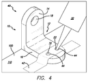
- FIGS. 1-7 show a bracket 10 in accordance with a preferred embodiment of the present invention.
- the bracket 10 generally includes a main body portion 12 with a first portion 14 and a second portion 16 that form a first angle A1 therebetween. Any angle between 1° and 180° is within the scope of the present invention.
- angle A1 is between about 45° and about 135°. In a more preferred embodiment angle A1 is between about 60° and about 120°. As shown in FIG. 1 , in the most preferred embodiment angle A1 is approximately 90°. However, this is not a limitation and different angles can be utilized for junctions between components with surfaces that meet at angles different than 90°.
- the first portion 14 includes opposing front and rear surfaces 14a and 14b and the second portion 16 includes opposing upper and lower surfaces 16a and 16b.
- the first portion 14 preferably includes at least one fastener opening 18 defined therethrough.
- the second portion 16 includes an insert feature 20 extending from the lower surface 16b and includes at least one and preferably two adhesive openings 22 defined therethrough.
- the insert feature 20 includes an alignment protrusion 24 formed or secured on the lower surface 16b of the second portion 16, a post 26 and a foot 28 on the distal end of the post 26.
- the post 26 extends between the alignment protrusion 24 and the foot 28.
- the alignment protrusion 24 can be omitted.
- the post and foot can be omitted and the alignment protrusion 24 can extend further downwardly from the lower surface 16b.
- the foot 28 can be positioned other than at the distal end of the post 26 (e.g., in the middle of the post 26).
- the adhesive openings 22 extend through the second portion 16 and the alignment protrusion 24.
- the insert feature 20 allows the bracket 10 to be bonded into a bracket opening 30 in a panel.
- the panel that includes the bracket opening(s) 30 will be referred to herein as the first component 100 as the bracket 10 can be used to join any two components together.
- the first component 100 can be a honeycomb panel.
- the insert feature 20 allows the bracket 10 to be bonded into different panels with different thicknesses.
- a panel includes opposing top and bottom surfaces, first and second opposing end edges, and first and second opposing side edges.
- the surfaces that are to be joined together are labeled 110 and the adjacent end or side surfaces are labeled 112.
- the second component or panel can be positioned such that the components together form a T-joint.
- FIGS. 3-4 shows a panel assembly or component assembly 40 that includes the first component 100 and the bracket 10.
- the bracket opening 30 in the first component 100 is formed in a shape.
- the alignment protrusion 24 has generally the same shape as the bracket opening 30. This provides installation alignment and orientation of the bracket 10 on the first component 100, when the insert feature 20 is inserted into the bracket opening 30.
- the alignment protrusion 24 has a generally triangular shape with rounded corners that provides a "snap" feel when inserted properly into the bracket opening 30 in the first component 100 with the corresponding shape.
- the alignment protrusion 24 and corresponding bracket opening 30 can have different corresponding shapes in different embodiments. In another embodiment, the shapes of the alignment protrusion 24 and the bracket opening 30 can be different. As shown in FIG. 3 , when the alignment protrusion 24 is properly inserted into the bracket opening 30, the rear surface 14b of the first portion 14 is aligned with an end surface 112 of first component 100.
- the adhesive openings 22 allow adhesive 32 to be injected therethrough and into the first component 100 for adhering the insert feature 20 and securing the bracket 10 to the first component 100.
- tape 42 which includes openings 44 that are coaxial with the adhesive openings 22, can be used to hold the bracket 10 in place during installation and adhesive 32 injection and while the adhesive 32 cures.
- the foot 28 is seated on a bottom surface of the bracket opening 30. In another embodiment, the foot 28 is not seated against the bottom surface.
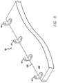
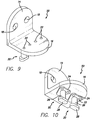
- FIG. 5 shows a plurality of brackets 10 secured to first component 100. It will be appreciated that several brackets 10 will typically be installed along a panel depending on load requirements, etc. The pitch/frequency of the brackets 10 can be adjusted according to load requirements.
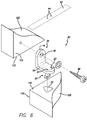
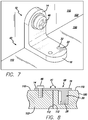
- FIGS. 6-7 show the component assembly 40 secured to a second component 102.
- a fastener 46 e.g., screw, bolt, rivet, nail, etc.
- the fastener opening 18 can include a countersink, if necessary.
- the fastener opening 18 is oversized (compared to the size of the fastener 46) to provide installation adjustment/tolerance.
- a quick release attachment can be provided instead of or in addition to the fastener opening 18.
- the first portion 14 can include an insert feature and adhesive openings just like the ones on the second portion.
- FIG. 8 shows an embodiment of a bracket 48 where angle A1 is 180°.
- the bracket 48 secures first and second components 100 and 102 that include co-planar surfaces 110 and are essentially positioned end-to-end to one another.
- the bracket 10 is made of metal.
- non-metal materials e.g., plastic, composites, wood are also within the scope of the present invention.
- a ductile material allows the load to be distributed to several different brackets 10 along the panel.
- a single bracket 50 can include multiple fastener openings 18 and/or multiple insert features 20 for higher load applications.
- bracket 10 can be used for installing/joining shelving, access covers, small parts, stoppers/bumpers, monuments, panels, or other parts within an aircraft. The bracket 10 can also be utilized outside of an aircraft interior.
- the invention may be defined by the following numbered aspects.
Landscapes
- Engineering & Computer Science (AREA)
- General Engineering & Computer Science (AREA)
- Mechanical Engineering (AREA)
- Standing Axle, Rod, Or Tube Structures Coupled By Welding, Adhesion, Or Deposition (AREA)
- Connection Of Plates (AREA)
Applications Claiming Priority (2)
| Application Number | Priority Date | Filing Date | Title |
|---|---|---|---|
| US201361903638P | 2013-11-13 | 2013-11-13 | |
| EP14861422.5A EP3068689B1 (de) | 2013-11-13 | 2014-11-13 | Flugzeuginnenraumklammer |
Related Parent Applications (2)
| Application Number | Title | Priority Date | Filing Date |
|---|---|---|---|
| EP14861422.5A Division EP3068689B1 (de) | 2013-11-13 | 2014-11-13 | Flugzeuginnenraumklammer |
| EP14861422.5A Division-Into EP3068689B1 (de) | 2013-11-13 | 2014-11-13 | Flugzeuginnenraumklammer |
Publications (2)
| Publication Number | Publication Date |
|---|---|
| EP3141766A1 true EP3141766A1 (de) | 2017-03-15 |
| EP3141766B1 EP3141766B1 (de) | 2018-03-28 |
Family
ID=53042908
Family Applications (2)
| Application Number | Title | Priority Date | Filing Date |
|---|---|---|---|
| EP16189539.6A Active EP3141766B1 (de) | 2013-11-13 | 2014-11-13 | Flugzeuginnenraumklammer |
| EP14861422.5A Active EP3068689B1 (de) | 2013-11-13 | 2014-11-13 | Flugzeuginnenraumklammer |
Family Applications After (1)
| Application Number | Title | Priority Date | Filing Date |
|---|---|---|---|
| EP14861422.5A Active EP3068689B1 (de) | 2013-11-13 | 2014-11-13 | Flugzeuginnenraumklammer |
Country Status (3)
| Country | Link |
|---|---|
| US (1) | US9279438B2 (de) |
| EP (2) | EP3141766B1 (de) |
| WO (1) | WO2015073621A1 (de) |
Families Citing this family (5)
| Publication number | Priority date | Publication date | Assignee | Title |
|---|---|---|---|---|
| DE102017102609A1 (de) | 2016-02-09 | 2017-08-10 | Comprisetec Gmbh | Verbindung von Bauteilen mittels Oberflächenstrukturen |
| US9726962B1 (en) * | 2016-04-29 | 2017-08-08 | Microsoft Technology Licensing, Llc | Enhanced camera module mount |
| JP2019527081A (ja) * | 2016-06-24 | 2019-09-26 | コーニンクレッカ フィリップス エヌ ヴェKoninklijke Philips N.V. | 垂直及び水平調整機能を持つブラケット |
| US10506876B1 (en) * | 2018-01-31 | 2019-12-17 | E-Make Co., Ltd. | Self-assembly cabinet |
| GB2582631A (en) * | 2019-03-28 | 2020-09-30 | Airbus Operations Ltd | A joint for an aircraft assembly |
Citations (6)
| Publication number | Priority date | Publication date | Assignee | Title |
|---|---|---|---|---|
| US3707062A (en) * | 1970-02-02 | 1972-12-26 | Fleetwood B Joiner Jr | Field application of thermosetting resin |
| US5007760A (en) * | 1988-07-28 | 1991-04-16 | Eastman Kodak Company | Device for aligning and mounting a copier or printer subsystem |
| EP0694701A1 (de) * | 1994-07-25 | 1996-01-31 | Alusuisse-Lonza Services AG | Verbindungselement |
| US20080131656A1 (en) * | 2006-12-05 | 2008-06-05 | Lockheed Martin Corporation | System, method, and apparatus for structural lug formed from a combination of metal and composite laminate materials |
| WO2013000591A1 (de) * | 2011-06-30 | 2013-01-03 | Johnson Controls Gmbh | Fügeverfahren zur stoffschlüssigen abschnittsweisen verbindung zumindest zweier bauteile |
| FR2986544A1 (fr) * | 2012-02-07 | 2013-08-09 | Techniwood | Systeme de fixation d'un panneau sur un element de structure porteuse |
Family Cites Families (14)
| Publication number | Priority date | Publication date | Assignee | Title |
|---|---|---|---|---|
| US3031217A (en) * | 1959-06-08 | 1962-04-24 | George A Tinnerman | Brackets and bracket anchoring devices |
| US3339609A (en) | 1965-08-02 | 1967-09-05 | Delron Company Inc | Floating nut insert |
| US3403641A (en) * | 1967-11-24 | 1968-10-01 | Richard J Smith | Brackets for assembling knockdown cabinets |
| US4062298A (en) * | 1976-11-10 | 1977-12-13 | Uop Inc. | Anti rattle track fitting |
| GB1579941A (en) * | 1977-02-03 | 1980-11-26 | Bicc Ltd | Screw fixing |
| GR63633B (en) * | 1977-09-27 | 1979-11-27 | H Fischer | Anchoring of one element of solide fiction for filling the blind hole with a hardening binding material |
| US4382416A (en) * | 1981-02-17 | 1983-05-10 | Kellogg Smith Ogden | Detachable nestable mast steps |
| US4932805A (en) | 1988-07-28 | 1990-06-12 | Eastman Kodak Company | Method and apparatus for aligning and mounting machine components |
| US5207043A (en) * | 1988-11-07 | 1993-05-04 | Mcgee Brian P | Masonry connector |
| US5240543A (en) * | 1990-06-11 | 1993-08-31 | Atr International, Inc. | Apparatus for and method of seating a fastener insert in a honeycomb panel |
| US5169062A (en) * | 1992-01-24 | 1992-12-08 | The Steel City Corporation | Newspaper delivery tube |
| US5846018A (en) * | 1996-08-26 | 1998-12-08 | Super Stud Building Products, Inc. | Deflection slide clip |
| IN2012DN06466A (de) | 2010-02-05 | 2015-10-09 | Bell Helicopter Textron Inc | |
| DE102011011113B4 (de) * | 2011-02-12 | 2013-01-31 | M.A.C.'s Holding Gmbh | Rahmensystem eines Partikelschutzgitters |
-
2014
- 2014-11-13 EP EP16189539.6A patent/EP3141766B1/de active Active
- 2014-11-13 US US14/540,195 patent/US9279438B2/en active Active
- 2014-11-13 EP EP14861422.5A patent/EP3068689B1/de active Active
- 2014-11-13 WO PCT/US2014/065366 patent/WO2015073621A1/en active Application Filing
Patent Citations (6)
| Publication number | Priority date | Publication date | Assignee | Title |
|---|---|---|---|---|
| US3707062A (en) * | 1970-02-02 | 1972-12-26 | Fleetwood B Joiner Jr | Field application of thermosetting resin |
| US5007760A (en) * | 1988-07-28 | 1991-04-16 | Eastman Kodak Company | Device for aligning and mounting a copier or printer subsystem |
| EP0694701A1 (de) * | 1994-07-25 | 1996-01-31 | Alusuisse-Lonza Services AG | Verbindungselement |
| US20080131656A1 (en) * | 2006-12-05 | 2008-06-05 | Lockheed Martin Corporation | System, method, and apparatus for structural lug formed from a combination of metal and composite laminate materials |
| WO2013000591A1 (de) * | 2011-06-30 | 2013-01-03 | Johnson Controls Gmbh | Fügeverfahren zur stoffschlüssigen abschnittsweisen verbindung zumindest zweier bauteile |
| FR2986544A1 (fr) * | 2012-02-07 | 2013-08-09 | Techniwood | Systeme de fixation d'un panneau sur un element de structure porteuse |
Also Published As
| Publication number | Publication date |
|---|---|
| EP3068689A1 (de) | 2016-09-21 |
| EP3068689B1 (de) | 2019-02-20 |
| EP3141766B1 (de) | 2018-03-28 |
| WO2015073621A1 (en) | 2015-05-21 |
| EP3068689A4 (de) | 2017-11-01 |
| US9279438B2 (en) | 2016-03-08 |
| US20150129728A1 (en) | 2015-05-14 |
Similar Documents
| Publication | Publication Date | Title |
|---|---|---|
| US9279438B2 (en) | Aircraft interior bracket | |
| US10781607B2 (en) | Handle load transfer insert for panels | |
| US10736416B2 (en) | Panels comprising a mechanical locking device and an assembled product comprising the panels | |
| US9638233B1 (en) | Fastener system | |
| US10260541B2 (en) | Panel systems and methods of assembling panel systems | |
| EP2892388B1 (de) | Selbstverriegelnde verbindungen für plattenstrukturen und verfahren zur herstellung davon | |
| US7527223B2 (en) | Interior panel attachment system | |
| EP3594513A1 (de) | Platten mit mechanischer verriegelungsvorrichtung und montiertes produkt mit den platten | |
| US10562632B2 (en) | Aircraft storage bin bucket with space efficient corner joint | |
| US10016955B2 (en) | Panel apparatus including multiple panels and mechanical fasteners and methods of assembling the panel apparatus | |
| US9943167B2 (en) | Trim profile covering fixture | |
| US20180195269A1 (en) | Panel assemblies and methods to assemble the same | |
| US20160347439A1 (en) | Fastening device | |
| EP3884174B1 (de) | Verbessertes verbindungssystem | |
| EP3166821B1 (de) | Bodensystem, fahrzeug, wie beispielsweise servicefahrzeuge mit einem solchen bodensystem und installation eines solchen bodensystems | |
| EP3199336A1 (de) | Sandwichplattenanordnung und verfahren | |
| US11199210B2 (en) | Self-retaining spacer and clip device | |
| US10994854B2 (en) | Aerodynamic aircraft wall comprising at least one vortex generator, and aircraft comprising the said aerodynamic wall | |
| CN102107810B (zh) | 电梯轿厢室、电梯侧板紧固装置及电梯轿厢室制造方法 | |
| US20190119904A1 (en) | Systems and methods for joining composite panels | |
| WO2007022580A1 (en) | Joining panels of sheet material |
Legal Events
| Date | Code | Title | Description |
|---|---|---|---|
| PUAI | Public reference made under article 153(3) epc to a published international application that has entered the european phase |
Free format text: ORIGINAL CODE: 0009012 |
|
| STAA | Information on the status of an ep patent application or granted ep patent |
Free format text: STATUS: THE APPLICATION HAS BEEN PUBLISHED |
|
| AC | Divisional application: reference to earlier application |
Ref document number: 3068689 Country of ref document: EP Kind code of ref document: P |
|
| AK | Designated contracting states |
Kind code of ref document: A1 Designated state(s): AL AT BE BG CH CY CZ DE DK EE ES FI FR GB GR HR HU IE IS IT LI LT LU LV MC MK MT NL NO PL PT RO RS SE SI SK SM TR |
|
| STAA | Information on the status of an ep patent application or granted ep patent |
Free format text: STATUS: REQUEST FOR EXAMINATION WAS MADE |
|
| 17P | Request for examination filed |
Effective date: 20170913 |
|
| RBV | Designated contracting states (corrected) |
Designated state(s): AL AT BE BG CH CY CZ DE DK EE ES FI FR GB GR HR HU IE IS IT LI LT LU LV MC MK MT NL NO PL PT RO RS SE SI SK SM TR |
|
| GRAP | Despatch of communication of intention to grant a patent |
Free format text: ORIGINAL CODE: EPIDOSNIGR1 |
|
| STAA | Information on the status of an ep patent application or granted ep patent |
Free format text: STATUS: GRANT OF PATENT IS INTENDED |
|
| RIC1 | Information provided on ipc code assigned before grant |
Ipc: F16B 5/06 20060101AFI20171201BHEP Ipc: F16B 11/00 20060101ALN20171201BHEP |
|
| INTG | Intention to grant announced |
Effective date: 20171220 |
|
| GRAS | Grant fee paid |
Free format text: ORIGINAL CODE: EPIDOSNIGR3 |
|
| GRAA | (expected) grant |
Free format text: ORIGINAL CODE: 0009210 |
|
| STAA | Information on the status of an ep patent application or granted ep patent |
Free format text: STATUS: THE PATENT HAS BEEN GRANTED |
|
| AC | Divisional application: reference to earlier application |
Ref document number: 3068689 Country of ref document: EP Kind code of ref document: P |
|
| AK | Designated contracting states |
Kind code of ref document: B1 Designated state(s): AL AT BE BG CH CY CZ DE DK EE ES FI FR GB GR HR HU IE IS IT LI LT LU LV MC MK MT NL NO PL PT RO RS SE SI SK SM TR |
|
| REG | Reference to a national code |
Ref country code: GB Ref legal event code: FG4D |
|
| REG | Reference to a national code |
Ref country code: CH Ref legal event code: EP |
|
| REG | Reference to a national code |
Ref country code: AT Ref legal event code: REF Ref document number: 983712 Country of ref document: AT Kind code of ref document: T Effective date: 20180415 |
|
| REG | Reference to a national code |
Ref country code: IE Ref legal event code: FG4D |
|
| REG | Reference to a national code |
Ref country code: DE Ref legal event code: R096 Ref document number: 602014023182 Country of ref document: DE |
|
| PG25 | Lapsed in a contracting state [announced via postgrant information from national office to epo] |
Ref country code: FI Free format text: LAPSE BECAUSE OF FAILURE TO SUBMIT A TRANSLATION OF THE DESCRIPTION OR TO PAY THE FEE WITHIN THE PRESCRIBED TIME-LIMIT Effective date: 20180328 Ref country code: NO Free format text: LAPSE BECAUSE OF FAILURE TO SUBMIT A TRANSLATION OF THE DESCRIPTION OR TO PAY THE FEE WITHIN THE PRESCRIBED TIME-LIMIT Effective date: 20180628 Ref country code: HR Free format text: LAPSE BECAUSE OF FAILURE TO SUBMIT A TRANSLATION OF THE DESCRIPTION OR TO PAY THE FEE WITHIN THE PRESCRIBED TIME-LIMIT Effective date: 20180328 Ref country code: LT Free format text: LAPSE BECAUSE OF FAILURE TO SUBMIT A TRANSLATION OF THE DESCRIPTION OR TO PAY THE FEE WITHIN THE PRESCRIBED TIME-LIMIT Effective date: 20180328 |
|
| REG | Reference to a national code |
Ref country code: NL Ref legal event code: MP Effective date: 20180328 |
|
| REG | Reference to a national code |
Ref country code: LT Ref legal event code: MG4D |
|
| PG25 | Lapsed in a contracting state [announced via postgrant information from national office to epo] |
Ref country code: RS Free format text: LAPSE BECAUSE OF FAILURE TO SUBMIT A TRANSLATION OF THE DESCRIPTION OR TO PAY THE FEE WITHIN THE PRESCRIBED TIME-LIMIT Effective date: 20180328 Ref country code: GR Free format text: LAPSE BECAUSE OF FAILURE TO SUBMIT A TRANSLATION OF THE DESCRIPTION OR TO PAY THE FEE WITHIN THE PRESCRIBED TIME-LIMIT Effective date: 20180629 Ref country code: LV Free format text: LAPSE BECAUSE OF FAILURE TO SUBMIT A TRANSLATION OF THE DESCRIPTION OR TO PAY THE FEE WITHIN THE PRESCRIBED TIME-LIMIT Effective date: 20180328 Ref country code: SE Free format text: LAPSE BECAUSE OF FAILURE TO SUBMIT A TRANSLATION OF THE DESCRIPTION OR TO PAY THE FEE WITHIN THE PRESCRIBED TIME-LIMIT Effective date: 20180328 Ref country code: BG Free format text: LAPSE BECAUSE OF FAILURE TO SUBMIT A TRANSLATION OF THE DESCRIPTION OR TO PAY THE FEE WITHIN THE PRESCRIBED TIME-LIMIT Effective date: 20180628 |
|
| PG25 | Lapsed in a contracting state [announced via postgrant information from national office to epo] |
Ref country code: ES Free format text: LAPSE BECAUSE OF FAILURE TO SUBMIT A TRANSLATION OF THE DESCRIPTION OR TO PAY THE FEE WITHIN THE PRESCRIBED TIME-LIMIT Effective date: 20180328 Ref country code: NL Free format text: LAPSE BECAUSE OF FAILURE TO SUBMIT A TRANSLATION OF THE DESCRIPTION OR TO PAY THE FEE WITHIN THE PRESCRIBED TIME-LIMIT Effective date: 20180328 Ref country code: AL Free format text: LAPSE BECAUSE OF FAILURE TO SUBMIT A TRANSLATION OF THE DESCRIPTION OR TO PAY THE FEE WITHIN THE PRESCRIBED TIME-LIMIT Effective date: 20180328 Ref country code: PL Free format text: LAPSE BECAUSE OF FAILURE TO SUBMIT A TRANSLATION OF THE DESCRIPTION OR TO PAY THE FEE WITHIN THE PRESCRIBED TIME-LIMIT Effective date: 20180328 Ref country code: RO Free format text: LAPSE BECAUSE OF FAILURE TO SUBMIT A TRANSLATION OF THE DESCRIPTION OR TO PAY THE FEE WITHIN THE PRESCRIBED TIME-LIMIT Effective date: 20180328 Ref country code: IT Free format text: LAPSE BECAUSE OF FAILURE TO SUBMIT A TRANSLATION OF THE DESCRIPTION OR TO PAY THE FEE WITHIN THE PRESCRIBED TIME-LIMIT Effective date: 20180328 Ref country code: EE Free format text: LAPSE BECAUSE OF FAILURE TO SUBMIT A TRANSLATION OF THE DESCRIPTION OR TO PAY THE FEE WITHIN THE PRESCRIBED TIME-LIMIT Effective date: 20180328 |
|
| PG25 | Lapsed in a contracting state [announced via postgrant information from national office to epo] |
Ref country code: CZ Free format text: LAPSE BECAUSE OF FAILURE TO SUBMIT A TRANSLATION OF THE DESCRIPTION OR TO PAY THE FEE WITHIN THE PRESCRIBED TIME-LIMIT Effective date: 20180328 Ref country code: SM Free format text: LAPSE BECAUSE OF FAILURE TO SUBMIT A TRANSLATION OF THE DESCRIPTION OR TO PAY THE FEE WITHIN THE PRESCRIBED TIME-LIMIT Effective date: 20180328 Ref country code: SK Free format text: LAPSE BECAUSE OF FAILURE TO SUBMIT A TRANSLATION OF THE DESCRIPTION OR TO PAY THE FEE WITHIN THE PRESCRIBED TIME-LIMIT Effective date: 20180328 |
|
| REG | Reference to a national code |
Ref country code: AT Ref legal event code: MK05 Ref document number: 983712 Country of ref document: AT Kind code of ref document: T Effective date: 20180328 |
|
| PG25 | Lapsed in a contracting state [announced via postgrant information from national office to epo] |
Ref country code: PT Free format text: LAPSE BECAUSE OF FAILURE TO SUBMIT A TRANSLATION OF THE DESCRIPTION OR TO PAY THE FEE WITHIN THE PRESCRIBED TIME-LIMIT Effective date: 20180730 |
|
| REG | Reference to a national code |
Ref country code: DE Ref legal event code: R097 Ref document number: 602014023182 Country of ref document: DE |
|
| PG25 | Lapsed in a contracting state [announced via postgrant information from national office to epo] |
Ref country code: DK Free format text: LAPSE BECAUSE OF FAILURE TO SUBMIT A TRANSLATION OF THE DESCRIPTION OR TO PAY THE FEE WITHIN THE PRESCRIBED TIME-LIMIT Effective date: 20180328 Ref country code: AT Free format text: LAPSE BECAUSE OF FAILURE TO SUBMIT A TRANSLATION OF THE DESCRIPTION OR TO PAY THE FEE WITHIN THE PRESCRIBED TIME-LIMIT Effective date: 20180328 |
|
| PLBE | No opposition filed within time limit |
Free format text: ORIGINAL CODE: 0009261 |
|
| STAA | Information on the status of an ep patent application or granted ep patent |
Free format text: STATUS: NO OPPOSITION FILED WITHIN TIME LIMIT |
|
| 26N | No opposition filed |
Effective date: 20190103 |
|
| PG25 | Lapsed in a contracting state [announced via postgrant information from national office to epo] |
Ref country code: SI Free format text: LAPSE BECAUSE OF FAILURE TO SUBMIT A TRANSLATION OF THE DESCRIPTION OR TO PAY THE FEE WITHIN THE PRESCRIBED TIME-LIMIT Effective date: 20180328 |
|
| REG | Reference to a national code |
Ref country code: CH Ref legal event code: PL |
|
| GBPC | Gb: european patent ceased through non-payment of renewal fee |
Effective date: 20181113 |
|
| PG25 | Lapsed in a contracting state [announced via postgrant information from national office to epo] |
Ref country code: MC Free format text: LAPSE BECAUSE OF FAILURE TO SUBMIT A TRANSLATION OF THE DESCRIPTION OR TO PAY THE FEE WITHIN THE PRESCRIBED TIME-LIMIT Effective date: 20180328 Ref country code: LU Free format text: LAPSE BECAUSE OF NON-PAYMENT OF DUE FEES Effective date: 20181113 |
|
| REG | Reference to a national code |
Ref country code: BE Ref legal event code: MM Effective date: 20181130 |
|
| REG | Reference to a national code |
Ref country code: IE Ref legal event code: MM4A |
|
| PG25 | Lapsed in a contracting state [announced via postgrant information from national office to epo] |
Ref country code: CH Free format text: LAPSE BECAUSE OF NON-PAYMENT OF DUE FEES Effective date: 20181130 Ref country code: LI Free format text: LAPSE BECAUSE OF NON-PAYMENT OF DUE FEES Effective date: 20181130 |
|
| PG25 | Lapsed in a contracting state [announced via postgrant information from national office to epo] |
Ref country code: IE Free format text: LAPSE BECAUSE OF NON-PAYMENT OF DUE FEES Effective date: 20181113 |
|
| PG25 | Lapsed in a contracting state [announced via postgrant information from national office to epo] |
Ref country code: BE Free format text: LAPSE BECAUSE OF NON-PAYMENT OF DUE FEES Effective date: 20181130 |
|
| PG25 | Lapsed in a contracting state [announced via postgrant information from national office to epo] |
Ref country code: GB Free format text: LAPSE BECAUSE OF NON-PAYMENT OF DUE FEES Effective date: 20181113 |
|
| PG25 | Lapsed in a contracting state [announced via postgrant information from national office to epo] |
Ref country code: MT Free format text: LAPSE BECAUSE OF NON-PAYMENT OF DUE FEES Effective date: 20181113 |
|
| PG25 | Lapsed in a contracting state [announced via postgrant information from national office to epo] |
Ref country code: TR Free format text: LAPSE BECAUSE OF FAILURE TO SUBMIT A TRANSLATION OF THE DESCRIPTION OR TO PAY THE FEE WITHIN THE PRESCRIBED TIME-LIMIT Effective date: 20180328 |
|
| PG25 | Lapsed in a contracting state [announced via postgrant information from national office to epo] |
Ref country code: CY Free format text: LAPSE BECAUSE OF FAILURE TO SUBMIT A TRANSLATION OF THE DESCRIPTION OR TO PAY THE FEE WITHIN THE PRESCRIBED TIME-LIMIT Effective date: 20180328 Ref country code: MK Free format text: LAPSE BECAUSE OF NON-PAYMENT OF DUE FEES Effective date: 20180328 Ref country code: HU Free format text: LAPSE BECAUSE OF FAILURE TO SUBMIT A TRANSLATION OF THE DESCRIPTION OR TO PAY THE FEE WITHIN THE PRESCRIBED TIME-LIMIT; INVALID AB INITIO Effective date: 20141113 |
|
| PG25 | Lapsed in a contracting state [announced via postgrant information from national office to epo] |
Ref country code: IS Free format text: LAPSE BECAUSE OF FAILURE TO SUBMIT A TRANSLATION OF THE DESCRIPTION OR TO PAY THE FEE WITHIN THE PRESCRIBED TIME-LIMIT Effective date: 20180728 |
|
| REG | Reference to a national code |
Ref country code: DE Ref legal event code: R081 Ref document number: 602014023182 Country of ref document: DE Owner name: SAFRAN CABIN INC. (N.D.GES.D. STAATES DELAWARE, US Free format text: FORMER OWNER: C&D ZODIAC, INC., HUNTINGTON BEACH, CALIF., US |
|
| PGFP | Annual fee paid to national office [announced via postgrant information from national office to epo] |
Ref country code: FR Payment date: 20231020 Year of fee payment: 10 Ref country code: DE Payment date: 20231019 Year of fee payment: 10 |