EP3141648A1 - Mounting member for wrapping and mounting a pollution control element - Google Patents
Mounting member for wrapping and mounting a pollution control element Download PDFInfo
- Publication number
- EP3141648A1 EP3141648A1 EP15184316.6A EP15184316A EP3141648A1 EP 3141648 A1 EP3141648 A1 EP 3141648A1 EP 15184316 A EP15184316 A EP 15184316A EP 3141648 A1 EP3141648 A1 EP 3141648A1
- Authority
- EP
- European Patent Office
- Prior art keywords
- mounting member
- pollution control
- mounting
- inorganic particles
- control element
- Prior art date
- Legal status (The legal status is an assumption and is not a legal conclusion. Google has not performed a legal analysis and makes no representation as to the accuracy of the status listed.)
- Granted
Links
Images

Classifications
-
- D—TEXTILES; PAPER
- D04—BRAIDING; LACE-MAKING; KNITTING; TRIMMINGS; NON-WOVEN FABRICS
- D04H—MAKING TEXTILE FABRICS, e.g. FROM FIBRES OR FILAMENTARY MATERIAL; FABRICS MADE BY SUCH PROCESSES OR APPARATUS, e.g. FELTS, NON-WOVEN FABRICS; COTTON-WOOL; WADDING ; NON-WOVEN FABRICS FROM STAPLE FIBRES, FILAMENTS OR YARNS, BONDED WITH AT LEAST ONE WEB-LIKE MATERIAL DURING THEIR CONSOLIDATION
- D04H1/00—Non-woven fabrics formed wholly or mainly of staple fibres or like relatively short fibres
- D04H1/40—Non-woven fabrics formed wholly or mainly of staple fibres or like relatively short fibres from fleeces or layers composed of fibres without existing or potential cohesive properties
- D04H1/413—Non-woven fabrics formed wholly or mainly of staple fibres or like relatively short fibres from fleeces or layers composed of fibres without existing or potential cohesive properties containing granules other than absorbent substances
-
- B—PERFORMING OPERATIONS; TRANSPORTING
- B01—PHYSICAL OR CHEMICAL PROCESSES OR APPARATUS IN GENERAL
- B01J—CHEMICAL OR PHYSICAL PROCESSES, e.g. CATALYSIS OR COLLOID CHEMISTRY; THEIR RELEVANT APPARATUS
- B01J21/00—Catalysts comprising the elements, oxides, or hydroxides of magnesium, boron, aluminium, carbon, silicon, titanium, zirconium, or hafnium
- B01J21/12—Silica and alumina
-
- B—PERFORMING OPERATIONS; TRANSPORTING
- B01—PHYSICAL OR CHEMICAL PROCESSES OR APPARATUS IN GENERAL
- B01J—CHEMICAL OR PHYSICAL PROCESSES, e.g. CATALYSIS OR COLLOID CHEMISTRY; THEIR RELEVANT APPARATUS
- B01J37/00—Processes, in general, for preparing catalysts; Processes, in general, for activation of catalysts
- B01J37/02—Impregnation, coating or precipitation
- B01J37/0201—Impregnation
- B01J37/0203—Impregnation the impregnation liquid containing organic compounds
-
- B—PERFORMING OPERATIONS; TRANSPORTING
- B01—PHYSICAL OR CHEMICAL PROCESSES OR APPARATUS IN GENERAL
- B01J—CHEMICAL OR PHYSICAL PROCESSES, e.g. CATALYSIS OR COLLOID CHEMISTRY; THEIR RELEVANT APPARATUS
- B01J37/00—Processes, in general, for preparing catalysts; Processes, in general, for activation of catalysts
- B01J37/02—Impregnation, coating or precipitation
- B01J37/0201—Impregnation
- B01J37/0213—Preparation of the impregnating solution
-
- B—PERFORMING OPERATIONS; TRANSPORTING
- B01—PHYSICAL OR CHEMICAL PROCESSES OR APPARATUS IN GENERAL
- B01J—CHEMICAL OR PHYSICAL PROCESSES, e.g. CATALYSIS OR COLLOID CHEMISTRY; THEIR RELEVANT APPARATUS
- B01J37/00—Processes, in general, for preparing catalysts; Processes, in general, for activation of catalysts
- B01J37/02—Impregnation, coating or precipitation
- B01J37/0236—Drying, e.g. preparing a suspension, adding a soluble salt and drying
-
- D—TEXTILES; PAPER
- D04—BRAIDING; LACE-MAKING; KNITTING; TRIMMINGS; NON-WOVEN FABRICS
- D04H—MAKING TEXTILE FABRICS, e.g. FROM FIBRES OR FILAMENTARY MATERIAL; FABRICS MADE BY SUCH PROCESSES OR APPARATUS, e.g. FELTS, NON-WOVEN FABRICS; COTTON-WOOL; WADDING ; NON-WOVEN FABRICS FROM STAPLE FIBRES, FILAMENTS OR YARNS, BONDED WITH AT LEAST ONE WEB-LIKE MATERIAL DURING THEIR CONSOLIDATION
- D04H1/00—Non-woven fabrics formed wholly or mainly of staple fibres or like relatively short fibres
- D04H1/40—Non-woven fabrics formed wholly or mainly of staple fibres or like relatively short fibres from fleeces or layers composed of fibres without existing or potential cohesive properties
- D04H1/42—Non-woven fabrics formed wholly or mainly of staple fibres or like relatively short fibres from fleeces or layers composed of fibres without existing or potential cohesive properties characterised by the use of certain kinds of fibres insofar as this use has no preponderant influence on the consolidation of the fleece
- D04H1/4209—Inorganic fibres
-
- D—TEXTILES; PAPER
- D04—BRAIDING; LACE-MAKING; KNITTING; TRIMMINGS; NON-WOVEN FABRICS
- D04H—MAKING TEXTILE FABRICS, e.g. FROM FIBRES OR FILAMENTARY MATERIAL; FABRICS MADE BY SUCH PROCESSES OR APPARATUS, e.g. FELTS, NON-WOVEN FABRICS; COTTON-WOOL; WADDING ; NON-WOVEN FABRICS FROM STAPLE FIBRES, FILAMENTS OR YARNS, BONDED WITH AT LEAST ONE WEB-LIKE MATERIAL DURING THEIR CONSOLIDATION
- D04H1/00—Non-woven fabrics formed wholly or mainly of staple fibres or like relatively short fibres
- D04H1/40—Non-woven fabrics formed wholly or mainly of staple fibres or like relatively short fibres from fleeces or layers composed of fibres without existing or potential cohesive properties
- D04H1/42—Non-woven fabrics formed wholly or mainly of staple fibres or like relatively short fibres from fleeces or layers composed of fibres without existing or potential cohesive properties characterised by the use of certain kinds of fibres insofar as this use has no preponderant influence on the consolidation of the fleece
- D04H1/4209—Inorganic fibres
- D04H1/4218—Glass fibres
-
- D—TEXTILES; PAPER
- D04—BRAIDING; LACE-MAKING; KNITTING; TRIMMINGS; NON-WOVEN FABRICS
- D04H—MAKING TEXTILE FABRICS, e.g. FROM FIBRES OR FILAMENTARY MATERIAL; FABRICS MADE BY SUCH PROCESSES OR APPARATUS, e.g. FELTS, NON-WOVEN FABRICS; COTTON-WOOL; WADDING ; NON-WOVEN FABRICS FROM STAPLE FIBRES, FILAMENTS OR YARNS, BONDED WITH AT LEAST ONE WEB-LIKE MATERIAL DURING THEIR CONSOLIDATION
- D04H1/00—Non-woven fabrics formed wholly or mainly of staple fibres or like relatively short fibres
- D04H1/40—Non-woven fabrics formed wholly or mainly of staple fibres or like relatively short fibres from fleeces or layers composed of fibres without existing or potential cohesive properties
- D04H1/42—Non-woven fabrics formed wholly or mainly of staple fibres or like relatively short fibres from fleeces or layers composed of fibres without existing or potential cohesive properties characterised by the use of certain kinds of fibres insofar as this use has no preponderant influence on the consolidation of the fleece
- D04H1/4209—Inorganic fibres
- D04H1/4242—Carbon fibres
-
- D—TEXTILES; PAPER
- D04—BRAIDING; LACE-MAKING; KNITTING; TRIMMINGS; NON-WOVEN FABRICS
- D04H—MAKING TEXTILE FABRICS, e.g. FROM FIBRES OR FILAMENTARY MATERIAL; FABRICS MADE BY SUCH PROCESSES OR APPARATUS, e.g. FELTS, NON-WOVEN FABRICS; COTTON-WOOL; WADDING ; NON-WOVEN FABRICS FROM STAPLE FIBRES, FILAMENTS OR YARNS, BONDED WITH AT LEAST ONE WEB-LIKE MATERIAL DURING THEIR CONSOLIDATION
- D04H1/00—Non-woven fabrics formed wholly or mainly of staple fibres or like relatively short fibres
- D04H1/40—Non-woven fabrics formed wholly or mainly of staple fibres or like relatively short fibres from fleeces or layers composed of fibres without existing or potential cohesive properties
- D04H1/44—Non-woven fabrics formed wholly or mainly of staple fibres or like relatively short fibres from fleeces or layers composed of fibres without existing or potential cohesive properties the fleeces or layers being consolidated by mechanical means, e.g. by rolling
- D04H1/46—Non-woven fabrics formed wholly or mainly of staple fibres or like relatively short fibres from fleeces or layers composed of fibres without existing or potential cohesive properties the fleeces or layers being consolidated by mechanical means, e.g. by rolling by needling or like operations to cause entanglement of fibres
-
- D—TEXTILES; PAPER
- D04—BRAIDING; LACE-MAKING; KNITTING; TRIMMINGS; NON-WOVEN FABRICS
- D04H—MAKING TEXTILE FABRICS, e.g. FROM FIBRES OR FILAMENTARY MATERIAL; FABRICS MADE BY SUCH PROCESSES OR APPARATUS, e.g. FELTS, NON-WOVEN FABRICS; COTTON-WOOL; WADDING ; NON-WOVEN FABRICS FROM STAPLE FIBRES, FILAMENTS OR YARNS, BONDED WITH AT LEAST ONE WEB-LIKE MATERIAL DURING THEIR CONSOLIDATION
- D04H1/00—Non-woven fabrics formed wholly or mainly of staple fibres or like relatively short fibres
- D04H1/40—Non-woven fabrics formed wholly or mainly of staple fibres or like relatively short fibres from fleeces or layers composed of fibres without existing or potential cohesive properties
- D04H1/44—Non-woven fabrics formed wholly or mainly of staple fibres or like relatively short fibres from fleeces or layers composed of fibres without existing or potential cohesive properties the fleeces or layers being consolidated by mechanical means, e.g. by rolling
- D04H1/46—Non-woven fabrics formed wholly or mainly of staple fibres or like relatively short fibres from fleeces or layers composed of fibres without existing or potential cohesive properties the fleeces or layers being consolidated by mechanical means, e.g. by rolling by needling or like operations to cause entanglement of fibres
- D04H1/48—Non-woven fabrics formed wholly or mainly of staple fibres or like relatively short fibres from fleeces or layers composed of fibres without existing or potential cohesive properties the fleeces or layers being consolidated by mechanical means, e.g. by rolling by needling or like operations to cause entanglement of fibres in combination with at least one other method of consolidation
- D04H1/488—Non-woven fabrics formed wholly or mainly of staple fibres or like relatively short fibres from fleeces or layers composed of fibres without existing or potential cohesive properties the fleeces or layers being consolidated by mechanical means, e.g. by rolling by needling or like operations to cause entanglement of fibres in combination with at least one other method of consolidation in combination with bonding agents
-
- D—TEXTILES; PAPER
- D04—BRAIDING; LACE-MAKING; KNITTING; TRIMMINGS; NON-WOVEN FABRICS
- D04H—MAKING TEXTILE FABRICS, e.g. FROM FIBRES OR FILAMENTARY MATERIAL; FABRICS MADE BY SUCH PROCESSES OR APPARATUS, e.g. FELTS, NON-WOVEN FABRICS; COTTON-WOOL; WADDING ; NON-WOVEN FABRICS FROM STAPLE FIBRES, FILAMENTS OR YARNS, BONDED WITH AT LEAST ONE WEB-LIKE MATERIAL DURING THEIR CONSOLIDATION
- D04H1/00—Non-woven fabrics formed wholly or mainly of staple fibres or like relatively short fibres
- D04H1/40—Non-woven fabrics formed wholly or mainly of staple fibres or like relatively short fibres from fleeces or layers composed of fibres without existing or potential cohesive properties
- D04H1/58—Non-woven fabrics formed wholly or mainly of staple fibres or like relatively short fibres from fleeces or layers composed of fibres without existing or potential cohesive properties by applying, incorporating or activating chemical or thermoplastic bonding agents, e.g. adhesives
- D04H1/64—Non-woven fabrics formed wholly or mainly of staple fibres or like relatively short fibres from fleeces or layers composed of fibres without existing or potential cohesive properties by applying, incorporating or activating chemical or thermoplastic bonding agents, e.g. adhesives the bonding agent being applied in wet state, e.g. chemical agents in dispersions or solutions
-
- F—MECHANICAL ENGINEERING; LIGHTING; HEATING; WEAPONS; BLASTING
- F01—MACHINES OR ENGINES IN GENERAL; ENGINE PLANTS IN GENERAL; STEAM ENGINES
- F01N—GAS-FLOW SILENCERS OR EXHAUST APPARATUS FOR MACHINES OR ENGINES IN GENERAL; GAS-FLOW SILENCERS OR EXHAUST APPARATUS FOR INTERNAL-COMBUSTION ENGINES
- F01N3/00—Exhaust or silencing apparatus having means for purifying, rendering innocuous, or otherwise treating exhaust
- F01N3/08—Exhaust or silencing apparatus having means for purifying, rendering innocuous, or otherwise treating exhaust for rendering innocuous
- F01N3/10—Exhaust or silencing apparatus having means for purifying, rendering innocuous, or otherwise treating exhaust for rendering innocuous by thermal or catalytic conversion of noxious components of exhaust
- F01N3/24—Exhaust or silencing apparatus having means for purifying, rendering innocuous, or otherwise treating exhaust for rendering innocuous by thermal or catalytic conversion of noxious components of exhaust characterised by constructional aspects of converting apparatus
- F01N3/28—Construction of catalytic reactors
- F01N3/2839—Arrangements for mounting catalyst support in housing, e.g. with means for compensating thermal expansion or vibration
- F01N3/2853—Arrangements for mounting catalyst support in housing, e.g. with means for compensating thermal expansion or vibration using mats or gaskets between catalyst body and housing
-
- F—MECHANICAL ENGINEERING; LIGHTING; HEATING; WEAPONS; BLASTING
- F01—MACHINES OR ENGINES IN GENERAL; ENGINE PLANTS IN GENERAL; STEAM ENGINES
- F01N—GAS-FLOW SILENCERS OR EXHAUST APPARATUS FOR MACHINES OR ENGINES IN GENERAL; GAS-FLOW SILENCERS OR EXHAUST APPARATUS FOR INTERNAL-COMBUSTION ENGINES
- F01N3/00—Exhaust or silencing apparatus having means for purifying, rendering innocuous, or otherwise treating exhaust
- F01N3/08—Exhaust or silencing apparatus having means for purifying, rendering innocuous, or otherwise treating exhaust for rendering innocuous
- F01N3/10—Exhaust or silencing apparatus having means for purifying, rendering innocuous, or otherwise treating exhaust for rendering innocuous by thermal or catalytic conversion of noxious components of exhaust
- F01N3/24—Exhaust or silencing apparatus having means for purifying, rendering innocuous, or otherwise treating exhaust for rendering innocuous by thermal or catalytic conversion of noxious components of exhaust characterised by constructional aspects of converting apparatus
- F01N3/28—Construction of catalytic reactors
- F01N3/2839—Arrangements for mounting catalyst support in housing, e.g. with means for compensating thermal expansion or vibration
- F01N3/2853—Arrangements for mounting catalyst support in housing, e.g. with means for compensating thermal expansion or vibration using mats or gaskets between catalyst body and housing
- F01N3/2857—Arrangements for mounting catalyst support in housing, e.g. with means for compensating thermal expansion or vibration using mats or gaskets between catalyst body and housing the mats or gaskets being at least partially made of intumescent material, e.g. unexpanded vermiculite
-
- D—TEXTILES; PAPER
- D10—INDEXING SCHEME ASSOCIATED WITH SUBLASSES OF SECTION D, RELATING TO TEXTILES
- D10B—INDEXING SCHEME ASSOCIATED WITH SUBLASSES OF SECTION D, RELATING TO TEXTILES
- D10B2101/00—Inorganic fibres
- D10B2101/10—Inorganic fibres based on non-oxides other than metals
-
- D—TEXTILES; PAPER
- D10—INDEXING SCHEME ASSOCIATED WITH SUBLASSES OF SECTION D, RELATING TO TEXTILES
- D10B—INDEXING SCHEME ASSOCIATED WITH SUBLASSES OF SECTION D, RELATING TO TEXTILES
- D10B2101/00—Inorganic fibres
- D10B2101/10—Inorganic fibres based on non-oxides other than metals
- D10B2101/14—Carbides; Nitrides; Silicides; Borides
- D10B2101/16—Silicon carbide
-
- D—TEXTILES; PAPER
- D10—INDEXING SCHEME ASSOCIATED WITH SUBLASSES OF SECTION D, RELATING TO TEXTILES
- D10B—INDEXING SCHEME ASSOCIATED WITH SUBLASSES OF SECTION D, RELATING TO TEXTILES
- D10B2505/00—Industrial
- D10B2505/04—Filters
-
- F—MECHANICAL ENGINEERING; LIGHTING; HEATING; WEAPONS; BLASTING
- F01—MACHINES OR ENGINES IN GENERAL; ENGINE PLANTS IN GENERAL; STEAM ENGINES
- F01N—GAS-FLOW SILENCERS OR EXHAUST APPARATUS FOR MACHINES OR ENGINES IN GENERAL; GAS-FLOW SILENCERS OR EXHAUST APPARATUS FOR INTERNAL-COMBUSTION ENGINES
- F01N2310/00—Selection of sound absorbing or insulating material
- F01N2310/02—Mineral wool, e.g. glass wool, rock wool, asbestos or the like
Definitions
- the invention relates to a mounting member for wrapping and mounting a pollution control element in a casing of a pollution control device, the mounting member comprising inorganic fiber material and inorganic particles.
- the invention also relates to a method of manufacturing a mounting member for wrapping and mounting a pollution control element in a casing of a pollution control device.
- Exhaust gas cleaning systems using a ceramic catalytic converter are known as means for removing carbon monoxide (CO), hydrocarbons (HC), and nitrogen oxides (NOx) and the like that are included in exhaust gas from automobile engines.
- the ceramic catalytic converter generally stores a ceramic catalyst carrier with a honeycomb shape or the like in a metal casing.
- Other exhaust gas cleaning systems contain ceramic particulate filters for removing particulates from the exhaust gas of diesel or gasoline engines.
- Ceramic catalytic converters There are various types of ceramic catalytic converters, but a general form provides a catalyst carrier or a filter, a casing that stores the catalyst carrier or the filter, and a thermal insulation member that fills the gap between the outer surface of the catalyst carrier or the filter and the inner surface of the casing.
- the thermal insulation member mounts the catalyst carrier or the filter and prevents mechanical shock due to impact and vibration and the like from being inadvertently applied to the catalyst carrier or the filter. Thereby, moving and breaking of the catalyst carrier or the filter can be sufficiently suppressed, and thus the desired effect can be provided over a long period of time.
- This type of thermal insulation member is also commonly called a mounting member because the member has a function of mounting a pollution control element such as a catalyst carrier or a filter in a metal shell or the like.
- JP 2002 206 421 A2 discloses a holding and sealing material for a catalytic converter, that can sufficiently maintain the function of retaining the pollution control element in a pollution control device at high temperatures.
- the holding and mounting material comprises ceramic fibers.
- the fibers comprise an uneven structure consisting of inorganic particles added to the fibers by sintering.
- WO 2012/106295 A1 discloses a mounting member that can sufficiently suppress scattering of inorganic fiber material when a pollution control element is assembled in a casing, and that can maintain sufficiently high contact pressure between the inner surface of the casing and the pollution control element.
- the mounting member provides a mat made from inorganic fiber material and an aggregated substance containing an organic binder and inorganic fine particles that is impregnated throughout most of the mat.
- US 8,071,040 B2 discloses a mounting mat for an exhaust gas treatment device including high temperature resistant ceramic fibers containing alumina and/or high temperature resistant biosoluble inorganic fibers, organic binder which at least partially liquefies at elevated temperature prior to binder burnout, colloidal inorganic oxide and optionally intumescent material.
- the mounting mat can be easily installed and can function across a wide range of inlet gas temperatures without a significant loss in mat thickness and corresponding shear strength and holding pressure performance.
- This behavior may lead to a lower than expected mounted density of the mounting member and thus to lower contact pressure of the mounting member (mat) during the use of the pollution control device.
- a potential compensation of this effect by using a mounting member with a higher area weight adds cost to the system.
- the width of a mounting member for a pollution control element is typically adopted to cover the length of the ceramic element of the pollution control device either completely or a significant portion of it.
- the elongation of a mounting member needs to be taken into account to avoid that the mounting member extends over the edge of the ceramic element after assembly.
- a lower elongation allows the use of wider mounting members leading to higher holding force of the ceramic element in the metallic shell.
- an object of the invention to provide a mounting member that on the one side can sufficiently maintain the function of retaining the pollution control element in a pollution control device during its use across wide temperature ranges and that on the other side has an improved behaviour during the assembly of the pollution control device, e.g. provides a reduced elongation during canning.
- the reduction of the elongation helps to reduce the amount of the relative expensive inorganic fiber material and on the other hand to ensure a high enough mount density.
- the particle size is defined as DV 50, which is the median particle diameter on a volumetric basis, i.e. 50% by volume of the particles are smaller than this diameter and 50% are larger.
- the diameters are measured according to DIN ISO 13320.
- the positive effect in elongation may also reduce the waste during production and may therefore provide a cost benefit.
- the inorganic fiber material of the mounting member may comprise fibers selected from the group of glass fibers, ceramic fibers, carbon fibers, silicon carbide fibers or boron fibers or a combination thereof.
- Other fibers are possible as well as long as they withstand the high temperatures occurring in a pollution control device and the required holding forces during use of the pollution control device.
- the inorganic fiber material may be needle punched.
- Other ways of compressing the inorganic fiber material may be used as well such as for example stitch-bonding, resin bonding, applying pressure and/or combinations thereof.
- the inorganic particles are selected from the group consisting of metal oxides, metal hydroxides, metal oxide hydroxides, silicates, clays, nitrides, carbides, sulphides, carbonates and combinations thereof. They may for example be selected from DispalTM particles from Sasol Corporation, USA. With DispalTM 23N4-80 and DispalTM 18N4-80 particles from Sasol Corporation, USA very good results have been achieved as will be explained in the example section of this patent application.
- the mount member may contain organic binder up to 3 wt. %. It is also possible to achieve good results without any binder, as shown in the examples. But the use of binder may under certain conditions lead to better results of the elongation. The amount of binder used needs to be optimized regarding the ability to sufficiently hold the pollution control element within the pollution control device during use.
- the inorganic particles may get impregnated through the mat by using a water base slurry containing the inorganic particles.
- a water base slurry containing the inorganic particles An easy way of distributing the particles throughout the mat is to prepare a slurry, for example a water based slurry and apply the slurry onto the mat.
- the slurry needs to be of a concentration that allows the particles to migrate throughout most of the mat. If the slurry is too concentrated, which means if the concentration of particles within the slurry is too high, the risk exists, that the particles stay on the surface of the mounting member and do not migrate into the mounting member. It is also possible to distribute the particles within the mounting member during the fiber laying process by mixing the particles with the fibers before laying them to a mat.
- the slurry may contain at least 80 wt. %, preferably 90 wt. % and more preferably 95 wt. % of water.
- the slurry may also contain an organic binder.
- the organic binder may comprise at least one of polymers or copolymers of acrylate, methacrylate, styrene, butadiene, vinyl pyridine, acrylonitrile, vinyl chloride, vinyl acetate, vinyl alcohol or ethylene, polyurethane, polyamides, silicones, polyesters, epoxy resins, or combinations thereof.
- concentration of the inorganic particles within the mounting member may be between 0.5 and 5 wt. %, preferred between 1.0 and 2.5 wt. %.
- the maximum reduction of mount density of a mounting member according to the invention may be 3 % caused by an elongation of the mounting member during stuffing at a calculated mount density of 0.4 g/cm 3 .
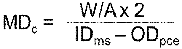
- the calculated mount density of the mounting member in the pollution control device (assuming no mat elongation) is calculated by dividing the weight per area 2 times by the difference between metal shell inner diameter minus the pollution control element outer diameter. The following formula illustrates the calculation:
- the mounting member may extend over the pollution control element due to its elongation during the canning process. This portion of the mat is cut off and weighed. This cut off weight is subtracted from the original mat weight and the reduced weight per area of the mat after canning is calculated based on its original dimension. The mount density after canning is calculated using the weight per area after canning. The mount density difference is calculated in percent of the calculated mount density. The following formula illustrates the calculation:
- the mounting member may comprise intumescent material disposed in the mat member.
- intumescent material means a material that expands, foams, or swells when exposed to a sufficient amount of thermal energy.
- Useful intumescent materials for use in making an intumescent mounting member may include, but are not limited to, unexpanded vermiculite ore, treated unexpanded vermiculite ore, partially dehydrated vermiculite ore, expandable graphite, mixtures of expandable graphite with treated or untreated unexpanded vermiculite ore, processed expandable sodium silicate, for example EXPANTROLTM insoluble sodium silicate, commercially available from 3M Company, St. Paul, Minn., and mixtures thereof.
- Another example of a desirable commercially available expandable graphite material is GRAFOILTM Grade 338-50 expandable graphite flake, from UCAR Carbon Co., Inc., Cleveland, Ohio.
- the invention also relates to a method of manufacturing a mounting member for wrapping and mounting a pollution control element in a casing of a pollution control device comprising the following steps:
- the method according to the invention may also comprise a drying step after the impregnating step.
- the drying may be done by room temperature or by elevated temperatures, such as for example temperatures between 100°C and 180°C.
- the drying may also be done by using an air stream.
- the slurry used for the method according to the invention may contain an organic binder.
- the invention relates to the use of inorganic particles for producing a mounting member for wrapping and mounting a pollution control element in a casing of a pollution control device, wherein the average diameter of the fine particles ranges from DV 50 of 800 nm to 15000 nm measured according to DIN ISO 13320, preferably from DV 50 of 1000 nm to 15000 nm according to DIN ISO 13320.
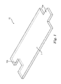
- Fig. 1 is a perspective view illustrating an example of the mounting member of the present invention.
- the mounting member 10 illustrated in this figure may be wrapped around a pollution control element 30 having for example a round cylindrical or elliptical cylindrical outer shape, in order to retain the element in a casing 20 (refer to Fig. 2 ). All other shapes of the pollution control element 30 are possible as well.
- the mounting member 10 has a length that is in accordance with the length of the outer circumference of the pollution control element 30.
- the mounting member 10 has a convex part 10a and a concave part 10b on another end, for example, and has a shape such that the convex part 10a and the concave part 10b mutually engage when the mounting member 10 is wrapped around the pollution control element 30, but the shape for the mating is not restricted in particular, and any shape that can effectively prevent leaking of the exhaust gas in the mating region is acceptable, and other shapes such as an L shape are also possible.
- the mounting member 10 has also a width that is in accordance with the length of the pollution control element 30.
- the width of the mounting member 10 needs to take into account an elongation of the mounting member 10 that might occur, when the mounting member 10 being wrapped around the pollution control element 30 gets stuffed into the casing 20, to avoid that the mounting member 10 after stuffing extends over the edge of the pollution control element 30.
- Fig. 2 shows the mounting member 10 that is used to retain the pollution control element 30 in a pollution control device 50.
- a specific example of the pollution control element 30 is a catalyst carrier or a filter element or the like that is used for cleaning the exhaust gas from an engine.
- Specific examples of the pollution control device 50 include catalytic converters and exhaust cleaning devices (for example, a particulate filter device).
- the pollution control device 50 illustrated in Fig. 2 has a casing 20, a pollution control element 30 provided in the casing 20, and a mounting member 10 provided between the inner surface of the casing 20 and the outer surface of the pollution control element 30.
- the pollution control device 50 also has a gas intake port 21 where the exhaust gases are introduced to the pollution control element 30, and a gas discharge port 22 where the exhaust gas that has passed through the pollution control element 30 is discharged.
- the width of the gap between the inner surface of the casing 20 and the outer surface of the pollution control element 30 may be between 1.5 to 15 mm, preferably 3 to 10 mm.
- the mounting member 10 is preferably in an appropriately compressed condition to achieve a suitable bulk density between the casing 20 and the pollution control element 30.
- All examples are based on alumina-silica fiber blankets from Mitsubishi Plastics Inc. (Maftec MLS2).
- the mats are spray impregnated with a slurry of inorganic particles.
- an additional an organic latex binder was added to the slurry in addition to the inorganic particles.
- the impregnated mats were dried and then tested. The tests include multi-cycle compression testing at elevated temperatures and hard stuffing tests to determine the mat elongation.
- Inorganic particles DispalTM 23N4-80, DispalTM 18N4-80 both from Sasol Corporation, 12120 Wickchester Lane, Houston TX 77079, USA
- Organic binder AcronalTM A273S from BASF SE, Ludwigshafen, Germany.
- Inorganic particles SnowtexTM OS; Nissan Chemical Industries, Japan; Colloidal Alumina; Nissan Chemical Industries, Japan Organic binder: NipolTM LX 874; Nippon Zeon Co., Japan
- the slurries for impregnation were prepared by adding the inorganic particles to water in an amount according to the below table and stirring with a laboratory mixer for 5 minutes. In some samples (see also below table) additional organic binder was added afterwards and was stirred for 1 additional minute.
- a sheet of the MLS 2 blanket was cut into pieces and impregnated by spraying the above described slurry containing the DispalTM 23N4-80 particles, particle size 1.87 nm (DV 50) measured according to DIN ISO 13320, onto the blanket. After the liquid was impregnated into the blanket in this manner, drying was performed in a forced air dryer for 15 minutes at 150°C air temperature. The impregnated and dried mounting member contained about 1.5 % by weight of the particles.
- a sheet of the MLS 2 blanket was cut into pieces and impregnated by spraying the above described slurry containing the DispalTM 23N4-80 particles, particle size 1.87 nm (DV 50) measured according to DIN ISO 13320, and the organic binder AcronalTM A273S, onto the blanket. After the liquid was impregnated into the blanket in this manner, drying was performed in a forced air dryer for 15 minutes at 150°C air temperature.
- the impregnated and dried mounting member contained about 1.5% by weight of the inorganic particles and 0.8% by weight organic binder.
- a sheet of the MLS 2 blanket was cut into pieces and impregnated by spraying the above described slurry containing the DispalTM 18N4-80 particles, particle size 3.51 nm (DV 50) measured according to DIN ISO 13320, onto the blanket. After the liquid was impregnated into the blanket in this manner, drying was performed in a forced air dryer for 15 minutes at 150°C air temperature. The impregnated and dried mounting member contained about 1.5% by weight of the particles.
- a sheet of the MLS 2 blanket was cut into pieces and impregnated by spraying the above described slurry containing the DispalTM 18N4-80 particles, particle size 3.51 nm (DV 50) measured according to DIN ISO 13320, and the organic binder AcronalTM A273S, onto the blanket. After the liquid was impregnated into the blanket in this manner, drying was performed in a forced air dryer for 15 minutes at 150°C air temperature. The impregnated and dried mounting member contained about 1.5% by weight of the particles and 0.8% by weight of the organic binder.
- MLS 2 blanket without any treatment was cut into pieces and used as comparative example 1a.
- the mounting density was adapted to the mounting density of examples 1 and 2.
- MLS 2 blanket without any treatment was cut into pieces and used as comparative example 1 b.
- the mounting density was adapted to the mounting density of examples 3 and 4.
- a comparative sample was prepared by adding inorganic colloid particles (SnowtexTM OS, produced by Nissan Chemical Industries, Ltd.) 68.55 g and 2.0 g organic binder (NipolTM LX874, produced by Nippon Zeon Co., Ltd.) to 1429.50g Water and stirring for 5 minutes.
- the inorganic colloidal particles had a particle size of 16.9 nm (DV 50) measured according to DIN ISO 13320.
- a needle punched alumina fiber blanket (produced by Mitsubishi Plastics, Inc.) was impregnated by spraying the above described slurry onto the blanket. After the liquid was impregnated into the blanket in this manner, drying was performed for 15 minutes using a forced air dryer with the temperature set to 150°C.
- a second liquid containing inorganic colloid particles and organic binder was prepared by adding 63g of colloidal silica (SnowtexTM OS) and 10g NipolTM LX874 to 65g of water and stirring for 1 minute.
- the second liquid was coated to both an upper and lower surface of the blanket that had been impregnated before with the first liquid.
- the amount of 7g/m 2 of colloid silica was sprayed onto both surfaces and the total amount of organic binder was 0.8%.
- the impregnated material was dried for 5 minutes in a forced air dryer with temperature set to 150°C.
- a first liquid containing colloidal particles and organic binder was prepared by adding 201g of colloidal alumina (alumina sol, produced by Nissan Chemical Industries, Ltd.) and 3.99g organic binder (NipolTM LX874, produced by Nippon Zeon Co., Ltd.) to 2790g Water and stirring for 5 minutes.
- the inorganic colloidal particles had a particle size of 0.76 nm (DV 50) measured according to DIN ISO 13320.
- a needle punched alumina fiber blanket (produced by Mitsubishi Plastics, Inc.) was impregnated by spraying the above described slurry onto the blanket. After the liquid was impregnated into the blanket in this manner, drying was performed for 15 minutes using a forced air dryer with the temperature set to 150°C.
- a second liquid containing inorganic colloid particles and organic binder was prepared by adding 63g of colloidal silica (SnowtexTM OS) and 10g NipolTM LX874 to 65g of water and stirring for 1 minute.
- the second liquid was coated to both an upper and lower surface of the blanket that had been impregnated before with the first liquid.
- the amount of 7g/m 2 of colloid silica was sprayed onto both surfaces and the total amount of organic binder was 0.8%.
- the impregnated material was dried for 5 minutes in a forced air dryer with temperature set to 150°C.
- a further comparative sample was prepared by adding inorganic colloid particles (SnowtexTM OS, produced by Nissan Chemical Industries, Ltd.) 68.55g and 2.0g organic binder (NipolTM LX874, produced by Nippon Zeon Co., Ltd.) to 1429.50g Water and stirring for 5 minutes.
- the inorganic colloidal particles had a particle size of 16.9 nm (DV 50) measured according to DIN ISO 13320.
- a needle punched alumina fiber blanket (produced by Mitsubishi Plastics, Inc.) was impregnated by spraying the above described slurry onto the blanket. After the liquid was impregnated into the blanket in this manner, drying was performed for 15 minutes using a forced air dryer with the temperature set to 150°C.
- the particle size is determined with laser diffraction according to DIN ISO 13320: 2009(E).
- the particle size is defined as DV50, which is the median particle diameter on a volumetric basis, i.e. 50% by volume of the particles are smaller than this diameter and 50% are larger.
- the multi-cycle compression test is frequently used to design applications.
- the Examples were tested at a temperature of 650°C, the gap was cycled 1000 times between a closed gap and an open gap density. The open gap pressure after cycling is recorded.
- a material test machine from Zwick/Roell Model Z010 from Zwick Gmbh & Co KG, Ulm, Germany was utilized.
- the test machine was equipped with a lower fixed heatable stainless steel block and a load cell capable of measuring forces up to 10 kN and an upper heatable stainless steel block mounted to the movable crosshead of the test machine.
- a sample of each example and comparative example with 50.8 mm diameter was cut out of the mounting member and placed on the lower heatable stainless steel block.
- the crosshead was moved downwards to compress the mounting member to a defined closed gap, which corresponds to a density of the mounting member of 0.366 g/cm 3 .
- the temperature of the heatable stainless steel blocks was raised to 650°C while keeping the gap constant. After reaching the temperature of 650°C, the gap was cycled between the closed gap position corresponding to a density of the mounting member of 0.366 g/cm 3 and an open gap position corresponding to a density of the mounting member of 0.329 g/cm 3 . After 1000 cycles the test was stopped and the open gap pressure after 1000 cycles was recorded.
- Hard stuffing experiments were conducted to determine the elongation of the mounting members.
- the area weight of the mounting members, the metal shell inner diameter, and the pollution control element outer diameter were chosen to achieve a desired calculated mount density.
- the metal shell was calibrated using a shrinking machine from the company Wecotech, Gähwil, Switzerland.
- the transition angle between the inner shell diameter at the entrance side and the calibrated inner diameter was kept between 14° and 16°, in order to ensure consistent conditions for each example.
- the mounting members were cut so that they covered the complete length of the pollution control element.
- the mounting members were wrapped around the corresponding pollution control element and the stuffing was performed using a stuffing funnel with a contraction of 1.6°.
- a compression test machine MTS Alliance RT/30 from MTS, Eden Prairie, MN, USA was utilized to push the pollution control element together with the mounting member into the metal shell at a defined speed of 500 mm/min.
- the mat After stuffing the mat extended over the pollution control element due to the elongation during the stuffing process. This portion of the mat was cut and weighed to determine the effective mount density of the mat in the pollution control device.
Landscapes
- Engineering & Computer Science (AREA)
- Chemical & Material Sciences (AREA)
- Chemical Kinetics & Catalysis (AREA)
- Textile Engineering (AREA)
- Mechanical Engineering (AREA)
- Inorganic Chemistry (AREA)
- Organic Chemistry (AREA)
- Materials Engineering (AREA)
- Combustion & Propulsion (AREA)
- Health & Medical Sciences (AREA)
- Toxicology (AREA)
- General Engineering & Computer Science (AREA)
- General Chemical & Material Sciences (AREA)
- Dispersion Chemistry (AREA)
- Exhaust Gas After Treatment (AREA)
- Catalysts (AREA)
- Nonwoven Fabrics (AREA)
- Sealing Material Composition (AREA)
Description
- The invention relates to a mounting member for wrapping and mounting a pollution control element in a casing of a pollution control device, the mounting member comprising inorganic fiber material and inorganic particles. The invention also relates to a method of manufacturing a mounting member for wrapping and mounting a pollution control element in a casing of a pollution control device.
- Exhaust gas cleaning systems using a ceramic catalytic converter are known as means for removing carbon monoxide (CO), hydrocarbons (HC), and nitrogen oxides (NOx) and the like that are included in exhaust gas from automobile engines. Basically, the ceramic catalytic converter generally stores a ceramic catalyst carrier with a honeycomb shape or the like in a metal casing. Other exhaust gas cleaning systems contain ceramic particulate filters for removing particulates from the exhaust gas of diesel or gasoline engines.
- There are various types of ceramic catalytic converters, but a general form provides a catalyst carrier or a filter, a casing that stores the catalyst carrier or the filter, and a thermal insulation member that fills the gap between the outer surface of the catalyst carrier or the filter and the inner surface of the casing. The thermal insulation member mounts the catalyst carrier or the filter and prevents mechanical shock due to impact and vibration and the like from being inadvertently applied to the catalyst carrier or the filter. Thereby, moving and breaking of the catalyst carrier or the filter can be sufficiently suppressed, and thus the desired effect can be provided over a long period of time. This type of thermal insulation member is also commonly called a mounting member because the member has a function of mounting a pollution control element such as a catalyst carrier or a filter in a metal shell or the like.
-
JP 2002 206 421 A2 -
WO 2012/106295 A1 discloses a mounting member that can sufficiently suppress scattering of inorganic fiber material when a pollution control element is assembled in a casing, and that can maintain sufficiently high contact pressure between the inner surface of the casing and the pollution control element. The mounting member provides a mat made from inorganic fiber material and an aggregated substance containing an organic binder and inorganic fine particles that is impregnated throughout most of the mat. -
US 8,071,040 B2 discloses a mounting mat for an exhaust gas treatment device including high temperature resistant ceramic fibers containing alumina and/or high temperature resistant biosoluble inorganic fibers, organic binder which at least partially liquefies at elevated temperature prior to binder burnout, colloidal inorganic oxide and optionally intumescent material. The mounting mat can be easily installed and can function across a wide range of inlet gas temperatures without a significant loss in mat thickness and corresponding shear strength and holding pressure performance. - The above cited documents deal with improved behavior of mounting members during its use in a pollution control device especially with improved holding or contact pressure of the mounting member and with reducing fiber scattering. None of the documents deals with the problem of reducing the elongation of a mounting member during the assembly of a pollution control device. Elongation of a mounting member is the length difference between the mat width after assembly in a pollution control device and the width of the virgin mat.
- This behavior may lead to a lower than expected mounted density of the mounting member and thus to lower contact pressure of the mounting member (mat) during the use of the pollution control device. A potential compensation of this effect by using a mounting member with a higher area weight adds cost to the system.
- The width of a mounting member for a pollution control element is typically adopted to cover the length of the ceramic element of the pollution control device either completely or a significant portion of it. The elongation of a mounting member needs to be taken into account to avoid that the mounting member extends over the edge of the ceramic element after assembly. A lower elongation allows the use of wider mounting members leading to higher holding force of the ceramic element in the metallic shell.
- In view of the above it is an object of the invention to provide a mounting member that on the one side can sufficiently maintain the function of retaining the pollution control element in a pollution control device during its use across wide temperature ranges and that on the other side has an improved behaviour during the assembly of the pollution control device, e.g. provides a reduced elongation during canning. The reduction of the elongation helps to reduce the amount of the relative expensive inorganic fiber material and on the other hand to ensure a high enough mount density.
- With the invention it has been found that a mounting member for wrapping and mounting a pollution control element in a casing of a pollution control device with the following features
- inorganic fiber material; and
- inorganic particles, wherein the inorganic particles are distributed throughout most of the mounting member and comprise an average diameter of
DV 50 of 800 nm to 15000 nm measured according to DIN ISO 13320, preferably 1000 nm to 15000 nm provides excellent performance during the use of a pollution control device and has a reduced elongation during canning. - The particle size is defined as
DV 50, which is the median particle diameter on a volumetric basis, i.e. 50% by volume of the particles are smaller than this diameter and 50% are larger. The diameters are measured according to DIN ISO 13320. - It has been found a mounting member for wrapping and mounting a pollution control element in a casing of a pollution control device with inorganic particles being distributed throughout most of the mounting member, wherein the size of the particles is in the claimed range provides an improved elongation during mounting the pollution control device while still showing sufficient retaining forces of the pollution control element in a pollution control device during its use across wide temperature ranges. The positive effect in elongation may also reduce the waste during production and may therefore provide a cost benefit.
- According to one embodiment, the inorganic fiber material of the mounting member may comprise fibers selected from the group of glass fibers, ceramic fibers, carbon fibers, silicon carbide fibers or boron fibers or a combination thereof. Other fibers are possible as well as long as they withstand the high temperatures occurring in a pollution control device and the required holding forces during use of the pollution control device.
- According to another embodiment of the invention, the inorganic fiber material may be needle punched. Other ways of compressing the inorganic fiber material may be used as well such as for example stitch-bonding, resin bonding, applying pressure and/or combinations thereof.
- According to another embodiment of the invention, the inorganic particles are selected from the group consisting of metal oxides, metal hydroxides, metal oxide hydroxides, silicates, clays, nitrides, carbides, sulphides, carbonates and combinations thereof. They may for example be selected from Dispal™ particles from Sasol Corporation, USA. With Dispal™ 23N4-80 and Dispal™ 18N4-80 particles from Sasol Corporation, USA very good results have been achieved as will be explained in the example section of this patent application.
- According to one embodiment the mount member may contain organic binder up to 3 wt. %. It is also possible to achieve good results without any binder, as shown in the examples. But the use of binder may under certain conditions lead to better results of the elongation. The amount of binder used needs to be optimized regarding the ability to sufficiently hold the pollution control element within the pollution control device during use.
- According to another embodiment, the inorganic particles may get impregnated through the mat by using a water base slurry containing the inorganic particles. An easy way of distributing the particles throughout the mat is to prepare a slurry, for example a water based slurry and apply the slurry onto the mat. The slurry needs to be of a concentration that allows the particles to migrate throughout most of the mat. If the slurry is too concentrated, which means if the concentration of particles within the slurry is too high, the risk exists, that the particles stay on the surface of the mounting member and do not migrate into the mounting member. It is also possible to distribute the particles within the mounting member during the fiber laying process by mixing the particles with the fibers before laying them to a mat.
- The slurry may contain at least 80 wt. %, preferably 90 wt. % and more preferably 95 wt. % of water. The slurry may also contain an organic binder.
- The organic binder may comprise at least one of polymers or copolymers of acrylate, methacrylate, styrene, butadiene, vinyl pyridine, acrylonitrile, vinyl chloride, vinyl acetate, vinyl alcohol or ethylene, polyurethane, polyamides, silicones, polyesters, epoxy resins, or combinations thereof.
- Furthermore the concentration of the inorganic particles within the mounting member may be between 0.5 and 5 wt. %, preferred between 1.0 and 2.5 wt. %.
- According to yet another embodiment, the maximum reduction of mount density of a mounting member according to the invention may be 3 % caused by an elongation of the mounting member during stuffing at a calculated mount density of 0.4 g/cm3. The calculated mount density of the mounting member in the pollution control device (assuming no mat elongation) is calculated by dividing the weight per area 2 times by the difference between metal shell inner diameter minus the pollution control element outer diameter. The following formula illustrates the calculation:
- MDc - calculated mount density
- W/Am - weight per area or area weight of mounting member (mat)
- IDms - metal shell inner diameter
- ODpce - pollution control element outer diameter
- Wtm - weight of (mat)
- Lm - length of mat
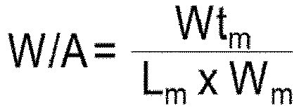
- Wm - width of mat (= length of pollution control element)
- whereby W/A is calculated as follows:
- Calculation of the mount density reduction: After canning the mounting member may extend over the pollution control element due to its elongation during the canning process. This portion of the mat is cut off and weighed. This cut off weight is subtracted from the original mat weight and the reduced weight per area of the mat after canning is calculated based on its original dimension. The mount density after canning is calculated using the weight per area after canning. The mount density difference is calculated in percent of the calculated mount density. The following formula illustrates the calculation:
- MDred - mount density reduction
- MDac - mount density after canning
- Wtem - weight of mat extended over the edge of the pollution control element after canning


- The mounting member may comprise intumescent material disposed in the mat member. As used herein, "intumescent material" means a material that expands, foams, or swells when exposed to a sufficient amount of thermal energy. Useful intumescent materials for use in making an intumescent mounting member may include, but are not limited to, unexpanded vermiculite ore, treated unexpanded vermiculite ore, partially dehydrated vermiculite ore, expandable graphite, mixtures of expandable graphite with treated or untreated unexpanded vermiculite ore, processed expandable sodium silicate, for example EXPANTROL™ insoluble sodium silicate, commercially available from 3M Company, St. Paul, Minn., and mixtures thereof. Another example of a desirable commercially available expandable graphite material is GRAFOIL™ Grade 338-50 expandable graphite flake, from UCAR Carbon Co., Inc., Cleveland, Ohio.
- The invention also relates to a method of manufacturing a mounting member for wrapping and mounting a pollution control element in a casing of a pollution control device comprising the following steps:
- preparing a water based slurry containing fine inorganic particles with an
average diameter DV 50 of 800 nm to 15000 nm measured according to DIN ISO 13320, preferablyDV 50 of 1000 nm to 15000 nm measured according to DIN ISO 13320; and - impregnating a mat containing inorganic fiber material with the slurry.
- The method according to the invention may also comprise a drying step after the impregnating step. The drying may be done by room temperature or by elevated temperatures, such as for example temperatures between 100°C and 180°C. The drying may also be done by using an air stream.
- The slurry used for the method according to the invention may contain an organic binder.
- And finally the invention relates to the use of inorganic particles for producing a mounting member for wrapping and mounting a pollution control element in a casing of a pollution control device, wherein the average diameter of the fine particles ranges from
DV 50 of 800 nm to 15000 nm measured according to DIN ISO 13320, preferably fromDV 50 of 1000 nm to 15000 nm according to DIN ISO 13320. - The invention will now be described in more detail with reference to the following Figures exemplifying particular embodiments of the invention:
- Fig. 1
- is a perspective view illustrating the retaining material according to an embodiment of the present invention;
- Fig. 2
- is a cross-sectional view schematically illustrating the pollution control device according to an embodiment of the present invention.
- Herein below various embodiments of the present invention are described and shown in the drawings wherein like elements are provided with the same reference numbers.
-
Fig. 1 is a perspective view illustrating an example of the mounting member of the present invention. The mountingmember 10 illustrated in this figure may be wrapped around apollution control element 30 having for example a round cylindrical or elliptical cylindrical outer shape, in order to retain the element in a casing 20 (refer toFig. 2 ). All other shapes of thepollution control element 30 are possible as well. The mountingmember 10 has a length that is in accordance with the length of the outer circumference of thepollution control element 30. The mountingmember 10 has aconvex part 10a and aconcave part 10b on another end, for example, and has a shape such that theconvex part 10a and theconcave part 10b mutually engage when the mountingmember 10 is wrapped around thepollution control element 30, but the shape for the mating is not restricted in particular, and any shape that can effectively prevent leaking of the exhaust gas in the mating region is acceptable, and other shapes such as an L shape are also possible. The mountingmember 10 has also a width that is in accordance with the length of thepollution control element 30. As already pointed out above the width of the mountingmember 10 needs to take into account an elongation of the mountingmember 10 that might occur, when the mountingmember 10 being wrapped around thepollution control element 30 gets stuffed into thecasing 20, to avoid that the mountingmember 10 after stuffing extends over the edge of thepollution control element 30. -
Fig. 2 shows the mountingmember 10 that is used to retain thepollution control element 30 in apollution control device 50. A specific example of thepollution control element 30 is a catalyst carrier or a filter element or the like that is used for cleaning the exhaust gas from an engine. Specific examples of thepollution control device 50 include catalytic converters and exhaust cleaning devices (for example, a particulate filter device). - The
pollution control device 50 illustrated inFig. 2 has acasing 20, apollution control element 30 provided in thecasing 20, and a mountingmember 10 provided between the inner surface of thecasing 20 and the outer surface of thepollution control element 30. Thepollution control device 50 also has agas intake port 21 where the exhaust gases are introduced to thepollution control element 30, and agas discharge port 22 where the exhaust gas that has passed through thepollution control element 30 is discharged. - The width of the gap between the inner surface of the
casing 20 and the outer surface of thepollution control element 30 may be between 1.5 to 15 mm, preferably 3 to 10 mm. The mountingmember 10 is preferably in an appropriately compressed condition to achieve a suitable bulk density between thecasing 20 and thepollution control element 30. By using the mountingmember 10 according to the invention to retain thepollution control element 30, a sufficiently high surface pressure can be maintained between the inner surface of thecasing 20 and thepollution control element 30. Furthermore, the elongation during the mounting of the pollution control element into the pollution control device can be reduced as compared to conventional mounting members, and therefore the usage amount of the relative expensive inorganic fiber material can be reduced. - The present invention is described while referencing examples. Note that the present invention is in no way restricted by these examples.
- All examples are based on alumina-silica fiber blankets from Mitsubishi Plastics Inc. (Maftec MLS2). The mats are spray impregnated with a slurry of inorganic particles. In some examples an additional an organic latex binder was added to the slurry in addition to the inorganic particles. The impregnated mats were dried and then tested. The tests include multi-cycle compression testing at elevated temperatures and hard stuffing tests to determine the mat elongation.
- Inorganic particles: Dispal™ 23N4-80, Dispal™ 18N4-80 both from Sasol Corporation, 12120 Wickchester Lane, Houston TX 77079, USA
Organic binder: Acronal™ A273S from BASF SE, Ludwigshafen, Germany. - Inorganic particles: Snowtex™ OS; Nissan Chemical Industries, Japan; Colloidal Alumina; Nissan Chemical Industries, Japan
Organic binder: Nipol™ LX 874; Nippon Zeon Co., Japan - The slurries for impregnation were prepared by adding the inorganic particles to water in an amount according to the below table and stirring with a laboratory mixer for 5 minutes. In some samples (see also below table) additional organic binder was added afterwards and was stirred for 1 additional minute.

- A sheet of the MLS 2 blanket was cut into pieces and impregnated by spraying the above described slurry containing the Dispal™ 23N4-80 particles, particle size 1.87 nm (DV 50) measured according to DIN ISO 13320, onto the blanket. After the liquid was impregnated into the blanket in this manner, drying was performed in a forced air dryer for 15 minutes at 150°C air temperature. The impregnated and dried mounting member contained about 1.5 % by weight of the particles.
- A sheet of the MLS 2 blanket was cut into pieces and impregnated by spraying the above described slurry containing the Dispal™ 23N4-80 particles, particle size 1.87 nm (DV 50) measured according to DIN ISO 13320, and the organic binder Acronal™ A273S, onto the blanket. After the liquid was impregnated into the blanket in this manner, drying was performed in a forced air dryer for 15 minutes at 150°C air temperature. The impregnated and dried mounting member contained about 1.5% by weight of the inorganic particles and 0.8% by weight organic binder.
- A sheet of the MLS 2 blanket was cut into pieces and impregnated by spraying the above described slurry containing the Dispal™ 18N4-80 particles, particle size 3.51 nm (DV 50) measured according to DIN ISO 13320, onto the blanket. After the liquid was impregnated into the blanket in this manner, drying was performed in a forced air dryer for 15 minutes at 150°C air temperature. The impregnated and dried mounting member contained about 1.5% by weight of the particles.
- A sheet of the MLS 2 blanket was cut into pieces and impregnated by spraying the above described slurry containing the Dispal™ 18N4-80 particles, particle size 3.51 nm (DV 50) measured according to DIN ISO 13320, and the organic binder Acronal™ A273S, onto the blanket. After the liquid was impregnated into the blanket in this manner, drying was performed in a forced air dryer for 15 minutes at 150°C air temperature. The impregnated and dried mounting member contained about 1.5% by weight of the particles and 0.8% by weight of the organic binder.
- MLS 2 blanket without any treatment was cut into pieces and used as comparative example 1a. For the stuffing and multi-cycle tests, the mounting density was adapted to the mounting density of examples 1 and 2.
- MLS 2 blanket without any treatment was cut into pieces and used as comparative example 1 b. For the stuffing and multi-cycle tests, the mounting density was adapted to the mounting density of examples 3 and 4.
- A comparative sample was prepared by adding inorganic colloid particles (Snowtex™ OS, produced by Nissan Chemical Industries, Ltd.) 68.55 g and 2.0 g organic binder (Nipol™ LX874, produced by Nippon Zeon Co., Ltd.) to 1429.50g Water and stirring for 5 minutes. The inorganic colloidal particles had a particle size of 16.9 nm (DV 50) measured according to DIN ISO 13320. A needle punched alumina fiber blanket (produced by Mitsubishi Plastics, Inc.) was impregnated by spraying the above described slurry onto the blanket. After the liquid was impregnated into the blanket in this manner, drying was performed for 15 minutes using a forced air dryer with the temperature set to 150°C.
- A second liquid containing inorganic colloid particles and organic binder was prepared by adding 63g of colloidal silica (Snowtex™ OS) and 10g Nipol™ LX874 to 65g of water and stirring for 1 minute. The second liquid was coated to both an upper and lower surface of the blanket that had been impregnated before with the first liquid. In total the amount of 7g/m2 of colloid silica was sprayed onto both surfaces and the total amount of organic binder was 0.8%. The impregnated material was dried for 5 minutes in a forced air dryer with temperature set to 150°C.
- A first liquid containing colloidal particles and organic binder was prepared by adding 201g of colloidal alumina (alumina sol, produced by Nissan Chemical Industries, Ltd.) and 3.99g organic binder (Nipol™ LX874, produced by Nippon Zeon Co., Ltd.) to 2790g Water and stirring for 5 minutes. The inorganic colloidal particles had a particle size of 0.76 nm (DV 50) measured according to DIN ISO 13320. A needle punched alumina fiber blanket (produced by Mitsubishi Plastics, Inc.) was impregnated by spraying the above described slurry onto the blanket. After the liquid was impregnated into the blanket in this manner, drying was performed for 15 minutes using a forced air dryer with the temperature set to 150°C.
- A second liquid containing inorganic colloid particles and organic binder was prepared by adding 63g of colloidal silica (Snowtex™ OS) and 10g Nipol™ LX874 to 65g of water and stirring for 1 minute. The second liquid was coated to both an upper and lower surface of the blanket that had been impregnated before with the first liquid. In total the amount of 7g/m2 of colloid silica was sprayed onto both surfaces and the total amount of organic binder was 0.8%. The impregnated material was dried for 5 minutes in a forced air dryer with temperature set to 150°C.
- A further comparative sample was prepared by adding inorganic colloid particles (Snowtex™ OS, produced by Nissan Chemical Industries, Ltd.) 68.55g and 2.0g organic binder (Nipol™ LX874, produced by Nippon Zeon Co., Ltd.) to 1429.50g Water and stirring for 5 minutes. The inorganic colloidal particles had a particle size of 16.9 nm (DV 50) measured according to DIN ISO 13320. A needle punched alumina fiber blanket (produced by Mitsubishi Plastics, Inc.) was impregnated by spraying the above described slurry onto the blanket. After the liquid was impregnated into the blanket in this manner, drying was performed for 15 minutes using a forced air dryer with the temperature set to 150°C.
- The particle size is determined with laser diffraction according to DIN ISO 13320: 2009(E). The particle size is defined as DV50, which is the median particle diameter on a volumetric basis, i.e. 50% by volume of the particles are smaller than this diameter and 50% are larger.
- The multi-cycle compression test is frequently used to design applications. The Examples were tested at a temperature of 650°C, the gap was cycled 1000 times between a closed gap and an open gap density. The open gap pressure after cycling is recorded.
- For the tests in these examples a material test machine from Zwick/Roell Model Z010 from Zwick Gmbh & Co KG, Ulm, Germany was utilized. The test machine was equipped with a lower fixed heatable stainless steel block and a load cell capable of measuring forces up to 10 kN and an upper heatable stainless steel block mounted to the movable crosshead of the test machine. For the tests a sample of each example and comparative example with 50.8 mm diameter was cut out of the mounting member and placed on the lower heatable stainless steel block. The crosshead was moved downwards to compress the mounting member to a defined closed gap, which corresponds to a density of the mounting member of 0.366 g/cm3. The temperature of the heatable stainless steel blocks was raised to 650°C while keeping the gap constant. After reaching the temperature of 650°C, the gap was cycled between the closed gap position corresponding to a density of the mounting member of 0.366 g/cm3 and an open gap position corresponding to a density of the mounting member of 0.329 g/cm3. After 1000 cycles the test was stopped and the open gap pressure after 1000 cycles was recorded.
- Hard stuffing experiments were conducted to determine the elongation of the mounting members. The area weight of the mounting members, the metal shell inner diameter, and the pollution control element outer diameter were chosen to achieve a desired calculated mount density. The metal shell was calibrated using a shrinking machine from the company Wecotech, Gähwil, Switzerland. The transition angle between the inner shell diameter at the entrance side and the calibrated inner diameter was kept between 14° and 16°, in order to ensure consistent conditions for each example.
- The mounting members were cut so that they covered the complete length of the pollution control element. The mounting members were wrapped around the corresponding pollution control element and the stuffing was performed using a stuffing funnel with a contraction of 1.6°. A compression test machine MTS Alliance RT/30 from MTS, Eden Prairie, MN, USA was utilized to push the pollution control element together with the mounting member into the metal shell at a defined speed of 500 mm/min.
- After stuffing the mat extended over the pollution control element due to the elongation during the stuffing process. This portion of the mat was cut and weighed to determine the effective mount density of the mat in the pollution control device.
- In the following table the particle diameters of all examples and comparative examples are shown as well as the measured elongation and the results of the multi-cycle compression test:


- The results show:
- It can be seen from the table above, that the examples 1 to 4 with the inorganic particles distributed through the mat show less elongation than the comparative example 1 a and 1 b. Comparative examples 2, 3 and 4 failed completely during the canning, the mats did not slide into the can and were destroyed. For these mounting members no elongation could be measured.
- The results show also that the examples 1 and 2, with 1.5% Dispal™ 23N4-80 show the higher results in the multi-cycle compression test. The open gap pressure after 1000 cycles for Examples 3 and 4 is lower than the one for comparative example 1 a or 1 b but they are still acceptable.
Claims (17)
- A mounting member for wrapping and mounting a pollution control element in a casing of a pollution control device, the mounting member comprising:- inorganic fiber material; and- inorganic particles, wherein the inorganic particles are distributed throughout most of the mounting member and comprise an average diameter of 800 nm to 15000 nm (DV 50) measured according to DIN ISO 13320, preferably of 1000 nm to 15000 nm (DV 50) measured according to DIN ISO 13320.
- The mounting member according to claim 1 wherein the inorganic fiber material comprises fibers selected from the group of glass fibers, ceramic fibers, carbon fibers, silicon carbide fibers or boron fibers or a combination thereof.
- The mounting member according to claim 1 or 2, wherein the inorganic fiber material of the mounting member is needle-punched.
- The mounting member according to any of the preceding claims, wherein the inorganic particles are selected from the group consisting of metal oxides, metal hydroxides, metal oxide hydroxides, silicates, clays, nitrides, carbides, sulphides, carbonates and combinations thereof.
- The mounting mat according to any of the preceding claims, wherein the inorganic particles are selected from Dispal™ particles from Sasol Corporation, USA.
- The mounting member according to any of the preceding claims, wherein the mounting member contains organic binder up to 3 wt. %.
- The mounting member according to any of the preceding claims, wherein the inorganic particles get impregnated through the mat by using a water based slurry containing the inorganic particles.
- The mounting member according to claim 7, wherein the slurry contains at least 80 wt. % water, preferably 90 wt. % water and more preferably 95 wt. % water.
- The mounting member according to claim 7 or claim 8, wherein the slurry contains an organic binder.
- The mounting member according to claim 9, wherein the organic binder comprises at least one of polymers or copolymers of acrylate, methacrylate, styrene, butadiene, vinyl pyridine, acrylonitrile, vinyl chloride, vinyl acetate, vinyl alcohol or ethylene, polyurethane, polyamides, silicones, polyesters, epoxy resins, or combinations thereof.
- The mounting member according to any of the preceding claims, wherein the concentration of the inorganic particles within the mounting member is between 0.5 and 5 wt. %, preferred between 1.0 and 2.5 wt. %.
- A mounting member according to any of the preceding claims, having a maximum reduction of the mount density of 3% caused by elongation of the mounting member during stuffing at a calculated mount density of 0.4 g/cm3.).
- The mounting member according to any of the preceding claims, wherein the mounting member comprises intumescent material disposed in the mounting member.
- Method of manufacturing a mounting member for wrapping and mounting a pollution control element in a casing of a pollution control device, comprising the following steps:preparing a water based slurry containing fine inorganic particles with an average diameter of 800 nm to 15000 nm (DV 50) measured according to DIN ISO 13320, preferably of 1000 nm to 15000 nm (DV 50) measured according to DIN ISO 13320;impregnating a mat containing inorganic fiber material with the slurry.
- The method according to claim 14, wherein the method comprises a drying step after the impregnating step.
- The method according to claim 14 or claim 15, wherein the slurry contains an organic binder.
- Use of inorganic particles for producing a mounting member for wrapping and mounting a pollution control element in a casing of a pollution control device, wherein the average diameter of the fine particles ranges from of 800 nm to 15000 nm (DV 50) measured according to DIN ISO 13320, preferably from of 1000 nm to 15000 nm (DV 50) according to DIN ISO 13320.
Priority Applications (10)
| Application Number | Priority Date | Filing Date | Title |
|---|---|---|---|
| PL15184316T PL3141648T3 (en) | 2015-09-08 | 2015-09-08 | Mounting member for wrapping and mounting a pollution control element |
| EP15184316.6A EP3141648B1 (en) | 2015-09-08 | 2015-09-08 | Mounting member for wrapping and mounting a pollution control element |
| CA2997945A CA2997945A1 (en) | 2015-09-08 | 2016-09-07 | Mounting member for wrapping and mounting a pollution control element |
| CN201680051886.XA CN108026678B (en) | 2015-09-08 | 2016-09-07 | Mounting elements for wrapping and installing pollution control elements |
| JP2018531309A JP6938502B2 (en) | 2015-09-08 | 2016-09-07 | Mounting member for winding around pollution prevention elements |
| MX2018002867A MX2018002867A (en) | 2015-09-08 | 2016-09-07 | Mounting member for wrapping and mounting a pollution control element. |
| KR1020187009302A KR20180048977A (en) | 2015-09-08 | 2016-09-07 | Mounting member for wrapping and mounting contamination control element |
| US15/757,738 US11969709B2 (en) | 2015-09-08 | 2016-09-07 | Mounting member for wrapping and mounting a pollution control element |
| PCT/US2016/050493 WO2017044451A1 (en) | 2015-09-08 | 2016-09-07 | Mounting member for wrapping and mounting a pollution control element |
| ZA2018/02263A ZA201802263B (en) | 2015-09-08 | 2018-04-06 | Mounting member for wrapping and mounting a pollution control element |
Applications Claiming Priority (1)
| Application Number | Priority Date | Filing Date | Title |
|---|---|---|---|
| EP15184316.6A EP3141648B1 (en) | 2015-09-08 | 2015-09-08 | Mounting member for wrapping and mounting a pollution control element |
Publications (2)
| Publication Number | Publication Date |
|---|---|
| EP3141648A1 true EP3141648A1 (en) | 2017-03-15 |
| EP3141648B1 EP3141648B1 (en) | 2018-07-18 |
Family
ID=54072715
Family Applications (1)
| Application Number | Title | Priority Date | Filing Date |
|---|---|---|---|
| EP15184316.6A Active EP3141648B1 (en) | 2015-09-08 | 2015-09-08 | Mounting member for wrapping and mounting a pollution control element |
Country Status (10)
| Country | Link |
|---|---|
| US (1) | US11969709B2 (en) |
| EP (1) | EP3141648B1 (en) |
| JP (1) | JP6938502B2 (en) |
| KR (1) | KR20180048977A (en) |
| CN (1) | CN108026678B (en) |
| CA (1) | CA2997945A1 (en) |
| MX (1) | MX2018002867A (en) |
| PL (1) | PL3141648T3 (en) |
| WO (1) | WO2017044451A1 (en) |
| ZA (1) | ZA201802263B (en) |
Families Citing this family (1)
| Publication number | Priority date | Publication date | Assignee | Title |
|---|---|---|---|---|
| JP7555781B2 (en) * | 2020-10-14 | 2024-09-25 | イビデン株式会社 | Inorganic fiber assembly with inorganic sheet material, method for producing inorganic fiber assembly with inorganic sheet material, and exhaust gas purification device |
Citations (7)
| Publication number | Priority date | Publication date | Assignee | Title |
|---|---|---|---|---|
| CH653288A5 (en) * | 1980-12-09 | 1985-12-31 | Micafil Ag | Bonded mat for plastic reinforcement |
| WO2000017121A1 (en) * | 1998-09-24 | 2000-03-30 | Rockwool International A/S | Man-made vitreous fibre products for use in thermal insulation, and their production |
| JP2002206421A (en) | 2001-01-11 | 2002-07-26 | Ibiden Co Ltd | Holding-seal material for catalytic converter, ceramic fiber, and method of manufacturing the ceramic fiber |
| US20110247839A1 (en) * | 2010-04-13 | 2011-10-13 | 3M Innovative Properties Company | Inorganic fiber webs and methods of making and using |
| US8071040B2 (en) | 2009-09-23 | 2011-12-06 | Unifax I LLC | Low shear mounting mat for pollution control devices |
| WO2012106295A1 (en) | 2011-01-31 | 2012-08-09 | 3M Innovative Properties Company | Mounting member for pollution control element, manufacturing method thereof, and pollution control device |
| WO2014160665A1 (en) * | 2013-03-27 | 2014-10-02 | 3M Innovative Properties Company | Thermally insulated components |
Family Cites Families (26)
| Publication number | Priority date | Publication date | Assignee | Title |
|---|---|---|---|---|
| CN1270056C (en) * | 1997-02-06 | 2006-08-16 | 美国3M公司 | Pollution control device |
| US6403526B1 (en) * | 1999-12-21 | 2002-06-11 | W. R. Grace & Co.-Conn. | Alumina trihydrate derived high pore volume, high surface area aluminum oxide composites and methods of their preparation and use |
| EP1418317A4 (en) | 2001-05-25 | 2008-03-05 | Ibiden Co Ltd | Alumina-silica-based fiber, ceramic fiber, ceramic fiber complex, retaining sealmaterial, production method thereof, and alumina fiber complex production method |
| JP4376565B2 (en) | 2003-07-15 | 2009-12-02 | ニチアス株式会社 | Catalytic converter holding material and catalytic converter |
| JP2005074243A (en) | 2003-08-29 | 2005-03-24 | Three M Innovative Properties Co | Contamination controlling element-holding material and contamination controlling apparatus |
| KR101117039B1 (en) | 2003-08-29 | 2012-03-15 | 다우 글로벌 테크놀로지스 엘엘씨 | Improved diesel exhaust filter |
| JP4849891B2 (en) | 2003-11-05 | 2012-01-11 | イビデン株式会社 | Manufacturing method of honeycomb structure |
| KR101058770B1 (en) | 2004-06-29 | 2011-08-24 | 유니프랙스 아이 엘엘씨 | Exhaust gas treatment device and method for making the same |
| JP2006223920A (en) * | 2005-02-15 | 2006-08-31 | Three M Innovative Properties Co | Holding material of contamination control element and contamination controller |
| TWI301169B (en) | 2005-08-10 | 2008-09-21 | Ibiden Co Ltd | Holding seal member for exhaust gas purifier, exhaust gas purification apparatus employing the same, jig for chamfering holding seal member, and method for manufacturing holding seal member |
| CN101283167B (en) | 2005-09-08 | 2011-04-13 | 3M创新有限公司 | Holding material for pollution control element and pollution control apparatus |
| GB2447959A (en) | 2007-03-30 | 2008-10-01 | 3M Innovative Properties Co | Fiber mat containing an organosilicon compound and pollution control device using it |
| MX2009013600A (en) * | 2007-06-13 | 2010-01-20 | 3M Innovative Properties Co | Repositionable mounting material, pollution control device, and methods of making the same. |
| CN102753795B (en) * | 2009-12-17 | 2016-02-17 | 尤尼弗瑞克斯I有限责任公司 | The purposes of microsphere in emission-control equipment mounting mat |
| JP6016779B2 (en) * | 2010-04-01 | 2016-10-26 | ビーエーエスエフ ソシエタス・ヨーロピアBasf Se | Method for producing a coated monolith |
| JP5416657B2 (en) * | 2010-06-03 | 2014-02-12 | 積水化学工業株式会社 | Gas barrier film and solar cell back surface protection sheet using the same |
| US8765069B2 (en) * | 2010-08-12 | 2014-07-01 | Unifrax I Llc | Exhaust gas treatment device |
| US8795561B2 (en) | 2010-09-29 | 2014-08-05 | Milliken & Company | Process of forming a nanofiber non-woven containing particles |
| JP2013079665A (en) * | 2011-10-03 | 2013-05-02 | Ibiden Co Ltd | Heat insulating material and method for manufacturing the same |
| KR101291964B1 (en) | 2011-11-16 | 2013-08-09 | 이비덴 가부시키가이샤 | Holding sealing material, method for manufacturing the same and exhaust gas purifying apparatus |
| JP6012968B2 (en) | 2012-01-23 | 2016-10-25 | ニチアス株式会社 | Retaining material for gas processing apparatus, gas processing apparatus and manufacturing method thereof |
| JP5990393B2 (en) * | 2012-04-03 | 2016-09-14 | イビデン株式会社 | Holding sealing material and exhaust gas purification device |
| JP5927064B2 (en) * | 2012-06-29 | 2016-05-25 | イビデン株式会社 | Manufacturing method of mat material |
| JP2014092150A (en) * | 2012-11-07 | 2014-05-19 | Ibiden Co Ltd | Holding seal material, holding seal material manufacturing method and exhaust gas purification device |
| JP2013155750A (en) | 2013-05-20 | 2013-08-15 | Ibiden Co Ltd | Holding seal material for catalytic converter |
| JP6228445B2 (en) * | 2013-12-06 | 2017-11-08 | イビデン株式会社 | Holding sealing material, manufacturing method of holding sealing material, and exhaust gas purification device |
-
2015
- 2015-09-08 PL PL15184316T patent/PL3141648T3/en unknown
- 2015-09-08 EP EP15184316.6A patent/EP3141648B1/en active Active
-
2016
- 2016-09-07 JP JP2018531309A patent/JP6938502B2/en active Active
- 2016-09-07 MX MX2018002867A patent/MX2018002867A/en unknown
- 2016-09-07 CN CN201680051886.XA patent/CN108026678B/en not_active Expired - Fee Related
- 2016-09-07 CA CA2997945A patent/CA2997945A1/en not_active Abandoned
- 2016-09-07 KR KR1020187009302A patent/KR20180048977A/en not_active Withdrawn
- 2016-09-07 WO PCT/US2016/050493 patent/WO2017044451A1/en not_active Ceased
- 2016-09-07 US US15/757,738 patent/US11969709B2/en active Active
-
2018
- 2018-04-06 ZA ZA2018/02263A patent/ZA201802263B/en unknown
Patent Citations (7)
| Publication number | Priority date | Publication date | Assignee | Title |
|---|---|---|---|---|
| CH653288A5 (en) * | 1980-12-09 | 1985-12-31 | Micafil Ag | Bonded mat for plastic reinforcement |
| WO2000017121A1 (en) * | 1998-09-24 | 2000-03-30 | Rockwool International A/S | Man-made vitreous fibre products for use in thermal insulation, and their production |
| JP2002206421A (en) | 2001-01-11 | 2002-07-26 | Ibiden Co Ltd | Holding-seal material for catalytic converter, ceramic fiber, and method of manufacturing the ceramic fiber |
| US8071040B2 (en) | 2009-09-23 | 2011-12-06 | Unifax I LLC | Low shear mounting mat for pollution control devices |
| US20110247839A1 (en) * | 2010-04-13 | 2011-10-13 | 3M Innovative Properties Company | Inorganic fiber webs and methods of making and using |
| WO2012106295A1 (en) | 2011-01-31 | 2012-08-09 | 3M Innovative Properties Company | Mounting member for pollution control element, manufacturing method thereof, and pollution control device |
| WO2014160665A1 (en) * | 2013-03-27 | 2014-10-02 | 3M Innovative Properties Company | Thermally insulated components |
Also Published As
| Publication number | Publication date |
|---|---|
| CA2997945A1 (en) | 2017-03-16 |
| ZA201802263B (en) | 2019-01-30 |
| JP6938502B2 (en) | 2021-09-22 |
| MX2018002867A (en) | 2018-06-15 |
| WO2017044451A1 (en) | 2017-03-16 |
| US11969709B2 (en) | 2024-04-30 |
| US20200101441A1 (en) | 2020-04-02 |
| CN108026678B (en) | 2021-06-04 |
| EP3141648B1 (en) | 2018-07-18 |
| JP2018535358A (en) | 2018-11-29 |
| PL3141648T3 (en) | 2018-12-31 |
| KR20180048977A (en) | 2018-05-10 |
| CN108026678A (en) | 2018-05-11 |
Similar Documents
| Publication | Publication Date | Title |
|---|---|---|
| KR970001438B1 (en) | Catalytic converter and particulate filter for exhaust systems | |
| EP2594758B1 (en) | Holding sealing material, method for producing the holding sealing material, and exhaust gas purifying apparatus | |
| JP4982363B2 (en) | Exhaust gas treatment apparatus and method for manufacturing the same | |
| CA2353566C (en) | Amorphous non-intumescent inorganic fiber mat for low temperature exhaust gas treatment devices | |
| EP2328674B1 (en) | Mounting mat with flexible edge protection and exhaust gas treatment device incorporating the mounting mat | |
| KR101397742B1 (en) | Pollution control element mounting system and pollution control device | |
| CN102686302B (en) | For the low sheraing mounting mat of pollution control device | |
| WO2009032191A1 (en) | Exhaust gas treatment device | |
| EP2603676B1 (en) | Mounting mat with flexible edge protection and exhaust gas treatment device incorporating the mounting mat | |
| EP2808511B1 (en) | Holding material for gas treatment device, gas treatment device, and production processes therefor | |
| WO2006088733A2 (en) | Pollution control element-mounting member and pollution control device | |
| US11969709B2 (en) | Mounting member for wrapping and mounting a pollution control element | |
| JP2005054726A (en) | Retaining seal member and exhaust emission control device | |
| EP3034825B1 (en) | Mounting mat for an exhaust gas treatment device | |
| JP2003278525A (en) | Exhaust emission control device |
Legal Events
| Date | Code | Title | Description |
|---|---|---|---|
| PUAI | Public reference made under article 153(3) epc to a published international application that has entered the european phase |
Free format text: ORIGINAL CODE: 0009012 |
|
| STAA | Information on the status of an ep patent application or granted ep patent |
Free format text: STATUS: THE APPLICATION HAS BEEN PUBLISHED |
|
| AK | Designated contracting states |
Kind code of ref document: A1 Designated state(s): AL AT BE BG CH CY CZ DE DK EE ES FI FR GB GR HR HU IE IS IT LI LT LU LV MC MK MT NL NO PL PT RO RS SE SI SK SM TR |
|
| AX | Request for extension of the european patent |
Extension state: BA ME |
|
| STAA | Information on the status of an ep patent application or granted ep patent |
Free format text: STATUS: REQUEST FOR EXAMINATION WAS MADE |
|
| 17P | Request for examination filed |
Effective date: 20170626 |
|
| RBV | Designated contracting states (corrected) |
Designated state(s): AL AT BE BG CH CY CZ DE DK EE ES FI FR GB GR HR HU IE IS IT LI LT LU LV MC MK MT NL NO PL PT RO RS SE SI SK SM TR |
|
| STAA | Information on the status of an ep patent application or granted ep patent |
Free format text: STATUS: EXAMINATION IS IN PROGRESS |
|
| 17Q | First examination report despatched |
Effective date: 20171031 |
|
| GRAP | Despatch of communication of intention to grant a patent |
Free format text: ORIGINAL CODE: EPIDOSNIGR1 |
|
| STAA | Information on the status of an ep patent application or granted ep patent |
Free format text: STATUS: GRANT OF PATENT IS INTENDED |
|
| INTG | Intention to grant announced |
Effective date: 20180213 |
|
| GRAS | Grant fee paid |
Free format text: ORIGINAL CODE: EPIDOSNIGR3 |
|
| GRAA | (expected) grant |
Free format text: ORIGINAL CODE: 0009210 |
|
| STAA | Information on the status of an ep patent application or granted ep patent |
Free format text: STATUS: THE PATENT HAS BEEN GRANTED |
|
| AK | Designated contracting states |
Kind code of ref document: B1 Designated state(s): AL AT BE BG CH CY CZ DE DK EE ES FI FR GB GR HR HU IE IS IT LI LT LU LV MC MK MT NL NO PL PT RO RS SE SI SK SM TR |
|
| REG | Reference to a national code |
Ref country code: GB Ref legal event code: FG4D |
|
| REG | Reference to a national code |
Ref country code: CH Ref legal event code: EP |
|
| REG | Reference to a national code |
Ref country code: IE Ref legal event code: FG4D |
|
| REG | Reference to a national code |
Ref country code: FR Ref legal event code: PLFP Year of fee payment: 4 |
|
| REG | Reference to a national code |
Ref country code: AT Ref legal event code: REF Ref document number: 1019485 Country of ref document: AT Kind code of ref document: T Effective date: 20180815 |
|
| REG | Reference to a national code |
Ref country code: DE Ref legal event code: R096 Ref document number: 602015013629 Country of ref document: DE |
|
| REG | Reference to a national code |
Ref country code: SE Ref legal event code: TRGR |
|
| REG | Reference to a national code |
Ref country code: NL Ref legal event code: MP Effective date: 20180718 |
|
| PGFP | Annual fee paid to national office [announced via postgrant information from national office to epo] |
Ref country code: SE Payment date: 20180910 Year of fee payment: 4 |
|
| REG | Reference to a national code |
Ref country code: LT Ref legal event code: MG4D |
|
| REG | Reference to a national code |
Ref country code: AT Ref legal event code: MK05 Ref document number: 1019485 Country of ref document: AT Kind code of ref document: T Effective date: 20180718 |
|
| PG25 | Lapsed in a contracting state [announced via postgrant information from national office to epo] |
Ref country code: NL Free format text: LAPSE BECAUSE OF FAILURE TO SUBMIT A TRANSLATION OF THE DESCRIPTION OR TO PAY THE FEE WITHIN THE PRESCRIBED TIME-LIMIT Effective date: 20180718 |
|
| PG25 | Lapsed in a contracting state [announced via postgrant information from national office to epo] |
Ref country code: LT Free format text: LAPSE BECAUSE OF FAILURE TO SUBMIT A TRANSLATION OF THE DESCRIPTION OR TO PAY THE FEE WITHIN THE PRESCRIBED TIME-LIMIT Effective date: 20180718 Ref country code: RS Free format text: LAPSE BECAUSE OF FAILURE TO SUBMIT A TRANSLATION OF THE DESCRIPTION OR TO PAY THE FEE WITHIN THE PRESCRIBED TIME-LIMIT Effective date: 20180718 Ref country code: FI Free format text: LAPSE BECAUSE OF FAILURE TO SUBMIT A TRANSLATION OF THE DESCRIPTION OR TO PAY THE FEE WITHIN THE PRESCRIBED TIME-LIMIT Effective date: 20180718 Ref country code: BG Free format text: LAPSE BECAUSE OF FAILURE TO SUBMIT A TRANSLATION OF THE DESCRIPTION OR TO PAY THE FEE WITHIN THE PRESCRIBED TIME-LIMIT Effective date: 20181018 Ref country code: NO Free format text: LAPSE BECAUSE OF FAILURE TO SUBMIT A TRANSLATION OF THE DESCRIPTION OR TO PAY THE FEE WITHIN THE PRESCRIBED TIME-LIMIT Effective date: 20181018 Ref country code: GR Free format text: LAPSE BECAUSE OF FAILURE TO SUBMIT A TRANSLATION OF THE DESCRIPTION OR TO PAY THE FEE WITHIN THE PRESCRIBED TIME-LIMIT Effective date: 20181019 Ref country code: AT Free format text: LAPSE BECAUSE OF FAILURE TO SUBMIT A TRANSLATION OF THE DESCRIPTION OR TO PAY THE FEE WITHIN THE PRESCRIBED TIME-LIMIT Effective date: 20180718 Ref country code: IS Free format text: LAPSE BECAUSE OF FAILURE TO SUBMIT A TRANSLATION OF THE DESCRIPTION OR TO PAY THE FEE WITHIN THE PRESCRIBED TIME-LIMIT Effective date: 20181118 |
|
| PG25 | Lapsed in a contracting state [announced via postgrant information from national office to epo] |
Ref country code: HR Free format text: LAPSE BECAUSE OF FAILURE TO SUBMIT A TRANSLATION OF THE DESCRIPTION OR TO PAY THE FEE WITHIN THE PRESCRIBED TIME-LIMIT Effective date: 20180718 Ref country code: LV Free format text: LAPSE BECAUSE OF FAILURE TO SUBMIT A TRANSLATION OF THE DESCRIPTION OR TO PAY THE FEE WITHIN THE PRESCRIBED TIME-LIMIT Effective date: 20180718 Ref country code: AL Free format text: LAPSE BECAUSE OF FAILURE TO SUBMIT A TRANSLATION OF THE DESCRIPTION OR TO PAY THE FEE WITHIN THE PRESCRIBED TIME-LIMIT Effective date: 20180718 |
|
| REG | Reference to a national code |
Ref country code: DE Ref legal event code: R097 Ref document number: 602015013629 Country of ref document: DE |
|
| PG25 | Lapsed in a contracting state [announced via postgrant information from national office to epo] |
Ref country code: CZ Free format text: LAPSE BECAUSE OF FAILURE TO SUBMIT A TRANSLATION OF THE DESCRIPTION OR TO PAY THE FEE WITHIN THE PRESCRIBED TIME-LIMIT Effective date: 20180718 Ref country code: IT Free format text: LAPSE BECAUSE OF FAILURE TO SUBMIT A TRANSLATION OF THE DESCRIPTION OR TO PAY THE FEE WITHIN THE PRESCRIBED TIME-LIMIT Effective date: 20180718 Ref country code: RO Free format text: LAPSE BECAUSE OF FAILURE TO SUBMIT A TRANSLATION OF THE DESCRIPTION OR TO PAY THE FEE WITHIN THE PRESCRIBED TIME-LIMIT Effective date: 20180718 Ref country code: MC Free format text: LAPSE BECAUSE OF FAILURE TO SUBMIT A TRANSLATION OF THE DESCRIPTION OR TO PAY THE FEE WITHIN THE PRESCRIBED TIME-LIMIT Effective date: 20180718 Ref country code: ES Free format text: LAPSE BECAUSE OF FAILURE TO SUBMIT A TRANSLATION OF THE DESCRIPTION OR TO PAY THE FEE WITHIN THE PRESCRIBED TIME-LIMIT Effective date: 20180718 Ref country code: EE Free format text: LAPSE BECAUSE OF FAILURE TO SUBMIT A TRANSLATION OF THE DESCRIPTION OR TO PAY THE FEE WITHIN THE PRESCRIBED TIME-LIMIT Effective date: 20180718 |
|
| REG | Reference to a national code |
Ref country code: CH Ref legal event code: PL |
|
| PLBE | No opposition filed within time limit |
Free format text: ORIGINAL CODE: 0009261 |
|
| STAA | Information on the status of an ep patent application or granted ep patent |
Free format text: STATUS: NO OPPOSITION FILED WITHIN TIME LIMIT |
|
| PG25 | Lapsed in a contracting state [announced via postgrant information from national office to epo] |
Ref country code: DK Free format text: LAPSE BECAUSE OF FAILURE TO SUBMIT A TRANSLATION OF THE DESCRIPTION OR TO PAY THE FEE WITHIN THE PRESCRIBED TIME-LIMIT Effective date: 20180718 Ref country code: SM Free format text: LAPSE BECAUSE OF FAILURE TO SUBMIT A TRANSLATION OF THE DESCRIPTION OR TO PAY THE FEE WITHIN THE PRESCRIBED TIME-LIMIT Effective date: 20180718 Ref country code: SK Free format text: LAPSE BECAUSE OF FAILURE TO SUBMIT A TRANSLATION OF THE DESCRIPTION OR TO PAY THE FEE WITHIN THE PRESCRIBED TIME-LIMIT Effective date: 20180718 |
|
| REG | Reference to a national code |
Ref country code: BE Ref legal event code: MM Effective date: 20180930 |
|
| 26N | No opposition filed |
Effective date: 20190423 |
|
| REG | Reference to a national code |
Ref country code: IE Ref legal event code: MM4A |
|
| PG25 | Lapsed in a contracting state [announced via postgrant information from national office to epo] |
Ref country code: LU Free format text: LAPSE BECAUSE OF NON-PAYMENT OF DUE FEES Effective date: 20180908 |
|
| PG25 | Lapsed in a contracting state [announced via postgrant information from national office to epo] |
Ref country code: IE Free format text: LAPSE BECAUSE OF NON-PAYMENT OF DUE FEES Effective date: 20180908 |
|
| PG25 | Lapsed in a contracting state [announced via postgrant information from national office to epo] |
Ref country code: CH Free format text: LAPSE BECAUSE OF NON-PAYMENT OF DUE FEES Effective date: 20180930 Ref country code: LI Free format text: LAPSE BECAUSE OF NON-PAYMENT OF DUE FEES Effective date: 20180930 Ref country code: SI Free format text: LAPSE BECAUSE OF FAILURE TO SUBMIT A TRANSLATION OF THE DESCRIPTION OR TO PAY THE FEE WITHIN THE PRESCRIBED TIME-LIMIT Effective date: 20180718 Ref country code: BE Free format text: LAPSE BECAUSE OF NON-PAYMENT OF DUE FEES Effective date: 20180930 |
|
| PGFP | Annual fee paid to national office [announced via postgrant information from national office to epo] |
Ref country code: FR Payment date: 20190815 Year of fee payment: 5 |
|
| PGFP | Annual fee paid to national office [announced via postgrant information from national office to epo] |
Ref country code: PL Payment date: 20190805 Year of fee payment: 5 |
|
| PG25 | Lapsed in a contracting state [announced via postgrant information from national office to epo] |
Ref country code: MT Free format text: LAPSE BECAUSE OF NON-PAYMENT OF DUE FEES Effective date: 20180908 |
|
| PG25 | Lapsed in a contracting state [announced via postgrant information from national office to epo] |
Ref country code: TR Free format text: LAPSE BECAUSE OF FAILURE TO SUBMIT A TRANSLATION OF THE DESCRIPTION OR TO PAY THE FEE WITHIN THE PRESCRIBED TIME-LIMIT Effective date: 20180718 |
|
| PG25 | Lapsed in a contracting state [announced via postgrant information from national office to epo] |
Ref country code: SE Free format text: LAPSE BECAUSE OF NON-PAYMENT OF DUE FEES Effective date: 20190909 |
|
| REG | Reference to a national code |
Ref country code: SE Ref legal event code: EUG |
|
| PG25 | Lapsed in a contracting state [announced via postgrant information from national office to epo] |
Ref country code: PT Free format text: LAPSE BECAUSE OF FAILURE TO SUBMIT A TRANSLATION OF THE DESCRIPTION OR TO PAY THE FEE WITHIN THE PRESCRIBED TIME-LIMIT Effective date: 20180718 |
|
| PG25 | Lapsed in a contracting state [announced via postgrant information from national office to epo] |
Ref country code: MK Free format text: LAPSE BECAUSE OF NON-PAYMENT OF DUE FEES Effective date: 20180718 Ref country code: CY Free format text: LAPSE BECAUSE OF FAILURE TO SUBMIT A TRANSLATION OF THE DESCRIPTION OR TO PAY THE FEE WITHIN THE PRESCRIBED TIME-LIMIT Effective date: 20180718 Ref country code: HU Free format text: LAPSE BECAUSE OF FAILURE TO SUBMIT A TRANSLATION OF THE DESCRIPTION OR TO PAY THE FEE WITHIN THE PRESCRIBED TIME-LIMIT; INVALID AB INITIO Effective date: 20150908 |
|
| GBPC | Gb: european patent ceased through non-payment of renewal fee |
Effective date: 20190908 |
|
| PG25 | Lapsed in a contracting state [announced via postgrant information from national office to epo] |
Ref country code: GB Free format text: LAPSE BECAUSE OF NON-PAYMENT OF DUE FEES Effective date: 20190908 |
|
| PG25 | Lapsed in a contracting state [announced via postgrant information from national office to epo] |
Ref country code: FR Free format text: LAPSE BECAUSE OF NON-PAYMENT OF DUE FEES Effective date: 20200930 |
|
| PG25 | Lapsed in a contracting state [announced via postgrant information from national office to epo] |
Ref country code: PL Free format text: LAPSE BECAUSE OF NON-PAYMENT OF DUE FEES Effective date: 20200908 |
|
| P01 | Opt-out of the competence of the unified patent court (upc) registered |
Effective date: 20230530 |
|
| PGFP | Annual fee paid to national office [announced via postgrant information from national office to epo] |
Ref country code: DE Payment date: 20250820 Year of fee payment: 11 |