EP3141490A1 - Package for containers of pourable food products - Google Patents
Package for containers of pourable food products Download PDFInfo
- Publication number
- EP3141490A1 EP3141490A1 EP15184364.6A EP15184364A EP3141490A1 EP 3141490 A1 EP3141490 A1 EP 3141490A1 EP 15184364 A EP15184364 A EP 15184364A EP 3141490 A1 EP3141490 A1 EP 3141490A1
- Authority
- EP
- European Patent Office
- Prior art keywords
- inner box
- panel
- side wall
- appendix
- projecting
- Prior art date
- Legal status (The legal status is an assumption and is not a legal conclusion. Google has not performed a legal analysis and makes no representation as to the accuracy of the status listed.)
- Withdrawn
Links
Images

Classifications
-
- B—PERFORMING OPERATIONS; TRANSPORTING
- B65—CONVEYING; PACKING; STORING; HANDLING THIN OR FILAMENTARY MATERIAL
- B65D—CONTAINERS FOR STORAGE OR TRANSPORT OF ARTICLES OR MATERIALS, e.g. BAGS, BARRELS, BOTTLES, BOXES, CANS, CARTONS, CRATES, DRUMS, JARS, TANKS, HOPPERS, FORWARDING CONTAINERS; ACCESSORIES, CLOSURES, OR FITTINGS THEREFOR; PACKAGING ELEMENTS; PACKAGES
- B65D85/00—Containers, packaging elements or packages, specially adapted for particular articles or materials
- B65D85/70—Containers, packaging elements or packages, specially adapted for particular articles or materials for materials not otherwise provided for
- B65D85/72—Containers, packaging elements or packages, specially adapted for particular articles or materials for materials not otherwise provided for for edible or potable liquids, semiliquids, or plastic or pasty materials
-
- B—PERFORMING OPERATIONS; TRANSPORTING
- B65—CONVEYING; PACKING; STORING; HANDLING THIN OR FILAMENTARY MATERIAL
- B65D—CONTAINERS FOR STORAGE OR TRANSPORT OF ARTICLES OR MATERIALS, e.g. BAGS, BARRELS, BOTTLES, BOXES, CANS, CARTONS, CRATES, DRUMS, JARS, TANKS, HOPPERS, FORWARDING CONTAINERS; ACCESSORIES, CLOSURES, OR FITTINGS THEREFOR; PACKAGING ELEMENTS; PACKAGES
- B65D5/00—Rigid or semi-rigid containers of polygonal cross-section, e.g. boxes, cartons or trays, formed by folding or erecting one or more blanks made of paper
- B65D5/18—Rigid or semi-rigid containers of polygonal cross-section, e.g. boxes, cartons or trays, formed by folding or erecting one or more blanks made of paper by folding a single blank to U-shape to form the base of the container and opposite sides of the body portion, the remaining sides being formed primarily by extensions of one or more of these opposite sides, e.g. flaps hinged thereto
-
- B—PERFORMING OPERATIONS; TRANSPORTING
- B65—CONVEYING; PACKING; STORING; HANDLING THIN OR FILAMENTARY MATERIAL
- B65D—CONTAINERS FOR STORAGE OR TRANSPORT OF ARTICLES OR MATERIALS, e.g. BAGS, BARRELS, BOTTLES, BOXES, CANS, CARTONS, CRATES, DRUMS, JARS, TANKS, HOPPERS, FORWARDING CONTAINERS; ACCESSORIES, CLOSURES, OR FITTINGS THEREFOR; PACKAGING ELEMENTS; PACKAGES
- B65D5/00—Rigid or semi-rigid containers of polygonal cross-section, e.g. boxes, cartons or trays, formed by folding or erecting one or more blanks made of paper
- B65D5/40—Rigid or semi-rigid containers of polygonal cross-section, e.g. boxes, cartons or trays, formed by folding or erecting one or more blanks made of paper specially constructed to contain liquids
-
- B—PERFORMING OPERATIONS; TRANSPORTING
- B65—CONVEYING; PACKING; STORING; HANDLING THIN OR FILAMENTARY MATERIAL
- B65D—CONTAINERS FOR STORAGE OR TRANSPORT OF ARTICLES OR MATERIALS, e.g. BAGS, BARRELS, BOTTLES, BOXES, CANS, CARTONS, CRATES, DRUMS, JARS, TANKS, HOPPERS, FORWARDING CONTAINERS; ACCESSORIES, CLOSURES, OR FITTINGS THEREFOR; PACKAGING ELEMENTS; PACKAGES
- B65D5/00—Rigid or semi-rigid containers of polygonal cross-section, e.g. boxes, cartons or trays, formed by folding or erecting one or more blanks made of paper
- B65D5/42—Details of containers or of foldable or erectable container blanks
- B65D5/44—Integral, inserted or attached portions forming internal or external fittings
- B65D5/48—Partitions
- B65D5/48002—Partitions integral
- B65D5/4802—Partitions integral formed by folding inwardly portions cut in the body
Definitions
- the present invention relates to a package for containers of pourable food products.
- liquid or pourable food products such as fruit juice, UHT milk, wine, tomato sauce, etc.
- containers made of sterilized packaging material are sold.
- a typical example of this type of container is the parallelepiped-shaped container known as Tetra Brik or Tetra Brik Aseptic (registered trademarks), which is made by folding and sealing laminated strip packaging material.
- the packaging material has a multilayer structure substantially comprising a base layer for stiffness and strength, which may comprise a layer of fibrous material, e.g. paper, or mineral-filled polypropylene material, and a number of layers of heat-seal plastic material, e.g. polyethylene film, covering both sides of the base layer.
- a base layer for stiffness and strength may comprise a layer of fibrous material, e.g. paper, or mineral-filled polypropylene material, and a number of layers of heat-seal plastic material, e.g. polyethylene film, covering both sides of the base layer.
- the packaging material also comprises a layer of gas- and light-barrier material, e.g. aluminium foil or ethyl vinyl alcohol (EVOH) film, which is superimposed on a layer of heat-seal plastic material, and is in turn covered with another layer of heat-seal plastic material eventually forming the inner face of the container contacting the food product.
- gas- and light-barrier material e.g. aluminium foil or ethyl vinyl alcohol (EVOH) film
- containers of this sort are produced on fully automatic packaging machines, on which a continuous tube is formed from the web-fed packaging material.
- the web of packaging material is sterilized on the packaging machine, e.g. by applying a chemical sterilizing agent such as a hydrogen peroxide solution, which is subsequently removed from the surfaces of the packaging material, e.g. evaporated by heating.
- a chemical sterilizing agent such as a hydrogen peroxide solution
- the web of packaging material so sterilized is maintained in a closed, sterile environment, and is folded and sealed longitudinally to form a vertical tube.
- the tube is filled continuously downwards with the sterilized or sterile-processed food product, and is sealed and subsequently cut along equally spaced cross sections to form pillow packs, which are folded mechanically to form respective finished, e.g. substantially parallelepiped-shaped, containers.
- the packaging material may be cut into blanks, which are formed into containers on forming spindles, filled with the food product, and sealed.
- a container known by the trade name Tetra Rex (registered trademark).
- the containers disclosed above are housed in groups inside respective packages for delivery to sales outlets.
- One kind of package - the so called gift-box package - comprises an outer box that defines an internal space and an inner box that receives a group of containers and is arranged inside the internal space of the outer box.
- the package comprises a number of spacers interposed between the outer box and the inner box, so that the side walls of the inner box do not contact the side walls of the outer box.
- One of the side walls of the outer box - intended to be the front wall - may have an opening through which the consumer can see the containers, the containers being placed at a certain distance from the front wall.
- the container may be placed in the inner box so as to form a plurality of layers, for example two layers.
- a drawback of the known packages is that the interaction between the packages of one layer and the packages of the other layer can damage the packages themselves.
- the packages of the upper layer can damage the packages of the lower layer.
- Another drawback of the known packages is that the spacers may be not very effective in keeping the inner box in the right position with respect to the outer box.
- the inner box - during handling of the package - may move with respect to the outer box.
- an inner box for a package for containers of pourable food said inner box being intended to be received in an outer box of said package, said inner box comprising a bottom wall and a plurality of side walls that delimit a seat arranged to house said containers, one of said side walls comprising a panel delimited by a through incision and an uncut portion, said panel being foldable around said uncut portion so as to be received in said seat and form an interlayer arranged to be interposed between a first layer of said packages resting on said bottom wall and a second layer of said packages resting on said first layer.
- a blank of packaging material for producing an inner box of a package for containers of pourable food, said inner box being intended to be received in an outer box of said package, said blank comprising a base panel element arranged to form a bottom wall of said inner box, and a plurality of side panel elements arranged to form a plurality of side walls of said inner box, one of said side panel elements comprising a blank portion delimited by a through cut and a crease line, said blank portion being foldable around said crease line so as to be received in a seat of said inner box intended to house said packages and form an interlayer arranged to be interposed between a first layer of said packages resting on said bottom wall and a second layer of said packages resting on said first layer.
- the inner box 1 is intended to be received in an outer box (not shown) of the package.
- the containers are preferably sealed aseptically, contain a pourable food product, such as pasteurized or UHT milk, fruit juice, wine, etc., and are made of laminated strip packaging material, as described in detail above.
- a pourable food product such as pasteurized or UHT milk, fruit juice, wine, etc.
- the inner box 1 may be made from a folded blank, or unit, made of cardboard or cardboard-based material, as better explained herebelow.
- the inner box 1 comprises a bottom wall 6, and four side walls.
- the inner box comprises a first side wall 7, a second side wall 8, a third side wall 9 and a fourth side wall 10.
- the first side wall 7 and the second side wall 8 face each other.
- the third side wall 9 and the fourth side wall 10 face each other.
- the first side wall 7, the second side wall 8, the third side wall 9 and the fourth side wall 10 delimit a seat 11 arranged to house the containers.
- the inner box 1 comprises a first side wall portion 18 extending from a first edge portion 19 of the first side wall 7 and a second side wall portion 20 extending from a second edge portion 21, opposite to the first edge portion 19, of the first side wall 7.
- the inner box 1 further comprises a third side wall portion 22 extending from a third edge portion 23 of the second side wall 8 and a fourth side wall portion 24 extending from a fourth edge portion 25, opposite to the third edge portion 23, of the second side wall 8.
- the inner box 1 further comprises a first side flap 74 extending from a first border 75 of the bottom wall 6 and a second side flap 76 extending from a second border 77, opposite to the first border 75, of the bottom wall 6.
- the first side wall portion 18 and the third side wall portion 22 form the third side wall 9.
- the second side wall portion 20 and the fourth side wall portion 24 form the fourth side wall 10.
- the first side wall 7 comprises a first projecting element 12 projecting from the first edge portion 19 and a second projecting element 13 projecting from the second edge portion 21.
- the second side wall 8 comprises a third projecting element (not shown) projecting from the third edge portion 23 and a fourth projecting element 15 projecting from the fourth edge portion 25.
- the first projecting element 12, the second projecting element 13, the third projecting element and the fourth projecting element 15 define four spacers that, when the inner box 1 is arranged inside the outer box, interact with the walls of the outer box, so that the inner box 1 may be correctly positioned with respect to the outer box.
- the first projecting element 12 and the third projecting element engage the first side flap 74 so as to keep the inner box 1 in an assembled configuration, i.e. a working configuration in which the inner box 1 receives the group of packages.
- the second projecting element 13 and the fourth projecting element 15 engage the second side flap 76 so as to keep the inner box 1 in the above-mentioned assembled configuration.
- the first projecting element 12, the second projecting element 13, the third projecting element and the fourth projecting element 15 comprise beveled edges 35 converging towards the bottom wall 6 and acting as insertion promoting means that promote easy introduction of the inner box 1 into the outer box.
- the first side wall portion 18 comprises a first projecting member 16 projecting from an edge border 30 of the first side wall portion 18 that is connected to the first side wall 7.
- the second side wall portion 20 comprises a second projecting member 17 projecting from a further edge border 31 of the second side wall portion 20 that is connected to the first side wall 7.
- the first projecting element 16 and the second projecting element also act as spacers that allow the inner box 1 to be arranged, and kept, in the desired position with respect to the outer box.
- the first projecting member 16 and the second projecting member 17 comprise beveled edge portions 36 converging towards the bottom wall 6 and acting as insertion promoting means that promote easy introduction of the inner box 1 into the outer box.
- the first side flap 74 comprises a first protruding portion 81 and a second protruding portion (not shown) projecting from opposite sides of the first side flap 74.
- the first protruding portion 81 extends beyond the first side wall 7 and the second protruding portion extends beyond the second side wall 8.
- the first protruding portion 81 and the second protruding portion therefore, act as spacers that allow a proper positioning of the inner box 1 in the outer box.
- the second side flap 76 comprises a further first protruding portion 83 and a further second protruding portion 84 projecting from opposite sides of the second side flap 76.
- the further first protruding portion 83 extends beyond the first side wall 7 and the further second protruding portion 84 extends beyond the second side wall 8.
- the further first protruding portion 83 and the further second protruding portion 84 therefore, act as spacers that allow a proper positioning of the inner box 1 in the outer box.
- the first protruding portion 81, the second protruding portion, the further first protruding portion 83 and the further second protruding portion 84 comprise beveled edge members 37 converging towards the bottom wall 6 and acting as insertion promoting means that promote easy introduction of the inner box 1 into the outer box.
- the inner box 1 also comprises a plurality of additional spacers, in particular a first spacer element 41 extending from the first side wall portion 18, a second spacer element 42 extending from the second side wall portion 20, a third spacer element 43 extending from the third side wall portion 22, a fourth spacer element 44 extending from the fourth side wall portion 24 and a fifth spacer element 45 extending from the second side wall 8.
- the first spacer element 41 comprise a first end flap 51 intended to interact with a wall of the outer box and a first intermediate flap 52 connecting the first end flap 51 with the first side wall portion 18.
- first end flap 51 is substantially parallel to the first side wall portion 18 and defines a substantially vertical plane
- first intermediate flap 52 is substantially perpendicular to the first end flap 51 and to the first side wall portion 18 and defines a substantially horizontal plane.
- the second spacer element 42 comprise a second end flap 53 intended to interact with a wall of the outer box and a second intermediate flap 54 connecting the second end flap 53 with the second side wall portion 20.
- the second end flap 53 is substantially parallel to the second side wall portion 20 and defines a substantially vertical plane and the second intermediate flap 54 is substantially perpendicular to the second end flap 53 and to the second side wall portion 20 and defines a substantially horizontal plane.
- the third spacer element 43 comprise a third end flap 55 intended to interact with a wall of the outer box and a third intermediate flap 56 connecting the third end flap 55 with the third side wall portion 22.
- the third end flap 55 is substantially parallel to the third side wall portion 22 and defines a substantially vertical plane and the third intermediate flap 56 is substantially perpendicular to the third end flap 55 and to the third side wall portion 22 and defines a substantially horizontal plane.
- the fourth spacer element 44 comprise a fourth end flap 57 intended to interact with a wall of the outer box and a fourth intermediate flap 58 connecting the fourth end flap 57 with the fourth side wall portion 24.
- the fourth end flap 57 is substantially parallel to the fourth side wall portion 24 and defines a substantially vertical plane and the fourth intermediate flap 58 is substantially perpendicular to the fourth end flap 57 and to the fourth side wall portion 24 and defines a substantially horizontal plane.
- the fifth spacer element 45 comprise a fifth end flap 59 intended to interact with a wall of the outer box and a fifth intermediate flap 60 connecting the fifth end flap 59 with the second side wall 8.
- the fifth end flap 59 is substantially parallel to the second side wall 8 and defines a substantially vertical plane and the fifth intermediate flap 60 is substantially perpendicular to the fifth end flap 59 and to the second side wall 8 and defines a substantially horizontal plane.
- the first side wall 7 comprises a panel 70 that can be folded inside the seat 11 so as to define an interlayer that, in use, is interposed between a first layer of packages and a second layer of packages.
- the panel 70 is obtained by making a C-shaped through incision 71 in the first side wall 7 and leaving an uncut portion 72 which acts as a hinge for the panel 70.
- the C-shape through incision 71 and the uncut portion 72 define in the first side wall a 7 an aperture 80 though which a user can see the packages received in the inner box 1.
- the panel 70 allows to have superimposed layers also in case of packages having an opening device projecting from a top wall thereof.
- the panel 70 in fact, creates a flat supporting plane for the packages of the top layer above the packages of the bottom layers, in particular above the opening devices of the packages of the bottom layer.
- the inner box 1 Owing to the beveled edges 35, to the beveled edge portions 36 and to the beveled edge members 37 the inner box 1 can be smoothly inserted into the outer box.
- Figure 2 shows a blank 140 of cardboard or cardboard-based material, which can be folded to obtain the inner box 1.
- the blank 140 comprises a base panel element 141 arranged to form the bottom wall 6 of the inner box.
- the blank 140 further comprises a first side panel element 142 adjacent to the base panel element 141 and arranged to form the first side wall 7 of the inner box 1.
- a crease line 143 extends between the base panel element 141 and the first side panel element 142.
- the blank 140 further comprises a second side panel element 144 adjacent to the base panel element 141 and arranged to form the second side wall 8 of the inner box 1.
- a crease line 145 extends between the base panel element 141 and the second side panel element 144.
- the blank 140 further comprises a first side portion panel element 150 extending from a first edge portion 151 of the first side panel element 142 adjacent to the crease line 143 and arranged to form the first side wall portion 18 of the inner box 1.
- a crease line 152 is interposed between the first side panel portion element 150 and the first side panel element 142.
- the blank 140 further comprises a second side portion panel element 153 extending from a second edge portion 154, opposite to the first edge portion 151, of the first side panel element 142 adjacent to the crease line 143 and arranged to form the second side wall portion 20 of the inner box 1.
- a crease line 155 is interposed between the second side panel portion element 153 and the first side panel element 142.
- the blank 140 further comprises a third side portion panel element 156 extending from a further first edge portion 157 of the second side panel element 144 adjacent to the crease line 145 and arranged to form the third side wall portion 22 of the inner box 1.
- a crease line 158 is interposed between the third side panel portion element 156 and the second side panel element 144.
- the blank 140 further comprises a fourth side portion panel element 159 extending from a further second edge portion 160, opposite to the further first edge portion 157, of the second side panel element 144 adjacent to the crease line 145 and arranged to form the fourth side wall portion 24 of the inner box 1.
- a crease line 161 is interposed between the fourth side panel portion element 159 and the second side panel element 144.
- the blank 140 further comprises a first side flap panel element 162 adjacent to the base panel element 141 and arranged to form the first side flap 74 of the inner box 1.
- a crease line 163 extends between the base panel element 141 and the first side flap panel element 162.
- the blank 140 further comprises a second side flap panel element 164 adjacent to the base panel element 141 and arranged to form the second side flap 76 of the inner box 1.
- a crease line 165 extends between the base panel element 141 and the second side flap panel element 164.
- the first side flap panel 162 and the second side flap panel 164 comprise beveled border members 187 converging towards the base panel element 141 and forming the beveled edge members 37 of the inner box 1.
- the first side panel element 142 comprises a first appendix 170 projecting from the first edge potion 151 and arranged to form the first projecting element 12 of the first side wall 7 of the inner box 1.
- the first side portion panel element 150 comprises a first recesses 171 that receives the first appendix 170.
- the first side panel element 142 comprises a second appendix 172 projecting from the second edge potion 154 and arranged to form the second projecting element 13 of the first side wall 7 of the inner box 1.
- the second side portion panel element 153 comprises a second recesses 173 that receives the second appendix 172.
- the second side panel element 144 comprises a third appendix 174 projecting from the further first edge potion 157 and arranged to form the third projecting element of the second side wall 8 of the inner box 1.
- the third side portion panel element 156 comprises a third recesses 175 that receives the first appendix 174.
- the second side panel element 144 comprises a fourth appendix 176 projecting from the further second edge potion 160 and arranged to form the fourth projecting element 15 of the second side wall 8 of the inner box 1.
- the fourth side portion panel element 157 comprises a fourth recesses 177 that receives the fourth appendix 176.
- the first appendix 170, the second appendix 172, the third appendix 174 and the fourth appendix 176 comprise beveled borders 185 converging towards the base panel element 141 and forming the beveled edges 35 of the inner box 1.
- the first side panel portion element 150 comprises a first appendix element 178 extending towards the first side panel element 142 and arranged to form the first projecting member 16 of the first side wall portion 18 of the inner box 1.
- the first side panel element 142 comprises a first recess element 179 that receives the first appendix element 178.
- the second side panel portion element 153 comprises a second appendix element 180 extending towards the first side panel element 142 and arranged to form the second projecting member 17 of the second side wall portion 20 of the inner box 1.
- the first side panel element 142 comprises a second recess element 181 that receives the second appendix element 180.
- the first projecting element 178 and the second projecting element 180 comprise beveled border portions 186 converging towards the base panel element 141 and forming the beveled edge portions 36 of the inner box 1.
- the blank 140 comprises a first intermediate panel body 191 extending from the first side portion panel element 150 and arranged to form the first intermediate flap 52.
- a crease line 193 is interposed between the first intermediate panel body 191 and the first side portion panel element 150.
- the blank 140 further comprises a first end panel body 192 extending from the first intermediate panel body 191 and arranged to form the first end flap 51.
- a crease line 194 is interposed between the first end panel body 192 and the first intermediate panel body 191.
- the blank 140 comprises a second intermediate panel body 195 extending from the second side portion panel element 153 and arranged to form the second intermediate flap 54.
- a crease line 197 is interposed between the second intermediate panel body 195 and the second side portion panel element 153.
- the blank 140 further comprises a second end panel body 196 extending from the second intermediate panel body 195 and arranged to form the second end flap 53.
- a crease line 198 is interposed between the second end panel body 196 and the second intermediate panel body 195.
- the blank 140 comprises a third intermediate panel body 199 extending from the third side portion panel element 156 and arranged to form the third intermediate flap 56.
- a crease line 201 is interposed between the third intermediate panel body 199 and the third side portion panel element 156.
- the blank 140 further comprises a third end panel body 200 extending from the third intermediate panel body 199 and arranged to form the third end flap 55.
- a crease line 202 is interposed between the third end panel body 200 and the third intermediate panel body 199.
- the blank 140 comprises a fourth intermediate panel body 203 extending from the fourth side portion panel element 159 and arranged to form the fourth intermediate flap 58.
- a crease line 205 is interposed between the fourth intermediate panel body 203 and the fourth side portion panel element 159.
- the blank 140 further comprises a fourth end panel body 204 extending from the fourth intermediate panel body 203 and arranged to form the fourth end flap 57.
- a crease line 206 is interposed between the fourth end panel body 204 and the fourth intermediate panel body 203.
- the blank 140 comprises a fifth intermediate panel body 207 extending from the second side panel element 144 and arranged to form the fifth intermediate flap 60.
- a crease line 209 is interposed between the fifth intermediate panel body 207 and the second side panel element 144.
- the blank 140 further comprises a fifth end panel body 208 extending from the fifth intermediate panel body 207 and arranged to form the fifth end flap 59.
- a crease line 210 is interposed between the fifth end panel body 208 and the fifth intermediate panel body 207.
- the first side panel element 142 comprises a C-shaped through cut 220 that defines the C-shaped through cut incision 71 of the first side wall 7 of the inner box 1.
- the first side panel element 142 comprises a crease line 221 that define the uncut portion 72 of the first side wall 7 of the inner box 1.
- the C-shaped though cut 220 and the crease line 221 delimit a blank portion 222 that forms the panel 70 of the first side wall 7 of the inner box 1.
Landscapes
- Engineering & Computer Science (AREA)
- Mechanical Engineering (AREA)
- Cartons (AREA)
Abstract
An inner box for a package for containers of pourable food, said inner box being intended to be received in an outer box of said package, said inner box comprising a bottom wall (6) and a plurality of side walls (7, 8, 9, 10) that delimit a seat (11) arranged to house said containers, one of said side walls (7) comprising a panel (70) delimited by a through incision (71) and an uncut portion (72), said panel (70) being foldable around said uncut portion (72) so as to be received in said seat (11) and form an interlayer arranged to be interposed between a first layer of said packages resting on said bottom wall and a second layer of said packages resting on said first layer; a blank of packaging material for producing an inner box (1) of a package for containers of pourable food, said inner box (1) being intended to be received in an outer box of said package, said blank comprising a base panel element (141) arranged to form a bottom wall (6) of said inner box (1), and a plurality of side panel elements (142, 144, 150, 156, 159) arranged to form a plurality of side walls (7, 8, 9, 10) of said inner box (1), one of said side panel elements (142) comprising a blank portion (222) delimited by a through cut (220) and a crease line (221), said blank portion (222) being foldable around said crease line (221) so as to be received in a seat (11) of said inner box (1) intended to house said packages and form an interlayer arranged to be interposed between a first layer of said packages resting on said bottom wall (6) and a second layer of said packages resting on said first layer.
Description
- The present invention relates to a package for containers of pourable food products.
- Many liquid or pourable food products, such as fruit juice, UHT milk, wine, tomato sauce, etc., are sold in containers made of sterilized packaging material.
- A typical example of this type of container is the parallelepiped-shaped container known as Tetra Brik or Tetra Brik Aseptic (registered trademarks), which is made by folding and sealing laminated strip packaging material.
- The packaging material has a multilayer structure substantially comprising a base layer for stiffness and strength, which may comprise a layer of fibrous material, e.g. paper, or mineral-filled polypropylene material, and a number of layers of heat-seal plastic material, e.g. polyethylene film, covering both sides of the base layer.
- In the case of aseptic containers for long-storage products, such as UHT milk, the packaging material also comprises a layer of gas- and light-barrier material, e.g. aluminium foil or ethyl vinyl alcohol (EVOH) film, which is superimposed on a layer of heat-seal plastic material, and is in turn covered with another layer of heat-seal plastic material eventually forming the inner face of the container contacting the food product.
- As is known, containers of this sort are produced on fully automatic packaging machines, on which a continuous tube is formed from the web-fed packaging material. The web of packaging material is sterilized on the packaging machine, e.g. by applying a chemical sterilizing agent such as a hydrogen peroxide solution, which is subsequently removed from the surfaces of the packaging material, e.g. evaporated by heating. The web of packaging material so sterilized is maintained in a closed, sterile environment, and is folded and sealed longitudinally to form a vertical tube.
- The tube is filled continuously downwards with the sterilized or sterile-processed food product, and is sealed and subsequently cut along equally spaced cross sections to form pillow packs, which are folded mechanically to form respective finished, e.g. substantially parallelepiped-shaped, containers.
- Alternatively, the packaging material may be cut into blanks, which are formed into containers on forming spindles, filled with the food product, and sealed. One example of this type of container is the so-called "gable-top" container known by the trade name Tetra Rex (registered trademark).
- Once formed, filled and sealed, the containers disclosed above are housed in groups inside respective packages for delivery to sales outlets.
- One kind of package - the so called gift-box package - comprises an outer box that defines an internal space and an inner box that receives a group of containers and is arranged inside the internal space of the outer box.
- The package comprises a number of spacers interposed between the outer box and the inner box, so that the side walls of the inner box do not contact the side walls of the outer box.
- One of the side walls of the outer box - intended to be the front wall - may have an opening through which the consumer can see the containers, the containers being placed at a certain distance from the front wall.
- The container may be placed in the inner box so as to form a plurality of layers, for example two layers.
- A drawback of the known packages is that the interaction between the packages of one layer and the packages of the other layer can damage the packages themselves. In particular, the packages of the upper layer can damage the packages of the lower layer.
- Another drawback of the known packages is that the spacers may be not very effective in keeping the inner box in the right position with respect to the outer box. In particular, the inner box - during handling of the package - may move with respect to the outer box.
- Another drawback of the known packages is that, since portions of the inner box may interfere with portions of the outer box during assembling, it may be difficult to place the inner box into the outer box in a simple way.
- It is an object of the invention to improve the packages for containers of pourable food products.
- It is another object of the invention to provide an inner box for a package for containers of pourable food products that can receive a plurality of layers of packages with extremely limited risk of damaging the packages themselves.
- It is another object of the invention to provide an inner box for a package for containers of pourable food products that - once placed inside an outer box of the package - can be easily maintained in the right position with respect to the outer box.
- It is another object of the invention to provide an inner box for a package for containers of pourable food products that can be smoothly inserted into an outer box of the package.
- According to a first aspect of the invention, there is provided an inner box for a package for containers of pourable food, said inner box being intended to be received in an outer box of said package, said inner box comprising a bottom wall and a plurality of side walls that delimit a seat arranged to house said containers, one of said side walls comprising a panel delimited by a through incision and an uncut portion, said panel being foldable around said uncut portion so as to be received in said seat and form an interlayer arranged to be interposed between a first layer of said packages resting on said bottom wall and a second layer of said packages resting on said first layer.
- According to a second aspect of the invention there is provided a blank of packaging material for producing an inner box of a package for containers of pourable food, said inner box being intended to be received in an outer box of said package, said blank comprising a base panel element arranged to form a bottom wall of said inner box, and a plurality of side panel elements arranged to form a plurality of side walls of said inner box, one of said side panel elements comprising a blank portion delimited by a through cut and a crease line, said blank portion being foldable around said crease line so as to be received in a seat of said inner box intended to house said packages and form an interlayer arranged to be interposed between a first layer of said packages resting on said bottom wall and a second layer of said packages resting on said first layer.
- A preferred, non-limiting embodiment of the present invention will be described by way of example with reference to the accompanying drawings, in which:
-
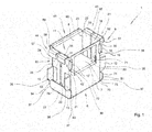
Figure 1 is a perspective view of an inner box of a package for containers of pourable food products according to the invention; -
Figure 2 is a blank of packaging material, which can be folded to obtain the inner box ofFigure 1 . - With reference to
Figure 1 there is shown aninner box 1 for a package for housing and transporting a group of containers (not shown) of pourable food products. - The
inner box 1 is intended to be received in an outer box (not shown) of the package. - The containers are preferably sealed aseptically, contain a pourable food product, such as pasteurized or UHT milk, fruit juice, wine, etc., and are made of laminated strip packaging material, as described in detail above.
- The
inner box 1 may be made from a folded blank, or unit, made of cardboard or cardboard-based material, as better explained herebelow. - The
inner box 1 comprises a bottom wall 6, and four side walls. - In particular, the inner box comprises a
first side wall 7, a second side wall 8, athird side wall 9 and afourth side wall 10. - The
first side wall 7 and the second side wall 8 face each other. - The
third side wall 9 and thefourth side wall 10 face each other. - The
first side wall 7, the second side wall 8, thethird side wall 9 and thefourth side wall 10 delimit aseat 11 arranged to house the containers. - The
inner box 1 comprises a firstside wall portion 18 extending from afirst edge portion 19 of thefirst side wall 7 and a secondside wall portion 20 extending from asecond edge portion 21, opposite to thefirst edge portion 19, of thefirst side wall 7. - The
inner box 1 further comprises a thirdside wall portion 22 extending from athird edge portion 23 of the second side wall 8 and a fourthside wall portion 24 extending from afourth edge portion 25, opposite to thethird edge portion 23, of the second side wall 8. - The
inner box 1 further comprises afirst side flap 74 extending from afirst border 75 of the bottom wall 6 and asecond side flap 76 extending from asecond border 77, opposite to thefirst border 75, of the bottom wall 6. - The first
side wall portion 18 and the thirdside wall portion 22 form thethird side wall 9. - The second
side wall portion 20 and the fourthside wall portion 24 form thefourth side wall 10. - The
first side wall 7 comprises afirst projecting element 12 projecting from thefirst edge portion 19 and asecond projecting element 13 projecting from thesecond edge portion 21. - The second side wall 8 comprises a third projecting element (not shown) projecting from the
third edge portion 23 and afourth projecting element 15 projecting from thefourth edge portion 25. - The
first projecting element 12, thesecond projecting element 13, the third projecting element and the fourth projectingelement 15 define four spacers that, when theinner box 1 is arranged inside the outer box, interact with the walls of the outer box, so that theinner box 1 may be correctly positioned with respect to the outer box. - The
first projecting element 12 and the third projecting element engage thefirst side flap 74 so as to keep theinner box 1 in an assembled configuration, i.e. a working configuration in which theinner box 1 receives the group of packages. - The
second projecting element 13 and thefourth projecting element 15 engage thesecond side flap 76 so as to keep theinner box 1 in the above-mentioned assembled configuration. - The
first projecting element 12, thesecond projecting element 13, the third projecting element and thefourth projecting element 15 comprisebeveled edges 35 converging towards the bottom wall 6 and acting as insertion promoting means that promote easy introduction of theinner box 1 into the outer box. - The first
side wall portion 18 comprises a first projectingmember 16 projecting from anedge border 30 of the firstside wall portion 18 that is connected to thefirst side wall 7. - The second
side wall portion 20 comprises a second projectingmember 17 projecting from afurther edge border 31 of the secondside wall portion 20 that is connected to thefirst side wall 7. - The
first projecting element 16 and the second projecting element also act as spacers that allow theinner box 1 to be arranged, and kept, in the desired position with respect to the outer box. - The first projecting
member 16 and the second projectingmember 17 comprisebeveled edge portions 36 converging towards the bottom wall 6 and acting as insertion promoting means that promote easy introduction of theinner box 1 into the outer box. - The
first side flap 74 comprises afirst protruding portion 81 and a second protruding portion (not shown) projecting from opposite sides of thefirst side flap 74. - When the inner box is in the working configuration, i.e. ready to receive the packages and/or already filled with the packages, the
first protruding portion 81 extends beyond thefirst side wall 7 and the second protruding portion extends beyond the second side wall 8. - The
first protruding portion 81 and the second protruding portion, therefore, act as spacers that allow a proper positioning of theinner box 1 in the outer box. - The
second side flap 76 comprises a further first protrudingportion 83 and a further second protrudingportion 84 projecting from opposite sides of thesecond side flap 76. - When the inner box is in the working configuration, i.e. ready to receive the packages and/or already filled with the packages, the further
first protruding portion 83 extends beyond thefirst side wall 7 and the furthersecond protruding portion 84 extends beyond the second side wall 8. - The further first protruding
portion 83 and the further second protrudingportion 84, therefore, act as spacers that allow a proper positioning of theinner box 1 in the outer box. - The
first protruding portion 81, the second protruding portion, the further first protrudingportion 83 and the further second protrudingportion 84 comprisebeveled edge members 37 converging towards the bottom wall 6 and acting as insertion promoting means that promote easy introduction of theinner box 1 into the outer box. - The
inner box 1 also comprises a plurality of additional spacers, in particular afirst spacer element 41 extending from the firstside wall portion 18, asecond spacer element 42 extending from the secondside wall portion 20, athird spacer element 43 extending from the thirdside wall portion 22, afourth spacer element 44 extending from the fourthside wall portion 24 and afifth spacer element 45 extending from the second side wall 8. - The
first spacer element 41 comprise afirst end flap 51 intended to interact with a wall of the outer box and a firstintermediate flap 52 connecting thefirst end flap 51 with the firstside wall portion 18. When theinner box 1 is in the above-mentioned assembled configuration, thefirst end flap 51 is substantially parallel to the firstside wall portion 18 and defines a substantially vertical plane and the firstintermediate flap 52 is substantially perpendicular to thefirst end flap 51 and to the firstside wall portion 18 and defines a substantially horizontal plane. - The
second spacer element 42 comprise asecond end flap 53 intended to interact with a wall of the outer box and a secondintermediate flap 54 connecting thesecond end flap 53 with the secondside wall portion 20. When theinner box 1 is in the above-mentioned assembled configuration, thesecond end flap 53 is substantially parallel to the secondside wall portion 20 and defines a substantially vertical plane and the secondintermediate flap 54 is substantially perpendicular to thesecond end flap 53 and to the secondside wall portion 20 and defines a substantially horizontal plane. - The
third spacer element 43 comprise athird end flap 55 intended to interact with a wall of the outer box and a thirdintermediate flap 56 connecting thethird end flap 55 with the thirdside wall portion 22. When theinner box 1 is in the above-mentioned assembled configuration, thethird end flap 55 is substantially parallel to the thirdside wall portion 22 and defines a substantially vertical plane and the thirdintermediate flap 56 is substantially perpendicular to thethird end flap 55 and to the thirdside wall portion 22 and defines a substantially horizontal plane. - The
fourth spacer element 44 comprise afourth end flap 57 intended to interact with a wall of the outer box and a fourthintermediate flap 58 connecting thefourth end flap 57 with the fourthside wall portion 24. When theinner box 1 is in the above-mentioned assembled configuration, thefourth end flap 57 is substantially parallel to the fourthside wall portion 24 and defines a substantially vertical plane and the fourthintermediate flap 58 is substantially perpendicular to thefourth end flap 57 and to the fourthside wall portion 24 and defines a substantially horizontal plane. - The
fifth spacer element 45 comprise afifth end flap 59 intended to interact with a wall of the outer box and a fifthintermediate flap 60 connecting thefifth end flap 59 with the second side wall 8. When theinner box 1 is in the above-mentioned assembled configuration, thefifth end flap 59 is substantially parallel to the second side wall 8 and defines a substantially vertical plane and the fifthintermediate flap 60 is substantially perpendicular to thefifth end flap 59 and to the second side wall 8 and defines a substantially horizontal plane. - The
first side wall 7 comprises apanel 70 that can be folded inside theseat 11 so as to define an interlayer that, in use, is interposed between a first layer of packages and a second layer of packages. - The
panel 70 is obtained by making a C-shaped throughincision 71 in thefirst side wall 7 and leaving anuncut portion 72 which acts as a hinge for thepanel 70. - When the
panel 70 is arranged inside theseat 11, the C-shape throughincision 71 and theuncut portion 72 define in the first side wall a 7 anaperture 80 though which a user can see the packages received in theinner box 1. - Owing to the
panel 70, the risk of damaging the packages is highly reduced, since thepanel 70 protects the packages. - In addition, the
panel 70 allows to have superimposed layers also in case of packages having an opening device projecting from a top wall thereof. Thepanel 70, in fact, creates a flat supporting plane for the packages of the top layer above the packages of the bottom layers, in particular above the opening devices of the packages of the bottom layer. - Owing to the first projecting
element 12, to the second projectingelement 13, to the third projectingelement 15, to the first projectingmember 16, to the second projectingmember 17, to the first protrudingportion 81, to the second protruding portion, to the third protrudingportion 83 , to the fourth protrudingportion 84 and owing especially to thefirst spacer element 41, to thesecond spacer element 42, to thethird spacer element 43, to thefourth spacer element 44 and to thefifth spacer element 45 the inner box 1 - once placed inside the outer box - can be easily maintained in the right position with respect to the outer box. - Owing to the
beveled edges 35, to thebeveled edge portions 36 and to thebeveled edge members 37 theinner box 1 can be smoothly inserted into the outer box. -
Figure 2 shows a blank 140 of cardboard or cardboard-based material, which can be folded to obtain theinner box 1. - The blank 140 comprises a
base panel element 141 arranged to form the bottom wall 6 of the inner box. - The blank 140 further comprises a first
side panel element 142 adjacent to thebase panel element 141 and arranged to form thefirst side wall 7 of theinner box 1. - A
crease line 143 extends between thebase panel element 141 and the firstside panel element 142. - The blank 140 further comprises a second
side panel element 144 adjacent to thebase panel element 141 and arranged to form the second side wall 8 of theinner box 1. - A
crease line 145 extends between thebase panel element 141 and the secondside panel element 144. - The blank 140 further comprises a first side
portion panel element 150 extending from afirst edge portion 151 of the firstside panel element 142 adjacent to thecrease line 143 and arranged to form the firstside wall portion 18 of theinner box 1. - A
crease line 152 is interposed between the first sidepanel portion element 150 and the firstside panel element 142. - The blank 140 further comprises a second side
portion panel element 153 extending from asecond edge portion 154, opposite to thefirst edge portion 151, of the firstside panel element 142 adjacent to thecrease line 143 and arranged to form the secondside wall portion 20 of theinner box 1. - A
crease line 155 is interposed between the second sidepanel portion element 153 and the firstside panel element 142. - The blank 140 further comprises a third side
portion panel element 156 extending from a furtherfirst edge portion 157 of the secondside panel element 144 adjacent to thecrease line 145 and arranged to form the thirdside wall portion 22 of theinner box 1. - A
crease line 158 is interposed between the third sidepanel portion element 156 and the secondside panel element 144. - The blank 140 further comprises a fourth side
portion panel element 159 extending from a furthersecond edge portion 160, opposite to the furtherfirst edge portion 157, of the secondside panel element 144 adjacent to thecrease line 145 and arranged to form the fourthside wall portion 24 of theinner box 1. - A
crease line 161 is interposed between the fourth sidepanel portion element 159 and the secondside panel element 144. - The blank 140 further comprises a first side
flap panel element 162 adjacent to thebase panel element 141 and arranged to form thefirst side flap 74 of theinner box 1. - A
crease line 163 extends between thebase panel element 141 and the first sideflap panel element 162. - The blank 140 further comprises a second side
flap panel element 164 adjacent to thebase panel element 141 and arranged to form thesecond side flap 76 of theinner box 1. - A
crease line 165 extends between thebase panel element 141 and the second sideflap panel element 164. - The first
side flap panel 162 and the secondside flap panel 164 comprise beveledborder members 187 converging towards thebase panel element 141 and forming thebeveled edge members 37 of theinner box 1. - The first
side panel element 142 comprises afirst appendix 170 projecting from thefirst edge potion 151 and arranged to form the first projectingelement 12 of thefirst side wall 7 of theinner box 1. - The first side
portion panel element 150 comprises afirst recesses 171 that receives thefirst appendix 170. - The first
side panel element 142 comprises asecond appendix 172 projecting from thesecond edge potion 154 and arranged to form the second projectingelement 13 of thefirst side wall 7 of theinner box 1. - The second side
portion panel element 153 comprises asecond recesses 173 that receives thesecond appendix 172. - The second
side panel element 144 comprises athird appendix 174 projecting from the furtherfirst edge potion 157 and arranged to form the third projecting element of the second side wall 8 of theinner box 1. - The third side
portion panel element 156 comprises athird recesses 175 that receives thefirst appendix 174. - The second
side panel element 144 comprises afourth appendix 176 projecting from the furthersecond edge potion 160 and arranged to form the fourth projectingelement 15 of the second side wall 8 of theinner box 1. - The fourth side
portion panel element 157 comprises afourth recesses 177 that receives thefourth appendix 176. - The
first appendix 170, thesecond appendix 172, thethird appendix 174 and thefourth appendix 176 comprise beveledborders 185 converging towards thebase panel element 141 and forming thebeveled edges 35 of theinner box 1. - The first side
panel portion element 150 comprises afirst appendix element 178 extending towards the firstside panel element 142 and arranged to form the first projectingmember 16 of the firstside wall portion 18 of theinner box 1. - The first
side panel element 142 comprises afirst recess element 179 that receives thefirst appendix element 178. - The second side
panel portion element 153 comprises asecond appendix element 180 extending towards the firstside panel element 142 and arranged to form the second projectingmember 17 of the secondside wall portion 20 of theinner box 1. - The first
side panel element 142 comprises asecond recess element 181 that receives thesecond appendix element 180. - The first projecting
element 178 and the second projectingelement 180 comprise beveledborder portions 186 converging towards thebase panel element 141 and forming thebeveled edge portions 36 of theinner box 1. - The blank 140 comprises a first
intermediate panel body 191 extending from the first sideportion panel element 150 and arranged to form the firstintermediate flap 52. - A
crease line 193 is interposed between the firstintermediate panel body 191 and the first sideportion panel element 150. - The blank 140 further comprises a first
end panel body 192 extending from the firstintermediate panel body 191 and arranged to form thefirst end flap 51. - A
crease line 194 is interposed between the firstend panel body 192 and the firstintermediate panel body 191. - The blank 140 comprises a second
intermediate panel body 195 extending from the second sideportion panel element 153 and arranged to form the secondintermediate flap 54. - A
crease line 197 is interposed between the secondintermediate panel body 195 and the second sideportion panel element 153. - The blank 140 further comprises a second
end panel body 196 extending from the secondintermediate panel body 195 and arranged to form thesecond end flap 53. - A
crease line 198 is interposed between the secondend panel body 196 and the secondintermediate panel body 195. - The blank 140 comprises a third
intermediate panel body 199 extending from the third sideportion panel element 156 and arranged to form the thirdintermediate flap 56. - A
crease line 201 is interposed between the thirdintermediate panel body 199 and the third sideportion panel element 156. - The blank 140 further comprises a third
end panel body 200 extending from the thirdintermediate panel body 199 and arranged to form thethird end flap 55. - A
crease line 202 is interposed between the thirdend panel body 200 and the thirdintermediate panel body 199. - The blank 140 comprises a fourth
intermediate panel body 203 extending from the fourth sideportion panel element 159 and arranged to form the fourthintermediate flap 58. - A
crease line 205 is interposed between the fourthintermediate panel body 203 and the fourth sideportion panel element 159. - The blank 140 further comprises a fourth
end panel body 204 extending from the fourthintermediate panel body 203 and arranged to form thefourth end flap 57. - A
crease line 206 is interposed between the fourthend panel body 204 and the fourthintermediate panel body 203. - The blank 140 comprises a fifth
intermediate panel body 207 extending from the secondside panel element 144 and arranged to form the fifthintermediate flap 60. - A
crease line 209 is interposed between the fifthintermediate panel body 207 and the secondside panel element 144. - The blank 140 further comprises a fifth
end panel body 208 extending from the fifthintermediate panel body 207 and arranged to form thefifth end flap 59. - A
crease line 210 is interposed between the fifthend panel body 208 and the fifthintermediate panel body 207. - The first
side panel element 142 comprises a C-shaped throughcut 220 that defines the C-shaped throughcut incision 71 of thefirst side wall 7 of theinner box 1. - The first
side panel element 142 comprises acrease line 221 that define theuncut portion 72 of thefirst side wall 7 of theinner box 1. - The C-shaped though
cut 220 and thecrease line 221 delimit ablank portion 222 that forms thepanel 70 of thefirst side wall 7 of theinner box 1. - Clearly, changes may be made to package 1 according to the present invention without, however, departing from the scope as defined in the accompanying claims.
Claims (15)
- An inner box for a package for containers of pourable food, said inner box being intended to be received in an outer box of said package, said inner box comprising a bottom wall (6) and a plurality of side walls (7, 8, 9, 10) that delimit a seat (11) arranged to house said containers, one of said side walls (7) comprising a panel (70) delimited by a through incision (71) and an uncut portion (72), said panel (70) being foldable around said uncut portion (72) so as to be received in said seat (11) and form an interlayer arranged to be interposed between a first layer of said packages resting on said bottom wall and a second layer of said packages resting on said first layer.
- An inner box according to claim 1, wherein said plurality of side walls comprises a first side wall (7), a second side wall (8), a third side wall (9) and a fourth side wall (10), said first side wall (7) and said second side wall (8) facing each other and said third side wall (9) and said fourth side wall (10) facing each other.
- An inner box according to claim 2, wherein said first side wall (7) comprises a first projecting element (12) and a second projecting element (13) and said second side wall (8) comprises a third projecting element and a fourth projecting element (15), said first projecting element (12), said second projecting element (13), said third projecting element and said fourth projecting element (15) defining four spacers.
- An inner box according to claim 2, or 3, wherein said first projecting element (12), said second projecting element (13), said third projecting element and said fourth projecting element (15) comprise beveled edges (35) converging towards said bottom wall (6) and acting as insertion promoting means that promote introduction of said inner box (1) into said outer box.
- An inner box according to any one of claims 2 to 4, and further comprising a first side wall portion (18), a second side wall portion (20), a third side wall portion (22) and a fourth side wall portion (24), said first side wall portion (18) and said third side wall portion (22) forming said third side wall (9) and said second side wall portion (20) and said fourth side wall portion (24) forming said fourth side wall (10), said first side wall portion (18) comprising a first projecting member (16) and a second projecting member (17), said first projecting member (16) and said second projecting member (17) defining two spacers.
- An inner box according to claim 5, wherein said first projecting member (16) and said second projecting member (17) comprise beveled edge portions (36) converging towards said bottom wall (6) and acting as insertion promoting means that promote introduction of said inner box (1) into said outer box.
- An inner box according to any one of claims 2 to 6, and further comprising a first side flap (74) extending from a first border (75) of said bottom wall (6) and a second side flap (76) extending from a second border (77), opposite to the first border (75), of said bottom wall (6), said first side flap (74) comprising a first protruding portion (81) and a second protruding portion, said second side flap (76) comprising a further first protruding portion (83) and a further second protruding portion (84), said first protruding portion (81), said second protruding portion, said further first protruding portion (83) and said further second protruding portion (84) defining four spacers.
- An inner box according to claim 7, wherein said first protruding portion (81), said second protruding portion, said further first protruding portion (83) and said further second protruding portion (84) comprise beveled edge members (37) converging towards said bottom wall (6) and acting as insertion promoting means that promote introduction of said inner box 1 into said outer box.
- An inner box according to any one of the preceding claims and further comprising spacer elements (41, 42, 43, 44, 45), said spacers extending from said side walls (8, 9, 10), each of said spacer elements comprising an end flap (51, 53, 55, 57, 59) intended to interact with a wall of said outer box and an intermediate flap (52, 54, 56, 58, 60) connecting said end flap (51, 53, 55, 57, 59) with a corresponding side wall (7, 8, 9, 10).
- A blank of packaging material for producing an inner box (1) of a package for containers of pourable food, said inner box (1) being intended to be received in an outer box of said package, said blank comprising a base panel element (141) arranged to form a bottom wall (6) of said inner box (1), and a plurality of side panel elements (142, 144, 150, 153, 156, 159) arranged to form a plurality of side walls (7, 8, 9, 10) of said inner box (1), one of said side panel elements (142) comprising a blank portion (222) delimited by a through cut (220) and a crease line (221), said blank portion (222) being foldable around said crease line (221) so as to be received in a seat (11) of said inner box (1) intended to house said packages and form an interlayer arranged to be interposed between a first layer of said packages resting on said bottom wall (6) and a second layer of said packages resting on said first layer.
- A blank according to claim 10, wherein said plurality of side panel elements (142, 144, 150, 153, 156, 159) comprises a first side panel element (142) arranged to form a first side wall (7) of said inner box (1), a second side panel element (144) arranged to form a second side wall (8) of said inner box (1), a first side portion panel element (150), a second side portion panel element (153), a third side portion panel element (156) and a fourth side portion panel element (159), said first side portion panel element (150) and said third side portion panel element (156) forming a third side wall (9) of said inner box (1), and said second side portion panel element (153) and said fourth side portion panel element (159) forming a fourth side wall (10) of said inner box (1).
- A blank according to claim 11, wherein said first side panel element (142) comprises a first appendix (170) and said first side portion panel element (150) comprises a first recesses (171) that receives said first appendix (170), said first side panel element (142) comprises a second appendix (172) and said second side portion panel element (153) comprises a second recesses (173) that receives said second appendix (172), said second side panel element (144) comprises a third appendix (174) and said third side portion panel element (156) comprises a third recesses (175) that receives said first appendix (174), said second side panel element (144) comprises a fourth appendix (176) and said fourth side portion panel element (157) comprises a fourth recesses (177) that receives the fourth appendix (176), said first appendix (170), said second appendix (172), said third appendix (174) and said fourth appendix (176) comprising beveled borders (185) converging towards said base panel element (141) and forming beveled edges (35) of said inner box (1).
- A blank according to any one of claim 11 to 13, wherein said first side panel portion element (150) comprises a first appendix element (178) and said first side panel element (142) comprises a first recess element (179) that receives said first appendix element (178), and said second side panel portion element (153) comprises a second appendix element (180) and said first side panel element (142) comprises a second recess element (181) that receives said second appendix element (180), said first projecting element (178) and said second projecting element (180) comprising beveled border portions (186) converging towards said base panel element (141) and forming beveled edge portions (36) said the inner box (1).
- A blank according to any one of claims 11 to 14, and further comprising a first side flap panel element (162) adjacent to said base panel element (141) and arranged to form a first side flap (74) of said inner box (1) and a second side flap panel element (164) adjacent to said base panel element (141) and arranged to form a second side flap (76) of said inner box (1), said first side flap panel (162) and said second side flap panel (164) comprising beveled border members (187) converging towards said base panel element (141) and forming beveled edge members (37) of said inner box (1).
- A blank according to any one of claims 10 to 14, and further comprising a plurality of intermediate panel bodies (191, 195, 199, 203, 207) and a plurality of end panel bodies (192, 196, 200, 204, 208), each intermediate panel body (191, 195, 199, 203, 207) cooperating with a corresponding end panel body (192, 196, 200, 204, 208) to form a spacer element (41, 42, 43, 44, 45) of said inner box (1), each of said intermediate panel body (191, 195, 199, 203, 207) extending from a respective side panel element (144, 150, 153, 156, 159) and each end panel body (192, 196, 200, 204, 208) extending from a respective intermediate panel body (191, 195, 199, 203, 207).
Priority Applications (2)
| Application Number | Priority Date | Filing Date | Title |
|---|---|---|---|
| EP15184364.6A EP3141490A1 (en) | 2015-09-09 | 2015-09-09 | Package for containers of pourable food products |
| CN201610567528.6A CN106516329A (en) | 2015-09-09 | 2016-07-19 | Package for containers of pourable food products |
Applications Claiming Priority (1)
| Application Number | Priority Date | Filing Date | Title |
|---|---|---|---|
| EP15184364.6A EP3141490A1 (en) | 2015-09-09 | 2015-09-09 | Package for containers of pourable food products |
Publications (1)
| Publication Number | Publication Date |
|---|---|
| EP3141490A1 true EP3141490A1 (en) | 2017-03-15 |
Family
ID=54072720
Family Applications (1)
| Application Number | Title | Priority Date | Filing Date |
|---|---|---|---|
| EP15184364.6A Withdrawn EP3141490A1 (en) | 2015-09-09 | 2015-09-09 | Package for containers of pourable food products |
Country Status (2)
| Country | Link |
|---|---|
| EP (1) | EP3141490A1 (en) |
| CN (1) | CN106516329A (en) |
Citations (7)
| Publication number | Priority date | Publication date | Assignee | Title |
|---|---|---|---|---|
| US2321473A (en) * | 1940-12-26 | 1943-06-08 | Inland Container Corp | Carton structure |
| US2513902A (en) * | 1948-11-30 | 1950-07-04 | Robertson Paper Box Co | Carton |
| FR1347104A (en) * | 1962-11-06 | 1963-12-27 | Procedes Modernes D Impression | Improvements to packaging, in particular for computer files and the like |
| FR2354250A1 (en) * | 1976-06-09 | 1978-01-06 | Habert Robert | Presentation packing box with inserts - has inner lining fitting inside box and giving thickness to walls |
| US4925087A (en) * | 1989-09-06 | 1990-05-15 | R. G. Barry Corporation | Packaging container with display window |
| EP1502862A1 (en) * | 2003-08-01 | 2005-02-02 | Johnson & Johnson Consumer France | Packaging for cosmetic, human therapeutic or human hygiene product receptacle with improved gussets configuration |
| AU2010212328A1 (en) * | 2002-06-07 | 2010-09-09 | Cospak Pty Ltd | A carton divider system |
Family Cites Families (7)
| Publication number | Priority date | Publication date | Assignee | Title |
|---|---|---|---|---|
| US3534691A (en) * | 1968-06-17 | 1970-10-20 | Joseph Carlomagno Jr | Three-dimensional carton-spacer |
| US4219148A (en) * | 1979-03-28 | 1980-08-26 | Champion International Corporation | Unitary paperboard divider device for a carton |
| FR2945525B1 (en) * | 2009-05-14 | 2015-05-29 | Roquette Freres | FLEXIBLE CONTAINER FOR THE PACKAGING OF PARTICULATE SOLID PARTICLES IN BULK. |
| CN203255422U (en) * | 2013-05-08 | 2013-10-30 | 中山中荣纸类印刷制品有限公司 | Anti-collision packing box |
| CN204137579U (en) * | 2014-10-17 | 2015-02-04 | 豪门印刷(上海)有限公司 | A kind of shockproof plastic packing box |
| CN204280148U (en) * | 2014-12-05 | 2015-04-22 | 金箭印刷事业有限公司 | The inner disk structure of the box |
| CN204473411U (en) * | 2015-02-06 | 2015-07-15 | 保定天达纸品有限公司 | Single piece type folding forming package lining |
-
2015
- 2015-09-09 EP EP15184364.6A patent/EP3141490A1/en not_active Withdrawn
-
2016
- 2016-07-19 CN CN201610567528.6A patent/CN106516329A/en active Pending
Patent Citations (7)
| Publication number | Priority date | Publication date | Assignee | Title |
|---|---|---|---|---|
| US2321473A (en) * | 1940-12-26 | 1943-06-08 | Inland Container Corp | Carton structure |
| US2513902A (en) * | 1948-11-30 | 1950-07-04 | Robertson Paper Box Co | Carton |
| FR1347104A (en) * | 1962-11-06 | 1963-12-27 | Procedes Modernes D Impression | Improvements to packaging, in particular for computer files and the like |
| FR2354250A1 (en) * | 1976-06-09 | 1978-01-06 | Habert Robert | Presentation packing box with inserts - has inner lining fitting inside box and giving thickness to walls |
| US4925087A (en) * | 1989-09-06 | 1990-05-15 | R. G. Barry Corporation | Packaging container with display window |
| AU2010212328A1 (en) * | 2002-06-07 | 2010-09-09 | Cospak Pty Ltd | A carton divider system |
| EP1502862A1 (en) * | 2003-08-01 | 2005-02-02 | Johnson & Johnson Consumer France | Packaging for cosmetic, human therapeutic or human hygiene product receptacle with improved gussets configuration |
Also Published As
| Publication number | Publication date |
|---|---|
| CN106516329A (en) | 2017-03-22 |
Similar Documents
| Publication | Publication Date | Title |
|---|---|---|
| US11667428B2 (en) | Sheet packaging matertial for producing a sealed package containing a pourable product and a package obtained therefrom | |
| US12037167B2 (en) | Sheet packaging material for producing a sealed package containing a pourable food product and a sealed package obtained from a sheet packaging material | |
| EP3556673B1 (en) | A sealed package containing a pourable food product and a sheet packaging material for producing a sealed package containing a pourable food product | |
| EP3219633B1 (en) | A sheet packaging material | |
| US20160325872A1 (en) | Sealed package for pourable food products and a basic unit of sheet packaging material for producing sealed packages for pourable food products | |
| US10301063B2 (en) | Package material and package container formed with said material | |
| EP3020644A1 (en) | Package for containers of pourable food products | |
| WO2025190580A1 (en) | A packaging blank for producing a sealed package and package | |
| CN117083227A (en) | Composite packaging material sheet, method of forming composite packaging material sheet, composite packaging and method of forming composite packaging | |
| EP4458708A1 (en) | Packaging blank for forming a package and package formed from a packaging blank | |
| US11932461B2 (en) | Sheet packaging material for producing sealed packages for liquid food products | |
| CN106516329A (en) | Package for containers of pourable food products | |
| EP4420993A1 (en) | A multilayer sheet of packaging material for producing a sealed a package | |
| EP4741305A1 (en) | Packaging blank for forming a package, package formed from a packaging blank and package | |
| JP2025524894A (en) | Packaging blank for forming a package and package formed from the packaging blank | |
| WO2024027991A1 (en) | Packaging blank for forming a package and package formed from a packaging blank | |
| WO2026098986A1 (en) | Packaging blank for forming a package, package formed from a packaging blank and package | |
| ITTO20080055U1 (en) | PACKAGE FOR CONTAINERS OF VERSABLE FOOD PRODUCTS | |
| ITTO20080052U1 (en) | PACKAGE FOR CONTAINERS OF VERSABLE FOOD PRODUCTS |
Legal Events
| Date | Code | Title | Description |
|---|---|---|---|
| PUAI | Public reference made under article 153(3) epc to a published international application that has entered the european phase |
Free format text: ORIGINAL CODE: 0009012 |
|
| STAA | Information on the status of an ep patent application or granted ep patent |
Free format text: STATUS: THE APPLICATION HAS BEEN PUBLISHED |
|
| AK | Designated contracting states |
Kind code of ref document: A1 Designated state(s): AL AT BE BG CH CY CZ DE DK EE ES FI FR GB GR HR HU IE IS IT LI LT LU LV MC MK MT NL NO PL PT RO RS SE SI SK SM TR |
|
| AX | Request for extension of the european patent |
Extension state: BA ME |
|
| STAA | Information on the status of an ep patent application or granted ep patent |
Free format text: STATUS: THE APPLICATION IS DEEMED TO BE WITHDRAWN |
|
| 18D | Application deemed to be withdrawn |
Effective date: 20170916 |