EP3141293B1 - Diesel fuel filter assembly - Google Patents
Diesel fuel filter assembly Download PDFInfo
- Publication number
- EP3141293B1 EP3141293B1 EP16187769.1A EP16187769A EP3141293B1 EP 3141293 B1 EP3141293 B1 EP 3141293B1 EP 16187769 A EP16187769 A EP 16187769A EP 3141293 B1 EP3141293 B1 EP 3141293B1
- Authority
- EP
- European Patent Office
- Prior art keywords
- fuel
- filtered
- set forth
- filter media
- water separator
- Prior art date
- Legal status (The legal status is an assumption and is not a legal conclusion. Google has not performed a legal analysis and makes no representation as to the accuracy of the status listed.)
- Active
Links
- 239000002283 diesel fuel Substances 0.000 title claims description 48
- XLYOFNOQVPJJNP-UHFFFAOYSA-N water Substances O XLYOFNOQVPJJNP-UHFFFAOYSA-N 0.000 claims description 79
- 239000000446 fuel Substances 0.000 claims description 52
- 238000001914 filtration Methods 0.000 claims description 48
- 230000002093 peripheral effect Effects 0.000 claims description 39
- 230000004888 barrier function Effects 0.000 claims description 23
- 230000005611 electricity Effects 0.000 claims description 4
- 239000007787 solid Substances 0.000 claims description 4
- 230000003068 static effect Effects 0.000 claims description 4
- 238000013022 venting Methods 0.000 claims description 2
- 230000000712 assembly Effects 0.000 description 3
- 238000000429 assembly Methods 0.000 description 3
- 238000007789 sealing Methods 0.000 description 3
- 238000000926 separation method Methods 0.000 description 3
- 239000002828 fuel tank Substances 0.000 description 2
- 230000013011 mating Effects 0.000 description 2
- 238000003466 welding Methods 0.000 description 2
- 239000000853 adhesive Substances 0.000 description 1
- 230000001070 adhesive effect Effects 0.000 description 1
- 230000000295 complement effect Effects 0.000 description 1
- 230000003247 decreasing effect Effects 0.000 description 1
- 230000001627 detrimental effect Effects 0.000 description 1
- 238000009792 diffusion process Methods 0.000 description 1
- 230000007613 environmental effect Effects 0.000 description 1
- 239000012530 fluid Substances 0.000 description 1
- 230000005484 gravity Effects 0.000 description 1
- 230000002209 hydrophobic effect Effects 0.000 description 1
- 238000002347 injection Methods 0.000 description 1
- 239000007924 injection Substances 0.000 description 1
- 239000000463 material Substances 0.000 description 1
- 238000000034 method Methods 0.000 description 1
- 238000012986 modification Methods 0.000 description 1
- 230000004048 modification Effects 0.000 description 1
- ORQBXQOJMQIAOY-UHFFFAOYSA-N nobelium Chemical compound [No] ORQBXQOJMQIAOY-UHFFFAOYSA-N 0.000 description 1
- 238000004806 packaging method and process Methods 0.000 description 1
Images


Classifications
-
- B—PERFORMING OPERATIONS; TRANSPORTING
- B01—PHYSICAL OR CHEMICAL PROCESSES OR APPARATUS IN GENERAL
- B01D—SEPARATION
- B01D35/00—Filtering devices having features not specifically covered by groups B01D24/00 - B01D33/00, or for applications not specifically covered by groups B01D24/00 - B01D33/00; Auxiliary devices for filtration; Filter housing constructions
- B01D35/30—Filter housing constructions
-
- B—PERFORMING OPERATIONS; TRANSPORTING
- B01—PHYSICAL OR CHEMICAL PROCESSES OR APPARATUS IN GENERAL
- B01D—SEPARATION
- B01D17/00—Separation of liquids, not provided for elsewhere, e.g. by thermal diffusion
- B01D17/02—Separation of non-miscible liquids
- B01D17/04—Breaking emulsions
- B01D17/045—Breaking emulsions with coalescers
-
- B—PERFORMING OPERATIONS; TRANSPORTING
- B01—PHYSICAL OR CHEMICAL PROCESSES OR APPARATUS IN GENERAL
- B01D—SEPARATION
- B01D29/00—Filters with filtering elements stationary during filtration, e.g. pressure or suction filters, not covered by groups B01D24/00 - B01D27/00; Filtering elements therefor
- B01D29/01—Filters with filtering elements stationary during filtration, e.g. pressure or suction filters, not covered by groups B01D24/00 - B01D27/00; Filtering elements therefor with flat filtering elements
- B01D29/05—Filters with filtering elements stationary during filtration, e.g. pressure or suction filters, not covered by groups B01D24/00 - B01D27/00; Filtering elements therefor with flat filtering elements supported
- B01D29/07—Filters with filtering elements stationary during filtration, e.g. pressure or suction filters, not covered by groups B01D24/00 - B01D27/00; Filtering elements therefor with flat filtering elements supported with corrugated, folded or wound filtering sheets
-
- B—PERFORMING OPERATIONS; TRANSPORTING
- B01—PHYSICAL OR CHEMICAL PROCESSES OR APPARATUS IN GENERAL
- B01D—SEPARATION
- B01D35/00—Filtering devices having features not specifically covered by groups B01D24/00 - B01D33/00, or for applications not specifically covered by groups B01D24/00 - B01D33/00; Auxiliary devices for filtration; Filter housing constructions
- B01D35/005—Filters specially adapted for use in internal-combustion engine lubrication or fuel systems
-
- B—PERFORMING OPERATIONS; TRANSPORTING
- B01—PHYSICAL OR CHEMICAL PROCESSES OR APPARATUS IN GENERAL
- B01D—SEPARATION
- B01D36/00—Filter circuits or combinations of filters with other separating devices
- B01D36/001—Filters in combination with devices for the removal of gas, air purge systems
-
- B—PERFORMING OPERATIONS; TRANSPORTING
- B01—PHYSICAL OR CHEMICAL PROCESSES OR APPARATUS IN GENERAL
- B01D—SEPARATION
- B01D36/00—Filter circuits or combinations of filters with other separating devices
- B01D36/003—Filters in combination with devices for the removal of liquids
-
- B—PERFORMING OPERATIONS; TRANSPORTING
- B01—PHYSICAL OR CHEMICAL PROCESSES OR APPARATUS IN GENERAL
- B01D—SEPARATION
- B01D36/00—Filter circuits or combinations of filters with other separating devices
- B01D36/003—Filters in combination with devices for the removal of liquids
- B01D36/008—Means to filter or treat the separated liquid
-
- F—MECHANICAL ENGINEERING; LIGHTING; HEATING; WEAPONS; BLASTING
- F02—COMBUSTION ENGINES; HOT-GAS OR COMBUSTION-PRODUCT ENGINE PLANTS
- F02M—SUPPLYING COMBUSTION ENGINES IN GENERAL WITH COMBUSTIBLE MIXTURES OR CONSTITUENTS THEREOF
- F02M37/00—Apparatus or systems for feeding liquid fuel from storage containers to carburettors or fuel-injection apparatus; Arrangements for purifying liquid fuel specially adapted for, or arranged on, internal-combustion engines
- F02M37/22—Arrangements for purifying liquid fuel specially adapted for, or arranged on, internal-combustion engines, e.g. arrangements in the feeding system
- F02M37/24—Arrangements for purifying liquid fuel specially adapted for, or arranged on, internal-combustion engines, e.g. arrangements in the feeding system characterised by water separating means
- F02M37/26—Arrangements for purifying liquid fuel specially adapted for, or arranged on, internal-combustion engines, e.g. arrangements in the feeding system characterised by water separating means with water detection means
-
- F—MECHANICAL ENGINEERING; LIGHTING; HEATING; WEAPONS; BLASTING
- F02—COMBUSTION ENGINES; HOT-GAS OR COMBUSTION-PRODUCT ENGINE PLANTS
- F02M—SUPPLYING COMBUSTION ENGINES IN GENERAL WITH COMBUSTIBLE MIXTURES OR CONSTITUENTS THEREOF
- F02M37/00—Apparatus or systems for feeding liquid fuel from storage containers to carburettors or fuel-injection apparatus; Arrangements for purifying liquid fuel specially adapted for, or arranged on, internal-combustion engines
- F02M37/22—Arrangements for purifying liquid fuel specially adapted for, or arranged on, internal-combustion engines, e.g. arrangements in the feeding system
- F02M37/32—Arrangements for purifying liquid fuel specially adapted for, or arranged on, internal-combustion engines, e.g. arrangements in the feeding system characterised by filters or filter arrangements
-
- F—MECHANICAL ENGINEERING; LIGHTING; HEATING; WEAPONS; BLASTING
- F02—COMBUSTION ENGINES; HOT-GAS OR COMBUSTION-PRODUCT ENGINE PLANTS
- F02M—SUPPLYING COMBUSTION ENGINES IN GENERAL WITH COMBUSTIBLE MIXTURES OR CONSTITUENTS THEREOF
- F02M37/00—Apparatus or systems for feeding liquid fuel from storage containers to carburettors or fuel-injection apparatus; Arrangements for purifying liquid fuel specially adapted for, or arranged on, internal-combustion engines
- F02M37/22—Arrangements for purifying liquid fuel specially adapted for, or arranged on, internal-combustion engines, e.g. arrangements in the feeding system
- F02M37/54—Arrangements for purifying liquid fuel specially adapted for, or arranged on, internal-combustion engines, e.g. arrangements in the feeding system characterised by air purging means
-
- B—PERFORMING OPERATIONS; TRANSPORTING
- B01—PHYSICAL OR CHEMICAL PROCESSES OR APPARATUS IN GENERAL
- B01D—SEPARATION
- B01D2201/00—Details relating to filtering apparatus
- B01D2201/50—Means for dissipating electrostatic charges
-
- B—PERFORMING OPERATIONS; TRANSPORTING
- B01—PHYSICAL OR CHEMICAL PROCESSES OR APPARATUS IN GENERAL
- B01D—SEPARATION
- B01D2201/00—Details relating to filtering apparatus
- B01D2201/60—Shape of non-cylindrical filtering elements
-
- B—PERFORMING OPERATIONS; TRANSPORTING
- B01—PHYSICAL OR CHEMICAL PROCESSES OR APPARATUS IN GENERAL
- B01D—SEPARATION
- B01D2201/00—Details relating to filtering apparatus
- B01D2201/60—Shape of non-cylindrical filtering elements
- B01D2201/605—Square or rectangular
Definitions
- the invention of the present application relates generally toward a filtration assembly for a diesel fuel system. More specifically, the invention of the present application relates toward an optimized configuration of a filter assembly for a diesel fuel system.
- Diesel fuel engines have become increasingly complex to meet both mileage requirements and environmental standards. As such, diesel fuel being delivered to these highly technical engines is required to be both particulate-free, and substantially absent of water and air, all of which can reduce diesel fuel engine performance and durability.
- diesel fuel is filtered using a cylindrical filter making use of a concentric filtration arrangement.
- a particulate filter that separates particulates from the diesel fuel is disposed within a tubular housing.
- a water separator when included, is typically aligned in the central portion of the tubular housing in a concentric orientation relative to the filtration media. The water separator reduces the amount of water disposed in the diesel fuel prior to delivering diesel fuel to the diesel engine.
- diesel fuel passes through the particulate filter media and subsequently through the water filtration system formed from one or more concentric layers before exiting the cylindrical filter.
- the filtration and filter element assembly of the present invention is disclosed in the subject-matter of claims 1-16.
- the filtration assembly for filtering diesel fuel used by a diesel engine is disposed within the housing defining an unfiltered fuel inlet and a filtered fuel outlet.
- a filter element is disposed within the housing and receives fuel from the housing fuel inlet.
- the filter element defines a peripheral wall including a filter media sealably engaged within an inner surface of the peripheral wall.
- the filter media separates an unfiltered side from a filtered side of the filter element.
- the unfiltered side is enclosed with an impermeable barrier that is sealably affixed to the peripheral wall.
- the filtered side is covered with a permeable water diffuser allowing filtered fuel to pass through to an enclosure defined by the housing.
- a water separator assembly is disposed externally to the filter element and receives filtered fuel via the water diffuser.
- the water separator assembly includes water separator media for preventing water from passing into the separator.
- the separator assembly is interconnected to the filtered fuel outlet for providing filtered, dewatered diesel fuel to the diesel engine.
- the assembly of the present invention solves a number of problems known to the prior art can-shaped diesel fuel filters.
- the filter element, and therefore the housing shape have a cuboid configuration providing a relatively flat filtration assembly.
- the flat filtration assembly is more easily packaged within architectural constraints of a modern diesel engine vehicle. Architectural constraints are defined by the engine, the engine compartment, the vehicle frame and the diesel fuel tank compartment.
- distancing the water separator from the filtration media and water diffuser provides a more functional and therefore enhanced water separation.
- diesel fuel having a low moisture content required of modern highly technical diesel engines can now be provided.
- additional filtration surface area is also achieved.
- the filtration media disposed within the filter element of the present invention extends in a linear manner providing the ability to include more filter media within the filter element than is possible of a can-shaped filter assembly where the filtration media must be compressed to a cylindrical configuration.
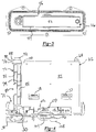
- a filtration assembly for filtering diesel fuel used by a diesel engine is generally shown at 10.
- the assembly 10 includes a housing 12 defined by an upper housing portion 14 and a lower housing portion 16.
- the upper housing portion 14 is releaseably secured to the lower housing portion 16 by a plurality of fasteners 18 used to seal the upper housing portion 14 to the lower housing portion 16.
- the fasteners 18 are contemplated to be threaded studs that are received by nuts (not shown) that are integrally molded with the upper housing portion 14.
- alternative fastening techniques, including spring clips capable of providing sufficient sealing force between the upper housing portion 14 and the lower housing portion 16 are within the scope of this invention. In this manner, diesel fuel is prevented from leaking through a mating joint 20 defined between the upper housing portion 14 and the lower housing portion 16.
- the housing 12 includes an upper housing portion 14 and a lower housing portion 16.
- the housing 12 can take the form of a nonserviceable assembly 10 formed from a single housing element or two mating elements that are permanently affixed as will be explained further herein below.
- a manifold 21 receives and evacuates diesel fuel from the housing 12.
- An unfiltered fuel inlet 22 is interconnected to the manifold 21 for delivering unfiltered fuel to the housing 12.
- a filtered fuel outlet 24 evacuates filtered fuel from the housing 12 and is interconnected with the diesel engine in a known manner.
- a manifold includes a recirculation inlet 23 and a recirculation outlet 25 that respectively receives and returns fuel to the fuel tank.
- the upper housing portion 14 and the lower housing portion 16 define a plurality of ribs that are configured to provide structural integrity to the housing 12.
- the ribs 17 present a web-like pattern that prevents the housing 12 from collapsing when a fuel pump (not shown) creates a negative pressure inside the housing 12 to extract diesel fuel from the diesel fuel tank.
- a fuel pump not shown
- the fuel pump could also be located to push fuel into the housing 12 creating a positive pressure inside the assembly 10.
- a water outlet 30 is disposed in a bottom wall 32 of the lower housing portion 16.
- the water outlet 30 is configured as a slot at the base of an outlet member 31 extending upwardly from the bottom wall 32 into the lower housing portion 16.
- the outlet member extends downwardly or the outlet is defined by an aperture in the bottom wall 32.
- a valve cap 34 sealably engages a water outlet 30 for selective release of water filtered from the diesel fuel as will be explained further herein below.
- the valve cap 34 provides for draining fuel and water contained in the assembly 10 during service when disconnected or released from the water outlet 30.
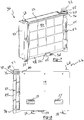
- a filter element 36 is disposed within the housing 12 and is fully concealed on the upper housing portion 14 and the lower housing portion 16 is each sealably engaged.
- the filter element 36 is interconnected with cooperable links 38 to the lower housing portion 16 when engaged with connectors 40 that extend upwardly from the lower housing portion 16. Full engagement between the links 38 and the connectors 40 properly locates the filter element 36 within the housing 12.
- the filter element 36 defines a peripheral wall 42 having a cuboid or boxlike shape.
- An impermeable barrier 44 is sealably affixed to the peripheral wall 42 over first opening.
- the links extend from a lower member of the peripheral wall 42.
- a permeable water diffuser or barrier 46 is supported by a grid-shaped support feature 48.
- the grid-shaped support feature 48 is sealably affixed to the peripheral wall 42 over a second opening on an opposite side of the peripheral wall 42 from the first opening so that fluid exits the filter element 36 through the permeable barrier 44. While the intent is that all of the fuel exits the filter element 36 through the water diffuser 46, it is possible that some of the fuel leaks through the abutment between the peripheral wall 42 and the support feature 48. Therefore, as used herein, sealably affixed means a substantially sealed abutment or a partially sealed abutment.
- the support feature 48 and the impermeable barrier 44 are sealably affixed over opposing sides of the peripheral wall 42 by way of sonic welding, laser welding, adhesive, or the like so that a fluidly sealable joint is formed between the peripheral wall 42, the permeable barrier 44 and the support feature 48. Therefore, diesel fuel entering the filter element 36 may only exit the fuel element 36 though the permeable barrier 46.
- the permeable barrier 46 takes the form of a water diffuser capable of diffusing droplets of water disposed in diesel fuel flowing through the filter assembly 10.
- the water diffuser 46 is contemplated to take form of a coalescent felt or mesh.
- the water diffuser 46 includes a second hydrophobic mesh to that described below.
- the support feature 48 receives a conductive member 50 through a slot 52 as is best represented in Figure 7 .
- the conductive member 50 defines a plurality of fingers 54 as best shown in Figure 9 .
- the fingers 54 are inserted through the slot 52 to contact filter media 56 disposed inside the filter element 36.
- the filter media 56 is best represented in Figures 5 and 6 and will be explained further herein below.
- the filter media 56 is formed from an elongated filter paper including a plurality of fold 58 as best represented in Figure 6 . Therefore, the filter media 56 takes the form of a corrugated media sheet providing an increased surface area of filtration to the filter element 36 over an un-corrugated media sheet.
- the filter media 56 defines a peripheral edge 60, the full extent of which is sealed within the peripheral wall 42 of the filter element 36.
- the filter media 56 is inserted into an injection die cavity (not shown) and polymeric material defining the peripheral wall 42 is injected into the die cavity sealing the peripheral edge 60 of the filter media 56 within the resultant peripheral wall 42.
- the filter media 56 now separates an unfiltered side 62 from a filtered side 64 of the filter element 36.
- the unfiltered side 62 forms an unfiltered chamber 66 with the impermeable barrier 44. Therefore, fuel received through filter element inlet 68 into the unfiltered chamber 66 may only be evacuated through the filter media 56.
- the filtered side 64 of the filter media 56 forms a filtered chamber 70 with the permeable barrier 46. Therefore, fuel passing through the filter media 56 from the unfiltered side 62 fills the filter chamber 70 and is evacuated from the filter chamber 70 through the permeable barrier 46. It should be understood by those of ordinary skill in the art that filtered fuel fills the housing 12 of the filtration assembly 10 after having passed through both the filter media 56 and the permeable barrier 46. As such, filtered diesel fuel fills a space 71 disposed between the filter element 36 and the housing 12.
- the water separator assembly 72 is secured to a side member 74 of the peripheral wall 42 and is disposed in a substantially vertical orientation.
- the water separator assembly 72 is received by an upper mount 76 and a lower mount 78 each of which extend outwardly from the side member 74 of the peripheral wall 42. It has been determined that spacing the water separation assembly 72 from the filter media 56 and permeable barrier 46 defining a water diffuser enhances the ability to separate water from the diesel fuel.
- the water separator assembly 72 includes a tubular frame 80 defining a support lattice 82.
- a water separator 84 takes the form of a screen extending between openings of a support lattice 82.
- the water separator 84 allows filtered fuel to pass into the tubular frame 80 while preventing water from entering the tubular frame 80. Because water has a higher specific gravity than a diesel fuel, water collecting upon the water separator 84 falls to the water outlet 30 defined in the bottom wall 32 of the lower housing portion 16 where it is drained upon releasing the valve cap 34. It should also be understood that the entire assembly 10 may also be drained of diesel fuel by releasing the valve cap 34.
- a tube 86 extends downwardly into the tubular frame 80.
- the tube 86 includes a sealed portion 88 that seals to an upper flange 90 of the tubular frame 80.
- a sealing grommet 92 receives the sealed portion 88 of the tube 86.
- the grommet 92 seals to the filtered fuel outlet 24 in a manner that prevents diesel fuel containing water being evacuated from the filtration assembly 10 through the filtered fuel outlet 24. Therefore, to exit the filter assembly 10 through the filtered fuel outlet 24, fuel must first pass through the water separator 84 and enter a lower end 94 of the tube 86. The fuel then flows upwardly in the tube 86 and exits the filter assembly through the clean fuel outlet 24.
- the filter assembly 10 is also configured to reduce, and even recirculate air trapped in the diesel fuel from entering the diesel engine through the filter assembly 10.
- the tube 86 includes an upper air aperture 96 and a lower air aperture 98.
- the upper air aperture 96 includes a similar cross-sectional area as does the lower air aperture 98 to balance evacuation of air from the tube 86. Therefore, air entering the tube 86 is trapped between the upper air aperture 96 and the lower air aperture 98.
- the impermeable barrier 44 affixed to the peripheral wall 42 and the filter element 36 includes an air vent 100 located in an upper corner 102 to allow air to vent from the filter element 36. Therefore, while the impermeable barrier has been described herein above as being sealably affixed to the peripheral wall 42, it is possible that some diesel fuel will escape through the air vent 100.
- the conductive element 50 abuts a ground element 102 of a sensor 104.
- the sensor 104 is received through an opening 106 defined by the lower housing portion 16.
- the sensor 104 includes an electrical connector 108 that includes the ground 102 and a connection to a vehicle controller (not shown).
- the sensor 104 senses the amount of moisture disposed within the diesel fuel contained inside the housing 12 along with providing a ground 102 to eliminate static electricity derived from the fuel passing through the filter media 56.
- a filtration assembly for filtering diesel fuel used by a diesel engine, comprising a housing defining an unfiltered fuel inlet and a filtered fuel outlet; a filter element disposed within said housing and receiving fuel from said housing fuel inlet; said filter element defining a peripheral wall including filter media sealably engaged therewith defining an unfiltered side and a filtered side of said filter element, said unfiltered side being enclosed with an impermeable barrier sealably affixed to said peripheral wall and said filtered side being enclosed with a permeable water diffuser allowing filtered fuel to pass therethough; a water separator assembly disposed externally to said filter element and receiving filtered fuel via said water diffuser, said water separator assembly including water separator media for preventing water from passing into said separator; and wherein said separator assembly being interconnected to said filtered fuel outlet for providing filtered, dewatered diesel fuel to the diesel engine.
- said water separator assembly may be interconnected to said peripheral wall of said filter element inside said housing.
- said water separator may include an air modulator for modulating an amount of air passing though said water separator to said filtered fuel outlet.
- said air modulator may comprise a substantial vertical tube extending downwardly from a sealable engagement with said filtered fuel outlet with said substantially vertical tube defining upper air aperture and a lower air aperture spaced beneath said upper air aperture.
- said water separator may define a solid wall proximate said filtered fuel outlet, said solid wall circumscribing said substantially vertical tube and defining a wall aperture having a similar aperture cross-section as said upper air aperture defined by said substantially vertical tube.
- said filter media may present a continuous corrugated configuration thereby increasing surface area of filtration.
- said filter media may define an edge being integrally molded within said peripheral wall.
- said filter element may be substantially box shaped and said water separator may be substantially tubular.
- the filter element may include a conductive member interconnecting said filter media and a ground thereby dissipating static electricity generated by fuel passing though said filter element.
- said housing may define a first housing portion being sealably engaged to a second housing portion and said filter element may be releaseably secured to one of said first housing portion or said second housing portion.
- said filter element may be irretrievably secured within said housing.
- a filter element assembly for filtering diesel fuel comprising: a vessel defined by a peripheral wall having a cuboid configuration with a first face defining a first opening and an opposing second face defining a second opening, said first opening being sealed by an impermeable barrier and said second opening being covered by a permeable member; filter media disposed inside said vessel defining a continuous edge sealably affixed at said peripheral wall thereby bifurcating said vessel into a unfiltered chamber and a filtered chamber whereby fuel passes from said unfiltered chamber to said filtered chamber though said filter media; and a water separator disposed externally to said vessel for separating water from filtered diesel fuel received from said water separator.
- said permeable member may comprise a water diffuser.
- said filter media may comprise a continuous corrugated sheet of filter media.
- said permeable member may include a grid shaped support feature having a peripheral element sealably affixed to said peripheral wall of said vessel.
- said water diffuser may extend between open spaces defined by said grid.
- the assembly may further including a conductive member interconnecting said filter media and a grounded element thereby dissipating static electricity generated by fuel passing though said filter element.
- said grounded element may include a plurality of fingers being received by folds disposed in said corrugated filter media.
- said water separator may include an air modulator for modulating an amount of air passing though said water separator.
- said air modulator may comprise a substantially vertical tube defining upper air aperture and a lower air aperture spaced beneath said upper air aperture.
- said impermeable barrier may comprise an air vent being cooperable with an air modulator disposed in said water separator for venting air from said vessel.
- said continuous edge of said filter media may be embedded in said peripheral wall thereby sealably affixing said filter media to said peripheral wall.
Description
- The invention of the present application relates generally toward a filtration assembly for a diesel fuel system. More specifically, the invention of the present application relates toward an optimized configuration of a filter assembly for a diesel fuel system.
- Diesel fuel engines have become increasingly complex to meet both mileage requirements and environmental standards. As such, diesel fuel being delivered to these highly technical engines is required to be both particulate-free, and substantially absent of water and air, all of which can reduce diesel fuel engine performance and durability.
- Presently, diesel fuel is filtered using a cylindrical filter making use of a concentric filtration arrangement. A particulate filter that separates particulates from the diesel fuel is disposed within a tubular housing. A water separator, when included, is typically aligned in the central portion of the tubular housing in a concentric orientation relative to the filtration media. The water separator reduces the amount of water disposed in the diesel fuel prior to delivering diesel fuel to the diesel engine. During operation, diesel fuel passes through the particulate filter media and subsequently through the water filtration system formed from one or more concentric layers before exiting the cylindrical filter. Although this design has proved functional for many years, the can-like shape of the filter housing has become increasingly problematic. For example, decreasing packaging space for filtration systems within an engine compartment is driving alternative designs for filtration assemblies. Limited space between the filter media and the water separator does not provide sufficient diffusion of the water prior to separation, an arrangement that has not proved adequate with can-like shape filtration assemblies. Therefore, it would be desirable to provide an optimized design of a filtration assembly capable of meeting the demands of new, highly technical diesel engines.
EP 0 362 114 A2 ,WO 03/099414 A1 US 4 618 423 A andWO 2005/010339 A1 show different filtration assemblies. - The filtration and filter element assembly of the present invention is disclosed in the subject-matter of claims 1-16. The filtration assembly for filtering diesel fuel used by a diesel engine is disposed within the housing defining an unfiltered fuel inlet and a filtered fuel outlet. A filter element is disposed within the housing and receives fuel from the housing fuel inlet. The filter element defines a peripheral wall including a filter media sealably engaged within an inner surface of the peripheral wall. The filter media separates an unfiltered side from a filtered side of the filter element. The unfiltered side is enclosed with an impermeable barrier that is sealably affixed to the peripheral wall. The filtered side is covered with a permeable water diffuser allowing filtered fuel to pass through to an enclosure defined by the housing. A water separator assembly is disposed externally to the filter element and receives filtered fuel via the water diffuser. The water separator assembly includes water separator media for preventing water from passing into the separator. The separator assembly is interconnected to the filtered fuel outlet for providing filtered, dewatered diesel fuel to the diesel engine.
- The assembly of the present invention solves a number of problems known to the prior art can-shaped diesel fuel filters. The filter element, and therefore the housing shape have a cuboid configuration providing a relatively flat filtration assembly. The flat filtration assembly is more easily packaged within architectural constraints of a modern diesel engine vehicle. Architectural constraints are defined by the engine, the engine compartment, the vehicle frame and the diesel fuel tank compartment. In addition, distancing the water separator from the filtration media and water diffuser provides a more functional and therefore enhanced water separation. Thus, diesel fuel having a low moisture content required of modern highly technical diesel engines can now be provided. Still further, with a reduced volume, additional filtration surface area is also achieved. The filtration media disposed within the filter element of the present invention extends in a linear manner providing the ability to include more filter media within the filter element than is possible of a can-shaped filter assembly where the filtration media must be compressed to a cylindrical configuration.
- Other advantages of the present invention will be readily appreciated, as the same becomes better understood by reference to the following detailed description when considered in connection with the accompanying drawings:
-
Figure 1 shows a front view of the filter assembly of the present invention; -
Figure 2 shows a side view of the filter assembly of the present invention; -
Figure 3 shows a plan view of the filter element secured to the lower housing portion; -
Figure 4 shows a side view of the filter element secured to the lower housing portion; -
Figure 5 shows a plan view of the filter media disposed inside the filter element; -
Figure 6 shows a sectional view of the filter media disposed inside the filter element though line A-A ofFigure 5 ; -
Figure 7 shows a perspective view of the filter element; -
Figure 8 shows a front view of the filter element; -
Figure 9 shows a perspective view of the conductive element; and -
Figure 10 shows an exploded view of the filter element and the water diffuser. - Referring to
Figure 1 , a filtration assembly for filtering diesel fuel used by a diesel engine (not shown) is generally shown at 10. Theassembly 10 includes ahousing 12 defined by anupper housing portion 14 and alower housing portion 16. Theupper housing portion 14 is releaseably secured to thelower housing portion 16 by a plurality offasteners 18 used to seal theupper housing portion 14 to thelower housing portion 16. In one embodiment, thefasteners 18 are contemplated to be threaded studs that are received by nuts (not shown) that are integrally molded with theupper housing portion 14. However, alternative fastening techniques, including spring clips, capable of providing sufficient sealing force between theupper housing portion 14 and thelower housing portion 16 are within the scope of this invention. In this manner, diesel fuel is prevented from leaking through amating joint 20 defined between theupper housing portion 14 and thelower housing portion 16. - In the embodiment set forth above, the
housing 12 includes anupper housing portion 14 and alower housing portion 16. However, it should be understood to those of ordinary skill in the art that thehousing 12 can take the form of anonserviceable assembly 10 formed from a single housing element or two mating elements that are permanently affixed as will be explained further herein below. - A
manifold 21 receives and evacuates diesel fuel from thehousing 12. Anunfiltered fuel inlet 22 is interconnected to themanifold 21 for delivering unfiltered fuel to thehousing 12. A filteredfuel outlet 24 evacuates filtered fuel from thehousing 12 and is interconnected with the diesel engine in a known manner. - Additionally, a manifold includes a
recirculation inlet 23 and arecirculation outlet 25 that respectively receives and returns fuel to the fuel tank. Theupper housing portion 14 and thelower housing portion 16 define a plurality of ribs that are configured to provide structural integrity to thehousing 12. Theribs 17 present a web-like pattern that prevents thehousing 12 from collapsing when a fuel pump (not shown) creates a negative pressure inside thehousing 12 to extract diesel fuel from the diesel fuel tank. However, it should also be understood to those of ordinary skill in the art that the fuel pump could also be located to push fuel into thehousing 12 creating a positive pressure inside theassembly 10. - A
water outlet 30 is disposed in abottom wall 32 of thelower housing portion 16. Thewater outlet 30 is configured as a slot at the base of an outlet member 31 extending upwardly from thebottom wall 32 into thelower housing portion 16. Alternatively, the outlet member extends downwardly or the outlet is defined by an aperture in thebottom wall 32. Avalve cap 34 sealably engages awater outlet 30 for selective release of water filtered from the diesel fuel as will be explained further herein below. In addition, thevalve cap 34 provides for draining fuel and water contained in theassembly 10 during service when disconnected or released from thewater outlet 30. - Referring now to
Figures 3 and 4 , afilter element 36 is disposed within thehousing 12 and is fully concealed on theupper housing portion 14 and thelower housing portion 16 is each sealably engaged. Thefilter element 36 is interconnected withcooperable links 38 to thelower housing portion 16 when engaged with connectors 40 that extend upwardly from thelower housing portion 16. Full engagement between thelinks 38 and the connectors 40 properly locates thefilter element 36 within thehousing 12. Thefilter element 36 defines aperipheral wall 42 having a cuboid or boxlike shape. Animpermeable barrier 44 is sealably affixed to theperipheral wall 42 over first opening. The links extend from a lower member of theperipheral wall 42. Sliding thefilter element 36 in the direction of an installarrow 37 disposed upon the impermeable barrier engages thelinks 38 with the connectors 40 for securing thefilter element 36 to thelower housing portion 16. Sliding thefilter element 16 in the direction of aremoval arrow 39 disposed upon theimpermeable barrier 44 disengages thefilter element 36 from thelower housing portion 16 for removal and replacement. In the embodiment that includes a sealed filter assembly housing, thefilter element 36 is not removed and replaced, but theentire filter assembly 10 is removed and replaced at an appropriate interval. As such, thefilter element 36 may take a different form including being permanently affixed to the housing. In addition, various components of thefilter element 36 may become separated from thefilter element 36, such as, for example, a water diffuser explained below, for ease of assembly. - A permeable water diffuser or
barrier 46 is supported by a grid-shapedsupport feature 48. The grid-shapedsupport feature 48 is sealably affixed to theperipheral wall 42 over a second opening on an opposite side of theperipheral wall 42 from the first opening so that fluid exits thefilter element 36 through thepermeable barrier 44. While the intent is that all of the fuel exits thefilter element 36 through thewater diffuser 46, it is possible that some of the fuel leaks through the abutment between theperipheral wall 42 and thesupport feature 48. Therefore, as used herein, sealably affixed means a substantially sealed abutment or a partially sealed abutment. Thesupport feature 48 and theimpermeable barrier 44 are sealably affixed over opposing sides of theperipheral wall 42 by way of sonic welding, laser welding, adhesive, or the like so that a fluidly sealable joint is formed between theperipheral wall 42, thepermeable barrier 44 and thesupport feature 48. Therefore, diesel fuel entering thefilter element 36 may only exit thefuel element 36 though thepermeable barrier 46. - As understood to those of ordinary skill in the art, moisture is prone to be disposed in diesel fuel, the content of which is detrimental to a diesel fuel engine. Therefore, it is desirable to remove moisture from the diesel fuel prior to transferring the diesel fuel from the fuel tank (not shown) to a diesel engine. As such, the
permeable barrier 46 takes the form of a water diffuser capable of diffusing droplets of water disposed in diesel fuel flowing through thefilter assembly 10. Thewater diffuser 46 is contemplated to take form of a coalescent felt or mesh. Alternatively, thewater diffuser 46 includes a second hydrophobic mesh to that described below. As set forth above, because thesupport feature 48 is sealably affixed to theperipheral wall 42, diesel fuel may exit thefilter element 36 through thepermeable barrier 46. - The
support feature 48 receives aconductive member 50 through aslot 52 as is best represented inFigure 7 . Theconductive member 50 defines a plurality offingers 54 as best shown inFigure 9 . Thefingers 54 are inserted through theslot 52 to contactfilter media 56 disposed inside thefilter element 36. Thefilter media 56 is best represented inFigures 5 and 6 and will be explained further herein below. - The
filter media 56 is formed from an elongated filter paper including a plurality offold 58 as best represented inFigure 6 . Therefore, thefilter media 56 takes the form of a corrugated media sheet providing an increased surface area of filtration to thefilter element 36 over an un-corrugated media sheet. Thefilter media 56 defines aperipheral edge 60, the full extent of which is sealed within theperipheral wall 42 of thefilter element 36. To achieve this complementary configuration, thefilter media 56 is inserted into an injection die cavity (not shown) and polymeric material defining theperipheral wall 42 is injected into the die cavity sealing theperipheral edge 60 of thefilter media 56 within the resultantperipheral wall 42. Thefilter media 56 now separates an unfiltered side 62 from a filteredside 64 of thefilter element 36. The unfiltered side 62 forms anunfiltered chamber 66 with theimpermeable barrier 44. Therefore, fuel received throughfilter element inlet 68 into theunfiltered chamber 66 may only be evacuated through thefilter media 56. - The filtered
side 64 of thefilter media 56 forms a filteredchamber 70 with thepermeable barrier 46. Therefore, fuel passing through thefilter media 56 from the unfiltered side 62 fills thefilter chamber 70 and is evacuated from thefilter chamber 70 through thepermeable barrier 46. It should be understood by those of ordinary skill in the art that filtered fuel fills thehousing 12 of thefiltration assembly 10 after having passed through both thefilter media 56 and thepermeable barrier 46. As such, filtered diesel fuel fills aspace 71 disposed between thefilter element 36 and thehousing 12. - Referring again to
Figure 4 , thewater separator assembly 72 is secured to aside member 74 of theperipheral wall 42 and is disposed in a substantially vertical orientation. Thewater separator assembly 72 is received by anupper mount 76 and a lower mount 78 each of which extend outwardly from theside member 74 of theperipheral wall 42. It has been determined that spacing thewater separation assembly 72 from thefilter media 56 andpermeable barrier 46 defining a water diffuser enhances the ability to separate water from the diesel fuel. - Referring now to
Figure 10 , thewater separator assembly 72 includes atubular frame 80 defining asupport lattice 82. Awater separator 84 takes the form of a screen extending between openings of asupport lattice 82. Thewater separator 84 allows filtered fuel to pass into thetubular frame 80 while preventing water from entering thetubular frame 80. Because water has a higher specific gravity than a diesel fuel, water collecting upon thewater separator 84 falls to thewater outlet 30 defined in thebottom wall 32 of thelower housing portion 16 where it is drained upon releasing thevalve cap 34. It should also be understood that theentire assembly 10 may also be drained of diesel fuel by releasing thevalve cap 34. - A
tube 86 extends downwardly into thetubular frame 80. Thetube 86 includes a sealedportion 88 that seals to an upper flange 90 of thetubular frame 80. A sealinggrommet 92 receives the sealedportion 88 of thetube 86. Thegrommet 92 seals to the filteredfuel outlet 24 in a manner that prevents diesel fuel containing water being evacuated from thefiltration assembly 10 through the filteredfuel outlet 24. Therefore, to exit thefilter assembly 10 through the filteredfuel outlet 24, fuel must first pass through thewater separator 84 and enter alower end 94 of thetube 86. The fuel then flows upwardly in thetube 86 and exits the filter assembly through theclean fuel outlet 24. - The
filter assembly 10 is also configured to reduce, and even recirculate air trapped in the diesel fuel from entering the diesel engine through thefilter assembly 10. As such, thetube 86 includes anupper air aperture 96 and alower air aperture 98. Theupper air aperture 96 includes a similar cross-sectional area as does thelower air aperture 98 to balance evacuation of air from thetube 86. Therefore, air entering thetube 86 is trapped between theupper air aperture 96 and thelower air aperture 98. In addition, theimpermeable barrier 44 affixed to theperipheral wall 42 and thefilter element 36 includes anair vent 100 located in anupper corner 102 to allow air to vent from thefilter element 36. Therefore, while the impermeable barrier has been described herein above as being sealably affixed to theperipheral wall 42, it is possible that some diesel fuel will escape through theair vent 100. - Referring again to
Figure 4 , theconductive element 50 abuts aground element 102 of asensor 104. Thesensor 104 is received through anopening 106 defined by thelower housing portion 16. Thesensor 104 includes anelectrical connector 108 that includes theground 102 and a connection to a vehicle controller (not shown). Thesensor 104 senses the amount of moisture disposed within the diesel fuel contained inside thehousing 12 along with providing aground 102 to eliminate static electricity derived from the fuel passing through thefilter media 56. - The invention has been described herein in an illustrative manner, and it is to be understood that the terminology which has been used is intended to be in the nature of words of description rather than of limitation. Obviously, many modifications and variations of the invention are possible in light of the above teachings. The invention can be practiced otherwise than as specifically described within the scope of the appendant claims.
- In the following, further examples are described in order to facilitate the understanding of the invention.
- According to one example, a filtration assembly for filtering diesel fuel used by a diesel engine, comprising a housing defining an unfiltered fuel inlet and a filtered fuel outlet; a filter element disposed within said housing and receiving fuel from said housing fuel inlet; said filter element defining a peripheral wall including filter media sealably engaged therewith defining an unfiltered side and a filtered side of said filter element, said unfiltered side being enclosed with an impermeable barrier sealably affixed to said peripheral wall and said filtered side being enclosed with a permeable water diffuser allowing filtered fuel to pass therethough; a water separator assembly disposed externally to said filter element and receiving filtered fuel via said water diffuser, said water separator assembly including water separator media for preventing water from passing into said separator; and wherein said separator assembly being interconnected to said filtered fuel outlet for providing filtered, dewatered diesel fuel to the diesel engine. In the filtration assembly, said water separator assembly may be interconnected to said peripheral wall of said filter element inside said housing. In the filtration assembly, said water separator may include an air modulator for modulating an amount of air passing though said water separator to said filtered fuel outlet. In the filtration assembly, said air modulator may comprise a substantial vertical tube extending downwardly from a sealable engagement with said filtered fuel outlet with said substantially vertical tube defining upper air aperture and a lower air aperture spaced beneath said upper air aperture. In the filtration assembly, said water separator may define a solid wall proximate said filtered fuel outlet, said solid wall circumscribing said substantially vertical tube and defining a wall aperture having a similar aperture cross-section as said upper air aperture defined by said substantially vertical tube. In the filtration assembly, said filter media may present a continuous corrugated configuration thereby increasing surface area of filtration. In the filtration assembly set, said filter media may define an edge being integrally molded within said peripheral wall. In the filtration assembly, said filter element may be substantially box shaped and said water separator may be substantially tubular. In the filtration assembly, the filter element may include a conductive member interconnecting said filter media and a ground thereby dissipating static electricity generated by fuel passing though said filter element. In the filtration assembly, said housing may define a first housing portion being sealably engaged to a second housing portion and said filter element may be releaseably secured to one of said first housing portion or said second housing portion. In the filtration assembly, said filter element may be irretrievably secured within said housing.
- According to one example, a filter element assembly for filtering diesel fuel, comprising: a vessel defined by a peripheral wall having a cuboid configuration with a first face defining a first opening and an opposing second face defining a second opening, said first opening being sealed by an impermeable barrier and said second opening being covered by a permeable member; filter media disposed inside said vessel defining a continuous edge sealably affixed at said peripheral wall thereby bifurcating said vessel into a unfiltered chamber and a filtered chamber whereby fuel passes from said unfiltered chamber to said filtered chamber though said filter media; and a water separator disposed externally to said vessel for separating water from filtered diesel fuel received from said water separator. In the assembly, said permeable member may comprise a water diffuser. In the assembly, said filter media may comprise a continuous corrugated sheet of filter media. In the assembly, said permeable member may include a grid shaped support feature having a peripheral element sealably affixed to said peripheral wall of said vessel. In the assembly, said water diffuser may extend between open spaces defined by said grid. The assembly may further including a conductive member interconnecting said filter media and a grounded element thereby dissipating static electricity generated by fuel passing though said filter element. In the assembly, said grounded element may include a plurality of fingers being received by folds disposed in said corrugated filter media. In the assembly, said water separator may include an air modulator for modulating an amount of air passing though said water separator. In the assembly, said air modulator may comprise a substantially vertical tube defining upper air aperture and a lower air aperture spaced beneath said upper air aperture. In the assembly, said impermeable barrier may comprise an air vent being cooperable with an air modulator disposed in said water separator for venting air from said vessel. In the assembly, said continuous edge of said filter media may be embedded in said peripheral wall thereby sealably affixing said filter media to said peripheral wall.
Claims (16)
- A filter element assembly for filtering diesel fuel, comprising:a vessel defined by a peripheral wall (42) having a cuboid configuration with a first face defining a first opening and an opposing second face defining a second opening, said first opening being sealed by an impermeable barrier (44) and said second opening being covered by a permeable member (46), wherein said permeable member (46) defines a water diffuser;filter media (56) disposed inside said vessel defining an edge sealably affixed at said peripheral wall (42) thereby bifurcating said vessel into an unfiltered chamber (66) and a filtered chamber (70) whereby fuel passes from said unfiltered chamber (66) to said filtered chamber (70) through said filter media (56); anda water separator (84) disposed externally to said vessel for separating water from filtered diesel fuel received via said water diffuser, wherein said water separator (84) includes a tubular frame (80) and a water separator medium and an air modulator for modulating an amount of air passing through said water separator (84), wherein said air modulator comprises a vertical tube (86) extending downwardly into the tubular frame (80), and said vertical tube (86) defining upper air aperture (96) and a lower air aperture (98) spaced beneath said upper air aperture (96), wherein the water separator is configured to receive filtered diesel fuel from the vessel through the water separator medium and to guide the filtered diesel fuel to a lower end of the vertical tube (86) of the air modulator, where the filtered diesel fuel flows from the lower end of the vertical tube (86) to an upper end of the vertical tube (86) and exits the filter assembly at the upper end of the vertical tube (86).
- The assembly set forth in claim 1, wherein said filter media (56) comprises a continuous corrugated sheet of filter media (56).
- The assembly set forth in claim 1, wherein said permeable member (46) includes a grid shaped support feature having a peripheral element sealably affixed to said peripheral wall (42) of said vessel.
- The assembly set forth in claim 3, wherein said water diffuser extends between open spaces defined by said grid.
- The assembly set forth in claim 1, further including a conductive member (50) interconnecting said filter media (56) and a grounded element (102) thereby dissipating static electricity generated by fuel passing though said filter media (56).
- The assembly set forth in claim 5, wherein said grounded element includes (102) a plurality of fingers (54) being received by folds (58) disposed in said corrugated filter media (56).
- The assembly set forth in claim 1, wherein said impermeable barrier (44) comprises an air vent (100) being cooperable with the air modulator disposed in said water separator (84) for venting air from said vessel.
- The assembly set forth in claim 1, wherein said edge of said filter media (56) is embedded in said peripheral wall (42) thereby sealably affixing said filter media (56) to said peripheral wall (42).
- A filtration assembly for filtering diesel fuel used by a diesel engine, comprising:a housing (12) defining an unfiltered fuel inlet (22) and a filtered fuel outlet (24);a filter element assembly according to any of claims 1 to 8, disposed within said housing (12) and receiving fuel from said housing fuel inlet (22);wherein said water separator (84) being interconnected to said filtered fuel outlet (24) for providing filtered, dewatered diesel fuel to the diesel engine.
- The filtration assembly set forth in claim 9, wherein said water separator (84) is interconnected to said peripheral wall (42) inside said housing (12).
- The filtration assembly set forth in claim 9, wherein said vertical tube (86) extends downwardly from a sealable engagement with said filtered fuel outlet (24).
- The filtration assembly set forth in claim 11, wherein said water separator (84) defines a solid wall proximate said filtered fuel outlet (24), said solid wall circumscribing said substantially vertical tube (86) and defining a wall aperture having a similar aperture cross-section as said upper air aperture (96) defined by said substantially vertical tube (86).
- The filtration assembly set forth in claim 9, wherein said filter media (56) presents a continuous corrugated configuration thereby increasing surface area of filtration.
- The filtration assembly set forth in claim 9, wherein said filter media (56) defines an edge being integrally molded within said peripheral wall.
- The filtration assembly set forth in claim 9, wherein said water separator (84) is substantially tubular.
- The filtration assembly set forth in claim 9, wherein said housing defines a first housing portion being sealably engaged to a second housing portion.
Applications Claiming Priority (1)
| Application Number | Priority Date | Filing Date | Title |
|---|---|---|---|
| US201562215332P | 2015-09-08 | 2015-09-08 |
Publications (2)
| Publication Number | Publication Date |
|---|---|
| EP3141293A1 EP3141293A1 (en) | 2017-03-15 |
| EP3141293B1 true EP3141293B1 (en) | 2021-12-01 |
Family
ID=57083056
Family Applications (1)
| Application Number | Title | Priority Date | Filing Date |
|---|---|---|---|
| EP16187769.1A Active EP3141293B1 (en) | 2015-09-08 | 2016-09-08 | Diesel fuel filter assembly |
Country Status (2)
| Country | Link |
|---|---|
| US (1) | US10253738B2 (en) |
| EP (1) | EP3141293B1 (en) |
Families Citing this family (5)
| Publication number | Priority date | Publication date | Assignee | Title |
|---|---|---|---|---|
| US10233882B2 (en) | 2015-09-08 | 2019-03-19 | Sogefi Engine Systems Usa, Inc. | Serviceable diesel fuel filter assembly |
| EP3320960B1 (en) * | 2016-11-15 | 2020-12-02 | Sogefi Engine Systems USA, Inc. | Serviceable diesel fuel filter assembly |
| FR3083127B1 (en) * | 2018-06-29 | 2021-04-23 | Continental Automotive France | DEVICE FOR FILTRATION OF LIQUID SUCKED BETWEEN TWO SUPERIMPOSED LAYERS OF FILTER MEDIA |
| EP3626325B1 (en) * | 2018-09-24 | 2022-08-17 | Baldwin Filters, Inc. | Obround filter element |
| JP2023551449A (en) * | 2020-11-20 | 2023-12-08 | インテグリス・インコーポレーテッド | Filter devices with vented cores, electrostatic discharge suppression, or both |
Family Cites Families (6)
| Publication number | Priority date | Publication date | Assignee | Title |
|---|---|---|---|---|
| US4618423A (en) | 1983-06-24 | 1986-10-21 | Stanadyne, Inc. | Disposable fuel filter/water separator element |
| US4491120A (en) | 1983-06-24 | 1985-01-01 | Stanadyne, Inc. | Fuel conditioner |
| US4860713A (en) * | 1988-09-30 | 1989-08-29 | Stanadyne Automotive Corp. | Back-to-back fuel filter and water separator |
| ITRE20020011U1 (en) | 2002-05-29 | 2003-12-01 | Ufi Universal Filter Int Spa | DISPOSABLE FILTER CARTRIDGE |
| DE10333168A1 (en) | 2003-07-22 | 2005-03-17 | Robert Bosch Gmbh | Modular fuel filter |
| DE102005004287B4 (en) * | 2005-01-28 | 2013-06-13 | Mann + Hummel Gmbh | Oil filter unit |
-
2016
- 2016-09-07 US US15/258,485 patent/US10253738B2/en active Active
- 2016-09-08 EP EP16187769.1A patent/EP3141293B1/en active Active
Non-Patent Citations (1)
| Title |
|---|
| None * |
Also Published As
| Publication number | Publication date |
|---|---|
| EP3141293A1 (en) | 2017-03-15 |
| US10253738B2 (en) | 2019-04-09 |
| US20170067426A1 (en) | 2017-03-09 |
Similar Documents
| Publication | Publication Date | Title |
|---|---|---|
| EP3141293B1 (en) | Diesel fuel filter assembly | |
| US11471803B2 (en) | Fuel water separator filter with an improved sealing arrangement | |
| US7182804B2 (en) | Aerosol separator; and method | |
| US9186602B2 (en) | Filter element with automatic air bleeding | |
| US7081145B2 (en) | Aerosol separator; and method | |
| EP3164205B1 (en) | Fuel filter with water separator | |
| US8673138B2 (en) | Fuel filter | |
| US10047708B2 (en) | Fuel water separator filter | |
| US6220454B1 (en) | Compact in-tank fuel filter | |
| US20080035103A1 (en) | Crankcase Ventilation Filter | |
| US9604167B2 (en) | Multistage high capacity and depth coalescing media system | |
| US9546626B2 (en) | Depth coalescing filter with barrier media patch | |
| US6183526B1 (en) | Filter apparatus for canister | |
| US10765977B2 (en) | Fuel filter insert, and fuel filter comprising a prefilter element and a main filter element and comprising a water separating unit | |
| KR101336468B1 (en) | Filtration device for use with a fuel vapor recovery system | |
| EP3320960B1 (en) | Serviceable diesel fuel filter assembly | |
| US10233882B2 (en) | Serviceable diesel fuel filter assembly | |
| EP3626325B1 (en) | Obround filter element | |
| US10773190B2 (en) | Fuel filter insert with a prefilter and a main filter element, and fuel filter | |
| JP2005061383A (en) | Filter device |
Legal Events
| Date | Code | Title | Description |
|---|---|---|---|
| PUAI | Public reference made under article 153(3) epc to a published international application that has entered the european phase |
Free format text: ORIGINAL CODE: 0009012 |
|
| STAA | Information on the status of an ep patent application or granted ep patent |
Free format text: STATUS: THE APPLICATION HAS BEEN PUBLISHED |
|
| AK | Designated contracting states |
Kind code of ref document: A1 Designated state(s): AL AT BE BG CH CY CZ DE DK EE ES FI FR GB GR HR HU IE IS IT LI LT LU LV MC MK MT NL NO PL PT RO RS SE SI SK SM TR |
|
| AX | Request for extension of the european patent |
Extension state: BA ME |
|
| STAA | Information on the status of an ep patent application or granted ep patent |
Free format text: STATUS: REQUEST FOR EXAMINATION WAS MADE |
|
| 17P | Request for examination filed |
Effective date: 20170915 |
|
| RBV | Designated contracting states (corrected) |
Designated state(s): AL AT BE BG CH CY CZ DE DK EE ES FI FR GB GR HR HU IE IS IT LI LT LU LV MC MK MT NL NO PL PT RO RS SE SI SK SM TR |
|
| STAA | Information on the status of an ep patent application or granted ep patent |
Free format text: STATUS: EXAMINATION IS IN PROGRESS |
|
| 17Q | First examination report despatched |
Effective date: 20190320 |
|
| STAA | Information on the status of an ep patent application or granted ep patent |
Free format text: STATUS: EXAMINATION IS IN PROGRESS |
|
| GRAP | Despatch of communication of intention to grant a patent |
Free format text: ORIGINAL CODE: EPIDOSNIGR1 |
|
| STAA | Information on the status of an ep patent application or granted ep patent |
Free format text: STATUS: GRANT OF PATENT IS INTENDED |
|
| INTG | Intention to grant announced |
Effective date: 20210713 |
|
| RIN1 | Information on inventor provided before grant (corrected) |
Inventor name: DA COSTA, PAULO Inventor name: TENBUSCH, MATT Inventor name: ALLEN, CHRIS Inventor name: GUILLON, CHRISTOPHE Inventor name: SANET, FABIEN Inventor name: BERLAND, YANN Inventor name: KERN, TOM |
|
| GRAS | Grant fee paid |
Free format text: ORIGINAL CODE: EPIDOSNIGR3 |
|
| GRAA | (expected) grant |
Free format text: ORIGINAL CODE: 0009210 |
|
| STAA | Information on the status of an ep patent application or granted ep patent |
Free format text: STATUS: THE PATENT HAS BEEN GRANTED |
|
| AK | Designated contracting states |
Kind code of ref document: B1 Designated state(s): AL AT BE BG CH CY CZ DE DK EE ES FI FR GB GR HR HU IE IS IT LI LT LU LV MC MK MT NL NO PL PT RO RS SE SI SK SM TR |
|
| REG | Reference to a national code |
Ref country code: GB Ref legal event code: FG4D |
|
| REG | Reference to a national code |
Ref country code: AT Ref legal event code: REF Ref document number: 1451225 Country of ref document: AT Kind code of ref document: T Effective date: 20211215 Ref country code: CH Ref legal event code: EP |
|
| REG | Reference to a national code |
Ref country code: IE Ref legal event code: FG4D |
|
| REG | Reference to a national code |
Ref country code: DE Ref legal event code: R096 Ref document number: 602016066745 Country of ref document: DE |
|
| REG | Reference to a national code |
Ref country code: LT Ref legal event code: MG9D |
|
| REG | Reference to a national code |
Ref country code: NL Ref legal event code: MP Effective date: 20211201 |
|
| REG | Reference to a national code |
Ref country code: AT Ref legal event code: MK05 Ref document number: 1451225 Country of ref document: AT Kind code of ref document: T Effective date: 20211201 |
|
| PG25 | Lapsed in a contracting state [announced via postgrant information from national office to epo] |
Ref country code: RS Free format text: LAPSE BECAUSE OF FAILURE TO SUBMIT A TRANSLATION OF THE DESCRIPTION OR TO PAY THE FEE WITHIN THE PRESCRIBED TIME-LIMIT Effective date: 20211201 Ref country code: LT Free format text: LAPSE BECAUSE OF FAILURE TO SUBMIT A TRANSLATION OF THE DESCRIPTION OR TO PAY THE FEE WITHIN THE PRESCRIBED TIME-LIMIT Effective date: 20211201 Ref country code: FI Free format text: LAPSE BECAUSE OF FAILURE TO SUBMIT A TRANSLATION OF THE DESCRIPTION OR TO PAY THE FEE WITHIN THE PRESCRIBED TIME-LIMIT Effective date: 20211201 Ref country code: BG Free format text: LAPSE BECAUSE OF FAILURE TO SUBMIT A TRANSLATION OF THE DESCRIPTION OR TO PAY THE FEE WITHIN THE PRESCRIBED TIME-LIMIT Effective date: 20220301 Ref country code: AT Free format text: LAPSE BECAUSE OF FAILURE TO SUBMIT A TRANSLATION OF THE DESCRIPTION OR TO PAY THE FEE WITHIN THE PRESCRIBED TIME-LIMIT Effective date: 20211201 |
|
| PG25 | Lapsed in a contracting state [announced via postgrant information from national office to epo] |
Ref country code: SE Free format text: LAPSE BECAUSE OF FAILURE TO SUBMIT A TRANSLATION OF THE DESCRIPTION OR TO PAY THE FEE WITHIN THE PRESCRIBED TIME-LIMIT Effective date: 20211201 Ref country code: PL Free format text: LAPSE BECAUSE OF FAILURE TO SUBMIT A TRANSLATION OF THE DESCRIPTION OR TO PAY THE FEE WITHIN THE PRESCRIBED TIME-LIMIT Effective date: 20211201 Ref country code: NO Free format text: LAPSE BECAUSE OF FAILURE TO SUBMIT A TRANSLATION OF THE DESCRIPTION OR TO PAY THE FEE WITHIN THE PRESCRIBED TIME-LIMIT Effective date: 20220301 Ref country code: LV Free format text: LAPSE BECAUSE OF FAILURE TO SUBMIT A TRANSLATION OF THE DESCRIPTION OR TO PAY THE FEE WITHIN THE PRESCRIBED TIME-LIMIT Effective date: 20211201 Ref country code: HR Free format text: LAPSE BECAUSE OF FAILURE TO SUBMIT A TRANSLATION OF THE DESCRIPTION OR TO PAY THE FEE WITHIN THE PRESCRIBED TIME-LIMIT Effective date: 20211201 Ref country code: GR Free format text: LAPSE BECAUSE OF FAILURE TO SUBMIT A TRANSLATION OF THE DESCRIPTION OR TO PAY THE FEE WITHIN THE PRESCRIBED TIME-LIMIT Effective date: 20220302 Ref country code: ES Free format text: LAPSE BECAUSE OF FAILURE TO SUBMIT A TRANSLATION OF THE DESCRIPTION OR TO PAY THE FEE WITHIN THE PRESCRIBED TIME-LIMIT Effective date: 20211201 |
|
| REG | Reference to a national code |
Ref country code: DE Ref legal event code: R082 Ref document number: 602016066745 Country of ref document: DE Representative=s name: BARDEHLE PAGENBERG PARTNERSCHAFT MBB PATENTANW, DE |
|
| PG25 | Lapsed in a contracting state [announced via postgrant information from national office to epo] |
Ref country code: NL Free format text: LAPSE BECAUSE OF FAILURE TO SUBMIT A TRANSLATION OF THE DESCRIPTION OR TO PAY THE FEE WITHIN THE PRESCRIBED TIME-LIMIT Effective date: 20211201 |
|
| PG25 | Lapsed in a contracting state [announced via postgrant information from national office to epo] |
Ref country code: SM Free format text: LAPSE BECAUSE OF FAILURE TO SUBMIT A TRANSLATION OF THE DESCRIPTION OR TO PAY THE FEE WITHIN THE PRESCRIBED TIME-LIMIT Effective date: 20211201 Ref country code: SK Free format text: LAPSE BECAUSE OF FAILURE TO SUBMIT A TRANSLATION OF THE DESCRIPTION OR TO PAY THE FEE WITHIN THE PRESCRIBED TIME-LIMIT Effective date: 20211201 Ref country code: RO Free format text: LAPSE BECAUSE OF FAILURE TO SUBMIT A TRANSLATION OF THE DESCRIPTION OR TO PAY THE FEE WITHIN THE PRESCRIBED TIME-LIMIT Effective date: 20211201 Ref country code: PT Free format text: LAPSE BECAUSE OF FAILURE TO SUBMIT A TRANSLATION OF THE DESCRIPTION OR TO PAY THE FEE WITHIN THE PRESCRIBED TIME-LIMIT Effective date: 20220401 Ref country code: EE Free format text: LAPSE BECAUSE OF FAILURE TO SUBMIT A TRANSLATION OF THE DESCRIPTION OR TO PAY THE FEE WITHIN THE PRESCRIBED TIME-LIMIT Effective date: 20211201 Ref country code: CZ Free format text: LAPSE BECAUSE OF FAILURE TO SUBMIT A TRANSLATION OF THE DESCRIPTION OR TO PAY THE FEE WITHIN THE PRESCRIBED TIME-LIMIT Effective date: 20211201 |
|
| REG | Reference to a national code |
Ref country code: DE Ref legal event code: R097 Ref document number: 602016066745 Country of ref document: DE |
|
| PG25 | Lapsed in a contracting state [announced via postgrant information from national office to epo] |
Ref country code: IS Free format text: LAPSE BECAUSE OF FAILURE TO SUBMIT A TRANSLATION OF THE DESCRIPTION OR TO PAY THE FEE WITHIN THE PRESCRIBED TIME-LIMIT Effective date: 20220401 |
|
| PLBE | No opposition filed within time limit |
Free format text: ORIGINAL CODE: 0009261 |
|
| STAA | Information on the status of an ep patent application or granted ep patent |
Free format text: STATUS: NO OPPOSITION FILED WITHIN TIME LIMIT |
|
| PG25 | Lapsed in a contracting state [announced via postgrant information from national office to epo] |
Ref country code: DK Free format text: LAPSE BECAUSE OF FAILURE TO SUBMIT A TRANSLATION OF THE DESCRIPTION OR TO PAY THE FEE WITHIN THE PRESCRIBED TIME-LIMIT Effective date: 20211201 Ref country code: AL Free format text: LAPSE BECAUSE OF FAILURE TO SUBMIT A TRANSLATION OF THE DESCRIPTION OR TO PAY THE FEE WITHIN THE PRESCRIBED TIME-LIMIT Effective date: 20211201 |
|
| 26N | No opposition filed |
Effective date: 20220902 |
|
| PG25 | Lapsed in a contracting state [announced via postgrant information from national office to epo] |
Ref country code: SI Free format text: LAPSE BECAUSE OF FAILURE TO SUBMIT A TRANSLATION OF THE DESCRIPTION OR TO PAY THE FEE WITHIN THE PRESCRIBED TIME-LIMIT Effective date: 20211201 |
|
| PG25 | Lapsed in a contracting state [announced via postgrant information from national office to epo] |
Ref country code: MC Free format text: LAPSE BECAUSE OF FAILURE TO SUBMIT A TRANSLATION OF THE DESCRIPTION OR TO PAY THE FEE WITHIN THE PRESCRIBED TIME-LIMIT Effective date: 20211201 |
|
| REG | Reference to a national code |
Ref country code: CH Ref legal event code: PL |
|
| GBPC | Gb: european patent ceased through non-payment of renewal fee |
Effective date: 20220908 |
|
| REG | Reference to a national code |
Ref country code: BE Ref legal event code: MM Effective date: 20220930 |
|
| PG25 | Lapsed in a contracting state [announced via postgrant information from national office to epo] |
Ref country code: IT Free format text: LAPSE BECAUSE OF FAILURE TO SUBMIT A TRANSLATION OF THE DESCRIPTION OR TO PAY THE FEE WITHIN THE PRESCRIBED TIME-LIMIT Effective date: 20211201 |
|
| PG25 | Lapsed in a contracting state [announced via postgrant information from national office to epo] |
Ref country code: LU Free format text: LAPSE BECAUSE OF NON-PAYMENT OF DUE FEES Effective date: 20220908 |
|
| PG25 | Lapsed in a contracting state [announced via postgrant information from national office to epo] |
Ref country code: LI Free format text: LAPSE BECAUSE OF NON-PAYMENT OF DUE FEES Effective date: 20220930 Ref country code: IE Free format text: LAPSE BECAUSE OF NON-PAYMENT OF DUE FEES Effective date: 20220908 Ref country code: CH Free format text: LAPSE BECAUSE OF NON-PAYMENT OF DUE FEES Effective date: 20220930 |
|
| PG25 | Lapsed in a contracting state [announced via postgrant information from national office to epo] |
Ref country code: BE Free format text: LAPSE BECAUSE OF NON-PAYMENT OF DUE FEES Effective date: 20220930 |
|
| PG25 | Lapsed in a contracting state [announced via postgrant information from national office to epo] |
Ref country code: GB Free format text: LAPSE BECAUSE OF NON-PAYMENT OF DUE FEES Effective date: 20220908 |
|
| PGFP | Annual fee paid to national office [announced via postgrant information from national office to epo] |
Ref country code: FR Payment date: 20230710 Year of fee payment: 8 Ref country code: DE Payment date: 20230711 Year of fee payment: 8 |
|
| PG25 | Lapsed in a contracting state [announced via postgrant information from national office to epo] |
Ref country code: HU Free format text: LAPSE BECAUSE OF FAILURE TO SUBMIT A TRANSLATION OF THE DESCRIPTION OR TO PAY THE FEE WITHIN THE PRESCRIBED TIME-LIMIT; INVALID AB INITIO Effective date: 20160908 |