EP3140706B1 - Verfahren und system zur quantifizierung der auswirkung von merkmalen auf verbundbauteile - Google Patents
Verfahren und system zur quantifizierung der auswirkung von merkmalen auf verbundbauteile Download PDFInfo
- Publication number
- EP3140706B1 EP3140706B1 EP15724366.8A EP15724366A EP3140706B1 EP 3140706 B1 EP3140706 B1 EP 3140706B1 EP 15724366 A EP15724366 A EP 15724366A EP 3140706 B1 EP3140706 B1 EP 3140706B1
- Authority
- EP
- European Patent Office
- Prior art keywords
- location
- correction factors
- features
- design parameters
- safety margins
- Prior art date
- Legal status (The legal status is an assumption and is not a legal conclusion. Google has not performed a legal analysis and makes no representation as to the accuracy of the status listed.)
- Not-in-force
Links
Images


Classifications
-
- G—PHYSICS
- G06—COMPUTING; CALCULATING OR COUNTING
- G06F—ELECTRIC DIGITAL DATA PROCESSING
- G06F30/00—Computer-aided design [CAD]
- G06F30/20—Design optimisation, verification or simulation
-
- G—PHYSICS
- G05—CONTROLLING; REGULATING
- G05B—CONTROL OR REGULATING SYSTEMS IN GENERAL; FUNCTIONAL ELEMENTS OF SUCH SYSTEMS; MONITORING OR TESTING ARRANGEMENTS FOR SUCH SYSTEMS OR ELEMENTS
- G05B19/00—Programme-control systems
- G05B19/02—Programme-control systems electric
- G05B19/18—Numerical control [NC], i.e. automatically operating machines, in particular machine tools, e.g. in a manufacturing environment, so as to execute positioning, movement or co-ordinated operations by means of programme data in numerical form
- G05B19/4097—Numerical control [NC], i.e. automatically operating machines, in particular machine tools, e.g. in a manufacturing environment, so as to execute positioning, movement or co-ordinated operations by means of programme data in numerical form characterised by using design data to control NC machines, e.g. CAD/CAM
-
- G—PHYSICS
- G05—CONTROLLING; REGULATING
- G05B—CONTROL OR REGULATING SYSTEMS IN GENERAL; FUNCTIONAL ELEMENTS OF SUCH SYSTEMS; MONITORING OR TESTING ARRANGEMENTS FOR SUCH SYSTEMS OR ELEMENTS
- G05B2219/00—Program-control systems
- G05B2219/30—Nc systems
- G05B2219/45—Nc applications
- G05B2219/45238—Tape, fiber, glue, material dispensing in layers, beads, filling, sealing
-
- G—PHYSICS
- G06—COMPUTING; CALCULATING OR COUNTING
- G06F—ELECTRIC DIGITAL DATA PROCESSING
- G06F2119/00—Details relating to the type or aim of the analysis or the optimisation
- G06F2119/18—Manufacturability analysis or optimisation for manufacturability
-
- Y—GENERAL TAGGING OF NEW TECHNOLOGICAL DEVELOPMENTS; GENERAL TAGGING OF CROSS-SECTIONAL TECHNOLOGIES SPANNING OVER SEVERAL SECTIONS OF THE IPC; TECHNICAL SUBJECTS COVERED BY FORMER USPC CROSS-REFERENCE ART COLLECTIONS [XRACs] AND DIGESTS
- Y02—TECHNOLOGIES OR APPLICATIONS FOR MITIGATION OR ADAPTATION AGAINST CLIMATE CHANGE
- Y02P—CLIMATE CHANGE MITIGATION TECHNOLOGIES IN THE PRODUCTION OR PROCESSING OF GOODS
- Y02P90/00—Enabling technologies with a potential contribution to greenhouse gas [GHG] emissions mitigation
- Y02P90/02—Total factory control, e.g. smart factories, flexible manufacturing systems [FMS] or integrated manufacturing systems [IMS]
Definitions
- the present invention relates to the field of designing and manufacturing composite components using automated manufacturing processes and more particularly, to addressing the presence of features that occur during the manufacturing phase, at the design phase, by quantifying the impact of the manufacturing features on the composite component.
- Composite materials are materials made from two or more constituent materials with significantly different physical or chemical properties. When combined, they produce a material with characteristics different from the individual components, with the aim of using the benefit of both.
- Automated Fiber Placement (AFP) machines are used for the manufacture of such composite components, by laying fiber strips (tows) along a mold in multiple layers in order to create a composite component having the shape of the mold. The fiber strips are placed along the mold in accordance with fiber laying trajectories that are input into the AFP machine to create a given component in accordance with a set of design parameters.
- a computer-implemented method for quantifying an impact of features on a composite component to be manufactured using an automated manufacturing process, the features resulting from the manufacturing process comprises receiving a set of simulation data related to a virtual simulation of the manufacturing process for the composite component using a set of design parameters; extracting a location and nature of the features from the simulation data; assigning location-specific correction factors to the composite component as a function of an impact of the features at corresponding locations; and correlating the location-specific correction factors to allowable safety margins at each one of the corresponding locations.
- correlating the location-specific correction factors to allowable safety margins comprises partitioning a surface of the composite component into a plurality of regions; determining the allowable safety margins for the plurality of regions; applying the location-specific correction factors to the allowable safety margins for regions having features located therein; and generating updated safety margins per region.
- the method further comprises rejecting the design parameters when at least one of the updated safety margins falls below a predetermined threshold.
- the method further comprises modifying the design parameters when at least one of the updated safety margins falls below a predetermined threshold.
- Modifying the design parameters may comprise modifying angle tolerances.
- Modifying the design parameters may also comprise directing at least one feature from a region of lower safety margin to a region of higher safety margin.
- the method further comprises modifying the design parameters to redistribute the features throughout the composite component.
- the method further comprises repeating steps of receiving a set of simulation data, extracting a location and nature of the features, assigning location-specific correction factors, and correlating the location-specific correction factors, with the design parameters as modified. Repeating may comprise further modifying the design parameters and continuing the repeating until an acceptable design is obtained.
- assigning location-specific correction factors comprises retrieving the location-specific correction factors from a lookup table comprising predetermined correction factors for corresponding feature values, the predetermined correction factors having been validated or being representative of test results.
- the automated manufacturing process is an automated fiber placement process.
- a system for quantifying an impact of features on a composite component to be manufactured using an automated manufacturing process, the features resulting from the manufacturing process comprises a memory; a processor; and at least one application stored in the memory.
- the application is executable by the processor for receiving a set of simulation data related to a virtual simulation of the manufacturing process for the composite component using a set of design parameters; extracting a location and nature of the features from the simulation data; assigning location-specific correction factors to the composite component as a function of an impact of the features at corresponding locations; and correlating the location-specific correction factors to allowable safety margins at each one of the corresponding locations.
- correlating the location-specific correction factors to allowable safety margins comprises partitioning a surface of the composite component into a plurality of regions; determining the allowable safety margins for the plurality of regions; applying the location-specific correction factors to the allowable safety margins for regions having features located therein; and generating updated safety margins per region.
- the at least one application may further be configured for rejecting the design parameters when at least one of the updated safety margins falls below a predetermined threshold.
- the at least one application may also be further configured for modifying the design parameters when at least one of the updated safety margins falls below a predetermined threshold.
- modifying the design parameters comprises modifying angle tolerances. In some embodiments, modifying the design parameters comprises directing at least one of the features from a region of lower safety margin to a region of higher safety margin.
- the at least one application is further configured for modifying the design parameters to redistribute the features throughout the composite component.
- the at least one application may further be configured for repeating steps of receiving a set of simulation data, extracting a location and nature of features, assigning location-specific correction factors, and correlating the location-specific correction factors, with the design parameters as modified.
- repeating comprises further modifying the design parameters and continuing the repeating until an acceptable design is obtained.
- assigning location-specific correction factors comprises retrieving the location-specific correction factors from a lookup table comprising predetermined correction factors for corresponding feature values, the predetermined correction factors having been validated or being representative of test results.
- the automated manufacturing process is an automated fiber placement process.
- a computer readable medium having stored thereon program code executable by a processor for quantifying an impact of features on a composite component to be manufactured using an automated manufacturing process, the features resulting from the manufacturing process.
- the program code is executable for receiving a set of simulation data related to a virtual simulation of the manufacturing process for the composite component using a set of design parameters; extracting a location and nature of the features from the simulation data; assigning location-specific correction factors to the composite component as a function of an impact of the features at corresponding locations; and correlating the location-specific correction factors to allowable safety margins at each one of the corresponding locations.
- features is intended to mean any characteristic of the composite component that may be introduced by the manufacturing process such that the component, as manufactured, differs from the component as designed. Such features may have an influence on the quality of the component, should they find themselves in the manufactured component.
- the manufacturing process may be Automated Fiber Placement (AFP), Automated Tape Laying (ATP), or other known manufacturing processes that generate composite components through automation by laying material in a piece-wise manner.
- Features introduced by the manufacturing process may comprise gaps, overlaps, steering radius, and angle deviations. Gaps refer to missing material in areas that should not have any missing material, overlaps refer to the unintentional overlapping of material, steering radius refers to the binormal radius of curvature along a fiber path, and angle deviations refer to a misalignment.
- the composite component may comprise various materials, such as but not limited to cements, concrete, reinforced plastics, metal composites and ceramic composites.
- the composite component may be composed of composite fiber-reinforced plastics.
- the composite component may be used for various applications, including but not limited to buildings, bridges, spacecrafts, aircrafts, watercrafts, land vehicles including railway vehicles, and structures such as wind turbine blades, swimming pool panels, bathtubs, storage tanks, and counter tops.
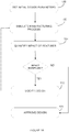
- Figure 1a is an illustrative flowchart of a method for designing a composite component, in accordance with one embodiment.
- Initial design parameters are set 100 as a function of a set of specifications and requirements, or constraints and objectives.
- Design parameters may include geometric ply definitions such as ply thickness, angle tolerances, engineering coordinate system, and ply boundaries.
- Design constraints may impact various mechanical properties, such as strength properties, elastic properties, stability, and physical properties, that are defined by a set of "design allowables". For example, tension, compression, and shear are given theoretical values and test validated at the time of design and these values are known as the design allowable.
- the design allowables are used to obtain safety margins, which correspond to the component's structural capacity beyond the expected loads or actual loads, i.e.
- the design load corresponds to the maximum expected load the component should see when in use.
- a component with a design load of 40 N and a design allowable of 50 N will have a safety margin of 25%.
- Features introduced during the manufacturing phase may have an impact on the design allowables, and thus reduce the safety margins.
- a correction factor may be used to account for the feature.
- the correction factor is intended to represent the difference in the design allowable between a theoretical value and a true value when taking into account the features. Put otherwise, the correction factor adjusts (i.e reduces) the design allowable so as to account for the impact of the manufacturing features on the component's mechanical properties.
- a given feature may have a greater or smaller impact on the margin as a function of its location. If the component is required to have a safety margin of 15% or greater, then the feature that causes the design allowable to fall by 10% is unacceptable. The present method allows this situation to be detected and remedied at the time of design.
- the manufacturing process is simulated 102 and simulation data is generated.
- the geometric ply definitions are used to determine fiber laying trajectories for manufacturing of the composite component.
- the manufacturing process may be simulated using one or more known simulation applications, such as CADFiberTM, FibersimTM, MSC/MD NastranTM, Laminate ModelerTM, MSC PATRANTM, and CATIATM.
- Other known software applications such as Microsoft ExcelTM and Microsoft WordTM, may be used to generate files and/or to organize the results of the simulation such that features introduced by the manufacturing process may be identified.
- the simulation data comprises the raw data from the simulation and must be further processed and/or manipulated to be meaningful.
- the impact of features may be quantified 104 as a function of how the features, at their given locations, impact the properties of the component. This may comprise assessing the effect of a given gap, overlap, angle deviation, and/or steering radius on at least one property of the composite component, such as strength, stability, and part quality.
- the process of quantifying the impact of the features may include 1) comparing the identification and characterization of the gaps, overlaps, angle deviations, and steering radius that are received from the simulation process to coupons or test plans in order to identify the correction factor; and 2) the correction factor is then applied to a location based safety margin (or design allowable) in order to quantify the impact of a given feature at a given location.
- the assessment of the effect of a feature on the properties of the component may have been previously done and resulting correction factors addressing the various impacts have already been provided and compiled into a design allowable database. Quantification may be done on a location-basis, to determine what the impact of a given feature is at a given location. Location-specific correction factors are assigned to the component, and the location-specific factors may then be correlated to a set of varying safety margins associated with location-specific areas of the composite component. Should the impact of all of the features be insignificant, the design is approved 108. If at least one feature has a significant impact, the design is rejected 106.
- the quantitative assessment may be used in a feedback loop to update the design parameters, thus causing the fiber laying trajectories to be modified, in order to generate revised simulation data for the component. Further analysis may be performed on the revised simulation data to determine if the changes have produced the desired outcome.
- the feedback loop provides the ability to direct the features away from zones with less margin and/or higher criticality and generate a set of optimized design parameters for a given composite component. This alternative embodiment is illustrated in figure 1b . Instead of simply being rejected, the design is modified 110 in a manner that may remove the feature and/or reduce its impact. Updated simulation data may then be generated 102 in order to reassess the modified design 104, until an acceptable design is reached and approved 108. Possible modifications to the design include, but are not limited to, adjustments made to angle tolerances at various locations, changes in ply boundaries and adjustments to part thicknesses, trajectories and gap overlap strategy.
- Figure 2 is a flowchart of an exemplary embodiment for quantifying the impact of features 104.
- the simulation data is received 202 and the location and nature of features are extracted 204 from the simulation data.
- the nature of the feature may be any one of a gap, an overlap, a steering radius, an angle deviation, and any occurrence that affects the integrity of the component when manufactured.
- the simulation data as received comprises a three-dimensional (3D) virtual representation of the composite component provided in a reference frame having three axes. Extracting the location of a feature may comprise assigning a position (x, y, z) to a given feature, thus providing its location in relation to the 3D reference frame.
- the simulation data as received may comprise a listing of positions (x, y, z) or (x, y) at which features are present and corresponding values for features.
- each type of feature is present in the composite component.
- a gap is present at position (1, 1, 1), an overlap is present at position (1, 3, 9), an angle deviation feature is present at position (2, 5, 4), and a steering radius feature is present at position (3, 8, 1).
- An absence of a feature at a given position may be assigned a value of zero or simply omitted from the simulation data.
- more than one of each type of feature may be present, and a position may comprise more than one type of feature.
- the listing may also comprise all possible positions (x, y, z) or (x ,y) and have values associated to each one of the potential features, a non-zero value indicating the presence of a feature.
- the features may thus be extracted by parsing the data and identifying the non-zero values and/or the values that exceed a predetermined threshold.
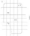
- the location of a feature may be determined using a grid-like pattern overlaid on the virtual representation of the composite component, either on a 2D or 3D view thereof.
- a position may be assigned to the feature as a function of a coordinate of the grid.
- Figure 3a illustrates an embodiment for a 2D view of a virtual representation of a composite component 302.
- an 8 x 5 grid covers the surface of the component 302 and each grid position is provided with an address.
- Features 306a, 306b, 306c, and 306d are found at grid positions B3, B6, D4 and E8 respectively.
- the grid positions may be increased in size, and thus more surface area is covered per grid position, by reducing the number of columns and/or rows of the grid.
- the grid positions may also be reduced in size by increasing the number of columns and/or rows. It may be desired to select the size of the grid to ensure that only one feature is present in any given grid position.
- the grid pattern may be selected as a function of a particular characteristic of the composite component, or using one or more considerations, such as the proximity to an edge, the type of edge, etc.
- Figure 3b illustrates such an embodiment, whereby grid position A1 includes a curved edge and a corner, grid position A2 includes a straight edge, grid position A3 includes a curved edge, and grid position A4 includes no edges.
- feature 306a is located in grid position A1
- features 306b and 306c are located in grid position A2
- feature 306d is located in grid position A3.
- the pattern used to circumscribe the grid positions may be symmetrical, non-symmetrical, uniform, non-uniform, and the grid positions themselves may be of varying shapes and/or sizes.
- location-specific correction factors are assigned to the composite component 206.
- the correction factors are said to be "location-specific" in that more than one correction factor may be assigned to a given part 302, as a function of the location of a feature on the part.
- the correction factor thus applies only to the location to which it has been applied, not to the entire part.
- a lookup table comprising correction factors for corresponding feature values may be used. These correction factors may have been validated or be representative of test results. For example, a gap density of value x may be associated with a correction factor of 10%, a gap density of value y may be associated with a correction factor of 15%, etc.
- correction factors may be associated with single values, ranges of values, combinations of features (i.e. a gap and an angle deviation in a same region), etc. Correction factors may depend on the location of the feature, the nature of the feature, the component property, the materials used in the component, and other elements that may have an impact on the effect of the feature on the component property.
- Figure 4 illustrates an exemplary embodiment of assigning location-specific correction factors, using the grid pattern illustrated in figure 3a .
- Grid positions B3, B6, D4, and E8 are assigned correction factors of 25%, 5%, 12%, and 18%, respectively. These correction factors are determined as a result of the presence of features 306a, 306b, 306c, and 306d found in grid positions B3, B6, D4, and E8.
- the location-specific correction factors may then be correlated to the safety margins of the composite component 208, at each specific location. Correlating refers to establishing the relationship or connection between the location-specific correction factors and the safety margins.
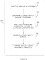
- Figure 5 is an exemplary flowchart illustrating an embodiment for correlating the location-specific correction factors to the safety margins 208.
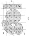
- the surface of the composite component may be partitioned into regions 502, as illustrated in figure 6 .
- four regions 602a, 602b, 602c, and 602d are provided on the surface of the composite component 302, each region characterized by a safety margin 504.
- the location-specific correction factors may be applied to the safety margins 506, as per the example above, by using the true allowables instead of the design allowables.
- Updated safety margins are generated 508 to represent an "as manufactured" design.
- the updated safety margins may be compared to predetermined thresholds 510, such as those set by law or industry standards, or those set by the composite component manufacturer, to determine if the design is acceptable. Should the thresholds be exceeded, the design may be rejected and optionally the design parameters may be modified.
- modifying the design parameters comprises directing the features away from regions of lower safety margins to regions of higher safety margins. This may be done by changing angle tolerances, changing part thicknesses, and/or redefining ply boundaries so that the gaps, overlaps, steering radius, and/or angle deviations occur at a different location on the composite component.
- the design parameters are modified to redistribute the features more uniformly throughout the composite component.
- Some of the robot parameters that may modified to effect these changes are AFP simulation trajectory (a single rosette/coordinate system or a collection of rosettes/coordinate systems by zone or an interpolation between them), ply staggering profile and distances by common orientation, minimum cut length of a tow, and machine layup speed and temperature.
- Figure 7 illustrates an exemplary system 701 for quantifying an impact of features on a composite component to be manufactured using an automated fiber placement (AFP) manufacturing process.
- the system 701 is adapted to be accessed by a plurality of devices 710 via a wireless network 708, such as the Internet, a cellular network, Wi-Fi, or others known to those skilled in the art.
- the devices 710 may comprise any device, such as a laptop computer, a personal digital assistant (PDA), a smartphone, or the like, adapted to communicate over the wireless network 708.
- the system 701 may be provided in part or in its entirety directly on devices 710, as a native application or a web application. It should be understood that cloud computing may also be used such that the system 701 is provided partially or entirely in the cloud.
- the application 706a may be downloaded directly onto devices 710 and application 706n communicates with application 706a via the network 708.
- the system 701 may reside on one or more server(s) 700.
- server(s) 700 For example, a series of servers corresponding to a web server, an application server, and a database server may be used. These servers are all represented by server 700 in Figure 7 .
- the system 701 may comprise, amongst other things, a processor 704 in data communication with a memory 702 and having a plurality of applications 706a, ..., 706n running thereon.
- the processor 704 may access the memory 702 to retrieve data.
- the processor 704 may be any device that can perform operations on data. Examples are a central processing unit (CPU), a microprocessor, and a front-end processor.
- the applications 706a, ..., 706n are coupled to the processor 704 and configured to perform various tasks as explained below in more detail. It should be understood that while the applications 706a, ...., 706n presented herein are illustrated and described as separate entities, they may be combined or separated in a variety of ways. It should be understood that an operating system (not shown) may be used as an intermediary between the processor 704 and the applications 706a, ..., 706n.
- the memory 702 accessible by the processor 704 may receive and store data, such as correction factors, safety margins, location of features, nature of features, etc.
- the memory 702 may be a main memory, such as a high speed Random Access Memory (RAM), or an auxiliary storage unit, such as a hard disk or flash memory.
- RAM Random Access Memory
- auxiliary storage unit such as a hard disk or flash memory.
- the memory 702 may be any other type of memory, such as a Read-Only Memory (ROM), Erasable Programmable Read-Only Memory (EPROM), or optical storage media such as a videodisc and a compact disc.
- ROM Read-Only Memory
- EPROM Erasable Programmable Read-Only Memory
- optical storage media such as a videodisc and a compact disc.
- One or more databases 712 may be integrated directly into the memory 702 or may be provided separately therefrom and remotely from the server 700 (as illustrated). In the case of a remote access to the databases 712, access may occur via any type of network 708, as indicated above.
- the databases 712 may also be accessed through an alternative wireless network or through a wired connection.
- the databases 712 described herein may be provided as collections of data or information organized for rapid search and retrieval by a computer.
- the databases 712 may be structured to facilitate storage, retrieval, modification, and deletion of data in conjunction with various data-processing operations.
- the databases 712 may consist of a file or sets of files that can be broken down into records, each of which consists of one or more fields. Database information may be retrieved through queries using keywords and sorting commands, in order to rapidly search, rearrange, group, and select the field.
- the databases 712 may be any organization of data on a data storage medium, such as one or more servers.
- the databases 712 are secure web servers and Hypertext Transport Protocol Secure (HTTPS) capable of supporting Transport Layer Security (TLS), which is a protocol used for access to the data. Communications to and from the secure web servers may be secured using Secure Sockets Layer (SSL).
- SSL Secure Sockets Layer
- any known communication protocols that enable devices within a computer network to exchange information may be used. Examples of protocols are as follows: IP (Internet Protocol), UDP (User Datagram Protocol), TCP (Transmission Control Protocol), DHCP (Dynamic Host Configuration Protocol), HTTP (Hypertext Transfer Protocol), FTP (File Transfer Protocol), Telnet (Telnet Remote Protocol), SSH (Secure Shell Remote Protocol).
- a feature quantifying module 804 receives simulation data from a simulation module 802, which may form part of the system 701 but be separate from application 706a, as illustrated.
- the simulation module 802 may form part of application 706a.
- the simulation module 802 may be remote from system 701, and simulation data may be received via network 708.
- a design modification module 806 is operatively connected to the feature quantifying module 804 and may be separate from the application 706a while forming a part of the system 701, integrated into application 706a, or remote from system 701 and accessible via network 708.
- the design modification module 806 may be configured to modify design parameters when a design is rejected or identified as requiring modification.
- Figure 9 illustrates an exemplary embodiment of the feature quantifying module 804.
- a feature ID module 902 is configured to receive a set of simulation data related to the virtual simulation of the AFP manufacturing process for the composite component using a set of fiber laying trajectories, and extract the location and nature of the features. As described above, extraction of the location and nature of the features may be done using various techniques, such as based on 2D and 3D images of a manufactured component. In some embodiments, the actual location and nature of the features is determined by the simulation module 802 and the feature ID module 902 will receive a data stream and extract the location and nature of the features from the data stream.
- a correction factors module 904 is configured to assign location-specific correction factors to the composite component as a function of the impact of the features at the corresponding locations.
- a safety margins module 906 is configured to correlate the location specific factors to allowable safety margins at each one of the corresponding locations.
- the safety margins module 906 may be configured to partition a surface of the composite component into a plurality of regions and determine the allowable safety margins for the plurality of regions. Alternatively, such partitioning may be performed outside of the feature quantifying module 804 and fed to the safety margins module 906.
- the correction factors module 904 may be configured to apply the location-specific correction factors to the allowable safety margins for regions having features located therein, and the safety margins module 906 may generate updated safety margins per region.
- the safety margins module 906 may be configured to reject the design when at least one of the updated safety margins falls below a predetermined threshold.
- the safety margins module 906 may also be configured to communicate with the design modification module 806 to request changes to the design.
- the design modification module 806 may be configured to receive a data signal from the feature quantifying module 804.
- the data signal may be a rejection signal when a set of design parameters have been rejected for failure to meet a criteria, such as a threshold for safety margins of the component once correction factors have been applied.
- the rejection signal may be used by the design modification module 806 to trigger modifications to the design parameters, such as changes to angle tolerances at various locations, changes in ply boundaries and adjustments to part thicknesses, trajectories and gap overlap strategy.
- the design modification module 806 may be configured to suggest certain modifications as a function of the type of feature and the location of the feature. The level of impact a feature has on the design may also be a factor in determining how the design parameters are changed.
- the design modification module 806 may modify a fiber laying trajectory to displace the feature to a zone of lower criticality. If the updated safety margin is significantly below a predetermined threshold, the design modification module may increase ply thickness to remedy the situation. The design modification module 806 may make changes directly to the design parameters, or may provide recommendations to be applied to the design parameters.
- the data signal received by the design modification module 806 is a verification request and the design modification module 806 compares updated safety margins to predetermined thresholds. The determination as to whether the design parameters are acceptable or not may then be performed by the design modification module 806.
- the design modification module 806 may communicate with the simulation module 802 to perform a new simulation using updated design parameters.
- the feature quantifying module 804 may be configured to output a signal (i.e. approved/rejected), display a message on a display device (i.e. approved/rejected or details regarding rejection), or provide graphical information on a display device.
- a signal i.e. approved/rejected
- the component as illustrated in figure 6 with the safety margin zones may be displayed, and the zones may be color coded to indicate which ones are acceptable and which ones are rejected.
- a color code such as red for rejected, green for accepted, and yellow for borderline may be used.
- Other color codes may also be used, as well as other types of visual indicators.
- the different features may themselves be color-coded for visual display, and different levels of impact may be displayed visually using various techniques.
- the present invention can be carried out as a method, can be embodied in a system, or can be provided on a computer readable medium having stored thereon program code executable by a processor.
- the embodiments of the invention described above are intended to be exemplary only. The scope of the invention is therefore intended to be limited solely by the scope of the appended claims.
Landscapes
- Engineering & Computer Science (AREA)
- Physics & Mathematics (AREA)
- General Physics & Mathematics (AREA)
- Human Computer Interaction (AREA)
- Manufacturing & Machinery (AREA)
- Automation & Control Theory (AREA)
- Theoretical Computer Science (AREA)
- Computer Hardware Design (AREA)
- Geometry (AREA)
- General Engineering & Computer Science (AREA)
- Evolutionary Computation (AREA)
- Moulding By Coating Moulds (AREA)
- Management, Administration, Business Operations System, And Electronic Commerce (AREA)
- Image Analysis (AREA)
Claims (22)
- Computerimplementiertes Verfahren zum Quantifizieren eines Einflusses von Merkmalen auf eine herzustellende Verbundkomponente unter Anwendung eines automatisierten Herstellungsprozesses, wobei sich die Merkmale aus dem Herstellungsprozess ergeben, wobei das Verfahren Folgendes umfasst:Empfangen eines Satzes an Simulationsdaten in Bezug auf eine virtuelle Simulation des Herstellungsprozesses für die Verbundkomponente unter Anwendung eines Satzes an Gestaltungsparametern (100);Extrahieren einer Stelle und einer Art der Merkmale von den Simulationsdaten (204);Zuweisen von stellenspezifischen Korrekturfaktoren an die Verbundkomponente in Abhängigkeit eines Einflusses der Merkmale an entsprechenden Stellen (206); undKorrelieren der stellenspezifischen Korrekturfaktoren mit annehmbaren Sicherheitsmargen an jeder der entsprechenden Stellen (208).
- Verfahren nach Anspruch 1, wobei das Korrelieren der stellenspezifischen Korrekturfaktoren mit annehmbaren Sicherheitsmargen Folgendes umfasst:Unterteilen einer Fläche der Verbundkomponente in eine Vielzahl von Regionen (502);Bestimmen der annehmbaren Sicherheitsmargen für die Vielzahl von Regionen (504);Anwenden der stellenspezifischen Korrekturfaktoren auf die annehmbaren Sicherheitsmargen für Regionen, die sich darin befindende Merkmale aufweisen (506); undErzeugen von aktualisierten Sicherheitsmargen je Region (508).
- Verfahren nach Anspruch 2, ferner umfassend das Zurückweisen der Gestaltungsparameter (106), wenn zumindest eine der aktualisierten Sicherheitsmargen unter einen zuvor festgelegten Schwellenwert fällt.
- Verfahren nach Anspruch 2, ferner umfassend das Modifizieren der Gestaltungsparameter (110), wenn zumindest eine der aktualisierten Sicherheitsmargen unter einen zuvor festgelegten Schwellenwert fällt.
- Verfahren nach Anspruch 4, wobei das Modifizieren der Gestaltungsparameter das Modifizieren von Winkeltoleranzen umfasst.
- Verfahren nach Anspruch 4, wobei das Modifizieren der Gestaltungsparameter das Lenken von zumindest einem Merkmal aus einer Region einer niedrigeren Sicherheitsmarge zu einer Region einer höheren Sicherheitsmarge umfasst.
- Verfahren nach Anspruch 2, ferner umfassend das Modifizieren der Gestaltungsparameter, um die Merkmale in der gesamten Verbundkomponente umzuverteilen.
- Verfahren nach Anspruch 7, ferner umfassend sich wiederholende Schritte des Empfangens eines Satzes an Simulationsdaten, Extrahierens einer Stelle und einer Art der Merkmale, Zuweisens von stellenspezifischen Korrekturfaktoren und Korrelierens der stellenspezifischen Korrekturfaktoren mit den modifizierten Gestaltungsparametern.
- Verfahren nach Anspruch 8, wobei das Wiederholen das weitere Modifizieren der Gestaltungsparameter und das Fortsetzen der Wiederholung, bis eine annehmbare Gestaltung erhalten ist, umfasst.
- Verfahren nach einem der Ansprüche 1 bis 9, wobei das Zuweisen von stellenspezifischen Korrekturfaktoren das Abrufen der stellenspezifischen Korrekturfaktoren aus einer Nachschlagetabelle umfasst, die zuvor festgelegte Korrekturfaktoren für entsprechende Merkmalswerte umfasst, wobei die zuvor festgelegten Korrekturfaktoren validiert worden sind oder repräsentativ für Testergebnisse sind.
- Verfahren nach einem der Ansprüche 1 bis 10, wobei der automatisierte Herstellungsprozess ein automatisierter Faserplatzierungsprozess ist.
- System (700) zum Quantifizieren eines Einflusses von Merkmalen auf eine herzustellende Verbundkomponente unter Anwendung eines automatisierten Herstellungsprozesses, wobei sich die Merkmale aus dem Herstellungsprozess ergeben, wobei das System Folgendes umfasst:einen Speicher (702);einen Prozessor (704); undzumindest eine Anwendung (706A), die in dem Speicher gespeichert ist und für Folgendes durch den Prozessor ausführbar ist:Empfangen eines Satzes an Simulationsdaten in Bezug auf eine virtuelle Simulation des Herstellungsprozesses für die Verbundkomponente unter Anwendung eines Satzes an Gestaltungsparametern;Extrahieren einer Stelle und einer Art der Merkmale von den Simulationsdaten;Zuweisen von stellenspezifischen Korrekturfaktoren an die Verbundkomponente in Abhängigkeit eines Einflusses der Merkmale an entsprechenden Stellen; undKorrelieren der stellenspezifischen Korrekturfaktoren mit annehmbaren Sicherheitsmargen an jeder der entsprechenden Stellen.
- System nach Anspruch 12, wobei das Korrelieren der stellenspezifischen Korrekturfaktoren mit annehmbaren Sicherheitsmargen Folgendes umfasst:Unterteilen einer Fläche der Verbundkomponente in eine Vielzahl von Regionen;Bestimmen der annehmbaren Sicherheitsmargen für die Vielzahl von Regionen;Anwenden der stellenspezifischen Korrekturfaktoren auf die annehmbaren Sicherheitsmargen für Regionen, die sich darin befindende Merkmale aufweisen; undErzeugen von aktualisierten Sicherheitsmargen je Region.
- System nach Anspruch 13, wobei die zumindest eine Anwendung ferner konfiguriert ist, um die Gestaltungsparameter zurückzuweisen, wenn zumindest eine der aktualisierten Sicherheitsmargen unter einen zuvor festgelegten Schwellenwert fällt.
- System nach Anspruch 13, wobei die zumindest eine Anwendung ferner konfiguriert ist, um die Gestaltungsparameter zu modifizieren, wenn zumindest eine der aktualisierten Sicherheitsmargen unter einen zuvor festgelegten Schwellenwert fällt.
- System nach Anspruch 15, wobei das Modifizieren der Gestaltungsparameter das Modifizieren von Winkeltoleranzen umfasst.
- System nach Anspruch 15, wobei das Modifizieren der Gestaltungsparameter das Lenken von zumindest einem der Merkmale aus einer Region einer niedrigeren Sicherheitsmarge zu einer Region einer höheren Sicherheitsmarge umfasst.
- System nach Anspruch 13, wobei die zumindest eine Anwendung ferner konfiguriert ist, um die Gestaltungsparameter zu modifizieren, um die Merkmale in der gesamten Verbundkomponente umzuverteilen.
- System nach Anspruch 18, wobei die zumindest eine Anwendung ferner für sich wiederholende Schritte des Empfangens eines Satzes an Simulationsdaten, Extrahierens einer Stelle und einer Art von Merkmalen, Zuweisens von stellenspezifischen Korrekturfaktoren und Korrelierens der stellenspezifischen Korrekturfaktoren mit den modifizierten Gestaltungsparametern konfiguriert ist.
- System nach Anspruch 19, wobei das Wiederholen das weitere Modifizieren der Gestaltungsparameter und das Fortsetzen der Wiederholung, bis eine annehmbare Gestaltung erhalten ist, umfasst.
- System nach einem der Ansprüche 12 bis 20, wobei das Zuweisen von stellenspezifischen Korrekturfaktoren das Abrufen der stellenspezifischen Korrekturfaktoren aus einer Nachschlagetabelle umfasst, die zuvor festgelegte Korrekturfaktoren für entsprechende Merkmalswerte umfasst, wobei die zuvor festgelegten Korrekturfaktoren validiert worden sind oder repräsentativ für Testergebnisse sind.
- System nach einem der Ansprüche 12 bis 21, wobei der automatisierte Herstellungsprozess ein automatisierter Faserplatzierungsprozess ist.
Applications Claiming Priority (2)
| Application Number | Priority Date | Filing Date | Title |
|---|---|---|---|
| US201461990840P | 2014-05-09 | 2014-05-09 | |
| PCT/IB2015/053175 WO2015170233A1 (en) | 2014-05-09 | 2015-04-30 | A method and system for quantifying the impact of features on composite components |
Publications (2)
| Publication Number | Publication Date |
|---|---|
| EP3140706A1 EP3140706A1 (de) | 2017-03-15 |
| EP3140706B1 true EP3140706B1 (de) | 2018-06-27 |
Family
ID=53264696
Family Applications (1)
| Application Number | Title | Priority Date | Filing Date |
|---|---|---|---|
| EP15724366.8A Not-in-force EP3140706B1 (de) | 2014-05-09 | 2015-04-30 | Verfahren und system zur quantifizierung der auswirkung von merkmalen auf verbundbauteile |
Country Status (5)
| Country | Link |
|---|---|
| US (1) | US10380279B2 (de) |
| EP (1) | EP3140706B1 (de) |
| CN (1) | CN106462144B (de) |
| CA (1) | CA2948103A1 (de) |
| WO (1) | WO2015170233A1 (de) |
Families Citing this family (2)
| Publication number | Priority date | Publication date | Assignee | Title |
|---|---|---|---|---|
| US10073440B1 (en) * | 2018-02-13 | 2018-09-11 | University Of Central Florida Research Foundation, Inc. | Method for the design and manufacture of composites having tunable physical properties |
| CN114594811B (zh) * | 2020-12-03 | 2023-08-25 | 上海飞机制造有限公司 | 材料铺放过程中温度调整方法、装置、设备及存储介质 |
Family Cites Families (22)
| Publication number | Priority date | Publication date | Assignee | Title |
|---|---|---|---|---|
| US5562788A (en) | 1994-09-20 | 1996-10-08 | The Boeing Company | Composite material laser flaw detection |
| US6799081B1 (en) | 2000-11-15 | 2004-09-28 | Mcdonnell Douglas Corporation | Fiber placement and fiber steering systems and corresponding software for composite structures |
| CN1141643C (zh) | 2002-04-23 | 2004-03-10 | 上海交通大学 | 白车身数字化封样方法 |
| US20030229476A1 (en) | 2002-06-07 | 2003-12-11 | Lohitsa, Inc. | Enhancing dynamic characteristics in an analytical model |
| US6871684B2 (en) | 2002-08-13 | 2005-03-29 | The Boeing Company | System for identifying defects in a composite structure |
| US7289656B2 (en) | 2003-12-02 | 2007-10-30 | The Boeing Company | Systems and methods for determining inconsistency characteristics of a composite structure |
| US7193696B2 (en) | 2004-04-12 | 2007-03-20 | United Technologies Corporation | Systems and methods for using light to indicate defect locations on a composite structure |
| US7424902B2 (en) | 2004-11-24 | 2008-09-16 | The Boeing Company | In-process vision detection of flaw and FOD characteristics |
| US7835567B2 (en) | 2006-01-24 | 2010-11-16 | Ingersoll Machine Tools, Inc. | Visual fiber placement inspection |
| US7978328B2 (en) | 2006-03-28 | 2011-07-12 | The Boeing Company | Vision inspection system device and method |
| US7555404B2 (en) | 2007-08-09 | 2009-06-30 | The Boeing Company | Methods and systems for automated ply boundary and orientation inspection |
| US7807002B2 (en) | 2007-12-17 | 2010-10-05 | The Boeing Company | Verification of tow cut for automatic fiber placement |
| US20090234616A1 (en) * | 2008-02-21 | 2009-09-17 | Syncretek Llc | Automatic Repair Planning and Part Archival System (ARPPAS) |
| DE102008012055B3 (de) | 2008-02-29 | 2009-10-01 | Airbus Deutschland Gmbh | Verfahren zum Toleranzausgleich zwischen zwei Faserverbundbauteilen |
| EP2342073B1 (de) | 2008-10-23 | 2016-11-23 | Hexcel Reinforcements | Neuartiges verstärkungsmaterial, das zur herstellung von verbundwerkstoffen geeignet ist |
| US8108058B2 (en) | 2009-02-09 | 2012-01-31 | The Boeing Company | Method of analyzing composite structures |
| US20110208487A1 (en) | 2010-02-19 | 2011-08-25 | Looney Michael Timothy | Computer based modeling of processed fibrous materials |
| CN102649210B (zh) | 2011-02-24 | 2015-07-22 | 宝山钢铁股份有限公司 | 增加旋压工序的轻量化轮辋制造方法 |
| WO2013105995A2 (en) | 2011-02-25 | 2013-07-18 | Board Of Supervisors Of Louisiana State University And Agricultural And Mechanical College | Fatigue monitoring for composite materials |
| US20130018499A1 (en) | 2011-07-12 | 2013-01-17 | The Boeing Company | Producibility analysis during engineering design of composite parts |
| US20130050685A1 (en) | 2011-08-23 | 2013-02-28 | The Boeing Company | Composite structure having an embedded sensing system |
| CA3125846A1 (en) * | 2012-03-20 | 2013-09-26 | Verifi Technologies, Llc | Method and system for non-destructive testing of composites |
-
2015
- 2015-04-30 CA CA2948103A patent/CA2948103A1/en not_active Abandoned
- 2015-04-30 US US15/309,634 patent/US10380279B2/en active Active
- 2015-04-30 CN CN201580024642.8A patent/CN106462144B/zh not_active Expired - Fee Related
- 2015-04-30 WO PCT/IB2015/053175 patent/WO2015170233A1/en active Application Filing
- 2015-04-30 EP EP15724366.8A patent/EP3140706B1/de not_active Not-in-force
Non-Patent Citations (1)
| Title |
|---|
| None * |
Also Published As
| Publication number | Publication date |
|---|---|
| CN106462144A (zh) | 2017-02-22 |
| WO2015170233A1 (en) | 2015-11-12 |
| EP3140706A1 (de) | 2017-03-15 |
| CA2948103A1 (en) | 2015-11-12 |
| US10380279B2 (en) | 2019-08-13 |
| CN106462144B (zh) | 2019-06-04 |
| US20170242942A1 (en) | 2017-08-24 |
Similar Documents
| Publication | Publication Date | Title |
|---|---|---|
| CN107526862B (zh) | 用于分析包括组成部件的结构的修复的装置和方法 | |
| US9691049B2 (en) | Master bill of materials creation | |
| CN101635051B (zh) | 边界元素提取方法及其计算机系统 | |
| US10611086B2 (en) | System and method for evaluating additive manufacturing index | |
| US9811610B2 (en) | Systems and methods for bevel feature recognition and bevel profile generation | |
| EP3140706B1 (de) | Verfahren und system zur quantifizierung der auswirkung von merkmalen auf verbundbauteile | |
| JP2018521434A (ja) | シート材料における機械切断方法及びシステム | |
| CN107622144B (zh) | 基于序贯方法的区间不确定性条件下多学科可靠性优化设计方法 | |
| Lavrentyieva et al. | Identifying the objects in the structure of an e-model by means of identified formal parameters in the design and engineering environment | |
| CN105138850B (zh) | 一种民用飞机系统维修时间间隔计算方法 | |
| US20170336778A1 (en) | On-demand tool kits | |
| EP2709835B1 (de) | Schablonensystem für gebondete nacharbeit | |
| US9152743B2 (en) | Computer process for determining best-fitting materials for constructing architectural surfaces | |
| CA2959599A1 (en) | Method and system for determining sampling plan for inspection of composite components | |
| Korneev et al. | THE ANALYSIS OF TECHNOLOGICAL TRAJECTORIES BASED ON THE TREE CONSTRUCTION. | |
| WO2013116859A1 (en) | Computer process for determining best-fitting materials for constructing architectural surfaces | |
| JP6890431B2 (ja) | 多層複合部品のためのプライ最適化実行可能性分析 | |
| CN110088755B (zh) | 用于协助决定选择待组装部件的方法、系统和存储介质 | |
| KR102194212B1 (ko) | 정보 관리 시스템 | |
| JP2013134651A (ja) | 在庫中間製品に対する製品引当方法及び製品引当装置 | |
| Clark et al. | Digital process twins: a modular approach for surface conditioning and process optimization | |
| US20220067242A1 (en) | Modifying a finite element mesh | |
| Dannenberg et al. | Model Based Optimization of Forging Process Chains under the Consideration of Penalty Functions | |
| KR102263772B1 (ko) | 프로세스 마이닝을 응용한 블록 물류 프로세스 군집화 방법 및 장치 | |
| Horváth et al. | Integrated modeling for corporate knowledge controlled lifecycle product definition |
Legal Events
| Date | Code | Title | Description |
|---|---|---|---|
| STAA | Information on the status of an ep patent application or granted ep patent |
Free format text: STATUS: THE INTERNATIONAL PUBLICATION HAS BEEN MADE |
|
| PUAI | Public reference made under article 153(3) epc to a published international application that has entered the european phase |
Free format text: ORIGINAL CODE: 0009012 |
|
| STAA | Information on the status of an ep patent application or granted ep patent |
Free format text: STATUS: REQUEST FOR EXAMINATION WAS MADE |
|
| 17P | Request for examination filed |
Effective date: 20161115 |
|
| AK | Designated contracting states |
Kind code of ref document: A1 Designated state(s): AL AT BE BG CH CY CZ DE DK EE ES FI FR GB GR HR HU IE IS IT LI LT LU LV MC MK MT NL NO PL PT RO RS SE SI SK SM TR |
|
| AX | Request for extension of the european patent |
Extension state: BA ME |
|
| DAV | Request for validation of the european patent (deleted) | ||
| DAX | Request for extension of the european patent (deleted) | ||
| GRAP | Despatch of communication of intention to grant a patent |
Free format text: ORIGINAL CODE: EPIDOSNIGR1 |
|
| STAA | Information on the status of an ep patent application or granted ep patent |
Free format text: STATUS: GRANT OF PATENT IS INTENDED |
|
| INTG | Intention to grant announced |
Effective date: 20180124 |
|
| GRAS | Grant fee paid |
Free format text: ORIGINAL CODE: EPIDOSNIGR3 |
|
| GRAA | (expected) grant |
Free format text: ORIGINAL CODE: 0009210 |
|
| STAA | Information on the status of an ep patent application or granted ep patent |
Free format text: STATUS: THE PATENT HAS BEEN GRANTED |
|
| AK | Designated contracting states |
Kind code of ref document: B1 Designated state(s): AL AT BE BG CH CY CZ DE DK EE ES FI FR GB GR HR HU IE IS IT LI LT LU LV MC MK MT NL NO PL PT RO RS SE SI SK SM TR |
|
| REG | Reference to a national code |
Ref country code: GB Ref legal event code: FG4D |
|
| REG | Reference to a national code |
Ref country code: AT Ref legal event code: REF Ref document number: 1012859 Country of ref document: AT Kind code of ref document: T Effective date: 20180715 |
|
| REG | Reference to a national code |
Ref country code: IE Ref legal event code: FG4D |
|
| REG | Reference to a national code |
Ref country code: DE Ref legal event code: R096 Ref document number: 602015012758 Country of ref document: DE |
|
| PG25 | Lapsed in a contracting state [announced via postgrant information from national office to epo] |
Ref country code: SE Free format text: LAPSE BECAUSE OF FAILURE TO SUBMIT A TRANSLATION OF THE DESCRIPTION OR TO PAY THE FEE WITHIN THE PRESCRIBED TIME-LIMIT Effective date: 20180627 Ref country code: LT Free format text: LAPSE BECAUSE OF FAILURE TO SUBMIT A TRANSLATION OF THE DESCRIPTION OR TO PAY THE FEE WITHIN THE PRESCRIBED TIME-LIMIT Effective date: 20180627 Ref country code: BG Free format text: LAPSE BECAUSE OF FAILURE TO SUBMIT A TRANSLATION OF THE DESCRIPTION OR TO PAY THE FEE WITHIN THE PRESCRIBED TIME-LIMIT Effective date: 20180927 Ref country code: FI Free format text: LAPSE BECAUSE OF FAILURE TO SUBMIT A TRANSLATION OF THE DESCRIPTION OR TO PAY THE FEE WITHIN THE PRESCRIBED TIME-LIMIT Effective date: 20180627 Ref country code: NO Free format text: LAPSE BECAUSE OF FAILURE TO SUBMIT A TRANSLATION OF THE DESCRIPTION OR TO PAY THE FEE WITHIN THE PRESCRIBED TIME-LIMIT Effective date: 20180927 |
|
| REG | Reference to a national code |
Ref country code: NL Ref legal event code: MP Effective date: 20180627 |
|
| REG | Reference to a national code |
Ref country code: LT Ref legal event code: MG4D |
|
| PG25 | Lapsed in a contracting state [announced via postgrant information from national office to epo] |
Ref country code: LV Free format text: LAPSE BECAUSE OF FAILURE TO SUBMIT A TRANSLATION OF THE DESCRIPTION OR TO PAY THE FEE WITHIN THE PRESCRIBED TIME-LIMIT Effective date: 20180627 Ref country code: RS Free format text: LAPSE BECAUSE OF FAILURE TO SUBMIT A TRANSLATION OF THE DESCRIPTION OR TO PAY THE FEE WITHIN THE PRESCRIBED TIME-LIMIT Effective date: 20180627 Ref country code: GR Free format text: LAPSE BECAUSE OF FAILURE TO SUBMIT A TRANSLATION OF THE DESCRIPTION OR TO PAY THE FEE WITHIN THE PRESCRIBED TIME-LIMIT Effective date: 20180928 Ref country code: HR Free format text: LAPSE BECAUSE OF FAILURE TO SUBMIT A TRANSLATION OF THE DESCRIPTION OR TO PAY THE FEE WITHIN THE PRESCRIBED TIME-LIMIT Effective date: 20180627 |
|
| REG | Reference to a national code |
Ref country code: AT Ref legal event code: MK05 Ref document number: 1012859 Country of ref document: AT Kind code of ref document: T Effective date: 20180627 |
|
| PG25 | Lapsed in a contracting state [announced via postgrant information from national office to epo] |
Ref country code: NL Free format text: LAPSE BECAUSE OF FAILURE TO SUBMIT A TRANSLATION OF THE DESCRIPTION OR TO PAY THE FEE WITHIN THE PRESCRIBED TIME-LIMIT Effective date: 20180627 |
|
| PG25 | Lapsed in a contracting state [announced via postgrant information from national office to epo] |
Ref country code: SK Free format text: LAPSE BECAUSE OF FAILURE TO SUBMIT A TRANSLATION OF THE DESCRIPTION OR TO PAY THE FEE WITHIN THE PRESCRIBED TIME-LIMIT Effective date: 20180627 Ref country code: IS Free format text: LAPSE BECAUSE OF FAILURE TO SUBMIT A TRANSLATION OF THE DESCRIPTION OR TO PAY THE FEE WITHIN THE PRESCRIBED TIME-LIMIT Effective date: 20181027 Ref country code: PL Free format text: LAPSE BECAUSE OF FAILURE TO SUBMIT A TRANSLATION OF THE DESCRIPTION OR TO PAY THE FEE WITHIN THE PRESCRIBED TIME-LIMIT Effective date: 20180627 Ref country code: EE Free format text: LAPSE BECAUSE OF FAILURE TO SUBMIT A TRANSLATION OF THE DESCRIPTION OR TO PAY THE FEE WITHIN THE PRESCRIBED TIME-LIMIT Effective date: 20180627 Ref country code: AT Free format text: LAPSE BECAUSE OF FAILURE TO SUBMIT A TRANSLATION OF THE DESCRIPTION OR TO PAY THE FEE WITHIN THE PRESCRIBED TIME-LIMIT Effective date: 20180627 Ref country code: RO Free format text: LAPSE BECAUSE OF FAILURE TO SUBMIT A TRANSLATION OF THE DESCRIPTION OR TO PAY THE FEE WITHIN THE PRESCRIBED TIME-LIMIT Effective date: 20180627 Ref country code: CZ Free format text: LAPSE BECAUSE OF FAILURE TO SUBMIT A TRANSLATION OF THE DESCRIPTION OR TO PAY THE FEE WITHIN THE PRESCRIBED TIME-LIMIT Effective date: 20180627 |
|
| PG25 | Lapsed in a contracting state [announced via postgrant information from national office to epo] |
Ref country code: ES Free format text: LAPSE BECAUSE OF FAILURE TO SUBMIT A TRANSLATION OF THE DESCRIPTION OR TO PAY THE FEE WITHIN THE PRESCRIBED TIME-LIMIT Effective date: 20180627 Ref country code: SM Free format text: LAPSE BECAUSE OF FAILURE TO SUBMIT A TRANSLATION OF THE DESCRIPTION OR TO PAY THE FEE WITHIN THE PRESCRIBED TIME-LIMIT Effective date: 20180627 Ref country code: IT Free format text: LAPSE BECAUSE OF FAILURE TO SUBMIT A TRANSLATION OF THE DESCRIPTION OR TO PAY THE FEE WITHIN THE PRESCRIBED TIME-LIMIT Effective date: 20180627 |
|
| REG | Reference to a national code |
Ref country code: DE Ref legal event code: R097 Ref document number: 602015012758 Country of ref document: DE |
|
| PLBE | No opposition filed within time limit |
Free format text: ORIGINAL CODE: 0009261 |
|
| STAA | Information on the status of an ep patent application or granted ep patent |
Free format text: STATUS: NO OPPOSITION FILED WITHIN TIME LIMIT |
|
| PG25 | Lapsed in a contracting state [announced via postgrant information from national office to epo] |
Ref country code: DK Free format text: LAPSE BECAUSE OF FAILURE TO SUBMIT A TRANSLATION OF THE DESCRIPTION OR TO PAY THE FEE WITHIN THE PRESCRIBED TIME-LIMIT Effective date: 20180627 |
|
| 26N | No opposition filed |
Effective date: 20190328 |
|
| PG25 | Lapsed in a contracting state [announced via postgrant information from national office to epo] |
Ref country code: SI Free format text: LAPSE BECAUSE OF FAILURE TO SUBMIT A TRANSLATION OF THE DESCRIPTION OR TO PAY THE FEE WITHIN THE PRESCRIBED TIME-LIMIT Effective date: 20180627 |
|
| PG25 | Lapsed in a contracting state [announced via postgrant information from national office to epo] |
Ref country code: AL Free format text: LAPSE BECAUSE OF FAILURE TO SUBMIT A TRANSLATION OF THE DESCRIPTION OR TO PAY THE FEE WITHIN THE PRESCRIBED TIME-LIMIT Effective date: 20180627 |
|
| REG | Reference to a national code |
Ref country code: CH Ref legal event code: PL |
|
| REG | Reference to a national code |
Ref country code: BE Ref legal event code: MM Effective date: 20190430 |
|
| PG25 | Lapsed in a contracting state [announced via postgrant information from national office to epo] |
Ref country code: LU Free format text: LAPSE BECAUSE OF NON-PAYMENT OF DUE FEES Effective date: 20190430 Ref country code: MC Free format text: LAPSE BECAUSE OF FAILURE TO SUBMIT A TRANSLATION OF THE DESCRIPTION OR TO PAY THE FEE WITHIN THE PRESCRIBED TIME-LIMIT Effective date: 20180627 |
|
| PG25 | Lapsed in a contracting state [announced via postgrant information from national office to epo] |
Ref country code: LI Free format text: LAPSE BECAUSE OF NON-PAYMENT OF DUE FEES Effective date: 20190430 Ref country code: CH Free format text: LAPSE BECAUSE OF NON-PAYMENT OF DUE FEES Effective date: 20190430 |
|
| PG25 | Lapsed in a contracting state [announced via postgrant information from national office to epo] |
Ref country code: BE Free format text: LAPSE BECAUSE OF NON-PAYMENT OF DUE FEES Effective date: 20190430 |
|
| PG25 | Lapsed in a contracting state [announced via postgrant information from national office to epo] |
Ref country code: TR Free format text: LAPSE BECAUSE OF FAILURE TO SUBMIT A TRANSLATION OF THE DESCRIPTION OR TO PAY THE FEE WITHIN THE PRESCRIBED TIME-LIMIT Effective date: 20180627 |
|
| PG25 | Lapsed in a contracting state [announced via postgrant information from national office to epo] |
Ref country code: IE Free format text: LAPSE BECAUSE OF NON-PAYMENT OF DUE FEES Effective date: 20190430 |
|
| PG25 | Lapsed in a contracting state [announced via postgrant information from national office to epo] |
Ref country code: PT Free format text: LAPSE BECAUSE OF FAILURE TO SUBMIT A TRANSLATION OF THE DESCRIPTION OR TO PAY THE FEE WITHIN THE PRESCRIBED TIME-LIMIT Effective date: 20181029 |
|
| PGFP | Annual fee paid to national office [announced via postgrant information from national office to epo] |
Ref country code: FR Payment date: 20200420 Year of fee payment: 6 Ref country code: DE Payment date: 20200420 Year of fee payment: 6 |
|
| PGFP | Annual fee paid to national office [announced via postgrant information from national office to epo] |
Ref country code: GB Payment date: 20200427 Year of fee payment: 6 |
|
| PG25 | Lapsed in a contracting state [announced via postgrant information from national office to epo] |
Ref country code: CY Free format text: LAPSE BECAUSE OF FAILURE TO SUBMIT A TRANSLATION OF THE DESCRIPTION OR TO PAY THE FEE WITHIN THE PRESCRIBED TIME-LIMIT Effective date: 20180627 |
|
| PG25 | Lapsed in a contracting state [announced via postgrant information from national office to epo] |
Ref country code: HU Free format text: LAPSE BECAUSE OF FAILURE TO SUBMIT A TRANSLATION OF THE DESCRIPTION OR TO PAY THE FEE WITHIN THE PRESCRIBED TIME-LIMIT; INVALID AB INITIO Effective date: 20150430 Ref country code: MT Free format text: LAPSE BECAUSE OF FAILURE TO SUBMIT A TRANSLATION OF THE DESCRIPTION OR TO PAY THE FEE WITHIN THE PRESCRIBED TIME-LIMIT Effective date: 20180627 |
|
| REG | Reference to a national code |
Ref country code: DE Ref legal event code: R119 Ref document number: 602015012758 Country of ref document: DE |
|
| GBPC | Gb: european patent ceased through non-payment of renewal fee |
Effective date: 20210430 |
|
| PG25 | Lapsed in a contracting state [announced via postgrant information from national office to epo] |
Ref country code: DE Free format text: LAPSE BECAUSE OF NON-PAYMENT OF DUE FEES Effective date: 20211103 Ref country code: GB Free format text: LAPSE BECAUSE OF NON-PAYMENT OF DUE FEES Effective date: 20210430 Ref country code: FR Free format text: LAPSE BECAUSE OF NON-PAYMENT OF DUE FEES Effective date: 20210430 |
|
| PG25 | Lapsed in a contracting state [announced via postgrant information from national office to epo] |
Ref country code: MK Free format text: LAPSE BECAUSE OF FAILURE TO SUBMIT A TRANSLATION OF THE DESCRIPTION OR TO PAY THE FEE WITHIN THE PRESCRIBED TIME-LIMIT Effective date: 20180627 |