EP3140591B1 - Generating a light emission pattern in a far field - Google Patents
Generating a light emission pattern in a far field Download PDFInfo
- Publication number
- EP3140591B1 EP3140591B1 EP15721634.2A EP15721634A EP3140591B1 EP 3140591 B1 EP3140591 B1 EP 3140591B1 EP 15721634 A EP15721634 A EP 15721634A EP 3140591 B1 EP3140591 B1 EP 3140591B1
- Authority
- EP
- European Patent Office
- Prior art keywords
- phosphor
- light
- light emission
- lighting apparatus
- illumination
- Prior art date
- Legal status (The legal status is an assumption and is not a legal conclusion. Google has not performed a legal analysis and makes no representation as to the accuracy of the status listed.)
- Not-in-force
Links
- OAICVXFJPJFONN-UHFFFAOYSA-N Phosphorus Chemical compound [P] OAICVXFJPJFONN-UHFFFAOYSA-N 0.000 claims description 203
- 238000005286 illumination Methods 0.000 claims description 52
- 239000000969 carrier Substances 0.000 claims description 16
- 238000009826 distribution Methods 0.000 claims description 11
- 238000009828 non-uniform distribution Methods 0.000 claims description 2
- 238000009827 uniform distribution Methods 0.000 claims description 2
- 238000006243 chemical reaction Methods 0.000 description 11
- 230000005855 radiation Effects 0.000 description 11
- 239000004065 semiconductor Substances 0.000 description 9
- 230000008859 change Effects 0.000 description 7
- 230000008901 benefit Effects 0.000 description 6
- 238000006073 displacement reaction Methods 0.000 description 6
- 239000000203 mixture Substances 0.000 description 6
- 230000003287 optical effect Effects 0.000 description 4
- 238000007493 shaping process Methods 0.000 description 4
- 230000003595 spectral effect Effects 0.000 description 4
- 238000001914 filtration Methods 0.000 description 3
- 239000002184 metal Substances 0.000 description 3
- 238000000034 method Methods 0.000 description 3
- 230000003044 adaptive effect Effects 0.000 description 2
- 239000003086 colorant Substances 0.000 description 2
- 238000010276 construction Methods 0.000 description 2
- 230000007613 environmental effect Effects 0.000 description 2
- 230000006870 function Effects 0.000 description 2
- 238000003384 imaging method Methods 0.000 description 2
- 239000000463 material Substances 0.000 description 2
- 230000008569 process Effects 0.000 description 2
- 229910052594 sapphire Inorganic materials 0.000 description 2
- 239000010980 sapphire Substances 0.000 description 2
- 230000003068 static effect Effects 0.000 description 2
- 239000000758 substrate Substances 0.000 description 2
- 230000003213 activating effect Effects 0.000 description 1
- 230000004913 activation Effects 0.000 description 1
- 239000000919 ceramic Substances 0.000 description 1
- 239000003795 chemical substances by application Substances 0.000 description 1
- 230000001427 coherent effect Effects 0.000 description 1
- 239000004020 conductor Substances 0.000 description 1
- 230000001419 dependent effect Effects 0.000 description 1
- 206010016256 fatigue Diseases 0.000 description 1
- 239000011521 glass Substances 0.000 description 1
- 239000003365 glass fiber Substances 0.000 description 1
- 230000017525 heat dissipation Effects 0.000 description 1
- 238000009434 installation Methods 0.000 description 1
- 230000001788 irregular Effects 0.000 description 1
- 239000011159 matrix material Substances 0.000 description 1
- 230000007246 mechanism Effects 0.000 description 1
- 230000007935 neutral effect Effects 0.000 description 1
- 230000000422 nocturnal effect Effects 0.000 description 1
- 229920000642 polymer Polymers 0.000 description 1
- 230000002787 reinforcement Effects 0.000 description 1
- 230000004044 response Effects 0.000 description 1
- 230000009131 signaling function Effects 0.000 description 1
- 239000007787 solid Substances 0.000 description 1
- 239000000126 substance Substances 0.000 description 1
- 230000003867 tiredness Effects 0.000 description 1
- 208000016255 tiredness Diseases 0.000 description 1
Images


Classifications
-
- F—MECHANICAL ENGINEERING; LIGHTING; HEATING; WEAPONS; BLASTING
- F21—LIGHTING
- F21S—NON-PORTABLE LIGHTING DEVICES; SYSTEMS THEREOF; VEHICLE LIGHTING DEVICES SPECIALLY ADAPTED FOR VEHICLE EXTERIORS
- F21S41/00—Illuminating devices specially adapted for vehicle exteriors, e.g. headlamps
- F21S41/10—Illuminating devices specially adapted for vehicle exteriors, e.g. headlamps characterised by the light source
- F21S41/14—Illuminating devices specially adapted for vehicle exteriors, e.g. headlamps characterised by the light source characterised by the type of light source
- F21S41/176—Light sources where the light is generated by photoluminescent material spaced from a primary light generating element
-
- F—MECHANICAL ENGINEERING; LIGHTING; HEATING; WEAPONS; BLASTING
- F21—LIGHTING
- F21S—NON-PORTABLE LIGHTING DEVICES; SYSTEMS THEREOF; VEHICLE LIGHTING DEVICES SPECIALLY ADAPTED FOR VEHICLE EXTERIORS
- F21S41/00—Illuminating devices specially adapted for vehicle exteriors, e.g. headlamps
- F21S41/60—Illuminating devices specially adapted for vehicle exteriors, e.g. headlamps characterised by a variable light distribution
- F21S41/68—Illuminating devices specially adapted for vehicle exteriors, e.g. headlamps characterised by a variable light distribution by acting on screens
- F21S41/683—Illuminating devices specially adapted for vehicle exteriors, e.g. headlamps characterised by a variable light distribution by acting on screens by moving screens
- F21S41/686—Blades, i.e. screens moving in a vertical plane
-
- F—MECHANICAL ENGINEERING; LIGHTING; HEATING; WEAPONS; BLASTING
- F21—LIGHTING
- F21K—NON-ELECTRIC LIGHT SOURCES USING LUMINESCENCE; LIGHT SOURCES USING ELECTROCHEMILUMINESCENCE; LIGHT SOURCES USING CHARGES OF COMBUSTIBLE MATERIAL; LIGHT SOURCES USING SEMICONDUCTOR DEVICES AS LIGHT-GENERATING ELEMENTS; LIGHT SOURCES NOT OTHERWISE PROVIDED FOR
- F21K9/00—Light sources using semiconductor devices as light-generating elements, e.g. using light-emitting diodes [LED] or lasers
- F21K9/60—Optical arrangements integrated in the light source, e.g. for improving the colour rendering index or the light extraction
- F21K9/64—Optical arrangements integrated in the light source, e.g. for improving the colour rendering index or the light extraction using wavelength conversion means distinct or spaced from the light-generating element, e.g. a remote phosphor layer
-
- F—MECHANICAL ENGINEERING; LIGHTING; HEATING; WEAPONS; BLASTING
- F21—LIGHTING
- F21S—NON-PORTABLE LIGHTING DEVICES; SYSTEMS THEREOF; VEHICLE LIGHTING DEVICES SPECIALLY ADAPTED FOR VEHICLE EXTERIORS
- F21S41/00—Illuminating devices specially adapted for vehicle exteriors, e.g. headlamps
- F21S41/10—Illuminating devices specially adapted for vehicle exteriors, e.g. headlamps characterised by the light source
- F21S41/14—Illuminating devices specially adapted for vehicle exteriors, e.g. headlamps characterised by the light source characterised by the type of light source
- F21S41/141—Light emitting diodes [LED]
- F21S41/147—Light emitting diodes [LED] the main emission direction of the LED being angled to the optical axis of the illuminating device
-
- F—MECHANICAL ENGINEERING; LIGHTING; HEATING; WEAPONS; BLASTING
- F21—LIGHTING
- F21S—NON-PORTABLE LIGHTING DEVICES; SYSTEMS THEREOF; VEHICLE LIGHTING DEVICES SPECIALLY ADAPTED FOR VEHICLE EXTERIORS
- F21S41/00—Illuminating devices specially adapted for vehicle exteriors, e.g. headlamps
- F21S41/10—Illuminating devices specially adapted for vehicle exteriors, e.g. headlamps characterised by the light source
- F21S41/14—Illuminating devices specially adapted for vehicle exteriors, e.g. headlamps characterised by the light source characterised by the type of light source
- F21S41/16—Laser light sources
-
- F—MECHANICAL ENGINEERING; LIGHTING; HEATING; WEAPONS; BLASTING
- F21—LIGHTING
- F21S—NON-PORTABLE LIGHTING DEVICES; SYSTEMS THEREOF; VEHICLE LIGHTING DEVICES SPECIALLY ADAPTED FOR VEHICLE EXTERIORS
- F21S41/00—Illuminating devices specially adapted for vehicle exteriors, e.g. headlamps
- F21S41/40—Illuminating devices specially adapted for vehicle exteriors, e.g. headlamps characterised by screens, non-reflecting members, light-shielding members or fixed shades
-
- F—MECHANICAL ENGINEERING; LIGHTING; HEATING; WEAPONS; BLASTING
- F21—LIGHTING
- F21S—NON-PORTABLE LIGHTING DEVICES; SYSTEMS THEREOF; VEHICLE LIGHTING DEVICES SPECIALLY ADAPTED FOR VEHICLE EXTERIORS
- F21S41/00—Illuminating devices specially adapted for vehicle exteriors, e.g. headlamps
- F21S41/60—Illuminating devices specially adapted for vehicle exteriors, e.g. headlamps characterised by a variable light distribution
- F21S41/65—Illuminating devices specially adapted for vehicle exteriors, e.g. headlamps characterised by a variable light distribution by acting on light sources
- F21S41/657—Illuminating devices specially adapted for vehicle exteriors, e.g. headlamps characterised by a variable light distribution by acting on light sources by moving light sources
-
- F—MECHANICAL ENGINEERING; LIGHTING; HEATING; WEAPONS; BLASTING
- F21—LIGHTING
- F21S—NON-PORTABLE LIGHTING DEVICES; SYSTEMS THEREOF; VEHICLE LIGHTING DEVICES SPECIALLY ADAPTED FOR VEHICLE EXTERIORS
- F21S41/00—Illuminating devices specially adapted for vehicle exteriors, e.g. headlamps
- F21S41/60—Illuminating devices specially adapted for vehicle exteriors, e.g. headlamps characterised by a variable light distribution
- F21S41/67—Illuminating devices specially adapted for vehicle exteriors, e.g. headlamps characterised by a variable light distribution by acting on reflectors
- F21S41/675—Illuminating devices specially adapted for vehicle exteriors, e.g. headlamps characterised by a variable light distribution by acting on reflectors by moving reflectors
-
- F—MECHANICAL ENGINEERING; LIGHTING; HEATING; WEAPONS; BLASTING
- F21—LIGHTING
- F21S—NON-PORTABLE LIGHTING DEVICES; SYSTEMS THEREOF; VEHICLE LIGHTING DEVICES SPECIALLY ADAPTED FOR VEHICLE EXTERIORS
- F21S41/00—Illuminating devices specially adapted for vehicle exteriors, e.g. headlamps
- F21S41/60—Illuminating devices specially adapted for vehicle exteriors, e.g. headlamps characterised by a variable light distribution
- F21S41/68—Illuminating devices specially adapted for vehicle exteriors, e.g. headlamps characterised by a variable light distribution by acting on screens
- F21S41/683—Illuminating devices specially adapted for vehicle exteriors, e.g. headlamps characterised by a variable light distribution by acting on screens by moving screens
- F21S41/695—Screens rotating around a vertical axis
-
- F—MECHANICAL ENGINEERING; LIGHTING; HEATING; WEAPONS; BLASTING
- F21—LIGHTING
- F21S—NON-PORTABLE LIGHTING DEVICES; SYSTEMS THEREOF; VEHICLE LIGHTING DEVICES SPECIALLY ADAPTED FOR VEHICLE EXTERIORS
- F21S43/00—Signalling devices specially adapted for vehicle exteriors, e.g. brake lamps, direction indicator lights or reversing lights
- F21S43/10—Signalling devices specially adapted for vehicle exteriors, e.g. brake lamps, direction indicator lights or reversing lights characterised by the light source
- F21S43/13—Signalling devices specially adapted for vehicle exteriors, e.g. brake lamps, direction indicator lights or reversing lights characterised by the light source characterised by the type of light source
-
- F—MECHANICAL ENGINEERING; LIGHTING; HEATING; WEAPONS; BLASTING
- F21—LIGHTING
- F21V—FUNCTIONAL FEATURES OR DETAILS OF LIGHTING DEVICES OR SYSTEMS THEREOF; STRUCTURAL COMBINATIONS OF LIGHTING DEVICES WITH OTHER ARTICLES, NOT OTHERWISE PROVIDED FOR
- F21V9/00—Elements for modifying spectral properties, polarisation or intensity of the light emitted, e.g. filters
- F21V9/40—Elements for modifying spectral properties, polarisation or intensity of the light emitted, e.g. filters with provision for controlling spectral properties, e.g. colour, or intensity
- F21V9/45—Elements for modifying spectral properties, polarisation or intensity of the light emitted, e.g. filters with provision for controlling spectral properties, e.g. colour, or intensity by adjustment of photoluminescent elements
Definitions
- the invention relates to a lighting device for a headlight for generating a Lichtabstrahlmusters in a far field, comprising at least one phosphor surface and at least one spaced from the phosphor surface light source for emitting primary light for illuminating the phosphor surface, whereby an associated Lichtabstrahlmuster can be generated.
- the invention is particularly applicable to a vehicle headlamp, especially for a passenger or truck.
- WO 2011/160680 A1 discloses a light source assembly comprising a primary light source and a secondary light source, the primary light source configured to illuminate the secondary light source, the secondary light source comprising a polyhedron having at least first and second phosphor surfaces, wherein the primary light source comprises at least one laser or light emitting diode; wherein a drive mechanism is attached to the primary light source or to the secondary light source.
- US 2006/0227087 A1 discloses laser display systems that generate at least one scanning laser beam to produce one or more phosphors on a screen that emits light to form images.
- the phosphor materials may include phosphor materials.
- EP 2 359 605 B1 discloses a luminous means having at least one semiconductor laser adapted to emit primary radiation having a wavelength between 360 nm and 485 nm inclusive, and at least one conversion means downstream of the semiconductor laser and adapted to convert at least a portion of the primary radiation into secondary radiation with one of the The radiation emitted by the lamp radiation has an optical coherence length which is at most 50 microns, wherein the conversion agent has a concentration of color centers or luminous dots, which is at least 10 ⁇ 7 / ⁇ m ⁇ 3 and the color centers or Luminous dots are statistically distributed in the conversion means, and wherein a radiated from the primary radiation focal spot of the conversion means has an area of at most 0.5 square millimeters.
- the WO 2013/164276 A1 discloses a vehicle lighting device having at least one semiconductor light source and at least one can be irradiated by the semiconductor light source reflector device each having at least one tiltable reflector element, wherein at least one tiltable reflector element is coated with phosphor.
- the reflector device can also be adjustable, in particular longitudinally displaceable or rotatable about one or more axes. It is the object of the present invention to at least partially overcome the disadvantages of the prior art, and in particular to provide an improved possibility for the multi-faceted adjustment of a LichtabstrahlGermans means of a "remote phosphor" device.
- the fact that the fluorescent surfaces can be introduced into the illumination surface comprises that the fluorescent surfaces are arranged at a distance from the at least one light source. This corresponds to a "remote phosphor" arrangement.
- the far field may be a field or space at a distance of at least two meters to a distance of several hundred meters in front of the headlight.
- the illumination surface may correspond in particular in size and extent and shape factor to a light spot generated by the primary light.
- a phosphor surface has at least one phosphor or conversion (color) substance which at least partially converts or converts the primary light incident thereon into secondary light of different wavelength, in particular of a larger wavelength.
- This wavelength conversion is basically known and need not be further elaborated here.
- a phosphor may partially convert incident blue primary light into yellow secondary light, so that a total of blue-yellow or white mixed light with corresponding proportions of primary light and secondary light is radiated from the phosphor surface. In principle, however, a full conversion is possible.
- At least one associated phosphor surface may be inhomogeneously coated with at least one phosphor, eg with an inhomogeneous layer thickness and / or an inhomogeneous phosphor concentration of at least one phosphor, in particular over a large area.
- At least one phosphor surface may have a uniform distribution of phosphor. This enables a uniformly illuminating light emission pattern.
- a phosphor surface may also have separate subregions with different phosphor concentrations and / or phosphors or phosphor mixtures. Additionally or alternatively, the subregions with different phosphor concentrations may adjoin one another and fill at least one subarea of the illumination surface in a coherent manner. For this purpose, for example, partial areas with a hexagonal-polygonal structure and / or as a combination of different geometric shapes are provided, in particular in the sense of a complete “tesselation” (eg a so-called "Penrose tesselation").
- phosphor surfaces can be excluded in which the mixed light is generated only after the phosphor surface by superposition, e.g. in that different colored radiation generated by the phosphor surface comes together behind or behind the phosphor surface.
- phosphor surfaces can be excluded so as to have closely juxtaposed (narrowly localized) regions with different phosphors (e.g., in stripe form or grouped as pixels), the phosphors producing secondary light with respective color fractions of the blend light. Therefore, in particular strips or pixels with primary color-producing phosphors, e.g. the primary colors red, green and / or blue (RGB color space) or cyan, magenta and / or yellow (CMY color space).
- primary color-producing phosphors e.g. the primary colors red, green and / or blue (RGB color space) or cyan, magenta and / or yellow (CMY color space).
- the light reflected or backscattered by the phosphor surface is used as useful light for generating the light emission pattern in the far field ("reflective arrangement").
- This may mean in particular that this light of the phosphor surface is selectively reflected (eg by attachment to a reflective support).
- the light emerging at the side of the phosphor surface facing away from the incident primary light may be used as useful light for generating a light emission pattern in the far field ("transmitted light arrangement” or "transmissive arrangement”).
- LED chips can be mounted on a common substrate ("submount").
- substrate e.g. based on InGaN or AlInGaP
- organic LEDs for example polymer OLEDs
- the at least one semiconductor light source may be e.g. have at least one diode laser or be such.
- the at least one semiconductor light source may be equipped with at least one own and / or common optics for beam guidance, e.g. at least one Fresnel lens, collimator, and so on.
- the primary light generated by at least one light source may be split into two or more different light beams, e.g. by means of a beam splitter.
- the light of several light sources may alternatively or additionally be combined or combined in a light beam.
- the control device may be coupled to at least one motor for moving the phosphor surfaces or may have at least one such motor.
- the at least one motor may in particular translate at least one carrier for the phosphor surfaces translationally, in particular linearly.
- the control device may be electronics.
- the control device may be part of a lighting device which can be installed as a module in the vehicle or may be provided in the vehicle and connected thereto after installation of a lighting device, in particular with a motor of the lighting device.
- At least two phosphor surfaces are arranged at a distance from each other, e.g. separated by a gap or an edge or a corner. It is still a further development that at least two phosphor surfaces are arranged directly adjacent to one another, e.g. arranged virtually gap-free adjacent or formed as subregions of a consistently formed larger (multiple or group) fluorescent surface.
- the shape of a phosphor surface is not limited and may be at least partially planar or curved.
- the phosphor surface may be freely shaped and e.g. have multiple facets.
- fluorescent surfaces may protrude from the ground plane, for example by tilting or tilting.
- the phosphor surface may be preceded by a stationary or co-displaceable optics, for example for beam shaping and / or spectral filtering of a light beam incident on the phosphor surface and / or beam shaping and / or spectral filtering of a light emitted by the phosphor surface (including a mixed light).
- the optics may have one or more optical elements, e.g. at least one lens, at least one concentrator, at least one collimator, at least one reflector, at least one aperture, at least one filter, etc.
- At least one currently illuminable phosphor surface (which is thus located within the illumination surface) has optics for directing the light emitted by the at least one phosphor surface is connected downstream of the far field.
- This downstream (“secondary") optic is in particular not rotatable together with the phosphor surfaces and serves, for example, for beam shaping and / or spectral filtering of the light emitted by the phosphor surface (including a mixed light).
- the optics may have one or more optical elements, for example at least one lens, concentrator, collimator, reflector, aperture, filter, etc. If a plurality of phosphor surfaces illuminate, they may illuminate the same and / or different regions of the downstream optics.
- the lighting device has at least one shell-like reflector, which is connected downstream of at least one currently illuminated phosphor surface.
- the at least one currently illuminable phosphor surface is preferably located in the region of a focal spot of the reflector illuminated by it.
- At least two light emission patterns may have a different white light color. It is a development that they have the same shape. Thus, a light-emitting pattern may only be changed in color, e.g. to adapt to changed lighting conditions.
- At least one phosphor surface can be moved into the illumination surface by means of a pure translational movement (that is to say without a rotational component).
- the at least one phosphor surface thus retains its orientation in space. This makes it possible to achieve a particularly simple movement.
- a trajectory or trajectory of the at least one phosphor surface is basically arbitrary and therefore may also be curved.
- the trajectory may be in a three-dimensional space or in a plane.
- the translation movement may be a linear or rectilinear translational movement.
- a Lichtabstrahlmuster by means of at least one stationary aligned primary light beam (ie "static") can be generated.
- static a light path of at least one primary light beam does not change with time, but remains stationary or fixed.
- the Lichtabstrahlmuster is generated completely in particular at any time. This embodiment is particularly easy to implement.
- the at least one primary light beam has a significant cross-sectional size. This results in the advantage that the primary light beam can simultaneously illuminate a large area of the at least one phosphor surface which can currently be illuminated in the determined position.
- the simultaneous illumination of the phosphor surfaces of a plurality of carriers can be implemented, for example, by means of one or more primary light beams.
- the plural primary light beams may be e.g. be generated by at least one respective light source, alternatively by means of a common light source and subsequent splitting of the primary light beam into a plurality of partial beams.
- the light emission pattern may be individualized by simultaneous illumination of several be translatable, in particular linear, movable phosphor surfaces to be generated.
- the lighting device as a vehicle headlight or as a part thereof, wherein the vehicle headlight as an AFS ("Adaptive Frontlighting System") - or an ADB (“Adaptive Driving Beam”) - headlights is set up.
- AFS Adaptive Frontlighting System
- ADB Adaptive Driving Beam
- Such influences may include environmental parameters, such as a weather situation, a condition of a lane, a time of day, a position of the sun, etc., or driver-specific parameters such as age, fatigue, level of experience, and so on.
- Such parameters can be detected by a corresponding type of sensor of the vehicle, for example, a camera, a rain sensor, a distance sensor, etc.
- a corresponding type of sensor of the vehicle for example, a camera, a rain sensor, a distance sensor, etc.
- the peculiarities of color blind or partially color blind eg, with a red / green weakness
- This can achieve greater traffic safety. It may also be additional comfort for the driver or passengers are generated.
- Fig.1 shows a lighting device 1, for example, for a vehicle headlight E.
- the vehicle headlight E may eg be installed in a motor vehicle, for example in a passenger car, a truck or a motorcycle.
- the vehicle headlight E generates a light emission pattern L in a far field F around the vehicle, in particular in front of the vehicle.
- the lighting device 1 has a plate-like or disk-like carrier 2 for three planar phosphor volumes, which are referred to below as fluorescent surfaces 3a to 3c.
- the phosphor surfaces 3 a, 3 b and 3 c lie next to one another in a row on a flat surface of the carrier 2.
- the phosphor surfaces 3a to 3c may be e.g. be sprayed or printed on the support 2.
- the phosphor surfaces 3a to 3c may have been applied to the carrier 2 as respective prefabricated platelets (e.g., ceramic platelets), e.g. be glued on.
- the carrier 2 can be displaced along its extended plane by a translatory linear movement, here along a displacement direction V.
- the carrier 2 assumes different positions, in each of which one of the phosphor surfaces 3a, 3b or 3c lies in the illumination surface 7 or the phosphor surfaces 3a to 3c alternately in the illumination surface 7 can be introduced.
- the carrier 2 can be linearly displaced so that in each case one of the phosphor surfaces 3a, 3b or 3c can be illuminated by the primary light beam P.
- the phosphor areas 3a to 3c are each shown larger than the illumination area 7. However, this is not necessarily necessary, but gives the advantage that free areas of the carrier 2 are not mitbemonyt.
- the illumination surface 7 can be limited by means of a mechanical diaphragm. This can be connected to the carrier 2.
- the light emission patterns L may differ in terms of their shape, color and / or color distribution.
- At least one phosphor surface may be present, which still generates another light emission pattern L, e.g. for use as a low beam, as a high beam, etc.
- the linear motor 10 is coupled to a control device 11, which drives the linear motor 10.
- the linear motor 10 and the controller 11 may also be integrated in a single component.
- the control device 11 is set up to control the linear motor 10 in such a way that a phosphor surface 3a, 3b or 3c provided for a specific light emission pattern L is thereby moved linearly into the illumination surface 7.
- the control device 11 can receive control commands ST for actuating the linear motor 10, which command the light emission pattern L to be generated.
- These control commands ST are converted by the control device 11 into drive signals for the linear motor 10, and the drive signals are then made available to the linear motor 10 for specifying its linear movement.
- the control commands ST may originate, for example, from vehicle electronics (not shown).
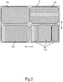
- Fig.2 shows in frontal view another possible carrier 12, which is used for example in place of the carrier 2 in the lighting device 1.
- the carrier 12 has four fluorescent surfaces 13a, 13b, 13c and 13d arranged next to one another in a 2x2 matrix pattern. Only one phosphor surface 13a, 13b, 13c or 13d is illuminated in each case. Each individual phosphor surface 13a, 13b, 13c or 13d can consequently produce a complete light emission pattern L.
- a linear movement of the carrier 12 in its plane (for example, generated by means of the linear motor 10), it can be moved so that each of the phosphor surfaces 13a, 13b, 13c or 13d can be brought into the illumination surface 7 respectively.
- the linear movement is indicated by the double-sided arrows.
- n and m are integers, at least one of which is greater than one.
- a length-to-width ratio or aspect ratio of the individual phosphor surfaces is arbitrary.
- the individual phosphor surfaces need not be rectangular, but may take other forms. Between the phosphor surfaces, there may also be areas that are free of phosphor. Also, an irregular arrangement of the phosphor surfaces is possible. Likewise, the arrangement of the phosphors within a phosphor surface is not limited. Any desired division can be used. Realizations are possible both in a transmissive use (transmitted light arrangement as shown) and in a reflective use of the phosphor.
- the reflectors 6a and 6b in turn are illuminated by the phosphor surfaces 3a, 3b or 3c or 3d, 3e or 3f.
- a light emission pattern L in the far field F can then be composed by a superimposition of the useful light emitted by both reflectors 6a and 6b (not shown). This corresponds to an addition of the useful light generated by opposing phosphor surfaces 3a and 3d, 3b and 3e or 3f and 3c.
- a specific Lichtabstrahlstrahlmuster can be adjusted for example by any, but then firmly selected combination of the phosphor surfaces A1 to A3, B1 to B3, C1 to C3 and D1 to D3.
- the light generated in this process can again be thrown into the far field F by means of optics (not shown), in particular an imaging optic.
- respective linear motors 10a to 10d may be used, which are controllable together by the control device 11.
- the control device 11 can also receive control commands ST for controlling the linear motors 10a to 10d, which predetermine the light emission pattern L to be generated.
- These Control commands ST are converted by the control device 11 into drive signals for the linear motors 10a to 10d in order to bring the combination of the phosphor areas A1 to D3, corresponding to the desired light emission pattern, into the illumination area 32.
- a number may include exactly the specified number as well as a usual tolerance range, as long as this is not explicitly excluded.
Description
Die Erfindung betrifft eine Leuchtvorrichtung für einen Scheinwerfer zum Erzeugen eines Lichtabstrahlmusters in einem Fernfeld, aufweisend mindestens eine Leuchtstofffläche und mindestens eine von der Leuchtstofffläche beabstandete Lichtquelle zur Aussendung von Primärlicht zur Beleuchtung der Leuchtstofffläche, wodurch ein zugehöriges Lichtabstrahlmuster erzeugbar ist. Die Erfindung ist insbesondere anwendbar auf einen Fahrzeugscheinwerfer, insbesondere für einen Personen- oder Lastkraftwagen.The invention relates to a lighting device for a headlight for generating a Lichtabstrahlmusters in a far field, comprising at least one phosphor surface and at least one spaced from the phosphor surface light source for emitting primary light for illuminating the phosphor surface, whereby an associated Lichtabstrahlmuster can be generated. The invention is particularly applicable to a vehicle headlamp, especially for a passenger or truck.
Die
Es ist die Aufgabe der vorliegenden Erfindung, die Nachteile des Standes der Technik zumindest teilweise zu überwinden und insbesondere eine verbesserte Möglichkeit zur vielgestaltigen Einstellung eines Lichtabstrahlmusters mittels einer "Remote-Phosphor"-Vorrichtung bereitzustellen.
The
It is the object of the present invention to at least partially overcome the disadvantages of the prior art, and in particular to provide an improved possibility for the multi-faceted adjustment of a Lichtabstrahlmusters means of a "remote phosphor" device.
Diese Aufgabe wird gemäß den Merkmalen des unabhängigen Anspruchs gelöst. Bevorzugte Ausführungsformen sind insbesondere den abhängigen Ansprüchen entnehmbar.This object is solved according to the features of the independent claim. Preferred embodiments are in particular the dependent claims.
Diese Leuchtvorrichtung weist den Vorteil auf, dass mit einem vergleichsweise geringen konstruktiven Aufwand zwischen verschiedenen Lichtabstrahlmustern umgeschaltet werden kann.This lighting device has the advantage that it can be switched with a comparatively small design effort between different Lichtabstrahlmustern.
Dass die Leuchtstoffflächen in die Beleuchtungsfläche einbringbar sind, umfasst, dass die Leuchtstoffflächen von der mindestens einen Lichtquelle beabstandet angeordnet sind. Dies entspricht einer "Remote-Phosphor"-Anordnung.The fact that the fluorescent surfaces can be introduced into the illumination surface comprises that the fluorescent surfaces are arranged at a distance from the at least one light source. This corresponds to a "remote phosphor" arrangement.
Das Fernfeld mag insbesondere ein Feld oder Raum in einem Abstand von mindestens zwei Metern bis zu einem Abstand von mehreren Hundert Metern vor dem Scheinwerfer sein.In particular, the far field may be a field or space at a distance of at least two meters to a distance of several hundred meters in front of the headlight.
Die Beleuchtungsfläche mag insbesondere in der Größe und Ausdehnung und Formfaktor einem durch das Primärlicht erzeugten Leuchtfleck entsprechen.The illumination surface may correspond in particular in size and extent and shape factor to a light spot generated by the primary light.
Eine Leuchtstofffläche weist mindestens einen Leuchtstoff oder Konversions(farb)stoff auf, welcher das darauf einfallende Primärlicht zumindest teilweise in Sekundärlicht unterschiedlicher Wellenlänge, insbesondere größerer Wellenlänge, umwandelt oder konvertiert. Diese Wellenlängenkonversion ist grundsätzlich bekannt und braucht hier nicht weiter ausgeführt zu werden. Beispielsweise mag ein Leuchtstoff einfallendes blaues Primärlicht teilweise in gelbes Sekundärlicht umwandeln, so dass von der Leuchtstofffläche insgesamt blau-gelbes bzw. weißes Mischlicht mit entsprechenden Anteilen aus Primärlicht und Sekundärlicht abgestrahlt wird. Grundsätzlich ist jedoch auch eine Vollkonversion möglich.A phosphor surface has at least one phosphor or conversion (color) substance which at least partially converts or converts the primary light incident thereon into secondary light of different wavelength, in particular of a larger wavelength. This wavelength conversion is basically known and need not be further elaborated here. For example, a phosphor may partially convert incident blue primary light into yellow secondary light, so that a total of blue-yellow or white mixed light with corresponding proportions of primary light and secondary light is radiated from the phosphor surface. In principle, however, a full conversion is possible.
Dass Leuchtstoffflächen unterschiedlich sind, mag insbesondere umfassen, dass sie eine unterschiedliche Form, eine unterschiedliche Art von Leuchtstoff(en) und/oder eine unterschiedliche Leuchtstoffverteilung aufweisen. Die unterschiedliche Leuchtstoffverteilung mag eine unterschiedliche Konzentration des Leuchtstoffs und/oder eine unterschiedliche Dicke der Leuchtstofffläche umfassen. Die unterschiedliche Art von Leuchtstoff mag vollständig unterschiedliche Leuchtstoffe (z.B. Leuchtstoff A in einer Leuchtstofffläche und Leuchtstoff B in einer anderen Leuchtstofffläche) oder teilweise unterschiedliche Leuchtstoffe (z.B. Leuchtstoff A in einer Leuchtstofffläche und Leuchtstoffe A und B in einer anderen Leuchtstofffläche) umfassen. Unterschiedliche Leuchtstoffflächen bewirken bei ihrer Bestrahlung mit Primärlicht entsprechend unterschiedliche Lichtabstrahlmuster. So mag für eine Erzeugung eines Lichtabstrahlmusters mit inhomogener Farbverteilung mindestens eine zugehörige Leuchtstofffläche inhomogen mit mindestens einem Leuchtstoff belegt sein, z.B. mit einer inhomogenen Schichtdicke und/oder einer inhomogenen Leuchtstoffkonzentration mindestens eines Leuchtstoffs, insbesondere großflächig. Durch die Änderung einer Lichtfarbe des Lichtabstrahlmusters mittels einer unterschiedlichen Leuchtstoffverteilung zweier abwechselnd beleuchtbarer Leuchtstoffflächen lassen sich wiederum bestimmte Randbedingungen des Fahrzeugs und/oder des Fahrers besser berücksichtigen. So lässt sich die Lichtfarbe zum Beispiel an ein Vorliegen von Nebel oder Regen, aber z.B. auch an eine Kombination von Nebel oder Regen mit einem alten oder einem jungen Fahrer anpassen. Auch die Eigenheiten von Farbblinden oder Teilfarbblinden (z.B. mit einer rot/grün-Schwäche) können nun berücksichtigt werden. Dadurch wiederum lässt sich eine größere Verkehrssicherheit erreichen. Es kann auch zusätzlicher Komfort für den Fahrer bzw. die Insassen erzeugt werden.That phosphor surfaces are different may include, in particular, that they have a different shape, a different type of phosphor (s) and / or a different phosphor distribution. The different phosphor distribution may include a different concentration of the phosphor and / or a different thickness of the phosphor surface. The Different types of phosphor may include completely different phosphors (eg phosphor A in one phosphor surface and phosphor B in another phosphor surface) or partially different phosphors (eg phosphor A in one phosphor surface and phosphors A and B in another phosphor surface). Different fluorescent surfaces cause correspondingly different light emission patterns when irradiated with primary light. Thus, to generate a light emission pattern with inhomogeneous color distribution, at least one associated phosphor surface may be inhomogeneously coated with at least one phosphor, eg with an inhomogeneous layer thickness and / or an inhomogeneous phosphor concentration of at least one phosphor, in particular over a large area. By changing a light color of the light emission pattern by means of a different phosphor distribution of two alternately illuminable phosphor surfaces, in turn, certain boundary conditions of the vehicle and / or the driver can be better taken into account. For example, the light color can be adapted to the presence of fog or rain, but also, for example, to a combination of fog or rain with an old or a young driver. Also, the peculiarities of color blind or partially color blind (eg with a red / green weakness) can now be considered. This, in turn, can achieve greater traffic safety. It may also be additional comfort for the driver or passengers are generated.
Mindestens eine Leuchtstofffläche mag eine gleichförmige Verteilung von Leuchtstoff aufweisen. Dies ermöglicht ein gleichförmig ausleuchtendes Lichtabstrahlmuster.At least one phosphor surface may have a uniform distribution of phosphor. This enables a uniformly illuminating light emission pattern.
Zusätzlich oder alternativ mag mindestens eine Leuchtstofffläche eine ungleichförmige Verteilung mindestens eines Leuchtstoffs aufweisen. Dies ermöglicht auf besonders einfache Weise ein z.B. in Bezug auf eine Helligkeit und/oder eine Lichtfarbe vielgestaltiges Lichtabstrahlmuster. Insbesondere mag mindestens eine Leuchtstofffläche mehrere Leuchtstoffe aufweisen, welche zueinander ungleichmäßig über die Leuchtstofffläche verteilt sind. Dadurch lassen sich auf besonders einfache Weise mehrfarbige Lichtabstrahlmuster bereitstellen. Weist ein Teilbereich der Farbstofffläche Teilbereiche auf, in denen mehrere Leuchtstoffe vorhanden sind, lässt sich einfach ein Lichtabstrahlmuster mit farblich ineinander übergehenden Teilbereichen erzeugen. Jedoch mag eine Leuchtstofffläche auch voneinander getrennte Teilbereiche mit unterschiedlichen Leuchtstoffkonzentrationen und/oder Leuchtstoffen oder Leuchtstoffmischungen aufweisen. Ergänzend oder alternativ mögen die Teilbereiche mit unterschiedlichen Leuchtstoffkonzentrationen aneinander angrenzen und zumindest einen Teilbereich der Beleuchtungsfläche zusammenhängend ausfüllen. Dazu sind beispielsweise Teilbereiche mit einer sechszählig-polygonalen Struktur und/oder als Kombination von verschiedenen geometrischen Formen vorgesehen, und zwar insbesondere im Sinne einer lückenlosen "Tesselation" (z.B. einer sog. "Penrose-Tesselation").Additionally or alternatively, at least one phosphor surface may have a non-uniform distribution of at least one phosphor. This allows in a particularly simple manner, for example, in terms of brightness and / or a light color multi-shaped Lichtabstrahlmuster. In particular, at least one phosphor surface may comprise a plurality of phosphors which are distributed unevenly over the phosphor surface. As a result, multi-colored light emission patterns can be provided in a particularly simple manner. If a partial region of the dye surface has partial regions in which a plurality of phosphors are present, it is easy to produce a light emission pattern with subregions that merge into one another. However, a phosphor surface may also have separate subregions with different phosphor concentrations and / or phosphors or phosphor mixtures. Additionally or alternatively, the subregions with different phosphor concentrations may adjoin one another and fill at least one subarea of the illumination surface in a coherent manner. For this purpose, for example, partial areas with a hexagonal-polygonal structure and / or as a combination of different geometric shapes are provided, in particular in the sense of a complete "tesselation" (eg a so-called "Penrose tesselation").
Die mehreren Leuchtstoffflächen sind auf mehreren translatorisch verschiebbaren Trägern angeordnet. Dies ergibt den Vorteil, dass eine Position der Leuchtstoffflächen auf eine mechanisch einfache Weise, nämlich mittels einer Verschiebung des mindestens einen Trägers, veränderbar ist. Insbesondere mag eine bestimmte translatorische Position des Trägers einem zugehörigen Lichtabstrahlmuster entsprechen.
Die Leuchtstoffflächen mögen beispielsweise schichtartig bzw. als Schicht oder Schichtsystem auf dem Träger angeordnet sein. Der Träger mag eine platten- oder scheibenartige Grundform aufweisen. Der Träger besteht für eine effektive Wärmeabfuhr von dem Leuchtstoff vorzugsweise aus einem gut leitenden Material, z.B. aus Metall oder Saphir. Der Träger mag gekühlt sein.The plurality of phosphor surfaces are arranged on a plurality of translationally displaceable carriers. This results in the advantage that a position of the phosphor surfaces in a mechanically simple manner, namely by means of a displacement of the at least one carrier, is variable. In particular, a particular translational position of the carrier may correspond to an associated Lichtabstrahlmuster.
The phosphor surfaces may, for example, be arranged in layers or as a layer or layer system on the carrier. The carrier may have a plate-like or disc-like basic shape. The carrier preferably consists of a highly conductive material, for example of metal or sapphire, for effective heat removal from the phosphor. The wearer may be cooled.
Es ist eine Weiterbildung, dass von jeder Leuchtstofffläche, weißes oder weißliches Licht, insbesondere durch nur teilweise Konversion erzeugtes Mischlicht, abgestrahlt werden kann. Dadurch können insbesondere Leuchtstoffflächen ausgeschlossen werden, bei welchen das Mischlicht erst nach der Leuchtstofffläche durch Überlagerung erzeugt wird, z.B. indem von der Leuchtstofffläche erzeugte verschiedenfarbige Strahlung nach oder hinter der Leuchtstofffläche zusammenkommt. Beispielsweise können so Leuchtstoffflächen ausgeschlossen werden, welche eng nebeneinander angeordnete (eng lokalisierte) Bereiche mit unterschiedlichen Leuchtstoffen aufweisen (z.B. in Streifenform oder als Bildpunkte gruppiert), wobei die Leuchtstoffe Sekundärlicht mit jeweiligen Farbanteilen des Mischlichts erzeugen. Ausgeschlossen sein können daher insbesondere Streifen oder Bildpunkte mit Grundfarben erzeugenden Leuchtstoffen, z.B. den Grundfarben rot, grün und/oder blau (RGB-Farbraum) oder cyan, magenta und/oder gelb (CMY-Farbraum).It is a development that from each phosphor surface, white or whitish light, in particular by only partial conversion generated mixed light, can be emitted. As a result, in particular phosphor surfaces can be excluded in which the mixed light is generated only after the phosphor surface by superposition, e.g. in that different colored radiation generated by the phosphor surface comes together behind or behind the phosphor surface. For example, phosphor surfaces can be excluded so as to have closely juxtaposed (narrowly localized) regions with different phosphors (e.g., in stripe form or grouped as pixels), the phosphors producing secondary light with respective color fractions of the blend light. Therefore, in particular strips or pixels with primary color-producing phosphors, e.g. the primary colors red, green and / or blue (RGB color space) or cyan, magenta and / or yellow (CMY color space).
Eine Verwendung zweier Leuchtstoffe mit unterschiedlichen Farben des durch sie erzeugten Sekundärlichts ist jedoch grundsätzlich ebenso denkbar, z.B. für einen Wechsel zwischen einem Tagfahrlicht oder einem Standlicht mit weißer Farbe und einer Blinkerfunktion (z.B. für eine Richtungswechselanzeige) mit gelber Farbe.However, use of two phosphors with different colors of the secondary light generated by them is also conceivable in principle, e.g. for a change between a daytime running light or a parking light with white color and a turn signal function (for example for a direction change display) with yellow color.
Es ist eine Weiterbildung, dass das von der Leuchtstofffläche reflektierte oder zurückgestreute Licht als Nutzlicht zur Erzeugung des Lichtabstrahlmusters im Fernfeld verwendet wird ("reflektive Anordnung"). Dies mag insbesondere bedeuten, dass dieses Licht der Leuchtstofffläche gezielt reflektiert wird (z.B. durch Anbringung auf einem reflektiven Träger). Alternativ oder zusätzlich mag das an der dem einfallenden Primärlicht abgewandten Seite der Leuchtstofffläche austretende Licht als Nutzlicht zur Erzeugung eines Lichtabstrahlmusters im Fernfeld verwendet werden ("Durchlichtanordnung" oder "transmittive Anordnung").It is a further development that the light reflected or backscattered by the phosphor surface is used as useful light for generating the light emission pattern in the far field ("reflective arrangement"). This may mean in particular that this light of the phosphor surface is selectively reflected (eg by attachment to a reflective support). Alternatively or additionally, the light emerging at the side of the phosphor surface facing away from the incident primary light may be used as useful light for generating a light emission pattern in the far field ("transmitted light arrangement" or "transmissive arrangement").
Die mindestens eine Lichtquelle ist in ihrer Art grundsätzlich nicht beschränkt. Zur besonders effektiven Wellenlängenkonversion wird eine Lichtquelle mit einem schmalen Spektralband bevorzugt, wie beispielsweise Halbleiterlichtquellen, z.B. eine Leuchtdiode (LED) oder insbesondere eine Laserdiode. Es ist eine Weiterbildung, dass zumindest eine Lichtquelle eine Halbleiterlichtquelle ist. In einer Variante umfasst die mindestens eine Halbleiterlichtquelle mindestens eine Leuchtdiode. Die mindestens eine Leuchtdiode kann selbst mindestens einen wellenlängenumwandelnden Leuchtstoff enthalten (Konversions-LED). Die mindestens eine Leuchtdiode kann in Form mindestens einer gehausten Leuchtdiode oder in Form mindestens eines LED-Chips vorliegen. Mehrere LED-Chips können auf einem gemeinsamen Substrat ("Submount") montiert sein. Anstelle oder zusätzlich zu anorganischen Leuchtdioden, z.B. auf Basis von InGaN oder AlInGaP, sind allgemein auch organische LEDs (OLEDs, z.B. Polymer-OLEDs) einsetzbar. Alternativ kann die mindestens eine Halbleiterlichtquelle z.B. mindestens einen Diodenlaser aufweisen oder ein solcher sein. Die mindestens eine Halbleiterlichtquelle kann mit mindestens einer eigenen und/oder gemeinsamen Optik zur Strahlführung ausgerüstet sein, z.B. mindestens einer Fresnel-Linse, Kollimator, und so weiter.The at least one light source is basically not limited in its kind. For particularly effective wavelength conversion, a light source having a narrow spectral band is preferred, such as semiconductor light sources, e.g. a light emitting diode (LED) or in particular a laser diode. It is a development that at least one light source is a semiconductor light source. In one variant, the at least one semiconductor light source comprises at least one light-emitting diode. The at least one light-emitting diode may itself contain at least one wavelength-converting phosphor (conversion LED). The at least one light-emitting diode can be in the form of at least one light-emitting diode or in the form of at least one LED chip. Several LED chips can be mounted on a common substrate ("submount"). Instead of or in addition to inorganic light emitting diodes, e.g. based on InGaN or AlInGaP, organic LEDs (OLEDs, for example polymer OLEDs) can generally also be used. Alternatively, the at least one semiconductor light source may be e.g. have at least one diode laser or be such. The at least one semiconductor light source may be equipped with at least one own and / or common optics for beam guidance, e.g. at least one Fresnel lens, collimator, and so on.
Das von mindestens einer Lichtquelle erzeugte Primärlicht mag in zwei oder mehr unterschiedliche Lichtstrahlen aufgespalten werden, z.B. mittels eines Strahlteilers. Das Licht mehrerer Lichtquellen mag alternativ oder zusätzlich in einem Lichtstrahl kombiniert oder vereint werden.The primary light generated by at least one light source may be split into two or more different light beams, e.g. by means of a beam splitter. The light of several light sources may alternatively or additionally be combined or combined in a light beam.
Die Steuereinrichtung mag mit mindestens einem Motor zum Bewegen der Leuchtstoffflächen gekoppelt sein oder mag mindestens einen solchen Motor aufweisen. Der mindestens eine Motor mag insbesondere mindestens einen Träger für die Leuchtstoffflächen translatorisch, insbesondere linear, verschieben. Die Steuereinrichtung mag eine Elektronik sein. Die Steuereinrichtung mag ein Teil einer als Modul in das Fahrzeug einbaubaren Leuchtvorrichtung sein oder mag in dem Fahrzeug bereitgestellt sein und nach Einbau einer Leuchtvorrichtung damit verbunden werden, insbesondere mit einem Motor der Leuchtvorrichtung.The control device may be coupled to at least one motor for moving the phosphor surfaces or may have at least one such motor. The at least one motor may in particular translate at least one carrier for the phosphor surfaces translationally, in particular linearly. The control device may be electronics. The control device may be part of a lighting device which can be installed as a module in the vehicle or may be provided in the vehicle and connected thereto after installation of a lighting device, in particular with a motor of the lighting device.
Es ist eine Weiterbildung, dass zumindest zwei Leuchtstoffflächen voneinander beabstandet angeordnet sind, z.B. durch einen Spalt oder eine Kante oder eine Ecke getrennt. Es ist noch eine Weiterbildung, dass zumindest zwei Leuchtstoffflächen direkt aneinander angrenzend angeordnet sind, z.B. praktisch spaltfrei anliegend angeordnet sind oder als Teilbereiche einer durchgängig ausgebildeten größeren (Mehrfach- oder Gruppen-)Leuchtstofffläche ausgebildet sind.It is a development that at least two phosphor surfaces are arranged at a distance from each other, e.g. separated by a gap or an edge or a corner. It is still a further development that at least two phosphor surfaces are arranged directly adjacent to one another, e.g. arranged virtually gap-free adjacent or formed as subregions of a consistently formed larger (multiple or group) fluorescent surface.
Die Form einer Leuchtstofffläche ist nicht beschränkt und mag zumindest teilweise eben oder gekrümmt sein. Die Leuchtstofffläche mag frei geformt sein und z.B. mehrere Facetten aufweisen. Auch mögen Leuchtstoffflächen aus der Grundebene herausragen, beispielsweise durch eine Verkippung oder Neigung.The shape of a phosphor surface is not limited and may be at least partially planar or curved. The phosphor surface may be freely shaped and e.g. have multiple facets. Also, fluorescent surfaces may protrude from the ground plane, for example by tilting or tilting.
Der Leuchtstofffläche mag eine dazu ortsfest angeordnete bzw. mitverschiebbare Optik vorgelagert sein, beispielsweise zur Strahlformung und/oder spektralen Filterung eines auf die Leuchtstofffläche einfallenden Lichtstrahls und/oder zur Strahlformung und/oder spektralen Filterung eines von der Leuchtstofffläche abgestrahlten Lichts (einschließlich eines Mischlichts). Die Optik mag ein oder mehrere optische Elemente aufweisen, z.B. mindestens eine Linse, mindestens einen Konzentrator, mindestens einen Kollimator, mindestens einen Reflektor, mindestens eine Blende, mindestens einen Filter usw.The phosphor surface may be preceded by a stationary or co-displaceable optics, for example for beam shaping and / or spectral filtering of a light beam incident on the phosphor surface and / or beam shaping and / or spectral filtering of a light emitted by the phosphor surface (including a mixed light). The optics may have one or more optical elements, e.g. at least one lens, at least one concentrator, at least one collimator, at least one reflector, at least one aperture, at least one filter, etc.
Es ist auch eine Weiterbildung, dass mindestens einer aktuell beleuchtbaren Leuchtstofffläche (die sich also innerhalb der Beleuchtungsfläche befindet) eine Optik zum Richten des von der mindestens einen Leuchtstofffläche abgestrahlten Lichts in das Fernfeld nachgeschaltet ist. Diese nachgeschaltete ("sekundäre") Optik ist insbesondere nicht mit den Leuchtstoffflächen zusammen drehbeweglich und dient beispielsweise zur Strahlformung und/oder spektralen Filterung des von der Leuchtstofffläche abgestrahlten Lichts (einschließlich eines Mischlichts). Die Optik mag ein oder mehrere optische Elemente aufweisen, z.B. mindestens eine Linse, Konzentrator, Kollimator, Reflektor, Blende, Filter usw. Bei einer Beleuchtung mehrerer Leuchtstoffflächen mögen diese gleiche und/oder unterschiedliche Bereiche der nachgeschalteten Optik anstrahlen.It is also a further development that at least one currently illuminable phosphor surface (which is thus located within the illumination surface) has optics for directing the light emitted by the at least one phosphor surface is connected downstream of the far field. This downstream ("secondary") optic is in particular not rotatable together with the phosphor surfaces and serves, for example, for beam shaping and / or spectral filtering of the light emitted by the phosphor surface (including a mixed light). The optics may have one or more optical elements, for example at least one lens, concentrator, collimator, reflector, aperture, filter, etc. If a plurality of phosphor surfaces illuminate, they may illuminate the same and / or different regions of the downstream optics.
Es ist ferner eine Weiterbildung, dass die Leuchtvorrichtung mindestens einen schalenartigen Reflektor aufweist, welcher mindestens einer aktuell beleuchtbaren Leuchtstofffläche nachgeschaltet ist. Die mindestens eine aktuell beleuchtbare Leuchtstofffläche befindet sich bevorzugt im Bereich eines Brennflecks des davon angestrahlten Reflektors.It is also a development that the lighting device has at least one shell-like reflector, which is connected downstream of at least one currently illuminated phosphor surface. The at least one currently illuminable phosphor surface is preferably located in the region of a focal spot of the reflector illuminated by it.
Insbesondere mögen mindestens zwei Lichtabstrahlmuster eine unterschiedlich weiße Lichtfarbe aufweisen. Es ist eine Weiterbildung davon, dass sie eine gleiche Form aufweisen. So mag ein Lichtabstrahlmuster nur farblich geändert werden, z.B. zur Anpassung an geänderte Lichtverhältnisse.In particular, at least two light emission patterns may have a different white light color. It is a development that they have the same shape. Thus, a light-emitting pattern may only be changed in color, e.g. to adapt to changed lighting conditions.
Auch ist es möglich, zwei disjunkte (sich nicht überlappende) Teilbereiche einer Leuchtstofffläche mit unterschiedlichen Leuchtstoffen jeweils homogen zu versehen.It is also possible to provide two disjoint (non-overlapping) portions of a phosphor surface with different phosphors each homogeneous.
Es ist eine Ausgestaltung, dass mindestens eine Leuchtstofffläche mittels einer reinen Translationsbewegung (also ohne einen Rotationsanteil) in die Beleuchtungsfläche bewegbar ist. Die mindestens eine Leuchtstofffläche behält also ihre Ausrichtung im Raum bei. So lässt sich eine besonders einfache Bewegung erreichen.It is an embodiment that at least one phosphor surface can be moved into the illumination surface by means of a pure translational movement (that is to say without a rotational component). The at least one phosphor surface thus retains its orientation in space. This makes it possible to achieve a particularly simple movement.
Eine Bewegungsbahn oder Trajektorie der mindestens einen Leuchtstofffläche ist grundsätzlich beliebig und mag also auch gekrümmt sein. Die Bewegungsbahn mag in einem dreidimensionalen Raum oder in einer Ebene liegen. Für eine besonders einfache Bewegung mag die Translationsbewegung eine lineare oder geradlinige Translationsbewegung sein.A trajectory or trajectory of the at least one phosphor surface is basically arbitrary and therefore may also be curved. The trajectory may be in a three-dimensional space or in a plane. For a particularly simple movement, the translation movement may be a linear or rectilinear translational movement.
Zudem mag der Translationsbewegung eine Rotationsbewegung der mindestens einen Leuchtstofffläche überlagert sein, insbesondere um eine Verschwenkung der Leuchtstofffläche zu erreichen. Auch mag anstelle oder zusätzlich zu einer linearen Translationsbewegung eine auf einer gekrümmten Trajektorie oder Bewegungsbahn verschobene mindestens eine Leuchtstofffläche verwendet werden.In addition, the translational movement may be superimposed by a rotational movement of the at least one phosphor surface, in particular in order to achieve a pivoting of the phosphor surface. Also, instead of or in addition to a linear translational movement, at least one phosphor surface displaced on a curved trajectory or trajectory may be used.
Es ist noch eine Ausgestaltung, dass mindestens eine Leuchtstofffläche mittels einer Translationsbewegung und zusätzlich einer Rotationsbewegung in die Beleuchtungsfläche bewegbar ist. Dies umfasst auch eine Schwenkbewegung der mindestens einen Leuchtstofffläche. Die Rotationsbewegung mag einen Drehpunkt oder eine Drehachse innerhalb der mindestens einen Leuchtstofffläche, innerhalb eines Trägers der Leuchtstofffläche oder beabstandet davon aufweisen.It is still an embodiment that at least one phosphor surface is movable by means of a translational movement and additionally a rotational movement in the illumination surface. This also includes a pivoting movement of the at least one phosphor surface. The rotational movement may include a fulcrum or a rotation axis within the at least one phosphor surface, within a carrier of the phosphor surface, or spaced therefrom.
Jedoch sind Leuchtvorrichtungen ausgeschlossen, bei denen sich eine Bewegung der mindestens einen Leuchtstofffläche, insbesondere aller Leuchtstoffflächen, rein durch eine Rotation beschreiben lässt, insbesondere um einen zu der Leuchtvorrichtung festen bzw. raumfesten Drehpunkt oder um eine raumfeste Drehachse beschreiben lässt.However, lighting devices are excluded in which a movement of the at least one phosphor surface, in particular of all phosphor surfaces, can be described purely by rotation, in particular by a solid or fixed to the light fulcrum or to describe a space fixed axis of rotation.
Es ist noch eine Ausgestaltung, dass ein Lichtabstrahlmuster mittels mindestens eines stationär ausgerichteten Primärlichtstrahls (also "statisch") erzeugbar ist. Dies bedeutet insbesondere, dass sich ein Lichtpfad mindestens eines Primärlichtstrahls nicht zeitlich ändert, sondern stationär bzw. fest ausgerichtet bleibt. Das Lichtabstrahlmuster wird dabei insbesondere zu jedem Zeitpunkt vollständig erzeugt. Diese Ausgestaltung ist besonders einfach umsetzbar.It is still an embodiment that a Lichtabstrahlmuster by means of at least one stationary aligned primary light beam (ie "static") can be generated. This means in particular that a light path of at least one primary light beam does not change with time, but remains stationary or fixed. The Lichtabstrahlmuster is generated completely in particular at any time. This embodiment is particularly easy to implement.
Es ist eine speziell für diese Ausgestaltung bevorzugte Weiterbildung, dass der mindestens eine Primärlichtstrahl eine signifikante Querschnittsgröße aufweist. Dadurch ergibt sich der Vorteil, dass der Primärlichtstrahl einen großen Bereich der aktuell in der bestimmten befindlichen Position beleuchtbaren mindestens einen Leuchtstofffläche gleichzeitig beleuchten kann.It is a development that is particularly preferred for this embodiment that the at least one primary light beam has a significant cross-sectional size. This results in the advantage that the primary light beam can simultaneously illuminate a large area of the at least one phosphor surface which can currently be illuminated in the determined position.
Es ist auch noch eine Ausgestaltung, dass ein Lichtabstrahlmuster mittels einer Bewegung mindestens eines Primärlichtstrahls (also "dynamisch") erzeugbar ist. Dies ermöglicht eine - insbesondere zeilenweise - abrasternde oder "scannende" Beleuchtung der Leuchtstofffläche, bei welcher mindestens ein Primärlichtstrahl verschiedene Bereiche der mindestens einen Leuchtstofffläche nacheinander beleuchtet. Dadurch können unterschiedlich geformte Lichtabstrahlmuster mittels einer sich in einer gleichen Position befindlichen gleichen Leuchtstofffläche erzeugt werden. Es ist auch möglich, die Bewegung des Primärlichtstrahls nicht-resonant durchzuführen, also nicht periodisch Zeilen und Spalten zu beschreiben, sondern die Bewegung des Primärlichtstrahls völlig frei zu handhaben.It is also an embodiment that a Lichtabstrahlmuster by means of a movement of at least one primary light beam (ie "dynamic") can be generated. This makes possible - in particular line by line - scanning or "scanning" illumination of the phosphor surface, in which at least one primary light beam successively illuminates different regions of the at least one phosphor surface. As a result, differently shaped light emission patterns can be generated by means of a same phosphor surface located in the same position. It is also possible to perform the movement of the primary light beam non-resonant, so not periodically to describe lines and columns, but to handle the movement of the primary light beam completely free.
Es ist eine weitere Ausgestaltung, dass mehrere (d.h., mindestens zwei) Leuchtstoffflächen auf mindestens einem gemeinsamen, translatorisch, insbesondere linear, verschiebbaren oder beweglichen Träger angeordnet sind. Dies ergibt den Vorteil, dass eine Position aller Leuchtstoffflächen des gemeinsamen Trägers auf eine mechanisch einfache Weise, nämlich mittels einer Verschiebung dieses Trägers, veränderbar ist. Insbesondere mag eine bestimmte translatorisch, insbesondere lineare, Position des Trägers einem zugehörigen Lichtabstrahlmuster entsprechen. Diese Ausgestaltung umfasst, dass alle Leuchtstoffflächen auf genau einem gemeinsamen Träger angeordnet sind. Diese Ausgestaltung umfasst auch, dass die Leuchtstoffflächen auf mehreren Trägern angeordnet sind, wobei an mindestens einem Träger, insbesondere an mehreren Trägern, jeweils mindestens zwei Leuchtstoffflächen angeordnet sind.It is a further embodiment that a plurality (ie, at least two) phosphor surfaces are arranged on at least one common, translational, in particular linear, displaceable or movable carrier. This results in the advantage that a position of all phosphor surfaces of the common carrier in a mechanically simple manner, namely by means of a displacement of this carrier, is changeable. In particular, a particular translational, in particular linear, position of the carrier may correspond to an associated light emission pattern. This embodiment comprises that all the phosphor surfaces are arranged on exactly one common carrier. This embodiment also includes that the phosphor surfaces are arranged on a plurality of carriers, wherein at least one Carrier, in particular on a plurality of carriers, in each case at least two phosphor surfaces are arranged.
Es ist noch eine weitere Ausgestaltung, dass der mindestens eine translatorisch, insbesondere linear, verschiebbare Träger mehrere unabhängig voneinander translatorisch, insbesondere linear, verschiebbare Träger mit jeweils mehreren Leuchtstoffflächen aufweist, wobei in die Beleuchtungsfläche gleichzeitig jeweils eine Leuchtstofffläche eines jeweiligen Trägers einbringbar ist. Das Lichtabstrahlmuster der Leuchtvorrichtung ist folglich mittels einer Addition der einzelnen Lichtabstrahlmuster der in der Beleuchtungsfläche befindlichen Leuchtstoffflächen der einzelnen Träger erzeugbar. Eine Änderung des Lichtabstrahlmusters lässt sich durch eine Verschiebung eines oder mehrerer dieser Träger und damit einer Auswechselung mindestens einer Leuchtstofffläche in der Beleuchtungsfläche erreichen. Diese Ausgestaltung ermöglicht auf einfache Weise eine besonders vielfältige Ausgestaltung des Lichtabstrahlmusters. Dadurch lässt sich ein Lichtabstrahlmuster auf besonders kompakte Weise erzeugen.It is yet a further embodiment that the at least one translationally, in particular linear, displaceable carrier has a plurality of translucent, in particular linear, displaceable carrier, each having a plurality of phosphor surfaces, wherein in the illumination surface in each case a respective fluorescent surface of a respective carrier can be introduced. Consequently, the light emission pattern of the lighting device can be generated by adding the individual light emission patterns of the phosphor surfaces of the individual substrates located in the illumination surface. A change in the Lichtabstrahlmusters can be achieved by a shift of one or more of these carriers and thus a replacement of at least one phosphor surface in the illumination surface. This embodiment enables in a simple manner a particularly diverse embodiment of the Lichtabstrahlmusters. This allows a Lichtabstrahlmuster produce in a particularly compact manner.
Die Träger mögen insbesondere parallel zueinander verschiebbare Träger sein. Die Träger mögen die gleiche Grundform aufweisen, z.B. eine streifenartige Grundform. Die Träger mögen in einer Reihe benachbart zueinander angeordnet sein, insbesondere kollinear.The carriers may in particular be mutually displaceable carriers. The supports may have the same basic shape, e.g. a strip-like basic shape. The carriers may be arranged in a row adjacent to each other, in particular collinear.
Die gleichzeitige Beleuchtung der Leuchtstoffflächen mehrerer Träger lässt sich beispielsweise mittels eines oder mehrerer Primärlichtstrahlen umsetzen. Die mehreren Primärlichtstrahlen mögen z.B. von mindestens einer jeweiligen Lichtquelle erzeugt werden, alternativ mittels einer gemeinsamen Lichtquelle und folgender Aufspaltung des Primärlichtstrahls in mehrere Teilstrahlen.The simultaneous illumination of the phosphor surfaces of a plurality of carriers can be implemented, for example, by means of one or more primary light beams. The plural primary light beams may be e.g. be generated by at least one respective light source, alternatively by means of a common light source and subsequent splitting of the primary light beam into a plurality of partial beams.
Ganz allgemein mag das Lichtabstrahlmuster mittels einer gleichzeitigen Beleuchtung mehrerer individuell translatorisch, insbesondere linear, beweglicher Leuchtstoffflächen erzeugbar sein.In general, the light emission pattern may be individualized by simultaneous illumination of several be translatable, in particular linear, movable phosphor surfaces to be generated.
Der Scheinwerfer mag insbesondere ein Fahrzeugscheinwerfer sein. Das Fahrzeug mag ein Luftfahrzeug, ein wassergebundenes Fahrzeug oder ein landgebundenes Fahrzeug sein. Das landgebundene Fahrzeug mag ein Kraftfahrzeug sein. Besonders bevorzugt ist die Verwendung des Fahrzeugscheinwerfers in einem Lastkraftwagen oder Personenkraftwagen. Durch unterschiedliche Positionen der mindestens einen Leuchtstofffläche lassen sich unterschiedliche automobile Lichtabstrahlmuster erzeugen, z.B. zur Erzeugung eines Abblendlichts, eines Fernlichts, eines Nebellichts usw. Alternativ oder zusätzlich lassen sich gleich geformte Lichtabstrahlmuster mit unterschiedlicher Lichtfarbe bereitstellen, z.B. ein bläulicheres Tagfahrlicht und ein weniger "blaues" Positionslicht für nächtlichen Einsatz.The headlight may in particular be a vehicle headlight. The vehicle may be an aircraft, a waterborne vehicle, or a land vehicle. The land-based vehicle may be a motor vehicle. Particularly preferred is the use of the vehicle headlight in a truck or passenger car. Different positions of the at least one phosphor surface can be used to generate different automobile light emission patterns, e.g. for producing a low beam, a high beam, a fog light, etc. Alternatively or additionally, uniformly shaped light emitting patterns with different light color can be provided, e.g. a bluish daytime running light and a less "blue" position light for nocturnal use.
Besonders bevorzugt ist eine Ausgestaltung der Leuchtvorrichtung als Fahrzeugscheinwerfer oder als ein Teil davon, wobei der Fahrzeugscheinwerfer als ein AFS ("Adaptive Frontlighting System")- oder ein ADB ("Adaptive Driving Beam")-Scheinwerfer eingerichtet ist. Durch eine Änderung der Position mindestens einer Leuchtfläche ist eine einfache umsetzbare Änderung des Lichtabstrahlmusters (z.B. der Lichtfarbe oder Farbverteilung) als Reaktion auf äußere Einflüsse möglich. Solche Einflüsse können umgebungsbedingte Parameter, wie eine Wettersituation, ein Zustand einer Fahrbahn, eine Tageszeit, ein Sonnenstand usw. oder fahrerspezifische Parameter, wie Alter, Müdigkeit, Erfahrungsgrad usw. umfassen. Solche Parameter können durch eine entsprechend geartete Sensorik des Fahrzeugs z.B. eine Kamera, einen Regensensor, einen Abstandssensor usw. erfasst werden. Es ist so insbesondere auch möglich, im Rahmen eines AFS- oder ADB-Systems bestimmte Kombinationen von Parametern in der Lichtverteilung automatisch (insbesondere ohne Fahrermitwirkung) abzudecken. Also nicht nur die Anpassung der Farbe an zum Beispiel ein Vorliegen von Nebel, sondern auch an die Kombination von Nebel mit einem alten oder einem jungen Fahrer. Auch die Eigenheiten von Farbblinden oder Teilfarbblinden (z.B. mit einer rot/grün-Schwäche) können so berücksichtigt werden. Dadurch wiederum lässt sich eine größere Verkehrssicherheit erreichen. Es kann auch zusätzlicher Komfort für den Fahrer bzw. die Insassen erzeugt werden.Particularly preferred is an embodiment of the lighting device as a vehicle headlight or as a part thereof, wherein the vehicle headlight as an AFS ("Adaptive Frontlighting System") - or an ADB ("Adaptive Driving Beam") - headlights is set up. By changing the position of at least one luminous surface, a simple actionable change of the light emission pattern (eg the light color or color distribution) in response to external influences is possible. Such influences may include environmental parameters, such as a weather situation, a condition of a lane, a time of day, a position of the sun, etc., or driver-specific parameters such as age, fatigue, level of experience, and so on. Such parameters can be detected by a corresponding type of sensor of the vehicle, for example, a camera, a rain sensor, a distance sensor, etc. In particular, it is also possible within the framework of an AFS or ADB system to cover certain combinations of parameters in the light distribution automatically (in particular without driver involvement). So not just adjusting the color to, for example, the presence of fog, but also to the combination of fog with an old or a young driver. Also, the peculiarities of color blind or partially color blind (eg, with a red / green weakness) can be considered. This, in turn, can achieve greater traffic safety. It may also be additional comfort for the driver or passengers are generated.
Die oben beschriebenen Eigenschaften, Merkmale und Vorteile dieser Erfindung sowie die Art und Weise, wie diese erreicht werden, werden klarer und deutlicher verständlich im Zusammenhang mit der folgenden schematischen Beschreibung von Ausführungsbeispielen, die im Zusammenhang mit den Zeichnungen näher erläutert werden. Dabei können zur Übersichtlichkeit gleiche oder gleichwirkende Elemente mit gleichen Bezugszeichen versehen sein.
- Fig.1
- zeigt als Schnittdarstellung in Seitenansicht eine Leuchtvorrichtung gemäß einem ersten Ausführungsbeispiel mit einem linear verschieblichen Träger;
- Fig.2
- zeigt in Draufsicht einen linear verschieblichen Träger mit mehreren Leuchtstoffflächen;
- Fig.3
- zeigt als Schnittdarstellung in Seitenansicht eine Leuchtvorrichtung gemäß einem zweiten Ausführungsbeispiel; und
- Fig.4
- zeigt als Schnittdarstellung in Seitenansicht eine Leuchtvorrichtung gemäß einem dritten Ausführungsbeispiel.
- Fig.1
- shows a sectional side view of a lighting device according to a first embodiment with a linearly displaceable carrier;
- Fig.2
- shows in plan view a linearly displaceable carrier with a plurality of phosphor surfaces;
- Figure 3
- shows a sectional side view of a lighting device according to a second embodiment; and
- Figure 4
- shows a sectional side view of a lighting device according to a third embodiment.
Die Leuchtvorrichtung 1 weist einen platten- oder scheibenartigen Träger 2 für drei flächenartige Leuchtstoffvolumina auf, die im Folgenden als Leuchtstoffflächen 3a bis 3c bezeichnet werden. Die Leuchtstoffflächen 3a, 3b und 3c liegen nebeneinander in einer Reihe auf einer ebenen Oberfläche des Trägers 2 auf. Die Leuchtstoffflächen 3a bis 3c mögen z.B. auf den Träger 2 aufgesprüht oder aufgedruckt worden sein. Alternativ mögen die Leuchtstoffflächen 3a bis 3c als jeweils vorgefertigte Plättchen (z.B. Keramikplättchen) auf den Träger 2 aufgebracht worden sein, z.B. aufgeklebt worden sein.The
Die Leuchtvorrichtung 1 weist ferner eine Lichtquelle in Form eines Lasers 4 auf, welcher z.B. blaues Primärlicht P abstrahlt. Das blaue Primärlicht P weist bevorzugt, aber nicht notwendigerweise, eine Spitzenwellenlänge im Wellenlängenbereich von 360 nm bis 480 nm, insbesondere von 400 nm bis 460 nm, auf. Der Laser 4 mag z.B. eine oder mehrere Laserdioden aufweisen. Das Primärlicht P wird durch ein kleines Fenster 5 in einem schalenförmigen Reflektor 6 schräg auf den Träger 2 gestrahlt und kann dort eine Beleuchtungsfläche 7 erzeugen, die dem Leuchtfleck entspricht. Aufgrund des nur kleinen Fensters 5 und der schrägen Einstrahlung sind Lichtverluste durch eine Rückstrahlung in den Laser 4 gering.The
Der Strahlengang des Primärlichts P bleibt zeitlich unverändert, also stationär. Dadurch wird eine sich zeitlich nicht ändernde (statische) flächige Bereitstellung der Beleuchtungsfläche 7 erreicht.The beam path of the primary light P remains unchanged in time, ie stationary. As a result, a temporally non-changing (static) planar provision of the illumination surface 7 is achieved.
Zwischen dem Laser 4 und der Beleuchtungsfläche 7 ist eine hier durch eine Linse angedeutete Optik 8 zwischengeschaltet, z.B. zur Strahlkollimation. Auch mag das an der Beleuchtungsfläche 7 auftreffende Primärlicht P näherungsweise parallelisiert sein, anstatt wie angedeutet fokussiert zu werden. Falls ein fokussierender Strahlengang verwendet wird, ist es beispielsweise auch möglich, die Leuchtstoffflächen 3a bis 3c nicht in den Fokus des Strahls des Primärlichtstrahls P zu setzen (d.h. insbesondere auch nach dem Fokus bzw. im wieder divergierenden Strahl zu positionieren), um die Größe der Beleuchtungsfläche 7 einfacher einstellen zu können.Between the laser 4 and the illumination surface 7, an
Es ist eine Weiterbildung, dass sich der Laser 4 und die eventuelle vorhandene Optik 8 in einem gemeinsamen Gehäuse befinden und zusammen eine Einheit bilden. Es ist alternativ möglich, das Primärlicht P über eine Glasfaser zu dem Träger 2 bzw. zu dessen Leuchtstoffflächen 3a, 3b oder 3c zu führen.It is a development that the laser 4 and the possible existing
Der Träger 2 kann entlang seiner ausgedehnten Ebene durch eine translatorische Linearbewegung verschoben werden, hier entlang einer Verschiebungsrichtung V. Dabei nimmt der Träger 2 verschiedene Positionen ein, in denen jeweils eine der Leuchtstoffflächen 3a, 3b oder 3c in der Beleuchtungsfläche 7 liegt bzw. die Leuchtstoffflächen 3a bis 3c abwechselnd in die Beleuchtungsfläche 7 einbringbar sind. In noch anderen Worten kann der Träger 2 so linear verschoben werden, dass jeweils eine der Leuchtstoffflächen 3a, 3b oder 3c durch den Primärlichtstrahl P beleuchtbar ist. Die Leuchtstoffflächen 3a bis 3c sind hier jeweils größer als die Beleuchtungsfläche 7 gezeigt. Dies ist jedoch nicht notwendigerweise nötig, ergibt aber den Vorteil, dass freie Bereiche des Trägers 2 nicht mitbeleuchtet werden. Die Beleuchtungsfläche 7 kann mittels einer mechanischen Blende begrenzt werden. Diese kann mit dem Träger 2 verbunden sein.The
Die Beleuchtungsfläche 7 weist bevorzugt eine Ausdehnung (z.B. eines Durchmessers oder einer Kantenlänge) von mindestens 20 Mikrometern auf. Besonders bevorzugt ist eine Ausdehnung der Beleuchtungsfläche 7 von 50 µm bis 500 µm. Falls als Ziel eine Erreichung einer hohen Leuchtdichte nicht im Vordergrund steht, ist eine maximale Ausdehnung von bis zu 1000 µm bevorzugt. Diese Werte gelten insbesondere für eine Beleuchtung oder Bestrahlung mit einem Laser 4 in Form einer Laserdiode und einer auftreffenden Strahlungsleistung von 0,25 W bis 60 W. Für größere Laserleistungen können diese Ausdehnungswerte mit entsprechend höheren erreichbaren Leuchtdichten verwendet werden. Mit höheren Laserleistungen ist es aber auch möglich, größere Ausdehnungen zu nutzen, z.B. eine Verdopplung der durch die maximale Ausdehnung definierten Fläche bei Verdopplung der Laserleistung usw.The illumination surface 7 preferably has an extension (eg of a diameter or an edge length) of at least 20 micrometers. Particularly preferred is an extension of the illumination surface 7 of 50 microns to 500 microns. If the goal is not to achieve a high luminance, a maximum extent of up to 1000 μm is preferred. These values apply in particular to illumination or irradiation with a laser 4 in the form of a laser Laser diode and an incident radiation power of 0.25 W to 60 W. For larger laser powers, these expansion values can be used with correspondingly higher achievable luminance. With higher laser powers, however, it is also possible to use larger expansions, for example a doubling of the area defined by the maximum extent when the laser power is doubled, etc.
An der beleuchteten Leuchtstofffläche (hier gezeigt als 3b) wird das blaue Primärlicht P zumindest teilweise in gelbes Sekundärlicht S umgewandelt. Dabei wird von der Leuchtstofffläche 3b insgesamt blau-gelbes oder weißes Mischlicht als Nutzlicht P, S abgestrahlt. Je nach Konzentration und/oder Schichtdicke des blau-gelb konvertierenden Leuchtstoffs mag das Nutzlicht P, S eine neutral weiße, eine bläulich-weiße oder eine gelblich-weiße Farbe aufweisen. Bevorzugt befindet sich das Nutzlicht P, S jeder der Leuchtstoffflächen 3a bis 3c zumindest bereichsweise innerhalb eines ECE-Farbraums (also nicht zwangsweise weiß, sondern beispielsweiser auch gelb, rot, usw.).At the illuminated phosphor surface (shown here as 3b), the blue primary light P is at least partially converted into yellow secondary light S. In the process, a total of blue-yellow or white mixed light as useful light P, S is radiated from the
Die Leuchtstoffflächen 3a bis 3c sind unterschiedlich ausgebildet, beispielsweise in Bezug auf ihre Form und/oder Leuchtstoffzusammensetzung. Unter einer Leuchtstoffzusammensetzung mag beispielsweise ein Vorhandensein eines oder mehrerer bestimmter Leuchtstoffe, deren Konzentration, deren Schichtdicke und/oder deren flächige Verteilung oder Variation davon verstanden werden. Die Leuchtstoffflächen 3a bis 3c mögen insbesondere eine über ihre Fläche gleichförmige Leuchtstoffzusammensetzung aufweisen.The phosphor surfaces 3a to 3c are formed differently, for example with respect to their shape and / or phosphor composition. A phosphor composition may, for example, be understood as meaning the presence of one or more specific phosphors, their concentration, their layer thickness and / or their areal distribution or variation thereof. The phosphor surfaces 3a to 3c may in particular have a uniform phosphor composition over their surface.
Bei der gezeigten reflektiven Anordnung wird das Nutzlicht P, S von der gleichen Seite abgestrahlt, auf welche auch das Primärlicht P einfällt. Dazu ist der Träger 2 an seiner den Leuchtstoffflächen 3a bis 3c zugewandten Seite reflektierend ausgebildet. Der Träger 2 ist bevorzugt spekular reflektiv bzw. spiegelnd ausgeführt, insbesondere für alle vorhandenen Wellenlängen, damit sowohl die durch die Leuchtstoffflächen 3a, 3b oder 3c hindurchtretende und auf den Träger 2 auftreffende Primärstrahlung P als auch die in Richtung des Träger 2 abgestrahlte Sekundärstrahlung S effektiv in die Leuchtstoffflächen 3a, 3b bzw. 3c zurückgeworfen und damit weiterverwendet werden können. Dies erhöht eine Konversionseffizienz.In the case of the reflective arrangement shown, the useful light P, S is radiated from the same side on which the primary light P is also incident. For this purpose, the
Der Träger 2 besteht für eine effektive Wärmeabfuhr von den Leuchtstoffflächen 3a, 3b und 3c vorzugsweise aus Metall oder einem Saphir-auf-Metall-Schichtstapel. Es ist auch möglich, zwischen einem nicht reflektierenden Träger 2 und den Leuchtstoffflächen 3a, 3b und 3c eine dichroitische Schicht anzuordnen, welche das Primärlicht P durchlässt, konvertiertes Sekundärlicht S hingegen reflektiert. So kann ein Primärlichtanteil an dem Nutzlicht P, S verringert werden. Eine solche Anordnung ist insbesondere für den transmittiven Fall vorteilhaft (Primärlicht muss dabei passieren, während Sekundärlicht für eine Erreichung einer höheren Effizienz reflektiert werden sollte).The
Das Nutzlicht P, S, das von der Leuchtstofffläche 3a, 3b oder 3c abgestrahlt wird, trifft auf eine nachgeschaltete sekundäre Optik, die hier anhand des schalenartigen Reflektors 6 gezeigt ist. Der Reflektor 6 mag beispielsweise eine sphärische, paraboloide oder freiförmige Reflexionsfläche aufweisen, die ggf. mehrfach facettiert sein mag. Die Position der Beleuchtungsfläche 7 und damit auch die Position der jeweils beleuchtbaren Leuchtstofffläche 3a, 3b oder 3c entsprechen hier einem Brennfleck des Reflektors 6. Von der sekundären Optik wird das Nutzlicht P, S als Lichtabstrahlmuster L in das Fernfeld F ausgekoppelt.The useful light P, S, which is radiated from the
Die sekundäre Optik mag noch weitere Elemente (o. Abb.) zur Strahlformung des Nutzlichts P, S aufweisen, z.B. mindestens eine Linse, mindestens einen Reflektor, eine Blende oder Shutter usw. Dies mag beispielsweise so geschehen, dass der Reflektor 6 das Nutzlicht P, S in eine Nahfeld-Zwischenebene lenkt, die eventuell auch einen Shutter (o. Abb.) enthalten kann. Die Zwischenebene kann dann z.B. von einer refraktiven Optik in das Fernfeld F abgebildet werden.The secondary optics may have further elements (not shown) for beam shaping of the useful light P, S, eg at least one lens, at least one reflector, a shutter or shutter etc. This may for example be done in such a way that the
Durch die abwechselnde Einbringung der unterschiedlich ausgestalteten Leuchtstoffflächen 3a bis 3c in die Beleuchtungsfläche 7 sind jeweils zugehörige, unterschiedliche Lichtabstrahlmuster L erzeugbar. Die Lichtabstrahlmuster L mögen sich in Bezug auf ihre Form, Farbe und/oder Farbverteilung unterscheiden.By the alternating introduction of the differently configured phosphor surfaces 3a to 3c in the illumination surface 7 respectively associated, different Lichtabstrahlmuster L can be generated. The light emission patterns L may differ in terms of their shape, color and / or color distribution.
Dabei wird ein bestimmtes Lichtabstrahlmuster L nichtsequenziell erzeugt. Dies bedeutet, dass ein Lichtabstrahlmuster L vollständig mit dem Träger 2 und somit auch den Leuchtstoffflächen 3a bis 3c in genau einer Position (entsprechend einer bestimmten Stellung) des Trägers 2 erzeugbar ist. Der Träger 2 braucht zur Erzeugung eines Lichtabstrahlmusters also nicht zwei oder mehr der Leuchtstoffflächen 3a, 3b oder 3c hintereinander durch das Primärlicht P zu bewegen, sondern ein gewünschtes Lichtabstrahlmuster L wird durch Beleuchtung genau einer der Leuchtstoffflächen 3a bis 3c erzeugt.In this case, a specific Lichtabstrahlmuster L is generated non-sequentially. This means that a Lichtabstrahlmuster L completely with the
Es ist auch möglich, mit Wechsel der Stellung des Trägers 2 eine Helligkeit bzw. Laserleistung des Primärlichts P zu ändern. Dadurch kann das Lichtabstrahlmuster L gedimmt werden, z.B. zur Erzeugung eines Tagfahrlichts oder eines Positionslichtes.It is also possible to change the brightness or laser power of the primary light P as the position of the
Beispielsweise mag in einer ersten (Linear-)Stellung des Trägers 2 nur die Leuchtstofffläche 3a durch das Primärlicht P angestrahlt werden. Dadurch mag z.B. ein Lichtabstrahlmuster L erzeugt werden, das eine bläulich-weiße Farbe aufweist und eine zur Verwendung als ein Tagfahrlicht geeignete Form und Intensität aufweist.For example, in a first (linear) position of the
Durch eine lineare Verschiebung des Trägers 2 um eine Position so, dass nun nur die Leuchtstofffläche 3b durch das Primärlicht P angestrahlt wird, wird ein zweites Lichtabstrahlmuster L erzeugt. Das zweite Lichtabstrahlmuster L unterscheidet sich zumindest in Bezug auf seine Form und/oder Farbe, ggf. auch in Bezug auf seine Helligkeit von dem ersten Lichtabstrahlmuster L. Zur Unterscheidung der Farbe ihrer Lichtabstrahlmuster L mögen die Leuchtstoffflächen 3a und 3b eine unterschiedliche Konzentration oder Schichtdicke des darin enthaltenden Leuchtstoffs aufweisen. Das zweite Lichtabstrahlmuster L mag beispielsweise zur Verwendung mit einer Blinkerfunktion gelbes Nutzlicht ausstrahlen. Dazu mag beispielsweise in der Leuchtstofffläche 3a ein höherer Anteil an blau-gelb konvertierendem Leuchtstoff vorhanden sein (z.B. aufgrund einer höheren Konzentration und/oder Schichtdichte).By a linear displacement of the
Wird der Träger 2 um noch eine Position weiter linear verschoben, so dass nun nur die Leuchtstofffläche 3c durch das Primärlicht P angestrahlt wird (sich also nur die Leuchtstofffläche 3c in der Beleuchtungsfläche 7 befindet), wird ein drittes Lichtabstrahlmuster L erzeugt, z.B. zur Verwendung als ein Nebellicht o.ä.If the
Zusätzlich oder alternativ kann mindestens eine Leuchtstofffläche vorhanden sein, die noch ein anderes Lichtabstrahlmuster L erzeugt, z.B. zur Verwendung als ein Abblendlicht, als ein Fernlicht usw. Es mögen auch mindestens zwei Lichtabstrahlmuster L für den gleichen Zweck vorhanden sein, z.B. als Tagfahrlicht, die sich nur in einer Lichtfarbe unterscheiden, z.B. in einem anderen weißlichen Farbton, beispielsweise um auf Umgebungsparameter des Fahrzeugs wie Regen und/oder eines Zustand des Fahrers wie seine Müdigkeit reagieren zu können, z.B. im Rahmen eines AFS oder ADB.Additionally or alternatively, at least one phosphor surface may be present, which still generates another light emission pattern L, e.g. for use as a low beam, as a high beam, etc. There may also be at least two light emitting patterns L for the same purpose, e.g. as daytime running lights, which differ only in one light color, e.g. in a different whitish hue, for example to be able to respond to environmental parameters of the vehicle such as rain and / or a driver's condition such as his tiredness, e.g. under an AFS or ADB.
Die Zahl der Leuchtstoffflächen ist nicht beschränkt und mag z.B. zwei, drei oder auch mehr als drei betragen.The number of phosphor surfaces is not limited and may be, for example, two, three or even more than three.
Die lineare Bewegung des Trägers 2 zum Positionieren der Leuchtstoffflächen 3a bis 3c in Bezug auf die Beleuchtungsfläche 7 erfolgt mittels eines Motors, insbesondere eines Linearmotors 10. Der Linearmotor 10 mag beispielsweise mindestens einen Elektromotor (insbesondere Schrittmotor) oder mindestens einen Aktor (z.B. mindestens einen Piezoaktor mit oder ohne Hubverstärkung) aufweisen.The linear movement of the
Der Linearmotor 10 ist mit einer Steuereinrichtung 11 gekoppelt, welche den Linearmotor 10 ansteuert. Der Linearmotor 10 und die Steuereinrichtung 11 mögen auch in einem einzigen Bauteil integriert sein. Die Steuereinrichtung 11 ist dazu eingerichtet, den Linearmotor 10 so anzusteuern, dass dadurch eine für ein bestimmtes Lichtabstrahlmuster L vorgesehene Leuchtstofffläche 3a, 3b oder 3c linear in die Beleuchtungsfläche 7 bewegt wird. Die Steuereinrichtung 11 kann zur Ansteuerung des Linearmotors 10 Steuerbefehle ST empfangen, welche das zu erzeugende Lichtabstrahlmuster L vorgeben. Diese Steuerbefehle ST werden von der Steuereinrichtung 11 in Ansteuerungssignale für den Linearmotor 10 umgesetzt, und die Ansteuerungssignale werden dann dem Linearmotor 10 zur Vorgabe seiner Linearbewegung zur Verfügung gestellt. Die Steuerbefehle ST mögen beispielsweise von einer Fahrzeugelektronik (o. Abb.) stammen. Die Steuerbefehle ST mögen auf Bedienvorgängen eines Fahrers des Fahrzeugs, z.B. auf einem Einschalten einer bestimmten Lichtfunktion wie einem Fernlicht, und/oder auf einer automatischen Auswahl durch das Fahrzeug beruhen. Die automatische Auswahl mag z.B. auf Messwerten mindestens eines Sensors des Fahrzeugs beruhen. So mag das Lichtabstrahlmuster L abhängig von der Helligkeit, Wetterverhältnissen (z.B. Regen oder Nebel), einem Erkennen eines Objekts vor dem Fahrzeug, einer Aufmerksamkeit des Fahrers usw. geändert werden.The
Grundsätzlich ist es auch möglich, den Träger 2 in zwei Ebenen-Richtungen linear zu verschieben. Insbesondere in diesem Fall können die Leuchtstoffflächen auf dem Träger 2 zweidimensional verteilt sein, z.B. matrixförmig, kreuzförmig, usw. Durch eine Bewegung des Trägers 2 in beide ebene Richtungen (in der Richtung V und einer senkrecht dazu in der Bildebene stehenden Richtung) können alle verschiedenen Leuchtstoffflächen angefahren werden. Durch eine zweidimensionale Anordnung können mehr Leuchtstoffflächen kompakt untergebracht werden, als bei einer nur eindimensionalen (z.B. streifenförmigen) Anordnung.In principle, it is also possible to move the
Es ist auch möglich, die Leuchtstoffflächen 3a, 3b oder 3c durch mehrere Laser 4, insbesondere Laserdioden, anzuregen bzw. die Beleuchtungsfläche 7 durch Primärlicht P mehrerer Laser 4 zu erzeugen. Deren Licht kann durch das gleiche Fenster 5 im Reflektor 6 laufen, alternativ aber auch durch verschiedene Fenster zu der Leuchtstofffläche 3a, 3b oder 3c gelangen.It is also possible to excite the
Anstelle der stationären Beleuchtung mag auch eine scannende Beleuchtung verwendet werden.Instead of the stationary illumination, a scanning illumination may also be used.
Die einzelnen Leuchtstoffflächen 13a, 13b, 13c oder 13d enthalten unterschiedliche Verteilungen von Leuchtstoffen. Beispielsweise mag die Leuchtstofffläche 13a homogen mit einem blau-gelb konvertierenden Leuchtstoff einer ersten Schichtdicke belegt sein, um ein kalt-weißes Licht zu erzeugen und abzustrahlen. Die Leuchtstofffläche 13b mag homogen mit einem blau-gelb konvertierenden Leuchtstoff einer zweiten Schichtdicke belegt sein, welche dicker ist als die erste Schichtdicke. Dadurch kann ein gelblich-weißes Licht erzeugt und abgestrahlt werden. Ein wärmerer Farbton kann auch durch Zugabe eines blau-rot konvertierenden Leuchtstoffs erreicht werden. Die Leuchtstofffläche 13c mag homogen mit einem blau-gelb konvertierenden Leuchtstoff einer dritten Schichtdicke belegt sein, welche geringer ist als die erste Schichtdicke. Dadurch kann ein bläulich-weißes Licht erzeugt und abgestrahlt werden. Die Leuchtstofffläche 13d mag mehrere jeweils unterschiedlich homogen mit einem blau-gelb konvertierenden Leuchtstoff belegte Teilbereiche aufweisen. So mögen zwei äußere Bereiche ähnlich der Leuchtstofffläche 13c belegt sein und ein mittlerer Bereich ähnlich der Leuchtstofffläche 13a belegt sein.The
Es muss aber nicht notwendigerweise ein (2 x 2)-Muster der einzelnen Leuchtstofffläche verwendet werden. So ist jede andere beliebige Aufteilung in ein (n x m)-Muster möglich, wobei n und m ganze Zahlen sind, von denen zumindest eine größer als eins ist. Zusätzlich ist ein Längen-zu-Breiten-Verhältnis oder Aspektverhältnis der einzelnen Leuchtstoffflächen frei wählbar. Die einzelnen Leuchtstoffflächen brauchen nicht rechteckig zu sein, sondern können auch andere Formen annehmen. Zwischen den Leuchtstoffflächen können auch Bereiche vorhanden sein, die frei von Leuchtstoff sind. Auch ist eine irreguläre Anordnung der Leuchtstoffflächen möglich. Ebenso ist die Anordnung der Leuchtstoffe innerhalb einer Leuchtstofffläche nicht begrenzt. Jede erwünschte Aufteilung kann benutzt werden. Realisierungen sind sowohl in einer transmittiven Verwendung (Durchlichtanordnung, wie gezeigt) als auch in einer reflektiven Verwendung des Leuchtstoffs möglich.However, it is not necessary to use a (2 x 2) pattern of the single phosphor surface. Thus, any other arbitrary division into a (nxm) pattern is possible, where n and m are integers, at least one of which is greater than one. In addition, a length-to-width ratio or aspect ratio of the individual phosphor surfaces is arbitrary. The individual phosphor surfaces need not be rectangular, but may take other forms. Between the phosphor surfaces, there may also be areas that are free of phosphor. Also, an irregular arrangement of the phosphor surfaces is possible. Likewise, the arrangement of the phosphors within a phosphor surface is not limited. Any desired division can be used. Realizations are possible both in a transmissive use (transmitted light arrangement as shown) and in a reflective use of the phosphor.
Die nachgeschaltete sekundäre Optik mag wie beschrieben eine Reflektorschale sein, kann z.B. aber auch eine ins Fernfeld abbildenden refraktive Optik sein. Diese refraktive Optik mag insbesondere für die Durchlichtanordnung vorteilhaft sein.The downstream secondary optic, as described, may be a reflector cup, e.g. but also be a far-field imaging refractive optics. This refractive optics may be particularly advantageous for the transmitted light arrangement.
Der Träger 12 mag für einen reflektiven Aufbau z.B. ein metallischer Träger sein, für einen transmittiven Aufbau z.B. ein Glas- oder Saphirträger.The
Die Reflektoren 6a und 6b wiederum werden von den Leuchtstoffflächen 3a, 3b oder 3c bzw. 3d, 3e oder 3f beleuchtet. Ein Lichtabstrahlmuster L im Fernfeld F (o. Abb.) kann dann durch eine Überlagerung des von beiden Reflektoren 6a und 6b abgestrahlten Nutzlichts (o. Abb.) zusammengesetzt sein. Dies entspricht einer Addition des von gegenüberliegenden Leuchtstoffflächen 3a und 3d, 3b und 3e bzw. 3f und 3c erzeugten Nutzlichts.The
Dabei brauchen für ein bestimmtes Lichtabstrahlmuster nicht beide Laser 6a, 6b in Betrieb zu sein. Beispielsweise mag ein Fernlicht durch Betrieb beider Laser 6a, 6b erzeugt werden, ein Abblendlicht hingegen z.B. durch Betrieb nur eines der Laser 6a oder 6b. Folglich können durch wahlweise Aktivierung der Laser 6a oder 6b in einer gleichen Position des Trägers 2 unterschiedliche Lichtabstrahlmuster zu Verfügung gestellt werden. Durch lineare Verschiebung des Trägers 2 in eine andere Position können weitere Lichtabstrahlmuster erzeugt werden, und zwar durch gemeinsame und/oder jeweilige Aktivierung der Laser 4a und 4b.In this case, for a particular Lichtabstrahlmuster not both
Eine Lichtfarbe und/oder Form der von den beiden Reflektoren 6a und 6b abgestrahlten Lichtabstrahlmuster mag gleich oder unterschiedlich sein. Auch mag eine Lichtfarbe des von den beiden Lasern 6a, 6b abgestrahlten Primärlichts P gleich oder unterschiedlich sein.A light color and / or shape of the light emission patterns emitted by the two
Anstatt wie bei der Leuchtvorrichtung 1 die in einer Beleuchtungsfläche 32 befindlichen Leuchtstoffflächen A2 bis D2 zu einem Zeitpunkt (stationär) großflächig mit dem Primärlicht P zu bestrahlen und diese Leuchtstoffflächen A1 bis D3 als Quasi-Lichtquelle für eine nachgeschaltete Optik zu verwenden, werden die in der Beleuchtungsfläche 32 befindlichen Leuchtstoffflächen A2 bis D2 nun von einem konzentrierten Primärlichtstrahl P zeitabhängig ("dynamisch") überstrichen bzw. "gescannt". Zur "scannenden", insbesondere zeilenartigen, Beleuchtung der Beleuchtungsfläche 32 mag das Primärlicht P insbesondere über mindestens einen beweglichen, insbesondere verschwenkbaren, Spiegel 33 auf die Beleuchtungsfläche 32 umlenkbar sein, z.B. ähnlich wie bei einem "Flying-Spot"-Verfahren. Der verschwenkbare Spiegel 33 mag z.B. ein MEMS-Bauteil sein. Der Laser 4 mag gezielt einund ausschaltbar (bzw. dimmbar) sein. Das so erzeugte Lichtabstrahlmuster mag bei fester Position bzw. Drehstellung der Träger 2a, 2b, 2c und 2d durch eine Änderung des Beleuchtungsmusters variiert werden.Instead of as in the
Die durch den Laser 4 nun zeilenweise scannend beleuchtbare Beleuchtungsfläche 32 umfasst eine Zeile aus quer zu ihrer Verschiebungsrichtung nebeneinander angeordneten Leuchtstoffflächen A1 bis A3, B1 bis B3, C1 bis C3 bzw. D1 bis D3, z.B. eine Zeile umfassend die Leuchtstoffflächen A2, B2, C2 und D2. Es ist also jeweils eine Leuchtstofffläche eines streifenförmigen Trägers 2a bis 2d gleichzeitig beleuchtbar. Da die Träger 2a bis 2d voneinander unabhängig linear verschiebbar sind, lassen sich alle möglichen benachbarten Leuchtstoffflächen A1 bis A3, B1 bis B3, C1 bis C3 bzw. D1 bis D3 kombinieren.The illuminating
Die Leuchtstoffflächen A1 bis A3, B1 bis B3, C1 bis C3 bzw. D1 bis D3 eines jeweiligen streifenförmigen Trägers 2a bis 2d können insbesondere eine andere Leuchtstoffzusammensetzung (z.B. in Bezug auf eine Art, Menge und/oder flächige Verteilung von Leuchtstoff) aufweisen und dadurch einen unterschiedlich geformten und/oder unterschiedlich farbigen Teil des gesamten Lichtabstrahlmusters erzeugen.The phosphor surfaces A1 to A3, B1 to B3, C1 to C3 or D1 to D3 of a respective strip-shaped
Ein bestimmtes Lichtabstrahlstrahlmuster lässt sich beispielsweise durch eine beliebige, aber dann fest gewählte Kombination der Leuchtstoffflächen A1 bis A3, B1 bis B3, C1 bis C3 bzw. D1 bis D3 einstellen. Das dabei erzeugte Licht kann wieder durch eine Optik (o. Abb.), insbesondere eine abbildende Optik, in das Fernfeld F geworfen werden.A specific Lichtabstrahlstrahlmuster can be adjusted for example by any, but then firmly selected combination of the phosphor surfaces A1 to A3, B1 to B3, C1 to C3 and D1 to D3. The light generated in this process can again be thrown into the far field F by means of optics (not shown), in particular an imaging optic.
Zur linearen Bewegung der Träger 2a, 2b, 2c und 2d mögen jeweilige Linearmotoren 10a bis 10d verwendet werden, welche gemeinsam durch die Steuereinrichtung 11 steuerbar sind. Die Steuereinrichtung 11 kann auch hier zur Ansteuerung der Linearmotoren 10a bis 10d Steuerbefehle ST empfangen, welche das zu erzeugende Lichtabstrahlmuster L vorgeben. Diese Steuerbefehle ST werden von der Steuereinrichtung 11 in Ansteuerungssignale für die Linearmotoren 10a bis 10d umgesetzt, um die für das gewünschte Lichtabstrahlmuster entsprechende Kombination der Leuchtstoffflächen A1 bis D3 in die Beleuchtungsfläche 32 zu bringen.For the linear movement of the
Alternativ mag anstelle der scannenden Beleuchtung eine stationäre Beleuchtung der sich in der Beleuchtungsfläche 32 befindlichen Leuchtstoffflächen A2 bis D2 durchgeführt werden, z.B. durch einen entsprechend breiten, stationären Strahl des Primärlichts P.Alternatively, instead of the scanning illumination, a stationary illumination of the phosphor areas A2 to D2 located in the
Grundsätzlich ist die Zahl der unabhängig beweglichen Träger nicht beschränkt und mag auch hunderte oder sogar tausende von unabhängig beweglichen Trägern umfassen.Basically, the number of independently mobile carriers is not limited and may include hundreds or even thousands of independently mobile carriers.
Auch kann der beleuchtbare Bereich 32 mehrere Zeilen umfassen.Also, the
Die Leuchtvorrichtung 31 mag in reflektiver Anordnung oder in transmittiver Anordnung umgesetzt sein.The
Obwohl die Erfindung im Detail durch die gezeigten Ausführungsbeispiele näher illustriert und beschrieben wurde, so ist die Erfindung nicht darauf eingeschränkt und andere Variationen können vom Fachmann hieraus abgeleitet werden, ohne den Schutzumfang der Erfindung zu verlassen.Although the invention has been further illustrated and described in detail by the illustrated embodiments, the invention is not so limited and other variations can be derived therefrom by those skilled in the art without departing from the scope of the invention.
So mag grundsätzlich zwischen einer stationären und einer scannenden Bestrahlung einer Leuchtstofffläche gewählt werden.Thus, in principle, it is possible to choose between a stationary and a scanning irradiation of a fluorescent surface.
Auch mag anstelle oder zusätzlich zu einer linearen Translationsbewegung eine auf einer gekrümmten Trajektorie oder Bewegungsbahn verschobene mindestens eine Leuchtstofffläche verwendet werden.Also, instead of or in addition to a linear translational movement, at least one phosphor surface displaced on a curved trajectory or trajectory may be used.
Zudem mag der Translationsbewegung eine Rotationsbewegung der mindestens einen Leuchtstofffläche überlagert sein, insbesondere um eine Verschwenkung der Leuchtstofffläche zu erreichen.In addition, the translational movement may be superimposed by a rotational movement of the at least one phosphor surface, in particular in order to achieve a pivoting of the phosphor surface.
Allgemein kann unter "ein", "eine" usw. eine Einzahl oder eine Mehrzahl verstanden werden, insbesondere im Sinne von "mindestens ein" oder "ein oder mehrere" usw., solange dies nicht explizit ausgeschlossen ist, z.B. durch den Ausdruck "genau ein" usw.Generally, "on", "an", etc. may be taken to mean a singular or a plurality, in particular in the sense of "at least one" or "one or more" etc., unless this is explicitly excluded, e.g. by the expression "exactly one", etc.
Auch kann eine Zahlenangabe genau die angegebene Zahl als auch einen üblichen Toleranzbereich umfassen, solange dies nicht explizit ausgeschlossen ist.Also, a number may include exactly the specified number as well as a usual tolerance range, as long as this is not explicitly excluded.
- 11
- Leuchtvorrichtung für einen FahrzeugscheinwerferLighting device for a vehicle headlight
- 22
- Trägercarrier
- 3a-f3a-f
- LeuchtstoffflächenFluorescent surfaces
- 44
- Laserlaser
- 4a4a
- Laserlaser
- 4b4b
- Laserlaser
- 55
- Lochhole
- 66
- Reflektorreflector
- 6a6a
- Reflektorreflector
- 6b6b
- Reflektorreflector
- 77
- Beleuchtungsflächeillumination area
- 88th
- Optikoptics
- 1010
- Linearmotorlinear motor
- 1111
- Steuereinrichtungcontrol device
- 1212
- Trägercarrier
- 13a-d13a-d
- LeuchtstoffflächenFluorescent surfaces
- 2121
- Leuchtvorrichtunglighting device
- 3131
- Leuchtvorrichtunglighting device
- 3232
- Beleuchtungsflächeillumination area
- 3333
- beweglicher Spiegelmovable mirror
- A1-A3A1-A3
- LeuchtstoffflächeFluorescent surface
- B1-B3B1-B3
- LeuchtstoffflächeFluorescent surface
- C1-C3C1-C3
- LeuchtstoffflächeFluorescent surface
- D1-D3D1-D3
- LeuchtstoffflächeFluorescent surface
- Ee
- Fahrzeugscheinwerfervehicle headlights
- FF
- Fernfeldfar field
- LL
- LichtabstrahlmusterLichtabstrahlmuster
- PP
- Primärlichtprimary light
- SS
- Sekundärlichtsecondary light
Claims (10)
- Lighting apparatus (1; 21; 31) for a headlight (E) for generating a light emission pattern (L) in a far field (F), comprising- at least one light source (4; 4a, 4b) for emitting primary light (P) onto an illumination surface (7; 7a, 7b; 32);- at least two different phosphor surfaces (3a-3c; 3a-3f; 13a-13d; A1-D3) which are introducible into the illumination surface (7; 7a, 7b; 32); at least partly alternately by means of at least one translational movement (V); and- a control device (11) for positioning the phosphor surfaces (3a-3c; 3a-3f; 13a-13d; A1-D3) in relation to the illumination surface (7; 7a, 7b; 32);wherein- a respectively associated light emission pattern (L) is generatable in a predetermined position of the phosphor surfaces (3a-3c; 3a-3f; 13a-13d; A1-D3); and- the control device (11) is configured, for the purpose of setting a specific light emission pattern (L), to move at least one phosphor surface (3a-3c; 3a-3f; 13a-13d; A1-D3) provided for this purpose into the illumination surface (7; 7a, 7b; 32) by means of at least one translational movement,characterized in that the lighting apparatus comprises a plurality of carriers (2a-2d) which are at least translationally displaceable independently of one another and each have a plurality of phosphor surfaces (A1-D3), wherein a phosphor surface (A1-D3) of a respective carrier (2a-2d) is in each case introducible simultaneously into the illumination surface (32).
- Lighting apparatus (1; 21; 31) according to Claim 1, wherein the phosphor surface (3a-3c; 3a-3f; 13a-13d; A1-D3) is movable into the illumination surface (7; 7a, 7b; 32) by means of a pure translational movement.
- Lighting apparatus (1; 21; 31) according to Claim 1, wherein the phosphor surface (3a-3c; 3a-3f; 13a-13d; A1-D3) is movable into the illumination surface (7; 7a, 7b; 32) by means of a translational movement and additionally a rotational movement.
- Lighting apparatus (1; 21; 31) according to any of the preceding claims, wherein the light emission patterns (L) have a different shape, a different light color and/or a different color distribution.
- Lighting apparatus (1; 21; 31) according to Claim 3, wherein at least two light emission patterns (L) have a differently white light color.
- Lighting apparatus (1; 21) according to any of the preceding claims, wherein a light emission pattern (L) is generatable by means of at least one primary light beam (P) aligned in a stationary fashion.
- Lighting apparatus (1; 21) according to any of the preceding claims, wherein the light emission pattern (L) is generatable by means of a movement of at least one primary light beam (P).
- Lighting apparatus (1; 21; 31) according to any of the preceding claims, wherein at least one phosphor surface (3a-3c; 3a-3f; 13a-13c; A1-D3) has a uniform distribution of phosphor.
- Lighting apparatus (1; 21; 31) according to any of the preceding claims, wherein at least one phosphor surface (3a-3c; 3a-3f; 13d; A1-D3) has a nonuniform distribution of at least one phosphor.
- Lighting apparatus (1; 21; 31) according to Claim 9, wherein at least one phosphor surface (3a-3c; 3a-3f; 13a-13d; A1-D3) comprises a plurality of phosphors which are distributed over the phosphor surface (3a-3c; 3a-3f; 13a-13d; A1-D3) nonuniformly with respect to one another.
Applications Claiming Priority (2)
| Application Number | Priority Date | Filing Date | Title |
|---|---|---|---|
| DE102014208660.4A DE102014208660A1 (en) | 2014-05-08 | 2014-05-08 | Generating a Lichtabstrahlmusters in a far field |
| PCT/EP2015/059349 WO2015169665A1 (en) | 2014-05-08 | 2015-04-29 | Generating a light emission pattern in a far field |
Publications (2)
| Publication Number | Publication Date |
|---|---|
| EP3140591A1 EP3140591A1 (en) | 2017-03-15 |
| EP3140591B1 true EP3140591B1 (en) | 2018-09-12 |
Family
ID=53175003
Family Applications (1)
| Application Number | Title | Priority Date | Filing Date |
|---|---|---|---|
| EP15721634.2A Not-in-force EP3140591B1 (en) | 2014-05-08 | 2015-04-29 | Generating a light emission pattern in a far field |
Country Status (5)
| Country | Link |
|---|---|
| US (1) | US9945530B2 (en) |
| EP (1) | EP3140591B1 (en) |
| CN (1) | CN106461181B (en) |
| DE (1) | DE102014208660A1 (en) |
| WO (1) | WO2015169665A1 (en) |
Families Citing this family (18)
| Publication number | Priority date | Publication date | Assignee | Title |
|---|---|---|---|---|
| CN108779897A (en) * | 2016-03-08 | 2018-11-09 | 松下知识产权经营株式会社 | Light supply apparatus |
| JP6791644B2 (en) * | 2016-03-24 | 2020-11-25 | 株式会社小糸製作所 | Vehicle headlights |
| DE102016208146A1 (en) * | 2016-05-11 | 2017-11-16 | Osram Gmbh | Move a converter device |
| DE102017100902B4 (en) | 2017-01-18 | 2019-10-24 | Vossloh-Schwabe Lighting Solutions GmbH & Co. KG | Converter device and method for its operation |
| FR3063127B1 (en) * | 2017-02-17 | 2019-04-05 | Valeo Vision | BI-COLOR OPTICAL SYSTEM WITH SINGLE LIGHT SOURCE |
| DE102017103656A1 (en) | 2017-02-22 | 2018-08-23 | Osram Gmbh | LIGHTING DEVICE WITH SEVERAL LIGHT SOURCES |
| DE102017203892A1 (en) * | 2017-03-09 | 2018-09-13 | Bayerische Motoren Werke Aktiengesellschaft | Lighting device for a motor vehicle |
| US10771155B2 (en) * | 2017-09-28 | 2020-09-08 | Soraa Laser Diode, Inc. | Intelligent visible light with a gallium and nitrogen containing laser source |
| CN109656085B (en) * | 2017-10-10 | 2020-12-01 | 深圳市绎立锐光科技开发有限公司 | Light emitting device and automobile lighting device using same |
| DE102017220918A1 (en) * | 2017-11-23 | 2019-05-23 | Osram Gmbh | Conversion of primary light into secondary light by means of a wavelength converter |
| TWI803532B (en) | 2018-11-02 | 2023-06-01 | 揚明光學股份有限公司 | Pattern projection device and manufacturing method thereof |
| EP3686483A1 (en) * | 2019-01-23 | 2020-07-29 | ZKW Group GmbH | Lighting device for a motor vehicle headlight |
| DE102019102460A1 (en) * | 2019-01-31 | 2020-08-06 | Bayerische Motoren Werke Aktiengesellschaft | Lighting device for a motor vehicle |
| US11655954B2 (en) | 2019-02-04 | 2023-05-23 | Denka Company Limited | Reflector and irradiation device |
| US10950760B2 (en) * | 2019-02-06 | 2021-03-16 | Osram Opto Semiconductors Gmbh | Two component glass body for tape casting phosphor in glass LED converters |
| WO2021091837A1 (en) * | 2019-11-05 | 2021-05-14 | Optonomous Technologies, Inc. | Laser phosphor illumination system using stationary phosphor fixture |
| US11757250B2 (en) | 2019-12-23 | 2023-09-12 | Kyocera Sld Laser, Inc. | Specialized mobile light device configured with a gallium and nitrogen containing laser source |
| DE102022108232A1 (en) | 2022-04-06 | 2023-10-12 | Webasto SE | Lighting device for a vehicle and method for operating a lighting device for a vehicle |
Family Cites Families (21)
| Publication number | Priority date | Publication date | Assignee | Title |
|---|---|---|---|---|
| US7474286B2 (en) | 2005-04-01 | 2009-01-06 | Spudnik, Inc. | Laser displays using UV-excitable phosphors emitting visible colored light |
| JP5451382B2 (en) * | 2006-06-02 | 2014-03-26 | コーニンクレッカ フィリップス エヌ ヴェ | Illumination device for generating colored and white light |
| DE102007037875A1 (en) * | 2007-08-10 | 2009-02-12 | Osram Gesellschaft mit beschränkter Haftung | Radiation-emitting device |
| US7984999B2 (en) | 2007-10-17 | 2011-07-26 | Xicato, Inc. | Illumination device with light emitting diodes and moveable light adjustment member |
| DE102007055480B3 (en) | 2007-11-21 | 2009-08-13 | Audi Ag | Lighting device of a vehicle |
| DE102008063634B4 (en) | 2008-12-18 | 2021-03-11 | OSRAM Opto Semiconductors Gesellschaft mit beschränkter Haftung | Light source and projector with at least one such light source |
| US8684560B2 (en) * | 2009-11-18 | 2014-04-01 | Stanley Electric Co., Ltd. | Semiconductor light source apparatus and lighting unit |
| JP5577138B2 (en) * | 2010-04-08 | 2014-08-20 | スタンレー電気株式会社 | Vehicle headlamp |
| CN102947744B (en) | 2010-06-22 | 2015-11-25 | 欧司朗股份有限公司 | Polyhedron, slewing, light source, light supply apparatus, light-emitting device, said three-dimensional body and projector |
| WO2012017754A1 (en) * | 2010-08-02 | 2012-02-09 | シャープ株式会社 | Illumination device |
| DE102010062460A1 (en) * | 2010-12-06 | 2012-06-06 | Osram Ag | lighting device |
| DE102010062465B4 (en) | 2010-12-06 | 2021-02-04 | Coretronic Corporation | Lighting device |
| DE102011002961A1 (en) * | 2011-01-21 | 2012-07-26 | Osram Ag | Fluorescent device with internal cooling and reflector lamp assembly with this phosphor device |
| JP5261549B2 (en) * | 2011-08-08 | 2013-08-14 | シャープ株式会社 | Lighting device |
| DE102012203442B4 (en) * | 2012-03-05 | 2021-08-05 | Coretronic Corporation | LIGHTING DEVICE WITH A ROW OF PUMP LASERS AND METHOD OF OPERATING THIS LIGHTING DEVICE |
| DE102012004629A1 (en) * | 2012-03-06 | 2012-10-04 | Daimler Ag | Light generating assembly for use in headlight of vehicle, has radiation source arranged in area provided opposite to reflector outer side, where beam guiding device is provided with two reflection elements |
| WO2013164276A1 (en) * | 2012-05-03 | 2013-11-07 | Osram Gmbh | Vehicle lighting device |
| FR2993831B1 (en) | 2012-07-27 | 2015-07-03 | Valeo Vision | ADAPTIVE LIGHTING SYSTEM FOR MOTOR VEHICLE |
| DE102013016277A1 (en) * | 2013-09-28 | 2015-04-16 | GM GLOBAL TECHNOLOGY OPERATION LLC (n. d. Ges. d. Staates Delaware) | Headlight, motor vehicle with a headlight and method for operating a headlight |
| DE102013226639A1 (en) * | 2013-12-19 | 2015-06-25 | Osram Gmbh | Generating a Lichtabstrahlmusters in a far field |
| DE102014100904A1 (en) * | 2014-01-27 | 2015-07-30 | Hella Kgaa Hueck & Co. | Lighting device for vehicles |
-
2014
- 2014-05-08 DE DE102014208660.4A patent/DE102014208660A1/en not_active Withdrawn
-
2015
- 2015-04-29 CN CN201580023710.9A patent/CN106461181B/en active Active
- 2015-04-29 EP EP15721634.2A patent/EP3140591B1/en not_active Not-in-force
- 2015-04-29 WO PCT/EP2015/059349 patent/WO2015169665A1/en active Application Filing
- 2015-04-29 US US15/309,473 patent/US9945530B2/en active Active
Non-Patent Citations (1)
| Title |
|---|
| None * |
Also Published As
| Publication number | Publication date |
|---|---|
| DE102014208660A1 (en) | 2015-11-12 |
| CN106461181B (en) | 2019-07-30 |
| US9945530B2 (en) | 2018-04-17 |
| EP3140591A1 (en) | 2017-03-15 |
| US20170138556A1 (en) | 2017-05-18 |
| CN106461181A (en) | 2017-02-22 |
| WO2015169665A1 (en) | 2015-11-12 |
Similar Documents
| Publication | Publication Date | Title |
|---|---|---|
| EP3140591B1 (en) | Generating a light emission pattern in a far field | |
| DE102013226639A1 (en) | Generating a Lichtabstrahlmusters in a far field | |
| EP3330597B1 (en) | Primary lens, secondary lens, module, arrangement, vehicle headlamp and headlamp system | |
| EP2063170B1 (en) | Illumination device for a vehicle | |
| EP3060842B1 (en) | Microprojection lighting module for a motor vehicle headlight | |
| EP2851611B1 (en) | Headlight module | |
| WO2016169772A1 (en) | Illumination device comprising semiconductor primary light sources and at least one luminophore element | |
| EP3152479B1 (en) | Illumination device | |
| DE102015222188B3 (en) | Light module for a vehicle headlight and motor vehicle headlight with such a light module | |
| DE102013226650A1 (en) | Generating a Lichtabstrahlmusters by illuminating a phosphor surface | |
| DE102013226652A1 (en) | Operating a lighting device with multiple light generating devices | |
| DE102013226622A1 (en) | Lighting device with fluorescent surface | |
| DE10009782A1 (en) | Lighting device for motor vehicle has sub-sets of semiconducting light sources in different defined areas of matrix that can be operated independently of each other | |
| EP3108174A1 (en) | Lighting apparatus with conversion device | |
| WO2017097504A1 (en) | Light generation with light emitting diode and laser | |
| WO2017133809A1 (en) | Illumination device for emitting illumination light | |
| WO2013164276A1 (en) | Vehicle lighting device | |
| EP3286493A1 (en) | Illumination device comprising semiconductor primary light sources and at least one luminophore element | |
| DE102016213380A1 (en) | OPTICAL ELEMENT AND LIGHTING DEVICE | |
| DE102015221049A1 (en) | Vehicle lighting device | |
| DE102014213368A1 (en) | Light module for lighting device | |
| DE102013226645A1 (en) | Generating a Lichtabstrahlmusters by illuminating a phosphor surface | |
| DE102017213103A1 (en) | LIGHTING SYSTEM AND HEADLIGHTS | |
| WO2016059180A1 (en) | Lighting assembly comprising a diaphragm that consists of a plurality of apertures | |
| DE102016216616A1 (en) | Lighting system and vehicle headlight with a lighting system |
Legal Events
| Date | Code | Title | Description |
|---|---|---|---|
| STAA | Information on the status of an ep patent application or granted ep patent |
Free format text: STATUS: THE INTERNATIONAL PUBLICATION HAS BEEN MADE |
|
| PUAI | Public reference made under article 153(3) epc to a published international application that has entered the european phase |
Free format text: ORIGINAL CODE: 0009012 |
|
| STAA | Information on the status of an ep patent application or granted ep patent |
Free format text: STATUS: REQUEST FOR EXAMINATION WAS MADE |
|
| 17P | Request for examination filed |
Effective date: 20161208 |
|
| AK | Designated contracting states |
Kind code of ref document: A1 Designated state(s): AL AT BE BG CH CY CZ DE DK EE ES FI FR GB GR HR HU IE IS IT LI LT LU LV MC MK MT NL NO PL PT RO RS SE SI SK SM TR |
|
| AX | Request for extension of the european patent |
Extension state: BA ME |
|
| DAV | Request for validation of the european patent (deleted) | ||
| DAX | Request for extension of the european patent (deleted) | ||
| STAA | Information on the status of an ep patent application or granted ep patent |
Free format text: STATUS: EXAMINATION IS IN PROGRESS |
|
| 17Q | First examination report despatched |
Effective date: 20171116 |
|
| REG | Reference to a national code |
Ref country code: DE Ref legal event code: R079 Ref document number: 502015005841 Country of ref document: DE Free format text: PREVIOUS MAIN CLASS: F21S0008100000 Ipc: F21K0009640000 |
|
| RIC1 | Information provided on ipc code assigned before grant |
Ipc: F21S 41/683 20180101ALI20180327BHEP Ipc: F21K 9/64 20160101AFI20180327BHEP |
|
| GRAP | Despatch of communication of intention to grant a patent |
Free format text: ORIGINAL CODE: EPIDOSNIGR1 |
|
| STAA | Information on the status of an ep patent application or granted ep patent |
Free format text: STATUS: GRANT OF PATENT IS INTENDED |
|
| INTG | Intention to grant announced |
Effective date: 20180508 |
|
| GRAS | Grant fee paid |
Free format text: ORIGINAL CODE: EPIDOSNIGR3 |
|
| GRAA | (expected) grant |
Free format text: ORIGINAL CODE: 0009210 |
|
| STAA | Information on the status of an ep patent application or granted ep patent |
Free format text: STATUS: THE PATENT HAS BEEN GRANTED |
|
| AK | Designated contracting states |
Kind code of ref document: B1 Designated state(s): AL AT BE BG CH CY CZ DE DK EE ES FI FR GB GR HR HU IE IS IT LI LT LU LV MC MK MT NL NO PL PT RO RS SE SI SK SM TR |
|
| REG | Reference to a national code |
Ref country code: GB Ref legal event code: FG4D Free format text: NOT ENGLISH |
|
| REG | Reference to a national code |
Ref country code: CH Ref legal event code: EP |
|
| REG | Reference to a national code |
Ref country code: IE Ref legal event code: FG4D Free format text: LANGUAGE OF EP DOCUMENT: GERMAN |
|
| REG | Reference to a national code |
Ref country code: DE Ref legal event code: R096 Ref document number: 502015005841 Country of ref document: DE |
|
| REG | Reference to a national code |
Ref country code: AT Ref legal event code: REF Ref document number: 1041016 Country of ref document: AT Kind code of ref document: T Effective date: 20181015 |
|
| REG | Reference to a national code |
Ref country code: NL Ref legal event code: MP Effective date: 20180912 |
|
| REG | Reference to a national code |
Ref country code: LT Ref legal event code: MG4D |
|
| PG25 | Lapsed in a contracting state [announced via postgrant information from national office to epo] |
Ref country code: RS Free format text: LAPSE BECAUSE OF FAILURE TO SUBMIT A TRANSLATION OF THE DESCRIPTION OR TO PAY THE FEE WITHIN THE PRESCRIBED TIME-LIMIT Effective date: 20180912 Ref country code: SE Free format text: LAPSE BECAUSE OF FAILURE TO SUBMIT A TRANSLATION OF THE DESCRIPTION OR TO PAY THE FEE WITHIN THE PRESCRIBED TIME-LIMIT Effective date: 20180912 Ref country code: LT Free format text: LAPSE BECAUSE OF FAILURE TO SUBMIT A TRANSLATION OF THE DESCRIPTION OR TO PAY THE FEE WITHIN THE PRESCRIBED TIME-LIMIT Effective date: 20180912 Ref country code: BG Free format text: LAPSE BECAUSE OF FAILURE TO SUBMIT A TRANSLATION OF THE DESCRIPTION OR TO PAY THE FEE WITHIN THE PRESCRIBED TIME-LIMIT Effective date: 20181212 Ref country code: GR Free format text: LAPSE BECAUSE OF FAILURE TO SUBMIT A TRANSLATION OF THE DESCRIPTION OR TO PAY THE FEE WITHIN THE PRESCRIBED TIME-LIMIT Effective date: 20181213 Ref country code: NO Free format text: LAPSE BECAUSE OF FAILURE TO SUBMIT A TRANSLATION OF THE DESCRIPTION OR TO PAY THE FEE WITHIN THE PRESCRIBED TIME-LIMIT Effective date: 20181212 Ref country code: FI Free format text: LAPSE BECAUSE OF FAILURE TO SUBMIT A TRANSLATION OF THE DESCRIPTION OR TO PAY THE FEE WITHIN THE PRESCRIBED TIME-LIMIT Effective date: 20180912 |
|
| PG25 | Lapsed in a contracting state [announced via postgrant information from national office to epo] |
Ref country code: HR Free format text: LAPSE BECAUSE OF FAILURE TO SUBMIT A TRANSLATION OF THE DESCRIPTION OR TO PAY THE FEE WITHIN THE PRESCRIBED TIME-LIMIT Effective date: 20180912 Ref country code: LV Free format text: LAPSE BECAUSE OF FAILURE TO SUBMIT A TRANSLATION OF THE DESCRIPTION OR TO PAY THE FEE WITHIN THE PRESCRIBED TIME-LIMIT Effective date: 20180912 Ref country code: AL Free format text: LAPSE BECAUSE OF FAILURE TO SUBMIT A TRANSLATION OF THE DESCRIPTION OR TO PAY THE FEE WITHIN THE PRESCRIBED TIME-LIMIT Effective date: 20180912 |
|
| PG25 | Lapsed in a contracting state [announced via postgrant information from national office to epo] |
Ref country code: RO Free format text: LAPSE BECAUSE OF FAILURE TO SUBMIT A TRANSLATION OF THE DESCRIPTION OR TO PAY THE FEE WITHIN THE PRESCRIBED TIME-LIMIT Effective date: 20180912 Ref country code: IT Free format text: LAPSE BECAUSE OF FAILURE TO SUBMIT A TRANSLATION OF THE DESCRIPTION OR TO PAY THE FEE WITHIN THE PRESCRIBED TIME-LIMIT Effective date: 20180912 Ref country code: CZ Free format text: LAPSE BECAUSE OF FAILURE TO SUBMIT A TRANSLATION OF THE DESCRIPTION OR TO PAY THE FEE WITHIN THE PRESCRIBED TIME-LIMIT Effective date: 20180912 Ref country code: PL Free format text: LAPSE BECAUSE OF FAILURE TO SUBMIT A TRANSLATION OF THE DESCRIPTION OR TO PAY THE FEE WITHIN THE PRESCRIBED TIME-LIMIT Effective date: 20180912 Ref country code: IS Free format text: LAPSE BECAUSE OF FAILURE TO SUBMIT A TRANSLATION OF THE DESCRIPTION OR TO PAY THE FEE WITHIN THE PRESCRIBED TIME-LIMIT Effective date: 20190112 Ref country code: NL Free format text: LAPSE BECAUSE OF FAILURE TO SUBMIT A TRANSLATION OF THE DESCRIPTION OR TO PAY THE FEE WITHIN THE PRESCRIBED TIME-LIMIT Effective date: 20180912 Ref country code: ES Free format text: LAPSE BECAUSE OF FAILURE TO SUBMIT A TRANSLATION OF THE DESCRIPTION OR TO PAY THE FEE WITHIN THE PRESCRIBED TIME-LIMIT Effective date: 20180912 Ref country code: EE Free format text: LAPSE BECAUSE OF FAILURE TO SUBMIT A TRANSLATION OF THE DESCRIPTION OR TO PAY THE FEE WITHIN THE PRESCRIBED TIME-LIMIT Effective date: 20180912 |
|
| PG25 | Lapsed in a contracting state [announced via postgrant information from national office to epo] |
Ref country code: SM Free format text: LAPSE BECAUSE OF FAILURE TO SUBMIT A TRANSLATION OF THE DESCRIPTION OR TO PAY THE FEE WITHIN THE PRESCRIBED TIME-LIMIT Effective date: 20180912 Ref country code: SK Free format text: LAPSE BECAUSE OF FAILURE TO SUBMIT A TRANSLATION OF THE DESCRIPTION OR TO PAY THE FEE WITHIN THE PRESCRIBED TIME-LIMIT Effective date: 20180912 Ref country code: PT Free format text: LAPSE BECAUSE OF FAILURE TO SUBMIT A TRANSLATION OF THE DESCRIPTION OR TO PAY THE FEE WITHIN THE PRESCRIBED TIME-LIMIT Effective date: 20190112 |
|
| REG | Reference to a national code |
Ref country code: DE Ref legal event code: R097 Ref document number: 502015005841 Country of ref document: DE |
|
| PLBE | No opposition filed within time limit |
Free format text: ORIGINAL CODE: 0009261 |
|
| STAA | Information on the status of an ep patent application or granted ep patent |
Free format text: STATUS: NO OPPOSITION FILED WITHIN TIME LIMIT |
|
| PG25 | Lapsed in a contracting state [announced via postgrant information from national office to epo] |
Ref country code: DK Free format text: LAPSE BECAUSE OF FAILURE TO SUBMIT A TRANSLATION OF THE DESCRIPTION OR TO PAY THE FEE WITHIN THE PRESCRIBED TIME-LIMIT Effective date: 20180912 |
|
| 26N | No opposition filed |
Effective date: 20190613 |
|
| PG25 | Lapsed in a contracting state [announced via postgrant information from national office to epo] |
Ref country code: SI Free format text: LAPSE BECAUSE OF FAILURE TO SUBMIT A TRANSLATION OF THE DESCRIPTION OR TO PAY THE FEE WITHIN THE PRESCRIBED TIME-LIMIT Effective date: 20180912 |
|
| REG | Reference to a national code |
Ref country code: CH Ref legal event code: PL |
|
| REG | Reference to a national code |
Ref country code: BE Ref legal event code: MM Effective date: 20190430 |
|
| GBPC | Gb: european patent ceased through non-payment of renewal fee |
Effective date: 20190429 |
|
| PG25 | Lapsed in a contracting state [announced via postgrant information from national office to epo] |
Ref country code: MC Free format text: LAPSE BECAUSE OF FAILURE TO SUBMIT A TRANSLATION OF THE DESCRIPTION OR TO PAY THE FEE WITHIN THE PRESCRIBED TIME-LIMIT Effective date: 20180912 Ref country code: LU Free format text: LAPSE BECAUSE OF NON-PAYMENT OF DUE FEES Effective date: 20190429 |
|
| PG25 | Lapsed in a contracting state [announced via postgrant information from national office to epo] |
Ref country code: LI Free format text: LAPSE BECAUSE OF NON-PAYMENT OF DUE FEES Effective date: 20190430 Ref country code: CH Free format text: LAPSE BECAUSE OF NON-PAYMENT OF DUE FEES Effective date: 20190430 Ref country code: GB Free format text: LAPSE BECAUSE OF NON-PAYMENT OF DUE FEES Effective date: 20190429 |
|
| PG25 | Lapsed in a contracting state [announced via postgrant information from national office to epo] |
Ref country code: FR Free format text: LAPSE BECAUSE OF NON-PAYMENT OF DUE FEES Effective date: 20190430 Ref country code: BE Free format text: LAPSE BECAUSE OF NON-PAYMENT OF DUE FEES Effective date: 20190430 |
|
| PG25 | Lapsed in a contracting state [announced via postgrant information from national office to epo] |
Ref country code: TR Free format text: LAPSE BECAUSE OF FAILURE TO SUBMIT A TRANSLATION OF THE DESCRIPTION OR TO PAY THE FEE WITHIN THE PRESCRIBED TIME-LIMIT Effective date: 20180912 |
|
| PG25 | Lapsed in a contracting state [announced via postgrant information from national office to epo] |
Ref country code: IE Free format text: LAPSE BECAUSE OF NON-PAYMENT OF DUE FEES Effective date: 20190429 |
|
| PG25 | Lapsed in a contracting state [announced via postgrant information from national office to epo] |
Ref country code: CY Free format text: LAPSE BECAUSE OF FAILURE TO SUBMIT A TRANSLATION OF THE DESCRIPTION OR TO PAY THE FEE WITHIN THE PRESCRIBED TIME-LIMIT Effective date: 20180912 |
|
| REG | Reference to a national code |
Ref country code: AT Ref legal event code: MM01 Ref document number: 1041016 Country of ref document: AT Kind code of ref document: T Effective date: 20200429 |
|
| PG25 | Lapsed in a contracting state [announced via postgrant information from national office to epo] |
Ref country code: MT Free format text: LAPSE BECAUSE OF FAILURE TO SUBMIT A TRANSLATION OF THE DESCRIPTION OR TO PAY THE FEE WITHIN THE PRESCRIBED TIME-LIMIT Effective date: 20180912 Ref country code: HU Free format text: LAPSE BECAUSE OF FAILURE TO SUBMIT A TRANSLATION OF THE DESCRIPTION OR TO PAY THE FEE WITHIN THE PRESCRIBED TIME-LIMIT; INVALID AB INITIO Effective date: 20150429 |
|
| PG25 | Lapsed in a contracting state [announced via postgrant information from national office to epo] |
Ref country code: AT Free format text: LAPSE BECAUSE OF NON-PAYMENT OF DUE FEES Effective date: 20200429 |
|
| PG25 | Lapsed in a contracting state [announced via postgrant information from national office to epo] |
Ref country code: MK Free format text: LAPSE BECAUSE OF FAILURE TO SUBMIT A TRANSLATION OF THE DESCRIPTION OR TO PAY THE FEE WITHIN THE PRESCRIBED TIME-LIMIT Effective date: 20180912 |
|
| PGFP | Annual fee paid to national office [announced via postgrant information from national office to epo] |
Ref country code: DE Payment date: 20220420 Year of fee payment: 8 |
|
| P01 | Opt-out of the competence of the unified patent court (upc) registered |
Effective date: 20230821 |
|
| REG | Reference to a national code |
Ref country code: DE Ref legal event code: R119 Ref document number: 502015005841 Country of ref document: DE |
|
| PG25 | Lapsed in a contracting state [announced via postgrant information from national office to epo] |
Ref country code: DE Free format text: LAPSE BECAUSE OF NON-PAYMENT OF DUE FEES Effective date: 20231103 |