EP3140457B1 - Maschine zur anwendung und/oder entfernung von verbindungselementen für schienen - Google Patents
Maschine zur anwendung und/oder entfernung von verbindungselementen für schienen Download PDFInfo
- Publication number
- EP3140457B1 EP3140457B1 EP15711872.0A EP15711872A EP3140457B1 EP 3140457 B1 EP3140457 B1 EP 3140457B1 EP 15711872 A EP15711872 A EP 15711872A EP 3140457 B1 EP3140457 B1 EP 3140457B1
- Authority
- EP
- European Patent Office
- Prior art keywords
- oleo
- rail
- application machine
- thrust
- dynamic
- Prior art date
- Legal status (The legal status is an assumption and is not a legal conclusion. Google has not performed a legal analysis and makes no representation as to the accuracy of the status listed.)
- Active
Links
Images



Classifications
-
- E—FIXED CONSTRUCTIONS
- E01—CONSTRUCTION OF ROADS, RAILWAYS, OR BRIDGES
- E01B—PERMANENT WAY; PERMANENT-WAY TOOLS; MACHINES FOR MAKING RAILWAYS OF ALL KINDS
- E01B29/00—Laying, rebuilding, or taking-up tracks; Tools or machines therefor
- E01B29/24—Fixing or removing detachable fastening means or accessories thereof; Pre-assembling track components by detachable fastening means
-
- F—MECHANICAL ENGINEERING; LIGHTING; HEATING; WEAPONS; BLASTING
- F02—COMBUSTION ENGINES; HOT-GAS OR COMBUSTION-PRODUCT ENGINE PLANTS
- F02D—CONTROLLING COMBUSTION ENGINES
- F02D41/00—Electrical control of supply of combustible mixture or its constituents
- F02D41/02—Circuit arrangements for generating control signals
- F02D41/0205—Circuit arrangements for generating control signals using an auxiliary engine speed control
-
- F—MECHANICAL ENGINEERING; LIGHTING; HEATING; WEAPONS; BLASTING
- F02—COMBUSTION ENGINES; HOT-GAS OR COMBUSTION-PRODUCT ENGINE PLANTS
- F02D—CONTROLLING COMBUSTION ENGINES
- F02D41/00—Electrical control of supply of combustible mixture or its constituents
- F02D41/02—Circuit arrangements for generating control signals
- F02D41/021—Introducing corrections for particular conditions exterior to the engine
-
- F—MECHANICAL ENGINEERING; LIGHTING; HEATING; WEAPONS; BLASTING
- F02—COMBUSTION ENGINES; HOT-GAS OR COMBUSTION-PRODUCT ENGINE PLANTS
- F02D—CONTROLLING COMBUSTION ENGINES
- F02D29/00—Controlling engines, such controlling being peculiar to the devices driven thereby, the devices being other than parts or accessories essential to engine operation, e.g. controlling of engines by signals external thereto
- F02D29/04—Controlling engines, such controlling being peculiar to the devices driven thereby, the devices being other than parts or accessories essential to engine operation, e.g. controlling of engines by signals external thereto peculiar to engines driving pumps
Definitions
- the present invention relates to a device for the application and/or removal of connecting fasteners (so-called e-clips or fast-clips) for connecting a rail to a tie of a railway track.
- connecting fasteners so-called e-clips or fast-clips
- the insertion (also called application) of the connecting fasteners aims to fix the rail to the underlying ties, while the extraction (or removal) of the fasteners releases the connection between the rail and the tie.
- Connecting fasteners are usually applied on two opposite sides of the rail base and have an anchoring portion destined for insertion in an anchoring seat, the so-called joint of the tie and a pressure portion destined to be inserted over the rail base so that with the connecting fastener applied (or inserted) it engages the tie and the rail and keeps them connected and pressed against each other.
- the joints of the ties and the connecting fasteners are configured for insertion and extraction of the fastener in a direction substantially horizontal and perpendicular to the longitudinal direction of the rail.
- the joints of the ties and the connecting fasteners are configured for insertion and extraction of the fastener in a direction substantially horizontal and parallel to the longitudinal direction of the rail.
- Machines for the application or removal of connecting fasteners from rails and ties are known from WO-A-2006/031168 , hereinafter for brevity called "application machines", which may have large dimensions if made for the laying of new railway lines, or small in size and weight, and more easily transportable if designed for the maintenance of sections of existing rail.
- the application machines of the prior art typically comprise a frame which can rest on the rail by means of support rollers, a thrust member mounted on the frame so as to shift in relation to the frame in a direction of insertion and/or extraction and suitable to engage the connecting fastener, at least one oleo-dynamic actuator mounted on the frame and connected to the thrust member to move the thrust member in the direction of insertion and/or extraction to apply or remove the connecting fastener from the rail.
- the oleo-dynamic actuator is driven by an oleo-dynamic pump connected to an internal combustion engine.
- the engine once started, always works at the maximum number of revolutions needed for the proper functioning of the pump in all operating phases.
- the pressurising and depressurising of the oleo-dynamic actuator does not take place by switching on or off the internal combustion engine or the oleo-dynamic pump, but by switching valves that permit or interrupt access to the oil permanently pumped and pressurised by the oleo-dynamic actuator.
- the duration of operation of the engine is thus determined by the capacity of the fuel tank, since switching on or off the engine during the application and removal phases of the fasteners is not feasible as considered incompatible with the type, sequence and timing of this type of work.
- a further disadvantage of the application machines of the prior art consists of the poor handling and practicality during transport and use due to the distribution of the weight and dimensions in relation to the gripping handles, of the lack of adaptability of the machine to the stature and strength of the operator and of the fact that the application machine does not actively contribute to the correct movement and positioning of the rail to the tie before the insertion of the connecting fastener.
- the purpose of the present invention is therefore to make available an application machine for the application and/or removal of connecting fasteners (so-called clips, e-clips or fast-clips) for connecting a rail to a tie of a railway track, having characteristics such as to overcome at least some of the drawbacks mentioned with reference to the prior art.
- connecting fasteners so-called clips, e-clips or fast-clips
- One particular aim of the invention is to reduce the sound pressure generated by the application machine in the work cycle and also in the intervals of inactivity of the oleo-dynamic actuator during which the combustion engine is in any case on.
- a further particular aim of the invention is to reduce fuel consumption and pollutant emissions, as well as to increase the stand-alone operation of the application machine for the same weight and volume of the fuel tank.
- Yet a further aim of the invention is to reduce the risk of overheating the hydraulic oil and, thus, limit the total volume, and to simplify and economise the entire hydraulic circuit, for example by removing the radiator as an additional component and relative hydraulic connections.
- reference numeral 1 globally denotes an application machine for the application and/or removal of connecting fasteners 2 (so-called e-clips or fast clips or Pandrol clips) for the connection of a rail 3 to a tie 4 of a railway track.
- the application machine 1 comprises:
- the control device 19 comprises an adjusting device 20 of an accelerator 21 of the engine 15, which (automatically) adjusts the number of revolutions of the engine 15 depending on the actuation of the oleo-dynamic actuator 10.
- the adjusting device 20 adjusts the accelerator 21 so as to increase the number of revolutions of the engine 15 during the actuation of the oleo-dynamic actuator 10 with respect to a reduced number of revolutions during non-actuation intervals of the oleo-dynamic actuator 10.
- the number of revolutions of the internal combustion engine 15 is adjusted in real time to the momentary kinetic energy needs of the pump 16 which requires a lot of energy at the time of driving the oleo-dynamic actuator 10 for inserting and extracting the connecting fasteners 2, little energy at the time of the return of the oleo-dynamic actuator 10 from an advanced working position to a rearward rest position and, theoretically, no energy during the pause or non-operation intervals of the oleo-dynamic actuator 10.
- the number of revolutions of the engine 15 is adapted in real time to the need to save fuel and reduce noise and pollution, lowering fuel consumption and noise and pollutant emissions to the minimum necessary in the pause or non-actuation intervals of the oleo-dynamic actuator 10, as well as during the return of the oleo-dynamic actuator 10 from the working position to the rest position.
- the adjusting device 20 of the accelerator 21 may comprise a gear motor with an encoder connected to the accelerator 21 and suitable to adjust the accelerator 21 position (which in turn determines the number of revolutions of the motor) according to an acceleration ramp or curve optimised for operation of the machine 1.
- the adjusting device 20 of the accelerator 21 may comprise an electromagnetic actuator (solenoid) connected to the accelerator 21 and suitable to switch the accelerator 21 into just two positions corresponding to "a high number of revs" and “low number of revs ".
- an electromagnetic actuator solenoid
- the application machine 1 comprises an electric current generator 22, for example an electric alternator connected to the engine 15 and configured to generate, even at the lower number of revs of the engine 15 switched on, an electric current sufficient to power the driving and control device 19 as well as for any lights 23 for lighting an operational area of the machine 1.
- an electric current generator 22 for example an electric alternator connected to the engine 15 and configured to generate, even at the lower number of revs of the engine 15 switched on, an electric current sufficient to power the driving and control device 19 as well as for any lights 23 for lighting an operational area of the machine 1.
- the pump 16 is a two stage oleo-dynamic pump which switches by means of a limiting valve, depending on the oil pressure, between:
- the limiting valve on the pump 16 switches from the two-stage configuration to the single-stage configuration.
- the pump 16 is a two stage gear pump, per se known (see for example EP0811165B1 , DE3520884 ) and thus not described or illustrated in detail, which allows the aforesaid switching of the pump in synergic combination with the adjustment of the accelerator of the engine and with the work cycles of the thrust assembly 8.
- the oleo-dynamic circuit 17 comprises a reservoir 28 forming an inlet opening 25, an outlet opening 26, a cooling wall 27 which may have cooling tabs projecting outwardly of the reservoir 24, and an internal oil path 28 extending from the inlet opening 25 to the outlet opening 26 and having a thermal exchange section arranged between the inlet opening and the outlet opening, and extending along the cooling wall 27 (see the schematic illustration in figure 4 ).
- the thrust assembly 8 comprises two opposite levers 29, rotatably mounted on two sides of the frame 5 about respective axes and only one oleo-dynamic actuator 10 connected with both levers 29 to move them in a counter-direction, wherein one of the thrust members 9 is mounted at each of the two levers 29.
- each of the thrust bodies 9 forms at a first end an inserting tool 30 (made for example as a thrust block) for inserting the connecting fastener 2 and, and at a second end, an extracting tool 31 (made for example as a hook) for extracting the connecting fastener 2, and each of the thrust bodies 9 can be turned or tipped over and blocked or restrained in:
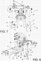
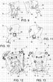
- the thrust member 9 is hinged to the lever 29 by a hinge 32 lockable in the extraction and insertion positions and releasable by means of a locking knob 33 ( figures 9, 10 ).
- the hinge 32 may also comprise a retention spring 34 which facilitates the rotation of the thrust member 9 and keeps it in the chosen position.
- the thrust assembly 8 comprises a counter frame 35 rigidly connected to the frame 5 and having two counter surfaces 36 opposite and directly facing the rail 3, preferably at the profile of the rail base, or at the joint 13 of the tie 4, on two opposite sides of the rail, so as to form a counter support during an extraction movement of the thrust assembly 8.
- the counter-frame 35 is in the shape of a horseshoe, suitable to extend astride the rail profile and the thrust members 9 are movable with respect to the counter-frame 35 moving towards each other (insertion) or away from each other (extraction) transversally to the longitudinal direction of the rail 3. This way torques on the machine caused by the extraction thrust are avoided and the risk of tipping over the machine 1 itself is overcome.
- the frame 5 may form a platform or central portion 37 to which the thrust assembly 8 and the actuation assembly 14 is connected, a front supporting arm 38 extending from the central portion 37 toward a front side of the machine 1 and having one or more rollers 6 for a front support of the frame 5 on the rail 3, and a rear support arm 39 extending from the central portion 37 toward a rear side of the machine 1 and having at least one roller 7 for a rear support of the frame 5 on the rail 3.
- the rear arm 39 is connected with the central portion 37 by a rotary joint 40 with a spring 41 that is preloaded as to solicit (with the machine 1 resting on the rail) the central portion 37 with the thrust assembly 8 against the force of gravity upwards in a raised waiting position with respect to the front and rear supports (rollers 6, 7) and to allow the operator to push the central portion 37 with the thrust assembly 8 against the spring pre-load 41 downwards in a lowered position where the thrust members 9 can engage the connecting fasteners 2 positioned on the tie 4 (and possibly partially pre-inserted in the mounting attachments 13).
- the preload of the spring which acts between the central portion 37 and the rear arm 39 of the frame 5 is adjustable to adjust the raised waiting position and be able to adapt the resistance of the frame 5 to lowering, to the individual preferences of the user. This facilitates the use of the application machine 1 and reduces operator fatigue.
- the spring 41 comprises a gas spring connected to a first point or fulcrum 42 in the rear arm 39 away from the rotary joint 40 and a second point or fulcrum 43 of the central portion 37 away from the rotary joint and from the first fulcrum 42 so that the central portion 37, the rear arm 39 and the air spring 41 form an articulated triangle, and wherein the position or distance of one of the first 42 and second points or fulcrums 43 (preferably of the second point 43) in relation to the rotary joint 40 is adjustable, for example by means of an adjusting screw 44 with a manual knob to adjust the preload torque exerted by the air spring on the axis of the rotary joint 40.
- the thrust assembly 8 comprises a lifting device 45 to lift the tie against the rail, and the control device 19 drives the lifting device 45 automatically depending on the actuation of the oleo-dynamic actuator 10, so that the lifting of the tie 4 takes place during an initial phase of insertion of the Fastclip fastener in which the Fastclip fastener does not yet engage the profile of the rail base 3 but is already partially fitted into the joint 13 of the tie 4 and the joint 13 of the tie 4 is thus already engaged with the thrust member 9.
- the lifting device 45 comprises:
- the lifting piston 47 is moved by an oleo-dynamic piston-cylinder lifting assembly 48 automatically controlled depending on the oleo-dynamic pressure in the oleo-dynamic actuator 10, in particular by means of a group of pressure-controlled passive valves 49.
- the insertion cycle of the Fastclip springs occurs in the following sequence:
- the user actuates the control member 51 and the control device 19 drives the control valves 18 of the oleo-dynamic circuit 17 which supplies pressurised oil to the oleo-dynamic actuator 10.
- the oleo-dynamic actuator 10 moves from the rest position toward the insertion position and the thrust members engage the Fastclip fasteners and insert the palettes 46 under the latter.
- the thrust members 9 push the Fastclip fasteners into the corresponding joints 13 of the tie 4 and the resistance to the insertion of the connecting fasteners increases the pressure of the oleo-dynamic fluid in the actuator 10.
- the group of pressure-controlled passive valves 49 switches the oleo-dynamic circuit 17, so as to stop or slow down the further advancement of the oleo-dynamic actuator 10 and (pressurise the oleo-dynamic piston-cylinder lifting assembly 48 so as to) lower the lifting piston 47 against the rail 3 so that the thrust members 9 lift the tie 4 to rest against the rail 3.
- the support of the tie against the rail entails an increase of the fluid pressure up to a further threshold value, which ensures the lifting of the tie against the rail, upon the achievement of which the group of pressure-controlled passive valves 49 switches the oleo-dynamic circuit 17, so that the oleo-dynamic actuator 10 and the thrust members 9 continue their stroke as far as the insertion position, completing the insertion of the Fastclip fastener above the rail base with the tie 4 moved correctly towards the latter.
- the control device 19 comprises a cycle selection member 50, for example a lever, knob, or push-button for a manual selection between an application cycle of the connecting fasteners 2 and a removal cycle of the connecting fasteners 2 (differing substantially in the direction of movement of the oleo-dynamic actuator 10), as well as an actuating member 51, for example a push-button, for the manual actuation of the cycle pre-selected by the cycle selection member 50, wherein the same actuating member 51 actuates both the application and the removal cycles of the connection fasteners 2.
- a cycle selection member 50 for example a lever, knob, or push-button for a manual selection between an application cycle of the connecting fasteners 2 and a removal cycle of the connecting fasteners 2 (differing substantially in the direction of movement of the oleo-dynamic actuator 10)
- an actuating member 51 for example a push-button
- control device 19 comprises a memory and stores in the memory the number of insertion/extraction cycles and/or the total number of hours of operation, and generates an acoustic and/or visual maintenance alert depending on the number of hours of operation and/or of the number of cycles and predetermined maintenance intervals.
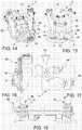
- the actuating assembly 14 forms a module that is free-standing and removably connectable to the frame 5, and comprises two front handles 52 formed on a front side of the actuating assembly 14 and two rear handles 53 formed on a rear side of the actuating assembly 14 which permit the gripping and transport of the actuating assembly 14 by two people (one in front and one behind), as well an operating handle 54 with two handles 55 and at least one actuating member 51, for example a push-button or a lever, wherein the operating handle 54 is movable, for example, can be tipped between an operative position, wherein the operating handle 54 is extended outwardly of the actuating assembly 14 in the direction of the rear side, and a transport position, wherein the operating handle 54 is collapsed inwardly of the actuating assembly 14.
- the operating handle 54 can be locked in the operative position by a friction or snap locking device 56 configured to:
- the locking device 56 In case of lifting the actuating assembly 14 with the operating handle 54 extended in the operative position, the locking device 56 would gradually yield, preventing actions that could injure the operator or damage the application machine 1.
- the locking device 56 comprises one or more pairs of friction surfaces which can be clamped against one another and detached from one another by means of a locking knob 58.
- the friction surfaces are made, one on the operating handle 54 and the other on a frame of the actuating assembly 14, preferably at a tipping hinge which connects the operating handle 54 to the (frame) of the actuating assembly 14.
- the operating handle 54 can be completely detached from the actuating assembly 14.
- the rear handles 53 are also made on the operating handle 54 near one of its ends opposite the handles 55, and are moved, for example, tipped into the position of use when the operating handle 54 is moved to the collapsed position.
Landscapes
- Engineering & Computer Science (AREA)
- Chemical & Material Sciences (AREA)
- Combustion & Propulsion (AREA)
- Mechanical Engineering (AREA)
- General Engineering & Computer Science (AREA)
- Architecture (AREA)
- Civil Engineering (AREA)
- Structural Engineering (AREA)
- Portable Nailing Machines And Staplers (AREA)
Claims (21)
- Anbringemaschine (1) für das Anbringen und Entfernen von Verbindungselementen (2) zum Verbinden einer Schiene (3) mit einer Schwelle (4) eines Eisenbahngleises, wobei die Anbringemaschine (1) aufweist:- einen Rahmen (5), der auf die Schiene (3) aufsetzbar ist,- eine Schubanordnung (8), die an dem Rahmen (5) angebracht ist und zumindest ein Schubelement (9) aufweist, das zum Eingriff mit dem Verbindungselement (2) geeignet ist, und einen öldynamischen Aktuator (10), der so angeordnet ist, dass er in der Lage ist, das Schubelement (9) in eine Einsetzrichtung (11) zu bewegen, um das Verbindungselement (2) mit der Schiene (3) und mit einer Verbindungsstelle (13) der Schwelle (4) in Eingriff zu bringen, und einer Ausziehrichtung (12), um das Verbindungselement (2) von der Schiene (3) und der Verbindungsstelle (13) der Schwelle (4) zu lösen,- eine Aktivierungsanordnung (14), die an dem Rahmen (5) angebracht ist und einen Verbrennungsmotor (15) mit einem Drehzahlsteller (21) aufweist, eine öldynamische Pumpe (16), die mit dem Motor (15) verbunden ist, und einen öldynamischen Kreislauf (17), der die Pumpe (16) mit dem öldynamischen Aktuator (10) verbindet,- eine Antriebs- und Steuervorrichtung (19), die von einem Fahrer betätigbar ist,dadurch gekennzeichnet, dass die Aktivierungsanordnung (14) ein oder mehrere Steuerventile (18) für die Aktivierung des öldynamischen Aktuators (10) aufweist, und dass die Antriebs- und Steuervorrichtung (19) mit dem Steuerventil (18) verbunden ist, um das Steuerventil (18) zur Steuerung des öldynamischen Aktuators (10) zu steuern,
wobei die Antriebs- und Steuervorrichtung (19) eine Einstellvorrichtung (20) des Drehzahlstellers (21) aufweist, wobei die Einstellvorrichtung (20) die Drehzahl des Motors (15) in Abhängigkeit von der Aktivierung des öldynamischen Aktuators (10) automatisch einstellt. - Die Anbringemaschine (1) nach Anspruch 1, wobei die Einstellvorrichtung (20) den Drehzahlsteller (21) einstellt, um die Drehzahl des Motors (15) während der Aktivierung des öldynamischen Aktuators (10) in Bezug auf eine reduzierte Drehzahl während Nicht-Aktivierungsintervallen des öldynamischen Aktuators (10) zu erhöhen.
- Die Anbringemaschine (1) nach Anspruch 1 oder 2, wobei die Einstellvorrichtung (20) einen Getriebemotor mit einem Kodierer aufweist, der mit dem Drehzahlsteller (21) verbunden ist und geeignet ist, die Position des Drehzahlstellers (21) gemäß einer vorbestimmten Drehzahlstellfunktion einzustellen.
- Die Anbringemaschine (1) nach einem der vorhergehenden Ansprüche, wobei die Pumpe (16) eine zweistufige öldynamische Pumpe ist, die in Abhängigkeit von der Drehzahl des Motors (15) und/oder in Abhängigkeit vom Öldruck des öldynamischen Kreislaufs (17) umschaltet zwischen:- einer zweistufigen Pumpenkonfiguration mit hoher Strömungsrate und reduziertem Druck, und- einer einstufigen Pumpenkonfiguration mit reduzierter Strömungsrate und hohem Druck.
- Die Anbringemaschine (1) nach Anspruch 4, wobei:- bei Überschreiten eines Druckschwellenwerts in dem öldynamischen Kreislauf während Aktivierung des öldynamischen Aktuators (10), die Pumpe (16) von der zweistufigen Konfiguration zur einstufigen Konfiguration schaltet, und- nach Abschluss einer Aktivierung des öldynamischen Aktuators (10), die Pumpe (16) von der einstufigen Konfiguration zur zweistufigen Konfiguration schaltet.
- Die Anbringemaschine (1) nach Anspruch 4 oder 5, wobei die Pumpe (16) eine zweistufige Zahnradpumpe ist.
- Die Anbringemaschine (1) nach einem der vorhergehenden Ansprüche, wobei der öldynamische Kreislauf (17) ein Reservoir (28) aufweist, das eine Einlassöffnung (25), eine Auslassöffnung (26), eine Kühlwand (27) mit Kühlrippen, die auswärts des Reservoirs (24) vorstehen, und einen inneren Ölweg (28), der sich von der Einlassöffnung (25) bis zur der Auslassöffnung (26) erstreckt und eine Wärmeaustauschlänge hat, die zwischen der Einlassöffnung und Auslassöffnung angeordnet ist, und sich entlang der Kühlwand (27) erstreckt, bildet.
- Die Anbringemaschine (1) nach einem der vorhergehenden Ansprüche, wobei die Schubanordnung (8) zwei gegenüberliegende Hebel (29) aufweist, die von zwei Seiten des Rahmens (5) um jeweilige Achsen herum drehbar angebracht sind, und nur einen öldynamischen Aktuator (10), der mit beiden Hebeln (29) verbunden ist, um diese in Gegenrichtung zu bewegen, wobei an jedem der zwei Hebel (29) eines der Schubelemente (9) angebracht ist, und- jedes der Schubelemente (9) an seinem ersten Ende ein Einsetzwerkzeug (30) zum Einsetzen des Verbindungselements (2) und an seinem zweiten Ende ein Ausziehwerkzeug (31) zum Ausziehen des Verbindungselements (2) bildet, und- jedes der Schubelemente (9) umgedreht werden kann zwischen:- einer Ausziehposition, in der das Ausziehwerkzeug (31) von dem Hebel (29) vorsteht, um in der Lage zu sein, das eingesetzte Verbindungselement (2) zu ergreifen und herauszuziehen,- einer Einsetzposition, in der das Einsetzwerkzeug (30) von dem Hebel (29) vorsteht, um in der Lage zu sein, das gelöste Verbindungselement (2) zu ergreifen und einzusetzen.
- Die Anbringemaschine (1) nach Anspruch 8, wobei das Schubelement (9) an dem Hebel (29) durch ein mit einer Feder (34) versehenes Gelenk (32) angelenkt ist, um die Drehung des Schubelements zu erleichtern und das Schubelement an der gewählten Position zu halten.
- Die Anbringemaschine (1) nach einem der vorhergehenden Ansprüche, wobei die Schubanordnung (9) einen Gegenrahmen (35) aufweist, der mit dem Rahmen (5) starr verbunden ist und zwei entgegengesetzte Gegenflächen (36) aufweist, die so angeordnet sind, dass sie direkt zur Schiene (3) oder zur Verbindungsstelle (13) der Schwelle (4) weisen, um während einer Ausziehbewegung der Schubanordnung (9) an zwei entgegengesetzten Seiten der Schiene eine Gegenstütze zu bilden.
- Die Anbringemaschine (1) nach Anspruch 10, wobei der Gegenrahmen (35) hufeisenförmig und geeignet ist, sich über das Schienenprofil hinweg zu erstrecken, so dass er gegen die Schienenbasis an zwei entgegengesetzten Seiten abgestützt werden kann, und die Schubelemente (9) in Bezug auf den Gegenrahmen (35) bewegbar sind, wobei sie sich quer zur Längsrichtung der Schiene (3) aufeinander zu oder voneinander weg bewegen.
- Die Anbringemaschine (1) nach einem der vorhergehenden Ansprüche, wobei der Rahmen (5) bildet:- eine mittlere Plattform (37), mit der die Schubanordnung (8) und die Aktivierungsanordnung (14) verbunden sind,- einen vorderen Tragarm (38), der sich von der mittleren Plattform (37) zur Vorderseite der Maschine (1) erstreckt und eine oder mehrere Rollen (6) aufweist, um den Rahmen (5) auf der Schiene (3) vorne zu stützen,- einen hinteren Tragarm (39), der sich von der mittleren Plattform (37) zur Rückseite der Maschine (1) erstreckt und zumindest eine Rolle (7) aufweist, um den Rahmen (5) auf der Schiene (3) hinten zu stützen, aufweist,wobei der hintere Arm (39) mit dem mittleren Abschnitt (37) durch ein Drehgelenk (40) mit einer Feder (41) verbunden ist, die so vorbelastet ist, um:- Erlauben, wenn der Rahmen (5) auf der Schiene aufliegt, den mittleren Abschnitt (37) mit der Schubanordnung (8) in Bezug auf die Schiene abzusenken und anzuheben, und- das Gewicht von zumindest einem Teil des mittleren Abschnitts (37) mit der Schubanordnung (8) auszugleichen,wobei die Vorlast der Feder (41) einstellbar ist, um in der Lage zu sein, den Rahmenwiderstand zum Absenken und Anheben des mittleren Abschnitts (37) mit der Schubanordnung (8) einzustellen.
- Die Anbringemaschine (1) nach Anspruch 12, wobei die Feder (41) eine Gasfeder aufweist, die mit einer ersten Stütze (42) in dem hinteren Arm (39) von dem Drehgelenk (40) weg und mit einer zweiten Stütze (43) des mittleren Abschnitts (37) von dem Drehgelenk und der ersten Stütze (42) weg verbunden ist, so dass der mittlere Abschnitt (37), der hintere Arm (39) und die Gasfeder (41) ein gelenkiges Dreieck bilden, und wobei die Position der zweiten Stütze (43) in Bezug auf das Drehgelenk (40) eingestellt werden kann.
- Die Anbringemaschine (1) nach einem der vorhergehenden Ansprüche, wobei die Schubanordnung (8) eine Hubvorrichtung (45) aufweist, um die Schwelle gegen die Schiene anzuheben, und die Steuervorrichtung (19) die Hubvorrichtung (45) in Abhängigkeit von der Aktivierung des öldynamischen Aktuators (10) automatisch aktiviert, so dass das Anheben der Schwelle (4) während der Anfangsstufe des Einsetzens des Verbindungselements (2) erfolgt, indem es bereits teilweise in die Verbindungsstelle (13) des Verbinders (4) eingesetzt ist.
- Die Anbringemaschine (1) nach Anspruch 14, wobei die Hubvorrichtung (45) aufweist:- eine Palette (46), die von einer Unterseite des Einsetzwerkzeugs (30) des Schubelements (9) einwärts der Schubanordnung (8) vorsteht, um es unter das Verbindungselement (2) einzusetzen, wenn das Einsetzwerkzeug (30) das Verbindungselement (2) ergreift, das partiell in die Verbindungsstelle (13) der Schwelle (4) eingesetzt ist,- einen Hubkolben (47), der von oben auf der Schiene (3) aufliegt und sich abwärts bewegt, um die gesamte Schubanordnung (8) in Bezug auf die Schiene (3) anzuheben und sich der mit den Schubelementen (9) gekoppelten Schwelle (4) zur Basis der Schiene (3) annähert.
- Die Anbringemaschine (1) nach Anspruch 15, wobei der Hubkolben (47) durch eine öldynamische Hubzylinderkolbenanordnung (48) bewegt wird, die durch eine Gruppe von Fluiddruck-gesteuerten passiven Ventilen (49) automatisch angetrieben wird, die in Abhängigkeit vom öldynamischen Druck in dem öldynamischen Aktuator (10) schalten.
- Die Anbringemaschine (1) nach einem der vorhergehenden Ansprüche, wobei die Steuervorrichtung (19) ein Zykluswählelement (50) zur manuellen Auswahl zwischen einem Anwendungszyklus und der Verbindungselemente (2) und einem Entfernungszyklus der Verbindungselemente (2) aufweist, sowie ein Betätigungselement (51) zur manuellen Betätigung des zuvor vom Zykluswählelement (50) gewählten Zyklus, wobei dasselbe Betätigungselement (51) beide Anwendungs- und Entfernungszyklen der Verbindungselemente (2) aktiviert.
- Die Anbringemaschine (1) nach einem der vorhergehenden Ansprüche, wobei die Steuervorrichtung (19) einen Speicher aufweist und in dem Speicher die Anzahl von Einsetz- und/oder Ausziehzyklen und/oder die Gesamtanzahl von Betriebszyklen speichert, und eine akustische und/oder visuelle Wartungswarnung als Funktion der Anzahl der Betriebsstunden und/oder Anzahl von Zyklen und vorbestimmten Wartungsintervallen ausgibt.
- Die Anbringemaschine (1) nach einem der vorhergehenden Ansprüche, wobei die Aktivierungsanordnung (14) ein Modul ist, das freistehend ist und mit dem Rahmen (5) entfernbar verbindbar ist, und sie zwei vordere Griffe (52) aufweist, die an einer Vorderseite der Aktivierungsanordnung (14) ausgebildet sind, und zwei hintere Griffe (53), die an der Rückseite der Aktivierungsanordnung (14) ausgebildet sind, sowie einen Bedienungsgriff (54) mit zwei Griffen (55) und zumindest einem Benutzeraktivierungselement (51),
wobei der Bedienungsgriff (54) angeordnet werden kann zwischen:- einer Arbeitsposition, in der sich der Bedienungsgriff (54) aus der Aktivierungsanordnung (14) in Richtung zur Rückseite hin erstreckt, und- einer Transportposition, in der der Bedienungsgriff (54) in die Aktivierungsanordnung (14) eingefahren ist. - Die Anbringemaschine (1) nach Anspruch 19, wobei der Bedienungsgriff (54) zwischen der Transportposition und der Arbeitsposition drehbar ist, und wobei die Arbeitsposition einstellbar ist,
wobei die Anbringemaschine (1) eine Reib- oder Schnapparretiervorrichtung (56) aufweist, um den Bedienungsgriff (54) in der ausgewählten Betriebsposition zu arretieren, wobei die Arretiervorrichtung (56) konfiguriert ist, um:- den Bedienungsgriff (54) in der gewählten Betriebsposition arretiert zu halten, bis ein Drehmomentschwellenwert unter einem Grenzdrehmoment erreicht wird, das zu einer Beschädigung des Bedienungsgriffs (54) führen würde, und- bei Überschreiten des Drehmomentschwellenwerts eine Drehung des Bedienungsgriffs (54) aus der Betriebsposition heraus zu erlauben. - Die Anbringemaschine (1) nach Anspruch 19, wobei der Bedienungsgriff (54) von der Aktivierungsanordnung (14) vollständig abnehmbar ist.
Applications Claiming Priority (2)
| Application Number | Priority Date | Filing Date | Title |
|---|---|---|---|
| ITMI20140813 | 2014-05-05 | ||
| PCT/IB2015/051613 WO2015170199A1 (en) | 2014-05-05 | 2015-03-05 | Machine for the application and / or removal of connecting fasteners for rails |
Publications (2)
| Publication Number | Publication Date |
|---|---|
| EP3140457A1 EP3140457A1 (de) | 2017-03-15 |
| EP3140457B1 true EP3140457B1 (de) | 2019-04-10 |
Family
ID=51136599
Family Applications (1)
| Application Number | Title | Priority Date | Filing Date |
|---|---|---|---|
| EP15711872.0A Active EP3140457B1 (de) | 2014-05-05 | 2015-03-05 | Maschine zur anwendung und/oder entfernung von verbindungselementen für schienen |
Country Status (4)
| Country | Link |
|---|---|
| EP (1) | EP3140457B1 (de) |
| AU (1) | AU2015257417A1 (de) |
| CA (1) | CA2946817A1 (de) |
| WO (1) | WO2015170199A1 (de) |
Families Citing this family (4)
| Publication number | Priority date | Publication date | Assignee | Title |
|---|---|---|---|---|
| KR20190052654A (ko) | 2016-09-19 | 2019-05-16 | 슈비하크 아게 | 스핀들-스크류 클리핑 기계용 파지 기구 |
| IT201700040572A1 (it) * | 2017-04-12 | 2018-10-12 | Cembre Spa | Utensile a batteria per il fissaggio di clips per rotaie mediante un corpo di bloccaggio |
| RU2656740C1 (ru) * | 2017-08-08 | 2018-06-06 | Общество с ограниченной ответственностью "Холдинг АРС" | Устройство для монтажа и демонтажа элементов рельсовых креплений |
| CN112900170A (zh) * | 2019-11-19 | 2021-06-04 | 中国铁建高新装备股份有限公司 | 一种单趾弹条安装和拆卸装置 |
Family Cites Families (6)
| Publication number | Priority date | Publication date | Assignee | Title |
|---|---|---|---|---|
| US1670007A (en) * | 1926-01-23 | 1928-05-15 | Christian H Rasmussen | Power car |
| US4658583A (en) | 1984-06-11 | 1987-04-21 | Trw Inc. | Double staged, internal rotary pump with flow control |
| GB9503406D0 (en) | 1995-02-21 | 1995-04-12 | Haaheim Lars R | Detection of antibody production |
| US7574961B2 (en) * | 2004-03-16 | 2009-08-18 | Cembre S.P.A. | Device for the application and/or removal of rail clips |
| SE528641C2 (sv) * | 2004-09-17 | 2007-01-09 | Rosenqvist Rail Tech Ab | Ett av en operatör lätt manövrerbart arrangemang |
| US8627797B2 (en) * | 2009-06-11 | 2014-01-14 | Illinois Tool Works Inc. | Automatic start and stop of a portable engine driven power source |
-
2015
- 2015-03-05 EP EP15711872.0A patent/EP3140457B1/de active Active
- 2015-03-05 WO PCT/IB2015/051613 patent/WO2015170199A1/en not_active Ceased
- 2015-03-05 AU AU2015257417A patent/AU2015257417A1/en not_active Abandoned
- 2015-03-05 CA CA2946817A patent/CA2946817A1/en not_active Abandoned
Non-Patent Citations (1)
| Title |
|---|
| None * |
Also Published As
| Publication number | Publication date |
|---|---|
| WO2015170199A1 (en) | 2015-11-12 |
| EP3140457A1 (de) | 2017-03-15 |
| CA2946817A1 (en) | 2015-11-12 |
| AU2015257417A1 (en) | 2016-11-03 |
Similar Documents
| Publication | Publication Date | Title |
|---|---|---|
| EP3140457A1 (de) | Maschine zur anwendung und/oder beseitigung von verbindungselementen für schienen | |
| KR101815628B1 (ko) | 드릴링 및 태핑머신의 드릴링축 승강 구동장치 | |
| CN105364798A (zh) | 具有伸缩功能的内燃机翻转机 | |
| CN209628260U (zh) | 林业苗木移栽装置 | |
| EP2025901A3 (de) | Kraftstoffzumessystem mit minimaler Wärmezuführung | |
| CN116180734B (zh) | 一种公路板桩壁安装装置 | |
| CN109004562A (zh) | 一种用于室内铠装开关柜转运、安装的组合装置及其使用方法 | |
| CN119040604B (zh) | 一种齿轮加工用自动热处理装置 | |
| RU142666U1 (ru) | Устройство для обслуживания промежуточного рельсового скрепления типа арс | |
| US9528331B1 (en) | Pipe fitting assembly apparatus | |
| CN107775333A (zh) | 一种涡轮增压核心组件装配装置 | |
| CN110144232B (zh) | 焦炉格子砖安装装置、移动平台以及施工方法 | |
| KR100881708B1 (ko) | 맨웨이 커버용 리프트 | |
| CN106159753A (zh) | 一种具有强散热功能的配电柜 | |
| CN209306481U (zh) | 智能化螺纹板半自动清洗流水线 | |
| CN204449836U (zh) | 电动车前叉压碗机 | |
| CN222390216U (zh) | 一种处理沥青混凝土冷接缝、麻面小型工具 | |
| CN209892337U (zh) | 发动机盘车装置 | |
| CN212743299U (zh) | 移动式脚手架 | |
| CN210089504U (zh) | 一种三靶标升降靶机 | |
| CN220748228U (zh) | 一种抽油机平衡块防脱移位调节装置 | |
| CN112779412A (zh) | 一种轨道交通用针对轴承座热处理装置 | |
| CN119772566B (zh) | 一种电力铁塔螺栓紧固机器人 | |
| CN2482043Y (zh) | 燃气加热炉出料转送装置 | |
| CN223338821U (zh) | 一种燃气热水器热交换器安装工装 |
Legal Events
| Date | Code | Title | Description |
|---|---|---|---|
| STAA | Information on the status of an ep patent application or granted ep patent |
Free format text: STATUS: THE INTERNATIONAL PUBLICATION HAS BEEN MADE |
|
| PUAI | Public reference made under article 153(3) epc to a published international application that has entered the european phase |
Free format text: ORIGINAL CODE: 0009012 |
|
| STAA | Information on the status of an ep patent application or granted ep patent |
Free format text: STATUS: REQUEST FOR EXAMINATION WAS MADE |
|
| 17P | Request for examination filed |
Effective date: 20161014 |
|
| AK | Designated contracting states |
Kind code of ref document: A1 Designated state(s): AL AT BE BG CH CY CZ DE DK EE ES FI FR GB GR HR HU IE IS IT LI LT LU LV MC MK MT NL NO PL PT RO RS SE SI SK SM TR |
|
| AX | Request for extension of the european patent |
Extension state: BA ME |
|
| DAV | Request for validation of the european patent (deleted) | ||
| DAX | Request for extension of the european patent (deleted) | ||
| GRAP | Despatch of communication of intention to grant a patent |
Free format text: ORIGINAL CODE: EPIDOSNIGR1 |
|
| STAA | Information on the status of an ep patent application or granted ep patent |
Free format text: STATUS: GRANT OF PATENT IS INTENDED |
|
| INTG | Intention to grant announced |
Effective date: 20180817 |
|
| RIN1 | Information on inventor provided before grant (corrected) |
Inventor name: GERARDINI, DAVIDE Inventor name: BAREZZANI, GUALTIERO Inventor name: BRAGA, CESARE |
|
| GRAJ | Information related to disapproval of communication of intention to grant by the applicant or resumption of examination proceedings by the epo deleted |
Free format text: ORIGINAL CODE: EPIDOSDIGR1 |
|
| STAA | Information on the status of an ep patent application or granted ep patent |
Free format text: STATUS: REQUEST FOR EXAMINATION WAS MADE |
|
| GRAS | Grant fee paid |
Free format text: ORIGINAL CODE: EPIDOSNIGR3 |
|
| STAA | Information on the status of an ep patent application or granted ep patent |
Free format text: STATUS: GRANT OF PATENT IS INTENDED |
|
| GRAP | Despatch of communication of intention to grant a patent |
Free format text: ORIGINAL CODE: EPIDOSNIGR1 |
|
| INTC | Intention to grant announced (deleted) | ||
| INTG | Intention to grant announced |
Effective date: 20181206 |
|
| GRAA | (expected) grant |
Free format text: ORIGINAL CODE: 0009210 |
|
| STAA | Information on the status of an ep patent application or granted ep patent |
Free format text: STATUS: THE PATENT HAS BEEN GRANTED |
|
| AK | Designated contracting states |
Kind code of ref document: B1 Designated state(s): AL AT BE BG CH CY CZ DE DK EE ES FI FR GB GR HR HU IE IS IT LI LT LU LV MC MK MT NL NO PL PT RO RS SE SI SK SM TR |
|
| REG | Reference to a national code |
Ref country code: GB Ref legal event code: FG4D |
|
| REG | Reference to a national code |
Ref country code: CH Ref legal event code: EP Ref country code: AT Ref legal event code: REF Ref document number: 1118799 Country of ref document: AT Kind code of ref document: T Effective date: 20190415 |
|
| REG | Reference to a national code |
Ref country code: IE Ref legal event code: FG4D |
|
| REG | Reference to a national code |
Ref country code: DE Ref legal event code: R096 Ref document number: 602015027985 Country of ref document: DE |
|
| REG | Reference to a national code |
Ref country code: NL Ref legal event code: MP Effective date: 20190410 |
|
| REG | Reference to a national code |
Ref country code: LT Ref legal event code: MG4D |
|
| REG | Reference to a national code |
Ref country code: AT Ref legal event code: MK05 Ref document number: 1118799 Country of ref document: AT Kind code of ref document: T Effective date: 20190410 |
|
| PG25 | Lapsed in a contracting state [announced via postgrant information from national office to epo] |
Ref country code: NL Free format text: LAPSE BECAUSE OF FAILURE TO SUBMIT A TRANSLATION OF THE DESCRIPTION OR TO PAY THE FEE WITHIN THE PRESCRIBED TIME-LIMIT Effective date: 20190410 |
|
| PG25 | Lapsed in a contracting state [announced via postgrant information from national office to epo] |
Ref country code: NO Free format text: LAPSE BECAUSE OF FAILURE TO SUBMIT A TRANSLATION OF THE DESCRIPTION OR TO PAY THE FEE WITHIN THE PRESCRIBED TIME-LIMIT Effective date: 20190710 Ref country code: FI Free format text: LAPSE BECAUSE OF FAILURE TO SUBMIT A TRANSLATION OF THE DESCRIPTION OR TO PAY THE FEE WITHIN THE PRESCRIBED TIME-LIMIT Effective date: 20190410 Ref country code: HR Free format text: LAPSE BECAUSE OF FAILURE TO SUBMIT A TRANSLATION OF THE DESCRIPTION OR TO PAY THE FEE WITHIN THE PRESCRIBED TIME-LIMIT Effective date: 20190410 Ref country code: PT Free format text: LAPSE BECAUSE OF FAILURE TO SUBMIT A TRANSLATION OF THE DESCRIPTION OR TO PAY THE FEE WITHIN THE PRESCRIBED TIME-LIMIT Effective date: 20190910 Ref country code: SE Free format text: LAPSE BECAUSE OF FAILURE TO SUBMIT A TRANSLATION OF THE DESCRIPTION OR TO PAY THE FEE WITHIN THE PRESCRIBED TIME-LIMIT Effective date: 20190410 Ref country code: AL Free format text: LAPSE BECAUSE OF FAILURE TO SUBMIT A TRANSLATION OF THE DESCRIPTION OR TO PAY THE FEE WITHIN THE PRESCRIBED TIME-LIMIT Effective date: 20190410 Ref country code: ES Free format text: LAPSE BECAUSE OF FAILURE TO SUBMIT A TRANSLATION OF THE DESCRIPTION OR TO PAY THE FEE WITHIN THE PRESCRIBED TIME-LIMIT Effective date: 20190410 Ref country code: LT Free format text: LAPSE BECAUSE OF FAILURE TO SUBMIT A TRANSLATION OF THE DESCRIPTION OR TO PAY THE FEE WITHIN THE PRESCRIBED TIME-LIMIT Effective date: 20190410 |
|
| PG25 | Lapsed in a contracting state [announced via postgrant information from national office to epo] |
Ref country code: BG Free format text: LAPSE BECAUSE OF FAILURE TO SUBMIT A TRANSLATION OF THE DESCRIPTION OR TO PAY THE FEE WITHIN THE PRESCRIBED TIME-LIMIT Effective date: 20190710 Ref country code: RS Free format text: LAPSE BECAUSE OF FAILURE TO SUBMIT A TRANSLATION OF THE DESCRIPTION OR TO PAY THE FEE WITHIN THE PRESCRIBED TIME-LIMIT Effective date: 20190410 Ref country code: LV Free format text: LAPSE BECAUSE OF FAILURE TO SUBMIT A TRANSLATION OF THE DESCRIPTION OR TO PAY THE FEE WITHIN THE PRESCRIBED TIME-LIMIT Effective date: 20190410 Ref country code: GR Free format text: LAPSE BECAUSE OF FAILURE TO SUBMIT A TRANSLATION OF THE DESCRIPTION OR TO PAY THE FEE WITHIN THE PRESCRIBED TIME-LIMIT Effective date: 20190711 Ref country code: PL Free format text: LAPSE BECAUSE OF FAILURE TO SUBMIT A TRANSLATION OF THE DESCRIPTION OR TO PAY THE FEE WITHIN THE PRESCRIBED TIME-LIMIT Effective date: 20190410 |
|
| PG25 | Lapsed in a contracting state [announced via postgrant information from national office to epo] |
Ref country code: AT Free format text: LAPSE BECAUSE OF FAILURE TO SUBMIT A TRANSLATION OF THE DESCRIPTION OR TO PAY THE FEE WITHIN THE PRESCRIBED TIME-LIMIT Effective date: 20190410 Ref country code: IS Free format text: LAPSE BECAUSE OF FAILURE TO SUBMIT A TRANSLATION OF THE DESCRIPTION OR TO PAY THE FEE WITHIN THE PRESCRIBED TIME-LIMIT Effective date: 20190810 |
|
| REG | Reference to a national code |
Ref country code: DE Ref legal event code: R097 Ref document number: 602015027985 Country of ref document: DE |
|
| PG25 | Lapsed in a contracting state [announced via postgrant information from national office to epo] |
Ref country code: RO Free format text: LAPSE BECAUSE OF FAILURE TO SUBMIT A TRANSLATION OF THE DESCRIPTION OR TO PAY THE FEE WITHIN THE PRESCRIBED TIME-LIMIT Effective date: 20190410 Ref country code: SK Free format text: LAPSE BECAUSE OF FAILURE TO SUBMIT A TRANSLATION OF THE DESCRIPTION OR TO PAY THE FEE WITHIN THE PRESCRIBED TIME-LIMIT Effective date: 20190410 Ref country code: EE Free format text: LAPSE BECAUSE OF FAILURE TO SUBMIT A TRANSLATION OF THE DESCRIPTION OR TO PAY THE FEE WITHIN THE PRESCRIBED TIME-LIMIT Effective date: 20190410 Ref country code: DK Free format text: LAPSE BECAUSE OF FAILURE TO SUBMIT A TRANSLATION OF THE DESCRIPTION OR TO PAY THE FEE WITHIN THE PRESCRIBED TIME-LIMIT Effective date: 20190410 Ref country code: CZ Free format text: LAPSE BECAUSE OF FAILURE TO SUBMIT A TRANSLATION OF THE DESCRIPTION OR TO PAY THE FEE WITHIN THE PRESCRIBED TIME-LIMIT Effective date: 20190410 |
|
| PLBE | No opposition filed within time limit |
Free format text: ORIGINAL CODE: 0009261 |
|
| STAA | Information on the status of an ep patent application or granted ep patent |
Free format text: STATUS: NO OPPOSITION FILED WITHIN TIME LIMIT |
|
| PG25 | Lapsed in a contracting state [announced via postgrant information from national office to epo] |
Ref country code: SM Free format text: LAPSE BECAUSE OF FAILURE TO SUBMIT A TRANSLATION OF THE DESCRIPTION OR TO PAY THE FEE WITHIN THE PRESCRIBED TIME-LIMIT Effective date: 20190410 Ref country code: IT Free format text: LAPSE BECAUSE OF FAILURE TO SUBMIT A TRANSLATION OF THE DESCRIPTION OR TO PAY THE FEE WITHIN THE PRESCRIBED TIME-LIMIT Effective date: 20190410 |
|
| 26N | No opposition filed |
Effective date: 20200113 |
|
| PG25 | Lapsed in a contracting state [announced via postgrant information from national office to epo] |
Ref country code: TR Free format text: LAPSE BECAUSE OF FAILURE TO SUBMIT A TRANSLATION OF THE DESCRIPTION OR TO PAY THE FEE WITHIN THE PRESCRIBED TIME-LIMIT Effective date: 20190410 |
|
| PGFP | Annual fee paid to national office [announced via postgrant information from national office to epo] |
Ref country code: GB Payment date: 20200323 Year of fee payment: 6 |
|
| PG25 | Lapsed in a contracting state [announced via postgrant information from national office to epo] |
Ref country code: SI Free format text: LAPSE BECAUSE OF FAILURE TO SUBMIT A TRANSLATION OF THE DESCRIPTION OR TO PAY THE FEE WITHIN THE PRESCRIBED TIME-LIMIT Effective date: 20190410 |
|
| PGFP | Annual fee paid to national office [announced via postgrant information from national office to epo] |
Ref country code: FR Payment date: 20200331 Year of fee payment: 6 |
|
| REG | Reference to a national code |
Ref country code: DE Ref legal event code: R119 Ref document number: 602015027985 Country of ref document: DE |
|
| PG25 | Lapsed in a contracting state [announced via postgrant information from national office to epo] |
Ref country code: MC Free format text: LAPSE BECAUSE OF FAILURE TO SUBMIT A TRANSLATION OF THE DESCRIPTION OR TO PAY THE FEE WITHIN THE PRESCRIBED TIME-LIMIT Effective date: 20190410 |
|
| REG | Reference to a national code |
Ref country code: CH Ref legal event code: PL |
|
| REG | Reference to a national code |
Ref country code: BE Ref legal event code: MM Effective date: 20200331 |
|
| PG25 | Lapsed in a contracting state [announced via postgrant information from national office to epo] |
Ref country code: LU Free format text: LAPSE BECAUSE OF NON-PAYMENT OF DUE FEES Effective date: 20200305 |
|
| PG25 | Lapsed in a contracting state [announced via postgrant information from national office to epo] |
Ref country code: IE Free format text: LAPSE BECAUSE OF NON-PAYMENT OF DUE FEES Effective date: 20200305 Ref country code: DE Free format text: LAPSE BECAUSE OF NON-PAYMENT OF DUE FEES Effective date: 20201001 Ref country code: LI Free format text: LAPSE BECAUSE OF NON-PAYMENT OF DUE FEES Effective date: 20200331 Ref country code: CH Free format text: LAPSE BECAUSE OF NON-PAYMENT OF DUE FEES Effective date: 20200331 |
|
| PG25 | Lapsed in a contracting state [announced via postgrant information from national office to epo] |
Ref country code: BE Free format text: LAPSE BECAUSE OF NON-PAYMENT OF DUE FEES Effective date: 20200331 |
|
| GBPC | Gb: european patent ceased through non-payment of renewal fee |
Effective date: 20210305 |
|
| PG25 | Lapsed in a contracting state [announced via postgrant information from national office to epo] |
Ref country code: GB Free format text: LAPSE BECAUSE OF NON-PAYMENT OF DUE FEES Effective date: 20210305 Ref country code: FR Free format text: LAPSE BECAUSE OF NON-PAYMENT OF DUE FEES Effective date: 20210331 |
|
| PG25 | Lapsed in a contracting state [announced via postgrant information from national office to epo] |
Ref country code: MT Free format text: LAPSE BECAUSE OF FAILURE TO SUBMIT A TRANSLATION OF THE DESCRIPTION OR TO PAY THE FEE WITHIN THE PRESCRIBED TIME-LIMIT Effective date: 20190410 Ref country code: CY Free format text: LAPSE BECAUSE OF FAILURE TO SUBMIT A TRANSLATION OF THE DESCRIPTION OR TO PAY THE FEE WITHIN THE PRESCRIBED TIME-LIMIT Effective date: 20190410 |
|
| PG25 | Lapsed in a contracting state [announced via postgrant information from national office to epo] |
Ref country code: MK Free format text: LAPSE BECAUSE OF FAILURE TO SUBMIT A TRANSLATION OF THE DESCRIPTION OR TO PAY THE FEE WITHIN THE PRESCRIBED TIME-LIMIT Effective date: 20190410 |