EP3139590A1 - Mobile device and method of controlling therefor - Google Patents
Mobile device and method of controlling therefor Download PDFInfo
- Publication number
- EP3139590A1 EP3139590A1 EP16162796.3A EP16162796A EP3139590A1 EP 3139590 A1 EP3139590 A1 EP 3139590A1 EP 16162796 A EP16162796 A EP 16162796A EP 3139590 A1 EP3139590 A1 EP 3139590A1
- Authority
- EP
- European Patent Office
- Prior art keywords
- mobile device
- mobile terminal
- option
- memory
- preview
- Prior art date
- Legal status (The legal status is an assumption and is not a legal conclusion. Google has not performed a legal analysis and makes no representation as to the accuracy of the status listed.)
- Ceased
Links
Images


Classifications
-
- H—ELECTRICITY
- H04—ELECTRIC COMMUNICATION TECHNIQUE
- H04W—WIRELESS COMMUNICATION NETWORKS
- H04W4/00—Services specially adapted for wireless communication networks; Facilities therefor
- H04W4/02—Services making use of location information
- H04W4/023—Services making use of location information using mutual or relative location information between multiple location based services [LBS] targets or of distance thresholds
-
- H—ELECTRICITY
- H04—ELECTRIC COMMUNICATION TECHNIQUE
- H04N—PICTORIAL COMMUNICATION, e.g. TELEVISION
- H04N23/00—Cameras or camera modules comprising electronic image sensors; Control thereof
- H04N23/60—Control of cameras or camera modules
- H04N23/63—Control of cameras or camera modules by using electronic viewfinders
- H04N23/631—Graphical user interfaces [GUI] specially adapted for controlling image capture or setting capture parameters
- H04N23/632—Graphical user interfaces [GUI] specially adapted for controlling image capture or setting capture parameters for displaying or modifying preview images prior to image capturing, e.g. variety of image resolutions or capturing parameters
-
- H—ELECTRICITY
- H04—ELECTRIC COMMUNICATION TECHNIQUE
- H04N—PICTORIAL COMMUNICATION, e.g. TELEVISION
- H04N23/00—Cameras or camera modules comprising electronic image sensors; Control thereof
- H04N23/60—Control of cameras or camera modules
- H04N23/62—Control of parameters via user interfaces
-
- H—ELECTRICITY
- H04—ELECTRIC COMMUNICATION TECHNIQUE
- H04B—TRANSMISSION
- H04B1/00—Details of transmission systems, not covered by a single one of groups H04B3/00 - H04B13/00; Details of transmission systems not characterised by the medium used for transmission
- H04B1/38—Transceivers, i.e. devices in which transmitter and receiver form a structural unit and in which at least one part is used for functions of transmitting and receiving
- H04B1/3827—Portable transceivers
- H04B1/3833—Hand-held transceivers
-
- H—ELECTRICITY
- H04—ELECTRIC COMMUNICATION TECHNIQUE
- H04N—PICTORIAL COMMUNICATION, e.g. TELEVISION
- H04N23/00—Cameras or camera modules comprising electronic image sensors; Control thereof
-
- H—ELECTRICITY
- H04—ELECTRIC COMMUNICATION TECHNIQUE
- H04N—PICTORIAL COMMUNICATION, e.g. TELEVISION
- H04N23/00—Cameras or camera modules comprising electronic image sensors; Control thereof
- H04N23/60—Control of cameras or camera modules
- H04N23/63—Control of cameras or camera modules by using electronic viewfinders
- H04N23/633—Control of cameras or camera modules by using electronic viewfinders for displaying additional information relating to control or operation of the camera
-
- H—ELECTRICITY
- H04—ELECTRIC COMMUNICATION TECHNIQUE
- H04N—PICTORIAL COMMUNICATION, e.g. TELEVISION
- H04N23/00—Cameras or camera modules comprising electronic image sensors; Control thereof
- H04N23/60—Control of cameras or camera modules
- H04N23/64—Computer-aided capture of images, e.g. transfer from script file into camera, check of taken image quality, advice or proposal for image composition or decision on when to take image
-
- H—ELECTRICITY
- H04—ELECTRIC COMMUNICATION TECHNIQUE
- H04W—WIRELESS COMMUNICATION NETWORKS
- H04W4/00—Services specially adapted for wireless communication networks; Facilities therefor
- H04W4/12—Messaging; Mailboxes; Announcements
-
- H—ELECTRICITY
- H04—ELECTRIC COMMUNICATION TECHNIQUE
- H04N—PICTORIAL COMMUNICATION, e.g. TELEVISION
- H04N23/00—Cameras or camera modules comprising electronic image sensors; Control thereof
- H04N23/60—Control of cameras or camera modules
- H04N23/617—Upgrading or updating of programs or applications for camera control
-
- H—ELECTRICITY
- H04—ELECTRIC COMMUNICATION TECHNIQUE
- H04N—PICTORIAL COMMUNICATION, e.g. TELEVISION
- H04N23/00—Cameras or camera modules comprising electronic image sensors; Control thereof
- H04N23/60—Control of cameras or camera modules
- H04N23/66—Remote control of cameras or camera parts, e.g. by remote control devices
- H04N23/661—Transmitting camera control signals through networks, e.g. control via the Internet
Definitions
- a mobile device e.g., a mobile phone, a tablet PC, a wearable device, etc.
- various functions including a camera function.
- the capability of the camera mounted on the mobile device is consistently improving.
- the related art mobile device has the following technical problems.
- Another object of the present invention is to provide a user with a technology capable of easily accessing a camera function of high performance.
- Still another object of the present invention is to implement simple options for capturing a picture similar to a picture taken by a professional using various GUIs.
- Another object of the present invention is to provide a user with a solution capable of more promptly sharing information on a picture captured by a specific camera setting condition with other users.
- a method of controlling a mobile device includes the steps of displaying a preview captured by a camera and at least one or more selectable options, selecting a specific option from the at least one or more selectable options, automatically changing at least one or more factors among camera setting information according to the selected specific option with reference to a memory, storing a specific preview captured based on the changed factor in the memory and transmitting image data corresponding to the specific preview and camera setting information used for capturing the specific preview to an external mobile device in response to reception of a command for sharing the specific preview stored in the memory.
- a mobile device includes a camera, a memory, a communication module, a display module configured to display a preview captured by the camera and at least one or more selectable options, an interface module configured to select a specific option from the at least one or more selectable options and a controller configured to control the camera, the memory, the communication module, the display module and the interface module.
- Mobile terminals presented herein may be implemented using a variety of different types of terminals. Examples of such terminals include cellular phones, smart phones, user equipment, laptop computers, digital broadcast terminals, personal digital assistants (PDAs), portable multimedia players (PMPs), navigators, portable computers (PCs), slate PCs, tablet PCs, ultra books, wearable devices (for example, smart watches, smart glasses, head mounted displays (HMDs)), and the like.
- PDAs personal digital assistants
- PMPs portable multimedia players
- PCs portable computers
- slate PCs slate PCs
- tablet PCs tablet PCs
- ultra books ultra books
- wearable devices for example, smart watches, smart glasses, head mounted displays (HMDs)
- the mobile terminal 100 is shown having wireless communication unit 110 configured with several commonly implemented components.
- the wireless communication unit 110 typically includes one or more components which permit wireless communication between the mobile terminal 100 and a wireless communication system or network within which the mobile terminal is located.
- the wireless communication unit 110 typically includes one or more modules which permit communications such as wireless communications between the mobile terminal 100 and a wireless communication system, communications between the mobile terminal 100 and another mobile terminal, communications between the mobile terminal 100 and an external server. Further, the wireless communication unit 110 typically includes one or more modules which connect the mobile terminal 100 to one or more networks. To facilitate such communications, the wireless communication unit 110 includes one or more of a broadcast receiving module 111, a mobile communication module 112, a wireless Internet module 113, a short-range communication module 114, and a location information module 115.
- the sensing unit 140 is typically implemented using one or more sensors configured to sense internal information of the mobile terminal, the surrounding environment of the mobile terminal, user information, and the like.
- the sensing unit 140 is shown having a proximity sensor 141 and an illumination sensor 142.
- the sensing unit 140 may alternatively or additionally include other types of sensors or devices, such as a touch sensor, an acceleration sensor, a magnetic sensor, a G-sensor, a gyroscope sensor, a motion sensor, an RGB sensor, an infrared (IR) sensor, a finger scan sensor, a ultrasonic sensor, an optical sensor (for example, camera 121), a microphone 122, a battery gauge, an environment sensor (for example, a barometer, a hygrometer, a thermometer, a radiation detection sensor, a thermal sensor, and a gas sensor, among others), and a chemical sensor (for example, an electronic nose, a health care sensor, a biometric sensor, and the like), to name a few.
- the mobile terminal 100 may be configured to utilize information obtained from sensing unit 140, and in particular, information obtained from one or more sensors of the sensing unit 140, and combinations thereof.
- the power supply unit 190 can be configured to receive external power or provide internal power in order to supply appropriate power required for operating elements and components included in the mobile terminal 100.
- the power supply unit 190 may include a battery, and the battery may be configured to be embedded in the terminal body, or configured to be detachable from the terminal body.
- the mobile communication module 112 can transmit and/or receive wireless signals to and from one or more network entities.
- a network entity include a base station, an external mobile terminal, a server, and the like.
- Such network entities form part of a mobile communication network, which is constructed according to technical standards or communication methods for mobile communications (for example, Global System for Mobile Communication (GSM), Code Division Multi Access (CDMA), CDMA2000 (Code Division Multi Access 2000), EV-DO (Enhanced Voice-Data Optimized or Enhanced Voice-Data Only), Wideband CDMA (WCDMA), High Speed Downlink Packet access (HSDPA), HSUPA (High Speed Uplink Packet Access), Long Term Evolution (LTE), LTE-A (Long Term Evolution-Advanced), and the like).
- Examples of wireless signals transmitted and/or received via the mobile communication module 112 include audio call signals, video (telephony) call signals, or various formats of data to support communication of text and multimedia messages.
- the wireless Internet module 113 is configured to facilitate wireless Internet access. This module may be internally or externally coupled to the mobile terminal 100.
- the wireless Internet module 113 may transmit and/or receive wireless signals via communication networks according to wireless Internet technologies. Examples of such wireless Internet access include Wireless LAN (WLAN), Wireless Fidelity (Wi-Fi), Wi-Fi Direct, Digital Living Network Alliance (DLNA), Wireless Broadband (WiBro), Worldwide Interoperability for Microwave Access (WiMAX), High Speed Downlink Packet Access (HSDPA), HSUPA (High Speed Uplink Packet Access), Long Term Evolution (LTE), LTE-A (Long Term Evolution-Advanced), and the like.
- the wireless Internet module 113 may transmit/receive data according to one or more of such wireless Internet technologies, and other Internet technologies as well.
- the wireless Internet module 113 when the wireless Internet access is implemented according to, for example, WiBro, HSDPA,HSUPA, GSM, CDMA, WCDMA, LTE, LTE-A and the like, as part of a mobile communication network, the wireless Internet module 113 performs such wireless Internet access. As such, the Internet module 113 may cooperate with, or function as, the mobile communication module 112.
- the short-range communication module 114 is configured to facilitate short-range communications. Suitable technologies for implementing such short-range communications include BLUETOOTHTM, Radio Frequency IDentification (RFID), Infrared Data Association (IrDA), Ultra-WideBand (UWB), ZigBee, Near Field Communication (NFC), Wireless-Fidelity (Wi-Fi), Wi-Fi Direct, Wireless USB (Wireless Universal Serial Bus), and the like.
- the short-range communication module 114 in general supports wireless communications between the mobile terminal 100 and a wireless communication system, communications between the mobile terminal 100 and another mobile terminal 100, or communications between the mobile terminal and a network where another mobile terminal 100 (or an external server) is located, via wireless area networks.
- One example of the wireless area networks is a wireless personal area networks.
- another mobile terminal (which may be configured similarly to mobile terminal 100) may be a wearable device, for example, a smart watch, a smart glass or a head mounted display (HMD), which can exchange data with the mobile terminal 100 (or otherwise cooperate with the mobile terminal 100).
- the short-range communication module 114 may sense or recognize the wearable device, and permit communication between the wearable device and the mobile terminal 100.
- the controller 180 when the sensed wearable device is a device which is authenticated to communicate with the mobile terminal 100, the controller 180, for example, may cause transmission of data processed in the mobile terminal 100 to the wearable device via the short-range communication module 114.
- a user of the wearable device may use the data processed in the mobile terminal 100 on the wearable device. For example, when a call is received in the mobile terminal 100, the user may answer the call using the wearable device. Also, when a message is received in the mobile terminal 100, the user can check the received message using the wearable device.
- a position of the mobile terminal may be acquired using a signal sent from a GPS satellite.
- a position of the mobile terminal can be acquired based on information related to a wireless access point (AP) which transmits or receives a wireless signal to or from the Wi-Fi module.
- AP wireless access point
- the input unit 120 may be configured to permit various types of input to the mobile terminal 120. Examples of such input include audio, image, video, data, and user input.
- Image and video input is often obtained using one or more cameras 121. Such cameras 121 may process image frames of still pictures or video obtained by image sensors in a video or image capture mode. The processed image frames can be displayed on the display unit 151 or stored in memory 170.
- the cameras 121 may be arranged in a matrix configuration to permit a plurality of images having various angles or focal points to be input to the mobile terminal 100. As another example, the cameras 121 may be located in a stereoscopic arrangement to acquire left and right images for implementing a stereoscopic image.
- the user input unit 123 is a component that permits input by a user. Such user input may enable the controller 180 to control operation of the mobile terminal 100.
- the user input unit 123 may include one or more of a mechanical input element (for example, a key, a button located on a front and/or rear surface or a side surface of the mobile terminal 100, a dome switch, a jog wheel, a jog switch, and the like), or a touch-sensitive input, among others.
- the touch-sensitive input may be a virtual key or a soft key, which is displayed on a touch screen through software processing, or a touch key which is located on the mobile terminal at a location that is other than the touch screen.
- the virtual key or the visual key may be displayed on the touch screen in various shapes, for example, graphic, text, icon, video, or a combination thereof.
- the sensing unit 140 is generally configured to sense one or more of internal information of the mobile terminal, surrounding environment information of the mobile terminal, user information, or the like.
- the controller 180 generally cooperates with the sending unit 140 to control operation of the mobile terminal 100 or execute data processing, a function or an operation associated with an application program installed in the mobile terminal based on the sensing provided by the sensing unit 140.
- the sensing unit 140 may be implemented using any of a variety of sensors, some of which will now be described in more detail.
- controller 180 processes data corresponding to proximity touches and proximity touch patterns sensed by the proximity sensor 141, and cause output of visual information on the touch screen.
- the controller 180 can control the mobile terminal 100 to execute different operations or process different data according to whether a touch with respect to a point on the touch screen is either a proximity touch or a contact touch.
- a touch sensor can sense a touch applied to the touch screen, such as display unit 151, using any of a variety of touch methods. Examples of such touch methods include a resistive type, a capacitive type, an infrared type, and a magnetic field type, among others.
- the touch sensor may be configured to convert changes of pressure applied to a specific part of the display unit 151, or convert capacitance occurring at a specific part of the display unit 151, into electric input signals.
- the touch sensor may also be configured to sense not only a touched position and a touched area, but also touch pressure and/or touch capacitance.
- a touch object is generally used to apply a touch input to the touch sensor. Examples of typical touch objects include a finger, a touch pen, a stylus pen, a pointer, or the like.
- the touch sensor and the proximity sensor may be implemented individually, or in combination, to sense various types of touches.
- Such touches includes a short (or tap) touch, a long touch, a multi-touch, a drag touch, a flick touch, a pinch-in touch, a pinch-out touch, a swipe touch, a hovering touch, and the like.
- an ultrasonic sensor may be implemented to recognize position information relating to a touch object using ultrasonic waves.
- the controller 180 may calculate a position of a wave generation source based on information sensed by an illumination sensor and a plurality of ultrasonic sensors. Since light is much faster than ultrasonic waves, the time for which the light reaches the optical sensor is much shorter than the time for which the ultrasonic wave reaches the ultrasonic sensor. The position of the wave generation source may be calculated using this fact. For instance, the position of the wave generation source may be calculated using the time difference from the time that the ultrasonic wave reaches the sensor based on the light as a reference signal.
- the camera 121 typically includes at least one a camera sensor (CCD, CMOS etc.), a photo sensor (or image sensors), and a laser sensor.
- a laser sensor may allow detection of a touch of a physical object with respect to a 3D stereoscopic image.
- the photo sensor may be laminated on, or overlapped with, the display device.
- the photo sensor may be configured to scan movement of the physical object in proximity to the touch screen.
- the photo sensor may include photo diodes and transistors at rows and columns to scan content received at the photo sensor using an electrical signal which changes according to the quantity of applied light. Namely, the photo sensor may calculate the coordinates of the physical object according to variation of light to thus obtain position information of the physical object.
- the display unit 151 is generally configured to output information processed in the mobile terminal 100.
- the display unit 151 may display execution screen information of an application program executing at the mobile terminal 100 or user interface (UI) and graphic user interface (GUI) information in response to the execution screen information.
- UI user interface
- GUI graphic user interface
- the display unit 151 may be implemented as a stereoscopic display unit for displaying stereoscopic images.
- a typical stereoscopic display unit may employ a stereoscopic display scheme such as a stereoscopic scheme (a glass scheme), an auto-stereoscopic scheme (glassless scheme), a projection scheme (holographic scheme), or the like.
- a 3D stereoscopic image may include a left image (e.g., a left eye image) and a right image (e.g., a right eye image).
- a 3D stereoscopic imaging method can be divided into a top-down method in which left and right images are located up and down in a frame, an L-to-R (left-to-right or side by side) method in which left and right images are located left and right in a frame, a checker board method in which fragments of left and right images are located in a tile form, an interlaced method in which left and right images are alternately located by columns or rows, and a time sequential (or frame by frame) method in which left and right images are alternately displayed on a time basis.
- a left image thumbnail and a right image thumbnail can be generated from a left image and a right image of an original image frame, respectively, and then combined to generate a single 3D thumbnail image.
- thumbnail may be used to refer to a reduced image or a reduced still image.
- a generated left image thumbnail and right image thumbnail may be displayed with a horizontal distance difference there between by a depth corresponding to the disparity between the left image and the right image on the screen, thereby providing a stereoscopic space sense.
- a left image and a right image required for implementing a 3D stereoscopic image may be displayed on the stereoscopic display unit using a stereoscopic processing unit.
- the stereoscopic processing unit can receive the 3D image and extract the left image and the right image, or can receive the 2D image and change it into a left image and a right image.
- a haptic module 153 can be configured to generate various tactile effects that a user feels, perceive, or otherwise experience.
- a typical example of a tactile effect generated by the haptic module 153 is vibration.
- the strength, pattern and the like of the vibration generated by the haptic module 153 can be controlled by user selection or setting by the controller. For example, the haptic module 153 may output different vibrations in a combining manner or a sequential manner.
- the haptic module 153 can generate various other tactile effects, including an effect by stimulation such as a pin arrangement vertically moving to contact skin, a spray force or suction force of air through a jet orifice or a suction opening, a touch to the skin, a contact of an electrode, electrostatic force, an effect by reproducing the sense of cold and warmth using an element that can absorb or generate heat, and the like.
- an effect by stimulation such as a pin arrangement vertically moving to contact skin, a spray force or suction force of air through a jet orifice or a suction opening, a touch to the skin, a contact of an electrode, electrostatic force, an effect by reproducing the sense of cold and warmth using an element that can absorb or generate heat, and the like.
- the haptic module 153 can also be implemented to allow the user to feel a tactile effect through a muscle sensation such as the user's fingers or arm, as well as transferring the tactile effect through direct contact. Two or more haptic modules 153 may be provided according to the particular configuration of the mobile terminal 100.
- An optical output module 154 can output a signal for indicating an event generation using light of a light source. Examples of events generated in the mobile terminal 100 may include message reception, call signal reception, a missed call, an alarm, a schedule notice, an email reception, information reception through an application, and the like.
- a signal output by the optical output module 154 may be implemented so the mobile terminal emits monochromatic light or light with a plurality of colors.
- the signal output may be terminated as the mobile terminal senses that a user has checked the generated event, for example.
- the interface unit 160 serves as an interface for external devices to be connected with the mobile terminal 100.
- the interface unit 160 can receive data transmitted from an external device, receive power to transfer to elements and components within the mobile terminal 100, or transmit internal data of the mobile terminal 100 to such external device.
- the interface unit 160 may include wired or wireless headset ports, external power supply ports, wired or wireless data ports, memory card ports, ports for connecting a device having an identification module, audio input/output (I/O) ports, video I/O ports, earphone ports, or the like.
- the interface unit 160 can serve as a passage to allow power from the cradle to be supplied to the mobile terminal 100 or may serve as a passage to allow various command signals input by the user from the cradle to be transferred to the mobile terminal there through.
- Various command signals or power input from the cradle may operate as signals for recognizing that the mobile terminal is properly mounted on the cradle.
- the memory 170 may include one or more types of storage mediums including a Flash memory, a hard disk, a solid state disk, a silicon disk, a multimedia card micro type, a card-type memory (e.g., SD or DX memory, etc.), a Random Access Memory (RAM), a Static Random Access Memory (SRAM), a Read-Only Memory (ROM), an Electrically Erasable Programmable Read-Only Memory (EEPROM), a Programmable Read-Only memory (PROM), a magnetic memory, a magnetic disk, an optical disk, and the like.
- the mobile terminal 100 may also be operated in relation to a network storage device that performs the storage function of the memory 170 over a network, such as the Internet.
- the controller 180 can typically control the general operations of the mobile terminal 100. For example, the controller 180 can set or release a lock state for restricting a user from inputting a control command with respect to applications when a status of the mobile terminal meets a preset condition.
- the power supply unit 190 receives external power or provide internal power and supply the appropriate power required for operating respective elements and components included in the mobile terminal 100.
- the power supply unit 190 may include a battery, which is typically rechargeable or be detachably coupled to the terminal body for charging.
- the power supply unit 190 may include a connection port.
- the connection port may be configured as one example of the interface unit 160 to which an external charger for supplying power to recharge the battery is electrically connected.
- the power supply unit 190 may be configured to recharge the battery in a wireless manner without use of the connection port.
- the power supply unit 190 can receive power, transferred from an external wireless power transmitter, using at least one of an inductive coupling method which is based on magnetic induction or a magnetic resonance coupling method which is based on electromagnetic resonance.
- an inductive coupling method which is based on magnetic induction
- a magnetic resonance coupling method which is based on electromagnetic resonance.
- Various embodiments described herein may be implemented in a computer-readable medium, a machine-readable medium, or similar medium using, for example, software, hardware, or any combination thereof.
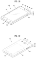
- the mobile terminal 100 is described with reference to a bar-type terminal body.
- the mobile terminal 100 may alternatively be implemented in any of a variety of different configurations. Examples of such configurations include watch-type, clip-type, glasses-type, or as a folder-type, flip-type, slide-type, swing-type, and swivel-type in which two and more bodies are combined with each other in a relatively movable manner, and combinations thereof. Discussion herein will often relate to a particular type of mobile terminal (for example, bar-type, watch-type, glasses-type, and the like). However, such teachings with regard to a particular type of mobile terminal will generally apply to other types of mobile terminals as well.
- the mobile terminal 100 will generally include a case (for example, frame, housing, cover, and the like) forming the appearance of the terminal.
- the case is formed using a front case 101 and a rear case 102.
- Various electronic components are incorporated into a space formed between the front case 101 and the rear case 102.
- At least one middle case may be additionally positioned between the front case 101 and the rear case 102.
- the display unit 151 is shown located on the front side of the terminal body to output information. As illustrated, a window 151a of the display unit 151 may be mounted to the front case 101 to form the front surface of the terminal body together with the front case 101.
- electronic components may also be mounted to the rear case 102. Examples of such electronic components include a detachable battery 191, an identification module, a memory card, and the like.
- Rear cover 103 is shown covering the electronic components, and this cover may be detachably coupled to the rear case 102. Therefore, when the rear cover 103 is detached from the rear case 102, the electronic components mounted to the rear case 102 are externally exposed.
- the rear cover 103 when the rear cover 103 is coupled to the rear case 102, a side surface of the rear case 102 is partially exposed. In some cases, upon the coupling, the rear case 102 may also be completely shielded by the rear cover 103. In some embodiments, the rear cover 103 may include an opening for externally exposing a camera 121b or an audio output module 152b.
- the cases 101, 102, 103 may be formed by injection-molding synthetic resin or may be formed of a metal, for example, stainless steel (STS), aluminum (Al), titanium (Ti), or the like.
- STS stainless steel
- Al aluminum
- Ti titanium
- the mobile terminal 100 may be configured such that one case forms the inner space.
- a mobile terminal 100 having a uni-body is formed so synthetic resin or metal extends from a side surface to a rear surface.
- the mobile terminal 100 may include a waterproofing unit for preventing introduction of water into the terminal body.
- the waterproofing unit may include a waterproofing member which is located between the window 151a and the front case 101, between the front case 101 and the rear case 102, or between the rear case 102 and the rear cover 103, to hermetically seal an inner space when those cases are coupled.
- FIGS. 1B and 1C depict certain components as arranged on the mobile terminal. However, alternative arrangements are possible and within the teachings of the instant disclosure. Some components may be omitted or rearranged.
- the first manipulation unit 123a may be located on another surface of the terminal body
- the second audio output module 152b may be located on the side surface of the terminal body.
- the display unit 151 outputs information processed in the mobile terminal 100.
- the display unit 151 may be implemented using one or more suitable display devices. Examples of such suitable display devices include a liquid crystal display (LCD), a thin film transistor-liquid crystal display (TFT-LCD), an organic light emitting diode (OLED), a flexible display, a 3-dimensional (3D) display, an e-ink display, and combinations thereof.
- the display unit 151 may be implemented using two display devices, which can implement the same or different display technology. For instance, a plurality of the display units 151 may be arranged on one side, either spaced apart from each other, or these devices may be integrated, or these devices may be arranged on different surfaces.
- the display unit 151 may also include a touch sensor which senses a touch input received at the display unit.
- the touch sensor may be configured to sense this touch and the controller 180, for example, may generate a control command or other signal corresponding to the touch.
- the content which is input in the touching manner may be a text or numerical value, or a menu item which can be indicated or designated in various modes.
- the touch sensor may be configured in a form of a film having a touch pattern, disposed between the window 151a and a display on a rear surface of the window 151a, or a metal wire which is patterned directly on the rear surface of the window 151a.
- the touch sensor may be integrally formed with the display.
- the touch sensor may be disposed on a substrate of the display or within the display.
- the window 151a of the display unit 151 will typically include an aperture to permit audio generated by the first audio output module 152a to pass.
- One alternative is to allow audio to be released along an assembly gap between the structural bodies (for example, a gap between the window 151a and the front case 101). In this instance, a hole independently formed to output audio sounds may not be seen or is otherwise hidden in terms of appearance, thereby further simplifying the appearance and manufacturing of the mobile terminal 100.
- the optical output module 154 can be configured to output light for indicating an event generation. Examples of such events include a message reception, a call signal reception, a missed call, an alarm, a schedule notice, an email reception, information reception through an application, and the like.
- the controller can control the optical output unit 154 to stop the light output.
- the first and second manipulation units 123a and 123b are examples of the user input unit 123, which may be manipulated by a user to provide input to the mobile terminal 100.
- the first and second manipulation units 123a and 123b may also be commonly referred to as a manipulating portion, and may employ any tactile method that allows the user to perform manipulation such as touch, push, scroll, or the like.
- the first and second manipulation units 123a and 123b may also employ any non-tactile method that allows the user to perform manipulation such as proximity touch, hovering, or the like.
- FIG. 1B illustrates the first manipulation unit 123a as a touch key, but possible alternatives include a mechanical key, a push key, a touch key, and combinations thereof.
- Input received at the first and second manipulation units 123a and 123b may be used in various ways.
- the first manipulation unit 123a may be used by the user to provide an input to a menu, home key, cancel, search, or the like
- the second manipulation unit 123b may be used by the user to provide an input to control a volume level being output from the first or second audio output modules 152a or 152b, to switch to a touch recognition mode of the display unit 151, or the like.
- a rear input unit may be located on the rear surface of the terminal body.
- the rear input unit can be manipulated by a user to provide input to the mobile terminal 100.
- the input may be used in a variety of different ways.
- the rear input unit may be used by the user to provide an input for power on/off, start, end, scroll, control volume level being output from the first or second audio output modules 152a or 152b, switch to a touch recognition mode of the display unit 151, and the like.
- the rear input unit may be configured to permit touch input, a push input, or combinations thereof.
- the rear input unit may be located to overlap the display unit 151 of the front side in a thickness direction of the terminal body.
- the rear input unit may be located on an upper end portion of the rear side of the terminal body such that a user can easily manipulate it using a forefinger when the user grabs the terminal body with one hand.
- the rear input unit can be positioned at most any location of the rear side of the terminal body.
- Embodiments that include the rear input unit may implement some or all of the functionality of the first manipulation unit 123a in the rear input unit. As such, in situations where the first manipulation unit 123a is omitted from the front side, the display unit 151 can have a larger screen.
- the mobile terminal 100 may include a finger scan sensor which scans a user's fingerprint. The controller 180 can then use fingerprint information sensed by the finger scan sensor as part of an authentication procedure. The finger scan sensor may also be installed in the display unit 151 or implemented in the user input unit 123.
- the microphone 122 is shown located at an end of the mobile terminal 100, but other locations are possible. If desired, multiple microphones may be implemented, with such an arrangement permitting the receiving of stereo sounds.
- the interface unit 160 may serve as a path allowing the mobile terminal 100 to interface with external devices.
- the interface unit 160 may include one or more of a connection terminal for connecting to another device (for example, an earphone, an external speaker, or the like), a port for near field communication (for example, an Infrared Data Association (IrDA) port, a Bluetooth port, a wireless LAN port, and the like), or a power supply terminal for supplying power to the mobile terminal 100.
- the interface unit 160 may be implemented in the form of a socket for accommodating an external card, such as Subscriber Identification Module (SIM), User Identity Module (UIM), or a memory card for information storage.
- SIM Subscriber Identification Module
- UIM User Identity Module
- the second camera 121b is shown located at the rear side of the terminal body and includes an image capturing direction that is substantially opposite to the image capturing direction of the first camera unit 121a. If desired, second camera 121a may alternatively be located at other locations, or made to be moveable, in order to have a different image capturing direction from that which is shown.
- the second camera 121b can include a plurality of lenses arranged along at least one line.
- the plurality of lenses may also be arranged in a matrix configuration.
- the cameras may be referred to as an "array camera.”
- the second camera 121b is implemented as an array camera, images may be captured in various manners using the plurality of lenses and images with better qualities.
- At least one antenna for wireless communication may be located on the terminal body.
- the antenna may be installed in the terminal body or formed by the case.
- an antenna which configures a part of the broadcast receiving module 111 may be retractable into the terminal body.
- an antenna may be formed using a film attached to an inner surface of the rear cover 103, or a case that includes a conductive material.
- the rear cover 103 is shown coupled to the rear case 102 for shielding the battery 191, to prevent separation of the battery 191, and to protect the battery 191 from an external impact or from foreign material.
- the rear case 103 may be detachably coupled to the rear case 102.
- An accessory for protecting an appearance or assisting or extending the functions of the mobile terminal 100 can also be provided on the mobile terminal 100.
- a cover or pouch for covering or accommodating at least one surface of the mobile terminal 100 may be provided.
- the cover or pouch may cooperate with the display unit 151 to extend the function of the mobile terminal 100.
- a touch pen for assisting or extending a touch input to a touch screen is another example of the accessory.
- FIG. 2 is a conceptual view of a deformable mobile terminal according to an alternative embodiment of the present invention.
- mobile terminal 200 is shown having display unit 251, which is a type of display that is deformable by an external force.
- This deformation which includes display unit 251 and other components of mobile terminal 200, may include any of curving, bending, folding, twisting, rolling, and combinations thereof.
- the deformable display unit 251 may also be referred to as a "flexible display unit.”
- the flexible display unit 251 may include a general flexible display, electronic paper (also known as e-paper), and combinations thereof.
- mobile terminal 200 may be configured to include features that are the same or similar to that of mobile terminal 100 of FIGS. 1A-1C .
- the flexible display of mobile terminal 200 is generally formed as a lightweight, non-fragile display, which still exhibits characteristics of a conventional flat panel display, but is instead fabricated on a flexible substrate which can be deformed as noted previously.
- e-paper may be used to refer to a display technology employing the characteristic of a general ink, and is different from the conventional flat panel display in view of using reflected light.
- E-paper is generally understood as changing displayed information using a twist ball or via electrophoresis using a capsule.
- a display region of the flexible display unit 251 includes a generally flat surface.
- the display region may become a curved surface or a bent surface.
- information displayed in the second state may be visual information output on the curved surface.
- the visual information may be realized so a light emission of each unit pixel (sub-pixel) arranged in a matrix configuration is controlled independently.
- the unit pixel denotes an elementary unit for representing one color.
- the first state of the flexible display unit 251 may be a curved state (for example, a state of being curved from up to down or from right to left), instead of being in flat state.
- the flexible display unit 251 may transition to the second state such that the flexible display unit is deformed into the flat state(or a less curved state) or into a more curved state.
- One option is to configure the mobile terminal 200 to include a deformation sensor which senses the deforming of the flexible display unit 251.
- the deformation sensor may be included in the sensing unit 140.
- the deformation sensor may be located in the flexible display unit 251 or the case 201 to sense information related to the deforming of the flexible display unit 251. Examples of such information related to the deforming of the flexible display unit 251 may be a deformed direction, a deformed degree, a deformed position, a deformed amount of time, an acceleration that the deformed flexible display unit 251 is restored, and the like.
- Other possibilities include most any type of information which can be sensed in response to the curving of the flexible display unit or sensed while the flexible display unit 251 is transitioning into, or existing in, the first and second states.
- controller 180 or other component can change information displayed on the flexible display unit 251, or generate a control signal for controlling a function of the mobile terminal 200, based on the information related to the deforming of the flexible display unit 251. Such information is typically sensed by the deformation sensor.
- the mobile terminal 200 is shown having a case 201 for accommodating the flexible display unit 251.
- the case 201 can be deformable together with the flexible display unit 251, taking into account the characteristics of the flexible display unit 251.
- a battery located in the mobile terminal 200 may also be deformable in cooperation with the flexible display unit 261, taking into account the characteristic of the flexible display unit 251.
- One technique to implement such a battery is to use a stack and folding method of stacking battery cells.
- the deformation of the flexible display unit 251 not limited to perform by an external force.
- the flexible display unit 251 can be deformed into the second state from the first state by a user command, application command, or the like.
- a mobile terminal may be configured as a device which is wearable on a human body. Such devices go beyond the usual technique of a user grasping the mobile terminal using their hand. Examples of the wearable device include a smart watch, a smart glass, a head mounted display (HMD), and the like.
- HMD head mounted display
- a typical wearable device can exchange data with (or cooperate with) another mobile terminal 100.
- the wearable device generally has functionality that is less than the cooperating mobile terminal.
- the short-range communication module 114 of a mobile terminal 100 may sense or recognize a wearable device that is near-enough to communicate with the mobile terminal.
- the controller 180 can transmit data processed in the mobile terminal 100 to the wearable device via the short-range communication module 114, for example.
- a user of the wearable device can use the data processed in the mobile terminal 100 on the wearable device. For example, when a call is received in the mobile terminal 100, the user can answer the call using the wearable device. Also, when a message is received in the mobile terminal 100, the user can check the received message using the wearable device.
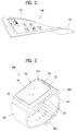
- FIG. 3 is a perspective view illustrating one example of a watch-type mobile terminal 300 in accordance with another exemplary embodiment.
- the watch-type mobile terminal 300 includes a main body 301 with a display unit 351 and a band 302 connected to the main body 301 to be wearable on a wrist.
- mobile terminal 300 may be configured to include features that are the same or similar to that of mobile terminal 100 of FIGS. 1A-1C .
- the main body 301 may include a case having a certain appearance. As illustrated, the case may include a first case 301a and a second case 301b cooperatively defining an inner space for accommodating various electronic components. Other configurations are possible. For instance, a single case may alternatively be implemented, with such a case being configured to define the inner space, thereby implementing a mobile terminal 300 with a uni-body.
- the watch-type mobile terminal 300 can perform wireless communication, and an antenna for the wireless communication can be installed in the main body 301.
- the antenna may extend its function using the case.
- a case including a conductive material may be electrically connected to the antenna to extend a ground area or a radiation area.
- the illustrated embodiment includes audio output module 352, a camera 321, a microphone 322, and a user input unit 323 positioned on the main body 301.
- audio output module 352 When the display unit 351 is implemented as a touch screen, additional function keys may be minimized or eliminated.
- the user input unit 323 may be omitted.
- the band 302 may be used for extending the performance of the antenna.
- the band may include therein a ground extending portion electrically connected to the antenna to extend a ground area.
- the band 302 may include fastener 302a.
- the fastener 302a may be implemented into a buckle type, a snap-fit hook structure, a Velcro® type, or the like, and include a flexible section or material.
- the drawing illustrates an example that the fastener 302a is implemented using a buckle.
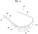
- FIG. 4 is a perspective view illustrating one example of a glass-type mobile terminal 400 according to another exemplary embodiment.
- the glass-type mobile terminal 400 can be wearable on a head of a human body and provided with a frame (case, housing, etc.) therefor.
- the frame may be made of a flexible material to be easily worn.
- the frame of mobile terminal 400 is shown having a first frame 401 and a second frame 402, which can be made of the same or different materials.
- mobile terminal 400 may be configured to include features that are the same or similar to that of mobile terminal 100 of FIGS. 1A-1C .
- the frame may be supported on the head and defines a space for mounting various components.
- electronic components such as a control module 480, an audio output module 452, and the like, may be mounted to the frame part.
- a lens 403 for covering either or both of the left and right eyes may be detachably coupled to the frame part.
- the control module 480 controls various electronic components disposed in the mobile terminal 400.
- the control module 480 may be understood as a component corresponding to the aforementioned controller 180.
- FIG. 4 illustrates that the control module 480 is installed in the frame part on one side of the head, but other locations are possible.
- the display unit 451 may be implemented as a head mounted display (HMD).
- HMD refers to display techniques by which a display is mounted to a head to show an image directly in front of a user's eyes.
- the display unit 451 may be located to correspond to either or both of the left and right eyes.
- FIG. 4 illustrates that the display unit 451 is located on a portion corresponding to the right eye to output an image viewable by the user's right eye.
- the display unit 451 may project an image into the user's eye using a prism.
- the prism may be formed from optically transparent material such that the user can view both the projected image and a general visual field (a range that the user views through the eyes) in front of the user. In such a manner, the image output through the display unit 451 may be viewed while overlapping with the general visual field.
- the mobile terminal 400 may provide an augmented reality (AR) by overlaying a virtual image on a realistic image or background using the display.
- AR augmented reality
- the camera 421 may be located adjacent to either or both of the left and right eyes to capture an image. Since the camera 421 is located adjacent to the eye, the camera 421 can acquire a scene that the user is currently viewing. The camera 421 may be positioned at most any location of the mobile terminal. In some embodiments, multiple cameras 421 may be utilized. Such multiple cameras 421 may be used to acquire a stereoscopic image.
- the glass-type mobile terminal 400 may include user input units 423a and 423b, which can each be manipulated by the user to provide an input.
- the user input units 423a and 423b may employ techniques which permit input via a tactile input. Typical tactile inputs include a touch, push, or the like.
- the user input units 423a and 423b are shown operable in a pushing manner and a touching manner as they are located on the frame part and the control module 480, respectively.
- mobile terminal 400 may include a microphone which processes input sound into electric audio data, and an audio output module 452 for outputting audio.
- the audio output module 452 may be configured to produce audio in a general audio output manner or an osteoconductive manner. When the audio output module 452 is implemented in the osteoconductive manner, the audio output module 452 may be closely adhered to the head when the user wears the mobile terminal 400 and vibrate the user's skull to transfer sounds.
- Such a communication system may be configured to utilize any of a variety of different air interfaces and/or physical layers.
- air interfaces utilized by the communication system include Frequency Division Multiple Access (FDMA), Time Division Multiple Access (TDMA), Code Division Multiple Access (CDMA), Universal Mobile Telecommunications System (UMTS) (including, Long Term Evolution (LTE), LTE-A (Long Term Evolution-Advanced)), Global System for Mobile Communications (GSM), and the like.
- FDMA Frequency Division Multiple Access
- TDMA Time Division Multiple Access
- CDMA Code Division Multiple Access
- UMTS Universal Mobile Telecommunications System
- LTE Long Term Evolution
- LTE-A Long Term Evolution-Advanced
- GSM Global System for Mobile Communications
- a CDMA wireless communication system generally includes one or more mobile terminals (MT or User Equipment, UE) 100, one or more base stations (BSs, NodeB, or evolved NodeB), one or more base station controllers (BSCs), and a mobile switching center (MSC).
- the MSC is configured to interface with a conventional Public Switched Telephone Network (PSTN) and the BSCs.
- PSTN Public Switched Telephone Network
- the BSCs are coupled to the base stations via backhaul lines.
- the backhaul lines may be configured in accordance with any of several known interfaces including, for example, E1/T1, ATM, IP, PPP, Frame Relay, HDSL, ADSL, or xDSL.
- E1/T1 E1/T1
- IP IP
- PPP PPP
- Frame Relay HDSL
- ADSL ADSL
- xDSL xDSL
- Each base station may include one or more sectors, each sector having an omni-directional antenna or an antenna pointed in a particular direction radially away from the base station. Alternatively, each sector may include two or more different antennas. Each base station may be configured to support a plurality of frequency assignments, with each frequency assignment having a particular spectrum (e.g., 1.25 MHz, 5 MHz, etc.).
- the intersection of sector and frequency assignment may be referred to as a CDMA channel.
- the base stations may also be referred to as Base Station Transceiver Subsystems (BTSs).
- BTSs Base Station Transceiver Subsystems
- the term "base station” may be used to refer collectively to a BSC, and one or more base stations.
- the base stations may also be denoted as "cell sites.” Alternatively, individual sectors of a given base station may be referred to as cell sites.
- a broadcasting transmitter transmits a broadcast signal to the mobile terminals 100 operating within the system.
- the broadcast receiving module 111 of FIG. 1A is typically configured inside the mobile terminal 100 to receive broadcast signals transmitted by the BT.
- GPS Global Positioning System
- Useful position information may be obtained with greater or fewer satellites than two satellites. It is to be appreciated that other types of position detection technology, (i.e., location technology that may be used in addition to or instead of GPS location technology) may alternatively be implemented. If desired, at least one of the GPS satellites may alternatively or additionally be configured to provide satellite DMB transmissions.
- the location information module 115 is generally configured to detect, calculate, or otherwise identify a position of the mobile terminal.
- the location information module 115 may include a Global Position System (GPS) module, a Wi-Fi module, or both. If desired, the location information module 115 may alternatively or additionally function with any of the other modules of the wireless communication unit 110 to obtain data related to the position of the mobile terminal.
- GPS Global Position System
- Wi-Fi Wireless Fidelity
- a typical GPS module 115 can measure an accurate time and distance from three or more satellites, and accurately calculate a current location of the mobile terminal according to trigonometry based on the measured time and distances.
- a method of acquiring distance and time information from three satellites and performing error correction with a single satellite may be used.
- the GPS module may acquire an accurate time together with three-dimensional speed information as well as the location of the latitude, longitude and altitude values from the location information received from the satellites.
- the GPS module can acquire speed information in real time to calculate a current position.
- accuracy of a measured position may be compromised when the mobile terminal is located in a blind spot of satellite signals, such as being located in an indoor space.
- an alternative or supplemental location technique such as Wi-Fi Positioning System (WPS) may be utilized.
- WPS Wi-Fi Positioning System
- the Wi-Fi positioning system refers to a location determination technology based on a wireless local area network (WLAN) using Wi-Fi as a technology for tracking the location of the mobile terminal 100.
- This technology typically includes the use of a Wi-Fi module in the mobile terminal 100 and a wireless access point for communicating with the Wi-Fi module.
- the Wi-Fi positioning system may include a Wi-Fi location determination server, a mobile terminal, a wireless access point (AP) connected to the mobile terminal, and a database stored with wireless AP information.
- the Wi-Fi location determination server may extract (analyze) location information of the mobile terminal 100 using at least one wireless AP information extracted from the database.
- a method for extracting (analyzing) location information of the mobile terminal 100 may include a Cell-ID method, a fingerprint method, a trigonometry method, a landmark method, and the like.
- the Cell-ID method is used to determine a position of a wireless AP having the largest signal strength, among peripheral wireless AP information collected by a mobile terminal, as a position of the mobile terminal.
- the Cell-ID method is an implementation that is minimally complex, does not require additional costs, and location information can be rapidly acquired. However, in the Cell-ID method, the precision of positioning may fall below a desired threshold when the installation density of wireless APs is low.
- the landmark method is used to measure a position of a mobile terminal using a known landmark transmitter.
- various algorithms may be used to extract (analyze) location information of a mobile terminal. Such extracted location information may be transmitted to the mobile terminal 100 through the Wi-Fi location determination server, thereby acquiring location information of the mobile terminal 100.
- the mobile terminal 100 can acquire location information by being connected to at least one wireless AP.
- the number of wireless APs required to acquire location information of the mobile terminal 100 may be variously changed according to a wireless communication environment within which the mobile terminal 100 is positioned.
- the mobile terminal may be configured to include short-range communication techniques such as BluetoothTM, Radio Frequency Identification (RFID), Infrared Data Association (IrDA), Ultra Wideband (UWB), ZigBee, Near Field Communication (NFC), Wireless USB (Wireless Universal Serial Bus), and the like.
- RFID Radio Frequency Identification
- IrDA Infrared Data Association
- UWB Ultra Wideband
- ZigBee Near Field Communication
- NFC Near Field Communication
- Wireless USB Wireless Universal Serial Bus
- the mobile terminal can execute P2P communication with another mobile terminal.
- Logical Link Control Protocol (LLCP) may be applied to the P2P communication.
- LLCP Logical Link Control Protocol
- connection may be generated between the mobile terminal and another mobile terminal. This connection may be categorized as a connectionless mode which ends after one packet is switched, and a connection-oriented mode in which packets are switched consecutively.
- data such as an electronic type name card, address information, a digital photo and a URL, a setup parameter for Bluetooth connection, Wi-Fi connection, etc. may be switched.
- the P2P mode can be effectively utilized in switching data of a small capacity, because an available distance for NFC communication is relatively short.
- the mobile terminal may correspond to the mobile terminal 200 of FIG. 2 , the mobile terminal 300 of FIG. 3 and the mobile terminal 400 of FIG. 4 .
- the mobile terminal described in the present specification also corresponds to a mobile device.
- a professional recommendation mode can be provided to the user through analysis of a captured picture, provision of a high class template, analysis of a location information value and the like.
- a user does not know high-performance functions of a camera at all or is unable to properly utilize the functions. For example, although a normal user wants to capture a nice picture, it is difficult for the user to expect a picture preferred by the user by operating a capturing setting and it is necessary for the user to separately learn a technique of direction to take a nice picture.
- the mobile terminal provides a user with a guide of a more advanced capturing technique by analyzing a capturing setting value and can add or edit a frequently used camera mode according to a user. Further, the camera capturing speed is enhanced and an optimized camera mode is provided according to a user by omitting a process for a user to manually operate a camera detail setting.
- FIG. 5 is a schematic block diagram illustrating a mobile device according to one embodiment of the present invention. Further, FIG. 5 can be complementarily interpreted with reference to the previously explained FIG. 1 to FIG. 4 .
- a mobile device 500 includes a camera 510, a memory 520, a communication module 530, a display module 540, an interface module 550, a controller 560 and the like.
- the controller 560 is configured to control the camera 510, the memory 520, the communication module 530, the display module 540 and the interface module 550.
- the controller is configured to automatically change at least one factor among camera setting information according to the selected specific option with reference to the memory 520, store a specific preview, which is captured based on the changed factor, in the memory 520, control the communication module 530 in response to reception of a command for sharing the specific preview stored in the memory 520.
- both an image data corresponding to the specific preview and the camera setting information used for capturing the specific preview can be transmitted to an external mobile device.
- the controller 560 is configured to change at least one factor among the camera setting information according to at least one of information on a location at which the mobile device is located and weather information.
- the controller is configured to display a first preview captured based on original camera setting information and a second preview captured based on the changed factor. This will be described later in more detail with reference to FIG. 12 and FIG. 13 .
- the controller 560 is configured to search for a picture of a professional, which is captured by a factor belonging to a predetermined range of the changed factor, in an internal memory or an external memory and display the searched picture of the professional. This will be described later in more detail with reference to FIG. 14 and FIG. 15 .
- the controller 560 is configured to display at least one or more templates stored in the memory 520, change at least one factor among the camera setting information according to additional information corresponding to a selected specific template and display a first preview captured based on original camera setting information and a second preview captured based on the changed factor.
- the template is stored in the memory 520 in advance and the template corresponds to an image data which is captured according to a user selection.
- the controller 560 is configured to additionally provide an option for enabling the external mobile device to execute a camera.
- the option can be transmitted to the external device through one selected from the group consisting of e-mail, SNS (social network service) and a text message. This will be described later in more detail with reference to FIG. 25 to FIG. 29 .
- FIG. 6 is a flowchart for a method of controlling a mobile device according to one embodiment of the present invention. Those skilled in the art can complementarily interpret FIG. 6 with reference to previously explained FIG. 1 to FIG. 5 (especially FIG. 5 ).
- the mobile device is configured to transmit an image data corresponding to the specific preview and camera setting information used for capturing the specific preview to an external mobile device in response to reception of a command for sharing the specific preview stored in the memory (S650).
- FIGS. 7 to 9 are diagrams illustrating three options provided by a mobile device according to one embodiment of the present invention.
- the controller can store a picture which is captured according to currently configured camera setting information only.
- a mobile device 800 displays an advance button 810 together with a preview.
- the advance button 810 it is necessary to assume that a user has selected "professional mode" in advance. Yet, it is not mandatory that the present invention always assumes the "professional mode” configuration.
- the advance button 810 shown in FIG. 8 should be provided. This configuration can also belong to the scope of the present invention.
- a mobile device 900 provide a user with a first option 910, a second option 920 and a third option 930.
- the first option 910 is explained in detail in FIG. 10 to FIG. 15
- the second option 920 is explained in detail in FIG. 16 to FIG. 19
- the third option 930 is explained in detail in FIG. 20 to FIG. 24 in the following.
- FIGS. 10 and 11 are diagrams illustrating an example of a first option provided by a mobile device according to one embodiment of the present invention. If the first option 910 shown in FIG. 9 is selected (touched), the mobile device analyzes current environment and as shown in FIG. 10 , the mobile device displays a message 1020 for guiding camera setting information optimized for the analyzed environment. Of course, it can configure the message 1020 to be displayed only when a specific button 1010 is touched. Moreover, if a user, who wants to capture a picture according to the message 1020, touches a different specific button 1030, as shown in FIG. 11 , automatically changed camera setting information 1120 is displayed by being highlighted. Hence, it is not necessary for the user to manually change the camera setting information.
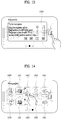
- FIGS. 12 and 13 are diagrams illustrating a different example of a first option provided by a mobile device according to one embodiment of the present invention.
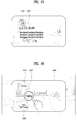
- FIGS. 14 and 15 are diagrams illustrating a further different example of a first option provided by a mobile device according to one embodiment of the present invention.
- the mobile device selectively provide a user with one selected from the group consisting of a first function (tips and guide) shown in FIG. 12 , a second function (adjustment) shown in FIG. 13 and a third function (photographer) shown in FIG. 14 and FIG. 15 .
- a first function tips and guide
- a second function adjustment
- a third function photographer
- the mobile device analyzes information on a location at which the mobile device is currently located and environment information and identifies capturing subject information by analyzing an image in a preview. Subsequently, the mobile device displays a message 1210 for guiding optimized camera setting information via information recognized from weather information, information recognized by an illumination sensor, and information recognized by a temperature and humidity sensor. In this instance, a user can capture an image on a preview using the optimized camera setting information by simply touching a retry button shown in FIG. 12 . For example, if the mobile device shown in FIG.
- the mobile device displays at least one selected from the group consisting of a message for recommending a wide angle mode configuration, a message for recommending a change of an ISO value after brightness and humidity information are identified through an illumination sensor and a temperature and humidity information, and a message for guiding a tip of using a flash after a message or a picture is analyzed and it is determined as a backlight.
- the mobile device displays a message 1310 for comparing original camera setting information of a currently captured picture with the optimized camera setting information automatically recognized by a camera mentioned earlier in FIG. 12 .
- a user can check an image change in real time by operating a controller in a message 1310 shown in FIG. 13 . If the user touches a retry button, the controller can reenter a capturing mode based on finally adjusted camera setting information. Moreover, outputting both a picture captured by the original camera setting information and a picture captured by the optimized setting value on a single screen at the same time also belongs to the scope of the present invention.
- the mobile device analyzes a location and environment and displays a picture of a professional taken in environment similar to the environment analyzed by the mobile device. For example, if information indicating that a plurality of pictures are taken by a specific first professional photographer 1410 at a location at which the mobile device is currently located is stored in an internal memory or an external memory, the mobile device displays samples 1411/1412/1413/1414 of the pictures taken by the specific first professional photographer 1410.
- the mobile device displays samples 1421/1422/1423/1424 of pictures taken by the second specific professional photographer 1420.
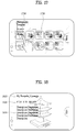
- a specific professional photographer or a picture sample shown in FIG. 14 is selected, as shown in FIG. 15 (in this instance, assume that the first professional photographer 1410 shown in FIG. 14 is selected), a message for guiding camera setting information 1520 mainly used by the specific professional photographer 1510 is output. If a try button shown in FIG. 15 is touched, setting information is automatically changed according to the camera setting information mainly used by the specific professional photographer 1510 and a camera capturing mode is initiated.
- FIGS. 16 and 17 are diagrams illustrating an example of a second option provided by a mobile device according to one embodiment of the present invention.
- a template described in the following corresponds to an image including camera setting information. The image is designated to automatically change a capturing setting value when a picture is captured in a professional mode. According to one embodiment of the present invention, it can select a template and separately manage a template.
- the basic information 1810 includes information on a location at which the template is captured or a title
- the camera setting information 1820 includes an aperture value (F), a shutter value (S) and an ISO value.
- the guide message 1830 includes a guide message such as "Take a picture by increasing resolution of a camera and reducing shutter speed at night. You can take a picture by making a trajectory of light to be exposed. Please be cautious hand shaking when taking a picture".
- a try button shown in FIG. 18 if touched, as shown in FIG. 19 , it may enter a capturing mode and camera setting information is automatically changed to the camera setting information of the template.
- a template drawer 1920 is temporarily displayed.
- the template drawer 1920 includes not only the selected template but also different templates 1921/1922/1923/1924/1925/1926.
- FIGS. 22 to 24 are diagrams illustrating a different example of storing a template stored by a mobile device according to one embodiment of the present invention.
- a specific picture 2210 includes camera setting information 2230
- an indicator 2220 configured to identify the camera setting information is displayed together.
- FIG. 23 if a user 2310 selects (e.g., long touch) the indicator, as shown in FIG. 24 , two menus are provided to the user.
- a first menu 2410 provide the user with a function of adding a selected picture to a template and a second menu 2420 provides the user with a function of immediately entering a capturing mode according to camera setting information of the selected picture.
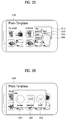
- FIGS. 25 and 26 are diagrams illustrating an example of sharing a template shared by a mobile device according to one embodiment of the present invention.
- a solution enabling a user to more quickly and easily share a template with other users is explained.
- FIG. 25 if a specific template 2500 is selected, 4 menus are provided to a user.
- a first menu 2510 provide the user with a function of sharing the selected specific template with a different device
- a second menu 2520 provides the user with a function (e.g., displaying at home screen) of generating a shortcut for the selected specific template
- a third menu 2530 provides the user with a function of deleting the selected specific template
- a fourth menu 2540 provides the user with a function of changing a scheme of viewing the selected specific template.
- a first menu 2610 corresponds to a sharing scheme via a message
- a second menu 2620 corresponds to a sharing scheme via SNS
- a third menu 2630 corresponds to a sharing scheme via e-mail.
- a sharing scheme e.g., message
- an image of a template and camera setting information are automatically input as a text message. This will be described in the following with reference to FIG. 27 to FIG. 29 .
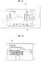
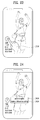
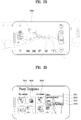
- FIGS. 27 to 29 are diagrams illustrating a different example of sharing a template shared by a mobile device according to one embodiment of the present invention.
- FIG. 27 shows a mobile device to which embodiment of the present invention is not applied
- FIG. 28 to FIG. 29 show a mobile device to which the embodiment of the present invention is applied.
- the mobile device to which the embodiment of the present invention is not applied receives a template by a text message, as shown in FIG. 27 , an image 2710 of the template, camera setting information 2720 applied to the template, a more specifically guiding message, and URL information 2730 capable of downloading the embodiment of the present invention are displayed.
- the mobile device to which the embodiment of the present invention is applied receives a template by a text message, as shown in FIG. 28 , an image 2810 of the template, camera setting information 2820 applied to the template and a camera shortcut button 2830 are displayed.
- the user can take a picture of a style (camera setting information) identical to a style of the template 2810 by simply selecting the button 2830.
- it can immediately execute a professional mode. Since both cases are satisfied at the same time, the present invention has an enhanced technical effect compared to a related art in the aspect of compatibility.
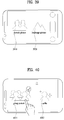
- FIGS. 30 to 32 are diagrams illustrating a process of promptly accessing a templet accessed by a mobile device according to one embodiment of the present invention.
- a plurality of templates 3010/3020/3030 are displayed.
- 4 menus 3031/3032/3033/3034 are displayed.
- a second menu 3032 is selected, as shown in FIG. 31 , the selected specific template 3110 is automatically generated on a home screen.
- 3 selectable menus 3210/3220/3230 are displayed in the vicinity of the specific template 3200.
- a first menu 3210 executes a camera mode while camera setting information identical to camera setting information of the selected specific template is applied.
- a second menu 3220 provides a user with a preview of the selected specific template. In particular, the selected specific template is displayed on a whole screen.
- a third menu 3230 provides the user with a function of sharing the camera setting information of the selected specific template with a different device.
- FIGS. 33 and 34 are diagrams illustrating a process of managing a plurality of templets managed by a mobile device according to one embodiment of the present invention.
- templates are displayed by being grouped according to a category.
- a first group 3310 consists of pictures captured by a user of a mobile device
- a second group 3320 consists of pictures received from a user of a different mobile device
- a third group 3330 consists of pictures downloaded from a web.
- the pictures of the third group can be downloaded or shared from a specific web site.
- a specific template belonging to a random category 3400 is selected, 4 menus 3410/3420/3430/3440 are displayed.
- the 4 menus are explained in the previous drawings.
- a fourth menu 3440 it can change an arrangement scheme of the template.
- the controller can change an arrangement scheme or a grouping scheme based on a person making the template or a category (e.g., food, scenery, person, etc.) of a picture.
- the menus can be applied in a unit of a group (category) to which a template belongs thereto rather than a specific template. This can also be one characteristic of the present invention.
- FIGS. 35 to 38 are diagrams illustrating a process of generating a specific mode for camera capturing generated by a mobile device according to one embodiment of the present invention.
- a method of setting a professional mode by recalling camera setting information on a specific picture of a gallery via a so-called split function is explained in the following.
- FIG. 35 when a user selects a specific object 3511 from a preview screen 3510, as shown in FIG. 36 , the user enters a gallery 3610 and selects a picture 3611 of a style preferred by the user from the gallery.
- camera setting value of the selected picture 3611 is displayed on the top 3700 of a preview screen.
- FIG. 38 the camera setting value 3800 and an image 3810 corresponding to the camera setting value are displayed in a new mode.
- the user can take a picture of a preview image with the corresponding camera setting value 3800 by simply selecting the image 3810, thereby enhancing speed.
- FIGS. 39 to 41 are diagrams illustrating an example of a process of recommending a capturing mode according to location information recommended by a mobile device according to one embodiment of the present invention.
- a user should manually change camera setting values according to surrounding environment.
- a camera setting value is automatically changed based on location information (GPS, POI), time information, weather information, schedule information, web information and the like. Relevant information is stored in a memory in advance in a database form.
- GPS Globalstar, POI
- time information time information
- weather information weather information
- schedule information web information and the like.
- Relevant information is stored in a memory in advance in a database form.
- FIG. 39 to FIG. 41 assume that a user of a mobile device is located at the outside of a building. For example, assume that the user executes a camera at Dulle-gil in Jeju Island. First of all, since GPS is smoothly received, the mobile device recognizes it as the user is located at the outside of a building. As shown in FIG. 39 , the mobile device provides the user with a screen capable of selecting one of a portrait picture mode 3910 and a landscape picture mode 3920. If the user touches an area except areas of the two modes, picture capturing is initiated in a normal mode. In this instance, the normal mode indicates that picture capturing is performed with an original camera setting value of which a camera setting value is not changed.
- a camera setting value is automatically changed to a camera setting value appropriate for the portrait picture mode and then picture capturing is performed.
- a function capable of selecting either a group picture mode 4011 or a selfie picture mode 4012 is provided. If the group picture mode 4011 is selected, for example, a timer is automatically set.
- a camera setting value is automatically changed to a camera setting value appropriate for the landscape picture mode and then picture capturing is performed.
- a function capable of selecting a panorama mode 4110 can be additionally provided.
- FIGS. 42 and 43 are diagrams illustrating a different example of a process of recommending a capturing mode according to location information recommended by a mobile device according to one embodiment of the present invention.
- FIG. 39 to FIG. 41 it is assumed that the user of the mobile device executes the camera while staying at the outside of a building, e.g., at Dulle-gil in Jeju Island.
- FIG. 42 and FIG. 43 described in the following assume that the user of the mobile device executes the camera while staying at the inside of a building, e.g., at the inside of a restaurant.
- the mobile device recognizes it as the user is located at the inside of a building. As shown in FIG. 42 , the mobile device provides the user with a screen capable of selecting one of a portrait picture mode 4210 and a food picture mode 4220. Moreover, a camera setting value is automatically changed according to internal lightning of the restaurant and the like recognized by the camera. Meanwhile, since the portrait picture mode is mentioned earlier in the previous drawing, explanation on the portrait picture mode is omitted at this time.
- a camera setting value is automatically changed to a camera setting value appropriate for the food picture mode and then picture capturing is performed.
- a preview 4300 corresponds to an example of an image of which the camera setting value is changed to the camera setting value appropriate for the food picture mode.
- the present invention provides a user with a technology capable of easily accessing a camera function of high performance.
- the present invention implements simple options for capturing a picture similar to a picture taken by a professional using various GUIs.
- the present invention provides a user with a solution capable of more promptly sharing information on a picture captured by a specific camera setting condition with other users.
Landscapes
- Engineering & Computer Science (AREA)
- Signal Processing (AREA)
- Multimedia (AREA)
- Human Computer Interaction (AREA)
- Computer Networks & Wireless Communication (AREA)
- Telephone Function (AREA)
- User Interface Of Digital Computer (AREA)
- Studio Devices (AREA)
Applications Claiming Priority (1)
| Application Number | Priority Date | Filing Date | Title |
|---|---|---|---|
| KR1020150123481A KR20170027052A (ko) | 2015-09-01 | 2015-09-01 | 모바일 디바이스 및 그 제어 방법 |
Publications (1)
| Publication Number | Publication Date |
|---|---|
| EP3139590A1 true EP3139590A1 (en) | 2017-03-08 |
Family
ID=56081211
Family Applications (1)
| Application Number | Title | Priority Date | Filing Date |
|---|---|---|---|
| EP16162796.3A Ceased EP3139590A1 (en) | 2015-09-01 | 2016-03-30 | Mobile device and method of controlling therefor |
Country Status (5)
| Country | Link |
|---|---|
| US (1) | US10187577B2 (enExample) |
| EP (1) | EP3139590A1 (enExample) |
| KR (1) | KR20170027052A (enExample) |
| CN (1) | CN106488109A (enExample) |
| FR (1) | FR3040501B1 (enExample) |
Cited By (1)
| Publication number | Priority date | Publication date | Assignee | Title |
|---|---|---|---|---|
| US12417480B2 (en) | 2022-09-30 | 2025-09-16 | Motorola Mobility Llc | Personalized product recommendations based on an itinerary |
Families Citing this family (20)
| Publication number | Priority date | Publication date | Assignee | Title |
|---|---|---|---|---|
| US9626747B2 (en) | 2012-04-24 | 2017-04-18 | Apple Inc. | Image enhancement and repair using sample data from other images |
| US9854156B1 (en) | 2016-06-12 | 2017-12-26 | Apple Inc. | User interface for camera effects |
| DK180859B1 (en) | 2017-06-04 | 2022-05-23 | Apple Inc | USER INTERFACE CAMERA EFFECTS |
| US10891126B2 (en) * | 2017-09-11 | 2021-01-12 | Mx Technologies, Inc. | On-device feature and performance testing and adjustment |
| KR102061787B1 (ko) | 2017-11-29 | 2020-01-03 | 삼성전자주식회사 | 이미지를 촬영하는 전자 장치 및 이미지 표시 방법 |
| US11722764B2 (en) | 2018-05-07 | 2023-08-08 | Apple Inc. | Creative camera |
| KR102597680B1 (ko) * | 2018-06-07 | 2023-11-03 | 삼성전자주식회사 | 맞춤형 화질 이미지를 제공하는 전자 장치 및 그 제어 방법 |
| DK201870623A1 (en) | 2018-09-11 | 2020-04-15 | Apple Inc. | USER INTERFACES FOR SIMULATED DEPTH EFFECTS |
| US11128792B2 (en) | 2018-09-28 | 2021-09-21 | Apple Inc. | Capturing and displaying images with multiple focal planes |
| US11321857B2 (en) | 2018-09-28 | 2022-05-03 | Apple Inc. | Displaying and editing images with depth information |
| JP7171406B2 (ja) | 2018-12-12 | 2022-11-15 | キヤノン株式会社 | 電子機器及びその制御方法 |
| CN109862257A (zh) * | 2018-12-25 | 2019-06-07 | 努比亚技术有限公司 | 图像快速处理方法、终端及计算机可读存储介质 |
| US11706521B2 (en) | 2019-05-06 | 2023-07-18 | Apple Inc. | User interfaces for capturing and managing visual media |
| US11770601B2 (en) | 2019-05-06 | 2023-09-26 | Apple Inc. | User interfaces for capturing and managing visual media |
| US11039074B1 (en) | 2020-06-01 | 2021-06-15 | Apple Inc. | User interfaces for managing media |
| US11212449B1 (en) * | 2020-09-25 | 2021-12-28 | Apple Inc. | User interfaces for media capture and management |
| US11778339B2 (en) | 2021-04-30 | 2023-10-03 | Apple Inc. | User interfaces for altering visual media |
| US12112024B2 (en) * | 2021-06-01 | 2024-10-08 | Apple Inc. | User interfaces for managing media styles |
| CN114500844A (zh) * | 2022-01-28 | 2022-05-13 | 维沃移动通信有限公司 | 拍摄方法、装置和电子设备 |
| US20240373120A1 (en) | 2023-05-05 | 2024-11-07 | Apple Inc. | User interfaces for controlling media capture settings |
Citations (6)
| Publication number | Priority date | Publication date | Assignee | Title |
|---|---|---|---|---|
| US20070171282A1 (en) * | 2006-01-18 | 2007-07-26 | Casio Computer Co., Ltd. | Camera apparatus and imaging method |
| US20110267492A1 (en) * | 2010-04-29 | 2011-11-03 | Prentice Wayne E | Indoor/outdoor scene detection using gps |
| US20130076918A1 (en) * | 2011-09-23 | 2013-03-28 | Hyungshin PARK | Method for controlling camera using terminal and terminal thereof |
| US20130329111A1 (en) * | 2012-06-08 | 2013-12-12 | Samsung Electronics Co., Ltd. | Contextual help guide |
| US20150189171A1 (en) * | 2013-12-30 | 2015-07-02 | Samsung Electronics Co., Ltd. | Method and electronic apparatus for sharing photographing setting values, and sharing system |
| US20150189164A1 (en) * | 2013-12-27 | 2015-07-02 | Samsung Electronics Co Ltd | Electronic apparatus having a photographing function and method of controlling the same |
Family Cites Families (5)
| Publication number | Priority date | Publication date | Assignee | Title |
|---|---|---|---|---|
| US20060187230A1 (en) * | 2005-01-31 | 2006-08-24 | Searete Llc | Peripheral shared image device sharing |
| KR100780438B1 (ko) * | 2006-08-22 | 2007-11-29 | 삼성전자주식회사 | 휴대용 단말기에서 카메라의 촬영정보를 설정하는 방법 및장치 |
| US8477228B2 (en) | 2008-06-30 | 2013-07-02 | Verizon Patent And Licensing Inc. | Camera data management and user interface apparatuses, systems, and methods |
| US8675084B2 (en) | 2009-09-04 | 2014-03-18 | Apple Inc. | Systems and methods for remote camera control |
| WO2016017987A1 (en) * | 2014-07-31 | 2016-02-04 | Samsung Electronics Co., Ltd. | Method and device for providing image |
-
2015
- 2015-09-01 KR KR1020150123481A patent/KR20170027052A/ko not_active Withdrawn
-
2016
- 2016-01-27 US US15/007,917 patent/US10187577B2/en not_active Expired - Fee Related
- 2016-03-18 CN CN201610157850.1A patent/CN106488109A/zh not_active Withdrawn
- 2016-03-30 FR FR1652715A patent/FR3040501B1/fr not_active Expired - Fee Related
- 2016-03-30 EP EP16162796.3A patent/EP3139590A1/en not_active Ceased
Patent Citations (6)
| Publication number | Priority date | Publication date | Assignee | Title |
|---|---|---|---|---|
| US20070171282A1 (en) * | 2006-01-18 | 2007-07-26 | Casio Computer Co., Ltd. | Camera apparatus and imaging method |
| US20110267492A1 (en) * | 2010-04-29 | 2011-11-03 | Prentice Wayne E | Indoor/outdoor scene detection using gps |
| US20130076918A1 (en) * | 2011-09-23 | 2013-03-28 | Hyungshin PARK | Method for controlling camera using terminal and terminal thereof |
| US20130329111A1 (en) * | 2012-06-08 | 2013-12-12 | Samsung Electronics Co., Ltd. | Contextual help guide |
| US20150189164A1 (en) * | 2013-12-27 | 2015-07-02 | Samsung Electronics Co Ltd | Electronic apparatus having a photographing function and method of controlling the same |
| US20150189171A1 (en) * | 2013-12-30 | 2015-07-02 | Samsung Electronics Co., Ltd. | Method and electronic apparatus for sharing photographing setting values, and sharing system |
Cited By (1)
| Publication number | Priority date | Publication date | Assignee | Title |
|---|---|---|---|---|
| US12417480B2 (en) | 2022-09-30 | 2025-09-16 | Motorola Mobility Llc | Personalized product recommendations based on an itinerary |
Also Published As
| Publication number | Publication date |
|---|---|
| FR3040501B1 (fr) | 2020-10-02 |
| CN106488109A (zh) | 2017-03-08 |
| KR20170027052A (ko) | 2017-03-09 |
| US20170064205A1 (en) | 2017-03-02 |
| US10187577B2 (en) | 2019-01-22 |
| FR3040501A1 (enExample) | 2017-03-03 |
Similar Documents
| Publication | Publication Date | Title |
|---|---|---|
| US10187577B2 (en) | Mobile device and method of controlling therefor | |
| US10219026B2 (en) | Mobile terminal and method for playback of a multi-view video | |
| US10348972B2 (en) | Mobile terminal and method of controlling therefor | |
| EP3094080B1 (en) | Mobile terminal | |
| US10664158B2 (en) | Mobile terminal and method for controlling the same | |
| EP3128407B1 (en) | Mobile terminal and method for controlling the same | |
| US10185429B2 (en) | Mobile device, wearable device and method of controlling each device | |
| EP2966561B1 (en) | Mobile terminal equipped with touch screen and method of controlling therefor | |
| US10531262B2 (en) | Mobile terminal | |
| US9710099B2 (en) | Mobile terminal and method for controlling the same | |
| EP3096506A2 (en) | Watch-type mobile terminal and method of controlling therefor | |
| EP3079134A1 (en) | Mobile terminal and method for controlling the same | |
| US9454301B2 (en) | Mobile terminal controlled by at least one touch and method of controlling therefor | |
| US10348970B2 (en) | Mobile terminal and method of operating the same | |
| US11645644B2 (en) | Mobile terminal | |
| EP2998878A2 (en) | Mobile terminal and method of controlling therefor | |
| US10241737B2 (en) | Mobile terminal and method for controlling the same | |
| US20180181283A1 (en) | Mobile terminal and method for controlling the same | |
| US9516158B2 (en) | Mobile terminal and controlling method thereof | |
| US10375380B2 (en) | Mobile terminal and operating method thereof |
Legal Events
| Date | Code | Title | Description |
|---|---|---|---|
| PUAI | Public reference made under article 153(3) epc to a published international application that has entered the european phase |
Free format text: ORIGINAL CODE: 0009012 |
|
| STAA | Information on the status of an ep patent application or granted ep patent |
Free format text: STATUS: REQUEST FOR EXAMINATION WAS MADE |
|
| 17P | Request for examination filed |
Effective date: 20160330 |
|
| AK | Designated contracting states |
Kind code of ref document: A1 Designated state(s): AL AT BE BG CH CY CZ DE DK EE ES FI FR GB GR HR HU IE IS IT LI LT LU LV MC MK MT NL NO PL PT RO RS SE SI SK SM TR |
|
| AX | Request for extension of the european patent |
Extension state: BA ME |
|
| RBV | Designated contracting states (corrected) |
Designated state(s): AL AT BE BG CH CY CZ DE DK EE ES FI FR GB GR HR HU IE IS IT LI LT LU LV MC MK MT NL NO PL PT RO RS SE SI SK SM TR |
|
| STAA | Information on the status of an ep patent application or granted ep patent |
Free format text: STATUS: EXAMINATION IS IN PROGRESS |
|
| 17Q | First examination report despatched |
Effective date: 20170726 |
|
| STAA | Information on the status of an ep patent application or granted ep patent |
Free format text: STATUS: THE APPLICATION HAS BEEN REFUSED |
|
| 18R | Application refused |
Effective date: 20181029 |