EP3139396A1 - Contact switching device - Google Patents
Contact switching device Download PDFInfo
- Publication number
- EP3139396A1 EP3139396A1 EP16184426.1A EP16184426A EP3139396A1 EP 3139396 A1 EP3139396 A1 EP 3139396A1 EP 16184426 A EP16184426 A EP 16184426A EP 3139396 A1 EP3139396 A1 EP 3139396A1
- Authority
- EP
- European Patent Office
- Prior art keywords
- movable
- contact
- yoke
- fixed
- holder
- Prior art date
- Legal status (The legal status is an assumption and is not a legal conclusion. Google has not performed a legal analysis and makes no representation as to the accuracy of the status listed.)
- Granted
Links
Images







Classifications
-
- H—ELECTRICITY
- H01—ELECTRIC ELEMENTS
- H01H—ELECTRIC SWITCHES; RELAYS; SELECTORS; EMERGENCY PROTECTIVE DEVICES
- H01H51/00—Electromagnetic relays
- H01H51/29—Relays having armature, contacts, and operating coil within a sealed casing
-
- H—ELECTRICITY
- H01—ELECTRIC ELEMENTS
- H01H—ELECTRIC SWITCHES; RELAYS; SELECTORS; EMERGENCY PROTECTIVE DEVICES
- H01H9/00—Details of switching devices, not covered by groups H01H1/00 - H01H7/00
- H01H9/30—Means for extinguishing or preventing arc between current-carrying parts
- H01H9/44—Means for extinguishing or preventing arc between current-carrying parts using blow-out magnet
- H01H9/443—Means for extinguishing or preventing arc between current-carrying parts using blow-out magnet using permanent magnets
-
- H—ELECTRICITY
- H01—ELECTRIC ELEMENTS
- H01H—ELECTRIC SWITCHES; RELAYS; SELECTORS; EMERGENCY PROTECTIVE DEVICES
- H01H50/00—Details of electromagnetic relays
- H01H50/54—Contact arrangements
- H01H50/546—Contact arrangements for contactors having bridging contacts
-
- H—ELECTRICITY
- H01—ELECTRIC ELEMENTS
- H01H—ELECTRIC SWITCHES; RELAYS; SELECTORS; EMERGENCY PROTECTIVE DEVICES
- H01H51/00—Electromagnetic relays
- H01H51/02—Non-polarised relays
- H01H51/04—Non-polarised relays with single armature; with single set of ganged armatures
- H01H51/06—Armature is movable between two limit positions of rest and is moved in one direction due to energisation of an electromagnet and after the electromagnet is de-energised is returned by energy stored during the movement in the first direction, e.g. by using a spring, by using a permanent magnet, by gravity
-
- H—ELECTRICITY
- H01—ELECTRIC ELEMENTS
- H01H—ELECTRIC SWITCHES; RELAYS; SELECTORS; EMERGENCY PROTECTIVE DEVICES
- H01H1/00—Contacts
- H01H1/50—Means for increasing contact pressure, preventing vibration of contacts, holding contacts together after engagement, or biasing contacts to the open position
- H01H1/54—Means for increasing contact pressure, preventing vibration of contacts, holding contacts together after engagement, or biasing contacts to the open position by magnetic force
- H01H2001/545—Means for increasing contact pressure, preventing vibration of contacts, holding contacts together after engagement, or biasing contacts to the open position by magnetic force having permanent magnets directly associated with the contacts
-
- H—ELECTRICITY
- H01—ELECTRIC ELEMENTS
- H01H—ELECTRIC SWITCHES; RELAYS; SELECTORS; EMERGENCY PROTECTIVE DEVICES
- H01H2205/00—Movable contacts
- H01H2205/016—Separate bridge contact
-
- H—ELECTRICITY
- H01—ELECTRIC ELEMENTS
- H01H—ELECTRIC SWITCHES; RELAYS; SELECTORS; EMERGENCY PROTECTIVE DEVICES
- H01H2213/00—Venting
-
- H—ELECTRICITY
- H01—ELECTRIC ELEMENTS
- H01H—ELECTRIC SWITCHES; RELAYS; SELECTORS; EMERGENCY PROTECTIVE DEVICES
- H01H2223/00—Casings
- H01H2223/002—Casings sealed
-
- H—ELECTRICITY
- H01—ELECTRIC ELEMENTS
- H01H—ELECTRIC SWITCHES; RELAYS; SELECTORS; EMERGENCY PROTECTIVE DEVICES
- H01H2235/00—Springs
- H01H2235/01—Spiral spring
Definitions
- the present invention relates to a contact switching device, and particularly relates to a contact switching device suitable for a power loading relay, an electromagnetic switch, or the like.
- a pair of through holes 61 a is provided on the upper surface of a container 61 made of a heat-resistant material such as ceramic. Then, fixed terminals 33, 33 are respectively inserted and brazed into the pair of through holes 61a. Further, a yoke body 63 is located between the pair of fixed terminals 33, 33, and fixed to the inner upper surface of the container 61.
- the yoke body 63 has a substantially parallelepiped shape and is made of a magnetic material such as soft ion.
- the yoke body 63 needs to be fixed, for example by brazing, to the inner upper surface of the box-shaped container 61.
- the fixing operation requires proficient skills and an assembly operation takes time, resulting in low productivity and high manufacturing cost.
- an object of the present invention is to provide a contact switching device which has high productivity and in which operation characteristics hardly vary.
- a contact switching device includes: an electromagnetic unit; a holder mounted in the electromagnetic unit; a movable shaft having one end inserted through the inside of the holder and the other end inserted through the inside of the electromagnetic unit, and supported reciprocatably in a direction of an axis center; a movable contact piece provided at the one end of the movable shaft in the holder and housed in the holder, while having a pair of movable contacts disposed on the front surface on the opposite side to the electromagnetic unit in the axis center direction of the movable shaft; a movable yoke disposed on the rear surface of the movable contact piece on the electromagnetic unit side in the axis center direction of the movable shaft, and assembled to the one end of the movable shaft in the holder; a pair of fixed contacts disposed in the holder and facing the pair of movable contacts in a contactable and separable manner; and a fixed yoke located between the pair of fixed contacts, and supported as a result of placing
- the contact switching device is configured such that, at the time of excitation of the electromagnetic unit, the movable shaft moves in a direction from the electromagnetic unit to the holder along the axis center direction, that a magnetic circuit is formed of the fixed yoke and the movable yoke due to a magnetic field generated by a current that flows into the movable contact piece as a result of the pair of movable contacts coming into contact with the pair of fixed contacts, and that the movable yoke is magnetically attracted to the fixed yoke.
- the fixed yoke is supported by the holder as a result of placing both ends of the fixed yoke in the holder, thereby eliminating the need to fix the fixed yoke by brazing or the like to the inner upper surface of the box-shaped container as is done in the conventional example.
- the assembly operation is simply performed, leading to high productivity and low manufacturing cost.
- both ends of the fixed yoke only have to be placed in the holder, it is possible to obtain a contact switching device where an assembly error hardly occurs and the operation characteristics hardly vary.
- the sealed electromagnetic relay is configured to include at least an electromagnetic unit 60, a holder 35, a movable shaft 43, a movable contact piece 49, a movable yoke 48, a pair of fixed contacts 33a, and a fixed yoke 51.
- a contact mechanism unit 30 and the electromagnetic unit 60 are incorporated into a housing formed by assembling an outer cover 20 to a case 10.
- the case 10 is an insulating resin molded article in a substantially quadrilateral box shape.
- a set of notches 11 is formed on one side of the opening edge of the case 10. Further, at both ends of the opening edges on the facing lateral surfaces of the case 10, a total of two pairs of locking holes 12 are provided.
- the outer cover 20 has insulating properties and the shape of a quadrilateral box with a plane shape capable of covering the opening of the case 10.
- two pairs of locking claws 24 that are locked to two pairs of locking holes 12 in the case 10 are extended from the opening edges of the facing lateral surfaces.
- the contact mechanism unit 30 is configured to include the holder 35, a cylindrical fixed iron core 42, the movable shaft 43, a movable iron core 45, and the movable contact piece 49, and is incorporated into a sealed space formed of a metal cylindrical flange 31, a ceramic plate 32, a platy first yoke 41, and a bottomed cylinder 46.
- the metal cylindrical flange 31 has a substantially quadrilateral box shape formed by pressing a metal plate.
- the ceramic plate 32 is then brazed to the outer peripheral edge of the upper end of the metal cylindrical flange 31. Further, the outer peripheral edge of the lower end of the metal cylindrical flange 31 is integrated, by welding, into the platy first yoke 41 described later.
- the ceramic plate 32 has a plane shape that can be brazed to the opening edge of the upper end of the metal cylindrical flange 31. Further, the ceramic plate 32 is provided with terminal holes 32a, 32a, and a gas vent hole 32b. In the ceramic plate 32, a metal layer, not shown, is formed at each of the opening edge of the terminal hole 32a and the opening edge of the gas vent hole 32b. Then, as shown in Fig. 10 , a fixed contact terminal 33, having the fixed contact 33a fixed to its lower end, is brazed to the terminal hole 32a of the ceramic plate 32. Accordingly, the fixed contact 33a is disposed in the holder 35 and faces a movable contact 49a in a contactable and openable manner. Further, as shown in Fig. 11 , a gas vent pipe 34 is brazed to the gas vent hole 32b in the ceramic plate 32.
- the holder 35 is mounted in the electromagnetic unit 60, is formed of heat-resistant insulating material having a quadrilateral box shape, and is housed in the metal cylindrical flange 31 ( Fig. 10 ). As shown in Fig. 15 , a pocket part 35a capable of holding a permanent magnet 36 is formed on each of the facing outside surfaces on both sides of the holder 35. Further, in the center of the bottom surface of the holder 35, a central recess 35b having a planar square shape is provided to be one stage lower than the bottom surface. A cylindrical insulator 35c ( Fig. 10 ) is projecting downward from the center of the central recess 35b.
- the cylindrical insulator 35c insulates the cylindrical fixed iron core 42 and the movable shaft 43 from each other, to thereby prevent these from being welded and integrated.
- a pair of pedestals 35d are respectively provided on bases of the facing inside surfaces of the holder 35.
- the respective pedestals 35d are configured of projections projecting from the bases of the respective inside surfaces of the holder 35, and having the same heights.
- a slit 35e for supporting a position regulating plate 37 described later is provided between each of the pedestals 35d and the central recess 35b.
- a recess 35f in which an arc extinguishing piece 38 described later can be disposed, is provided between the central recess 35b and the pocket part 35a in the holder 35.
- position regulating ribs 35g, 35g are projecting from both longitudinal sides of the movable contact piece 49 of each of the pedestals 35d. Then, as shown in Fig. 2 , the holder 35 is placed on a platy first yoke 41 described later via a rectangular platy spacer 39 and a set of quadrilateral platy buffer materials 40.
- the position regulating plate 37 is made up of an elastic metal plate with a substantially rectangular front surface, and both side edges thereof are cut and raised to form elastic claws.
- the position regulating plate 37 is pressed into the slit 35e of the holder 35, to be pressed to be in contact with the movable yoke 48 in the holder 35.
- the position regulating plate 37 then makes the pressing force act on the movable contact piece 49 via the movable yoke 48, to regulate the spinning of the movable contact piece 49 and the movable yoke 48 described later.
- the arc extinguishing piece 38 has a gate shape (U-shape) in a cross section which is formed by performing press working on thin plate metal. Then, the arc extinguishing piece 38 is installed in a recess 35f ( Fig. 15 ) of the holder 35 so as to quench and efficiently extinguish the arc generated at the time of switching the contacts.
- the buffer material 40 is a platy body made up of an elastic material.
- the buffer material 40 is sandwiched between the bottom surface of the holder 35 and the platy first yoke 41 covered by the spacer 39.
- the platy first yoke 41 has a plane shape that can be fit to the opening edge of the case 10. Further, a caulking hole 41 a is provided in the center of the platy first yoke 41.
- the platy first yoke 41 is formed by welding and integrating the outer peripheral edge of the lower end of the metal cylindrical flange 31 to the outer peripheral edge of the upper surface of the platy first yoke 41. Further, the upper end of the cylindrical fixed iron core 42 is fixed to the caulking hole 41 a of the platy first yoke 41.
- One end of the movable shaft 43 is inserted through the holder 35, and the other end thereof is inserted through the inside of the electromagnetic unit 60. Meanwhile, the movable shaft 43 is reciprocatably supported in an axis center direction of the movable shaft 43. Specifcally, as shown in Fig. 10 , the movable shaft 43 is slidably inserted into a through hole 42a of the cylindrical fixed iron core 42 in the axis center direction of the movable shaft 43 via the cylindrical insulator 35c of the holder 35. An annular flange part 43a is provided in the upper part of the movable shaft 43. A return spring 44 is inserted through the lower part of the movable shaft 43, and a movable iron core 45 is fixed to the lower end thereof.
- the movable contact piece 49 is provided at one end of the movable shaft 43 and housed in the holder 35. Further, the movable contact piece 49 has a pair of movable contacts 49a, 49a respectively on both ends in a direction intersecting with (e.g., orthogonal to) the axis center direction of the movable shaft 43 (i.e., on the front surface (upper surface) on the opposite side to the electromagnetic unit 60 in the axis center direction of the movable shaft 43). Specifically, as shown in Fig.
- a contact spring 47, the movable yoke 48, and the movable contact piece 49 sequentially inserted through the movable shaft 43 from its upper end, are locked by an annular flange part 45a, and are retained to the movable shaft 43 by a retaining ring 50 fixed to its upper end.
- the movable yoke 48 is disposed on the opposite side to a projecting direction of a pair of movable contacts 49a, 49a provided on the movable contact piece 49 (i.e., on the rear surface (lower surface) of the movable contact piece 49 on the electromagnetic unit 60 side in the axis center direction of the movable shaft 43), and is assembled to one end of the movable shaft 43.
- the movable yoke 48 is obtained by bending and raising both ends of a platy magnetic material 90 degrees, parallelly in the same direction, to form bent-and-raised parts 48a, 48a.
- the movable yoke 48 has a gate shape (U-shape) in a cross section. The movable yoke 48 comes into contact with the lower surface of the movable contact piece 49.
- the movable contact piece 49 has the movable contacts 49a, 49a by projection processing at both longitudinal ends of its upper surface.
- the movable contacts 49a, 49a face the fixed contacts 33a, 33a, respectively, of the fixed contact terminal 33 disposed in the holder 35 in a contactable and separable manner.
- the opening edge of the bottomed cylinder 46 is airtightly joined to the vicinity of the edge of the lower surface of the caulking hole 41 a provided in the platy first yoke 41, the bottomed cylinder 46 housing the movable iron core 45 in the vicinity of its lower end. After the internal air is sucked from the gas vent pipe 34, the pipe is filed with gas and sealed to form a sealed space.
- the fixed yoke 51 is located between the pair of fixed contacts 33a, 33a separately from the pair of fixed contacts 33a, 33a.
- the fixed yoke 51 is supported so as to bridge both longitudinal ends thereof in the holder, the both ends being along a direction intersecting with (e.g., orthogonal to) the axis center direction of the movable shaft 43 and intersecting with (e.g., orthogonal to) the longitudinal direction of the movable contact piece 49.
- a direction intersecting with (e.g., orthogonal to) the axis center direction of the movable shaft 43 and intersecting with (e.g., orthogonal to) the longitudinal direction of the movable contact piece 49 Specifically, as shown in Fig.
- the fixed yoke 51 is a platy magnetic material having a substantially I-shape on a plane, and having a gate shape (U-shape) in a cross section, with projections 51 a projecting at both longitudinal ends so as to be bent at 90 degrees. Further, a longitudinal length dimension of the fixed yoke 51 is longer than a longitudinal length dimension of the movable yoke 48. Hence, the fixed yoke 51 is superimposed on the movable yoke 48 so as to cover the whole of the movable yoke 48 in the longitudinal direction, resulting in a little leakage of a magnetic flux and favorable magnetic efficiency.
- the fixed yoke 51 is bridged with the pair of projections 51 a ( Fig. 16 ) placed on the pair of pedestals 35d of the holder 35 shown in Fig. 8 . Further, as shown in Fig. 17 , the positions of the respective ends of the fixed yoke 51 are regulated by a pair of position regulating ribs 35g, which is disposed on both sides of the adjacent pair of pedestals 35d, 35d, so as not to move in the longitudinal direction of the movable contact piece 49.
- dispersed powder friction powder is dispersed (hereinafter referred to as dispersed powder), the power being generated in association with the contact and opening between the fixed contact 33a and the movable contact 49a.
- dispersed powder the power being generated in association with the contact and opening between the fixed contact 33a and the movable contact 49a.
- the fixed yoke 51 is held by the holder 35 made of resin, with an insulating property ensuring gap 80 formed between the fixed yoke 51 and the ceramic plate 32. Accordingly, even when the dispersed powder is disposed between the fixed contact terminal 33 and the fixed yoke 51, the insulating property ensuring gap 80 is not filled. Hence, the short circuit channel is hardly formed between the fixed contact terminal and the fixed yoke, enabling prevention of deterioration in insulating properties of the contact switching device.
- a lid 52 is an insulating platy body having a plane shape that can be fit to the opening of the holder 35.
- the lid 52 is provided with a through hole 52b between a pair of terminal holes 52a, 52a where the pair of fixed contact terminals 33, 33 are to be inserted.
- An inner cover 53 is an insulating elastic body having a cubic shape capable of covering the metal cylindrical flange 31 brazed with the ceramic plate 32.
- a rubber material that easily absorbs collision sound between the movable contact 49a and the fixed contact 33a may be used.
- a through hole 53b through which the gas vent pipe 34 penetrates is provided between a pair of terminal holes 53a, 53a which is provided on the ceiling surface of the inner cover 53 and through which the fixed contact terminals 33 respectively penetrate.
- the electromagnetic unit 60 is formed by winding a coil 61 around a trunk part 62a of an insulating spool 62.
- An upper-side flange part 62b and a lower-side flange part 62c are provided on both axial ends of the trunk part 62a.
- Coil terminals 63, 64 are respectively pressed and fixed into a pair of slits 62d, 62d provided in the upper-side flange part 62b.
- a lead wire of the coil 61 is tied to tying parts 63a, 64a of the coil terminals 63, 64, and soldered thereto.
- terminal parts 63b, 64b thereof laterally project.
- the bottomed cylinder 46 is inserted through a through hole 62e provided in the trunk part 62a of the spool 62. Subsequently, the lower end of the bottomed cylinder 46 is fit to a fitting hole 65a of a second yoke 65. Then, the upper ends of both arms 65b, 65b of the second yoke 65 are respectively engaged and fixed to both ends of the platy first yoke 41. Examples of a method for the fixing include caulking, pressing-in, welding, and the like. As a result of the fixing, the electromagnetic unit 60 and the contact mechanism unit 30 are integrated.
- the fixed yoke 51 and the movable yoke 48 do not come into direct contact with each other, and a magnetic circuit is made while a predetermined contact reliability ensuring gap 90 is held. This is for ensuring the contact reliability by the contact reliability ensuring gap 90.
- it is configured such that a facing distance between the fixed yoke 51 and the movable yoke 48 facing each other is larger than an inter-contact distance between the movable contact 49a and the fixed contact 33a.
- the fixed yoke 51 placed and bridged between the pedestals 35d, 35d of the holder 35 is fixed via the ceramic plate 32 provided with the lid 52 and the fixed contact 33a.
- the movable yoke 48 is in contact with the lower surface of the movable contact piece 49 provided with the movable contact 49a. Accordingly, when the movable contact 49a comes into contact with the fixed contact 33a, the contact reliability ensuring gap 90 between the fixed yoke 51 and the movable yoke 48 can be formed with high dimensional accuracy.
- the fixed yoke 51 is supported by the holder 35 as a result of placing a pair of projections 51 a ( Fig. 16 ) of the fixed yoke 51 in the holder 35, thereby eliminating the need to fix the fixed yoke by brazing to the inner upper surface of the box-shaped container as is done in the conventional example.
- the assembly operation is simply performed, leading to high productivity and low manufacturing cost.
- both ends of the fixed yoke only have to be placed in the holder, it is possible to obtain a contact switching device where an assembly error hardly occurs and the operation characteristics hardly vary.
- a pair of projections 51a of the fixed yoke 51 are placed on a pair of pedestals 35d, thereby facilitating the assembly operation for the fixed yoke.
- the longitudinal length dimension of the fixed yoke may be made longer than the longitudinal length dimension of the movable yoke.
- the fixed yoke is superimposed on the movable yoke so as to cover the whole of the movable yoke in the longitudinal direction, it is possible to obtain a contact switching device with small leakage of a magnetic flux and with favorable magnetic efficiency.
- the facing distance between the facing fixed yoke and movable yoke may be made longer than the inter-contact distance between the movable contact and the fixed contact.
- the movable yoke does not come into contact with the fixed yoke and, hence, the contact between the pair of movable contacts and the pair of fixed contacts is not prevented. Consequently, the contact switching device with high contact reliability can be obtained.
- a gap may be provided so that the fixed yoke does not come into direct contact with the movable yoke when the movable contact comes into contact with the fixed contact.
- the movable yoke does not come into contact with the fixed yoke and, hence, the contact between the pair of movable contacts and the pair of fixed contacts is not prevented. Hence, the contact switching device with high contact reliability can be obtained.
- the movable yoke may be in contact with one surface of the movable contact piece on the opposite side to a projecting direction of the movable contact provided on the movable contact piece.
- the movable contact piece 49 is in contact with the movable yoke 48, magnetic resistance of the magnetic circuit between the made up of the fixed yoke 51 and the movable yoke 48 becomes smaller. Hence, it is possible to obtain a contact switching device having favorable magnetic efficiency and capable of suppressing the electromagnetic repulsive force by large magnetic force.
- the collision force of the movable shaft 43 is absorbed into the buffer material 40 and reduced via the holder 35.
- the movable iron core 45 does not come into contact with the bottom surface of the bottomed cylinder 46.
- collision sound of the movable shaft 43 is absorbed and reduced by the holder 35, the buffer material 40, the cylindrical fixed iron core 42, the inner cover 53, the electromagnetic unit 60, and the like.
- the movable shaft 43 makes a vertical motion in response to a vertical motion of the movable contact piece 49. Also at this time, even when the movable contact piece 49 and the movable yoke 48 are slightly displaced, the movable yoke 48 comes into contact with the position regulating plate 37 pressed into the slit 35e ( Fig. 15 ) of the holder 35 so that the position of the movable yoke 48 is regulated. For this reason, the movable contact piece 49 and the movable yoke 48 do not come into direct contact with the holder 35. As a result, no resin powder is generated and no contact failure occurs. In particular, since the position regulating plate 37 is formed of a metal material, abrasion powder is hardly generated.
- the fixed yoke 51 is held in the holder 35 made up of the insulating material, but this is not restrictive.
- the fixed yoke 51 may be held by way of being connected to the ceramic plate 32 via a ceramic connector 70.
- the insulating property ensuring gap 80 is not filled.
- the short circuit channel is hardly formed between the fixed contact terminal 33 and the fixed yoke 51 via the dispersed powder, enabling prevention of deterioration in insulating properties of the contact switching device.
- the contact switching device according to the present invention is not limited to the foregoing electromagnetic relay, but may naturally be applied to another contact switching device.
Landscapes
- Physics & Mathematics (AREA)
- Electromagnetism (AREA)
- Contacts (AREA)
Description
- The present invention relates to a contact switching device, and particularly relates to a contact switching device suitable for a power loading relay, an electromagnetic switch, or the like.
- In the related art, as a conventional contact switching device, for example as shown in
Fig. 5A ofJP 2012-104356 A container 61 made of a heat-resistant material such as ceramic. Then,fixed terminals yoke body 63 is located between the pair offixed terminals container 61. Theyoke body 63 has a substantially parallelepiped shape and is made of a magnetic material such as soft ion. - When
movable contacts movable contactor 35 come in contact with thefixed contacts movable contactor 35. A holder 81 is thereby attracted to theyoke body 63, to reduce electromagnetic repulsive force that is generated between themovable contact 34 and the fixedcontact 32. As a result, the reduction prevents a decrease in contact pressure, and prevents welding of the movable contact and the fixedcontact 32 in association with an increase in contact resistance. Further, with generation of the electromagnetic repulsive force, themovable contact 34 and the fixedcontact 32 are opened and an arc is generated, thereby preventing the welding of themovable contact 34 and the fixedcontact 32. - However, in the above contact device, the
yoke body 63 needs to be fixed, for example by brazing, to the inner upper surface of the box-shaped container 61. Hence, the fixing operation requires proficient skills and an assembly operation takes time, resulting in low productivity and high manufacturing cost. - Further, in the foregoing assembly operation, an assembly error easily occurs and the high positioning accuracy is hardly achieved, thus causing a problem that operation characteristics easily vary.
- In view of the above problems, an object of the present invention is to provide a contact switching device which has high productivity and in which operation characteristics hardly vary.
- A contact switching device according to the present invention includes: an electromagnetic unit; a holder mounted in the electromagnetic unit; a movable shaft having one end inserted through the inside of the holder and the other end inserted through the inside of the electromagnetic unit, and supported reciprocatably in a direction of an axis center; a movable contact piece provided at the one end of the movable shaft in the holder and housed in the holder, while having a pair of movable contacts disposed on the front surface on the opposite side to the electromagnetic unit in the axis center direction of the movable shaft; a movable yoke disposed on the rear surface of the movable contact piece on the electromagnetic unit side in the axis center direction of the movable shaft, and assembled to the one end of the movable shaft in the holder; a pair of fixed contacts disposed in the holder and facing the pair of movable contacts in a contactable and separable manner; and a fixed yoke located between the pair of fixed contacts, and supported as a result of placing both ends thereof in a longitudinal direction that intersects with the axis center direction of the movable shaft and intersects with a longitudinal direction of the movable contact piece. The contact switching device is configured such that, at the time of excitation of the electromagnetic unit, the movable shaft moves in a direction from the electromagnetic unit to the holder along the axis center direction, that a magnetic circuit is formed of the fixed yoke and the movable yoke due to a magnetic field generated by a current that flows into the movable contact piece as a result of the pair of movable contacts coming into contact with the pair of fixed contacts, and that the movable yoke is magnetically attracted to the fixed yoke.
- According to the present invention, the fixed yoke is supported by the holder as a result of placing both ends of the fixed yoke in the holder, thereby eliminating the need to fix the fixed yoke by brazing or the like to the inner upper surface of the box-shaped container as is done in the conventional example. Hence, the assembly operation is simply performed, leading to high productivity and low manufacturing cost.
- Further, since both ends of the fixed yoke only have to be placed in the holder, it is possible to obtain a contact switching device where an assembly error hardly occurs and the operation characteristics hardly vary.
-
-
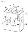
Fig. 1 is an overall perspective view showing a contact switching device according to an embodiment of the present invention; -
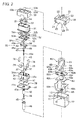
Fig. 2 is an exploded perspective view of the contact switching device shown inFig. 1 ; -
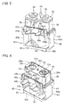
Fig. 3 is a perspective view showing a state where a case and an outer cover are removed from the contact switching device shown inFig. 1 ; -
Fig. 4 is a perspective view showing a state where an inner cover is removed from the perspective view shown inFig. 3 ; -
Fig. 5 is a perspective view showing a state where a metal cylindrical flange is removed from the perspective view shown inFig. 4 ; -
Fig. 6 is a perspective view showing a state where a ceramic plate, a fixed contact terminal, and a gas vent pipe are removed from the perspective view shown inFig. 5 ; -
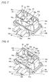
Fig. 7 is a perspective view showing a state where a lid is removed from the perspective view shown inFig. 6 ; -
Fig. 8 is a perspective view showing a state where a fixed yoke is removed from the perspective view shown inFig. 7 ; -
Fig. 9 is a perspective view showing a state where a position regulating plate is removed from the perspective view shown inFig. 8 ; -
Fig. 10 is a front longitudinal sectional view before operation illustrated in the perspective view shown inFig. 3 ; -
Fig. 11 is a lateral longitudinal sectional view before the operation illustrated in the perspective view shown inFig. 3 ; -
Fig. 12 is a front longitudinal sectional view after the operation illustrated in the perspective view shown inFig. 3 ; -
Fig. 13 is a lateral longitudinal sectional view after the operation illustrated in the perspective view shown inFig. 3 ; -
Fig. 14 is an enlarged perspective view of a part of an electromagnetic unit shown inFig. 3 ; -
Fig. 15 is a perspective view of a holder shown inFig. 9 ; -
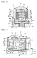
Fig. 16 is a lateral sectional perspective view of a part of the perspective view shown inFig. 4 ; -
Fig. 17 is a front sectional perspective view of a part of the perspective view shown inFig. 4 ; -
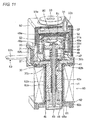
Fig. 18 is a front longitudinal sectional view showing a contact switching device according to another embodiment of the present invention before operation; and -
Fig. 19 is a lateral longitudinal sectional view of the contact switching device ofFig. 18 . - A description will be given of an instance where a contact switching device according to an embodiment of the present invention is applied to a sealed electromagnetic relay, in accordance with the attached drawings of
Figs. 1 to 17 . - The sealed electromagnetic relay according to the embodiment is configured to include at least an
electromagnetic unit 60, aholder 35, amovable shaft 43, amovable contact piece 49, amovable yoke 48, a pair offixed contacts 33a, and afixed yoke 51. Specifically, as shown inFigs. 1 to 5 , acontact mechanism unit 30 and theelectromagnetic unit 60 are incorporated into a housing formed by assembling anouter cover 20 to acase 10. - As shown in
Fig. 2 , thecase 10 is an insulating resin molded article in a substantially quadrilateral box shape. A set ofnotches 11 is formed on one side of the opening edge of thecase 10. Further, at both ends of the opening edges on the facing lateral surfaces of thecase 10, a total of two pairs oflocking holes 12 are provided. - The
outer cover 20 has insulating properties and the shape of a quadrilateral box with a plane shape capable of covering the opening of thecase 10. On both sides of aninsulating partition wall 21 projecting from the center of the upper surface of theouter cover 20,terminal holes tongue pieces 23 which are fit to thenotches 11 of thecase 10 are projecting from one lateral surface of theouter cover 20. Moreover, in theouter cover 20, two pairs oflocking claws 24 that are locked to two pairs oflocking holes 12 in thecase 10 are extended from the opening edges of the facing lateral surfaces. - The
contact mechanism unit 30 is configured to include theholder 35, a cylindricalfixed iron core 42, themovable shaft 43, amovable iron core 45, and themovable contact piece 49, and is incorporated into a sealed space formed of a metalcylindrical flange 31, aceramic plate 32, a platyfirst yoke 41, and a bottomedcylinder 46. - As shown in
Fig. 2 , the metalcylindrical flange 31 has a substantially quadrilateral box shape formed by pressing a metal plate. Theceramic plate 32 is then brazed to the outer peripheral edge of the upper end of the metalcylindrical flange 31. Further, the outer peripheral edge of the lower end of the metalcylindrical flange 31 is integrated, by welding, into the platyfirst yoke 41 described later. - The
ceramic plate 32 has a plane shape that can be brazed to the opening edge of the upper end of the metalcylindrical flange 31. Further, theceramic plate 32 is provided withterminal holes gas vent hole 32b. In theceramic plate 32, a metal layer, not shown, is formed at each of the opening edge of theterminal hole 32a and the opening edge of thegas vent hole 32b. Then, as shown inFig. 10 , afixed contact terminal 33, having thefixed contact 33a fixed to its lower end, is brazed to theterminal hole 32a of theceramic plate 32. Accordingly, the fixedcontact 33a is disposed in theholder 35 and faces amovable contact 49a in a contactable and openable manner. Further, as shown inFig. 11 , agas vent pipe 34 is brazed to thegas vent hole 32b in theceramic plate 32. - The
holder 35 is mounted in theelectromagnetic unit 60, is formed of heat-resistant insulating material having a quadrilateral box shape, and is housed in the metal cylindrical flange 31 (Fig. 10 ). As shown inFig. 15 , apocket part 35a capable of holding apermanent magnet 36 is formed on each of the facing outside surfaces on both sides of theholder 35. Further, in the center of the bottom surface of theholder 35, acentral recess 35b having a planar square shape is provided to be one stage lower than the bottom surface. Acylindrical insulator 35c (Fig. 10 ) is projecting downward from the center of thecentral recess 35b. When an arc is generated, even if a voltage becomes high through a channel of the metalcylindrical flange 31, the platyfirst yoke 41, and the cylindrical fixediron core 42, thecylindrical insulator 35c insulates the cylindrical fixediron core 42 and themovable shaft 43 from each other, to thereby prevent these from being welded and integrated. Further, a pair ofpedestals 35d are respectively provided on bases of the facing inside surfaces of theholder 35. Therespective pedestals 35d are configured of projections projecting from the bases of the respective inside surfaces of theholder 35, and having the same heights. Then, aslit 35e for supporting aposition regulating plate 37 described later is provided between each of thepedestals 35d and thecentral recess 35b. Further, arecess 35f, in which anarc extinguishing piece 38 described later can be disposed, is provided between thecentral recess 35b and thepocket part 35a in theholder 35. Moreover,position regulating ribs movable contact piece 49 of each of thepedestals 35d. Then, as shown inFig. 2 , theholder 35 is placed on a platyfirst yoke 41 described later via arectangular platy spacer 39 and a set of quadrilateralplaty buffer materials 40. - As shown in
Fig. 2 , theposition regulating plate 37 is made up of an elastic metal plate with a substantially rectangular front surface, and both side edges thereof are cut and raised to form elastic claws. Theposition regulating plate 37 is pressed into theslit 35e of theholder 35, to be pressed to be in contact with themovable yoke 48 in theholder 35. Theposition regulating plate 37 then makes the pressing force act on themovable contact piece 49 via themovable yoke 48, to regulate the spinning of themovable contact piece 49 and themovable yoke 48 described later. - As shown in
Fig. 2 , thearc extinguishing piece 38 has a gate shape (U-shape) in a cross section which is formed by performing press working on thin plate metal. Then, thearc extinguishing piece 38 is installed in arecess 35f (Fig. 15 ) of theholder 35 so as to quench and efficiently extinguish the arc generated at the time of switching the contacts. - As shown in
Fig. 2 , thebuffer material 40 is a platy body made up of an elastic material. Thebuffer material 40 is sandwiched between the bottom surface of theholder 35 and the platyfirst yoke 41 covered by thespacer 39. - As shown in
Fig. 2 , the platyfirst yoke 41 has a plane shape that can be fit to the opening edge of thecase 10. Further, acaulking hole 41 a is provided in the center of the platyfirst yoke 41. The platyfirst yoke 41 is formed by welding and integrating the outer peripheral edge of the lower end of the metalcylindrical flange 31 to the outer peripheral edge of the upper surface of the platyfirst yoke 41. Further, the upper end of the cylindrical fixediron core 42 is fixed to thecaulking hole 41 a of the platyfirst yoke 41. - One end of the
movable shaft 43 is inserted through theholder 35, and the other end thereof is inserted through the inside of theelectromagnetic unit 60. Meanwhile, themovable shaft 43 is reciprocatably supported in an axis center direction of themovable shaft 43. Specifcally, as shown inFig. 10 , themovable shaft 43 is slidably inserted into a throughhole 42a of the cylindrical fixediron core 42 in the axis center direction of themovable shaft 43 via thecylindrical insulator 35c of theholder 35. Anannular flange part 43a is provided in the upper part of themovable shaft 43. Areturn spring 44 is inserted through the lower part of themovable shaft 43, and amovable iron core 45 is fixed to the lower end thereof. - The
movable contact piece 49 is provided at one end of themovable shaft 43 and housed in theholder 35. Further, themovable contact piece 49 has a pair ofmovable contacts electromagnetic unit 60 in the axis center direction of the movable shaft 43). Specifically, as shown inFig. 10 , acontact spring 47, themovable yoke 48, and themovable contact piece 49, sequentially inserted through themovable shaft 43 from its upper end, are locked by an annular flange part 45a, and are retained to themovable shaft 43 by a retainingring 50 fixed to its upper end. - The
movable yoke 48 is disposed on the opposite side to a projecting direction of a pair ofmovable contacts movable contact piece 49 on theelectromagnetic unit 60 side in the axis center direction of the movable shaft 43), and is assembled to one end of themovable shaft 43. Specifically, as shown inFig. 11 , themovable yoke 48 is obtained by bending and raising both ends of a platymagnetic material 90 degrees, parallelly in the same direction, to form bent-and-raisedparts movable yoke 48 has a gate shape (U-shape) in a cross section. Themovable yoke 48 comes into contact with the lower surface of themovable contact piece 49. - Further, the
movable contact piece 49 has themovable contacts movable contacts contacts contact terminal 33 disposed in theholder 35 in a contactable and separable manner. - As shown in
Fig. 10 , the opening edge of the bottomedcylinder 46 is airtightly joined to the vicinity of the edge of the lower surface of thecaulking hole 41 a provided in the platyfirst yoke 41, the bottomedcylinder 46 housing themovable iron core 45 in the vicinity of its lower end. After the internal air is sucked from thegas vent pipe 34, the pipe is filed with gas and sealed to form a sealed space. - The fixed
yoke 51 is located between the pair of fixedcontacts contacts yoke 51 is supported so as to bridge both longitudinal ends thereof in the holder, the both ends being along a direction intersecting with (e.g., orthogonal to) the axis center direction of themovable shaft 43 and intersecting with (e.g., orthogonal to) the longitudinal direction of themovable contact piece 49. Specifically, as shown inFig. 2 , the fixedyoke 51 is a platy magnetic material having a substantially I-shape on a plane, and having a gate shape (U-shape) in a cross section, withprojections 51 a projecting at both longitudinal ends so as to be bent at 90 degrees. Further, a longitudinal length dimension of the fixedyoke 51 is longer than a longitudinal length dimension of themovable yoke 48. Hence, the fixedyoke 51 is superimposed on themovable yoke 48 so as to cover the whole of themovable yoke 48 in the longitudinal direction, resulting in a little leakage of a magnetic flux and favorable magnetic efficiency. Then, the fixedyoke 51 is bridged with the pair ofprojections 51 a (Fig. 16 ) placed on the pair ofpedestals 35d of theholder 35 shown inFig. 8 . Further, as shown inFig. 17 , the positions of the respective ends of the fixedyoke 51 are regulated by a pair ofposition regulating ribs 35g, which is disposed on both sides of the adjacent pair ofpedestals movable contact piece 49. - Meanwhile, at the time of switching the fixed
contact 33a and themovable contact 49a, due to an arc generated between thefixed contact 33a and themovable contact 49a, friction powder is dispersed (hereinafter referred to as dispersed powder), the power being generated in association with the contact and opening between thefixed contact 33a and themovable contact 49a. For example, when the fixed yoke is directly fixed to the ceramic plate by brazing or the like, if the dispersed powder is disposed between the fixed contact terminal and the fixed yoke, a short circuit channel is undesirably formed between the fixed contact terminal and the fixed yoke, to cause significant deterioration in insulating properties of the contact switching device. - In the contact switching device, as shown in
Figs. 10 and12 , the fixedyoke 51 is held by theholder 35 made of resin, with an insulatingproperty ensuring gap 80 formed between the fixedyoke 51 and theceramic plate 32. Accordingly, even when the dispersed powder is disposed between the fixedcontact terminal 33 and the fixedyoke 51, the insulatingproperty ensuring gap 80 is not filled. Hence, the short circuit channel is hardly formed between the fixed contact terminal and the fixed yoke, enabling prevention of deterioration in insulating properties of the contact switching device. - As shown in
Fig. 6 , alid 52 is an insulating platy body having a plane shape that can be fit to the opening of theholder 35. Thelid 52 is provided with a throughhole 52b between a pair ofterminal holes fixed contact terminals - An
inner cover 53 is an insulating elastic body having a cubic shape capable of covering the metalcylindrical flange 31 brazed with theceramic plate 32. As theinner cover 53, for example, a rubber material that easily absorbs collision sound between themovable contact 49a and the fixedcontact 33a may be used. In theinner cover 53, a throughhole 53b through which thegas vent pipe 34 penetrates is provided between a pair ofterminal holes inner cover 53 and through which the fixedcontact terminals 33 respectively penetrate. - As shown in
Fig. 2 , theelectromagnetic unit 60 is formed by winding acoil 61 around atrunk part 62a of an insulatingspool 62. An upper-side flange part 62b and a lower-side flange part 62c are provided on both axial ends of thetrunk part 62a.Coil terminals slits side flange part 62b. Further, a lead wire of thecoil 61 is tied to tyingparts coil terminals coil terminals 63, 84,terminal parts Fig. 10 , the bottomedcylinder 46 is inserted through a throughhole 62e provided in thetrunk part 62a of thespool 62. Subsequently, the lower end of the bottomedcylinder 46 is fit to afitting hole 65a of asecond yoke 65. Then, the upper ends of botharms second yoke 65 are respectively engaged and fixed to both ends of the platyfirst yoke 41. Examples of a method for the fixing include caulking, pressing-in, welding, and the like. As a result of the fixing, theelectromagnetic unit 60 and thecontact mechanism unit 30 are integrated. - Next, a description will be given of operation of the sealed electromagnetic relay including the foregoing configuration.
- First, as shown in
Fig. 10 , when a voltage is not applied to thecoil 61, themovable iron core 45 is biased downward with respect to the cylindrical fixediron core 42 by spring force of thereturn spring 44. Hence, themovable shaft 43 integrated with themovable iron core 45 is pressed downward with respect to the cylindrical fixediron core 42, and themovable contact piece 49 is pressed downward in theholder 35. At this time, theannular flange part 43a of themovable shaft 43 is engaged to the bottom surface of thecentral recess 35b of theholder 35. Thus, although the pair ofmovable contacts 49a are opened from the pair of fixedcontacts 33a, themovable iron core 45 is not in contact with the bottom surface of the bottomedcylinder 46. - Next, when a voltage is applied to the
coil 61 for excitation, as shown inFigs. 12 ,13 , themovable iron core 45 is magnetically attracted to the cylindrical fixediron core 42. Themovable shaft 43 thereby slides and moves upward along the axis center direction against the spring force of thereturn spring 44. Then, the pair ofmovable contacts 49a come into contact with the pair of fixedcontacts 33a, and further, themovable shaft 43 is pushed up against the spring force of thereturn spring 44 and acontact spring 47. Hence, it is possible to ensure predetermined contact pressure between the pair ofmovable contacts 49a and the pair of fixedcontacts 33a. Further, themovable yoke 48 comes closer to the fixedyoke 51. However, the fixedyoke 51 and themovable yoke 48 do not come into direct contact with each other, and a magnetic circuit is made while a predetermined contactreliability ensuring gap 90 is held. This is for ensuring the contact reliability by the contactreliability ensuring gap 90. In order to reliably form such a configuration, as one example, it is configured such that a facing distance between the fixedyoke 51 and themovable yoke 48 facing each other is larger than an inter-contact distance between themovable contact 49a and the fixedcontact 33a. - Note that collision sound that is generated at the time of the
movable contact 49a coming into contact with the fixedcontact 33a is absorbed and reduced by theinner cover 53. Hence, a silent type electromagnetic relay is obtained. - In the embodiment, even when the
movable yoke 48 superimposes with the fixedyoke 51 at the time of closing the contacts, the magnetic circuit is made while the contactreliability ensuring gap 90 is held between theyokes movable yoke 48 and the fixedyoke 51, to form a magnetic field. As a result, even when a large current flows in themovable contact piece 49 and electromagnetic repulsive force is generated between thefixed contact 33a and themovable contact 49a, attraction force is generated due to the magnetic field formed by the fixedyoke 51 and themovable yoke 48. By this attraction force, themovable yoke 48 is magnetically attracted by the fixedyoke 51 to suppress the electromagnetic repulsive force. Hence, there is an advantage of being able to prevent a decrease in contact pressure and opening of the contacts at the time of closing the contacts, thereby preventing generation of an arc and welding of the contacts. - In particular, as shown in
Fig. 16 , the fixedyoke 51 placed and bridged between thepedestals holder 35 is fixed via theceramic plate 32 provided with thelid 52 and the fixedcontact 33a. Meanwhile, themovable yoke 48 is in contact with the lower surface of themovable contact piece 49 provided with themovable contact 49a. Accordingly, when themovable contact 49a comes into contact with the fixedcontact 33a, the contactreliability ensuring gap 90 between the fixedyoke 51 and themovable yoke 48 can be formed with high dimensional accuracy. Hence, there is an advantage of being able to obtain an electromagnetic relay where operation characteristics hardly vary. - When the application of the voltage to the
coil 61 is stopped to cancel the excitation, themovable iron core 45 is separated from the cylindrical fixediron core 42 by spring force of thecontact spring 47 and thereturn spring 44. Hence, themovable shaft 43 slides and moves downward, and themovable contact 49a is opened from the fixedcontact 33a. Thereafter, theannular flange part 43a of themovable shaft 43 is engaged with thecentral recess 35b of theholder 35 and returned to the original state (Figs. 10 ,11 ). - In the embodiment, it is possible to form a desired contact
reliability ensuring gap 90 by appropriately adjusting a height dimension of thepedestal 35d of theholder 35, a height dimension of a bent-and-raisedpart 48a of themovable yoke 48, a thickness dimension of themovable contact piece 49, and theprojection 51 a of the fixedyoke 51. Hence, there is an advantage that wide design flexibility is provided. - According to the embodiment, the fixed
yoke 51 is supported by theholder 35 as a result of placing a pair ofprojections 51 a (Fig. 16 ) of the fixedyoke 51 in theholder 35, thereby eliminating the need to fix the fixed yoke by brazing to the inner upper surface of the box-shaped container as is done in the conventional example. Hence, the assembly operation is simply performed, leading to high productivity and low manufacturing cost. - Further, since both ends of the fixed yoke only have to be placed in the holder, it is possible to obtain a contact switching device where an assembly error hardly occurs and the operation characteristics hardly vary.
- Further, according to the embodiment, a pair of
projections 51a of the fixedyoke 51 are placed on a pair ofpedestals 35d, thereby facilitating the assembly operation for the fixed yoke. - As another embodiment of the present invention, the longitudinal length dimension of the fixed yoke may be made longer than the longitudinal length dimension of the movable yoke.
- According to the embodiment, since the fixed yoke is superimposed on the movable yoke so as to cover the whole of the movable yoke in the longitudinal direction, it is possible to obtain a contact switching device with small leakage of a magnetic flux and with favorable magnetic efficiency.
- As another embodiment of the present invention, the facing distance between the facing fixed yoke and movable yoke may be made longer than the inter-contact distance between the movable contact and the fixed contact.
- According to the embodiment, even when the pair of movable contacts come into contact with the pair of fixed contacts, the movable yoke does not come into contact with the fixed yoke and, hence, the contact between the pair of movable contacts and the pair of fixed contacts is not prevented. Consequently, the contact switching device with high contact reliability can be obtained.
- As another embodiment of the present invention, a gap may be provided so that the fixed yoke does not come into direct contact with the movable yoke when the movable contact comes into contact with the fixed contact.
- According to the embodiment, even when the pair of movable contacts come into contact with the pair of fixed contacts, the movable yoke does not come into contact with the fixed yoke and, hence, the contact between the pair of movable contacts and the pair of fixed contacts is not prevented. Hence, the contact switching device with high contact reliability can be obtained.
- As a new embodiment of the present invention, the movable yoke may be in contact with one surface of the movable contact piece on the opposite side to a projecting direction of the movable contact provided on the movable contact piece.
- Further, according to the embodiment, since the
movable contact piece 49 is in contact with themovable yoke 48, magnetic resistance of the magnetic circuit between the made up of the fixedyoke 51 and themovable yoke 48 becomes smaller. Hence, it is possible to obtain a contact switching device having favorable magnetic efficiency and capable of suppressing the electromagnetic repulsive force by large magnetic force. - Further, according to the embodiment, the collision force of the
movable shaft 43 is absorbed into thebuffer material 40 and reduced via theholder 35. In particular, even when themovable shaft 43 is returned to the original state, themovable iron core 45 does not come into contact with the bottom surface of the bottomedcylinder 46. For this reason, collision sound of themovable shaft 43 is absorbed and reduced by theholder 35, thebuffer material 40, the cylindrical fixediron core 42, theinner cover 53, theelectromagnetic unit 60, and the like. Hence, there is an advantage that the sealed electromagnetic relay with small switching sound can be obtained. - Further, according to the
position regulating plate 37 of the embodiment, as shown inFig. 11 , themovable shaft 43 makes a vertical motion in response to a vertical motion of themovable contact piece 49. Also at this time, even when themovable contact piece 49 and themovable yoke 48 are slightly displaced, themovable yoke 48 comes into contact with theposition regulating plate 37 pressed into theslit 35e (Fig. 15 ) of theholder 35 so that the position of themovable yoke 48 is regulated. For this reason, themovable contact piece 49 and themovable yoke 48 do not come into direct contact with theholder 35. As a result, no resin powder is generated and no contact failure occurs. In particular, since theposition regulating plate 37 is formed of a metal material, abrasion powder is hardly generated. - In the contact switching device of the above embodiment, the fixed
yoke 51 is held in theholder 35 made up of the insulating material, but this is not restrictive. For example, as shown inFigs. 18 and19 , the fixedyoke 51 may be held by way of being connected to theceramic plate 32 via aceramic connector 70. Also in this instance, even when dispersed powder generated at the time of switching the fixedcontact 33a and themovable contact 49a is disposed between the fixedcontact terminal 33 and the fixedyoke 51, the insulatingproperty ensuring gap 80 is not filled. Hence, the short circuit channel is hardly formed between the fixedcontact terminal 33 and the fixedyoke 51 via the dispersed powder, enabling prevention of deterioration in insulating properties of the contact switching device. - The contact switching device according to the present invention is not limited to the foregoing electromagnetic relay, but may naturally be applied to another contact switching device.
Claims (6)
- A contact switching device comprising:an electromagnetic unit (60);a holder (35) mounted in the electromagnetic unit (60);a movable shaft (43) having one end inserted through the inside of the holder (35) and the other end inserted through the inside of the electromagnetic unit (60), and supported reciprocatably in a direction of an axis center;a movable contact piece (49) provided at the one end of the movable shaft (43) in the holder (35) and housed in the holder (35), while having a pair of movable contacts (49a) disposed on the front surface on the opposite side to the electromagnetic unit (60) in the axis center direction of the movable shaft (43);a movable yoke (48) disposed on the rear surface of the movable contact piece (49) on the electromagnetic unit (60) side in the axis center direction of the movable shaft (43), and assembled to the one end of the movable shaft (43) in the holder (35);a pair of fixed contacts (33a) disposed in the holder (35) and facing the pair of movable contacts (49a) in a contactable and separable manner; anda fixed yoke (51) located between the pair of fixed contacts (33a), and supported as a result of placing both ends thereof in a longitudinal direction that intersects with the axis center direction of the movable shaft (43) and intersects with a longitudinal direction of the movable contact piece (49),wherein, at the time of excitation of the electromagnetic unit (60), the movable shaft (43) moves in a direction from the electromagnetic unit (60) to the holder (35) along the axis center direction, a magnetic circuit is formed of the fixed yoke (51) and the movable yoke (48) due to a magnetic field generated by a current that flows into the movable contact piece (49) as a result of the pair of movable contacts (49a) coming into contact with the pair of fixed contacts (33a), and the movable yoke (48) is magnetically attracted to the fixed yoke (51).
- The contact switching device according to claim 1, wherein both ends of the fixed yoke (51) are placed on pedestals (35d) respectively provided on the facing inside surfaces of the holder (35).
- The contact switching device according to claim 1 or 2, wherein a longitudinal length dimension of the fixed yoke (51) is longer than a longitudinal length dimension of the movable yoke (48).
- The contact switching device according to any one of claims 1 to 3, wherein a facing distance between the facing fixed yoke (51) and movable yoke (48) is longer than an inter-contact distance between the movable contact (49a) and the fixed contact (33a).
- The contact switching device according to any one of claims 1 to 4, wherein a gap is provided between the fixed yoke (51) and the movable yoke (48) so that the fixed yoke (51) does not come into direct contact with the movable yoke (48) when the movable contact (49a) comes into contact with the fixed contact (33a).
- The contact switching device according to any one of claims 1 to 5, wherein the movable yoke (48) is in contact with one surface of the movable contact piece (49) on the opposite side to a projecting direction of the movable contact (49a) provided on the movable contact piece (49).
Applications Claiming Priority (2)
| Application Number | Priority Date | Filing Date | Title |
|---|---|---|---|
| JP2015174869 | 2015-09-04 | ||
| JP2016121171A JP2017050274A (en) | 2015-09-04 | 2016-06-17 | Contact switchgear |
Publications (2)
| Publication Number | Publication Date |
|---|---|
| EP3139396A1 true EP3139396A1 (en) | 2017-03-08 |
| EP3139396B1 EP3139396B1 (en) | 2018-03-14 |
Family
ID=56694037
Family Applications (1)
| Application Number | Title | Priority Date | Filing Date |
|---|---|---|---|
| EP16184426.1A Active EP3139396B1 (en) | 2015-09-04 | 2016-08-17 | Contact switching device |
Country Status (2)
| Country | Link |
|---|---|
| US (1) | US10026577B2 (en) |
| EP (1) | EP3139396B1 (en) |
Cited By (3)
| Publication number | Priority date | Publication date | Assignee | Title |
|---|---|---|---|---|
| CN109727817A (en) * | 2017-10-31 | 2019-05-07 | 欧姆龙株式会社 | Electromagnetic relay |
| CN109727815A (en) * | 2017-10-31 | 2019-05-07 | 欧姆龙株式会社 | Electromagnetic relay |
| EP4177917A1 (en) * | 2021-11-05 | 2023-05-10 | Sensata Technologies, Inc. | Component assemblies and methods of manufacturing component assemblies that include a magnetic yoke assembly for electromechanical contactors and relays |
Families Citing this family (16)
| Publication number | Priority date | Publication date | Assignee | Title |
|---|---|---|---|---|
| JP6668997B2 (en) * | 2016-07-29 | 2020-03-18 | オムロン株式会社 | Electromagnetic relay |
| JP6828294B2 (en) * | 2016-07-29 | 2021-02-10 | オムロン株式会社 | Electromagnetic relay |
| JP6648683B2 (en) * | 2016-12-26 | 2020-02-14 | アンデン株式会社 | Electromagnetic relay |
| JP6919504B2 (en) * | 2017-10-31 | 2021-08-18 | オムロン株式会社 | Electromagnetic relay |
| JP2019083174A (en) * | 2017-10-31 | 2019-05-30 | オムロン株式会社 | Electromagnetic relay |
| JP6801629B2 (en) * | 2017-10-31 | 2020-12-16 | オムロン株式会社 | Electromagnetic relay |
| DE102017220503B3 (en) * | 2017-11-16 | 2019-01-17 | Te Connectivity Germany Gmbh | Double interrupting switch |
| JP7286931B2 (en) | 2018-09-07 | 2023-06-06 | オムロン株式会社 | electromagnetic relay |
| USD923586S1 (en) | 2018-12-17 | 2021-06-29 | Omron Corporation | Terminal block |
| CN110349811B (en) * | 2019-08-08 | 2024-11-08 | 东莞市中汇瑞德电子股份有限公司 | Short-circuit-resistant structure of high-capacity relay |
| JP7434769B2 (en) | 2019-09-13 | 2024-02-21 | オムロン株式会社 | electromagnetic relay |
| JP7310474B2 (en) * | 2019-09-13 | 2023-07-19 | オムロン株式会社 | relay |
| CN211208340U (en) * | 2019-12-04 | 2020-08-07 | Ls产电株式会社 | Arc path forming part and DC relay including the same |
| KR102872922B1 (en) * | 2020-10-27 | 2025-10-16 | 주식회사 엘지에너지솔루션 | Relay switch device with integrated precharge system |
| JP7641567B2 (en) * | 2021-04-28 | 2025-03-07 | パナソニックIpマネジメント株式会社 | Contact devices and electromagnetic relays |
| TWI811135B (en) * | 2022-10-14 | 2023-08-01 | 百容電子股份有限公司 | Electromagnetic relay |
Citations (5)
| Publication number | Priority date | Publication date | Assignee | Title |
|---|---|---|---|---|
| DE3125712A1 (en) * | 1981-06-30 | 1983-01-27 | Siemens AG, 1000 Berlin und 8000 München | Electrical switch |
| JP2012104356A (en) | 2010-11-10 | 2012-05-31 | Panasonic Corp | Contact device |
| EP2551882A1 (en) * | 2010-03-25 | 2013-01-30 | Panasonic Corporation | Contact device |
| JP2013243110A (en) * | 2012-04-27 | 2013-12-05 | Ngk Spark Plug Co Ltd | Relay |
| JP2014157829A (en) * | 2014-04-21 | 2014-08-28 | Panasonic Corp | Contact device |
Family Cites Families (7)
| Publication number | Priority date | Publication date | Assignee | Title |
|---|---|---|---|---|
| US3991290A (en) * | 1973-04-04 | 1976-11-09 | Arrow-Hart, Inc. | Anti-rock preventing means for electric switch contacts |
| US3887888A (en) * | 1973-04-04 | 1975-06-03 | Arrow Hart Inc | High current switch |
| US5959517A (en) * | 1998-07-21 | 1999-09-28 | Eaton Corporation | Fault current tolerable contactor |
| JP5206157B2 (en) * | 2008-06-30 | 2013-06-12 | オムロン株式会社 | Electromagnetic relay |
| JP5163317B2 (en) * | 2008-06-30 | 2013-03-13 | オムロン株式会社 | Contact device |
| JP5884034B2 (en) * | 2011-03-22 | 2016-03-15 | パナソニックIpマネジメント株式会社 | Contact device |
| US20140002215A1 (en) * | 2012-06-29 | 2014-01-02 | Siemens Industry, Inc. | Electrical contact apparatus, assemblies, and methods of operation |
-
2016
- 2016-08-16 US US15/237,769 patent/US10026577B2/en active Active
- 2016-08-17 EP EP16184426.1A patent/EP3139396B1/en active Active
Patent Citations (5)
| Publication number | Priority date | Publication date | Assignee | Title |
|---|---|---|---|---|
| DE3125712A1 (en) * | 1981-06-30 | 1983-01-27 | Siemens AG, 1000 Berlin und 8000 München | Electrical switch |
| EP2551882A1 (en) * | 2010-03-25 | 2013-01-30 | Panasonic Corporation | Contact device |
| JP2012104356A (en) | 2010-11-10 | 2012-05-31 | Panasonic Corp | Contact device |
| JP2013243110A (en) * | 2012-04-27 | 2013-12-05 | Ngk Spark Plug Co Ltd | Relay |
| JP2014157829A (en) * | 2014-04-21 | 2014-08-28 | Panasonic Corp | Contact device |
Cited By (8)
| Publication number | Priority date | Publication date | Assignee | Title |
|---|---|---|---|---|
| CN109727817A (en) * | 2017-10-31 | 2019-05-07 | 欧姆龙株式会社 | Electromagnetic relay |
| CN109727815A (en) * | 2017-10-31 | 2019-05-07 | 欧姆龙株式会社 | Electromagnetic relay |
| CN109727817B (en) * | 2017-10-31 | 2020-10-09 | 欧姆龙株式会社 | Electromagnetic relay |
| CN109727815B (en) * | 2017-10-31 | 2020-11-06 | 欧姆龙株式会社 | Electromagnetic relay |
| US10892125B2 (en) | 2017-10-31 | 2021-01-12 | Omron Corporation | Electromagnetic relay |
| US11101092B2 (en) | 2017-10-31 | 2021-08-24 | Omron Corporation | Electromagnetic relay |
| EP4177917A1 (en) * | 2021-11-05 | 2023-05-10 | Sensata Technologies, Inc. | Component assemblies and methods of manufacturing component assemblies that include a magnetic yoke assembly for electromechanical contactors and relays |
| US12531199B2 (en) | 2021-11-05 | 2026-01-20 | Sensata Technologies, Inc. | Component assemblies and methods of manufacturing component assemblies that include a magnetic yoke assembly for electromechanical contactors and relays |
Also Published As
| Publication number | Publication date |
|---|---|
| EP3139396B1 (en) | 2018-03-14 |
| US10026577B2 (en) | 2018-07-17 |
| US20170069452A1 (en) | 2017-03-09 |
Similar Documents
| Publication | Publication Date | Title |
|---|---|---|
| EP3139396B1 (en) | Contact switching device | |
| US9748065B2 (en) | Sealed contact device | |
| JP5163318B2 (en) | Electromagnet device | |
| EP2639804B1 (en) | Sealed contact device | |
| JP2017050274A (en) | Contact switchgear | |
| KR101708134B1 (en) | Seal contact device and method of manufacturing the same | |
| US11387063B2 (en) | Contact point device and electromagnetic relay | |
| JP6237916B2 (en) | Magnetic contactor | |
| JP7390560B2 (en) | Electromagnetic relays and insulation materials for electromagnetic relays | |
| US11955302B2 (en) | Electromagnetic relay having embedded contact flush to terminal surface | |
| JP2021044215A (en) | relay | |
| JP7259670B2 (en) | magnetic contactor | |
| KR20220119210A (en) | High voltage relay | |
| CN114521281A (en) | Electromagnetic relay | |
| JP2021118111A (en) | Electromagnetic contactor | |
| US20220406546A1 (en) | Electromagnetic relay | |
| WO2020022231A1 (en) | Electromagnet device and electromagnetic relay | |
| JP2014238919A (en) | Contact device | |
| WO2020039617A1 (en) | Electromagnetic relay | |
| US20220102102A1 (en) | Relay | |
| JP2014203785A (en) | Contact device and electromagnetic relay using the same | |
| JP2014203786A (en) | Contact device and electromagnetic relay using the same |
Legal Events
| Date | Code | Title | Description |
|---|---|---|---|
| PUAI | Public reference made under article 153(3) epc to a published international application that has entered the european phase |
Free format text: ORIGINAL CODE: 0009012 |
|
| STAA | Information on the status of an ep patent application or granted ep patent |
Free format text: STATUS: THE APPLICATION HAS BEEN PUBLISHED |
|
| AK | Designated contracting states |
Kind code of ref document: A1 Designated state(s): AL AT BE BG CH CY CZ DE DK EE ES FI FR GB GR HR HU IE IS IT LI LT LU LV MC MK MT NL NO PL PT RO RS SE SI SK SM TR |
|
| AX | Request for extension of the european patent |
Extension state: BA ME |
|
| STAA | Information on the status of an ep patent application or granted ep patent |
Free format text: STATUS: REQUEST FOR EXAMINATION WAS MADE |
|
| 17P | Request for examination filed |
Effective date: 20170424 |
|
| RBV | Designated contracting states (corrected) |
Designated state(s): AL AT BE BG CH CY CZ DE DK EE ES FI FR GB GR HR HU IE IS IT LI LT LU LV MC MK MT NL NO PL PT RO RS SE SI SK SM TR |
|
| GRAP | Despatch of communication of intention to grant a patent |
Free format text: ORIGINAL CODE: EPIDOSNIGR1 |
|
| STAA | Information on the status of an ep patent application or granted ep patent |
Free format text: STATUS: GRANT OF PATENT IS INTENDED |
|
| RIC1 | Information provided on ipc code assigned before grant |
Ipc: H01H 51/06 20060101ALI20171024BHEP Ipc: H01H 9/44 20060101AFI20171024BHEP Ipc: H01H 50/54 20060101ALI20171024BHEP Ipc: H01H 1/54 20060101ALI20171024BHEP Ipc: H01H 51/29 20060101ALI20171024BHEP |
|
| INTG | Intention to grant announced |
Effective date: 20171123 |
|
| GRAS | Grant fee paid |
Free format text: ORIGINAL CODE: EPIDOSNIGR3 |
|
| GRAA | (expected) grant |
Free format text: ORIGINAL CODE: 0009210 |
|
| STAA | Information on the status of an ep patent application or granted ep patent |
Free format text: STATUS: THE PATENT HAS BEEN GRANTED |
|
| AK | Designated contracting states |
Kind code of ref document: B1 Designated state(s): AL AT BE BG CH CY CZ DE DK EE ES FI FR GB GR HR HU IE IS IT LI LT LU LV MC MK MT NL NO PL PT RO RS SE SI SK SM TR |
|
| REG | Reference to a national code |
Ref country code: GB Ref legal event code: FG4D |
|
| REG | Reference to a national code |
Ref country code: CH Ref legal event code: EP Ref country code: AT Ref legal event code: REF Ref document number: 979618 Country of ref document: AT Kind code of ref document: T Effective date: 20180315 |
|
| REG | Reference to a national code |
Ref country code: IE Ref legal event code: FG4D |
|
| REG | Reference to a national code |
Ref country code: DE Ref legal event code: R096 Ref document number: 602016001997 Country of ref document: DE |
|
| REG | Reference to a national code |
Ref country code: NL Ref legal event code: MP Effective date: 20180314 |
|
| REG | Reference to a national code |
Ref country code: LT Ref legal event code: MG4D |
|
| PG25 | Lapsed in a contracting state [announced via postgrant information from national office to epo] |
Ref country code: FI Free format text: LAPSE BECAUSE OF FAILURE TO SUBMIT A TRANSLATION OF THE DESCRIPTION OR TO PAY THE FEE WITHIN THE PRESCRIBED TIME-LIMIT Effective date: 20180314 Ref country code: NO Free format text: LAPSE BECAUSE OF FAILURE TO SUBMIT A TRANSLATION OF THE DESCRIPTION OR TO PAY THE FEE WITHIN THE PRESCRIBED TIME-LIMIT Effective date: 20180614 Ref country code: HR Free format text: LAPSE BECAUSE OF FAILURE TO SUBMIT A TRANSLATION OF THE DESCRIPTION OR TO PAY THE FEE WITHIN THE PRESCRIBED TIME-LIMIT Effective date: 20180314 Ref country code: CY Free format text: LAPSE BECAUSE OF FAILURE TO SUBMIT A TRANSLATION OF THE DESCRIPTION OR TO PAY THE FEE WITHIN THE PRESCRIBED TIME-LIMIT Effective date: 20180314 Ref country code: LT Free format text: LAPSE BECAUSE OF FAILURE TO SUBMIT A TRANSLATION OF THE DESCRIPTION OR TO PAY THE FEE WITHIN THE PRESCRIBED TIME-LIMIT Effective date: 20180314 |
|
| REG | Reference to a national code |
Ref country code: AT Ref legal event code: MK05 Ref document number: 979618 Country of ref document: AT Kind code of ref document: T Effective date: 20180314 |
|
| PG25 | Lapsed in a contracting state [announced via postgrant information from national office to epo] |
Ref country code: GR Free format text: LAPSE BECAUSE OF FAILURE TO SUBMIT A TRANSLATION OF THE DESCRIPTION OR TO PAY THE FEE WITHIN THE PRESCRIBED TIME-LIMIT Effective date: 20180615 Ref country code: BG Free format text: LAPSE BECAUSE OF FAILURE TO SUBMIT A TRANSLATION OF THE DESCRIPTION OR TO PAY THE FEE WITHIN THE PRESCRIBED TIME-LIMIT Effective date: 20180614 Ref country code: LV Free format text: LAPSE BECAUSE OF FAILURE TO SUBMIT A TRANSLATION OF THE DESCRIPTION OR TO PAY THE FEE WITHIN THE PRESCRIBED TIME-LIMIT Effective date: 20180314 Ref country code: SE Free format text: LAPSE BECAUSE OF FAILURE TO SUBMIT A TRANSLATION OF THE DESCRIPTION OR TO PAY THE FEE WITHIN THE PRESCRIBED TIME-LIMIT Effective date: 20180314 Ref country code: RS Free format text: LAPSE BECAUSE OF FAILURE TO SUBMIT A TRANSLATION OF THE DESCRIPTION OR TO PAY THE FEE WITHIN THE PRESCRIBED TIME-LIMIT Effective date: 20180314 |
|
| PG25 | Lapsed in a contracting state [announced via postgrant information from national office to epo] |
Ref country code: NL Free format text: LAPSE BECAUSE OF FAILURE TO SUBMIT A TRANSLATION OF THE DESCRIPTION OR TO PAY THE FEE WITHIN THE PRESCRIBED TIME-LIMIT Effective date: 20180314 Ref country code: EE Free format text: LAPSE BECAUSE OF FAILURE TO SUBMIT A TRANSLATION OF THE DESCRIPTION OR TO PAY THE FEE WITHIN THE PRESCRIBED TIME-LIMIT Effective date: 20180314 Ref country code: IT Free format text: LAPSE BECAUSE OF FAILURE TO SUBMIT A TRANSLATION OF THE DESCRIPTION OR TO PAY THE FEE WITHIN THE PRESCRIBED TIME-LIMIT Effective date: 20180314 Ref country code: RO Free format text: LAPSE BECAUSE OF FAILURE TO SUBMIT A TRANSLATION OF THE DESCRIPTION OR TO PAY THE FEE WITHIN THE PRESCRIBED TIME-LIMIT Effective date: 20180314 Ref country code: AL Free format text: LAPSE BECAUSE OF FAILURE TO SUBMIT A TRANSLATION OF THE DESCRIPTION OR TO PAY THE FEE WITHIN THE PRESCRIBED TIME-LIMIT Effective date: 20180314 Ref country code: ES Free format text: LAPSE BECAUSE OF FAILURE TO SUBMIT A TRANSLATION OF THE DESCRIPTION OR TO PAY THE FEE WITHIN THE PRESCRIBED TIME-LIMIT Effective date: 20180314 Ref country code: PL Free format text: LAPSE BECAUSE OF FAILURE TO SUBMIT A TRANSLATION OF THE DESCRIPTION OR TO PAY THE FEE WITHIN THE PRESCRIBED TIME-LIMIT Effective date: 20180314 |
|
| PG25 | Lapsed in a contracting state [announced via postgrant information from national office to epo] |
Ref country code: CZ Free format text: LAPSE BECAUSE OF FAILURE TO SUBMIT A TRANSLATION OF THE DESCRIPTION OR TO PAY THE FEE WITHIN THE PRESCRIBED TIME-LIMIT Effective date: 20180314 Ref country code: SK Free format text: LAPSE BECAUSE OF FAILURE TO SUBMIT A TRANSLATION OF THE DESCRIPTION OR TO PAY THE FEE WITHIN THE PRESCRIBED TIME-LIMIT Effective date: 20180314 Ref country code: SM Free format text: LAPSE BECAUSE OF FAILURE TO SUBMIT A TRANSLATION OF THE DESCRIPTION OR TO PAY THE FEE WITHIN THE PRESCRIBED TIME-LIMIT Effective date: 20180314 Ref country code: AT Free format text: LAPSE BECAUSE OF FAILURE TO SUBMIT A TRANSLATION OF THE DESCRIPTION OR TO PAY THE FEE WITHIN THE PRESCRIBED TIME-LIMIT Effective date: 20180314 |
|
| REG | Reference to a national code |
Ref country code: DE Ref legal event code: R097 Ref document number: 602016001997 Country of ref document: DE |
|
| PG25 | Lapsed in a contracting state [announced via postgrant information from national office to epo] |
Ref country code: PT Free format text: LAPSE BECAUSE OF FAILURE TO SUBMIT A TRANSLATION OF THE DESCRIPTION OR TO PAY THE FEE WITHIN THE PRESCRIBED TIME-LIMIT Effective date: 20180716 |
|
| PLBE | No opposition filed within time limit |
Free format text: ORIGINAL CODE: 0009261 |
|
| STAA | Information on the status of an ep patent application or granted ep patent |
Free format text: STATUS: NO OPPOSITION FILED WITHIN TIME LIMIT |
|
| PG25 | Lapsed in a contracting state [announced via postgrant information from national office to epo] |
Ref country code: DK Free format text: LAPSE BECAUSE OF FAILURE TO SUBMIT A TRANSLATION OF THE DESCRIPTION OR TO PAY THE FEE WITHIN THE PRESCRIBED TIME-LIMIT Effective date: 20180314 |
|
| 26N | No opposition filed |
Effective date: 20181217 |
|
| PG25 | Lapsed in a contracting state [announced via postgrant information from national office to epo] |
Ref country code: SI Free format text: LAPSE BECAUSE OF FAILURE TO SUBMIT A TRANSLATION OF THE DESCRIPTION OR TO PAY THE FEE WITHIN THE PRESCRIBED TIME-LIMIT Effective date: 20180314 |
|
| PG25 | Lapsed in a contracting state [announced via postgrant information from national office to epo] |
Ref country code: MC Free format text: LAPSE BECAUSE OF FAILURE TO SUBMIT A TRANSLATION OF THE DESCRIPTION OR TO PAY THE FEE WITHIN THE PRESCRIBED TIME-LIMIT Effective date: 20180314 |
|
| PG25 | Lapsed in a contracting state [announced via postgrant information from national office to epo] |
Ref country code: LU Free format text: LAPSE BECAUSE OF NON-PAYMENT OF DUE FEES Effective date: 20180817 |
|
| REG | Reference to a national code |
Ref country code: BE Ref legal event code: MM Effective date: 20180831 |
|
| REG | Reference to a national code |
Ref country code: IE Ref legal event code: MM4A |
|
| PG25 | Lapsed in a contracting state [announced via postgrant information from national office to epo] |
Ref country code: IE Free format text: LAPSE BECAUSE OF NON-PAYMENT OF DUE FEES Effective date: 20180817 |
|
| PG25 | Lapsed in a contracting state [announced via postgrant information from national office to epo] |
Ref country code: BE Free format text: LAPSE BECAUSE OF NON-PAYMENT OF DUE FEES Effective date: 20180831 Ref country code: FR Free format text: LAPSE BECAUSE OF NON-PAYMENT OF DUE FEES Effective date: 20180831 |
|
| PG25 | Lapsed in a contracting state [announced via postgrant information from national office to epo] |
Ref country code: MT Free format text: LAPSE BECAUSE OF NON-PAYMENT OF DUE FEES Effective date: 20180817 |
|
| PG25 | Lapsed in a contracting state [announced via postgrant information from national office to epo] |
Ref country code: TR Free format text: LAPSE BECAUSE OF FAILURE TO SUBMIT A TRANSLATION OF THE DESCRIPTION OR TO PAY THE FEE WITHIN THE PRESCRIBED TIME-LIMIT Effective date: 20180314 |
|
| PG25 | Lapsed in a contracting state [announced via postgrant information from national office to epo] |
Ref country code: CH Free format text: LAPSE BECAUSE OF NON-PAYMENT OF DUE FEES Effective date: 20190831 Ref country code: LI Free format text: LAPSE BECAUSE OF NON-PAYMENT OF DUE FEES Effective date: 20190831 |
|
| PG25 | Lapsed in a contracting state [announced via postgrant information from national office to epo] |
Ref country code: MK Free format text: LAPSE BECAUSE OF NON-PAYMENT OF DUE FEES Effective date: 20180314 Ref country code: HU Free format text: LAPSE BECAUSE OF FAILURE TO SUBMIT A TRANSLATION OF THE DESCRIPTION OR TO PAY THE FEE WITHIN THE PRESCRIBED TIME-LIMIT; INVALID AB INITIO Effective date: 20160817 |
|
| PG25 | Lapsed in a contracting state [announced via postgrant information from national office to epo] |
Ref country code: IS Free format text: LAPSE BECAUSE OF FAILURE TO SUBMIT A TRANSLATION OF THE DESCRIPTION OR TO PAY THE FEE WITHIN THE PRESCRIBED TIME-LIMIT Effective date: 20180714 |
|
| GBPC | Gb: european patent ceased through non-payment of renewal fee |
Effective date: 20200817 |
|
| PG25 | Lapsed in a contracting state [announced via postgrant information from national office to epo] |
Ref country code: GB Free format text: LAPSE BECAUSE OF NON-PAYMENT OF DUE FEES Effective date: 20200817 |
|
| PGFP | Annual fee paid to national office [announced via postgrant information from national office to epo] |
Ref country code: DE Payment date: 20250819 Year of fee payment: 10 |