EP3139226A2 - Method for aligning a tool - Google Patents
Method for aligning a tool Download PDFInfo
- Publication number
- EP3139226A2 EP3139226A2 EP16169740.4A EP16169740A EP3139226A2 EP 3139226 A2 EP3139226 A2 EP 3139226A2 EP 16169740 A EP16169740 A EP 16169740A EP 3139226 A2 EP3139226 A2 EP 3139226A2
- Authority
- EP
- European Patent Office
- Prior art keywords
- tool
- dresser
- modification
- dressing
- profile
- Prior art date
- Legal status (The legal status is an assumption and is not a legal conclusion. Google has not performed a legal analysis and makes no representation as to the accuracy of the status listed.)
- Granted
Links
Images


Classifications
-
- B—PERFORMING OPERATIONS; TRANSPORTING
- B24—GRINDING; POLISHING
- B24B—MACHINES, DEVICES, OR PROCESSES FOR GRINDING OR POLISHING; DRESSING OR CONDITIONING OF ABRADING SURFACES; FEEDING OF GRINDING, POLISHING, OR LAPPING AGENTS
- B24B53/00—Devices or means for dressing or conditioning abrasive surfaces
- B24B53/06—Devices or means for dressing or conditioning abrasive surfaces of profiled abrasive wheels
- B24B53/075—Devices or means for dressing or conditioning abrasive surfaces of profiled abrasive wheels for workpieces having a grooved profile, e.g. gears, splined shafts, threads, worms
-
- B—PERFORMING OPERATIONS; TRANSPORTING
- B23—MACHINE TOOLS; METAL-WORKING NOT OTHERWISE PROVIDED FOR
- B23F—MAKING GEARS OR TOOTHED RACKS
- B23F23/00—Accessories or equipment combined with or arranged in, or specially designed to form part of, gear-cutting machines
- B23F23/12—Other devices, e.g. tool holders; Checking devices for controlling workpieces in machines for manufacturing gear teeth
- B23F23/1225—Arrangements of abrasive wheel dressing devices on gear-cutting machines
-
- B—PERFORMING OPERATIONS; TRANSPORTING
- B23—MACHINE TOOLS; METAL-WORKING NOT OTHERWISE PROVIDED FOR
- B23F—MAKING GEARS OR TOOTHED RACKS
- B23F19/00—Finishing gear teeth by other tools than those used for manufacturing gear teeth
- B23F19/002—Modifying the theoretical tooth flank form, e.g. crowning
-
- B—PERFORMING OPERATIONS; TRANSPORTING
- B23—MACHINE TOOLS; METAL-WORKING NOT OTHERWISE PROVIDED FOR
- B23F—MAKING GEARS OR TOOTHED RACKS
- B23F19/00—Finishing gear teeth by other tools than those used for manufacturing gear teeth
- B23F19/05—Honing gear teeth
- B23F19/052—Honing gear teeth by making use of a tool in the shape of a worm
-
- B—PERFORMING OPERATIONS; TRANSPORTING
- B23—MACHINE TOOLS; METAL-WORKING NOT OTHERWISE PROVIDED FOR
- B23F—MAKING GEARS OR TOOTHED RACKS
- B23F23/00—Accessories or equipment combined with or arranged in, or specially designed to form part of, gear-cutting machines
- B23F23/003—Generating mechanisms
-
- B—PERFORMING OPERATIONS; TRANSPORTING
- B23—MACHINE TOOLS; METAL-WORKING NOT OTHERWISE PROVIDED FOR
- B23F—MAKING GEARS OR TOOTHED RACKS
- B23F5/00—Making straight gear teeth involving moving a tool relatively to a workpiece with a rolling-off or an enveloping motion with respect to the gear teeth to be made
- B23F5/02—Making straight gear teeth involving moving a tool relatively to a workpiece with a rolling-off or an enveloping motion with respect to the gear teeth to be made by grinding
-
- B—PERFORMING OPERATIONS; TRANSPORTING
- B24—GRINDING; POLISHING
- B24B—MACHINES, DEVICES, OR PROCESSES FOR GRINDING OR POLISHING; DRESSING OR CONDITIONING OF ABRADING SURFACES; FEEDING OF GRINDING, POLISHING, OR LAPPING AGENTS
- B24B53/00—Devices or means for dressing or conditioning abrasive surfaces
- B24B53/06—Devices or means for dressing or conditioning abrasive surfaces of profiled abrasive wheels
- B24B53/08—Devices or means for dressing or conditioning abrasive surfaces of profiled abrasive wheels controlled by information means, e.g. patterns, templets, punched tapes or the like
- B24B53/085—Devices or means for dressing or conditioning abrasive surfaces of profiled abrasive wheels controlled by information means, e.g. patterns, templets, punched tapes or the like for workpieces having a grooved profile, e.g. gears, splined shafts, threads, worms
-
- G—PHYSICS
- G05—CONTROLLING; REGULATING
- G05B—CONTROL OR REGULATING SYSTEMS IN GENERAL; FUNCTIONAL ELEMENTS OF SUCH SYSTEMS; MONITORING OR TESTING ARRANGEMENTS FOR SUCH SYSTEMS OR ELEMENTS
- G05B19/00—Programme-control systems
- G05B19/02—Programme-control systems electric
- G05B19/18—Numerical control [NC], i.e. automatically operating machines, in particular machine tools, e.g. in a manufacturing environment, so as to execute positioning, movement or co-ordinated operations by means of programme data in numerical form
- G05B19/182—Numerical control [NC], i.e. automatically operating machines, in particular machine tools, e.g. in a manufacturing environment, so as to execute positioning, movement or co-ordinated operations by means of programme data in numerical form characterised by the machine tool function, e.g. thread cutting, cam making, tool direction control
- G05B19/186—Generation of screw- or gearlike surfaces
-
- G—PHYSICS
- G05—CONTROLLING; REGULATING
- G05B—CONTROL OR REGULATING SYSTEMS IN GENERAL; FUNCTIONAL ELEMENTS OF SUCH SYSTEMS; MONITORING OR TESTING ARRANGEMENTS FOR SUCH SYSTEMS OR ELEMENTS
- G05B19/00—Programme-control systems
- G05B19/02—Programme-control systems electric
- G05B19/18—Numerical control [NC], i.e. automatically operating machines, in particular machine tools, e.g. in a manufacturing environment, so as to execute positioning, movement or co-ordinated operations by means of programme data in numerical form
- G05B19/4093—Numerical control [NC], i.e. automatically operating machines, in particular machine tools, e.g. in a manufacturing environment, so as to execute positioning, movement or co-ordinated operations by means of programme data in numerical form characterised by part programming, e.g. entry of geometrical information as taken from a technical drawing, combining this with machining and material information to obtain control information, named part programme, for the NC machine
- G05B19/40937—Numerical control [NC], i.e. automatically operating machines, in particular machine tools, e.g. in a manufacturing environment, so as to execute positioning, movement or co-ordinated operations by means of programme data in numerical form characterised by part programming, e.g. entry of geometrical information as taken from a technical drawing, combining this with machining and material information to obtain control information, named part programme, for the NC machine concerning programming of machining or material parameters, pocket machining
-
- G—PHYSICS
- G05—CONTROLLING; REGULATING
- G05B—CONTROL OR REGULATING SYSTEMS IN GENERAL; FUNCTIONAL ELEMENTS OF SUCH SYSTEMS; MONITORING OR TESTING ARRANGEMENTS FOR SUCH SYSTEMS OR ELEMENTS
- G05B2219/00—Program-control systems
- G05B2219/30—Nc systems
- G05B2219/39—Robotics, robotics to robotics hand
- G05B2219/39573—Tool guidance along path
-
- G—PHYSICS
- G05—CONTROLLING; REGULATING
- G05B—CONTROL OR REGULATING SYSTEMS IN GENERAL; FUNCTIONAL ELEMENTS OF SUCH SYSTEMS; MONITORING OR TESTING ARRANGEMENTS FOR SUCH SYSTEMS OR ELEMENTS
- G05B2219/00—Program-control systems
- G05B2219/30—Nc systems
- G05B2219/50—Machine tool, machine tool null till machine tool work handling
- G05B2219/50117—Select approach path as function of machining time
-
- Y—GENERAL TAGGING OF NEW TECHNOLOGICAL DEVELOPMENTS; GENERAL TAGGING OF CROSS-SECTIONAL TECHNOLOGIES SPANNING OVER SEVERAL SECTIONS OF THE IPC; TECHNICAL SUBJECTS COVERED BY FORMER USPC CROSS-REFERENCE ART COLLECTIONS [XRACs] AND DIGESTS
- Y02—TECHNOLOGIES OR APPLICATIONS FOR MITIGATION OR ADAPTATION AGAINST CLIMATE CHANGE
- Y02P—CLIMATE CHANGE MITIGATION TECHNOLOGIES IN THE PRODUCTION OR PROCESSING OF GOODS
- Y02P90/00—Enabling technologies with a potential contribution to greenhouse gas [GHG] emissions mitigation
- Y02P90/02—Total factory control, e.g. smart factories, flexible manufacturing systems [FMS] or integrated manufacturing systems [IMS]
Definitions
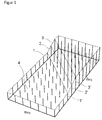
- the present invention relates to a method for dressing a tool, which can be used for gear processing of a workpiece, on a dressing machine, wherein the dressing takes place with line contact between dresser and tool.
- the present invention relates to a method for dressing a grinding worm, which can be used for gear processing of a workpiece, and / or a method for dressing a tool, which can be used for a Wälzvertechnikbearbeitung a workpiece.
- the tool can be used for generating grinding of a toothed workpiece, in particular for generating grinding of a toothed wheel.
- dresser with a circular or elliptical profile used, the profile can be made very flexible. Due to the small contact surface, however, many strokes are necessary and the profile has a high roughness. If dressers with a short straight profile shape are used, the number of strokes can be reduced. However, profile modifications can only be roughly approximated, which results in form deviations.
- the present invention therefore deals with methods of dressing which operate according to the first variant, i. H. in which there is line contact between the dresser and the tool during dressing, resulting in short dressing times.
- Direction which is perpendicular to the first direction, given by a function f (x).
- f (x) a function for adjusting a worm to be spherical over its width by changing the axial distance during dressing.
- DE19624842A1 and the DE 19706867 Methods are known in which by a constant change in the position of the dresser to the tool during dressing a screw is generated whose profile angle varies over its width.
- the object of the present invention is to further develop a method for dressing a tool, in which line contact is made between the dresser and the tool, in such a way that the flexibility with regard to the producible modifications of the surface geometry of the tool is increased.
- the present invention shows, in a first aspect, a method for dressing a tool, which can be used for tooth processing of a workpiece, on a dressing machine, wherein the dressing takes place with line contact between the dresser and the tool.
- a targeted modification of the surface geometry of the tool is generated by the appropriate choice of the position of the dresser to the tool during dressing.
- the inventive method according to the first aspect offers a plurality of variants, as this specific modification of the surface geometry of the tool can be predetermined, which are described in more detail below. All variants are based on the recognition underlying the present invention that modifications of the surface geometry of the tool can be achieved by the targeted adjustment of further degrees of freedom of the position between dresser and tool, which go beyond the known from the prior art modification of the profile angle.
- the targeted modification of the surface geometry of the tool can be specified on at least three angles of rotation.
- a crowning of the targeted modification of the surface geometry of the tool can be predetermined.
- the present invention is not limited to the modification of a profile angle or the specification of the modification of two rolling angles, but also allows a modification of the crown or a default on three angles of rolling.
- the targeted modification of the surface geometry of the tool on at least two rolling angles and / or a slope of the targeted modification of the surface geometry of the tool can be predetermined, and additionally an assignment of a certain radius of the dresser to a certain radius of the tool.
- the assignment of a certain radius of the dresser to a certain radius of the tool has on the one hand production engineering advantages, for example by an undercut of the toothing is prevented.
- the assignment of the radii can also be used for the targeted placement of a modification present in the dresser on the tool.
- an assignment of two specific radii of the dresser can be made to two specific radii of the tool. Even such an assignment of two radii of the dresser to two radii of the tool can bring to a manufacturing advantages. On the other hand, such an assignment allows for increased control over the resulting modifications, and may, for example, when using a modified dresser, place the modifications at corresponding positions of the tool or create a compression or extension of the modification on the tool.
- the predeterminable according to these three variants geometry or assignment is then generated according to the invention by a corresponding control of the axes of movement of the dressing machine when dressing the tool.
- the three variants just described can also be combined with each other.
- a fourth variant of the present invention according to the first aspect which is preferably combined with at least one of the first three variants, during dressing the tool rotation angle and the tool width position are changed in order to guide the dresser along the tool and at least two further degrees of freedom of the relative Position between dresser and tool independently of each other for influencing the Verniergeometrie generated by dressing and / or assigned to assign a certain radius of the dresser to a certain radius of the tool.
- more degrees of freedom of the relative position between the dresser and the tool are set independently of one another than was the case in accordance with the prior art in order to make possible the additional modifications and / or assignments possible according to the invention.
- At least three further degrees of freedom are preferably set independently of one another in addition to the coupling between the tool rotation angle and the tool width position.
- the adjustment of the axes of movement according to the fourth variant of the present invention can be used to produce the modifications and / or assignments in the dressing according to one of the first three variants.
- the present invention is based on the finding that additional modifications and / or assignments are possible by using at least one further degree of freedom.
- at least four degrees of freedom may be used instead of the three degrees of freedom used according to the prior art.
- all of the available five degrees of freedom are used, resulting in additional possibilities for specifying the modification and / or the assignment.
- the desired modification of the tool to four rolling angles can be specified. This results in an even greater freedom in the specification of the desired modification.
- the first variant can be further developed to the effect that in addition to the specification of the desired modification of the tool to three rolling angles an assignment of a certain radius of the dresser to a certain radius of the tool. It is thus a combination of the above-mentioned first and second variants, wherein the assignment of the specific radius of the dresser to a certain radius of the tool can in turn bring manufacturing advantages, and / or can be used to place a modification of the dresser.
- the second variant described above can be combined with the third variant described above.
- a specification of the targeted modification of the surface geometry of the tool to at least two rolling angles and / or a specification of a slope of the targeted modification of the surface geometry of the tool.
- the specification of the targeted modification of the surface geometry of the tool can be done by specifying a desired modification of the surface geometry of a workpiece to be machined with the tool.
- a desired modification of the surface geometry of a workpiece to be machined can first be predetermined, and from this desired modification of the surface geometry of the tool to be machined Workpiece the necessary modification of the surface geometry of the tool can be determined. Preference is given to the specifications of the surface geometry, which were described above with respect to the surface geometry of the tool, replaced by corresponding specifications of the surface geometry of the workpiece or are defined by this.
- the targeted modification of the surface geometry of the tool or desired modification of the surface geometry of the workpiece may be a pure profile modification.
- the remaining degrees of freedom are not changed during the dressing process, but are fixed to generate the desired profile modification and / or assignment of the radii.
- a modified dresser is used and results in the generated profile modification of the tool from the profile modification of the dresser and the set axes of movement of the dressing machine.
- the modification of the surface geometry of the tool is combined by a corresponding adjustment of the relative position between dresser and tool during dressing with a profile modification, which results from the modification of the shape of the dresser.
- the present invention thus considerably expands the possibilities of using modified dresser.
- a modified dresser can be adapted to the diameter of the tool that changes as a result of repeated dressing.
- a compensation calculation can be used to determine a relative position between dresser and tool during dressing, by which the desired profile modification is at least approximately generated.
- the proportion of the profile modification of the tool generated by the setting of the axes of movement of the dressing machine is predetermined or determined on at least one, and preferably two or three, angles of roll. Furthermore, it can be provided that a desired position of the profile modification of the dresser is predetermined or determined on the tool.
- a desired stretching or compression of the profile modification of the dresser can be predetermined or determined on the tool.
- the profile modification produced by the dresser in the event that the profile modification produced by the modified dresser does not correspond to the desired modification, the profile modification produced by the dresser can be stretched or compressed. In particular, this can be done by an inventive assignment of two radii of the dresser to two radii of the tool.
- a suitable profile angle of the tool can be selected. This is based on the knowledge that the same toothing can be ground with different profile angles of the tool. Therefore, the profile angle of the tool can also be adjusted so as to have a further degree of freedom in the specification or generation of a modification available. In particular, by the selection of a suitable profile angle, a stretching or compression of the profile modification of the dresser can be at least partially compensated, if this is not desired.
- the method according to the invention for producing a profile modification according to the second aspect can be configured as already described in more detail above with regard to the first aspect.
- specifications or assignments according to the invention can only be predetermined within certain limits.
- a pure profile modification of the tool can be generated.
- the present invention is not limited to the generation of pure profile modifications, but may also produce modifications that vary over the tool width.
- the targeted modification of the surface geometry of the tool or the desired modification of the surface geometry of the workpiece at at least one rolling angle can be predetermined as a function of the tool width position. Preference may be given to the targeted modification of the surface geometry of the tool or the desired modification of the surface geometry of the workpiece be predeterminable at two or three angles as a function of the tool width position.
- the present invention thus allows a variety of topological modifications.
- the adjustment of the axes of movement of the dressing machine in dependence on the tool width position can be done to produce the targeted modification.
- the relative position between dresser and tool during dressing can be chosen differently according to the invention for different tool width positions, to thereby produce different targeted modifications in the profile direction as a function of the tool width position.
- the assignment of a specific radius of the dresser to a specific radius of the tool can be predetermined as a function of the tool width position. This is particularly advantageous when a modified dresser is used.
- the assignment of a certain radius as a function of the tool width position thus allows the modification of the dresser in the tool width direction at different positions. If the modification of the dresser has, for example, an edge, the course of this edge over the tooth flank can be adjusted according to the invention.
- the adjustment of the axes of movement of the dressing machine can thus take place as a function of the tool width position in order to produce the desired assignment.
- At least one of the rolling angles, at which the modification can be predetermined can be selected differently in the tool width direction.
- this rolling angle can be specified as a function of the tool width position.
- two, three or four rolling angles, at which the modification can be predetermined can be chosen differently in the tool width direction and, in particular, can be predetermined as a function of the tool width position.
- the present invention can be used both in single-flute and in double-flute dressing.
- flanking dressing naturally gives rise to additional possibilities of influencing the modifications which do not exist in double-sided dressing due to the existing dependencies between the left and right flank modifications.
- the dressing can be done einflankig in a possible variant of the dressing and the at least three or four predetermined rolling angle can be arranged on a flank.
- dressing can take place in two layers and the at least three or four rolling angles can be distributed over the two flanks.
- the dressing can be done with two layers and different profile angles can be specified on both flanks.
- a desired crowning the dressing preferably einflankig.
- dressing can take place in two-sided fashion and a tool with a conical basic shape can be used.
- a tool with a conical basic shape can be used.
- the cone angle of the tool can be used to set the desired modification.
- the cone angle provides an additional degree of freedom to influence the modification on the left and right flank differently.
- a modification produced by modification of the dresser can be superimposed with a specific modification of the surface geometry of the tool produced by the adjustment of the position of the dresser to the tool during dressing. For example, in the event that no dresser is available which would produce a desired modification with normal adjustment of the axes of motion, this desired modification can be achieved by overlaying with a modification made by adjusting the dresser's position to the tool.
- the position of the modification produced by a modification of the dresser can be predetermined on the tooth flank.
- the position of the dresser relative to the tool is adjusted so that the modification produced by the dresser modification is placed at a desired position on the tooth flank. This is particularly important if the dresser modification does not run smoothly over the entire tooth height, but has excellent points such as an edge.
- the position of the modification produced by a modification of the dresser can be predetermined on the tooth flank of the tool as a function of the position in the tool width direction. This makes it possible to adjust the position of the modification in the tool width direction vary, and, for example, to produce a tool width directional variation in the position of the edge created by the dresser.
- the position of the modification produced on the tooth flank of the tool by a modification of the dresser can be predetermined or defined by assigning a specific radius of the dresser to a specific radius of the tool.
- the specification or definition of the desired extension or compression of the modification of the dresser is carried out in that two specific radii of the dresser are assigned to two specific radii of the tool.
- a suitable profile angle of the tool can be selected.
- the profile angle can be changed to achieve a desired stretching or compression of the modification.
- the tool can be equipped with a profile angle, which together with the selected position of the dresser relative to the tool results in a desired stretching or compression of the modification of the dresser or prevents unwanted stretching or compression of the modification of the dresser.
- the modified dresser may have a constant modification over its complete active profile.
- a uniform crown over the entire active profile can be provided.
- the modified dresser may have a modification in at least one partial region of its profile which differs from the profile shape in at least one second partial region.
- more than two subregions may be provided with different modifications.
- the modification in the first partial region can have a different profile angle and / or a different crowning than the modification in the second partial region.
- the modification in the first partial area and / or in the transition between the first and the second partial area may have an edge.
- the dresser is preferably in contact with the tool surface at the same time as the first and the second portion. As a result, in each case different modifications during dressing can be produced in only one stroke in both partial areas. If the dresser has more than two subareas, then preferably all subareas are simultaneously in contact with the surface of the tool during dressing.
- the sections of the dresser can preferably cover substantially the entire tooth height of the tool, so that the dressing takes place over the entire tooth height in one stroke.
- a combination dresser for simultaneous dressing of the tooth head and the tooth flank can be used.
- the height of the tooth head can be predetermined and generated by adjusting the axes of movement of the dressing machine during dressing. In particular, this can be done by a corresponding assignment of a radius of the dresser to a radius of the tool.
- the height of the tooth head can be predetermined as a function of the tool width position. As a result, the height of the tooth head can be varied over the width of the tool.
- the dressing machine may have more axes of motion than geometric degrees of freedom in adjusting the relative position between the dresser and the tool. In this case, for a specific desired relative position between dresser and tool a plurality of settings of the axes of movement of the dressing machine, which generate this relative position.
- a setting is selected which better fulfills given conditions.
- a setting can be selected which provides the desired relative position with higher accuracy and / or lower position errors. It can be considered in particular that the accuracy of the axes of motion can be different depending on the specific position of the axes of movement.
- a setting can be selected, which requires lower movements of the machine axes.
- kinematic aspects can also be taken into account during the machining process, in particular if a position of the dresser that varies over the tooth width of the tool is used.
- a setting can be selected which avoids collisions of the dresser, the tool and / or the machine parts with each other.
- the movements of the machine axis which may be necessary in accordance with the invention in order to produce the desired modifications, can be considerably higher than the travel movements of the machine axes which are normally required in the course of a dressing process.
- the settings are therefore preferably chosen so that collisions are nevertheless avoided.
- the tooth geometry produced by the dressing on the tool and / or the tooth geometry generated by the tool on the workpiece can be measured and deviations from a desired geometry the deviations of the axes of movement of the dressing machine from their nominal values during dressing Positions are determined.
- deviations of the axes of motion can be detected and corrected from their desired positions.
- the degrees of freedom available are preferably used to produce the desired modification.
- four or five degrees of freedom are used.
- the degrees of freedom are set independently to produce the desired modification.
- the degrees of freedom which can be set according to the invention can be, in particular, three, four or all of the following five degrees of freedom: angle of rotation of the tool, axial position of the tool, ⁇ -position of the dresser, center distance and / or Axis intersection.
- degrees of freedom are geometrical degrees of freedom which, depending on the design of the dressing machine, can be made available by controlling different axes of movement.
- the axial position of the tool, d. H. the tool width position can be used to move the contact line of the dresser.
- two, three or four degrees of freedom are independently set to produce the targeted modification along the line of contact.
- a dresser designed on a tool having a first macrogeometry and / or a first desired surface geometry may be used to dress a tool having a second macrogeometry and / or second desired surface geometry.
- the present method thus makes it possible to use dresser not only for tools for which the dresser was actually designed, but also for tools with a different macrogeometry.
- a dresser may be used for a tool having a macrogeometry for which it has been designed, but which, by the modifications according to the invention, produce a different surface geometry than that provided in the design of the dresser.
- the errors resulting from the design on the tool with the first macrogeometry and / or the first desired surface geometry when dressing the second tool by a corresponding adjustment of the axes of movement of the dressing machine when dressing the tool with a second macrogeometry and / or second desired surface geometry be at least partially or completely compensated.
- a typical application is the small series production of a variety of different gears with different tooth geometry.
- a specific new dresser no longer has to be created for each application.
- the adjustment of the axes of movement of the dressing machine during dressing and / or the macro geometry of the dresser and / or the modification of the dresser and / or the macrogeometry of the tool can be determined by means of a compensation calculation.
- a suitable adjustment of the axes of movement of the dressing machine during dressing and / or a suitable macrogeometry of the tool can be determined by means of a compensation calculation.
- the settings of the axes of movement of the dressing machine are always determined during dressing as part of the compensation calculation.
- the modifications in the rolling pattern achievable by changing the setting of the axes of movement of the dressing machine can be varied in one direction with an angle ⁇ FS to the tool width direction at two, three or four rolling angles and interpolated along their direction and preferably as linear, square and / or cubic functions.
- ⁇ FS angle to the tool width direction
- such an achievable modification is then compared with a desired modification.
- a distance function can be used to quantify the deviation.
- the distance function can have a weighting that is dependent on the position in the rolling image. In particular, this can be taken into account be that the tolerances for different positions in the Wälzsent can be different sizes.
- a tool may be used in which at least one gear is inactive and / or recessed.
- the changes in the position of the dresser relative to the tool according to the present invention must in some cases be relatively large in order to produce the desired modifications. In this case, it may happen that the dresser engages during the dressing of a first edge at least partially in the contour of the opposite edge. If at least one gear is inactive and / or recessed, this provides more space for the dresser during dressing.
- a tooth flank can be dressed in such a way that it does not come into contact with the workpiece during machining of the workpiece and is therefore inactive. This makes it irrelevant if this gear unintentionally gets in contact with the dresser when dressing the opposite edge and therefore receives an undesirable contour.
- at least one gear is trained so that it does not come into contact with the workpiece during machining of the workpiece and therefore is inactive.
- At least one inactive and / or recessed passage is provided between two active gears.
- more dressing space is available for dressing the flanks of the active gears, since at least one inactive and / or recessed gear is provided between the two active gears.
- the workpiece depending on the number of teeth of the workpiece and / or the number of gears of the tool in at least a first passage at least a first part of the teeth of the workpiece are processed, after which the workpiece is rotated relative to the tool to at least a second To process part of the teeth in at least a second pass.
- This will ensure that All teeth of the workpiece are actually processed.
- more than two passes can be used to machine the teeth of the workpiece.
- the dressing can take place with a line contact extending over the entire tooth height of the workpiece to the dresser, and thus the entire tooth height can be dressed in one stroke.
- the dressing can take place in two or more strokes each with line contact. Unlike in line editing, however, line contact and thus relatively few strokes are still used here. Over the tooth height, however, several strokes are used to achieve even greater flexibility with regard to the modification of the tool surface.
- the axes of movement of the dressing machine during dressing in the respective stroke are set differently in addition to the required for the different positioning between dresser and tool in the two or more strokes change in position.
- the pitch and / or crown of the modification in at least one of the strokes can be influenced by a corresponding change in the relative position between the dresser and the tool.
- slope of the modification As far as is spoken in the context of the present application of a slope of the modification, it is in accordance with the usual choice of words in the context of the gear technology actually to the profile angle or the profile angle error. However, the term slope is chosen to make the geometric relationships clearer, since the profile angle is the slope of the tooth flank in the height direction.
- the targeted modification in at least one of the strokes can be adjusted such that the surface geometry generated by the at least one first stroke follows at a desired angle and in particular tangentially to the surface geometry generated by at least one second stroke. This guarantees a tangential transition between the areas trained by the individual strokes. According to the invention, the roughness of the machined surface present during line dressing is therefore also avoided within the scope of the present invention.
- the modifications for all strokes can be adjusted so that the surface geometries generated by the individual strokes in one connect desired angle and in particular tangentially to the surface geometries generated by the adjacent strokes.
- a desired modification of the tool to at least two and preferably three rolling angles is preferably predetermined for at least one and further preferably each stroke. Furthermore, for at least one and preferably each stroke, an assignment of a specific radius of the dresser to a specific radius of the tool is preferably carried out. By assigning the radii, the areas are defined, which are covered by the respective strokes.
- different areas of the dresser can be used for the individual strokes.
- different dressers can also be used for the individual strokes. This makes it possible, in addition, to produce additional modifications by differently modified regions of the dresser or differently modified dresser by the different modification produced by the adjustment of the machine axes.
- one of the strokes may be used to produce a modification of the tooth root or the tooth head, for example for generating a return of the tooth head or tooth root.
- a second stroke can then be used for example for dressing the tooth flank.
- the position or the positions at which the modifications produced in the respective strokes adjoin one another can also be changed as a function of the tool width position. This results in an additional flexibility in the variation of the modification in the tool width direction.
- At least one of the strokes used is carried out according to a method according to the invention.
- all strokes are preferably carried out according to a method according to the invention.
- the individual strokes can be used to produce a pure profile modification.
- one or several strokes are used to produce a topological modification, ie vary the modification in the tool width direction.
- the present invention further comprises a method for producing a workpiece with modified tooth geometry by a rolling method by means of a modified tool, wherein a targeted modification of the surface geometry of the tool is generated by a dressing method according to the invention and the targeted modification of the tool generated by the rolling process a corresponding modification on the surface of the workpiece.
- a diagonal rolling process can be used for machining the workpiece. By such a diagonal rolling process, it is possible to image a topological modification of the surface geometry of the tool on the workpiece.
- a modification of the surface geometry of the tool varying in the width direction according to the dressing method according to the invention can be used to produce a corresponding variation of the modification of the workpiece in the workpiece width direction by a diagonal rolling method.
- the diagonal rolling process forms the variation of the tool on the surface of the workpiece.
- the present invention can also be used to produce a pure profile modification of the workpiece.
- an axial rolling method is preferably used for producing the workpiece.
- a desired modification of the surface geometry of a workpiece to be machined with the tool can be determined and from this the specific modification of the surface geometry of the tool required for its production can be determined. Preference is given to the specifications of the surface geometry, which were described above with respect to the surface geometry of the tool, replaced by corresponding specifications of the surface geometry of the workpiece or are defined by this.
- the present invention further comprises a device and / or a software program for calculating the relative position between the dresser and the tool necessary for producing a desired modification of a tool during dressing in line contact with a given dresser or the settings of the axes of movement of a tool necessary for its provision Abrichtmaschine.
- the present invention protects both the device and the software program as such and independently of one another.
- the software program can be processed on the device according to the invention.
- the software program can also be stored, for example, on a data medium or in a memory.
- the device may in particular be a computer and / or a machine control. On this or this may preferably run according to the invention a software program.
- the inventive device or software program according to the invention in this case comprises an input function by which the targeted modification of the surface geometry of the tool is specifiable and a calculation function, which from the targeted modification necessary for their production during dressing with line contact between dresser and tool relative position between dresser and Tool or the necessary to provide their settings of the axes of movement of the dressing determined.
- the input function and the calculation function can be designed such that they can be used to carry out one of the methods of the invention described above in greater detail.
- the device or the software program may altogether serve to carry out a method according to the invention or may be used in the context of such a method.
- the input function and the calculation function can be designed such that the specific modification of the surface geometry of the tool can be predetermined to at least three rolling angles and can be generated there by the calculated relative position or setting of the axes of movement of the dressing machine.
- the input function and the calculation function can be designed such that a crowning of the toothing can be predetermined and can be generated by the calculated relative position or setting of the axes of movement of the dressing machine.
- the input function and the calculation function can be designed such that the specific modification of the surface geometry of the tool can be predetermined at at least two rolling angles and generated there by the calculated relative position or setting of the axes of movement of the dressing machines and additionally an assignment of a certain radius of the dresser is predeterminable or calculable to a certain radius of the tool and takes place by the calculated relative position or setting of the axes of movement of the dressing machine.
- the input function and the calculation function can be designed such that a slope of the modification of the toothing can be predetermined and generated by the calculated relative position or setting of the axes of movement of the dressing machine and additionally an assignment of a specific radius of the dresser to a specific radius of the tool can be predefined or calculated and is carried out by the calculated relative position or setting of the axes of movement of the dressing machine.
- the input function and the calculation function can be designed so that an assignment of two specific radii of the dresser to two specific radii of the tool.
- the input function and the calculation function can be designed so that data can be entered to a modified dresser and the determination unit determines the setting of the axes of movement of the dressing so that a desired profile modification of the tool at least approximately and preferably exactly from the profile modification of Dresser and the set axes of movement of the dressing machine results.
- the input function and the calculation function are designed so that several of the above-mentioned variants are realized. Preferably, therefore, the user can select from several of these provided by the input function and the calculation function variants.
- the input function and the calculation function preferably provide at least two, more preferably at least three, or at least four of the abovementioned variants.
- the input function according to the invention and the calculation function are each designed such that they can be used to carry out a method according to the invention.
- the specification or the calculation takes place in the same way as has already been described above in more detail with regard to the methods according to the invention.
- the input function can be designed so that a desired modification of the surface geometry of the workpiece, which is to be processed with the tool, can be predetermined, the input function generates the above-mentioned data for the purposeful modification of the surface geometry of the tool.
- the controller has in each case an input function by which the targeted modification of the surface geometry of the tool can be specified, and a calculation function, which from the targeted modification necessary for their production settings of the axes of motion during dressing with line contact between dresser and tool determines. Furthermore, the controller has a control function, which makes a corresponding adjustment of the axes of motion during dressing with line contact between dresser and tool.
- the input function, the calculation function and the control function can each be designed such that they can be used to carry out one of the aforementioned methods.
- the input function, the calculation function and the control function can be designed so that the specific modification of the surface geometry of the tool can be predetermined to at least three rolling angles and generated there by adjusting the axes of movement of the dressing machine.
- the configuration can be made such that a crown of the toothing can be predetermined and generated by adjusting the axes of movement of the dressing machine.
- the input function, the calculation function and the control function can be designed so that the specific modification of the surface geometry of the tool at at least two rolling angles predetermined and there by adjusting the axes of movement of the dressing machine is generated and additionally an assignment of a certain radius of the dresser is predetermined or calculated to a certain radius of the tool and is done by adjusting the axes of movement of the dressing machine.
- the input function, the calculation function and the control function can be designed such that a slope of the modification of the toothing can be predetermined and generated by adjusting the axes of movement of the dressing machine and additionally predetermining an assignment of a specific radius of the dresser to a specific radius of the tool is or is calculated and is done by adjusting the axes of movement of the dressing machine.
- the input function, the calculation function and the control function can be configured so that an assignment of two specific radii of the dresser to two specific radii of the tool.
- the input function, the calculation function and the control function can be designed so that data can be entered to a modified dresser and the determination unit determines the setting of the axes of movement of the dressing so that a desired profile modification of the tool at least approximately from the profile modification of Dresser and the set axes of movement of the dressing machine results.
- the controller may implement several of the described variants, in particular as different modes of operation.
- the dressing machine or gear cutting machine according to the invention may preferably be designed such that they can be used for carrying out a method according to the invention as described above.
- the presetting of the values or the determination of the axes of motion preferably takes place in the manner described above.
- the determination and the control takes place automatically.
- the input function, the calculation function and the control function are configured such that several of the variants described with regard to the methods according to the invention are available and one of these variants can be selected by the user.
- the dressing machine or gear cutting machine preferably comprises a device for calculating the relative position between dresser and tool necessary for producing a desired modification of a tool during dressing in line contact, as described above, and / or comprises a corresponding software program, as described above ,
- the methods according to the invention are preferably carried out using a device according to the invention and / or a software program according to the invention and / or a dressing machine according to the invention and / or a gear cutting machine according to the invention.
- the dressing machine can be a machine that is used exclusively for dressing tools and has no additional functionality for machining workpieces with such tools.
- the dressing machine is a combination machine, which allows both a machining of workpieces, as well as the dressing.
- it may be a gear cutting machine with a dressing machine according to the invention, wherein the gear cutting machine in addition to the dressing machine comprises a processing machine, via which a gear processing with the inventively dressed tool is possible.
- the processing machine and the dressing machine can share single or multiple shots or axes of motion.
- the gear processing according to the invention is preferably a hob machining method, in particular a hobbing method. Particularly preferred is a Diagonal maybelzmaschinen used.
- the tool which is dressed or used according to the invention, is preferably a grinding worm.
- a dresser according to the invention preferably a profile or form roller is used.
- the method according to the invention and the devices or tools according to the invention are preferably designed such that, according to the invention, an involute toothing is produced on the workpiece.
- the relative position of the dresser to the tool during dressing with line contact can be selectively adjusted so that the contact line between dresser and tool shifts on the dresser to thereby influence the active along the contact line, transmitted to the tool profile.
- this will produce the desired modification on the tool.
- the pitch and / or crown can be adjusted or changed along the contact line on the tool.
- This contact line on the tool preferably defines the first direction of the modification on the tool.
- the inclination in a first direction of the tool which includes an angle ⁇ FS or ⁇ F1 not equal to the tool width direction, and in particular a proportion in the profile direction, ie the slope of the modification, is referred to as the slope of the targeted modification in the sense of the present invention corresponds to the profile angle or a profile angle deviation.
- a crowning in a first direction which includes an angle ⁇ FS or ⁇ F1 not equal to zero to the tool width direction, and in particular has a portion in the profile direction, ie the crown of the modification corresponds to one Profilballmaschine.
- the first part of the invention relates to a method of dressing tools for gear cutting, and will be described in more detail below with reference to scrolling screws.
- the screws may be symmetrical or asymmetric and may be cylindrical or conical. You can have all the profiles that are suitable for Wälzschleifen rolling gears, in particular, the screws may have involute profiles.
- coordinates are used here for generalized, not necessarily independent coordinates.
- the axis of rotation of the screw or the dresser always coincides with the z-axis in the respective rest systems.
- the calculation of the coordinates B 1 ,..., B NS can be carried out by means of a coordinate transformation.
- H R z - ⁇ B 1 ⁇ T z - ⁇ V 1 ⁇ R x - ⁇ A 1 ⁇ T x - ⁇ X 1 ⁇ T y ⁇ Z 1 ⁇ R y ⁇ C 5 ⁇ R z ⁇ B 3
- Example 2 R z - ⁇ B 1 ⁇ T z - ⁇ V 1 ⁇ R x - ⁇ A 1 ⁇ T x - ⁇ X 1 ⁇ T y ⁇ Z 1 ⁇ R z ⁇ B 3
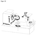
- FIG. 22 A gear cutting machine having a musculoskeletal system as in these two examples is shown in FIG. 22 shown.
- the subscript B1, V1, A1, X1, Z1, C5, B3 in formulas (4) and (5) refers in each case to the machine axes shown there.
- FIG. 22 shows a perspective view of a gear cutting machine with a dressing machine, which is used for carrying out the method according to the invention.
- the gear cutting machine has a machining head shown on the left with a tool holder, a workpiece holder shown centrally and a dresser holder shown schematically on the right.
- a workpiece clamped in the workpiece holder can be machined by a tool clamped in the tool holder.
- the tool clamped in the tool holder can be machined by a dresser clamped in the dresser holder. This has the advantage that the tool for dressing can remain in the tool holder.
- the axes of movement of the machining head for adjusting the relative position of the tool and dresser can be used in the dresser.
- the gear cutting machine has the axes of movement A1, B1, V1, X1, Z1 for moving the tool holder, C2 for moving the workpiece holder, and B3, C5 for moving the dresser.
- B1 allows a rotation of the tool about its axis of rotation
- X1 a translational movement of the tool perpendicular to the axis of rotation of the tool or workpiece
- Z1 a translational movement of the tool in the vertical direction or parallel to the axis of rotation of the workpiece
- A1 a pivotal movement of the tool
- V1 a tangential movement or shift movement of the tool in the direction of its axis of rotation
- C2 a rotational movement of the workpiece
- B3 a rotational movement of the dressing tool about its axis of rotation
- C5 a pivoting movement of the dressing tool to change the pressure angle ⁇ on the tool.
- the idea of the invention is to consider, during the dressing process, the 5 degrees of freedom ⁇ S , ⁇ zs , y, d and ⁇ y A from equation (28) in order to influence the profile shape of the screw. Due to the rotational symmetry of the dresser, the degree of freedom ⁇ A plays no role in the consideration made here.
- W FS is the rolling path (also referred to as rolling length); for non-involute profiles, it is a parameter for parameterizing the profile. In the following, however, the term "rolling path" is also used for non-involute gears.
- a toothing with a profile modification ie a modification that depends only on the rolling path w FV and not on b FV , is roll-ground
- a corresponding profile modification must be introduced into the worm.
- a radius on the worm r S is assigned to each radius within the area to be ground on the toothing r V. This assignment must be carried out in principle for each screw diameter.
- each radius on the screw r S must be assigned a radius on the dresser r A and a corresponding modification introduced on the dresser at these assigned radii become.
- the dresser can be used over a wide range of screw diameters, depending on the dresser and screw geometry, and the screws produced in this way produce the correct profile modification on the ground toothing. If, however, the above-mentioned dressing kinematics are used during dressing in order to freely specify the modification on the screw at 4 points within certain limits, this generally means that the correct assignment between radii on the screw and radii on the dresser can no longer be guaranteed , If this occurs, this leads to a shift of the profile modification on the screw to a smaller or larger radius. This incorrect placement of the profile modification on the screw then leads to a wrong placement of the profile modification on the toothing.
- the dressing kinematics can be chosen so that the dresser touches the screw at a given radius at a given radius. If, in the example just given, the tip retraction at the dresser is selected as the radius at which the bend is placed and at the worm the radius which makes the radius on the toothing on which the bend is to be placed, this problem can be avoided , However, this means that you can specify the profile modification on the profile only at 3 instead of 4 digits. However, this default at only 3 digits is sufficient, for example, to apply profile crowns on an involute screw, which in turn lead to profile crowns on a ground involute toothing.
- inputs to such dresser simulations usually also include the geometry of the screw before dressing.
- the auger prior to dressing is chosen in the following consideration to have a positive allowance to the auger after dressing throughout the aisle.
- the dressing process is typically subdivided into a finite number of time steps and then determined for each time where material is removed from the screw by the dresser.
- a, usually unmodified screw is considered first.
- On individual points with the coordinates (w FS , b FS ) on the flights of this screw vectors are placed in the normal direction with a predetermined length.
- the length of the vectors corresponds to the oversize of the screw before dressing, relative to the unmodified screw.
- the allowance is typically chosen so large that each vector is truncated at least once during the simulation described below.
- the number of points on the aisles determines the accuracy of the result. Preferably, these points are chosen equidistantly.
- the relative position of the screw to dresser is given at any time, for example, by the coordinates of the uncorrected kinematics ⁇ S , ⁇ , d, ⁇ yA and their corrections ⁇ K.
- the intersection of all vectors is calculated with the dresser. If a vector does not cut the dresser, it will remain unchanged. However, if he cuts the dresser, the intersection is calculated and the vector is shortened so far that it ends just at the intersection. Furthermore, the distance of the point of intersection from the dresser axis, that is, the radius on the dresser r A of the point of intersection is calculated and stored as additional information to the just shortened vector.
- the small differences in lengths are due to the fact that the algorithm described here causes feed marks due to the discretization of time. These feed marks and thus also the differences in the lengths of the vectors on a given radius of the screw can be reduced by a finer discretization of time, equivalent to a shortening of the time steps. If the simulation is not carried out over the entire width of the screw, but is interrupted at a given axial shift position ⁇ zS of the screw, then for a given radius on the screw only the vectors have approximately the same length as the contact line of the dresser with the screw already been crossed out. The remaining vectors either still have the originally chosen length or have already been truncated at least once, but do not yet have the final length since they will be truncated at a later time.
- This fact can be used to determine very precisely the contact line for the given dresser and the given relative position of the screw to the dresser, described by ⁇ K .
- all vectors are considered for a given radius on the worm r FS or Wälzweg w FS and determines at which latitudinal line position the transition from vectors of approximately equal length to those with a different length.
- the touch line can thus be described by a function b BRFS or b BwFS , depending on the corrections ⁇ K and ⁇ z S.
- b FS b BRFS r FS v z S .DELTA.K respectively
- b FS b bwfs w FS v z S .DELTA.K
- ⁇ FS ( ⁇ K) describes the direction
- X FS ( ⁇ zS , ⁇ K) describes the position of the line.
- the dependence of the direction ⁇ FS ( ⁇ K) on the corrections ⁇ K is only slight, so that, in still a good approximation, the direction can be assumed to be given only by the screws and dresser geometry .
- the radii stored for these previously stored on the dresser r FA can thus be determined for each radius on the screw r FS , from which radius on the dresser r FA it was dressed , This assignment depends on the corrections ⁇ K.
- r FA r FA r FS ; .DELTA.K
- the accuracy with which the touch line and the assignment of the radii can be determined in this way depends both on the selected distance of the points and on the length of the discrete time steps. Both can theoretically be chosen arbitrarily small, but in practice they are limited by the available main memory and the maximum acceptable computing time. With the PCs available today with several gigabytes of RAM and very fast multi-core processors, this calculation is possible in practice with sufficient accuracy.
- F 4 F F 4 .DELTA.K f nFS w F 1 .DELTA.K - f FS 1 f nFS w F 2 .DELTA.K - f FS 2 f nFS w F 3 .DELTA.K - f FS 3 f nFS w F 4 .DELTA.K - f FS 4 to construct.
- the zeros of F FS4 can be calculated which correspond to the corrections ⁇ K that have to be set in order to achieve the desired profile modification on the worm at the rolling angles (w FS1 , w FS2, FS3 w to generate w FS4). If the function F FS4 has no zero, the profile modification can not be generated exactly.
- the profile modification is considered on only 4 pitch paths.
- the profile modification along the whole profile, ie for all rolling paths, can be determined with f nFS (w FS , ⁇ K) from the calculated corrections ⁇ K.
- the zero-point calculation can be carried out using the methods known from numerical mathematics, for example the multi-dimensional Newton method.
- the necessary partial derivatives of F FS 4 can be calculated numerically. For this purpose, it is necessary to be able to calculate the function F FS 4 and thus also the function f nFS (w FS , ⁇ K) with high accuracy, which, as described above, is possible with the algorithm presented here. Likewise, it can be checked with such a numerical method whether F FS 4 has any zero at all. For example, in Newton's method, this is reflected in the convergence that is taking place. These considerations for the numerical calculation of zeros also apply to the other variants presented.
- equation (8) makes it possible to specify the position of the touch line at a time such that a point (w FS0 , b FS0 ) given on the worm lies on the line of contact.
- b FS 0 b bwfs w FS 0 v z S .DELTA.K which together with the function F FS 4 from equation (12) for the definition of the function F F4 F ⁇ F 4 ⁇ K .
- v z S f nFS w FS 1 .DELTA.K - f FS 1 f nFS w FS 2 .DELTA.K - f FS 2 f nFS w FS 3 .DELTA.K - f FS 3 f nFS w FS 4 .DELTA.K - f FS 4 b bwfs w FS 0 v z S .DELTA.K - b FS 0 can be used.
- the zeros of this function also provide an axial position of the screw ⁇ zS , so that the desired modification is produced and the line of contact passes through the points (w FS 0 , b FS 0 ). This makes it possible to target only certain areas on the screw and it makes it possible to keep the necessary during dressing overflow as low as possible.
- modifications f FSi receive a dependence on the position in the width direction b FS .
- This extension is of particular interest when the dressed screw is to be used for generating grinding in the diagonal rolling process.
- the likewise topological modification f nFS (w FS , b FS ) on the screw in this case has a dependence on w FS and b FS .
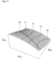
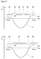
- the w FSi (b FS ) define on which rolling paths, depending on the position in the width line direction, at which points on the worm the target modification during dressing is to be reached exactly (see FIG. 2 ).
- the 4-point method has the disadvantage that it does not allow control over the placement of the screw-in modification introduced into the dresser.
- 3-point method only 3 modifications f FSi are considered at 3 initially restored rolling angles w FSi .
- the radius r FA on the dresser is to produce the radius r FS on the worm.
- This method can also be extended to include the option of specifying a point (w FS0 , b FS0 ) to be on the current touch line.
- the function F F 3 must be extended analogously to equation (14) to the function F F 3 .
- f FS 2 / cos ⁇ bFV is referred to here as c ⁇ FS , since this choice of the modifications F FSi and the rolling angle w FSi leads to a profile crowning between the rolling wins w FS1 and w FS3 with the value f FS 2 / cos ⁇ bFV .
- This special case was chosen here because the profile crowning essentially determines whether the desired modification can be achieved with a given worm and dresser geometry.
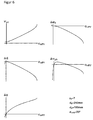
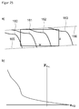
- the course of the axis corrections have over the entire range of achievable on the toothing profile crowning complex forms, which can not be described by simple functions (see FIG. 6 ). In particular, it is not possible to conclude reliably from the progressions in the case of small profile crowns in the entire course. It is thus always advisable to carry out the calculation for the desired profile crowning.
- the axis corrections ⁇ K and the axial position of the screw ⁇ zS show steep inclines . At the left edge, this steep rise is particularly evident at ⁇ d, ⁇ S and ⁇ yA . These edges mark the maximum and minimum producible profile crowning. Beyond the left and right edges, the function F F 3 no longer has zeros.
- the gradients are strongly influenced by the geometric parameters of the screw and the dresser used. So shows FIG. 8 in that, as the diameter of the screw d S , the corrections ⁇ K and the axial position ⁇ zS increases, in particular ⁇ S , ⁇ d and ⁇ become significantly greater.
- FIG. 9 shows that with decreasing number of flights of the screw z S , the corrections ⁇ K and the axial position ⁇ zS larger, in particular ⁇ S , ⁇ d and ⁇ are significantly larger.
- FIG. 10 shows that with increasing diameter of the dresser d A , the corrections ⁇ K become larger.
- FIG. 11 shows that the corrections ⁇ K and the axial position ⁇ zS become larger with decreasing normal profile angle ⁇ of the screw nFS.
- each point on the root circle on the toothing is typically made from a point on the helical gear of the screw and vice versa
- the correct profile modification is produced on the toothing on the foot molding circle in the example considered here, but an incorrect profile modification is assigned to the head wear circle.
- the profile crowning on the toothing is calculated according to equation (19).
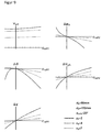
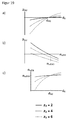
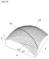
- FIG. 13 shows, using the example of the 3-point method, how the relative profile extension produced during generating grinding on the toothing depends on the profile crowning c ⁇ FV produced on the toothing.
- the four figures show the influence of the number of flights of the screw z S , the diameter of the screw d S , the diameter of the dresser d A and the profile angle of the screw ⁇ nF ⁇ on the dependence of the relative profile extension P FS of the profile crowning on the toothing c ⁇ FV
- the relative profile stretch effect affects the active area available on the dresser.
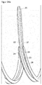
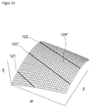
- FIGS. 14a . 14b and 15 show in 3D views from different perspectives and distances the relative position for an uncorrected dressing kinematics, using the example of an involute screw.
- a one-flank dressing is possible without any problems.
- the root 23 of the flight is dressed as desired by the outer surface 20 of the dresser. However, the situation is different when dressing with the 3-point method.
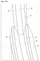
- the FIGS. 16a shows in 3D views from different perspectives and distances the relative position for an uncorrected dressing kinematics, using the example of an involute screw.
- the root 23 of the flight is dressed as desired by the outer surface 20 of the dresser.
- the situation is different when dressing with the 3-point method.
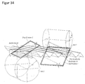
- the FIGS. 16a shows in 3D views from different perspectives and distances the relative position for an uncorrected dressing kinematics, using the example of an involute screw.
- 16b and 17 show for the same screw and the same dresser in 3D views from different perspectives and distances the relative position for a dressing kinematics according to the 3-point method. It shows that the right flank 21 'of the dresser and the outer circumferential surface 20' penetrate the right flank 25 'of the one screw flight. If there is such a penetration, the method can not be used because it leads to an unwanted removal on the right flank 25 '. To avoid this, the dresser can be made narrower. As a result, the outer lateral surface 20 'narrows and the right flank 21' moves closer to the left flank 22 '. The narrowing can theoretically be carried out until the outer lateral surface 20 'has width 0. In practice, however, a minimum width can not be undershot due to production.
- the 3-point method can be extended to the effect that the modification over the worm width is not the same.
- the procedure is analogous and the equations (15), (16) and (17) then apply to 3 points.
- the assignment of the radii on the dresser to the radii on the screw across the width of the screw can be made variable.
- the fourth component of F F3 in equation (18) is through r FA r FS b FS ; .DELTA.K - r FA b FS to be replaced.
- r FA ( b FS ) and r FS ( b FS ) describe the assignment of radii on the dresser to radii on the worm, depending on the worm width position.
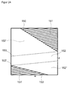
- FIG. 3 shows the modification of a screw which has been dressed with variable allocation of the radii.
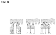
- a dresser for example for involute screws, can not only be used to trim the flanks of a screw, but also to trim the head of the screw at the same time.
- the dressing time can be shortened, because the additional dressing is omitted on a tile, but it is also possible to give the worm head a certain shape to edit the Wälzschleifen the foot of the teeth with.
- Such dressing of the head may be performed on the same flight and at approximately the same width position, but it may be performed on another gear at a different width position (see FIG. 21 ).
- a dresser designed to simultaneously dress the head and flank is usually designed to level the head of the screw at the correct height for a particular dressing kinematics.
- the number of rolling angles at which the modifications are to be achieved must be reduced so that the sum of the number of rolling angles and additional conditions always equals 4.
- the number of rolling angles is at least 2.
- a profile modification placed in the dresser can be additively superimposed.
- the method described in this invention can be applied to double-sided dressing.
- the 3 or 4 rolling angles can be distributed arbitrarily on the two flanks from the 3- or 4-point method.
- the assignment of the radii on the dresser to radii on the check in the 3-point method can be realized on one of the two flanks.
- the modifications that can be produced in double-sided dressing are limited compared to the single-edge production due to the reduced number of considered points per flank, but the double-sided dressing allows shorter dressing times.
- the 4-point variant can be used, for example, to specify allowance and profile angle on both flanks within certain limits.
- the 3-point variant allows only the default 3 of these 4 values, the fourth results automatically, but can be influenced by the geometry of the screw.
- the double-sided dressing can be used both for the production of pure profile modifications as well as topological modifications on the screw.
- the application of this invention does not always have to be over the entire screw width. Thus, only parts of the screw can be dressed with the method underlying the invention. It is also possible to apply several identical or differently modified areas on the screw. Such areas can be used for roughing and / or finishing. It is often the case that two adjacent modified areas can not be placed directly next to each other. This by it The resulting distance between modified areas can optionally be used as a roughing area. This makes it possible to almost completely use a worm subdivided into several partially modified areas.
- the different points considered can optionally be weighted differently, or different distance functions can be used.
- Such a different choice of the distance function or the weighting can be advantageous if the tolerances of the considered points are not all the same. For example, more narrowly tolerated points can be weighted more heavily.
- a typical variant of the compensation calculation, which weights all points equally, is the method of least squares, which uses the 2-norm as a distance function.
- the condition for the assignment of radii on the dresser to radii on the screw can still be maintained in a compensation calculation, so that one obtains an optimization problem with a secondary condition.
- conical screws are meant snails with different pitch heights on the left and right flank. Such a conical screw is in FIG. 36b shown. In the case of involute snails these are called Beveloids.
- radii on the dresser it is of particular importance to assign radii on the dresser to radii on the worm variable over the worm width, since due to the conicity, at each width line position the worm is trued over a different diameter range.
- the points on the worm that grind the beginning of a tip retraction of the gearing are at a different radius at each width position.
- dressers designed for a particular screw diameter can be used for a wide range of screw diameters and produce the desired profile modification on the screw during dressing, which then produces the correct profile modification on the gear.
- this no longer works if the ratio of screw diameter to modulus of the toothing to be ground, too small and / or the number of turns is large. Screws with small diameters are used, for example, when generating grinding with a larger screw is no longer possible due to a disturbing contour. Another application is the grinding of large-modulus gears. Since the usable screw diameters are limited to the top, the ratio of screw diameter to the module decreases with increasing module. With the possibility of modern high-speed machines to realize high table speeds, it is also possible to use screws with larger numbers.
- a dresser designed for the screw in new condition produces an undesirable profile error for smaller radii, in the case of involute screws an undesirable profile crowning, when dressed according to a method according to the prior art. If this profile error or this profile crowning below a screw diameter outside the tolerance, so the screw can not be trained with the given dresser, causing the maximum usable pad thickness is limited. So far this problem can only be solved by using different dressers for different diameter ranges. With the method described here, however, it is possible to keep constant the profile shape over a large diameter range with only one dresser. For this purpose, the dresser is regarded as a dresser which does not fit the screw and the dressing kinematics are determined in such a way that the desired profile shape is produced on the screw.
- the 3-point method is preferably used so that a radius on the dresser can be assigned to a radius on the worm.
- this method results in a generally undesirable relative tread extension on the toothing (see FIG. 19a ).
- Such a relative extension of the profile is not critical if the profile modification introduced in the dresser has to be assigned exactly to a maximum diameter on the toothing. This is the case, for example, if only a return on the profile to be introduced. However, if the profile modification has at least two such diameters, for example a head and a foot return, then these two points would move closer and closer due to the relative profile extension with decreasing screw diameter.
- 19c shows the profile angle determined in this way for different worm radii.
- the combination of the 3-point method with the choice of suitable profile angles makes it possible, with small screw diameters and / or large numbers of gears, to keep the profile shape on the toothing virtually constant over a very large range of the screw diameter.
- the profile error or profile crowning can be corrected analogously. If the relative profile extension is also to be corrected for involute screws, then a correction via the profile angle of the screw during grinding with cylindrical screws is only possible to a limited extent.
- the calculation of the profile angle, which makes the relative tread extension disappear, must be carried out separately on the left and right flank and generally leads to a worm, which no longer is suitable for Wälzschleifen the gearing, since equation (20) is no longer satisfied for both sides.
- it can be used a cylindrical screw whose profile angles are selected on the right and left flank so that the teeth can be ground and the relative profile extension is minimized on the left and right flank.
- the use of a conical (beveloid) screw is possible. The cone angle of this screw can then be selected so that the teeth can be ground with the screw and the relative profile extension is 0 on both flanks.
- dressers which have contact between the screw head and the screw root during dressing.
- the invention makes it possible to influence the profile shape with such dresser, so there are profile modifications that are not possible with a universal dresser. In wage and small batch production, however, high flexibility is required. If dressers with smaller active areas are therefore used, only parts of the profile can be dressed with them per stroke, and in each of these areas the method described here can be used; in particular, the modification can be specified on 3 or 4 pitch paths. This allows a very flexible design of the profile modification, but requires significantly fewer strokes compared to a known from the prior art line leveling with point contact.
- the 3-point method can be used here to assign the active area of the dresser to the area to be dressed in the current stroke in each stroke.
- FIG. 20a shows by way of example a profile modification f nFS , which is composed of the 3 areas 30, 31, 32. In each of these areas, profile angle deviation and profile crowning can be specified separately.
- the areas 30 and 32 are dressed in one stroke, the main profile 31 in 4 strokes.
- the size of the active area on the dresser is chosen here such that the area 34 begins below the foot nr of the paw nfFS . Such a fall below the convennikes is not critical within certain limits, since this area of the screw generally has no contact with the toothing during hobbing.
- a suitably large choice of dresser has the advantage that less strokes are needed for the main profile, compared to an active area, with the Schwarznutz Vietnamese not fell below.
- Such a dresser and a method which describes such a mapping are already from the DE19624842C2 known.
- the dressing in several strokes can not only be used to produce pure profile modifications, but can be transferred directly to the dressing of topologically corrected screws, analogous to dressing in a hub. It is possible to move the areas that are trained during a stroke across the width of the screw. For example, the positions of the transitions between the areas 30 and 31 or 31 and 32 in FIG FIG. 20a be freely specified over the screw width. Such a modified screw can then be used, for example, to realize by means of diagonal roller grinding on the toothing over the tooth width variable start of the head and foot returns.
- a dresser used with several strokes may also already contain modifications that are then placed specifically on the screw.
- a dresser may have an area that is used to create the head return, part of the main profile and the bend between the two, and a second area that is used to create the foot return, part of the main profile, and the bend between the two. If then the upper part of the profile in a stroke with the first area and the lower part trained with the second area, the courses of the beginning of the head orlessness Wegdging across the width of the screw can be specified independently and at the transition between the upper and lower part of the profile, a tangential transition can be realized.
- Such a dressed screw can be used in the diagonal rolling process to freely specify the beginning of head and foot return on the toothing depending on the width position.
- multi-stroke dressing it is also possible in principle to use more than just one dresser, thus allowing individual strokes to be carried out with different dressers. These can have different modifications and / or geometries and thus allow an even more flexible dressing.
- Part of this invention is also a calculation unit / software which, for a given modified toothing for a given set of geometrical sizes, checks the manufacturability with the method according to the invention, preferably taking into account the modification introduced into the dresser. If, for example, a profile crowning of 20 ⁇ m is to be produced in the case of involute toothing, but only one dresser with a modification for producing 15 ⁇ m is available, it must be checked whether, for example, with the 3-point method, a profile crowning of 5 ⁇ m can be generated.
- Such a calculation unit / software may additionally include a function for a set of geometric quantities including dressing modification to a toothing to calculate all modifications that can be generated with the invention.
- the maximum and minimum producible profile crowning can be determined. If the dresser contains a modification which is to be imaged as a profile modification on the toothing and this modification is to be superimposed by a modification produced according to the invention, it is optionally additionally to check whether the modification is still due to the resulting relative extension of the profile Tolerance is correctly mapped on the gearing.
- a computing unit / software may also include functionality to compute modified gearing and an incomplete set of geometric sizes including dresser modification, default values for the remaining geometric sizes. If, for example, the dresser together with the modification and the number of flights of the screw are provided, the diameter of the screw and / or the profile angle of the screw can be determined such that the required modification can be produced by the method according to the invention. If such a calculation unit / software has a database with available dressers and / or screw diameters, the software can determine all combinations suitable for generating a specific modification. Such a database may additionally or instead of the screw diameter also contain data on already pre-profiled available screws. Such data would include, for example, number of flights and / or diameter and / or taper and / or profile angle and / or pitch. Such functionality is of particular interest to pay-dividers, since in this way screws and dresser can be used for different gears.
- Such calculations can be made not only for pure profile modifications, but also for topological modifications on the screw.
- the calculation is carried out, for example, for discrete width positions.
- Such a calculation provides, for example, possible function values for the functions C 0 FS ( X FS ), C 1 FS ( X FS ) and C 2 FS ( X FS ) from equation (23), and thus describes the amount of topological modifications that can be generated, in particular the minimum and maximum producible profile crowning along the Berntonline. If these minimal and maximum required profile crowns are known for a topological modification, then again suitable geometric variables can be determined. Especially for such topological modifications, such functionality is of great importance not only in contract and small batch production, but also in process design for mass production. When reversing the calculation to determine suitable geometric sizes and dressers, the most critical width position is preferably taken into account.
- FIGS. 8 . 9 . 10 and 11 show the sometimes very strong influence four of the geometric variables on the axis corrections.
- over-corrections can be detrimental. If axes are moved too far, for example, collisions between the worm and / or dresser with machine parts can occur.
- Another problem is the increasing by the large travels deviations in the positioning of the dresser relative to the screw.
- the amounts of the axis corrections are orders of magnitude greater than the amounts of the profile modifications to be generated, and in these cases significantly above the axis corrections which are typically required in the prior art methods.
- the influence of such variations on the generated modification, with the function f nFS (w FS; ⁇ K) are calculated, wherein ⁇ K is provided with a deviation. If the deviations of the axes, which are primarily mechanical, are known, depending on the axis corrections, then the influence on the profile modification to be generated and the error in the profile modification can be calculated.
- the geometric sizes can then be determined so that the error in the profile modification is below a given tolerance. This consideration can be transferred directly to the generation of topological modifications, in which case the calculation for different positions of the contact line is preferably to be carried out.
- these different solutions lead to different deviations in the positioning of the dresser relative to the screw and thus to different deviations in the axis corrections ⁇ K.
- the solution is selected which leads to the smallest profile caused by the deviations.
- additional possible collisions between the worm and / or dresser and / or machine parts with other machine parts can be considered when selecting a suitable solution.
- This consideration can be directly transferred to the generation of topological modifications, whereby kinematic aspects can additionally be taken into account when selecting the solution.
- technologically unfavorable direction reversals of one or more axes can be avoided by a suitable choice of the solution in certain cases.
- the unfavorable axis values with large deviations can preferably be set if the contact line passes over areas of great tolerance.
- the deviations of the axes are not known, they can be recalculated from the error caused by them in the profile.
- the calculation on which the invention is based is used in order to calculate the axis corrections ⁇ K from the profile modification actually produced. These are compared with the axis corrections set in the machine during dressing and the difference results in the deviation of the axis values. If a topological modification is dressed, this calculation can be performed for different positions of the touchline. In this way one obtains the deviations for different axis values. If the deviations are known, the axis values can be corrected accordingly for further dressing processes and thus the profile errors minimized.
- the effect of the profile extension can also be used selectively. For example, if a worm is to be dressed with a modified dresser, but the modification introduced into the dresser would produce a stretched or upset profile modification on the worm, then the method of the invention can be used to set the relative tread extension such that the screw produced on the worm Profile modification is properly stretched. If a relative profile extension is produced, for example, involute profiles result in a profile crowning at the same time. How big this is for a given relative stretch depends mainly on the geometrical sizes of the screw and the dresser (see FIG. 13 ). In certain cases, this profile crowning can be so small that substantially only one stretching results, but no superimposition with a profile crowning. To achieve this, the screw geometry can be selected accordingly.
- the screw geometry so that not only the profile extension, but also the profile modification produced by the dressing kinematics, in particular the profile crowning in the case of involute toothing, is achieved according to a specification.
- This can also be transferred to the dressing of topologically modified screws, which makes it possible, with a suitable worm and dressing geometry, specifically to vary the profile extension over the worm width and at the same time only to produce a negligibly small profile crowning.
- the linear coupling in the first approximation is in FIG. 13 shown.
- the profile extension and, for example, the profile modification have an effect on each width position along the current contact line.
- a conical screw can be used and in addition a variation of the cone angle for the separate adjustment of the left and right flank coupling can be used. With decreasing screw diameter changes However, this coupling, which can be corrected by a correspondingly adjusted adjustment of the profile angle again.
- both dressable and non-dressable tools can be used.
- the dressing can be done with a profile roll one or two lines, but also one or two lines in line dressing.
- the machining process is performed using a tool length modified tool, which is moved in the axial direction during the process (diagonal rolling).
- topological surface modifications which can be generated by the method first described here.
- X F w F sin ⁇ F + z F cos ⁇ F .
- Each X F uniquely defines a straight line on the flank in the coordinates w F and z F.
- the definition of the surface modification means that along each straight line given by an X F , it has the shape of a parabola (polynomial of the second degree) or can be approximated by it.
- the shape of the parabola, and thus the coefficients of the polynomial, may be different for each such line.
- the surface modification is a pure flank line modification, ie the surface modification is constant over the entire profile in any given incision cut.
- ⁇ F ⁇ ⁇ 2 .
- the surface modification is a pure profile line modification.
- This parameterization makes it possible to calculate simple relationships for the course of the contact point on tool and workpiece. This course is continuously shifted both on the workpiece and on the tool by the axial feed of the workpiece and the shift movement of the tool.
- the knowledge of these gradients makes it possible to uniquely assign a point on the workpiece to a point on the tool and vice versa. With this assignment, the ratio between axial feed of the workpiece and shift movement of the tool, referred to below as the diagonal ratio, and the surface modification on the tool can be adjusted so that the desired modification is produced on the workpiece.
- coordinates are used here for generalized, not necessarily independent coordinates.
- the axis of rotation of a gearing always coincides with the z-axis in its rest system.
- the calculation of the coordinates A 1 , ... , A N s can be performed by means of a coordinate transformation.
- H R z ⁇ B 1 ⁇ T z - ⁇ v 1 ⁇ R x 90 ° - ⁇ A 1 ⁇ T z - ⁇ z 1 ⁇ T x - ⁇ x 1 ⁇ R z ⁇ C 2
- Example 2 R z ⁇ B 1 ⁇ R x 90 ° - ⁇ A 1 ⁇ T z - v Y 1 ⁇ T z - v Z 1 ⁇ T x - v X 1 ⁇ R z ⁇ C 2
- FIG. 22 schematically showing a gear cutting by a method described by H Ex 1 musculoskeletal system.
- the z coordinate of V2 is moved and so realizes the feed of the workpiece.
- this is the axial feed
- this feed is not axial, but tilted by the cone angle ⁇ 2 with respect to the axis of the toothing.
- the z V 1 coordinate is additionally moved, which realizes the feed of the tool.
- this is the Axiavorschub, with conical wheels, this feed is not axial, but tilted by the cone angle ⁇ 1 relative to the axis of the tool.
- the feed is also used for cylindrical tools or workpieces for example V1 and V 2, the term Z.
- the four possible combinations of cylindrical or conical tools and workpieces are considered separately.
- the starting point is in each case the mathematical description of the course of the contact point on the tool and workpiece during generating grinding as a relation between the rolling path (w) and the position in the width direction (z) as a function of the feed positions z V 1 and z V 2 .
- the tools, cylindrical and conical screws, symmetrical or asymmetric, which are considered here, also have at least approximately a modification according to equation (25).
- This type of modification is very advantageous, in particular for dressable grinding worms, since it can be produced on the worm during dressing with a dressing wheel.
- a method of dressing a screw having such a surface modification is described in the first part of this application.
- C Fw 1 , C Fc 1 , C Fw 2 and C Fc 2 introduced here have the following dependencies:
- C fw 1 C fw 1 ⁇ bF 1
- C F ⁇ 1 C Fc 1 ⁇ bF 2 ⁇ bF 2 r bF 1 d ⁇
- C fw 2 C fw 2 ⁇ bF 2
- C Fc 2 C Fc 2 ⁇ bF 1 ⁇ bF 2 r bF 2 d ⁇
- Equation (39) and (40) to z V 1 or z F 2 are resolved and used in equation (36), then equation (7) used for screw and workpiece to z F 1 and z F 2 to eliminate and replaced by equation (45) w F1 .
- Fw 2 has a dependence on K Z V 1
- C Fc on the other hand, additionally has a dependence on X F 1 and X F 2 .
- K ZV 1 By means of a coefficient comparison K ZV 1 can be calculated from this relation for both left and right flanks, as well as X F2 as a function of X F 1 , also for left and right flank. K ZV 1 , as defined in Equation (36), determines the diagonal ratio with which the machining process must be performed so that the mapping of the points on the Snail on the points on the workpiece along the direction defined by ⁇ F 2 direction.
- a one-flank deviation-free generating grinding is possible, however, for the processing of the left and right flanks different diagonal K Z V 1 are to be adjusted. If there is a diagonal ratio K ZV 1 so that in the generating grinding with this the generated modification on the left and right flank is still within the respective tolerance, so a two-sided, but not deviations free Wälzschleifen is still possible.
- the diagonal ratio to be chosen for this is usually between the diagonal ratios determined for the left and right flanks.
- the direction ⁇ F 2 of the modification produced on the workpiece deviates from the target specification on at least one of the two edges. However, if this target specification is tolerated, then it is possible in certain cases to choose the diagonal ratio such that both directions ⁇ F 2 are within the tolerance.
- C Fw 1 , C Fc 1 , C Fw 2 , C Fz V 1 1, C Fz V 1 2 and C Fc 2 have the following dependencies:
- C fw 1 C fw 1 ⁇ bF 1
- C Fc 1 C Fc 1 ⁇ bF 1 ⁇ bF 2 r bF 1 d ⁇ ⁇ 1
- C fw 2 C fw 2 ⁇ bF 2
- C Fc 2 C Fc 2 ⁇ bF 1 . ⁇ bF 2 . r bF 2 . d . ⁇ .
- a change in ⁇ 1 generally requires a change in the base circle radii and the base taper angle of the worm, so that the worm and the workpiece can continue to mesh with one another, thus forming a helical gear.
- ⁇ 1 and thus also the base circle radii and the base skew angle are changed, this change affects K ZV 1 differently on the left and right flank. This different influence makes it possible to determine a ⁇ 1 such that K z V 1 are equal for left and right flank.
- the profile angles of the rack generating the worm and the axis cross angle ⁇ also influence the value K Z for conical worms V 1 ,
- these quantities can be varied to the same K Z V 1 to get left and right flank.
- This change in the profile angle also leads to a change in the base circle radii and the base angle of the worm.
- C Fw 1 , C Fc 1, C Fw 2 , C Fz V 2 2, C Fz V 2 1 and C Fc 2 have the following dependencies:
- C fw 1 C fw 1 ⁇ bF 1
- C Fc 1 C Fc 1 ⁇ bF 1 ⁇ bF 2 r bF 1 d ⁇ ⁇ 2
- C fw 2 C fw 2 ⁇ bF 2
- C Fc 2 C Fc 2 ⁇ bF 1 ⁇ bF 2 r bF 2 d ⁇ ⁇ 2
- C Fz V 2 2 C Fz V 2 2 ⁇ bF 1 ⁇ bF 2 r bF 2 d ⁇ ⁇ 2
- C Fz V 2 1 C Fz V 2 1 ⁇ bF 1 ⁇ bF 2 r bF 1 d ⁇ ⁇ 2
- C Fw 1 , C Fc 1 , C Fw 2 , C Fz V 2 2 , C Fz V 2 1, C Fz V 1 2, C Fz V1 1 and C Fc 2 have the following dependencies:
- C fw 1 C fw 1 ⁇ bF 1
- C Fc 1 C Fc 1 ⁇ bF 1 ⁇ bF 2 r bF 1 d ⁇ ⁇ 1 ⁇ 2
- C fw 2 C fw 2 ⁇ bF 2
- C Fc 2 C Fc 2 ⁇ bF 1 ⁇ b ⁇ 2 r bF 2 d ⁇ ⁇ 1 ⁇ 2
- C Fz V 2 2 C Fz V 2 2 ⁇ bF 1 ⁇ bF 2 r bF 2 d ⁇ ⁇ 1 ⁇ 2
- C Fz V 2 1 C Fz V 2 1 ⁇ bF 1 ⁇ bF 2 r bF 1 d ⁇ ⁇ 1 ⁇ 2 C F
- FIG. 37 shows by way of example the touch of a right involute flank with a generating rack with profile angle ⁇ twr in the end section.
- the toothing is rotated by the rotation angle ⁇ .
- the contact between flank and rack takes place in the engagement plane P r , which is inclined by ⁇ twr .
- the contact point between the flank and the rack results for all angles of rotation ⁇ as the point of intersection between flank and engagement plane.
- the toothed rack is moved horizontally, so that it unrolls without slip on the pitch circle with radius r w .
- flank and rack remain in contact.
- the relative position of the rack to the teeth in 3D must be considered.
- the end cuts can be determined for any width positions and in them the point of contact between toothed rack and flank. All these points of contact in the individual end sections form a straight line (contact straight line) in the engagement plane for a rotation angle ⁇ . If one describes these points of contact via w and z from the parameterization in equation (27), one obtains a linear relationship (R1) between w, z and ⁇ . If the rack is held in space, it is possible for cylindrical gears to move them in the axial direction. This axial feed z V is typically set for the workpiece to process over the entire toothed width and set for the tool to set the diagonal ratio.
- two-sided contact with the toothed rack means that the toothing must be turned around its axis in addition to the displacement.
- the amount of rotation results from the pitch of the teeth and the amount of displacement, the sense of rotation from the pitch direction.
- the advance z V does not take place in the axial direction but is tilted relative to the latter by the cone angle ⁇ .
- the height required for the calculation of the angle of rotation correction is calculated according to the same formula as for cylindrical gears from ⁇ w and m t .
- the end sections depending on the axial feed or feed with the correspondingly corrected rotation angles are to be considered.
- (R1) results in a linear relationship (R2) between w, z, z V and ⁇ .
- the point of contact of the two teeth can be determined directly by calculating the point of intersection of the two contact straight lines.
- the parameters z F 1 and w F 1 or z F 2 and w F 2 which describe the contact point on toothing 1 or toothing 2, depend linearly on ⁇ 1 , ⁇ 2 , z V 1 and z V 2 (R5 ). If the angles of rotation are eliminated in these relations, the sought-after contact paths (R6) follow.
- a, usually not modified workpiece is considered first.
- vectors are placed in the normal direction with a predetermined length.
- the length of the vectors corresponds to the allowance of the workpiece before grinding, relative to the unmodified workpiece.
- the allowance is typically chosen so large that each vector is truncated at least once during the simulation described below.
- the number of points on the teeth determines the accuracy of the result. Preferably, these points are chosen equidistantly.
- the relative position of the workpiece to the screw is given at any time, for example by the kinematic chains K r . At each of the discrete times, the intersection of all vectors with the screw is calculated.
- a vector does not cut the screw, it will remain unchanged. However, if it cuts the screw, the intersection is calculated and the vector is shortened so far that it ends just at the intersection. Furthermore, the distance of the point of intersection from the screw axis, that is, the radius on the screw r F 1 of the point of intersection is calculated and stored as additional information to the just shortened vector.
- the corrections of the coordinates are not changed during grinding, after the simulation has been performed on the whole width of the screw, all the vectors on a given radius of the workpiece r F 2 and a given pitch w F 2 have approximately the same length.
- the small differences in the lengths are due to the fact that the algorithm described here causes markings, similar to the envelope cuts during hobbing, due to the discretization of the time. These markings and thus also the differences in the lengths of the vectors on a given radius of the workpiece can be reduced by a finer discretization of time, equivalent to a shortening of the time steps. If the simulation is not performed over the entire width of the workpiece, but aborted at a given axial shift position z V 2 of the workpiece, then for a given radius on the screw only the vectors approximately the same length already swept by the contact path.
- the remaining vectors either still have the originally chosen length or have already been truncated at least once, but do not yet have the final length, as they will be truncated at a later date (see Figure 38 ).
- This fact can be used to determine the contact path for the actual feed rates of the workpiece and the worm very accurately.
- all vectors are considered for a given radius on the workpiece r F 2 or Wälzweg w V and determines at which latitudinal line position, the transition from vectors of approximately equal length to those with a different length. Since the lingermélzgetriebe is symmetrical against swapping of workpiece and screw, can be determined in the same way, the contact path on the screw.
- the coefficients from equation (39) or (40) can be determined from the points calculated in this way on the contact path, for example by means of a compensation calculation. If the vectors along which the contact path runs are determined, the radii previously stored thereon can be read out on the worm r F 1 and thus determined for each radius on the workpiece r F 2 , of which radius on the worm r F 1 of this was ground. These radii can be converted into Wälzwege. From these pairs of values, the coefficients from equation (45) can be determined for cylindrical workpieces and cylindrical screws, for example by means of a compensation calculation.
- the contact path must be determined for at least two different feeds z V 1 to additionally determine the coefficients before z V 1 in equations (50), (51) and (58).
- at least two different feed rates z V 2 must be considered if the workpiece is conical and the screw is cylindrical. If the workpiece and worm are conical, then the contact paths must be considered for at least two feeds z V 1 and at least two feeds z V 2 in order to determine all coefficients from equations (76), (77) and (86).
- the diagonal ratio calculated here also depends on the macro geometry of the screw, in particular the number of flights, the base angle, the base circle radii, the outside diameter (in the case of a conical tool at a defined z position) and possibly the cone angle. These quantities can therefore be used to set the diagonal ratio to be set for given directions ⁇ F influence. This also makes it possible to extend or shorten the work area, which can be advantageous for the tool layout. Also, influencing the diagonal ratio for technological reasons may be useful.
- the macrogeometry should be selected so that the required surface modification on the screw can be generated by the dressing process. In this case, it must be ensured in particular that the required crowning can be achieved along each contact straight line on the screw with the dresser contacting the active region of the screw. If a two-sided dressing is used, it should be considered whether the required topological modifications on the left and right flank screw can be generated, for example, by the method of the first part of this application. Particularly relevant is the case in which only constant and linear portions of the modification ( F FtC and F FtL ) along the contact line between dresser and screw are needed.
- the method described so far requires that the machining process be carried out with a constant predetermined diagonal ratio.
- the diagonal ratio and the width of the workpiece including overflow determine the feed of the workpiece required for machining.
- the feed determines the length of the part of the tool involved in the machining, also referred to as the work area.
- the length of the working area determines, on the one hand, the minimum length of the tool or, in the case of short work areas and long tools, the number of modified areas that can be placed on the worm. In either case, it may be beneficial to extend or shorten the length of the work area.
- One way to change the length of the workspace is to change the geometry of the tool, especially the base circle radii and base skew angle.
- the modification is such that the course of the contact point sweeps over areas that are not modified, the parts of the worm which are currently in engagement are also not modified.
- This allows, while sweeping this area, to freely choose the diagonal ratio.
- the diagonal ratio can be set to 0. A reduction of the diagonal ratio, however, leads to a greater stress on the tool, which makes a technological analysis necessary. If the removal is particularly large while the unmodified area is being manufactured, then it may also be useful to increase the diagonal ratio in these areas.
- Typical examples of modifications which consist of an unmodified region are end reductions or triangular end reductions.
- FIG. 23 shows a division into modified (141 and 141 ') and unmodified (142, 142', 142 ") regions using the example of two triangular end reductions: While the course of the co-occurrence point (143 or 143 ') passes over the region 142, only the values do not arise In this range, the diagonal ratio can be freely selected: If an area above 143 or below 143 'is swept over, the contact point extends at least partially over a modified area However, it is also possible to disregard the diagonal ratio and to accept deviations If two sides are ground, then both flanks must be taken into account In order to produce a deviation - free modification, the diagonal ratio can only be freely selected during the Contact path on both flanks one not mo overrides the modified area.
- modifications that consist of unmodified areas and areas with mutually-differentiated modifications. If the modification is such that the course of the contact point between the modified areas sweeps over areas which are not modified, then the diagonal ratio can again be selected arbitrarily in these areas. Become modified areas have been swept over, so the diagonal ratio must be adjusted according to the direction of the modification just swept over. The unmodified areas can be used to adjust the diagonal ratio from one modified area to the next.
- FIG. 24 shows in the example of two triangular end return, which run in different directions, a division into modified (151 and 151 ') and unmodified (152, 152', 152 ") areas
- the directions ⁇ F 2 (150 or 150 ') of Modifications according to equation (25) are different for the modified regions, so different diagonal ratios have to be set for the processing of the two regions, while the course of the Kotaktticians (153 or 153 ') covers region 152, the diagonal ratio can be chosen freely
- the straight lines 153 and 153 'must be at the same level or 153 above 153', but if 153 'exceeds 153, the contact point extends both over the region 151 and over the region 151', for which different This results in a deviation on at least one of the two areas grinded, a consideration of both flanks is also necessary here. If you want to ground without deviation, make sure that the areas ground on both sides at the same time require the same
- F Z is V 1 , any continuous function which describes a relation between z V 1 and z V 2 .
- the diagonal ratio is due to the derivative of F Z V 1 ( z V 2 ) given to z V 2 and thus generally not constant. Is F Z V 1 non-linear, straight lines on the worm in the wz diagram are no longer mapped to straight lines on the workpiece in the wz diagram.
- the curve which describes the course of the points in the wz diagram on the workpiece, which are imaged onto a straight line defined by X F 1 on the worm, can be described by a function z F 2 (w F 2 , X F 1 ) .
- a relation (R20) between F Z V1 ( z V 2 ) , z F 2 (w F 2 , X F 1 ) , w F 2 and X F 1 by solving the system of equations from equations (76) and (77) to z V 1 and z V 2 , substituting the two feedrates in Eq.
- a function F X F 1 (w F 2 , z F 2 ) are determined with which for given z F 2 and w F 2 X F 1 and thus the straight line on the worm to which the point on the gearing is mapped determined.
- a function F X F 1 (w F 2 , z F 2 ) are determined with which for given z F 2 and w F 2 X F 1 and thus the straight line on the worm to which the point on the gearing is mapped determined.
- FIG. 25a shows this example of a cylindrical workpiece. This can be used to F Z V1 ( z V 2 ) piecemeal from the gradients for different X F 1 fauxzupaten, or expand the definition area. Alternatively, it is also possible to F Z V 1 ( z V 2 ) from a plot for an X F1 which has continued beyond the limits of the wz plot.
- FIG. 25a shows how such a course can be chosen.
- the function F Z V1 ( z V 2 ) are then determined from one of the four traces 160-163.
- this calculation yields that a trace X F 1 results from passing through for another X F 1 by shifting along an excellent direction.
- this direction is represented by the two parallel lines 165 and 166.
- the direction of this line is independent of the geometry of the screw and thus depends only on the geometry of the workpiece.
- conical screws can be used. About the geometry of conical screw ( r bF 1 or ⁇ bF 1 ) and Achsnchwinkel and center distance, in particular the cone angle, this direction can be influenced.
- the change in the shape from one X F 1 to another, for both conical and cylindrical screws can be influenced by the geometry of the screw ( r bF 1 or ⁇ bF 1 , ⁇ 1 ) and the axis cross angle.
- the relationship can no longer be easily described in this case and must be determined by the steps described above.
- F Z can be used V 1 ( z V 2 ) and thus the course for each edge are specified separately.
- the resulting course on edge 2 is influenced by the geometry of the worm ( r bF 1 or ⁇ bF 1 , ⁇ 1 ) and axis cross angle and center distance. This influence can be used to F Z V 1 ( z V 2 ), the geometry of the worm and Achsnchwinkel and center distance to tune so that the curves on both flanks as well as possible correspond to the desired gradients.
- the value of the modification on the workpiece along a course z F2 (w F 2 , X F 1 ) is at least approximately the same: - cos ⁇ bF 1 cos ⁇ bF 2 ⁇ F Ft 1 C X F 1 + F Ft 1 L X F 1 ⁇ w F 1 + F Ft 1 Q X F 1 ⁇ w F 1 2
- the function values of the functions F Ft 1 C , F Ft 1 L and F Ft 1 Q can be determined for all courses.
- the functional values, taking into account the modification to three Rolling angles are determined along the course, in an extended variant, this can be done by means of a compensation calculation.
- the modification is chosen so that it approximates the combination of a triangular end return and an end withdrawal in the flank line direction, the final return, the closer one comes to the end face, is more pronounced at the top and bottom of the toothing, as in the middle of the profile.
- the transition between the beginning of the two redemptions is selected here as an example tangentially, whereby the curve 170 is given by a differentiable curve.
- the value of the modification along 170 is set equal to 0 here.
- the modification along 170 and 171 depending on the pitch angle of the gearing, can be determined by means of equation (95) Figure 27c be read.
- the slope of the modification in the region of the end withdrawal in the flank line direction is greater than in the region of Triangular final return.
- the ratio of these two gradients is significantly influenced by the direction of the displacement of the curves (175 and 176). This direction can be adjusted by the use of conical screws and by choosing a suitable geometry of the screw. Thus, the ratio between the slopes can be adjusted as desired.
- the functions F KFt can be any continuous functions. From the functions F KFt for left and right flank, the necessary corrections of the grinding kinematics can be calculated. For example, naturally entangled crowns or distorted end reductions can be produced with this method.
- ⁇ F If a modification ⁇ F is given, it can generally be approximated, in some cases also exactly, for example, with the help of a compensation calculation into the three terms from equation (100).
- the functions F Ftc , F FtL , F FtQ , ⁇ PFt and F KFt and the directions ⁇ F are determined so that the deviations between ⁇ GFT and ⁇ F is optimal, in particular minimal.
- This deviation can be calculated, for example, at discrete points ( w Fi , z Fi ) or continuously over the entire wz diagram.
- the continuous calculation of the deviation can be carried out, for example, by means of an integral of a distance function over all values of w and z .
- the desired modification may, for example, be given by a continuous function ⁇ F , by a point cloud ( w Fj , z Fj , ⁇ Fj ) or a combination of both.
- the functions F FtC , F FtL , F FtQ , ⁇ PFt and F KFt can be calculated as continuous functions using the compensation calculation.
- the teeth are often machined in roughing and finishing cuts. These different processing steps can be performed both with the same areas on the tool as well as with different areas or with different tools.
- the roughing cuts may be performed in whole or in part by the method described herein. However, it is also possible to perform for the roughing cuts other methods, in particular the axial grinding with diagonal ratio zero or a very small, technologically related diagonal ratio. Such roughing makes it possible to make better use of the roughing zone (s) on the worm, but does not produce the desired modification on the gearing. If the method described here is already used during roughing, the allowance is distributed more uniformly at the beginning of the finishing process and the sizing area is loaded more uniformly.
- non-dressable tools can also be used as long as they have a modification according to equation (25).
- ⁇ F the direction of constant modification given by ⁇ F or at least within certain limits, which in turn can influence the diagonal ratio during generating grinding and thus also the working range. This free choice of ⁇ F is also possible when line dressing the tool.
- the method can also be used in other manufacturing processes that use a toothed tool and the kinematics of a screw gear and allow a feed of the tool.
- These other manufacturing processes include, for example, hobbing, peeling hobbing, scraping and honing.
- the tools must also have a modification according to equation (25). Depending on the manufacturing process of the tool, a free choice of ⁇ F on the tool is also possible here.
- K F 10 can be freely specified for left and right flank, for example. This is of particular interest when dressing is to be two-sided.
- K F 10 essentially describes how far the dresser has to be swiveled about the C5 axis at a position X F 1 , if for dressing purposes a movement as in FIG. 22 is being used.
- K l 10 and K r 10 can now be chosen so that for two position X l 1 and position X r 1 on the left and right flank of the worm, which are dressed at the same time, the same pivot angle of the C5 axis is set. Whether the tilt angle of the C5 axis is the same over the entire area of the worm to be dressed depends on the coefficients K F 11 and the macro geometries of the tool and the workpiece, in particular whether they are symmetrical or asymmetrical and cylindrical or conical. However, it is also possible within certain limits to make a screw double-sided, if different C5 angles are required. For this purpose, all degrees of freedom in dressing can be used, as described in the first part of this application. For this purpose, for example, two of the exactly to be reached 4 points can be selected on the left and right flank. Thus, a method is available for producing a very wide range of the modifications defined by Equation (101), employing single or double-sided dressing.
- Such a two-sided dressing can be further optimized by the fact that the diagonal ratio is determined so that the required topological modification on the screw can be generated as easily as possible.
- the diagonal ratio should be selected so that K l 11 and K r accept 11 corresponding values.
- the diagonal ratio and thus the range of the pencil and the size of the area used on the screw can be freely selected within certain limits.
- the number of area on a screw for example, be optimized considering technological aspects or optimally adapted to the screw length.
- FIG. 29 Another effect resulting from the free choice of diagonal ratio is the possibility of superposition with modifications requiring a fixed diagonal ratio.
- FIG. 29 shows the additive superimposition of a triangular end return, a profile crowning and a tangle-free flank liner crowning, wherein the profile crowning is produced by the method described here and not via a suitably designed dresser.
- the diagonal ratio must be chosen so that the return falls in the correct direction. This direction is defined by the line 123, which is a straight line in w and z .
- the proportion of modification that comes purely from the triangular final return is constant.
- FIG. 32 shows an upper and a lower surface, which envelop the waviness. The upper surface defines the amplitude function of the ripple as a function of w and z .
- an amplitude function was selected by way of example, which has a smaller value in the middle of the edge compared to the edge of the edge and is given as the sum of two polynomial second degree in w or z .
- Amplitude functions are also possible which lead to smaller amplitudes at the edge of the edge.
- the ripple with non-constant amplitude is obtained by multiplying the amplitude function by the ripple sin X F 2 ⁇ + ⁇ ,
- the resulting modification thus has a form according to equation (25) and is in FIG. 33 shown.
- Such ripples can, as well as in DE102012015846 can be used to optimize the excitation behavior of gears, but allow due to the different amplitude on the tooth flank additionally optimized for different load levels.
- flanks of the flights are trued in several strokes, it is possible to dissect different portions of the flanks in each stroke, e.g. at the first stroke an upper part of the profile, at the second a lower part, and thereby apply different modifications in the different areas.
Abstract
Die vorliegende Erfindung betrifft ein Verfahren zum Abrichten eines Werkzeuges, welches zur Verzahnbearbeitung eines Werkstückes einsetzbar ist, auf einer Abrichtmaschine, wobei das Abrichten mit Linienkontakt zwischen Abrichter und Werkzeug erfolgt, wobei durch die geeignete Wahl der Position des Abrichters zum Werkzeug beim Abrichten eine gezielte Modifikation der Oberflächengeometrie des Werkzeuges erzeugt wird, wobei die gezielte Modifikation der Oberflächengeometrie des Werkzeuges an mindestens drei Wälzwinkeln vorgebbar ist, und/oder wobei eine Balligkeit der gezielten Modifikation der Oberflächengeometrie des Werkzeuges vorgebbar ist, und/oder dass die gezielte Modifikation der Oberflächengeometrie des Werkzeuges an mindestens zwei Wälzwinkeln vorgebbar ist und zusätzlich eine Zuordnung eines bestimmten Radius des Abrichters zu einem bestimmten Radius des Werkzeuges erfolgt, und/oder wobei eine Steigung der gezielten Modifikation der Oberflächengeometrie des Werkzeuges vorgebbar ist und zusätzlich eine Zuordnung eines bestimmten Radius des Abrichters zu einem bestimmten Radius des Werkzeuges erfolgt, und/oder dass eine Zuordnung zweier bestimmter Radien des Abrichters zu zwei bestimmten Radien des Werkzeuges erfolgt, und/oder dass beim Abrichten der Werkzeugdrehwinkel und die Werkzeugbreitenposition verändert werden, um den Abrichter am Werkzeug entlang zu führen, und mindestens zwei weitere Freiheitsgrade der relativen Position zwischen Abrichter und Werkzeug unabhängig voneinander zur Beeinflussung der durch das Abrichten erzeugten Verzahngeometrie und/oder zur Zuordnung eines bestimmten Radius des Abrichters zu einem bestimmten Radius des Werkzeuges eingestellt werden.

Description
Die vorliegende Erfindung betrifft ein Verfahren zum Abrichten eines Werkzeuges, welches zur Verzahnbearbeitung eines Werkstückes einsetzbar ist, auf einer Abrichtmaschine, wobei das Abrichten mit Linienkontakt zwischen Abrichter und Werkzeug erfolgt. Insbesondere betrifft die vorliegende Erfindung dabei ein Verfahren zum Abrichten einer Schleifschnecke, welche zur Verzahnbearbeitung eines Werkstückes einsetzbar ist, und / oder ein Verfahren zum Abrichten eines Werkzeuges, welches zu einer Wälzverzahnbearbeitung eines Werkstückes einsetzbar ist. Insbesondere kann das Werkzeug dabei zum Wälzschleifen eines verzahnten Werkstückes eingesetzt werden, insbesondere zum Wälzschleifen eines Zahnrades.The present invention relates to a method for dressing a tool, which can be used for gear processing of a workpiece, on a dressing machine, wherein the dressing takes place with line contact between dresser and tool. In particular, the present invention relates to a method for dressing a grinding worm, which can be used for gear processing of a workpiece, and / or a method for dressing a tool, which can be used for a Wälzverzahnbearbeitung a workpiece. In particular, the tool can be used for generating grinding of a toothed workpiece, in particular for generating grinding of a toothed wheel.
Zum Abrichten von Schleifschnecken sind im Wesentlichen zwei Verfahren bekannt.For dressing grinding worms, essentially two methods are known.
Zum einen das Abrichten mit einer Profilrolle. In diesem Fall erfolgt das Abrichten mit Linienkontakt zwischen der Profilrolle und der Schnecke. Der Vorteil dieses Verfahrens liegt in den kurzen Abrichtzeiten, welche bei einem zweiflankigen Abrichten nochmals verkürzt werden können. Bei aus dem Stand der Technik bekannten Verfahren zum Abrichten mit einer Profilrolle besteht jedoch der Nachteil, dass bei einem gegebenen Abrichter die Profilform nur noch eingeschränkt während des Abrichtprozesses beeinflusst werden kann. Eine weitere, aus dem Stand der Technik bekannte Methode zum Abrichten ist das Zeilenabrichten. Im Gegensatz zum Abrichten mit einer Profilrolle wird hier pro Hub nur ein kleiner Teil des Profils abgerichtet, was eine Vielzahl von Hüben erfordert, um das Profil von Kopf bis Fuß abzurichten. Hierdurch wird das Verfahren sehr unwirtschaftlich. Es bietet jedoch die Möglichkeit, über die Kinematik beim Abrichten die Profilform in gewissen Grenzen frei vorzugeben. Werden Abrichter mit einem kreis- oder ellipsenförmigen Profil verwendet, kann das Profil sehr flexibel gestaltet werden. Aufgrund der kleinen Kontaktfläche sind jedoch sehr viele Hübe nötig und das Profil weist eine hohe Rauigkeit auf. Werden Abrichter mit kurzer, gerade Profilform genutzt, so lässt sich die Zahl der Hübe zwar reduzieren. Profilmodifikationen lassen sich jedoch nur grob annähern, wodurch Formabweichungen entstehen.On the one hand dressing with a profile roller. In this case, dressing takes place with line contact between the profile roller and the worm. The advantage of this method lies in the short dressing times, which can be shortened again in a two-lane dressing. However, in known from the prior art method for dressing with a profile roller, there is the disadvantage that in a given dresser, the profile shape can be influenced only limited during the dressing process. Another method known from the prior art for dressing is line dressing. In contrast to dressing with a profile roller, only a small part of the profile is trued here per stroke, which requires a large number of strokes in order to machine the profile from head to toe. This makes the process very uneconomical. However, it offers the option of freely setting the profile shape within certain limits via the kinematics during dressing. If dresser with a circular or elliptical profile used, the profile can be made very flexible. Due to the small contact surface, however, many strokes are necessary and the profile has a high roughness. If dressers with a short straight profile shape are used, the number of strokes can be reduced. However, profile modifications can only be roughly approximated, which results in form deviations.
Die vorliegende Erfindung beschäftigt sich daher mit Verfahren zum Abrichten, welche gemäß der ersten Variante arbeiten, d. h. bei welchen beim Abrichten Linienkontakt zwischen Abrichter und Werkzeug vorliegt, sodass sich kurze Abrichtzeiten ergeben.The present invention therefore deals with methods of dressing which operate according to the first variant, i. H. in which there is line contact between the dresser and the tool during dressing, resulting in short dressing times.
Aus der
Richtung, welche senkrecht zur ersten Richtung verläuft, durch eine Funktion f(x) gegeben ist. Aus der
Bei solchen Verfahren gemäß dem Stand der Technik konnte jedoch lediglich der Profilwinkel, welcher beim Abrichten erzeugt wird, über die Abrichtkinematik beeinflusst werden.In such prior art methods, however, only the profile angle produced during dressing could be influenced via the dressing kinematics.
Aufgabe der vorliegenden Erfindung ist es, ein Verfahren zum Abrichten eines Werkzeuges, bei welchem mit einem Linienkontakt zwischen Abrichter und Werkzeug gearbeitet wird, dahingehend weiterzuentwickeln, dass die Flexibilität im Hinblick auf die erzeugbaren Modifikationen der Oberflächengeometrie des Werkzeuges erhöht wird.The object of the present invention is to further develop a method for dressing a tool, in which line contact is made between the dresser and the tool, in such a way that the flexibility with regard to the producible modifications of the surface geometry of the tool is increased.
Diese Aufgabe wird erfindungsgemäß durch die Verfahren gemäß Anspruch 1 und 5 gelöst. Vorteilhafte Ausgestaltungen der vorliegenden Erfindung sind Gegenstand der Unteransprüche.This object is achieved by the method according to
Die vorliegende Erfindung zeigt in einem ersten Aspekt ein Verfahren zum Abrichten eines Werkzeuges, welches zur Verzahnbearbeitung eines Werkstückes einsetzbar ist, auf einer Abrichtmaschine, wobei das Abrichten mit Linienkontakt zwischen Abrichter und Werkzeug erfolgt. Dabei wird durch die geeignete Wahl der Position des Abrichters zum Werkzeug beim Abrichten eine gezielte Modifikation der Oberflächengeometrie des Werkzeuges erzeugt. Das erfindungsgemäße Verfahren gemäß dem ersten Aspekt bietet eine Mehrzahl an Varianten, wie diese gezielte Modifikation der Oberflächengeometrie des Werkzeuges vorgebbar ist, welche im folgenden näher beschrieben werden. Alle Varianten basieren auf der der vorliegenden Erfindung zugrundeliegenden Erkenntnis, dass durch die gezielte Einstellung weiterer Freiheitsgrade der Position zwischen Abrichter und Werkzeug Modifikationen der Oberflächengeometrie des Werkzeuges erzielt werden können, welche über die aus dem Stand der Technik bekannte Modifikation des Profilwinkels hinausgehen.The present invention shows, in a first aspect, a method for dressing a tool, which can be used for tooth processing of a workpiece, on a dressing machine, wherein the dressing takes place with line contact between the dresser and the tool. In this case, a targeted modification of the surface geometry of the tool is generated by the appropriate choice of the position of the dresser to the tool during dressing. The inventive method according to the first aspect offers a plurality of variants, as this specific modification of the surface geometry of the tool can be predetermined, which are described in more detail below. All variants are based on the recognition underlying the present invention that modifications of the surface geometry of the tool can be achieved by the targeted adjustment of further degrees of freedom of the position between dresser and tool, which go beyond the known from the prior art modification of the profile angle.
Gemäß einer ersten Variante ist die gezielte Modifikation der Oberflächengeometrie des Werkzeuges an mindestens drei Wälzwinkeln vorgebbar. Alternativ oder zusätzlich kann eine Balligkeit der gezielten Modifikation der Oberflächengeometrie des Werkzeuges vorgebbar sein. Anders als gemäß dem Stand der Technik ist die vorliegende Erfindung damit nicht auf die Modifikation eines Profilwinkels bzw. die Vorgabe der Modifikation an zwei Wälzwinkeln beschränkt, sondern ermöglicht darüber hinausgehend eine Modifikation der Balligkeit bzw. eine Vorgabe an drei Wälzwinkeln.According to a first variant, the targeted modification of the surface geometry of the tool can be specified on at least three angles of rotation. Alternatively or additionally, a crowning of the targeted modification of the surface geometry of the tool can be predetermined. Unlike the prior art, the present invention is not limited to the modification of a profile angle or the specification of the modification of two rolling angles, but also allows a modification of the crown or a default on three angles of rolling.
In einer zweiten Variante kann die gezielte Modifikation der Oberflächengeometrie des Werkzeuges an mindestens zwei Wälzwinkeln und/oder eine Steigung der gezielten Modifikation der Oberflächengeometrie des Werkzeuges vorgebbar sein, und zusätzlich eine Zuordnung eines bestimmten Radius des Abrichters zu einem bestimmten Radius des Werkzeuges erfolgen. Die Zuordnung eines bestimmten Radius des Abrichters zu einem bestimmten Radius des Werkzeuges hat zum einen fertigungstechnische Vorteile, beispielsweise indem ein Unterhöhlen der Verzahnung verhindert wird. Alternativ oder zusätzlich kann die Zuordnung der Radien jedoch auch zur gezielten Platzierung einer im Abrichter vorhandenen Modifikation auf dem Werkzeug eingesetzt werden.In a second variant, the targeted modification of the surface geometry of the tool on at least two rolling angles and / or a slope of the targeted modification of the surface geometry of the tool can be predetermined, and additionally an assignment of a certain radius of the dresser to a certain radius of the tool. The assignment of a certain radius of the dresser to a certain radius of the tool has on the one hand production engineering advantages, for example by an undercut of the toothing is prevented. Alternatively or In addition, however, the assignment of the radii can also be used for the targeted placement of a modification present in the dresser on the tool.
In einer dritten Variante kann eine Zuordnung zweier bestimmter Radien des Abrichters zu zwei bestimmten Radien des Werkzeuges erfolgen. Auch eine solche Zuordnung zweier Radien des Abrichters zu zweier Radien des Werkzeuges kann zum einen fertigungstechnische Vorteile mit sich bringen. Zum anderen erlaubt eine solche Zuordnung eine erhöhte Kontrolle über die sich ergebenden Modifikationen, und kann beispielsweise bei Einsatz eines modifizierten Abrichters die Modifikationen an entsprechenden Positionen des Werkzeuges platzieren oder eine Stauchung oder Streckung der Modifikation auf dem Werkzeug erzeugen.In a third variant, an assignment of two specific radii of the dresser can be made to two specific radii of the tool. Even such an assignment of two radii of the dresser to two radii of the tool can bring to a manufacturing advantages. On the other hand, such an assignment allows for increased control over the resulting modifications, and may, for example, when using a modified dresser, place the modifications at corresponding positions of the tool or create a compression or extension of the modification on the tool.
Die gemäß diesen drei Varianten vorgebbare Geometrie bzw. Zuordnung wird erfindungsgemäß dann durch eine entsprechende Ansteuerung der Bewegungsachsen der Abrichtmaschine beim Abrichten des Werkzeuges erzeugt. Die drei soeben beschriebenen Varianten können auch miteinander kombiniert werden.The predeterminable according to these three variants geometry or assignment is then generated according to the invention by a corresponding control of the axes of movement of the dressing machine when dressing the tool. The three variants just described can also be combined with each other.
In einer vierten Variante der vorliegenden Erfindung gemäß dem ersten Aspekt, welche bevorzugt mit mindestens einer der ersten drei Varianten kombiniert wird, werden beim Abrichten der Werkzeugdrehwinkel und die Werkzeugbreitenposition verändert, um den Abrichter am Werkzeug entlang zu führen, und mindestens zwei weitere Freiheitsgrade der relativen Position zwischen Abrichter und Werkzeug unabhängig voneinander zur Beeinflussung der durch das Abrichten erzeugten Verzahngeometrie und / oder zur Zuordnung eines bestimmten Radius des Abrichters zu einem bestimmten Radius des Werkzeuges eingestellt. Erfindungsgemäß werden damit mehr Freiheitsgrade der relativen Position zwischen Abrichter und Werkzeug unabhängig voneinander eingestellt, als dies gemäß dem Stand der Technik der Fall war, um die erfindungsgemäß möglichen zusätzlichen Modifikationen und / oder Zuordnung zu ermöglichen. Bevorzugt werden dabei zusätzlich zur Kopplung zwischen Werkzeugdrehwinkel und Werkzeugbreitenposition mindestens drei weitere Freiheitsgrade unabhängig voneinander eingestellt.In a fourth variant of the present invention according to the first aspect, which is preferably combined with at least one of the first three variants, during dressing the tool rotation angle and the tool width position are changed in order to guide the dresser along the tool and at least two further degrees of freedom of the relative Position between dresser and tool independently of each other for influencing the Verzahngeometrie generated by dressing and / or assigned to assign a certain radius of the dresser to a certain radius of the tool. According to the invention, more degrees of freedom of the relative position between the dresser and the tool are set independently of one another than was the case in accordance with the prior art in order to make possible the additional modifications and / or assignments possible according to the invention. At least three further degrees of freedom are preferably set independently of one another in addition to the coupling between the tool rotation angle and the tool width position.
Insbesondere kann die Einstellung der Bewegungsachsen gemäß der vierten Variante der vorliegenden Erfindung dazu eingesetzt werden, um die gemäß einer der ersten drei Varianten vorgegebenen Modifikationen und / oder Zuordnungen beim Abrichten zu erzeugen.In particular, the adjustment of the axes of movement according to the fourth variant of the present invention can be used to produce the modifications and / or assignments in the dressing according to one of the first three variants.
Während gemäß dem Stand der Technik maximal drei Freiheitsgrade der relativen Position zwischen Abrichter und Werkzeug genutzt wurden, um demgemäß den Profilwinkel zu modifizieren, beruht die vorliegende Erfindung auf der Erkenntnis, dass durch Nutzung mindestens eines weiteren Freiheitsgrades zusätzliche Modifikationen und / oder Zuordnungen möglich sind. Insbesondere können dabei mindestens vier Freiheitsgrade statt der gemäß dem Stand der Technik genutzten drei Freiheitsgrade eingesetzt werden. Bevorzugt werden jedoch sämtliche der zur Verfügung stehenden fünf Freiheitsgrade eingesetzt, wodurch sich zusätzliche Möglichkeiten bei der Vorgabe der Modifikation und / oder der Zuordnung ergeben.While according to the prior art, a maximum of three degrees of freedom of relative position between dresser and tool were used to modify the profile angle accordingly, the present invention is based on the finding that additional modifications and / or assignments are possible by using at least one further degree of freedom. In particular, at least four degrees of freedom may be used instead of the three degrees of freedom used according to the prior art. Preferably, however, all of the available five degrees of freedom are used, resulting in additional possibilities for specifying the modification and / or the assignment.
Insbesondere kann dabei in einer Weiterentwicklung der ersten Variante die gewünschte Modifikation des Werkzeuges an vier Wälzwinkeln vorgegeben werden. Hierdurch ergibt sich eine noch größere Freiheit bei der Vorgabe der gewünschten Modifikation.In particular, in a further development of the first variant, the desired modification of the tool to four rolling angles can be specified. This results in an even greater freedom in the specification of the desired modification.
Alternativ kann die erste Variante dahingehend weiterentwickelt werden, das zusätzlich zur Vorgabe der gewünschten Modifikation des Werkzeuges an drei Wälzwinkeln eine Zuordnung eines bestimmten Radius des Abrichters zu einem bestimmten Radius des Werkzeuges erfolgt. Es handelt sich damit um eine Kombination der oben genannten ersten und zweiten Variante, wobei die Zuordnung des bestimmten Radius des Abrichters zu einem bestimmten Radius des Werkzeuges wiederum herstellungstechnische Vorteile mit sich bringen kann, und / oder zur Platzierung einer Modifikation des Abrichters genutzt werden kann.Alternatively, the first variant can be further developed to the effect that in addition to the specification of the desired modification of the tool to three rolling angles an assignment of a certain radius of the dresser to a certain radius of the tool. It is thus a combination of the above-mentioned first and second variants, wherein the assignment of the specific radius of the dresser to a certain radius of the tool can in turn bring manufacturing advantages, and / or can be used to place a modification of the dresser.
Weiterhin kann die zweite oben beschriebene Variante mit der dritten oben beschriebenen Variante kombiniert werden. Insbesondere kann dabei zusätzlich zu der Zuordnung zweier bestimmter Radien des Abrichters zu zwei bestimmten Radien des Werkzeuges eine Vorgabe der gezielten Modifikation der Oberflächengeometrie des Werkzeuges an mindestens zwei Wälzwinkeln und / oder eine Vorgabe einer Steigung der gezielten Modifikation der Oberflächengeometrie des Werkzeuges erfolgen. Auch hier ergeben sich die oben bereits genannten Vorteile.Furthermore, the second variant described above can be combined with the third variant described above. In particular, in addition to the assignment of two specific radii of the dresser to two specific radii of the tool, a specification of the targeted modification of the surface geometry of the tool to at least two rolling angles and / or a specification of a slope of the targeted modification of the surface geometry of the tool. Again, the advantages already mentioned above arise.
Gemäß der vorliegenden Erfindung kann die Vorgabe der gezielten Modifikation der Oberflächengeometrie des Werkzeuges durch Vorgabe einer gewünschten Modifikation der Oberflächengeometrie eines mit dem Werkzeug zu bearbeitenden Werkstückes erfolgen. Insbesondere kann dabei zunächst eine gewünschte Modifikation der Oberflächengeometrie eines zu bearbeitenden Werkstückes vorgegeben werden, und aus dieser gewünschten Modifikation der Oberflächengeometrie des mit dem Werkzeug zu bearbeitenden Werkstückes die hierfür notwendige Modifikation der Oberflächengeometrie des Werkzeuges bestimmt werden. Bevorzugt sind dabei die Vorgaben der Oberflächengeometrie, welche oben im Hinblick auf die Oberflächengeometrie des Werkzeuges beschrieben wurden, durch entsprechende Vorgaben der Oberflächengeometrie des Werkstückes ersetzbar bzw. werden durch diese definiert.According to the present invention, the specification of the targeted modification of the surface geometry of the tool can be done by specifying a desired modification of the surface geometry of a workpiece to be machined with the tool. In particular, a desired modification of the surface geometry of a workpiece to be machined can first be predetermined, and from this desired modification of the surface geometry of the tool to be machined Workpiece the necessary modification of the surface geometry of the tool can be determined. Preference is given to the specifications of the surface geometry, which were described above with respect to the surface geometry of the tool, replaced by corresponding specifications of the surface geometry of the workpiece or are defined by this.
Weiterhin bevorzugt wird aus der erfindungsgemäß vorgegebenen Modifikation der Oberflächengeometrie des Werkzeuges und / oder der erfindungsgemäßen Zuordnung der Radien dann die hierfür benötigte Relativposition zwischen Abrichter und Werkzeug beim Abrichten berechnet.Furthermore, it is preferred to calculate the required relative position between the dresser and the tool during dressing from the modification of the surface geometry of the tool according to the invention and / or the assignment of the radii according to the invention.
Gemäß einer möglichen Variante der vorliegenden Erfindung kann es sich bei der gezielten Modifikation der Oberflächengeometrie des Werkzeuges oder gewünschten Modifikation der Oberflächengeometrie des Werkstückes um eine reine Profilmodifikation handeln. In diesem Fall werden beim Abrichten lediglich der Werkzeugdrehwinkel und die Werkzeugbreitenposition verändert, um den Abrichter am Werkzeug entlang zu führen, während die übrigen Freiheitsgrade während dem Abrichtprozess nicht verändert werden, sondern fest zur Erzeugung der gewünschten Profilmodifikation und / oder Zuordnung der Radien eingestellt werden.According to a possible variant of the present invention, the targeted modification of the surface geometry of the tool or desired modification of the surface geometry of the workpiece may be a pure profile modification. In this case, in dressing only the tool rotation angle and the tool width position are changed to guide the dresser along the tool, while the remaining degrees of freedom are not changed during the dressing process, but are fixed to generate the desired profile modification and / or assignment of the radii.
Die vorliegende Erfindung umfasst dabei in einem zweiten Aspekt auch unabhängig von den oben genannten Verfahren gemäß dem ersten Aspekt ein Verfahren zum modifizierten Abrichten eines Werkzeuges, welches zur Verzahnbearbeitung eines Werkstückes einsetzbar ist, auf einer Abrichtmaschine, wobei das Verfahren folgende Schritte umfasst:
- Vorgabe einer gewünschten Profilmodifikation des Werkzeuges und
- Einstellen der Bewegungsachsen der Abrichtmaschine zur Beeinflussung der relativen Position zwischen Abrichter und Werkzeug beim Abrichten in Abhängigkeit von der gewünschten Profilmodifikation.
- Specification of a desired profile modification of the tool and
- Adjusting the axes of movement of the dressing machine to influence the relative position between dresser and tool during dressing depending on the desired profile modification.
Erfindungsgemäß ist dabei vorgesehen, dass ein modifizierter Abrichter eingesetzt wird und sich die erzeugte Profilmodifikation des Werkzeuges aus der Profilmodifikation des Abrichters und den eingestellten Bewegungsachsen der Abrichtmaschine ergibt. Erfindungsgemäß wird damit die Modifikation der Oberflächengeometrie des Werkzeuges durch eine entsprechende Einstellung der Relativposition zwischen Abrichter und Werkzeug beim Abrichten mit einer Profilmodifikation kombiniert, welche sich durch die Modifikation der Form des Abrichters ergibt.According to the invention it is provided that a modified dresser is used and results in the generated profile modification of the tool from the profile modification of the dresser and the set axes of movement of the dressing machine. According to the invention thus the modification of the surface geometry of the tool is combined by a corresponding adjustment of the relative position between dresser and tool during dressing with a profile modification, which results from the modification of the shape of the dresser.
Die vorliegende Erfindung erweitert damit die Einsatzmöglichkeiten modifizierter Abrichter erheblich. Zum einen ist es möglich, der durch den modifizierten Abrichter erzeugten Profilmodifikation eine zusätzliche Modifikation hinzuzufügen, um hierdurch eine gewünschte Modifikation zu erreichen. Alternativ oder zusätzlich ist es möglich, einen modifizierten Abrichter für ein Werkzeug einzusetzen, für welches der Abrichter eigentlich nicht ausgelegt wurde, indem die Relativposition zwischen Abrichter und Werkzeug beim Abrichten entsprechend angepasst wird. Weiterhin kann ein modifizierter Abrichter so den sich durch mehrmaliges Abrichten ändernden Durchmesser des Werkzeuges angepasst werden.The present invention thus considerably expands the possibilities of using modified dresser. On the one hand, it is possible to add an additional modification to the profile modification produced by the modified dresser to thereby achieve a desired modification. Alternatively or additionally, it is possible to use a modified dresser for a tool for which the dresser was actually not designed by the relative position between dresser and tool during dressing is adjusted accordingly. In addition, a modified dresser can be adapted to the diameter of the tool that changes as a result of repeated dressing.
Gemäß einer möglichen Ausführungsform des zweiten Aspektes kann eine Ausgleichsrechnung eingesetzt werden, um eine relative Position zwischen Abrichter und Werkzeug beim Abrichten zu ermitteln, durch welche die gewünschte Profilmodifikation zumindest näherungsweise erzeugbar ist.According to a possible embodiment of the second aspect, a compensation calculation can be used to determine a relative position between dresser and tool during dressing, by which the desired profile modification is at least approximately generated.
Weiterhin kann vorgesehen sein, dass der durch die Einstellung der Bewegungsachsen der Abrichtmaschine erzeugte Anteil der Profilmodifikation des Werkzeugs an mindestens einer, und bevorzugt zwei oder drei Wälzwinkeln vorgegeben oder bestimmt wird. Weiterhin kann vorgesehen sein, dass eine gewünschte Position der Profilmodifikation des Abrichters auf dem Werkzeug vorgegeben oder bestimmt wird.Furthermore, it can be provided that the proportion of the profile modification of the tool generated by the setting of the axes of movement of the dressing machine is predetermined or determined on at least one, and preferably two or three, angles of roll. Furthermore, it can be provided that a desired position of the profile modification of the dresser is predetermined or determined on the tool.
Alternativ oder zusätzlich kann eine gewünschte Streckung oder Stauchung der Profilmodifikation des Abrichters auf dem Werkzeug vorgegeben oder bestimmt werden. Insbesondere kann hierdurch für den Fall, dass die durch den modifizierten Abrichter erzeugte Profilmodifikation nicht der gewünschten Modifikation entspricht, die durch den Abrichter erzeugte Profilmodifikation gestreckt oder gestaucht werden. Insbesondere kann dies durch eine erfindungsgemäße Zuordnung zweier Radien des Abrichters zu zwei Radien des Werkzeuges erfolgen.Alternatively or additionally, a desired stretching or compression of the profile modification of the dresser can be predetermined or determined on the tool. In particular, in this case, in the event that the profile modification produced by the modified dresser does not correspond to the desired modification, the profile modification produced by the dresser can be stretched or compressed. In particular, this can be done by an inventive assignment of two radii of the dresser to two radii of the tool.
Alternativ oder zusätzlich kann ein geeigneter Profilwinkel des Werkzeuges gewählt werden. Dies beruht auf der Erkenntnis, dass die gleiche Verzahnung mit unterschiedlichen Profilwinkeln des Werkzeuges geschliffen werden kann. Daher kann der Profilwinkel des Werkzeuges ebenfalls eingestellt werden, um so einen weiteren Freiheitsgrad bei der Vorgabe bzw. Erzeugung einer Modifikation zur Verfügung zu haben. Insbesondere kann durch die Wahl eines geeigneten Profilwinkels eine Streckung oder Stauchung der Profilmodifikation des Abrichters zumindest teilweise ausgeglichen werden, wenn diese nicht erwünscht ist.Alternatively or additionally, a suitable profile angle of the tool can be selected. This is based on the knowledge that the same toothing can be ground with different profile angles of the tool. Therefore, the profile angle of the tool can also be adjusted so as to have a further degree of freedom in the specification or generation of a modification available. In particular, by the selection of a suitable profile angle, a stretching or compression of the profile modification of the dresser can be at least partially compensated, if this is not desired.
Weiter bevorzugt kann dabei das erfindungsgemäße Verfahren zur Erzeugung einer Profilmodifikation gemäß dem zweiten Aspekt so ausgestaltet sein, wie dies bereits eingangs im Hinblick auf den ersten Aspekt näher beschrieben wurde.More preferably, the method according to the invention for producing a profile modification according to the second aspect can be configured as already described in more detail above with regard to the first aspect.
Bevorzugte Ausgestaltungen des ersten und des zweiten Aspektes gemäß der vorliegenden Erfindung werden im folgenden dargestellt:
- Bevorzugt wird aus den erfindungsgemäß vorgegebenen Modifikationen oder Zuordnungen eine Relativposition zwischen Abrichter und Werkzeug beim Abrichten berechnet, durch welche die vorgegebenen Modifikationen und / oder Zuordnungen exakt erreicht werden. Werden die Modifikationen dabei an zwei, drei oder vier Wälzwinkeln vorgegeben, so wird die Relativposition zwischen Abrichter und Werkzeug bevorzugt so berechnet, dass die Modifikation an diesen Wälzwinkeln exakt erzeugt wird. Der Erfinder der vorliegenden Erfindung hat dabei erkannt, dass sich die im Bereich zwischen diesen Wälzwinkeln ergebende Modifikation in sehr guter Näherung als eine Interpolation der vorgegebenen Modifikation an den zwei, drei oder vier Wälzwinkeln beschreiben lässt. Erfindungsgemäß kann die Modifikation damit zwar nicht über die gesamte Profilhöhe exakt vorgegeben, jedoch durch die Vorgabe an zwei, drei oder vier Wälzwinkeln dort exakt und im Übrigen in guter Näherung vorgegeben werden.
- Preferably, a relative position between dresser and tool during dressing is calculated from the inventively given modifications or assignments, by which the predetermined modifications and / or assignments are achieved exactly. If the modifications are specified at two, three or four angles of rotation, then the relative position between the dresser and the tool is preferably calculated in such a way that the modification to these angles is exactly produced. The inventor of the present invention has recognized that the modification resulting in the region between these rolling angles can be described to a very good approximation as an interpolation of the predetermined modification at the two, three or four rolling angles. According to the invention, the modification can thus not be specified exactly over the entire profile height, but can be specified there exactly by the specification of two, three or four rolling angles and otherwise in a good approximation.
Weiterhin können die erfindungsgemäßen Vorgaben bzw. Zuordnungen nur innerhalb bestimmter Grenzen vorgebbar sein. Insbesondere können dabei Daten zu den mit dem Abrichter auf dem Werkzeug herstellbaren Verzahnungsgeometrien berechnet werden, insbesondere Minimal- und/oder Maximalwerte, und zur Einschränkung der vorgebbaren Werte herangezogen werden.Furthermore, the specifications or assignments according to the invention can only be predetermined within certain limits. In particular, it is possible to calculate data on the toothing geometries that can be produced on the tool with the dresser, in particular minimum and / or maximum values, and be used to limit the predefinable values.
Wie oben beschrieben kann erfindungsgemäß eine reine Profilmodifikation des Werkzeuges erzeugt werden. Die vorliegende Erfindung ist jedoch nicht auf die Erzeugung reiner Profilmodifikationen beschränkt, sondern kann auch Modifikationen erzeugen, welche über die Werkzeugbreite variieren.As described above, according to the invention, a pure profile modification of the tool can be generated. However, the present invention is not limited to the generation of pure profile modifications, but may also produce modifications that vary over the tool width.
Erfindungsgemäß kann die gezielte Modifikation der Oberflächengeometrie des Werkzeuges oder die gewünschte Modifikation der Oberflächengeometrie des Werkstückes an mindestens einem Wälzwinkel als eine Funktion der Werkzeugbreitenposition vorgebbar sein. Bevorzugt kann dabei die gezielte Modifikation der Oberflächengeometrie des Werkzeuges oder die gewünschte Modifikation der Oberflächengeometrie des Werkstückes an zwei oder drei Wälzwinkeln als eine Funktion der Werkzeugbreitenposition vorgebbar sein. Die vorliegende Erfindung erlaubt damit vielfältige topologische Modifikationen.According to the invention, the targeted modification of the surface geometry of the tool or the desired modification of the surface geometry of the workpiece at at least one rolling angle can be predetermined as a function of the tool width position. Preference may be given to the targeted modification of the surface geometry of the tool or the desired modification of the surface geometry of the workpiece be predeterminable at two or three angles as a function of the tool width position. The present invention thus allows a variety of topological modifications.
Erfindungsgemäß kann die Einstellung der Bewegungsachsen der Abrichtmaschine in Abhängigkeit von der Werkzeugbreitenposition erfolgen, um die gezielte Modifikation zu erzeugen. Die relative Position zwischen Abrichter und Werkzeug beim Abrichten kann erfindungsgemäß für unterschiedliche Werkzeugbreitenpositionen unterschiedlich gewählt werden, um hierdurch in Abhängigkeit von der Werkzeugbreitenposition unterschiedliche gezielte Modifikationen in Profilrichtung zu erzeugen.According to the invention, the adjustment of the axes of movement of the dressing machine in dependence on the tool width position can be done to produce the targeted modification. The relative position between dresser and tool during dressing can be chosen differently according to the invention for different tool width positions, to thereby produce different targeted modifications in the profile direction as a function of the tool width position.
Weiterhin kann erfindungsgemäß die Zuordnung eines bestimmten Radius des Abrichters zu einem bestimmten Radius des Werkzeuges als eine Funktion der Werkzeugbreitenposition vorgebbar sein. Dies ist insbesondere dann von Vorteil, wenn ein modifizierter Abrichter eingesetzt wird. Die Zuordnung eines bestimmten Radius als Funktion der Werkzeugbreitenposition erlaubt es damit, die Modifikation des Abrichters in Werkzeugbreitenrichtung an unterschiedlichen Positionen abzubilden. Weist die Modifikation des Abrichters beispielsweise eine Kante auf, so kann der Verlauf dieser Kante über die Zahnflanke erfindungsgemäß eingestellt werden. Erfindungsgemäß kann damit die Einstellung der Bewegungsachsen der Abrichtmaschine in Abhängigkeit von der Werkzeugbreitenposition erfolgen, um die gewünschte Zuordnung zu erzeugen.Furthermore, according to the invention, the assignment of a specific radius of the dresser to a specific radius of the tool can be predetermined as a function of the tool width position. This is particularly advantageous when a modified dresser is used. The assignment of a certain radius as a function of the tool width position thus allows the modification of the dresser in the tool width direction at different positions. If the modification of the dresser has, for example, an edge, the course of this edge over the tooth flank can be adjusted according to the invention. According to the invention, the adjustment of the axes of movement of the dressing machine can thus take place as a function of the tool width position in order to produce the desired assignment.
Weiterhin kann erfindungsgemäß mindestens einer der Wälzwinkel, an welchen die Modifikation vorgebbar ist, in Werkzeugbreitenrichtung unterschiedlich gewählt werden. Insbesondere kann dieser Wälzwinkel dabei als eine Funktion der Werkzeugbreitenposition vorgebbar sein. Eine solche in Werkzeugbreitenrichtung unterschiedliche Wahl des Wälzwinkels, an welchem die Modifikation vorgebbar ist, erlaubt es damit, jene Punkte, an welchen die Modifikation exakt erzeugt wird, in Werkzeugbreitenrichtung unterschiedlich zu wählen. Erfindungsgemäß können dabei auch zwei, drei oder vier Wälzwinkel, an welchen die Modifikation vorgebbar ist, in Werkzeugbreitenrichtung unterschiedlich gewählt werden und insbesondere als eine Funktion der Werkzeugbreitenposition vorgebbar sein.Furthermore, according to the invention, at least one of the rolling angles, at which the modification can be predetermined, can be selected differently in the tool width direction. In particular, this rolling angle can be specified as a function of the tool width position. Such a different selection in the tool width direction of the Wälzwinkels on which the modification can be predetermined, thus allowing to select those points at which the modification is exactly generated in the tool width direction different. According to the invention, two, three or four rolling angles, at which the modification can be predetermined, can be chosen differently in the tool width direction and, in particular, can be predetermined as a function of the tool width position.
Die vorliegende Erfindung ist sowohl beim einflankigen, als auch beim zweiflankigen Abrichten einsetzbar. Beim einflankigen Abrichten ergeben sich jedoch naturgemäß zusätzliche Möglichkeiten, die Modifikationen zu beeinflussen, welche beim zweiflankigen Abrichten aufgrund der bestehenden Abhängigkeiten zwischen den Modifikationen auf linker und rechter Flanke nicht bestehen.The present invention can be used both in single-flute and in double-flute dressing. However, flanking dressing naturally gives rise to additional possibilities of influencing the modifications which do not exist in double-sided dressing due to the existing dependencies between the left and right flank modifications.
Erfindungsgemäß kann dabei in einer möglichen Variante des Abrichten einflankig erfolgen und die mindestens drei oder vier vorgebbaren Wälzwinkel auf einer Flanke angeordnet sein. Alternativ kann das Abrichten zweiflankig erfolgen und die mindestens drei oder vier Wälzwinkel auf die zwei Flanken verteilt sein. Beispielsweise kann damit das Abrichten zweiflankig erfolgen und auf beiden Flanken unterschiedliche Profilwinkel vorgegeben werden. Für die erfindungsgemäße Vorgabe einer gewünschten Balligkeit erfolgt das Abrichten dagegen bevorzugt einflankig.According to the invention can be done einflankig in a possible variant of the dressing and the at least three or four predetermined rolling angle can be arranged on a flank. Alternatively, dressing can take place in two layers and the at least three or four rolling angles can be distributed over the two flanks. For example, thus the dressing can be done with two layers and different profile angles can be specified on both flanks. For the inventive specification of a desired crowning the dressing, however, preferably einflankig.
In einer Weiterentwicklung der vorliegenden Erfindung kann das Abrichten zweiflankig erfolgen und ein Werkzeug mit einer konischen Grundform eingesetzt werden. Hierdurch ergeben sich zusätzliche Möglichkeiten zum Einstellen der Modifikationen. Insbesondere kann dabei der Konuswinkel des Werkzeuges zum Einstellen der gewünschten Modifikation eingesetzt werden. Durch den Konuswinkel steht ein zusätzlicher Freiheitsgrad zur Verfügung, um die Modifikation auf linker und rechter Flanke unterschiedlich zu beeinflussen.In a further development of the present invention, dressing can take place in two-sided fashion and a tool with a conical basic shape can be used. This gives additional possibilities for adjusting the modifications. In particular, the cone angle of the tool can be used to set the desired modification. The cone angle provides an additional degree of freedom to influence the modification on the left and right flank differently.
In einer möglichen Ausführungsform der vorliegenden Erfindung kann eine durch Modifikation des Abrichters erzeugte Modifikation mit einer durch die Einstellung der Position des Abrichters zum Werkzeug beim Abrichten erzeugten gezielten Modifikation der Oberflächengeometrie des Werkzeuges überlagert werden. Beispielsweise kann so für den Fall, dass kein Abrichter zur Verfügung steht, welcher bei normaler Einstellung der Bewegungsachsen eine gewünschte Modifikation erzeugen würde, diese gewünschte Modifikation durch eine Überlagerung mit einer durch die Einstellung der Position des Abrichters zum Werkzeug erzeugte Modifikation erzielt werden.In one possible embodiment of the present invention, a modification produced by modification of the dresser can be superimposed with a specific modification of the surface geometry of the tool produced by the adjustment of the position of the dresser to the tool during dressing. For example, in the event that no dresser is available which would produce a desired modification with normal adjustment of the axes of motion, this desired modification can be achieved by overlaying with a modification made by adjusting the dresser's position to the tool.
Bevorzugt ist die Position der durch eine Modifikation des Abrichters erzeugten Modifikation auf der Zahnflanke vorgebbar. Insbesondere wird die Position des Abrichters zum Werkzeug so eingestellt, dass die durch die Modifikation des Abrichters erzeugte Modifikation an einer gewünschten Position auf der Zahnflanke platziert wird. Dies ist insbesondere dann von Bedeutung, wenn die Modifikation des Abrichters nicht über die gesamte Zahnhöhe gleichmäßig verläuft, sondern ausgezeichnete Punkte wie beispielsweise eine Kante aufweist.Preferably, the position of the modification produced by a modification of the dresser can be predetermined on the tooth flank. In particular, the position of the dresser relative to the tool is adjusted so that the modification produced by the dresser modification is placed at a desired position on the tooth flank. This is particularly important if the dresser modification does not run smoothly over the entire tooth height, but has excellent points such as an edge.
In einer möglichen Weiterentwicklung der vorliegenden Erfindung kann die Position der durch eine Modifikation des Abrichters erzeugten Modifikation auf der Zahnflanke des Werkzeuges als eine Funktion der Position in Werkzeugbreitenrichtung vorgebbar sein. Hierdurch ist es möglich, die Position der Modifikation in Werkzeugbreitenrichtung zu variieren, und beispielsweise einen sich in Werkzeugbreitenrichtung verändernden Verlauf der Position der durch den Abrichter erzeugten Kante zu erzeugen.In a possible further development of the present invention, the position of the modification produced by a modification of the dresser can be predetermined on the tooth flank of the tool as a function of the position in the tool width direction. This makes it possible to adjust the position of the modification in the tool width direction vary, and, for example, to produce a tool width directional variation in the position of the edge created by the dresser.
In einer möglichen Ausführungsform kann dabei die Position der durch eine Modifikation des Abrichters erzeugten Modifikation auf der Zahnflanke des Werkzeuges dadurch vorgegeben bzw. definiert werden, dass eine Zuordnung eines bestimmten Radius des Abrichters zu einem bestimmten Radius des Werkzeuges erfolgt.In one possible embodiment, the position of the modification produced on the tooth flank of the tool by a modification of the dresser can be predetermined or defined by assigning a specific radius of the dresser to a specific radius of the tool.
Weiterhin ist es denkbar, eine gewünschte Streckung oder Stauchung der Modifikation des Abrichters auf dem Werkzeug vorzugeben. Auch hierdurch kann für den Fall, dass die Modifikation des Abrichters nicht der gewünschten Modifikation entspricht, eine entsprechende Streckung oder Stauchung der Modifikation durch die Einstellung der Position des Abrichters zum Werkzeug gewählt werden.Furthermore, it is conceivable to specify a desired stretching or compression of the modification of the dresser on the tool. Again, in the event that the modification of the dresser does not correspond to the desired modification, a corresponding stretching or compression of the modification can be selected by adjusting the position of the dresser to the tool.
Dabei ist es möglich, die Streckung oder Stauchung der Modifikation als eine Funktion der Position in Werkzeugbreitenrichtung vorzugeben. Hierdurch wird eine Veränderung der Modifikation in Breitenrichtung möglich.It is possible to specify the extension or compression of the modification as a function of the position in the tool width direction. This makes it possible to change the modification in the width direction.
Bevorzugt erfolgt die Vorgabe bzw. Definition der gewünschten Streckung oder Stauchung der Modifikation des Abrichters dabei dadurch, dass zwei bestimmte Radien des Abrichters zu zwei bestimmten Radien des Werkzeuges zugeordnet werden.Preferably, the specification or definition of the desired extension or compression of the modification of the dresser is carried out in that two specific radii of the dresser are assigned to two specific radii of the tool.
In einer möglichen Ausführungsform der vorliegenden Erfindung kann weiterhin ein geeigneter Profilwinkel des Werkzeuges gewählt werden. Hierdurch kann insbesondere für den Fall, dass sich bei dem normalen Profilwinkel des Werkzeuges eine ungewünschte Streckung oder Stauchung der Modifikation des Abrichters auf dem Werkzeug ergibt, der Profilwinkel geändert werden, um eine gewünschte Streckung oder Stauchung der Modifikation zu erreichen. Insbesondere kann dabei das Werkzeug mit einem Profilwinkel ausgestattet werden, welcher zusammen mit der gewählten Position des Abrichters relativ zum Werkzeug eine gewünschte Streckung oder Stauchung der Modifikation des Abrichters ergibt bzw. eine unerwünschte Streckung oder Stauchung der Modifikation des Abrichters verhindert.In a possible embodiment of the present invention, furthermore, a suitable profile angle of the tool can be selected. In this way, in particular in the event that at the normal profile angle of the tool results in an undesirable stretching or compression of the modification of the dresser on the tool, the profile angle can be changed to achieve a desired stretching or compression of the modification. In particular, while the tool can be equipped with a profile angle, which together with the selected position of the dresser relative to the tool results in a desired stretching or compression of the modification of the dresser or prevents unwanted stretching or compression of the modification of the dresser.
In einer möglichen Ausführungsform der vorliegenden Erfindung kann der modifizierte Abrichter über sein komplettes aktives Profil eine gleichbleibende Modifikation aufweisen. Beispielsweise kann eine gleichbleibende Balligkeit über das komplette aktive Profil vorgesehen sein.In one possible embodiment of the present invention, the modified dresser may have a constant modification over its complete active profile. For example, a uniform crown over the entire active profile can be provided.
In einer alternativen Ausführungsform kann der modifizierte Abrichter jedoch in mindestens einem Teilbereich seines Profils eine Modifikation aufweisen, welche sich von der Profilform in mindestens einem zweiten Teilbereich unterscheidet. Dabei können auch mehr als zwei Teilbereiche mit unterschiedlichen Modifikationen vorgesehen sein. Weiterhin kann die Modifikation im ersten Teilbereich einen anderen Profilwinkel und / oder eine andere Balligkeit aufweisen als die Modifikation im zweiten Teilbereich. Insbesondere kann die Modifikation im ersten Teilbereich und / oder im Übergang zwischen dem ersten und dem zweiten Teilbereich eine Kante aufweisen.In an alternative embodiment, however, the modified dresser may have a modification in at least one partial region of its profile which differs from the profile shape in at least one second partial region. In this case, more than two subregions may be provided with different modifications. Furthermore, the modification in the first partial region can have a different profile angle and / or a different crowning than the modification in the second partial region. In particular, the modification in the first partial area and / or in the transition between the first and the second partial area may have an edge.
Bevorzugt steht der Abrichter beim Abrichten gleichzeitig mit dem ersten und dem zweiten Teilbereich in Kontakt mit der Werkzeugoberfläche. Hierdurch können in nur einem Hub in beiden Teilbereichen jeweils unterschiedliche Modifikationen beim Abrichten erzeugt werden. Weist der Abrichter mehr als zwei Teilbereiche auf, so stehen bevorzugt sämtliche Teilbereiche gleichzeitig beim Abrichten mit der Oberfläche des Werkzeugs in Kontakt. Die Teilbereiche des Abrichters können bevorzugt im Wesentlichen die gesamte Zahnhöhe des Werkzeuges abdecken, sodass das Abrichten über die gesamte Zahnhöhe in einem Hub erfolgt.During dressing, the dresser is preferably in contact with the tool surface at the same time as the first and the second portion. As a result, in each case different modifications during dressing can be produced in only one stroke in both partial areas. If the dresser has more than two subareas, then preferably all subareas are simultaneously in contact with the surface of the tool during dressing. The sections of the dresser can preferably cover substantially the entire tooth height of the tool, so that the dressing takes place over the entire tooth height in one stroke.
Weiterhin kann gemäß der vorliegenden Erfindung ein Kombiabrichter zum gleichzeitigen Abrichten des Zahnkopfes und der Zahnflanke eingesetzt werden. In diesem Fall kann bevorzugt die Höhe des Zahnkopfes vorgegeben und durch Einstellung der Bewegungsachsen der Abrichtmaschine beim Abrichten erzeugt werden. Insbesondere kann dies durch eine entsprechende Zuordnung eines Radius des Abrichters zu einem Radius des Werkzeuges erfolgen. In einer möglichen Ausführungsform der vorliegenden Erfindung kann dabei die Höhe des Zahnkopfes als eine Funktion der Werkzeugbreitenposition vorgebbar sein. Hierdurch kann die Höhe des Zahnkopfes über die Werkzeugbreite variiert werden.Furthermore, according to the present invention, a combination dresser for simultaneous dressing of the tooth head and the tooth flank can be used. In this case, preferably the height of the tooth head can be predetermined and generated by adjusting the axes of movement of the dressing machine during dressing. In particular, this can be done by a corresponding assignment of a radius of the dresser to a radius of the tool. In one possible embodiment of the present invention, the height of the tooth head can be predetermined as a function of the tool width position. As a result, the height of the tooth head can be varied over the width of the tool.
In möglichen Ausführungsformen der vorliegenden Erfindung kann die Abrichtmaschine mehr Bewegungsachsen aufweisen, als geometrische Freiheitsgrade bei der Einstellung der relativen Position zwischen Abrichter und Werkzeug bestehen. In diesem Fall kann für eine konkrete gewünschte relative Position zwischen Abrichter und Werkzeug eine Mehrzahl an Einstellungen der Bewegungsachsen der Abrichtmaschine bestehen, welche diese Relativposition erzeugen.In possible embodiments of the present invention, the dressing machine may have more axes of motion than geometric degrees of freedom in adjusting the relative position between the dresser and the tool. In this case, for a specific desired relative position between dresser and tool a plurality of settings of the axes of movement of the dressing machine, which generate this relative position.
Bevorzugt wird dabei gemäß der vorliegenden Erfindung aus einer Mehrzahl an Einstellungen der Bewegungsachsen der Abrichtmaschine, welche die gleiche relative Position zwischen Abrichter und Werkzeug erzeugen, eine Einstellung gewählt, welche vorgegebene Bedingungen besser erfüllt. Insbesondere kann dabei eine Einstellung gewählt werden, welche die gewünschte Relativposition mit höherer Genauigkeit und / oder geringeren Positionsfehlern bereitstellt. Dabei kann insbesondere berücksichtigt werden, dass die Genauigkeit der Bewegungsachsen je nach der konkreten Position der Bewegungsachsen unterschiedlich sein kann. Weiterhin kann eine Einstellung gewählt werden, welche geringere Verfahrbewegungen der Maschinenachsen erfordert. Insbesondere können so auch kinematische Aspekte während des Bearbeitungsprozesses berücksichtigt werden, insbesondere wenn eine über die Zahnbreite des Werkzeuges variierende Position des Abrichters eingesetzt wird.It is preferred according to the present invention from a plurality of settings of the axes of movement of the dressing machine, which the same relative Create position between dresser and tool, a setting is selected, which better fulfills given conditions. In particular, a setting can be selected which provides the desired relative position with higher accuracy and / or lower position errors. It can be considered in particular that the accuracy of the axes of motion can be different depending on the specific position of the axes of movement. Furthermore, a setting can be selected, which requires lower movements of the machine axes. In particular, kinematic aspects can also be taken into account during the machining process, in particular if a position of the dresser that varies over the tooth width of the tool is used.
Weiterhin kann eine Einstellung gewählt werden, welche Kollisionen des Abrichters, des Werkzeuges und / oder der Maschinenteile untereinander vermeidet. Insbesondere ist hierbei zu berücksichtigen, dass die Verfahrbewegungen der Maschinenachse, welche erfindungsgemäß notwendig seien können, um die gewünschten Modifikationen zu erzeugen, erheblich höher seien können als die üblicherweise im Rahmen eines Abrichtprozesses notwendigen Verfahrbewegungen der Maschinenachsen. Erfindungsgemäß werden die Einstellungen daher bevorzugt so gewählt, dass Kollisionen dennoch vermieden werden.Furthermore, a setting can be selected which avoids collisions of the dresser, the tool and / or the machine parts with each other. In particular, it should be noted that the movements of the machine axis, which may be necessary in accordance with the invention in order to produce the desired modifications, can be considerably higher than the travel movements of the machine axes which are normally required in the course of a dressing process. According to the invention, the settings are therefore preferably chosen so that collisions are nevertheless avoided.
Gemäß einer möglichen Ausführungsform der vorliegenden Erfindung kann die auf dem Werkzeug durch das Abrichten erzeugte Verzahngeometrie und/oder die durch das Werkzeug auf dem Werkstück erzeugte Verzahngeometrie vermessen und aus Abweichungen von einer Soll-Geometrie die beim Abrichten vorliegenden Abweichungen der Bewegungsachsen der Abrichtmaschine von ihren Soll-Stellungen bestimmt werden. Durch ein solches Vorgehen können solche Abweichungen der Bewegungsachsen von ihren Soll-Stellungen erkannt und korrigiert werden.According to a possible embodiment of the present invention, the tooth geometry produced by the dressing on the tool and / or the tooth geometry generated by the tool on the workpiece can be measured and deviations from a desired geometry the deviations of the axes of movement of the dressing machine from their nominal values during dressing Positions are determined. By such a procedure, such deviations of the axes of motion can be detected and corrected from their desired positions.
Gemäß der vorliegenden Erfindung werden bei der relativen Positionierung zwischen Abrichter und Werkzeug bevorzugt mindestens drei der vorhandenen Freiheitsgrade zur Erzeugung der gewünschten Modifikation genutzt. Bevorzugt werden dabei vier oder fünf Freiheitsgrade genutzt. Weiterhin bevorzugt werden die Freiheitsgrade unabhängig voneinander zur Erzeugung der gewünschten Modifikation eingestellt.According to the present invention, in the relative positioning between dresser and tool, at least three of the degrees of freedom available are preferably used to produce the desired modification. Preferably, four or five degrees of freedom are used. Further preferably, the degrees of freedom are set independently to produce the desired modification.
Bei den erfindungsgemäß einstellbaren Freiheitsgraden kann es sich dabei insbesondere um drei, vier oder alle der folgenden fünf Freiheitsgrade handeln: Drehwinkel des Werkzeuges, axiale Position des Werkzeuges, γ-Position des Abrichters, Achsabstand und / oder Achskreuzwinkel. Bei diesen Freiheitsgraden handelt es sich um geometrische Freiheitsgrade, welche je nach Ausgestaltung der Abrichtmaschine durch die Ansteuerung unterschiedlicher Bewegungsachsen zur Verfügung gestellt werden können.The degrees of freedom which can be set according to the invention can be, in particular, three, four or all of the following five degrees of freedom: angle of rotation of the tool, axial position of the tool, γ-position of the dresser, center distance and / or Axis intersection. These degrees of freedom are geometrical degrees of freedom which, depending on the design of the dressing machine, can be made available by controlling different axes of movement.
Insbesondere kann dabei erfindungsgemäß die axiale Position des Werkzeuges, d. h. die Werkzeugbreitenposition dazu genutzt werden, die Berührlinie des Abrichters zu verschieben. Bevorzugt werden von den verbleibenden vier Freiheitsgraden zwei, drei oder vier Freiheitsgrade unabhängig voneinander eingestellt, um die gezielte Modifikation entlang der Berührlinie zu erzeugen.In particular, according to the invention, the axial position of the tool, d. H. the tool width position can be used to move the contact line of the dresser. Preferably, of the remaining four degrees of freedom, two, three or four degrees of freedom are independently set to produce the targeted modification along the line of contact.
Das erfindungsgemäße Verfahren eröffnet eine Vielzahl von möglichen Anwendungsfällen:
- Beispielsweise können erfindungsgemäß Fehler in der Oberflächengeometrie eines Abrichters durch Vorgabe entsprechender Korrekturwerte beim Einstellen der Bewegungsachsen der Abrichtmaschine zumindest teilweise oder komplett korrigiert werden. Ein nicht korrekt gefertigter Abrichter muss daher nicht erst aufwendig nachbearbeitet werden, sondern kann durch eine Korrektur der Relativposition zwischen Abrichter und Werkzeug korrigiert werden.
- For example, according to the invention, errors in the surface geometry of a dresser can be at least partially or completely corrected by specifying corresponding correction values when setting the axes of movement of the dressing machine. An incorrectly manufactured dresser therefore does not have to be reworked laboriously, but can be corrected by correcting the relative position between the dresser and the tool.
In einer weiteren möglichen Anwendung der vorliegenden Erfindung kann ein Abrichter, welcher auf einem Werkzeug mit einer ersten Makrogeometrie und / oder einer ersten gewünschten Oberflächengeometrie ausgelegt wurde, zum Abrichten eines Werkzeuges mit einer zweiten Makrogeometrie und / oder zweiten gewünschten Oberflächengeometrie eingesetzt werden. Das vorliegende Verfahren erlaubt es damit, Abrichter nicht nur für solche Werkzeuge einzusetzen, für welche der Abrichter eigentlich ausgelegt wurde, sondern auch für Werkzeuge mit einer anderen Makrogeometrie. Alternativ kann ein Abrichter für ein Werkzeug mit einer Makrogeometrie eingesetzt werden, für welche er auch ausgelegt wurde, jedoch durch die erfindungsgemäßen Modifikationen eine andere Oberflächengeometrie erzeugen als jene, welche bei der Auslegung des Abrichters vorgesehen wurde.In another possible application of the present invention, a dresser designed on a tool having a first macrogeometry and / or a first desired surface geometry may be used to dress a tool having a second macrogeometry and / or second desired surface geometry. The present method thus makes it possible to use dresser not only for tools for which the dresser was actually designed, but also for tools with a different macrogeometry. Alternatively, a dresser may be used for a tool having a macrogeometry for which it has been designed, but which, by the modifications according to the invention, produce a different surface geometry than that provided in the design of the dresser.
Insbesondere können erfindungsgemäß die sich durch die Auslegung auf das Werkzeug mit der ersten Makrogeometrie und / oder ersten gewünschten Oberflächengeometrie ergebenden Fehler beim Abrichten des zweiten Werkzeuges durch eine entsprechende Einstellung der Bewegungsachsen der Abrichtmaschine beim Abrichten des Werkzeuges mit einer zweiten Makrogeometrie und / oder zweiten gewünschten Oberflächengeometrie zumindest teilweise oder komplett ausgeglichen werden.In particular, according to the invention, the errors resulting from the design on the tool with the first macrogeometry and / or the first desired surface geometry when dressing the second tool by a corresponding adjustment of the axes of movement of the dressing machine when dressing the tool with a second macrogeometry and / or second desired surface geometry be at least partially or completely compensated.
Ein typischer Anwendungsfall ist dabei die Kleinserienfertigung einer Vielzahl unterschiedlicher Zahnräder mit unterschiedlicher Verzahnungsgeometrie. Erfindungsgemäß muss nun nicht mehr für jeden Anwendungsfall ein spezifischer neuer Abrichter erstellt werden. Vielmehr kann aus einem bestehenden Sortiment aus Abrichtern derjenige gewählt werden, welcher am besten zu einem neuen Schleifauftrag passt, und noch bestehende Abweichungen von der gewünschten Geometrie durch Einstellung der Bewegungsachsen ausgeglichen werden.A typical application is the small series production of a variety of different gears with different tooth geometry. According to the invention, a specific new dresser no longer has to be created for each application. On the contrary, from an existing range of dressers one can choose the one which best fits a new grinding order and compensate for any deviations from the desired geometry by adjusting the axes of movement.
Weiterhin können Fehler, welche sich durch den beim mehrmaligen Abrichten des gleichen Werkzeuges verringernden Werkzeugdurchmesser ergeben, ebenfalls erfindungsgemäß durch eine entsprechende Veränderung der Relativposition zwischen Abrichter und Werkzeug ausgeglichen werden. Hierdurch kann anders als gemäß dem Stand der Technik ein Abrichter nicht nur für einen eng begrenzten Durchmesserbereich eines Werkzeuges eingesetzt werden, sondern dieser Durchmesserbereich erheblich erweitert werden.Furthermore, errors which result from the tool diameter reducing during the multiple dressing of the same tool can likewise be compensated according to the invention by a corresponding change in the relative position between the dresser and the tool. As a result, unlike the prior art, a dresser can not only be used for a narrow diameter range of a tool, but this diameter range can be considerably expanded.
In einer möglichen Ausführungsform der vorliegenden Erfindung kann die Einstellung der Bewegungsachsen der Abrichtmaschine beim Abrichten und / oder die Makrogeometrie des Abrichters und / oder die Modifikation des Abrichters und / oder die Makrogeometrie des Werkzeuges mittels einer Ausgleichsrechnung bestimmt werden. Beispielsweise kann dabei bei einer festgelegten Makrogeometrie und / oder Modifikation des Abrichters und einer gewünschten Modifikation des Werkzeuges eine geeignete Einstellung der Bewegungsachsen der Abrichtmaschine beim Abrichten und/oder eine geeignete Makrogeometrie des Werkzeuges mittels einer Ausgleichsrechnung bestimmt werden. Bevorzugt werden dabei immer die Einstellungen der Bewegungsachsen der Abrichtmaschine beim Abrichten im Rahmen der Ausgleichsrechnung bestimmt.In one possible embodiment of the present invention, the adjustment of the axes of movement of the dressing machine during dressing and / or the macro geometry of the dresser and / or the modification of the dresser and / or the macrogeometry of the tool can be determined by means of a compensation calculation. For example, with a defined macro geometry and / or modification of the dresser and a desired modification of the tool, a suitable adjustment of the axes of movement of the dressing machine during dressing and / or a suitable macrogeometry of the tool can be determined by means of a compensation calculation. Preferably, the settings of the axes of movement of the dressing machine are always determined during dressing as part of the compensation calculation.
Weiterhin bevorzugt können im Rahmen der Ausgleichsrechnung die durch die Veränderung der Einstellung der Bewegungsachsen der Abrichtmaschine erzielbaren Modifikationen im Wälzbild in einer Richtung mit einem Winkel ρFS zur Werkzeugbreitenrichtung an zwei, drei oder vier Wälzwinkeln variiert und entlang ihrer Richtung interpoliert und bevorzugt als lineare, quadratische und / oder kubische Funktionen angenommen werden. Bevorzugt wird eine solche erzielbare Modifikation dann mit einer gewünschten Modifikation verglichen. Dabei kann eine Abstandsfunktion zur Quantifizierung der Abweichung eingesetzt werden. In einer möglichen Ausführungsform kann die Abstandsfunktion eine von der Position im Wälzbild abhängige Gewichtung aufweisen. Insbesondere kann hierdurch berücksichtigt werden, dass die Toleranzen für unterschiedliche Positionen im Wälzbild unterschiedlich groß sein können.Furthermore, in the context of the compensation calculation, the modifications in the rolling pattern achievable by changing the setting of the axes of movement of the dressing machine can be varied in one direction with an angle ρ FS to the tool width direction at two, three or four rolling angles and interpolated along their direction and preferably as linear, square and / or cubic functions. Preferably, such an achievable modification is then compared with a desired modification. In this case, a distance function can be used to quantify the deviation. In one possible embodiment, the distance function can have a weighting that is dependent on the position in the rolling image. In particular, this can be taken into account be that the tolerances for different positions in the Wälzbild can be different sizes.
In einer möglichen Ausführungsform der vorliegenden Erfindung kann ein Werkzeug eingesetzt werden, bei welchem mindestens ein Gang inaktiv und / oder ausgespart ist. Erfindungsgemäß kann hierdurch berücksichtigt werden, dass die Veränderungen in der Position des Abrichters gegenüber dem Werkzeug gemäß der vorliegenden Erfindung teilweise relativ groß seien müssen, um die gewünschten Modifikationen zu erzeugen. In diesem Fall kann es vorkommen, dass der Abrichter beim Abrichten einer ersten Flanke zumindest teilweise in die Kontur der gegenüberliegenden Flanke eingreift. Ist dabei mindestens ein Gang inaktiv und / oder ausgespart, steht hierdurch mehr Platz für den Abrichter beim Abrichten zur Verfügung.In one possible embodiment of the present invention, a tool may be used in which at least one gear is inactive and / or recessed. In accordance with the invention, it can thereby be taken into account that the changes in the position of the dresser relative to the tool according to the present invention must in some cases be relatively large in order to produce the desired modifications. In this case, it may happen that the dresser engages during the dressing of a first edge at least partially in the contour of the opposite edge. If at least one gear is inactive and / or recessed, this provides more space for the dresser during dressing.
Erfindungsgemäß kann hierfür eine Zahnflanke so abgerichtet werden, dass sie beim Bearbeiten des Werkstückes nicht in Kontakt mit dem Werkstück kommt und daher inaktiv ist. Hierdurch ist es unerheblich, wenn dieser Gang beim Abrichten der gegenüberliegenden Flanke ungewollt mit dem Abrichter in Kontakt gerät und daher eine unerwünschte Kontur erhält. Bevorzugt wird dabei mindestens ein Gang so abgerichtet, dass er beim Bearbeiten des Werkstückes nicht in Kontakt mit dem Werkstück kommt und daher inaktiv ist.According to the invention, a tooth flank can be dressed in such a way that it does not come into contact with the workpiece during machining of the workpiece and is therefore inactive. This makes it irrelevant if this gear unintentionally gets in contact with the dresser when dressing the opposite edge and therefore receives an undesirable contour. Preferably, at least one gear is trained so that it does not come into contact with the workpiece during machining of the workpiece and therefore is inactive.
In einer bevorzugten Ausführungsform wird zwischen zwei aktiven Gängen mindestens ein inaktiver und / oder ausgesparter Gang vorgesehen. Hierdurch ist für die Abrichtbearbeitung der Flanken der aktiven Gänge jeweils mehr Platz für den Abrichter, da zwischen den zwei aktiven Gängen mindestens ein inaktiver und / oder ausgesparter Gang vorgesehen ist.In a preferred embodiment, at least one inactive and / or recessed passage is provided between two active gears. As a result, more dressing space is available for dressing the flanks of the active gears, since at least one inactive and / or recessed gear is provided between the two active gears.
Beim Bearbeiten eines Werkstückes mit einem solchen Werkzeug in Wälzkopplung kommt in einer möglichen Ausführungsform der vorliegenden Erfindung nacheinander maximal jeder zweite Zahn des Werkstückes in Eingriff mit dem Werkzeug. Dies ist dadurch bedingt, dass bevorzugt zwischen zwei aktiven Gängen mindestens ein inaktiver und / oder ausgesparter Gang vorgesehen ist, sodass der diesem inaktiven oder ausgesparten Gang zugeordnete Zahn des Werkstückes bei der Bearbeitung ausgespart bleibt.When machining a workpiece with such a tool in Wälzkopplung comes in a possible embodiment of the present invention sequentially every second tooth of the workpiece in engagement with the tool. This is due to the fact that preferably at least one inactive and / or recessed passage is provided between two active gears, so that the tooth of the workpiece assigned to this inactive or recessed gear remains recessed during machining.
Erfindungsgemäß kann dabei in Abhängigkeit von der Anzahl der Zähne des Werkstückes und / oder der Anzahl der Gänge des Werkzeuges in mindestens einem ersten Durchgang mindestens ein erster Teil der Zähne des Werkstückes bearbeitet werden, woraufhin das Werkstück relativ zum Werkzeug gedreht wird, um mindestens einen zweiten Teil der Zähne in mindestens einem zweiten Durchgang zu bearbeiten. Hierdurch wird sichergestellt, dass sämtliche Zähne des Werkstückes auch tatsächlich bearbeitet werden. Gegebenenfalls können dabei auch mehr als zwei Durchgänge eingesetzt werden, um die Zähne des Werkstückes zu bearbeiten.According to the invention, depending on the number of teeth of the workpiece and / or the number of gears of the tool in at least a first passage at least a first part of the teeth of the workpiece are processed, after which the workpiece is rotated relative to the tool to at least a second To process part of the teeth in at least a second pass. This will ensure that All teeth of the workpiece are actually processed. Optionally, more than two passes can be used to machine the teeth of the workpiece.
In einer ersten Variante der vorliegenden Erfindung kann das Abrichten mit einem sich über die gesamte Zahnhöhe des Werkstückes erstreckendem Linienkontakt zum Abrichter erfolgen, und damit in einem Hub die gesamte Zahnhöhe abgerichtet werden.In a first variant of the present invention, the dressing can take place with a line contact extending over the entire tooth height of the workpiece to the dresser, and thus the entire tooth height can be dressed in one stroke.
In einer weiteren Variante der vorliegenden Erfindung kann das Abrichten in zwei oder mehr Hüben jeweils mit Linienkontakt erfolgen. Anders als beim Zeilenabrichten wird hier jedoch weiterhin mit Linienkontakt und damit mit relativ wenigen Hüben gearbeitet. Über die Zahnhöhe werden jedoch mehrere Hübe eingesetzt, um eine noch höhere Flexibilität im Hinblick auf die Modifikation der Werkzeugoberfläche zu erreichen.In a further variant of the present invention, the dressing can take place in two or more strokes each with line contact. Unlike in line editing, however, line contact and thus relatively few strokes are still used here. Over the tooth height, however, several strokes are used to achieve even greater flexibility with regard to the modification of the tool surface.
Bevorzugt werden dabei die Bewegungsachsen der Abrichtmaschine beim Abrichten in dem jeweiligen Hub zusätzlich zu der für die unterschiedliche Positionierung zwischen Abrichter und Werkzeug bei den zwei oder mehr Hüben notwendigen Veränderung der Position unterschiedlich eingestellt. Insbesondere kann dabei die Steigung und / oder Balligkeit der Modifikation beim mindestens einem der Hübe durch eine entsprechende Veränderung der Relativposition zwischen Abrichter und Werkzeug beeinflusst werden.Preferably, the axes of movement of the dressing machine during dressing in the respective stroke are set differently in addition to the required for the different positioning between dresser and tool in the two or more strokes change in position. In particular, the pitch and / or crown of the modification in at least one of the strokes can be influenced by a corresponding change in the relative position between the dresser and the tool.
Soweit im Rahmen der vorliegenden Anmeldung von einer Steigung der Modifikation gesprochen wird, handelt es sich gemäß der üblichen Wortwahl im Rahmen der Verzahntechnik eigentlich um den Profilwinkel bzw. den Profilwinkelfehler. Der Begriff Steigung wird jedoch gewählt, um die geometrischen Zusammenhänge anschaulicher werden zu lassen, da es sich bei dem Profilwinkel um die Steigung der Zahnflanke in Höhenrichtung handelt.As far as is spoken in the context of the present application of a slope of the modification, it is in accordance with the usual choice of words in the context of the gear technology actually to the profile angle or the profile angle error. However, the term slope is chosen to make the geometric relationships clearer, since the profile angle is the slope of the tooth flank in the height direction.
Erfindungsgemäß kann dabei die gezielte Modifikation bei mindestens einem der Hübe so eingestellt werden, dass die durch den mindestens einen ersten Hub erzeugte Oberflächengeometrie in einem gewünschten Winkel und insbesondere tangential an die durch mindestens einen zweiten Hub erzeugte Oberflächengeometrie anschließt. Hierdurch wird ein tangentialer Übergang zwischen den durch die einzelnen Hübe abgerichteten Bereichen garantiert. Erfindungsgemäß wird damit im Rahmen der vorliegenden Erfindung auch die beim Zeilenabrichten vorliegende Rauhigkeit der bearbeiteten Oberfläche vermieden. Insbesondere können die Modifikationen für sämtliche Hübe so eingestellt werden, dass die durch die einzelnen Hübe erzeugten Oberflächengeometrien in einem gewünschten Winkel und insbesondere tangential an die durch die angrenzenden Hübe erzeugten Oberflächengeometrien anschließen.According to the invention, the targeted modification in at least one of the strokes can be adjusted such that the surface geometry generated by the at least one first stroke follows at a desired angle and in particular tangentially to the surface geometry generated by at least one second stroke. This guarantees a tangential transition between the areas trained by the individual strokes. According to the invention, the roughness of the machined surface present during line dressing is therefore also avoided within the scope of the present invention. In particular, the modifications for all strokes can be adjusted so that the surface geometries generated by the individual strokes in one connect desired angle and in particular tangentially to the surface geometries generated by the adjacent strokes.
Bevorzugt wird dabei für mindestens einen und weiterhin bevorzugt jeden Hub eine gewünschte Modifikation des Werkzeuges an mindestens zwei und bevorzugt drei Wälzwinkeln vorgegeben. Weiterhin bevorzugt wird für mindestens einen und bevorzugt jeden Hub eine Zuordnung eines bestimmten Radius des Abrichters zu einem bestimmten Radius des Werkzeuges vorgenommen. Durch die Zuordnung der Radien werden die Bereiche definiert, welche durch die jeweiligen Hübe überstrichen werden. Durch die Vorgabe der gewünschten Modifikation des Werkzeuges an mindestens zwei und bevorzugt drei Wälzwinkeln kann zum einen der tangentiale Anschluss an die benachbarten Hübe erreicht werden, und zum anderen beispielsweise eine gewünschte Balligkeit für jeden Hub einzeln vorgegeben werden.In this case, a desired modification of the tool to at least two and preferably three rolling angles is preferably predetermined for at least one and further preferably each stroke. Furthermore, for at least one and preferably each stroke, an assignment of a specific radius of the dresser to a specific radius of the tool is preferably carried out. By assigning the radii, the areas are defined, which are covered by the respective strokes. By specifying the desired modification of the tool to at least two and preferably three rolling angles, on the one hand the tangential connection to the adjacent strokes can be achieved, and on the other hand, for example, a desired crown for each stroke can be specified individually.
Gemäß einer möglichen Ausführungsform der vorliegenden Erfindung können für die einzelnen Hübe unterschiedliche Bereiche des Abrichters eingesetzt werden. Alternativ oder zusätzlich können auch für die einzelnen Hübe unterschiedliche Abrichter eingesetzt werden. Dies ermöglicht es, zusätzlich durch die durch die Einstellung der Maschinenachsen erzeugte unterschiedliche Modifikation zusätzliche Modifikationen durch unterschiedlich modifizierte Bereiche des Abrichters oder unterschiedlich modifizierte Abrichter zu erzeugen.According to a possible embodiment of the present invention, different areas of the dresser can be used for the individual strokes. Alternatively or additionally, different dressers can also be used for the individual strokes. This makes it possible, in addition, to produce additional modifications by differently modified regions of the dresser or differently modified dresser by the different modification produced by the adjustment of the machine axes.
In einer möglichen Anwendung der vorliegenden Erfindung kann einer der Hübe zum Erzeugen einer Modifikation des Zahnfußes oder des Zahnkopfes eingesetzt werden, beispielsweise zum Erzeugen einer Rücknahme des Zahnkopfes oder des Zahnfußes. Ein zweiter Hub kann dann beispielsweise zum Abrichten der Zahnflanke eingesetzt werden.In one possible application of the present invention, one of the strokes may be used to produce a modification of the tooth root or the tooth head, for example for generating a return of the tooth head or tooth root. A second stroke can then be used for example for dressing the tooth flank.
Gemäß einer weiteren Variante der vorliegenden Erfindung kann auch die Position oder können die Positionen, an welcher bzw. an welchen die in den jeweiligen Hüben erzeugten Modifikationen aneinander anschließen, in Abhängigkeit von der Werkzeugbreitenposition verändert werden. Hierdurch ergibt sich eine zusätzliche Flexibilität bei der Variation der Modifikation in Werkzeugbreitenrichtung.According to a further variant of the present invention, the position or the positions at which the modifications produced in the respective strokes adjoin one another can also be changed as a function of the tool width position. This results in an additional flexibility in the variation of the modification in the tool width direction.
Erfindungsgemäß erfolgt mindestens einer der eingesetzten Hübe gemäß einem erfindungsgemäßen Verfahren. Bevorzugt erfolgen jedoch alle Hübe gemäß einem erfindungsgemäßen Verfahren. Dabei können die einzelnen Hübe zur Erzeugung einer reinen Profilmodifikation eingesetzt werden. Alternativ können jedoch auch einer oder mehrere Hübe zur Erzeugung einer topologischen Modifikation eingesetzt werden, d. h. die Modifikation in Werkzeugbreitenrichtung variieren.According to the invention, at least one of the strokes used is carried out according to a method according to the invention. However, all strokes are preferably carried out according to a method according to the invention. The individual strokes can be used to produce a pure profile modification. Alternatively, however, one or several strokes are used to produce a topological modification, ie vary the modification in the tool width direction.
Neben dem erfindungsgemäßen Verfahren zum Abrichten eines Werkzeuges umfasst die vorliegende Erfindung weiterhin ein Verfahren zur Herstellung eines Werkstückes mit modifizierter Verzahnungsgeometrie durch ein Wälzverfahren mittels eines modifizierten Werkzeuges, wobei durch ein erfindungsgemäßes Abrichtverfahren eine gezielte Modifikation der Oberflächengeometrie des Werkzeuges erzeugt wird und die gezielte Modifikation des Werkzeuges durch das Wälzverfahren eine entsprechende Modifikation auf der Oberfläche des Werkstückes erzeugt. Insbesondere kann dabei ein Diagonalwälzverfahren zur Bearbeitung des Werkstückes eingesetzt werden. Durch ein solches Diagonalwälzverfahren ist es möglich, eine topologische Modifikation der Oberflächengeometrie des Werkzeuges auf das Werkstück abzubilden. Insbesondere kann eine gemäß dem erfindungsgemäßen Abrichtverfahren in Breitenrichtung variierende Modifikation der Oberflächengeometrie des Werkzeuges eingesetzt werden, um durch ein Diagonalwälzverfahren eine entsprechende Variation der Modifikation des Werkstückes in Werkstückbreitenrichtung zu erzeugen. Das Diagonalwälzverfahren bildet dabei die Variation des Werkzeuges auf die Oberfläche des Werkstückes ab. Die vorliegende Erfindung kann jedoch auch zur Erzeugung einer reinen Profilmodifikation des Werkstückes eingesetzt werden. Bevorzugt wird in diesem Fall ein Axialwälzverfahren zur Herstellung des Werkstücks eingesetzt.In addition to the method according to the invention for dressing a tool, the present invention further comprises a method for producing a workpiece with modified tooth geometry by a rolling method by means of a modified tool, wherein a targeted modification of the surface geometry of the tool is generated by a dressing method according to the invention and the targeted modification of the tool generated by the rolling process a corresponding modification on the surface of the workpiece. In particular, a diagonal rolling process can be used for machining the workpiece. By such a diagonal rolling process, it is possible to image a topological modification of the surface geometry of the tool on the workpiece. In particular, a modification of the surface geometry of the tool varying in the width direction according to the dressing method according to the invention can be used to produce a corresponding variation of the modification of the workpiece in the workpiece width direction by a diagonal rolling method. The diagonal rolling process forms the variation of the tool on the surface of the workpiece. However, the present invention can also be used to produce a pure profile modification of the workpiece. In this case, an axial rolling method is preferably used for producing the workpiece.
Dabei kann eine gewünschte Modifikation der Oberflächengeometrie eines mit dem Werkzeug zu bearbeitenden Werkstückes vorgegeben und aus dieser die zu ihrer Herstellung notwendige gezielte Modifikation der Oberflächengeometrie des Werkzeuges bestimmt werden. Bevorzugt sind dabei die Vorgaben der Oberflächengeometrie, welche oben im Hinblick auf die Oberflächengeometrie des Werkzeuges beschrieben wurden, durch entsprechende Vorgaben der Oberflächengeometrie des Werkstückes ersetzbar bzw. werden durch diese definiert.In this case, a desired modification of the surface geometry of a workpiece to be machined with the tool can be determined and from this the specific modification of the surface geometry of the tool required for its production can be determined. Preference is given to the specifications of the surface geometry, which were described above with respect to the surface geometry of the tool, replaced by corresponding specifications of the surface geometry of the workpiece or are defined by this.
Neben den erfindungsgemäßen Verfahren umfasst die vorliegende Erfindung weiterhin eine Vorrichtung und/oder ein Softwareprogramm zum Berechnen der zur Erzeugung einer gewünschten Modifikation eines Werkzeuges beim Abrichten im Linienkontakt mit einem vorgegebenen Abrichter notwendigen Relativposition zwischen Abrichter und Werkzeug oder der zu deren Bereitstellung notwendigen Einstellungen der Bewegungsachsen einer Abrichtmaschine. Die vorliegende Erfindung stellt sowohl die Vorrichtung, als auch das Softwareprogramm als solches und unabhängig voneinander unter Schutz. In einer möglichen Ausführungsform der vorliegenden Erfindung kann das Softwareprogramm jedoch auf der erfindungsgemäßen Vorrichtung abgearbeitet werden. Das Softwareprogramm kann jedoch auch beispielsweise auf einem Datenträger oder in einem Speicher abgespeichert sein. Bei der Vorrichtung kann es sich insbesondere um einen Computer und/oder eine Maschinensteuerung handeln. Auf diesem bzw. dieser kann bevorzugt ein erfindungsgemäßes Softwareprogramm ablaufen.In addition to the method according to the invention, the present invention further comprises a device and / or a software program for calculating the relative position between the dresser and the tool necessary for producing a desired modification of a tool during dressing in line contact with a given dresser or the settings of the axes of movement of a tool necessary for its provision Abrichtmaschine. The present invention protects both the device and the software program as such and independently of one another. In a possible embodiment of the present invention, however, the software program can be processed on the device according to the invention. However, the software program can also be stored, for example, on a data medium or in a memory. The device may in particular be a computer and / or a machine control. On this or this may preferably run according to the invention a software program.
Die erfindungsgemäße Vorrichtung bzw. das erfindungsgemäße Softwareprogramm umfasst dabei eine Eingabefunktion, durch welche die gezielte Modifikation der Oberflächengeometrie des Werkzeugs vorgebbar ist und eine Berechnungsfunktion, welche aus der gezielten Modifikation die zu ihrer Erzeugung beim Abrichten mit Linienkontakt zwischen Abrichter und Werkzeug notwendige Relativposition zwischen Abrichter und Werkzeug oder die zu deren Bereitstellung notwendigen Einstellungen der Bewegungsachsen der Abrichtmaschine bestimmt.The inventive device or software program according to the invention in this case comprises an input function by which the targeted modification of the surface geometry of the tool is specifiable and a calculation function, which from the targeted modification necessary for their production during dressing with line contact between dresser and tool relative position between dresser and Tool or the necessary to provide their settings of the axes of movement of the dressing determined.
In einer ersten Variante können die Eingabefunktion und die Berechnungsfunktion dabei so ausgestaltet sein, dass sie zur Durchführung eines der oben näher beschriebenen erfindungsgemäßen Verfahren eingesetzt werden können. Bevorzugt kann dabei die Vorrichtung bzw. das Softwareprogramm insgesamt zur Durchführung eines erfindungsgemäßen Verfahrens dienen bzw. im Rahmen eines solchen Verfahrens einsetzbar sein.In a first variant, the input function and the calculation function can be designed such that they can be used to carry out one of the methods of the invention described above in greater detail. In this case, the device or the software program may altogether serve to carry out a method according to the invention or may be used in the context of such a method.
In einer zweiten Variante können die Eingabefunktion und die Berechnungsfunktion so ausgestaltet sein, dass die gezielte Modifikation der Oberflächengeometrie des Werkzeuges an mindestens drei Wälzwinkel vorgebbar und dort durch die berechnete Relativposition oder Einstellung der Bewegungsachsen der Abrichtmaschine erzeugbar ist. Alternativ oder zusätzlich können die Eingabefunktion und die Berechnungsfunktion so ausgestaltet sein, dass eine Balligkeit der Verzahnung vorgebbar und durch die berechnete Relativposition oder Einstellung der Bewegungsachsen der Abrichtmaschine erzeugbar ist.In a second variant, the input function and the calculation function can be designed such that the specific modification of the surface geometry of the tool can be predetermined to at least three rolling angles and can be generated there by the calculated relative position or setting of the axes of movement of the dressing machine. Alternatively or additionally, the input function and the calculation function can be designed such that a crowning of the toothing can be predetermined and can be generated by the calculated relative position or setting of the axes of movement of the dressing machine.
In einer weiteren Variante können die Eingabefunktion und die Berechnungsfunktion so ausgestaltet sein, dass die gezielte Modifikation der Oberflächengeometrie des Werkzeugs an mindestens zwei Wälzwinkeln vorgebbar und dort durch die berechnete Relativposition oder Einstellung der Bewegungsachsen der Abrichtmaschinen erzeugbar ist und zusätzlich eine Zuordnung eines bestimmten Radius des Abrichters zu einem bestimmten Radius des Werkzeugs vorgebbar oder berechenbar ist und durch die berechnete Relativposition oder Einstellung der Bewegungsachsen der Abrichtmaschine erfolgt.In a further variant, the input function and the calculation function can be designed such that the specific modification of the surface geometry of the tool can be predetermined at at least two rolling angles and generated there by the calculated relative position or setting of the axes of movement of the dressing machines and additionally an assignment of a certain radius of the dresser is predeterminable or calculable to a certain radius of the tool and takes place by the calculated relative position or setting of the axes of movement of the dressing machine.
In einer weiteren Variante können die Eingabefunktion und die Berechnungsfunktion so ausgestaltet sein, dass eine Steigung der Modifikation der Verzahnung vorgebbar und durch die berechnete Relativposition oder Einstellung der Bewegungsachsen der Abrichtmaschine erzeugbar ist und zusätzlich eine Zuordnung eines bestimmten Radius des Abrichters zu einem bestimmten Radius des Werkzeuges vorgebbar oder berechenbar ist und durch die berechnete Relativposition oder Einstellung der Bewegungsachsen der Abrichtmaschine erfolgt.In a further variant, the input function and the calculation function can be designed such that a slope of the modification of the toothing can be predetermined and generated by the calculated relative position or setting of the axes of movement of the dressing machine and additionally an assignment of a specific radius of the dresser to a specific radius of the tool can be predefined or calculated and is carried out by the calculated relative position or setting of the axes of movement of the dressing machine.
In einer weiteren Variante können die Eingabefunktion und die Berechnungsfunktion so ausgestaltet sein, dass eine Zuordnung zweier bestimmter Radien des Abrichters zu zwei bestimmten Radien des Werkzeuges erfolgt.In a further variant, the input function and the calculation function can be designed so that an assignment of two specific radii of the dresser to two specific radii of the tool.
In einer weiteren Variante können die Eingabefunktion und die Berechnungsfunktion so ausgestaltet sein, dass Daten zu einem modifizierten Abrichter eingebbar sind und die Bestimmungseinheit die Einstellung der Bewegungsachsen der Abrichtmaschine so bestimmt, dass sich eine gewünschte Profilmodifikation des Werkzeuges zumindest näherungsweise und bevorzugt exakt aus der Profilmodifikation des Abrichters und den eingestellten Bewegungsachsen der Abrichtmaschine ergibt.In a further variant, the input function and the calculation function can be designed so that data can be entered to a modified dresser and the determination unit determines the setting of the axes of movement of the dressing so that a desired profile modification of the tool at least approximately and preferably exactly from the profile modification of Dresser and the set axes of movement of the dressing machine results.
Bevorzugt sind die Eingabefunktion und die Berechnungsfunktion so ausgestaltet, dass mehrere der oben genannten Varianten verwirklicht sind. Bevorzugt kann daher der Benutzer aus mehreren dieser durch die Eingabefunktion und die Berechnungsfunktion zu Verfügung gestellten Varianten auswählen. Bevorzugt stellen die Eingabefunktion und die Berechnungsfunktion dabei mindestens zwei, weiterhin bevorzugt mindestens drei oder mindestens vier der oben genannten Varianten zur Verfügung.Preferably, the input function and the calculation function are designed so that several of the above-mentioned variants are realized. Preferably, therefore, the user can select from several of these provided by the input function and the calculation function variants. The input function and the calculation function preferably provide at least two, more preferably at least three, or at least four of the abovementioned variants.
Bevorzugt sind die erfindungsgemäße Eingabefunktion und die Berechnungsfunktion jeweils so ausgestaltet, dass sie zur Durchführung eines erfindungsgemäßen Verfahrens einsetzbar sind. Insbesondere erfolgt die Vorgabe bzw. die Berechnung dabei so, wie dies bereits oben näher im Hinblick auf die erfindungsgemäßen Verfahren dargestellt wurde.Preferably, the input function according to the invention and the calculation function are each designed such that they can be used to carry out a method according to the invention. In particular, the specification or the calculation takes place in the same way as has already been described above in more detail with regard to the methods according to the invention.
Beispielsweise kann die Eingabefunktion dabei so ausgestaltet sein, dass eine gewünschte Modifikation der Oberflächengeometrie des Werkstückes, welches mit dem Werkzeug bearbeitet werden soll, vorgebbar ist, wobei die Eingabefunktion daraus die oben genannten Daten zur gezielten Modifikation der Oberflächengeometrie des Werkzeuges generiert.For example, the input function can be designed so that a desired modification of the surface geometry of the workpiece, which is to be processed with the tool, can be predetermined, the input function generates the above-mentioned data for the purposeful modification of the surface geometry of the tool.
Die vorliegende Erfindung umfasst weiterhin eine Abrichtmaschine oder eine Verzahnmaschine mit einer Abrichtmaschine, wobei die Abrichtmaschine eine Werkzeugaufnahme zur Aufnahme des abzurichtenden Werkzeugs und eine Abrichteraufnahme zur Aufnahme des hierzu eingesetzten Abrichters aufweist. Die Abrichteraufnahme weist eine Drehachse auf, wobei die Abrichtmaschine weitere Bewegungsachsen aufweist, durch welche weitere Freiheitsgrade beim Abrichten des Werkzeuges in Linienkontakt mit dem Abrichter unabhängig voneinander einstellbar sind. In bevorzugter Weise weist auch die Werkzeugaufnahme eine Drehachse auf. Die Abrichtmaschine bzw. die Verzahnmaschine weist dabei eine Steuerung auf, welche gemäß einer der folgenden Varianten ausgestaltet ist:
- In einer ersten Variante steuert die Steuerung die Bewegungsachsen der Abrichtmaschine so an, dass beim Abrichten der Werkzeugdrehwinkel und die Werkzeugbreitenposition verändert werden um den Abrichter am Werkzeug entlang zu führen, wobei mindestens zwei weitere Freiheitsgrade der relativen Position zwischen Abrichter und Werkzeug unabhängig voneinander zur Beeinflussung der durch das Abrichten erzeugten Verzahngeometrie einstellbar und/oder ansteuerbar und/oder vorgebbar sind.
- In a first variant, the controller controls the axes of movement of the dressing machine so that when dressing the tool rotation angle and the tool width position are changed to run the dresser along the tool, at least two other degrees of freedom of relative position between dresser and tool independently of each other to influence can be adjusted and / or controlled and / or predetermined by the gear geometry generated by dressing.
In den im folgenden beschriebenen weiteren Varianten weist die Steuerung jeweils eine Eingabefunktion auf, durch welche die gezielte Modifikation der Oberflächengeometrie des Werkzeuges vorgebbar ist, und eine Berechnungsfunktion, welche aus der gezielten Modifikation die zu ihrer Erzeugung notwendigen Einstellungen der Bewegungsachsen beim Abrichten mit Linienkontakt zwischen Abrichter und Werkzeug bestimmt. Weiterhin weist die Steuerung eine Steuerungsfunktion auf, welche eine entsprechende Einstellung der Bewegungsachsen beim Abrichten mit Linienkontakt zwischen Abrichter und Werkzeug vornimmt.In the further variants described below, the controller has in each case an input function by which the targeted modification of the surface geometry of the tool can be specified, and a calculation function, which from the targeted modification necessary for their production settings of the axes of motion during dressing with line contact between dresser and tool determines. Furthermore, the controller has a control function, which makes a corresponding adjustment of the axes of motion during dressing with line contact between dresser and tool.
In einer Variante können dabei die Eingabefunktion, die Berechnungsfunktion und die Steuerungsfunktion jeweils so ausgestaltet sein, dass sie zur Durchführung eines der vorgenannten Verfahren einsetzbar sind.In one variant, the input function, the calculation function and the control function can each be designed such that they can be used to carry out one of the aforementioned methods.
In einer weiteren Variante können die Eingabefunktion, die Berechnungsfunktion und die Steuerungsfunktion so ausgestaltet sein, dass die gezielte Modifikation der Oberflächengeometrie des Werkzeuges an mindestens drei Wälzwinkel vorgebbar und dort durch das Einstellen der Bewegungsachsen der Abrichtmaschine erzeugt wird. Alternativ oder zusätzlich kann die Ausgestaltung so erfolgen, dass eine Balligkeit der Verzahnung vorgebbar und durch das Einstellen der Bewegungsachsen der Abrichtmaschine erzeugt wird.In a further variant, the input function, the calculation function and the control function can be designed so that the specific modification of the surface geometry of the tool can be predetermined to at least three rolling angles and generated there by adjusting the axes of movement of the dressing machine. Alternatively or additionally, the configuration can be made such that a crown of the toothing can be predetermined and generated by adjusting the axes of movement of the dressing machine.
In einer weiteren Variante können die Eingabefunktion, die Berechnungsfunktion und die Steuerungsfunktion so ausgestaltet sein, dass die gezielte Modifikation der Oberflächengeometrie des Werkzeuges an mindestens zwei Wälzwinkeln vorgebbar und dort durch das Einstellen der Bewegungsachsen der Abrichtmaschine erzeugt wird und zusätzlich eine Zuordnung eines bestimmten Radius des Abrichters zu einem bestimmten Radius des Werkzeuges vorgebbar ist oder berechnet wird und durch das Einstellen der Bewegungsachsen der Abrichtmaschine erfolgt.In a further variant, the input function, the calculation function and the control function can be designed so that the specific modification of the surface geometry of the tool at at least two rolling angles predetermined and there by adjusting the axes of movement of the dressing machine is generated and additionally an assignment of a certain radius of the dresser is predetermined or calculated to a certain radius of the tool and is done by adjusting the axes of movement of the dressing machine.
Einer weiteren Variante können die Eingabefunktion, die Berechnungsfunktion und die Steuerungsfunktion so ausgestaltet sein, dass eine Steigung der Modifikation der Verzahnung vorgebbar und durch das Einstellen der Bewegungsachsen der Abrichtmaschine erzeugt wird und zusätzlich eine Zuordnung eines bestimmten Radius des Abrichters zu einem bestimmten Radius des Werkzeugs vorgebbar ist oder berechnet wird und durch das Einstellen der Bewegungsachsen der Abrichtmaschine erfolgt.In a further variant, the input function, the calculation function and the control function can be designed such that a slope of the modification of the toothing can be predetermined and generated by adjusting the axes of movement of the dressing machine and additionally predetermining an assignment of a specific radius of the dresser to a specific radius of the tool is or is calculated and is done by adjusting the axes of movement of the dressing machine.
Weiterhin können die Eingabefunktion, die Berechnungsfunktion und die Steuerungsfunktion so ausgestaltet sein, dass eine Zuordnung zweier bestimmter Radien des Abrichters zu zwei bestimmten Radien des Werkzeuges erfolgt.Furthermore, the input function, the calculation function and the control function can be configured so that an assignment of two specific radii of the dresser to two specific radii of the tool.
In einer weiteren Variante können die Eingabefunktion, die Berechnungsfunktion und die Steuerungsfunktion so ausgestaltet sein, dass Daten zu einem modifizierten Abrichter eingebbar sind und die Bestimmungseinheit die Einstellung der Bewegungsachsen der Abrichtmaschine so bestimmt, dass sich eine gewünschte Profilmodifikation des Werkzeugs zumindest näherungsweise aus der Profilmodifikation des Abrichters und den eingestellten Bewegungsachsen der Abrichtmaschine ergibt.In a further variant, the input function, the calculation function and the control function can be designed so that data can be entered to a modified dresser and the determination unit determines the setting of the axes of movement of the dressing so that a desired profile modification of the tool at least approximately from the profile modification of Dresser and the set axes of movement of the dressing machine results.
Die Steuerung kann mehrere der beschriebenen Varianten implementieren, insbesondere als unterschiedliche Betriebsmodi.The controller may implement several of the described variants, in particular as different modes of operation.
Die erfindungsgemäße Abrichtmaschine bzw. Verzahnmaschine können bevorzugt so ausgestaltet sein, dass sie zur Durchführung eines erfindungsgemäßen Verfahrens, wie sie oben beschrieben wurde, einsetzbar sind. Bevorzugt erfolgt dabei die Vorgabe der Werte bzw. die Bestimmung der Bewegungsachsen so, wie dies oben näher dargestellt wurde. Bevorzugt erfolgt dabei die Bestimmung und die Steuerung automatisch.The dressing machine or gear cutting machine according to the invention may preferably be designed such that they can be used for carrying out a method according to the invention as described above. In this case, the presetting of the values or the determination of the axes of motion preferably takes place in the manner described above. Preferably, the determination and the control takes place automatically.
Bevorzugt sind die Eingabefunktion, die Berechnungsfunktion und die Steuerungsfunktion so ausgestaltet, dass mehrere der im Hinblick auf die erfindungsgemäßen Verfahren beschriebenen Varianten zur Verfügung stehen und eine dieser Varianten vom Benutzer ausgewählt werden kann.Preferably, the input function, the calculation function and the control function are configured such that several of the variants described with regard to the methods according to the invention are available and one of these variants can be selected by the user.
Bevorzugt umfasst die erfindungsgemäße Abrichtmaschine oder Verzahnmaschine dabei eine Vorrichtung zum Berechnen der zur Erzeugung einer gewünschten Modifikation eines Werkzeugs beim Abrichten im Linienkontakt notwendigen Relativposition zwischen Abrichter und Werkzeug, wie sie oben dargestellt wurde, und/oder umfasst eine entsprechendes Softwareprogramm, wie es oben beschrieben wurde.The dressing machine or gear cutting machine according to the invention preferably comprises a device for calculating the relative position between dresser and tool necessary for producing a desired modification of a tool during dressing in line contact, as described above, and / or comprises a corresponding software program, as described above ,
Weiterhin werden die erfindungsgemäßen Verfahren bevorzugt unter Verwendung einer erfindungsgemäßen Vorrichtung und/oder eines erfindungsgemäßen Softwareprogramms und/oder einer erfindungsgemäßen Abrichtmaschine und/oder einer erfindungsgemäßen Verzahnmaschine durchgeführt.Furthermore, the methods according to the invention are preferably carried out using a device according to the invention and / or a software program according to the invention and / or a dressing machine according to the invention and / or a gear cutting machine according to the invention.
Bei der Abrichtmaschine kann es sich um eine Maschine handeln, welche ausschließlich zum Abrichten von Werkzeugen eingesetzt wird und keine zusätzliche Funktionalität zum Bearbeiten von Werkstücken mit solchen Werkzeugen aufweist. Bevorzugt handelt es sich jedoch bei der Abrichtmaschine um eine Kombi-Maschine, welche sowohl eine Bearbeitung von Werkstücken, als auch das Abrichten erlaubt. Insbesondere kann es sich um eine Verzahnmaschine mit einer erfindungsgemäßen Abrichtmaschine handeln, wobei die Verzahnmaschine neben der Abrichtmaschine eine Bearbeitungsmaschine umfasst, über welche eine Verzahnbearbeitung mit dem erfindungsgemäß abgerichteten Werkzeug möglich ist. Gegebenenfalls können dabei die Bearbeitungsmaschine und die Abrichtmaschine einzelne oder mehrere Aufnahmen oder Bewegungsachsen teilen.The dressing machine can be a machine that is used exclusively for dressing tools and has no additional functionality for machining workpieces with such tools. Preferably, however, in the dressing machine is a combination machine, which allows both a machining of workpieces, as well as the dressing. In particular, it may be a gear cutting machine with a dressing machine according to the invention, wherein the gear cutting machine in addition to the dressing machine comprises a processing machine, via which a gear processing with the inventively dressed tool is possible. Optionally, the processing machine and the dressing machine can share single or multiple shots or axes of motion.
Bei der erfindungsgemäßen Verzahnbearbeitung handelt es sich bevorzugt um ein Wälzbearbeitungsverfahren, insbesondere um ein Wälzschleifverfahren. Besonders bevorzugt kommt dabei ein Diagonalwälzverfahren zum Einsatz.The gear processing according to the invention is preferably a hob machining method, in particular a hobbing method. Particularly preferred is a Diagonalwälzverfahren used.
Bei dem Werkzeug, welches erfindungsgemäß abgerichtet bzw. eingesetzt wird, handelt es sich bevorzugt um eine Schleifschnecke. Als Abrichter wird erfindungsgemäß bevorzugt eine Profil- oder Formrolle eingesetzt.The tool, which is dressed or used according to the invention, is preferably a grinding worm. As a dresser according to the invention preferably a profile or form roller is used.
Bevorzugt sind das erfindungsgemäße Verfahren und die erfindungsgemäßen Vorrichtungen bzw. Werkzeuge so ausgestaltet, dass erfindungsgemäß eine evolventische Verzahnung auf dem Werkstück erzeugt wird.The method according to the invention and the devices or tools according to the invention are preferably designed such that, according to the invention, an involute toothing is produced on the workpiece.
Erfindungsgemäß kann die Relativposition des Abrichters zum Werkzeug beim Abrichten mit Linienkontakt gezielt so eingestellt werden, dass sich die Berührlinie zwischen Abrichter und Werkzeug auf dem Abrichter verschiebt, um hierdurch das entlang der Berührlinie aktive, auf das Werkzeug übertragene Profil zu beeinflussen. Bevorzugt wird hierdurch die gewünschte Modifikation auf dem Werkzeug erzeugt. Insbesondere kann dabei die Steigung und/oder Balligkeit entlang der Berührlinie auf dem Werkzeug eingestellt bzw. verändert werden. Diese Berührlinie auf dem Werkzeug definiert dabei bevorzugt die erste Richtung der Modifikation auf dem Werkzeug.According to the invention, the relative position of the dresser to the tool during dressing with line contact can be selectively adjusted so that the contact line between dresser and tool shifts on the dresser to thereby influence the active along the contact line, transmitted to the tool profile. Preferably, this will produce the desired modification on the tool. In particular, the pitch and / or crown can be adjusted or changed along the contact line on the tool. This contact line on the tool preferably defines the first direction of the modification on the tool.
Allgemein wird als Steigung der gezielten Modifikation im Sinne der vorliegenden Erfindung die Steigung in einer ersten Richtung des Werkzeuges bezeichnet, welche einen Winkel ρFS bzw. ρF1 ungleich null zur Werkzeugbreitenrichtung einschließt, und insbesondere einen Anteil in Profilrichtung aufweist, d. h. die Steigung der Modifikation entspricht dem Profilwinkel bzw. eine Profilwinkelabweichung.Generally, the inclination in a first direction of the tool, which includes an angle ρ FS or ρ F1 not equal to the tool width direction, and in particular a proportion in the profile direction, ie the slope of the modification, is referred to as the slope of the targeted modification in the sense of the present invention corresponds to the profile angle or a profile angle deviation.
Weiterhin wird als Balligkeit der Modifikation im Sinne der vorliegenden Erfindung eine Balligkeit in einer ersten Richtung, welche einen Winkel ρFS bzw. ρF1 ungleich null zur Werkzeugbreitenrichtung einschließt, bezeichnet, und insbesondere einen Anteil in Profilrichtung aufweist, d. h. die Balligkeit der Modifikation entspricht einer Profilballigkeit.Furthermore, as crowning of the modification in the context of the present invention, a crowning in a first direction which includes an angle ρ FS or ρ F1 not equal to zero to the tool width direction, and in particular has a portion in the profile direction, ie the crown of the modification corresponds to one Profilballigkeit.
Die vorliegende Erfindung wird nun anhand von Ausführungsbeispielen und Zeichnungen näher beschrieben.The present invention will now be described in more detail with reference to embodiments and drawings.
Die Figuren zeigen beispielhaft nur w-z-Diagramme zylindrischer Verzahnungen. Die w-z-Diagramme konischer Verzahnungen sind im Allgemeinen nicht rechteckig, meist trapezförmig, da sich der Auswertebereich des Wälzwegs über die Verzahnbreite ändert.
Figur 1- zeigt schematisch einen Abschnitt der Flanke eines Schneckengangs mit Vektoren in Normalenrichtung für eine nicht über die ganze Breite abgerichtete Schnecke. Die Anzahl der Vektoren wurde im Vergleich zu einer Simulationsrechnung hier deutlich reduziert. Die hier schematisch gezeigte Ebene 4 entspricht der im Allgemeinen gekrümmten Flanke der nicht modifizierten Schnecke, auf die die Vektoren gestellt werden.
Die Vektoren 1 und 1' wurden bereits von der Berührline überstrichen und sind somit vollständig gekürzt.Die Vektoren 2 und 2' wurden bereits mindestens einmal gekürzt, jedoch noch nicht von der Berührlinie überstrichen.Die Vektoren 3 und 3' wurden noch nicht gekürzt und haben somit noch die Länge dem gewählten Aufmaß entsprechend. Figur 2- zeigt eine topologische Modifikation fnFS(wFS, bFS) einer Schnecke,
mit der Berührline 10 zwischen Abrichter und Schnecke und mit den vier frei vorgebaren Linien wFSi(bFS) 11, 12, 13und 14, entlang derer die Sollmodifikation beim Abrichten exakt erreicht werden soll. Figur 3- zeigt eine topologische Modifikation fnFS(wFS, bFS) einer Schnecke, die mit einem Abrichter abgerichtet wurde, der zum Abrichten von Schnecken ausgelegt wurde, welche beim Wälzschleifen eine lineare Fußrücknahme an der Verzahnung erzeugen. Solche Abrichter weisen auf einen bestimmten Radius einen Knick auf, welcher den Übergang von Hauptprofil zur Fußrücknahme markiert. In der Figur wurde dieser Radius auf dem Abrichter über die Schneckenbreite verschiedenen Radien auf der Schnecke zugeordnet, sodass dieser Knick 15 auf der Schnecke in einem Bogen verläuft.
Figur 4- zeigt am Beispiel einer evolventischen Schnecke beispielhaft eine topologische Modifikation, welche mit der Erfindung beim Abrichten sehr genau angenähert werden kann. Die Modifikation ist definiert als Produkt einer Breiten- und einer Profilballigkeit.
- Figur 5
- zeigt am Beispiel einer evolventischen Schnecke beispielhaft eine topologische Modifikation, welche mit der Erfindung abgerichtet werden kann. Die Modifikation ist definiert als sinusförmige Welle mit von wFS und bFS abhängiger Amplitude, wobei die Amplitude zu den Rändern hin zunimmt.
Figur 6- zeigt am Beispiel einer evolventischen Schnecke und einer damit geschliffenen evolventischen Verzahnung, welche Achskorrekturen ΔK und welche axiale Position der Schnecke νzS in Abhängigkeit der auf der Verzahnung zu erzeugenden Profilballigkeit cαV einzustellen sind. Die Diagramme zeigen nahezu den ganzen Bereich der mit der gewählten Schnecke und dem gewählten Abrichter auf dieser Verzahnung erzeugbaren Profilballigkeiten.
Figur 7- zeigt die gleichen
Diagramme wie Figur 6 , jedoch auf einen kleineren Bereich der Profilballigkeit cαFV reduziert, um die Verläufe für kleine Profilballigkeiten besser darzustellen. - Figur 8
- zeigt Diagramme wie in
Figur 7 - Figur 9
- zeigt Diagramme wie in
Figur 7 Figur 10- zeigt Diagramme wie in
Figur 7 Figur 11- zeigt Diagramme wie in
Figur 7 Figur 12- a) zeigt die
Profilmodifikation 40 auf einer nicht modifizierten Schnecke, welche mit nicht korrigierter Kinematik mit einem Abrichter abgerichtet wurde, der für ein gerades Profil ohne Profilkorrektur ausgelegt wurde. Die Punkte zeigen die tatsächlich gefertigte Profilmodifikation fnS , welche über dem ganzenProfil 0 ist. Jeder dieser Punkte entspricht einem Radius auf dem Abrichter. Die Figur zeigt so, welcher Radius auf dem Abrichter welchen Wälzweg auf der Schnecke abrichtet. Der Abrichter wurde so ausgelegt, dass beim Abrichten mit nicht korrigierter Kinematik, der Punkt 42 am Kopfformkreis wNαFS und der Punkt 41 am Fußformkreis wNfFS liegt. b) zeigt eine Profilballigkeit (Sollmodifikation) 40' auf einer Schnecke, welche mit dem Abrichter aus a), jedoch mit einer Abrichtkinematik gemäß der 3-Punkt-Methode abgerichtet wurde. Auch hier zeigen die Punkte die tatsächlich gefertigte Profilmodifikation fnFS. Die Figur zeigt, dass bei Verwendung der 3-Punkt-Methode und fixieren des Punkts 42' am Kopfformkreis, der zu Punkt 41' passende Radius auf dem Abrichter nicht mehr den Fußformkreis abrichtet, sondern wPS. Des Weiteren zeigt die Figur die geringe Abweichung der Punkte von der Sollmodifikation. Figur 13- zeigt die Abhängigkeit der relativen Profilstreckung PFV von der mit der 3-Punkt-Methode erzeugten Balligkeit auf der Verzahnung cαFV für a) verschiedene Gangzahlen der Schnecke zS , b) verschiedene Durchmesser der Schnecke dS , c) verschiedene Durchmesser des Abrichters dA und d) verschiedene Profilwinkel der Schnecke αnFS .
- Figur
- zeigt zwei benachbarte Schneckengänge einer mehrgängigen Schnecke und
- 14a
- einen Abrichter, mit einer relativen Lage, wie sie dem einflankigen Abrichten nach dem Stand der Technik entspricht.
Die linke Flanke 24 des ersten Schneckengangs wird mit der linken Flanke 22 des Abrichters abgerichtet.Die äußere Mantelfläche 20 des Abrichters richtetden Zahngrund 23 zwischen den beiden Gängen zu einem großen Teil ab.Die rechte Flanke 25 des zweiten Schneckengangs und die rechte Flanke 21 des Abrichters berühren und durchdringen sich nicht. - Figur 14b
- zeigt einen vergrößerten Ausschnitt aus
Figur 14a . Figur 15- zeigt dieselbe Situation wie
Figur 14a , jedoch aus einem anderen Blickwinkel. - Figur 16a
- zeigt dieselben zwei benachbarten Schneckengänge und denselben Abrichter aus
Figur 14a . Die relative Lage entspricht der der 3-Punkt-Methode zur Erzeugung einer Profilballigkeit auf der Schnecke. Die linke Flanke 24' des ersten Schneckengangs wird mit der linken Flanke 22' des Abrichters abgerichtet. Die äußere Mantelfläche 20' des Abrichters durchdringt den Zahngrund 23' zwischen den beiden Gängen. Die rechte Flanke 21' des Abrichters durchdringt die rechte Flanke. - Figur 16b
- zeigt einen vergrößerten Ausschnitt aus
Figur 16a . - Figur 17
- zeigt dieselbe Situation wie
Figur 16a , jedoch aus einem anderen Blickwinkel. Aus diesem Blickwinkel ist das Eindringen der äußeren Mantelfläche 20' in die Schnecke unterhalb des Zahngrunds 23' zu erkennen. - Figur 18a
- zeigt beispielhaft eine zweigängige Schnecke, wie diese gemäß dem Stand der Technik eingesetzt wird.
- Figur 18b
- zeigt eine Schnecke, die analog zu der aus
Figur 18a ausgelegt wurde, in der jedoch ein Gang ausgespart wurde. - Figur 19
- zeigt am Beispiel evolventischer Schnecken mit kleinen Durchmessern, welche mit der 3-Punkt-Methode mit einem Abrichter, welcher für den Durchmesser der Schnecke dS0 und den Profilwinkel der Schnecke αnFS0 ausgelegt wurde, für verschiedene Gangzahlen zS a) den Verlauf der relativen Profilstreckung auf der Verzahnung PFV abhängig vom aktuellen Schneckendurchmesser dS , b) den Verlauf der relativen Profilstreckung auf der Verzahnung PFV abhängig vom Profilwinkel der Schnecke αnFS für einen Schneckendurchmesser, welcher unterhalb dS0 liegt, c) den Verlauf des Profilwinkels der Schnecke αnFS , für den die
relative Profilstreckung 0 ist. - Figur 20a
- zeigt eine Profilmodifikation fnFS, welche durch mehrere Hübe unter Verwendung eines Abrichters mit einem kleinen aktiven Bereich auf der Schnecke aufgebracht wurde. Die Profilmodifikation hat einen
Bereich 30, welcher eine Kopfrücknahme auf der Verzahnung erzeugt,einen Bereich 32, welcher eine Fußrücknahme auf der Verzahnung erzeugt undein Hauptprofil 31. Alle diese Bereiche haben eine Winkelkorrektur und eine Balligkeit. 34, 35, 36, 37, 38, 39 kennzeichnen die Bereiche, welche während der einzelnen Hübe abgerichtet wurden. - Figur 20b
- zeigt dieselbe Profilmodifikation fnFS wie
Figur 20a , welche hier durch mehrere Hübe unter Verwendung eines Abrichters mit mehreren aktiven Bereichen auf der Schnecke aufgebracht wurde. Die Profilmodifikation hat einen Bereich 30', welcher eine Kopfrücknahme auf der Verzahnung erzeugt, einen Bereich 32', welcher eine Fußrücknahme auf der Verzahnung erzeugt und ein Hauptprofil 31'. Alle diese Bereiche haben eine Winkelkorrektur und eine Balligkeit. 34', 35', 36',39' kennzeichnen die Bereiche, welche während der einzelnen Hübe abgerichtet wurden. Figur 21zeigt beispielhaft 3 mögliche Abrichtervarianten, welche beim Einsatz des hier beschriebenen Verfahrens eingesetzt werden können. Die Figur zeigt die Abrichter beim einflankigen Abrichten. Ein zweiflankiges Abrichten ist mit diesen bei Anwendung des hier beschriebenen Verfahrens ebenso möglich. Die Abrichter können optional als Kombiabrichter, welche neben der Flanke auch den Kopf der Schnecke abrichten können, ausgeführt sein.Figur 22- zeigt beispielhaft eine Verzahnmaschine auf der die Erfindung angewendet werden kann.
Figur 23- zeigt ein w-z-Diagramm einer Modifikation, bestehend aus gemäß Gleichung (25) modifizierten
Bereichen 141 und 141', sowie aus nicht modifizierten Bereichen 142, 142'und 142".Die Geraden 140 und 140' verlaufen in der durch ρF2 gegebenen Richtung.Die Geraden 143 und 143' entsprechen dem Verlauf des Kontaktpunkts. Figur 24- zeigt ein w-z-Diagramm einer Modifikation, bestehend aus gemäß Gleichung (25) modifizierten
Bereichen 151 und 151', sowie aus nicht modifizierten Bereichen 152, 152'und 152".Die Bereiche 151 und 151' haben Modifikationen mit unterschiedlichen Richtungen ρF2.Die Geraden 150 und 150' verlaufen in der durch die jeweiligen ρF2 gegebene Richtung.Die Geraden 153 und 153' entsprechen dem Verlauf des Kontaktpunkts. Figur 25-
Figur 25a zeigt am Beispiel einer rechten Flanke eines rechtsschrägen zylindrischen Werkstücks vier Kurven 160-163, welche jeweils den Verlauf der Punkte im w-z-Diagramm auf dem Werkstück beschreiben, welche auf eine Gerade auf der Schnecke abgebildet werden. Die vier Kurven entsprechen vier verschiedenen Werten XF1 und somit vier verschiedenen Geraden auf der Schnecke. Die Kurven sind gegeneinander entlang der parallelen Geraden 165 bzw. 166 verschoben.Figur 25b zeigt, passend zuFigur 25a , die Funktion FZV1 (zV2), welche die Abhängigkeit von zV1 von zV2 beschreibt. Figur 26- zeigt ein w-z-Diagramm einer rechten Flanke eines linkschrägen zylindrischen Werkstücks, auf welches eine Modifikation mittels variablen Diagonalverhältnisses aufgebracht wurde.
Linie 170 markiert den Verlauf der Punkte, welche auf die durch XF1 = 0 definierte Gerade auf der Schnecke abgebildet werden.Line 171 markiert den Verlauf der Punkte, welche auf die durch XF1 = 0.5 mm definierten Gerade auf der Schnecke abgebildet werden.Line 172 markiert den Verlauf der Punkte, welche auf die durch XF1 = 1.0 mm definierten Gerade auf der Schnecke abgebildet werden. Die Modifikationen entlang der jeweiligen Verläufe sind inFigur 27c dargestellt. - Figur 27
-
Figur 27a zeigt, in einem Schema wie inFigur 25Beispiel aus Figur 26 auf die durch XF1 = 0, XF1 = 0.5 mm bzw. XF1 = 1.0 mm definierten Geraden auf der Schnecke abgebildet werden.Die Geraden 175 bzw. 176 definieren die Richtung, entlang der die Verläufe für verschiedene XF1 gegeneinander verschoben werden.Figur 27b zeigt die im Beispiel inFigur 26V1 (zV2), welche die Abhängigkeit von zV1 von zV2 beschreibt.Figur 27c zeigt die Modifikationen entlang der 3 Verläufe aus dem Beispiel inFigur 26 - Figur 28
- zeigt die im Beispiel in
Figur 26 - Figur 29
- zeigt in einem w-z-Diagramm die additive Überlagerung einer Profil- und einer Flankenlinenballigkeit und einer linearen dreiecksförmigen Endrücknahme ohne Übergangsbereich, wie diese mit dem hier beschriebenen Verfahren gefertigt werden kann.
Line 120 markiert einen Kontaktpfad.Line 121 markiert eine Gerade auf dem Werkstück, welche auf eine Gerade auf der Schnecke abgebildet wird.Im Bereich 128 sind nur die beiden Balligkeiten überlagert,im Bereich 127 zusätzlich die dreiecksförmige Endrücknahme. Figur 30- zeigt in einem w-z-Diagramm den Anteil der Modifikation aus
Figur 29 , der über die Modifikation auf der Schnecke durch das Diagonalschleifen auf das Werkstück übertragen wird. Bereich 28' markiert den Bereich, der zur Erzeugung der Balligkeiten beiträgt, 127 den Bereich, welcher zusätzlich zur Erzeugung der dreiecksförmigen Endrücknahme beiträgt. 123', 124und 125 markieren Geraden in w und z, welche auf Geraden in w und z auf der Schnecke abgebildet werden. Die Modifikationen entlang der jeweiligen Geraden sind linear in w. Figur 31- zeigt in einem w-z-Diagramm den Anteil (FKFt ) der Modifikation aus
Figur 29 der über die Schleifkinematik erzeugt wird.Der Bereich 128", welcher der einzige Bereich ist, trägt nur zur Erzeugung der Balligkeiten bei.Die Linien 120", 121und 122 markieren den Kontakpfad für verschiedene Vorschubpositionen. Entlang dieser Linien ist die Modifikation jeweils konstant. Figur 32- zeigt in einem w-z-Diagramm die obere und untere einhüllende Fläche der Welligkeit aus
Figur 33 . - Figur 33
- zeigt in zwei w-z-Diagramm aus verschiedenen Blickrichtungen eine Welligkeit, deren Amplitude zum Rand der Flanke hin zunimmt.
Figur 34- zeigt eine Darstellung zweier Verzahnungen in einem Schraubwälzgetriebe inklusive der gemeinsamen Zahnstange und den Eingriffsebenen beider Verzahnungen. Zur besseren Darstellung entspricht die relative Lage der beiden Verzahnungen nicht der im Schraubwälzgetriebe. Diese Figur zeigt auch die relative Lage einer zylindrischen Verzahnung zur generierenden Zahnstange. (
Aus Niemann, G; Winter, H: Maschinenelemente Band 3 2. Auflage, Springer Verlag, Berlin, 1983 Figur 35- zeigt eine Darstellung einer konischen Verzahnung mit einer sie generierenden Zahnstange. Die Zahnstange ist um den Schrägungswinkel βk = βw geschwenkt und um den Konuswinkel θ = ϑ gekippt. (Aus Zierau, S: Die geometrische Auslegung konischer Zahnräder und Paarungen mit parallelen Achsen, Bericht Nr. 32, Institut für Konstruktionslehre, Technische Universität Braunschweig)
- Figur 36a
- zeigt beispielhaft eine zylindrische Schnecke.
- Figur 36b
- zeigt beispielhaft eine konische Schnecke.
Figur 37- zeigt den Eingriff einer rechten Flanke mit einer generierenden asymmetrischen Zahnstange im Stirnschnitt. Der Profilwinkel im Stirnschnitt αtwr definiert die Neigung der Eingriffsebenen Pr . Die Verzahnung ist um den Drehwinkel ϕ gedreht.
Figur 38- zeigt schematisch einen Abschnitt der Flanke eines Werkstückzahns mit Vektoren in Normalenrichtung für ein nicht über die ganze Breite geschliffenes Werkstück. Die Anzahl der Vektoren wurde im Vergleich zu einer Simulationsrechnung hier deutlich reduziert. Die hier schematisch gezeigte Ebene 104 entspricht der im Allgemeinen gekrümmten Flanke des nicht modifizierten Werkstücks, auf die die Vektoren gestellt werden.
Die Vektoren 101 und 101' wurden bereits vom Kontaktpfad überstrichen und sind somit vollständig gekürzt.Die Vektoren 102 und 102' wurden bereits mindestens einmal gekürzt, jedoch noch nicht vom Kontaktpfad überstrichen.Die Vektoren 103 und 103' wurden noch nicht gekürzt und haben somit noch die Länge dem gewählten Aufmaß entsprechend.
- FIG. 1
- schematically shows a portion of the flank of a screw flight with vectors in the normal direction for a not honed across the entire width screw. The number of vectors was significantly reduced compared to a simulation calculation here. The one shown here schematically
Level 4 corresponds to the generally curved flank of the unmodified screw on which the vectors are placed. Thevectors 1 and 1 'have already been covered by the Berührline and are thus completely shortened.Vectors 2 and 2 'have already been truncated at least once, but not yet swept off the line of contact. Thevectors 3 and 3 'have not yet been shortened and thus still have the length corresponding to the selected allowance. - FIG. 2
- shows a topological modification fnFS (w FS , b FS ) of a screw, with the
contact line 10 between dresser and screw and with the four freely definable lines w FSi (b FS ) 11, 12, 13 and 14, along which the nominal modification at Dressing should be achieved exactly. - FIG. 3
- shows a topological modification f nFS (w FS , b FS ) of a screw, which was trained with a dresser, which was designed for dressing worms, which produce a linear Fußertnahme on the teeth during generating grinding. Such dresser have a bend on a certain radius, which marks the transition from the main profile to the foot return. In the figure, this radius was assigned on the dresser over the worm width different radii on the screw, so that this
kink 15 runs on the screw in an arc. - FIG. 4
- shows an example of an evolutionary screw example topological modification, which can be approximated very closely with the invention in dressing. The modification is defined as the product of a width and profile crowning.
- FIG. 5
- shows, by way of example, a topological modification, which can be dressed with the invention, using the example of an involute screw. The modification is defined as a sinusoidal wave with amplitude dependent on w FS and b FS , the amplitude increasing towards the edges.
- FIG. 6
- shows, using the example of an involute worm and a ground involute toothing, which axis corrections Δ K and which axial position of the worm ν zS are to be set as a function of the profile crowning c αV to be generated on the toothing. The diagrams show almost the entire range of profile bumps that can be generated on this gearing with the selected worm and the chosen dresser.
- FIG. 7
- shows the same diagrams as
FIG. 6 , but reduced to a smaller range of profile crowning c αFV to better represent the gradients for small profile crowns . - FIG. 8
- shows diagrams like in
FIG. 7 with the same area of profile crowning c αFV , however, for different screw diameters d s - FIG. 9
- shows diagrams like in
FIG. 7 with the same range of profile crowning c αFV , but for a different screw diameter d S and different number of speeds z S. - FIG. 10
- shows diagrams like in
FIG. 7 with the same area of the profile crowning c αFV , but for a different screw diameter d S and different diameters of the dresser d A. - FIG. 11
- shows diagrams like in
FIG. 7 however, with the same range of profile crowning c αFV for a different screw diameter d S and different profile angles of the screw α nFS . - FIG. 12
- a) shows the
profile modification 40 on an unmodified worm dressed with uncorrected kinematics with a dresser designed for a straight profile without profile correction. The points show the actually produced profile modification f nS , which is 0 over the entire profile. Each of these points corresponds to a radius on the dresser. The figure thus shows which radius on the dresser lines which rolling path on the worm. The dresser was designed so that, when dressing with uncorrected kinematics, thepoint 42 on the head circle w is NαFS and thepoint 41 on the circle of the foot w w is NfFS . b) shows a profile crowning (target modification) 40 'on a screw, which was dressed with the dresser from a), but with a dressing kinematics according to the 3-point method. Here, too, the points show the actually produced profile modification f nFS . The figure shows that when using the 3-point method and fixing the point 42 'on the head circle, the radius matching the point 41' on the dresser no longer aligns the foot circle, but w PS . Furthermore, the figure shows the small deviation of the points from the target modification. - FIG. 13
- shows the dependence of the relative profile extension P FV on the crown produced by the 3-point method on the toothing c αFV for a) different speeds of the screw z S , b) different diameters of the screw d S , c) different diameters of the dresser d A and d) different profile angles of the screw α nFS .
- figure
- shows two adjacent flights of a multi-flight screw and
- 14a
- a dresser, with a relative position, which corresponds to the one-flank dressing according to the prior art. The
left flank 24 of the first flight is trued with theleft flank 22 of the dresser. TheOuter lateral surface 20 of the dresser aligns thetooth base 23 between the two gears to a large extent. Theright flank 25 of the second flight and theright flank 21 of the dresser touch and do not penetrate each other. - FIG. 14b
- shows an enlarged section
Figure 14a , - FIG. 15
- shows the same situation as
Figure 14a but from a different angle. - FIG. 16a
- shows the same two adjacent flights and the same dresser
Figure 14a , The relative position corresponds to that of the 3-point method for producing a profile crowning on the screw. The left flank 24 'of the first flight is trued with the left flank 22' of the dresser. The outer surface 20 'of the dresser penetrates the tooth base 23' between the two courses. The right flank 21 'of the dresser penetrates the right flank. - FIG. 16b
- shows an enlarged section
FIG. 16a , - FIG. 17
- shows the same situation as
FIG. 16a but from a different angle. From this point of view, the penetration of the outer lateral surface 20 'into the screw below the tooth base 23' can be seen. - FIG. 18a
- shows an example of a double-flighted screw, as used in the prior art.
- FIG. 18b
- shows a screw analogous to that of
FIG. 18a was designed, in which, however, a gear was left out. - FIG. 19
- shows on the example of evolventic screws with small diameters, which with the 3-point method with a dresser, which was designed for the diameter of the screw d S0 and the profile angle of the screw α nFS0 , for different numbers of speeds z S a) the course of the relative Profile extension on the toothing P FV depending on the actual screw diameter d S , b) the profile of the relative profile extension on the toothing P FV depending on the profile angle of the screw α nFS for a screw diameter which is below d S0 , c) the profile of the profile angle of the screw α nFS , for which the relative profile extension is 0.
- FIG. 20a
- shows a profile modification f nFS applied by several strokes using a dresser with a small active area on the screw. The profile modification has a
region 30, which is a Head return on the toothing generates aregion 32 which generates a foot return on the toothing and amain profile 31. All these areas have an angle correction and a crown. 34, 35, 36, 37, 38, 39 mark the areas which have been dressed during the individual strokes. - FIG. 20b
- shows the same profile modification f nFS as
FIG. 20a , which was applied here by several strokes using a dresser with several active areas on the screw. The profile modification has a region 30 'which produces a tip retraction on the gearing, a region 32' which generates a foot return on the gearing and a main profile 31 '. All of these areas have an angle correction and a crown. 34 ', 35', 36 ', 39' mark the areas which have been dressed during the individual strokes. - FIG. 21
- shows by way of example 3 possible dresser variants, which can be used when using the method described here. The figure shows the dresser when flanking dressing. Double-sided dressing is also possible with these using the method described herein. The dresser can optionally be designed as a combination dresser, which can also dress the head of the screw in addition to the flank.
- FIG. 22
- shows an example of a gear cutting machine on which the invention can be applied.
- FIG. 23
- 1 shows a wz diagram of a modification consisting of
regions 141 and 141 'modified according to equation (25) and ofunmodified regions Lines 140 and 140 'extend in the direction given by ρ F2 . Thestraight lines 143 and 143 'correspond to the course of the contact point. - FIG. 24
- 10 shows a wz diagram of a modification consisting of
regions 151 and 151 'modified according to equation (25) and ofunmodified regions regions 151 and 151 'have modifications with different directions ρ F2Lines 150 and 150 'extend in the direction given by the respective ρ F2 .Lines 153 and 153' correspond to the course of the contact point. - FIG. 25
-
FIG. 25a shows on the example of a right flank of a right-angled cylindrical workpiece four curves 160-163, each describing the course of the points in the wz diagram on the workpiece, which are mapped to a straight line on the screw. The four curves correspond to four different values X F1 and thus four different lines on the Slug. The curves are shifted against each other along theparallel lines FIG. 25b shows, fitting toFIG. 25a , the function F ZV1 (z V2 ), which describes the dependence of z V1 of z V2 . - FIG. 26
- Fig. 10 shows a wz diagram of a right flank of a left-slope cylindrical workpiece to which a variable diagonal ratio modification has been applied.
Line 170 marks the course of the points which are mapped onto the line defined by X F1 = 0 on the worm.Line 171 marks the course of the points which are mapped onto the line defined by X F1 = 0.5 mm on the worm.Line 172 marks the course of the points which are mapped to the line defined by X F1 = 1.0 mm on the worm. The modifications along the respective courses are inFigure 27c shown. - FIG. 27
-
Figure 27a shows, in a scheme like inFIG. 25 , the gradients 170-172 of the points on the workpiece, which in the exampleFIG. 26 on the screw defined by X F1 = 0, X F1 = 0.5 mm or X F1 = 1.0 mm .Lines Figure 27b shows in the example inFIG. 26 used function F ZV1 (z V2 ), which describes the dependence of z V1 of z V2 .Figure 27c shows the modifications along the 3 courses from the example inFIG. 26 , - FIG. 28
- shows in the example in
FIG. 26 functions F Ft 10 ( X F 1 ) , F Ft 11 ( X F 1 ) and F Ft12 (X F1 ) which define the modification on the screw according to Equation (25). - FIG. 29
- shows in a wz diagram the additive superposition of a profile and a flank liner crown and a linear triangular end return without transition region, as can be made with the method described here.
Line 120 marks a contact path.Line 121 marks a straight line on the workpiece, which is displayed on a straight line on the worm. Inarea 128, only the two crowns are superimposed, inarea 127 additionally the triangular final return. - FIG. 30
- shows in a wz diagram the proportion of the modification
FIG. 29 which is transferred to the workpiece via the modification on the worm by the diagonal grinding. Area 28 'marks the area that contributes to the formation of the crowns, 127 the area which in addition to the generation of the contributes triangular end repossession. 123 ', 124 and 125 mark straight lines in w and z, which are mapped on straight lines in w and z on the worm. The modifications along the respective straight lines are linear in w. - FIG. 31
- shows in a wz diagram the proportion ( F KFt ) of the modification
FIG. 29 which is generated by the grinding kinematics. Thearea 128 ", which is the only area, only contributes to the creation of the crowns.Thelines 120", 121 and 122 mark the contact path for different feed positions. Along these lines, the modification is constant. - FIG. 32
- shows in an wz diagram the upper and lower enveloping surface of the waviness
FIG. 33 , - FIG. 33
- shows in two wz diagram from different directions of a ripple whose amplitude increases toward the edge of the flank.
- FIG. 34
- shows a representation of two gears in a Schraubwälzgetriebe including the common rack and the engagement levels of both gears. For better illustration, the relative position of the two gears does not correspond to that in the Schraubwälzgetriebe. This figure also shows the relative position of a cylindrical toothing to the generating rack. (
From Niemann, G; Winter, H: Maschinenelemente Volume 3 2nd edition, Springer Verlag, Berlin, 1983 - FIG. 35
- shows a representation of a conical toothing with a generating rack. The rack is pivoted by the helix angle β k = β w and tilted by the cone angle θ = θ . (From Zierau, S: The Geometric Design of Conical Gears and Pairings with Parallel Axes, Report No. 32, Institute of Design, Technical University Braunschweig)
- Figure 36a
- shows an example of a cylindrical screw.
- FIG. 36b
- shows an example of a conical screw.
- FIG. 37
- shows the engagement of a right flank with a generating asymmetric rack in the endcut. The profile angle in the end section α twr defines the inclination of the engagement planes P r . The toothing is rotated by the rotation angle φ .
- Figure 38
- schematically shows a portion of the edge of a workpiece tooth with vectors in the normal direction for a not ground over the entire width workpiece. The number of vectors was significantly reduced compared to a simulation calculation here. The
plane 104 shown schematically corresponds to the generally curved edge of the not modified workpiece on which the vectors are placed. Thevectors 101 and 101 'have already been covered by the contact path and are thus completely shortened.Vectors 102 and 102 'have already been truncated at least once, but have not yet been overscanned by the contact path. Thevectors 103 and 103 'have not yet been shortened and thus still have the length corresponding to the selected allowance.
Der erste Teil der Erfindung betrifft ein Verfahren zum Abrichten von Werkzeugen zur Verzahnbearbeitung, und wird im Folgenden anhand von Schnecken zum Wälzschleifen näher beschrieben Die Schnecken können symmetrisch oder asymmetrisch sein und sie können zylindrisch oder konisch sein. Sie können alle Profile aufweisen, die zum Wälzschleifen wälzbarer Verzahnungen geeignet sind, insbesondere können die Schnecken evolventische Profile haben.The first part of the invention relates to a method of dressing tools for gear cutting, and will be described in more detail below with reference to scrolling screws. The screws may be symmetrical or asymmetric and may be cylindrical or conical. You can have all the profiles that are suitable for Wälzschleifen rolling gears, in particular, the screws may have involute profiles.
Zum Abrichten von Schnecken sind im Wesentlichen zwei Verfahren bekannt. Zum einen das Abrichten mit einer Profilrolle, die das Abrichten des ganzen Profils, von Kopf bis Fuß in einem Hub erlaubt. Dieses Verfahren führt, insbesondere dann, wenn es zweiflankig eingesetzt wird, zu kurzen Abrichtzeiten. Ein Nachteil dieses Verfahrens ist jedoch, dass bei einem gegebenen Abrichter die Profilform nur noch eingeschränkt während des Abrichtprozesses beeinflusst werden kann. So können gemäß dem Stand der Technik nur die Profilwinkel über die Abrichtkinematik beeinflusst werden. Insbesondere ist eine Beeinflussung der Profilballigkeit (Höhenballigkeit) über die Abrichtkinematik bisher nicht möglich.For dressing of screws, essentially two methods are known. On the one hand dressing with a profile roller, which allows the dressing of the entire profile, from head to toe in a hub. This method leads to short dressing times, in particular when used in a double-sided manner. A disadvantage of this method, however, is that with a given dresser, the profile shape can only be influenced to a limited extent during the dressing process. Thus, according to the prior art, only the profile angles can be influenced via the dressing kinematics. In particular, influencing the profile crowning (height crowning) via the dressing kinematics has hitherto not been possible.
Eine weitere Methode zum Abrichten ist das Zeilenabrichten. Im Gegensatz zum Abrichten mit einer Profilrolle wird hier pro Hub nur ein kleiner Teil des Profils abgerichtet, was eine Vielzahl von Hüben erfordert, um das Profil von Kopf bis Fuß abzurichten, wodurch dieses Verfahren sehr unwirtschaftlich wird. Es bietet jedoch die Möglichkeit, über die Kinematik beim Abrichten die Profilform in gewissen Grenzen frei vorzugeben. Wird ein Abrichter mit einem kreis- oder ellipsenförmigen Profil verwendet, kann das Profil sehr flexibel gestaltet werden, aufgrund der kleinen Kontaktfläche sind jedoch sehr viele Hübe nötig und das Profil weist eine hohe Rauhigkeit auf. Werden Abrichter mit kurzer, gerader Profilform genutzt, so lässt sich die Zahl der Hübe zwar reduzieren, Profilmodifikationen wie beispielsweise Profilballigkeiten lassen sich jedoch nur grob annähern, wodurch Formabweichungen entstehen.Another method of dressing is line-leveling. In contrast to dressing with a profile roller here only a small part of the profile is trained per stroke, which requires a variety of strokes to dress the profile from head to toe, making this process is very uneconomical. However, it offers the option of freely setting the profile shape within certain limits via the kinematics during dressing. If a dresser is used with a circular or elliptical profile, the profile can be made very flexible, but because of the small contact surface very many strokes are necessary and the profile has a high roughness. If dressers with a short, straight profile shape are used, the number of strokes can be reduced, but profile modifications such as profile crowning can only be roughly approximated, resulting in form deviations.
Um die Zusammenhänge mathematisch zu formulieren werden folgende Definitionen gemacht:
- Größen zur Beschreibung eines Abrichters werden mit dem Index A, Größen zur Beschreibung einer Schnecke mit dem Index S und Größen zur Beschreibung einer Verzahnung mit dem Index V versehen. In den Bespielen, in denen evolventische Schnecken und Verzahnungen betrachtet werden, werden die aus der DIN3960 bekannten Größen Grundkreisradius rb, Grundmodul mb, Grundschrägungswinkel βb verwendet. Da die hier beschriebenen Zusammenhänge allgemein für asymmetrische Verzahnungen gelten, werden Größen, die auf linker und rechter Flanke unterschiedlich sein können, mit dem Index F versehen. Profilballigkeiten können sowohl negativ als auch positiv sein.
- Sizes for describing a dresser are given the index A , sizes for describing a screw with the index S and sizes for describing a toothing with the index V. In the examples in which involute worms and serrations are considered, the variables known from DIN 3960 are basic circle radius r b , basic module m b , base skew angle β b . Since the relationships described here generally apply to asymmetric gears, sizes which can be different on the left and right flanks are provided with the index F. Profile ballons can be both negative and positive.
Für Transformationen werden folgende Bezeichnungen verwendet:
- Rx(ϕ) Rotation um den Winkel ϕ um die x-Achse. Analog für y und z
- Tx(ν) Translation um die Strecke ν in x-Richtung. Analog für y und z
- H(A1, ..., AN) allgemeine Transformation beschreibbar durch eine homogene Matrix mit insgesamt N Koordinaten A 1 bis AN.
- R x (φ) rotation about the angle φ about the x- axis. Analogous to y and z
- T x (ν) translation by the distance ν in the x- direction. Analogous to y and z
- H (A 1 , ..., A N ) general transformation describable by a homogeneous matrix with a total of N coordinates A 1 to A N.
Der Begriff "Koordinaten" wird hier für generalisierte, nicht notwendigerweise unabhängige Koordinaten verwendet.The term "coordinates" is used here for generalized, not necessarily independent coordinates.
Die Rotationsachse der Schnecke bzw. des Abrichters fällt in den jeweiligen Ruhesystemen immer mit der z-Achse zusammen.The axis of rotation of the screw or the dresser always coincides with the z-axis in the respective rest systems.
Weiterhin wichtig für die Formulierung der Zusammenhänge ist es, die kinematische Kette, welche die Relativstellungen zwischen Schnecke und Abrichter beschreibt, zu definieren.It is also important for the formulation of the relationships to define the kinematic chain, which describes the relative positions between worm and dresser.
Die relative Lage zwischen Schnecke und Abrichter wird durch die folgende kinematische Kette KR beschrieben: ![]()
- ϕS : Drehwinkel Schnecke
- ϕA : Drehwinkel Abrichter
- νyA : y-Position des Abrichters
- νzS: Axiale Position der Schnecke
- d: Achsabstand
- γ: Achskreuzwinkel
- φ S : rotation angle worm
- φ A : rotation angle dresser
- ν yA : y position of the dresser
- ν zS : axial position of the screw
- d : center distance
- γ: axis cross angle
Diese kinematische Kette dient zunächst erst einmal nur der mathematischen Beschreibung der hier beschriebenen Erfindung. Sie muss nicht mit den physikalischen Achsen der Maschine, auf der die Erfindung angewendet wird, übereinstimmen. Verfügt die Maschine über einen Bewegungsapparat, der Relativstellungen zwischen Schnecke und Abrichter gemäß einer Transformation ![]()
![]()
![]()
![]()
Die Berechnung der Koordinaten B1, ..., BNS kann mittels einer Koordinatentransformation durchgeführt werden.The calculation of the coordinates B 1 ,..., B NS can be carried out by means of a coordinate transformation.
Typische Bewegungsapparate, die alle geforderten Relativstellungen ermöglichen, sind beispielsweise durch folgende kinematischen Ketten beschrieben: ![]()
![]()
![]()
![]()
Eine Verzahnmaschine, welche einen Bewegungsapparat wie in diesen beiden Beispielen aufweist, ist in
Die Verzahnmaschine weist dabei die Bewegungsachsen A1, B1, V1, X1, Z1 zum Bewegen der Werkzeugaufnahme, C2 zum Bewegen der Werkstückaufnahme und B3, C5 zum Bewegen des Abrichters auf.In this case, the gear cutting machine has the axes of movement A1, B1, V1, X1, Z1 for moving the tool holder, C2 for moving the workpiece holder, and B3, C5 for moving the dresser.
Im Einzelnen ermöglicht B1 eine Rotation des Werkzeugs um seine Drehachse, X1 eine translatorische Bewegung des Werkzeugs senkrecht zur Drehachse des Werkzeugs bzw. Werkstücks, Z1 eine translatorische Bewegung des Werkzeugs in vertikaler Richtung bzw. parallel zur Drehachse des Werkstücks, A1 eine Schwenkbewegung des Werkzeugs, V1 eine Tangentialbewegung bzw. Shiftbewegung des Werkzeugs in Richtung seiner Drehachse, C2 eine Drehbewegung des Werkstücks, B3 eine Rotationsbewegung des Abrichtwerkzeugs um seine Drehachse, sowie C5 eine Schwenkbewegung des Abrichtwerkzeugs zur Änderung des Eingriffswinkels α am Werkzeug.In detail, B1 allows a rotation of the tool about its axis of rotation, X1 a translational movement of the tool perpendicular to the axis of rotation of the tool or workpiece, Z1 a translational movement of the tool in the vertical direction or parallel to the axis of rotation of the workpiece, A1 a pivotal movement of the tool, V1 a tangential movement or shift movement of the tool in the direction of its axis of rotation, C2 a rotational movement of the workpiece, B3 a rotational movement of the dressing tool about its axis of rotation, and C5 a pivoting movement of the dressing tool to change the pressure angle α on the tool.
Es können jedoch auch andere Verzahn- und/oder Abrichtmaschinen zur Durchführung der erfindungsgemäßen Verfahren eingesetzt werden.However, it is also possible to use other gear cutting and / or dressing machines for carrying out the methods according to the invention.
Die Idee der Erfindung liegt darin, während des Abrichtprozesses die 5 Freiheitsgrade ϕS , νzS, y, d und νyA aus Gleichung (28) zu betrachten, um die Profilform der Schnecke zu beeinflussen. Aufgrund der Rotationssymmetrie des Abrichters, spielt der Freiheitsgrad ϕA bei der hier vorgenommenen Betrachtung keine Rolle.The idea of the invention is to consider, during the dressing process, the 5 degrees of freedom φ S , ν zs , y, d and νy A from equation (28) in order to influence the profile shape of the screw. Due to the rotational symmetry of the dresser, the degree of freedom φ A plays no role in the consideration made here.
Bei den bisher bekannten Verfahren werden nur bis zu 4 der vorhandenen Freiheitsgrade während des Abrichtens genutzt. So ist aus der
In der
Beim Abrichten einer Schnecke wird typischerweise deren axiale Position vzS über die Steigungshöhe an den Drehwinkel der Schnecke ϕS gekoppelt. Dadurch überstreicht die Berührlinie zwischen Schnecke und Abrichter den abzurichtenden Teil der Schnecke. Wird eine Schnecke über ihre Breite nicht modifiziert abgerichtet, werden die übrigen Koordinaten d, νyA und γ auf feste Werte eingestellt und während des Abrichtens nicht verfahren. Typischerweise werden diese Koordinaten auf jene Werte eingestellt, die bei der Auslegung des Abrichters angenommen wurden. Wählt man Werte für diese Koordinaten, welche nicht denen der Abrichterauslegung entsprechen, so ist es möglich, die Schnecke modifiziert abzurichten. Die erzielbaren Formen der Modifikationen hängen von der Anzahl der genutzten Freiheitsgrade ab. Modifikationen auf den Flanken des Schneckengangs, definiert in Normalenrichtung auf der Flanke, werden hier mit ![]()
![]()
Da die axiale Position νZS der Schnecke nur dafür verantwortlich ist, die Berührlinie über die Schneckenbreite zu verschieben, kann diese Koordinate für eine Beeinflussung der Modifikation entlang der Berührlinie nicht genutzt werden. Somit stehen zur Erzeugung von Modifikationen die folgenden 4 Freiheitsgrade zur Verfügung: ϕS, γ,d und νyA . Betrachtet werden hier jedoch nur die Korrekturen dieser Freiheitsgrade gegenüber den Werten beim Abrichten von nicht über die Kinematik modifizierten Schnecken. Diese Korrekturen werden wie folgt bezeichnet: ![]()
![]()
Ist der Einfluss dieser 4 Koordinatenkorrekturen auf die erzeugte Profilmodifikation der Schnecke unterschiedlich, das heißt, führt eine Änderung einer dieser Koordinaten zu jeweils unterschiedlichen Profilmodifikationen, so kann dies genutzt werden, um 4 Punkte der Modifikation in gewissen Grenzen frei vorzugeben. Entscheidend für die Anwendbarkeit des hier vorgeschlagenen Verfahrens ist, in welchem Bereich die Modifikationen vorgegeben werden können und welche Forme diese Modifikation über das gesamte Profil hat. Dies wird im weiteren Verlauf detailliert diskutiert.If the influence of these 4 coordinate corrections on the generated profile modification of the screw is different, that is to say if a change of one of these coordinates leads to different profile modifications, this can be used to freely specify 4 points of the modification within certain limits. Decisive for the applicability of the method proposed here is in which area the modifications can be specified and which shape this modification has over the entire profile. This will be discussed in detail later.
Wird eine Verzahnung mit einer Profilmodifikation, das heißt einer Modifikation, die nur vom Wälzweg wFV und nicht von bFV abhängt, wälzgeschliffen, so muss dazu eine entsprechende Profilmodifikation in die Schnecke eingebracht werden. Dazu wird jedem Radius innerhalb des zu schleifenden Bereichs auf der Verzahnung rV ein Radius auf der Schnecke rS zugeordnet. Diese Zuordnung muss für jeden Schneckendurchmesser prinzipiell neu durchgeführt werden. Um eine, auf diese Weise modifizierte Schnecke, mit einer solchen Modifikation mit Hilfe einer Profilrolle abrichten zu können, muss jedem Radius auf der Schnecke rS ein Radius auf dem Abrichter rA zugeordnet werden und an diesen zugeordneten Radien eine entsprechende Modifikation auf dem Abrichter eingebracht werden. Wird mit einer nicht korrigierten Kinematik abgerichtet, so kann der Abrichter, abhängig von der Abrichter- und Schneckengeometrie, über einen großen Bereich von Schneckendurchmessern genutzt werden und die so hergestellten Schnecken erzeugen die richtige Profilmodifikation auf der geschliffenen Verzahnung. Wird beim Abrichten jedoch die oben erwähnte Abrichtkinematik genutzt, um die Modifikation auf der Schnecke an 4 Punkten in gewissen Grenzen frei vorzugeben, so führt dies im Allgemeinen dazu, dass die richtige Zuordnung zwischen Radien auf der Schnecke und Radien auf dem Abrichter nicht mehr gewährleistet ist. Tritt dies ein, führt dies zu einer Verschiebung der Profilmodifikation auf der Schnecke zu einem kleineren oder größeren Radius hin. Diese falsche Platzierung der Profilmodifikation auf der Schnecke führt dann zu einer falschen Platzierung der Profilmodifikation auf der Verzahnung. Dient die in den Abrichter eingebrachte Modifikation beispielsweise rein zur Erzeugung einer Profilballigkeit, so fällt diese falsche Zuordnung nicht weiter ins Gewicht, solange sie nicht zu stark ausfällt und kann durch eine korrigierte Abrichtkinematik kompensiert werden. Fällt die falsche Zuordnung jedoch so stark aus, dass der Außenradius des Abrichters nicht mehr den kleinsten abzurichtenden Radius auf der Schnecke erreicht oder der Abrichter so weit in die Schnecke eintaucht, dass es zu einem Kontakt mit der Gegenflanke kommt, so ist in diesen Fällen die falsche Zuordnung auch schädlich.
Enthält die Profilmodifikation hingegen markante Punkte, wie beispielsweise einen Knick am Beginn einer Kopfrücknahme, so würde die falsche Zuordnung zu einer falschen Positionierung dieses Knickes auf der Verzahnung führen.If a toothing with a profile modification, ie a modification that depends only on the rolling path w FV and not on b FV , is roll-ground, then a corresponding profile modification must be introduced into the worm. For this purpose, a radius on the worm r S is assigned to each radius within the area to be ground on the toothing r V. This assignment must be carried out in principle for each screw diameter. In order to be able to dress a screw modified in this way with such a modification by means of a profile roller, each radius on the screw r S must be assigned a radius on the dresser r A and a corresponding modification introduced on the dresser at these assigned radii become. If dressing with non-corrected kinematics, the dresser can be used over a wide range of screw diameters, depending on the dresser and screw geometry, and the screws produced in this way produce the correct profile modification on the ground toothing. If, however, the above-mentioned dressing kinematics are used during dressing in order to freely specify the modification on the screw at 4 points within certain limits, this generally means that the correct assignment between radii on the screw and radii on the dresser can no longer be guaranteed , If this occurs, this leads to a shift of the profile modification on the screw to a smaller or larger radius. This incorrect placement of the profile modification on the screw then leads to a wrong placement of the profile modification on the toothing. If, for example, the modification introduced into the dresser purely serves to produce a profile crowning, then this incorrect assignment does not become significant as long as it does not turn out too severely and can be compensated by a corrected dressing kinematics. However, if the wrong assignment is so strong that the outer radius of the dresser no longer reaches the smallest radius to be machined on the worm or the dresser penetrates the worm so far that it comes into contact with the counter flank, then in these cases wrong assignment also harmful.
On the other hand, if the profile modification contains prominent points, such as a kink at the beginning of a head take-off, the incorrect assignment would lead to an incorrect positioning of this kink on the gearing.
Um dieses Problem zu lösen, kann die Abrichtkinematik so gewählt werden, dass der Abrichter an einem vorgegebenen Radius die Schnecke an einem vorgegebenen Radius berührt. Wählt man in dem gerade aufgeführten Beispiel der Kopfrücknahme am Abrichter den Radius, an dem der Knick platziert ist und an der Schnecke den Radius, der den Radius auf der Verzahnung fertigt, an dem der Knick dort platziert sein soll, so kann dieses Problem umgangen werden. Dies führt jedoch dazu, dass man die Profilmodifikation auf dem Profil nur noch an 3 anstatt an 4 Stellen vorgeben kann. Diese Vorgabe an nur 3 Stellen ist jedoch ausreichend, um beispielsweise Profilballigkeiten auf einer evolventischen Schnecke aufzubringen, welche dann wiederum zu Profilballigkeiten auf einer geschliffenen evolventischen Verzahnung führen.To solve this problem, the dressing kinematics can be chosen so that the dresser touches the screw at a given radius at a given radius. If, in the example just given, the tip retraction at the dresser is selected as the radius at which the bend is placed and at the worm the radius which makes the radius on the toothing on which the bend is to be placed, this problem can be avoided , However, this means that you can specify the profile modification on the profile only at 3 instead of 4 digits. However, this default at only 3 digits is sufficient, for example, to apply profile crowns on an involute screw, which in turn lead to profile crowns on a ground involute toothing.
Um die folgenden Berechnungen durchführen zu können, ist es notwendig, bestimmen zu können, welches Profil, insbesondere welche Profilmodifikation bei einem gegebenen Abrichter und gegebenen Achskorrekturen ΔK auf den Flanken der Schnecke erzeugt wird. Hier wird zunächst der Fall betrachtet, bei dem Achskorrekturen während des Abrichtprozesses fest eingestellt werden und nur νzS und ϕS gemäß der Steigungshöhe der Schnecke gekoppelt gefahren werden. Die Modifikation, definiert als Abweichung in Normalenrichtung zur Zahnflanke, abhängig von den Achskorrekturen, wir hier mit fnFS(wFS;ΔK) bezeichnet. Die Berechnung von fnFS(wFS;ΔK) kann beispielsweise mit Hilfe einer Abrichtsimulation durchgeführt werden. Eingaben in solche Abrichtsimulationen sind neben der Abrichtergeometrie und der Abrichtkinematik in der Regel auch die Geometrie der Schnecke vor dem Abrichten. Die Schnecke vor dem Abrichten wird bei der folgenden Betrachtung so gewählt, dass sie gegenüber der Schnecke nach dem Abrichten überall auf dem Gang ein positives Aufmaß besitzt. Bei solchen Abrichtsimulationen wird typischerweise der Abrichtprozess in endlich viele Zeitschritte unterteilt und dann für jeden Zeitpunkt ermittelt, wo durch den Abrichter Material an der Schnecke abgetragen wird.To be able to perform the following calculations, it is necessary to be able to determine which profile, in particular which profile modification at a given dresser and given axis corrections Δ K is formed on the flanks of the screw. Here, first, the case is considered in which axis corrections are fixed during the dressing process and only ν zS and φ S are driven coupled in accordance with the pitch of the screw. Referred to and the modification, defined as a deviation in a direction normal to the tooth flank, depending on the axis corrections, we here with nFS f (w .DELTA.K FS). The calculation of f nFS (w FS , ΔK) can be carried out, for example, by means of a dressing simulation. In addition to the dresser geometry and the dressing kinematics, inputs to such dresser simulations usually also include the geometry of the screw before dressing. The auger prior to dressing is chosen in the following consideration to have a positive allowance to the auger after dressing throughout the aisle. In such dress simulations, the dressing process is typically subdivided into a finite number of time steps and then determined for each time where material is removed from the screw by the dresser.
Ein möglicher Algorithmus, der in der Lage ist, alle später nötigen Informationen zu liefern, wird hier detailliert vorgestellt. Hierzu wird zunächst eine, in der Regel nicht modifizierte Schnecke betrachtet. Auf einzelnen Punkten mit den Koordinaten (wFS,bFS) auf den Gänge dieser Schnecke werden Vektoren in Normalenrichtung mit einer zuvor festgelegten Länge platziert. Die Länge der Vektoren entspricht dem Aufmaß der Schnecke vor dem Abrichten, bezogen auf die nicht modifizierte Schnecke. Das Aufmaß wird typischerweise so groß gewählt, dass jeder Vektor während der nachfolgend beschriebenen Simulation mindestens einmal gekürzt wird. Die Anzahl der Punkte auf den Gängen bestimmt die Genauigkeit des Ergebnisses. Bevorzugt werden diese Punkte äquidistant gewählt. Die relative Lage der Schnecke zum Abrichter wird zu jedem Zeitpunkt vorgegeben, beispielsweise durch die Koordinaten der nicht korrigierten Kinematik ϕS,γ,d,νyA und deren Korrekturen ΔK. Zu jedem der diskreten Zeitpunkte wird der Schnitt aller Vektoren mit dem Abrichter berechnet. Schneidet ein Vektor den Abrichter nicht, bleibt dieser unverändert. Schneidet er jedoch den Abrichter, so wird der Schnittpunkt berechnet und der Vektor soweit gekürzt, dass er gerade an dem Schnittpunkt endet. Weiterhin wird der Abstand des Schnittpunkts von der Abrichterachse, das heißt, der Radius auf dem Abrichter rA des Schnittpunkts berechnet und als zusätzliche Information zum gerade gekürzten Vektor abgespeichert. Da die Korrekturen der Koordinaten hier während des Abrichtens nicht verändert werden, haben, nachdem die Simulation über die ganze Breite der Schnecke durchgeführt wurde, alle Vektoren auf einem gegebenen Radius der Schnecke rS bzw. einem gegebenen Wälzweg wFS annährend dieselbe Länge. Diese Länge entspricht der von den Korrekturen ΔK abhängigen Modifikation fnFS der Schnecke.One possible algorithm capable of providing all later required information is presented in detail here. For this purpose, a, usually unmodified screw is considered first. On individual points with the coordinates (w FS , b FS ) on the flights of this screw vectors are placed in the normal direction with a predetermined length. The length of the vectors corresponds to the oversize of the screw before dressing, relative to the unmodified screw. The allowance is typically chosen so large that each vector is truncated at least once during the simulation described below. The number of points on the aisles determines the accuracy of the result. Preferably, these points are chosen equidistantly. The relative position of the screw to dresser is given at any time, for example, by the coordinates of the uncorrected kinematics φ S , γ, d, ν yA and their corrections ΔK. At each discrete time point, the intersection of all vectors is calculated with the dresser. If a vector does not cut the dresser, it will remain unchanged. However, if he cuts the dresser, the intersection is calculated and the vector is shortened so far that it ends just at the intersection. Furthermore, the distance of the point of intersection from the dresser axis, that is, the radius on the dresser r A of the point of intersection is calculated and stored as additional information to the just shortened vector. Since the corrections of the coordinates are not changed here during the dressing, after the Simulation over the entire width of the screw was performed, all vectors on a given radius of the screw r S or a given rolling path w FS approximately the same length. This length corresponds to the modification f nFS of the worm, which is dependent on the corrections Δ K.
Die geringfügen Unterschiede in den Längen rühren daher, dass der hier beschriebene Algorithmus aufgrund der Diskretisierung der Zeit Vorschubmarkierungen verursacht. Diese Vorschubmarkierungen und somit auch die Unterschiede in den Längen der Vektoren auf einem gegebenen Radius der Schnecke können durch eine feinere Diskretisierung der Zeit, gleichbedeutend mit einer Verkürzung der Zeitschritte reduziert werden. Wird die Simulation nicht über die gesamte Breite der Schnecke durchgeführt, sondern bei einer gegebenen axialen Shiftposition νzS der Schnecke abgebrochen, so haben, für einen gegebenen Radius auf der Schnecke nur die Vektoren annährend dieselbe Länge, die von der Berührline des Abrichters mit der Schnecke bereits überstrichen wurden. Die übrigen Vektoren haben entweder noch die ursprünglich gewählte Länge oder wurden bereits mindestens einmal gekürzt, haben jedoch noch nicht die endgültige Länge, da sie zu einem späteren Zeitpunkt erneut gekürzt werden. Diese Tatsache kann genutzt werden, um die Berührline für den gegebenen Abrichter und die gegebene relative Lage der Schnecke zum Abrichter, beschrieben durch ΔK, sehr genau zu bestimmen. Dazu werden alle Vektoren auf einen gegebenen Radius auf der Schnecke rFS bzw. Wälzweg wFS betrachtet und bestimmt, an welcher Breitenlinienposition der Übergang von Vektoren mit annährend gleicher Länge zu solchen mit davon abweichender Länger ist. Die Berührline kann so durch eine Funktion bBRFS bzw. bBwFS, abhängig von den Korrekturen ΔK und νzS beschrieben werden. ![]()
![]()
Für evolventische Schnecken kann die Berührlinie mit sehr guter Näherung durch eine Gerade in den Koordinaten (wFS, bFS) beschreiben werden ![]()
![]()
Sind so die Vektoren bestimmt, entlang derer die Berührline verläuft, können die zu diesen zuvor gespeicherten Radien auf dem Abrichter rFA ausgelesen werden und so zu jedem Radius auf der Schnecke rFS ermittelt werden, von welchem Radius auf dem Abrichter rFA dieser abgerichtet wurde. Diese Zuordnung ist abhängig von den Korrekturen ΔK. ![]()
![]()
Die Genauigkeit, mit der die Berührlinie und die Zuordnung der Radien auf diese Weise bestimmt werden können, hängt sowohl vom gewählten Abstand der Punkte als auch von der Länge der diskreten Zeitschritte ab. Beide können theoretisch beliebig klein gewählt werden, in der Praxis sind sie jedoch durch den verfügbaren Arbeitsspeicher und die maximal akzeptable Rechenzeit begrenzt. Mit den heute erhältlichen PCs mit mehreren Gigabyte Arbeitsspeicher und sehr schnellen Mehrkernprozessoren ist diese Berechnung in der Praxis mit hinreichender Genauigkeit möglich.The accuracy with which the touch line and the assignment of the radii can be determined in this way depends both on the selected distance of the points and on the length of the discrete time steps. Both can theoretically be chosen arbitrarily small, but in practice they are limited by the available main memory and the maximum acceptable computing time. With the PCs available today with several gigabytes of RAM and very fast multi-core processors, this calculation is possible in practice with sufficient accuracy.
Eine Alternative zur gerade vorgestellten Abrichtsimulationen zur Berechnung von fnSF, bBRFS bzw. bBwFS und rFA ist eine analytische Berechnung. Diese mathematisch komplexere Methode bietet den Vorteil, dass die Berechnung im Allgemeinen schneller durchgeführt werden kann.An alternative to the just presented dressing simulations for the calculation of f nSF , b BRFS and b BwFS and r FA is an analytical calculation. This mathematically more complex method has the advantage that the calculation can generally be performed faster.
Die der Erfindung zugrunde liegenden mathematischen Zusammenhänge werden im Folgenden an einigen Anwendungsfällen genauer beschrieben.The underlying mathematical relationships of the invention are described in more detail below in some applications.
Zunächst wird der Fall einer über die ganze Schneckenbreite konstanten Profilmodifikation betrachtet, welche an 4 Wälzwegen wFSi exakt erreicht werden soll (4-Punkt-Methode). Die Werte der Profilmodifikation fFSi an den 4 Wälzwegen wFSi sind Funktionen der Koordinatenkorrekturen ΔK. ![]()
![]()
Daraus lässt sich die Funktion F4 
Bei dieser Berechnung wird die Profilmodifikation an nur 4 Wälzwegen betrachtet. Die Profilmodifikation entlang des ganzen Profils, also für alle Wälzwege, kann mit fnFS(wFS; ΔK) aus den berechneten Korrekturen ΔK bestimmt werden.In this calculation, the profile modification is considered on only 4 pitch paths. The profile modification along the whole profile, ie for all rolling paths, can be determined with f nFS (w FS , ΔK) from the calculated corrections Δ K.
Die Nullstellenberechnung kann mit den aus der numerischen Mathematik bekannten Verfahren, beispielsweise dem mehrdimensionalen Newtonverfahren durchgeführt werden. Die hierzu nötigen partiellen Ableitungen von F FS4 können numerisch berechnet werden. Dazu ist es nötig, die Funktion F FS4 und somit auch die Funktion fnFS(wFS;ΔK) mit hoher Genauigkeit berechnen zu können, was, wie oben beschrieben, mit dem hier vorgestellten Algorithmus möglich ist. Ebenso kann mit einem solchen numerischen Verfahren geprüft werden, ob F FS4 überhaupt eine Nullstelle hat. Beim Newtonverfahren beispielsweise zeigt sich dies an der sich einstellenden Konvergenz. Diese Überlegungen zur numerischen Berechnung der Nullstellen gelten ebenfalls für die weiteren vorgestellten Varianten.The zero-point calculation can be carried out using the methods known from numerical mathematics, for example the multi-dimensional Newton method. The necessary partial derivatives of F FS 4 can be calculated numerically. For this purpose, it is necessary to be able to calculate the function F FS 4 and thus also the function f nFS (w FS , ΔK) with high accuracy, which, as described above, is possible with the algorithm presented here. Likewise, it can be checked with such a numerical method whether F FS 4 has any zero at all. For example, in Newton's method, this is reflected in the convergence that is taking place. These considerations for the numerical calculation of zeros also apply to the other variants presented.
Dies ermöglicht es, für eine gegebene Schnecke und einen gegebenen Abrichter die Menge aller erzeugbaren Profilmodifikation zu berechnen. In der Praxis besonders relevant ist jedoch auch die Umkehrrechnung, das heißt, eine Berechnung, mit der bestimmt werden kann, mit welchen Schnecken- und Abrichtergeometrien die gewünschten Modifikationen erzeugt werden können.This makes it possible to calculate the amount of all producible profile modification for a given screw and a given dresser. In practice, however, the reversal calculation, that is to say a calculation with which it can be determined with which screw and dressing geometries the desired modifications can be produced, is particularly relevant in practice.
Die hier beschriebenen Achskorrekturen verursachen im Allgemeinen eine Verschiebung und Deformation der Berührlinie zwischen Abrichter und Schnecke, welche durch Gleichung (8) beschrieben werden. Gleichung (8) erlaubt es jedoch, die Lage der Berührlinie zu einem Zeitpunkt dahingehend vorzugeben, dass ein auf der Schnecke vorgegebener Punkt (wFS0,bFS0) auf der Berührlinie liegt. Dies führt zur folgenden Relation ![]()

![]()
Das gerade diskutierte Beispiel kann dahingehend erweitert werden, dass die Modifikation auf der Schnecke nicht über die ganze Breite gleich ist. Solche Modifikationen werden als topologische Modifikationen bezeichnet. Dazu erhalten die Modifikationen fFSi eine Abhängigkeit von der Position in Breitenlinienrichtung bFS. ![]()
![]()
Ebenso können die Wälzwinkel wFSi, an denen die Modifikationen vorgegeben werden, von der Position in Breitenlinienrichtung abhängig sein. ![]()
![]()
Diese Erweiterung ist insbesondere dann von Interesse, wenn die abgerichtete Schnecke für das Wälzschleifen im Diagonalwälzverfahren eingesetzt werden soll. Bei dieser Sonderform des Wälzschleifens ist es möglich, gezielt topologische Modifikationen auf der Verzahnung aufzubringen. Die ebenfalls topologische Modifikation fnFS(wFS, bFS) auf der Schnecke hat in diesem Fall eine Abhängigkeit von wFS und bFS. Die wFSi(bFS) definieren, auf welchen Wälzwegen, abhängig von der Position in Breitenlinienrichtung, an welchen Punkten auf der Schnecke die Sollmodifikation beim Abrichten exakt erreicht werden soll (siehe ![]()
![]()
Analog zu Gleichung (14) lässt sich damit eine Funktion definieren, deren Nullstellen, für vorgegebenes bFS0 die einstellenden Korrekturen ΔK und die einzustellende axiale Position νzS liefern. Es ist jedoch zu beachten, dass bei dieser Berechnung die Berührline die 4 Linien wFSi(bFS) schneiden muss, woraus sich die Positionen ergeben, an denen die Sollmodifikation fnFS(wFS, bFS) auszuwerten ist. Diese Zusatzbedingungen führen dazu, dass die hier zu betrachtende Funktion 9 statt bisher 5 Dimensionen hat.By analogy with equation (14), it is thus possible to define a function whose zeros, for given b FS0, provide the adjusting corrections Δ K and the axial position ν zS to be set. However, it should be noted that in this calculation, the touch line has to intersect the 4 lines w FSi (b FS ) , resulting in the positions at which the target modification f nFS (w FS , b FS ) is to be evaluated. These additional conditions mean that the function 9 to be considered here has 5 dimensions instead of the previous ones.
Wie eingangs erwähnt, hat die 4-Punkt-Methode, den Nachteil, dass sie keine Kontrolle über das Platzieren der in den Abrichter eingebrachten Modifikation auf der Schnecke ermöglicht. Um dieses Problem zu lösen, werden bei der folgenden Methode (3-Punkt-Methode) lediglich 3 Modifikationen fFSi an 3 zunächst wieder konstsnten Wälzwinkeln wFSi betrachtet. Als zusätzliche Bedingung wird dafür aufgenommen, dass der Radius rFA auf dem Abrichter den Radius rFS auf der Schnecke fertigen soll. Daraus lässt sich analog zu □ F4 die Funktion FF3 mit 
![]()
![]()
Hierbei werden die Auswertebereiche für die Profilballigkeiten so gewählt, dass der Beginn des Auswertebereichs auf der Schnecke das Ende des Auswertebereichs auf der Verzahnung fertigt und das Ende des Auswertebereichs auf der Schnecke den Beginn des Auswertebereichs auf der Verzahnung. Es ist aus dem Stand der Technik bekannt, dass zu einer gegebenen zu schleifenden Verzahnung Schnecken mit verschiedensten Geometrien eingesetzt werden können. Bei evolventischen Verzahnungen und Schnecken ist das wesentliche Kriterium zum Entscheiden, ob eine Schnecke eingesetzt werden kann, ob die beiden Evolventenverzahnungen (Schnecke und Verzahnung) miteinander kämmen. Dies ist gleichbedeutend mit: ![]()
![]()
An einer Beispielverzahnung werden im Folgenden typische Verläufe der Achskorrekturen ΔK, abhängig von der auf der Verzahnung zu erzielenden Profilballigkeit cαFV diskutiert. Neben den Achskorrekturen wird auch die axiale Position νzS mit betrachtet. Hierbei werden Abrichter betrachtet, die so ausgelegt sind, dass sie Schnecken ohne Profilballigkeit abrichten und diese Schnecken dann auch keine Profilballigkeiten auf der Verzahnung erzeugen.In the following, typical progressions of the axis corrections ΔK, depending on the profile crowning c αFV to be achieved on the toothing, will be discussed on an exemplary toothing . In addition to the axis corrections, the axial position ν zS is also considered. In this case dresser are considered, which are designed so that they dress screws without profile crowning and then these screws also produce no profile crowning on the teeth.
Die Verläufe der Achskorrekturen weisen über den ganzen Bereich der auf der Verzahnung erzielbaren Profilballigkeit komplexe Formen auf, welche nicht durch einfache Funktionen beschreiben werden können (siehe
Die Verläufe werden stark durch die geometrischen Kenngrößen der verwendeten Schnecke und des Abrichters beeinflusst. So zeigt
Gemäß dem Stand der Technik ist es üblich, Abrichter so auszulegen, dass diese eine Profilballigkeit auf der Schnecke und diese Schnecken dann wiederum eine Profilballigkeit auf der Verzahnung erzeugen. Werden solche Abrichter verwendet, so addieren sich die durch den Abrichter erzeugten Profilballigkeiten zu den mit dem hier vorgestellten Verfahren erzeugten hinzu.According to the prior art, it is customary to design dresser so that they produce a profile crowning on the screw and these screws in turn produce a profile crowning on the toothing. If such dressers are used, the profile crowns produced by the dresser add up to those produced by the method presented here.
Zur Berechnung der Achskorrekturen wurden in diesem Beispiel nur 3 Punkte auf dem Profil betrachtet. Das gesamte Profil über dem ganzen Prüfbereich lässt sich mit fnFS (wFS; ΔK) bestimmen. Für das gerade betrachtete Beispiel zeigt sich, dass die Form der Modifikation sehr gut der einer Parabel entspricht (siehe
Bei Anwendung der 3-Punkt-Methode zeigt sich, dass die Zuordnung von Radien auf dem Abrichter auf Radien auf der Schnecke nicht mehr über das ganze Profil gewährleistet werden kann. Wird ein Punkt festgehalten, so verschiebt sich die Zuordnung für alle anderen Punkte (siehe ![]()
![]()
Der Effekt der relativen Profilstreckung beeinflusst den auf dem Abrichter zur Verfügung stehenden aktiven Bereich.The relative profile stretch effect affects the active area available on the dresser.
Eine Limitierung der maximal mit einem gegebenen Abrichter mit der 3-Punkt-Methode herstellbaren Profilballigkeit ergibt sich direkt aus der dafür einzustellenden relativen Lage zwischen Schnecke und Abrichter. Die
Ebenso wie die 4-Punkt-Methode kann auch die 3-Punkt-Methode dahingehend erweitert werden, dass die Modifikation über die Schneckenbreite nicht gleich ist. Die Vorgehensweise ist hierbei analog und die Gleichungen (15), (16) und (17) gelten dann für 3 Punkte.Like the 4-point method, the 3-point method can be extended to the effect that the modification over the worm width is not the same. The procedure is analogous and the equations (15), (16) and (17) then apply to 3 points.
Darüber hinaus kann auch die Zuordnung der Radien auf dem Abrichter zu den Radien auf der Schnecke über die Breite der Schnecke variabel gestaltet werden. Dazu ist die vierte Komponente aus FF3 in Gleichung (18) durch ![]()
![]()
Die Zuordnung der Radien als Zusatzbedingung zu den Modifikationen an 3 verschiedenen Wälzwegen aufzunehmen ist jedoch nur eine Variante der Erfindung. Es können prinzipiell beliebige Zusatzbedingungen betrachtet werden, von denen einige im Folgenden beipsielhaft diskutiert werden.However, the assignment of radii as an additional condition to accommodate the modifications to 3 different Wälzwegen is only one variant of the invention. In principle, any additional conditions can be considered, some of which are discussed in the following as an example.
Ein Abrichter, beispielsweise für evolventische Schnecken, kann nicht nur genutzt werden, um die Flanken einer Schnecke abzurichten sondern auch um gleichzeitig den Kopf der Schnecke abzurichten. Dadurch kann zum einen die Abrichtzeit verkürzt werden, weil das zusätzliche Abrichten an einer Fliese entfällt, es ist aber auch möglich, dem Schneckenkopf einen bestimmte Form zu geben, um beim Wälzschleifen den Fuß der Verzahnung mit zu bearbeiten. Ein solches Abrichten des Kopfs kann am selben Schneckengang und an etwa derselben Breitenposition durchgeführt werden, es kann jedoch auch an einem anderen Gang bzw. am selben Gang an einer anderen Breitenposition durchgeführt werden (siehe
Eine weitere Alternative ergibt sich, wenn nicht 5 Freiheitsgrade genutzt werden können, beispielsweise weil diese auf der Maschine nicht zur Verfügung stehen oder, wenn topologisch abgerichtet werden soll, nicht 5 Freiheitsgrade als aktive Freiheitsgrade zur Verfügung stehen und somit nicht während der Bearbeitung verändert werden können. Das Fehlen eines Freiheitsgrads kann als Zwangsbedingung formuliert werden und liefert so die gewünschte Zusatzbedingung. Möglich ist auch, dass bis zu zwei Freiheitgrade fehlen.A further alternative results if 5 degrees of freedom can not be used, for example because they are not available on the machine or if topological training is required, 5 degrees of freedom are not available as active degrees of freedom and thus can not be changed during processing , The absence of a degree of freedom can be formulated as a constraint and thus provides the desired additional condition. It is also possible that up to two degrees of freedom are missing.
Je nach Anzahl der Zusatzbedingungen muss die Anzahl der Wälzwinkel, an denen die Modifikationen erreicht werden sollen, reduziert werden, sodass die Summe aus Anzahl der Wälzwinkel und Zusatzbedingungen immer 4 ergibt. Von besonderem Interesse sind jedoch die Varianten, bei denen die Anzahl der Wälzwinkel mindestens 2 beträgt.Depending on the number of additional conditions, the number of rolling angles at which the modifications are to be achieved must be reduced so that the sum of the number of rolling angles and additional conditions always equals 4. Of particular interest, however, are the variants in which the number of rolling angles is at least 2.
Nachdem die mathematischen Zusammenhänge ausführlich beschrieben wurden, werden im Folgenden die sich daraus ergebenden Anwendungen aufgeführt.After the mathematical relationships have been described in detail, the resulting applications are listed below.
Wie eingangs beschrieben, ist kein Verfahren bekannt, mit dem die Profilform beim Abrichten einer Schnecke zum Wälzschleifen von Verzahnungen durch den Abrichtprozess beeinflusst werden kann, abgesehen von Profilwinkelmodifikationen bei evolventischen Schnecken. Eine flexiblere Vorgabe solcher Profilmodifikationen kann in der Praxis jedoch große Vorteile bringen. So wird beispielsweise die Möglichkeit eröffnet, einen Abrichter, der speziell für Schnecken für eine bestimmte Verzahnung mit bestimmten Profilmodifikationen ausgelegt wurde, auch zum Abrichten von Schnecken für eine andere Verzahnung und/oder andere Profilmodifikationen zu nutzen. Eine solche Anwendung ist insbesondere in der Kleinserien- und Lohnfertigung von großem Interesse, da durch die Wiederverwendbarkeit teurer Abrichter Kosten gesenkt werden können und Beschaffungszeiten entfallen. Ein weiterer Anwendungsfall ist die Korrektur von Herstellungsfehlern in Abrichtern. Auch wenn diese inzwischen sehr präzise gefertigt werden können, kommt es immer noch zu Abweichungen von der Sollgeometrie. Werden solche Fehler in den Abrichtern beim Wälzschleifen festgestellt, so müssen gemäß dem Stand der Technik die Abrichter vom Verzahner zum Hersteller zum Nachläppen zurück geschickt werden, wodurch teure Wartezeiten entstehen. Mit dem hier vorgestellten Verfahren können solche Abweichen über die Abrichtkinematik korrigiert werden, ohne dass eine Rücksendung des Abrichters nötig ist. Durch eine solche Korrekturmöglichkeit wird es auch möglich, die Fertigungstoleranzen von Profilmodifikationen insbesondere auch in einer Serienfertigung zu reduzieren. Eine solche Korrektur kann beispielsweise durch händische Eingabe in die Steuerung einer Verzahnmaschine vorgenommen werden oder durch Messen der geschliffenen Profilmodifikation in der Maschine und aus diesem Messergebnis automatisch vorgenommen werden. Im Fall einer evolventischen Verzahnung ist insbesondere die Korrektur einer Profilballigkeit von großem Interesse.As described above, no method is known with which the profile shape when dressing a worm for Wälzschleifen of gears can be influenced by the dressing process, apart from profile angle modifications in involute worms. However, a more flexible specification of such profile modifications can bring great benefits in practice. Thus, for example, opens up the possibility of a dresser, which was designed specifically for screws for a particular toothing with certain profile modifications, also for dressing screws for another gearing and / or other profile modifications. Such an application is of great interest, especially in small batch and contract manufacturing, since the reusability of costly dresser costs can be reduced and procurement times eliminated. Another application is the correction of manufacturing errors in dressers. Although these can now be made very precisely, there are still deviations from the target geometry. Are such errors in the dressers during generating grinding has been determined, the dresser must be sent back to the manufacturer for Nachzulppen according to the prior art, which cost expensive waiting arise. With the method presented here such deviations can be corrected via the dressing kinematics, without the need to return the dresser. By such a correction possibility, it is also possible to reduce the manufacturing tolerances of profile modifications in particular in a series production. Such a correction can be made for example by manual input to the control of a gear cutting machine or be made automatically by measuring the ground profile modification in the machine and from this measurement result. In the case of involute toothing, in particular the correction of profile crowning is of great interest.
Wird das hier beschriebene Verfahren zur Erzeugung variabler Profilmodifikationen über die Schnecken genutzt, eröffnet es neue Möglichkeiten beim topologischen Wälzschleifen mittels Diagonalwälzverfahren. Beim Diagonalwälzverfahren wird während des Wälzschleifprozesses die Schleifschnecke nicht nur axial zur Verzahnung sondern auch axial zu ihrer eigenen Drehachse verschoben. Dadurch kommen unterschiedliche Bereiche der Schleifschnecke, welche typischerweise unterschiedliche Modifikationen aufweisen, in Kontakt, wodurch über die Breite unterschiedliche Modifikationen auf der geschliffenen Verzahnung aufgebracht werden können. Die benötigte topologische Modifikation auf der Schnecke ergibt sich aus der zu erzeugenden topologischen Modifikation auf der Verzahnung und einer Zuordnung von Punkten auf der Verzahnung zu Punkten auf der Schnecke während des Wälzschleifprozesses. Je größer das Spektrum an möglichen topologischen Modifikationen auf der Schnecke ist, desto größer ist somit auch das Spektrum an möglichen topologischen Modifikationen auf der Verzahnung. Bisher war es nur möglich, die Zahndicke und den Profilwinkel über die Schneckenbreite beim Abrichten zu verändern. Insbesondere für evolventische Schnecken ist es mit dem hier beschriebenen Verfahren nun möglich, zusätzlich auch die Profilballigkeit über die Schneckenbreite variabel zu gestalten. Die mit der 3-Punkt-Methode auf einer evolventischen Schnecke erzeugbare Profilmodifikation, kann, wie in ![]()
![]()
![]()
![]()
Das in dieser Erfindung beschriebene Verfahren kann auf das zweiflankige Abrichten übertragen werden. Dazu können beispielsweise die 3 bzw. 4 Wälzwinkel aus der 3- bzw. 4-Punkt-Methode beliebig auf den beiden Flanken verteilt werden. Die Zuordnung der Radien auf dem Abrichter zu Radien auf der Schecke bei der 3-Punkt-Methode kann auf einer der beiden Flanken realisiert werden. Die im zweiflankigen Abrichten erzeugbaren Modifikationen sind gegenüber den einflankig erzeugbaren aufgrund der reduzierten Anzahl betrachteter Punkte pro Flanke eingeschränkt, das zweiflankige Abrichten erlaubt jedoch kürzere Abrichtzeiten. Im Fall einer evolventischen Schnecke lassen sich mit der 4-Punkt-Variante beispielsweise auf diese Weise in gewissen Grenzen Aufmaß und Profilwinkel auf beiden Flanken vorgeben. Die 3-Punkt-Variante erlaubt nur die Vorgabe 3 dieser 4 Werte, der vierte ergibt sich automatisch, kann jedoch über die Geometrie der Schnecke beeinflusst werden. Das zweiflankige Abrichten kann sowohl zur Erzeugung reiner Profilmodifikationen als auch topologischer Modifikationen auf der Schnecke genutzt werden.The method described in this invention can be applied to double-sided dressing. For this purpose, for example, the 3 or 4 rolling angles can be distributed arbitrarily on the two flanks from the 3- or 4-point method. The assignment of the radii on the dresser to radii on the check in the 3-point method can be realized on one of the two flanks. The modifications that can be produced in double-sided dressing are limited compared to the single-edge production due to the reduced number of considered points per flank, but the double-sided dressing allows shorter dressing times. In the case of an involute worm, the 4-point variant can be used, for example, to specify allowance and profile angle on both flanks within certain limits. The 3-point variant allows only the
Die Anwendung dieser Erfindung muss nicht immer über die ganze Schneckenbreite erfolgen. So können auch nur Teile der Schnecke mit dem der Erfindung zugrunde liegenden Verfahren abgerichtet werden. Es ist auch möglich, mehrere identisch oder unterschiedlich modifizierte Bereiche auf der Schnecke aufzubringen. Solche Bereiche können zum Schruppen und/oder Schlichten genutzt werden. Häufig ist es so, dass zwei benachbarte modifizierte Bereiche nicht direkt aneinander platziert werden können. Dieser dadurch entstehende Abstand zwischen modifizierten Bereichen kann optional als Schruppbereich genutzt werden. So lässt sich eine in mehrere zum Teil modifizierte Bereiche unterteilte Schnecke nahezu vollständig nutzen.The application of this invention does not always have to be over the entire screw width. Thus, only parts of the screw can be dressed with the method underlying the invention. It is also possible to apply several identical or differently modified areas on the screw. Such areas can be used for roughing and / or finishing. It is often the case that two adjacent modified areas can not be placed directly next to each other. This by it The resulting distance between modified areas can optionally be used as a roughing area. This makes it possible to almost completely use a worm subdivided into several partially modified areas.
Wird beim Wälzschleifen einer topologischen Modifikation mittels Diagonalwälzschleifens über die Zuordnung von Punkten auf der Verzahnung zu Punkten auf der Schnecke die benötigte topologische Modifikation ermittelt, so hat diese nicht immer eine Form gemäß Gleichung (23) kombiniert mit einer variabel platzierten Modifikation aus dem Abrichter. Es ist jedoch in bestimmten Fällen möglich, die auf der Schnecke benötigte Modifikation durch eine mit dem hier beschriebenen Verfahren herstellbaren Modifikation hinreichend genau anzunähern. Eine solche Annäherung kann beispielsweise mittels einer Ausgleichsrechnung durchgeführt werden. Bei einer solchen Ausgleichrechnung gehen im Gegensatz zur 3-Punkt-Methode nicht nur 3 Punkte auf dem Profil in die Berechnung der Achskorrekturen ΔK ein, sondern mindestens 4, sodass man ein überbestimmtes Gleichungssystem erhält. Dieses Gleichungssystem wird dann mittels Optimierens einer Abstandsfunktion gelöst. In einer solchen Abstandsfunktion können die verschiedenen betrachteten Punkte optional unterschiedlich gewichtet werden, bzw. es können verschiedene Abstandsfunktion genutzt werden. Eine solche unterschiedliche Wahl der Abstandsfunktion bzw. der Gewichtung kann dann von Vorteil sein, wenn die Toleranzen der berücksichtigten Punkte nicht alle gleich sind. So können beispielsweise enger tolerierte Punkte stärker gewichtet werden. Eine typische Variante der Ausgleichsrechnung, welche alle Punkte gleich gewichtet, ist die Methode der kleinsten Quadrate, welche als Abstandsfunktion die 2-Norm verwendet. Die Bedingung für die Zuordnung von Radien auf dem Abrichter zu Radien auf der Schnecke kann bei einer Ausgleichsrechnung weiterhin bestehen bleiben, so dass man ein Optimierungsproblem mit Nebenbedingung erhält. Es ist jedoch auch möglich diese Bedingung mit in die Abstandsfunktion aufzunehmen, da eine solche Zuordnung im Allgemeinen ebenfalls toleriert ist. Es ist ebenfalls möglich, mehrere solcher Zuordnungen für verschiedene Radien auf der Schnecke und des Abrichters mit in die Abstandsfunktion aufzunehmen, falls nicht nur eine solche Zuordnung eingehalten werden soll. Dies ist insbesondere dann von Interesse, wenn zweiflankig abgerichtet wird. Eine solche Ausgleichsrechnung ist analog als Erweiterung der anderen hier beschriebenen Methoden möglich, insbesondere der 4-Punkt-Methode oder der Variante mit ein oder zwei beliebigen Zusatzbedingen. Generell können auch immer die Zusatzbedingungen Bestandteil der Abstandsfunktion sein oder als strickt einzuhaltende Nebenbedingung fungieren.If the required topological modification is determined during the hobbing of a topological modification by means of diagonal roller grinding via the assignment of points on the toothing to points on the screw, this does not always have a shape according to equation (23) combined with a variably placed modification from the dresser. However, in certain cases it is possible to approach the modification required on the screw with sufficient accuracy by means of a modification that can be produced by the method described here. Such an approximation can be carried out, for example, by means of a compensation calculation. In contrast to the 3-point method, with such a compensation calculation, not only 3 points on the profile are included in the calculation of the axis corrections Δ K , but at least 4, so that one obtains an overdetermined system of equations. This equation system is then solved by optimizing a distance function. In such a distance function, the different points considered can optionally be weighted differently, or different distance functions can be used. Such a different choice of the distance function or the weighting can be advantageous if the tolerances of the considered points are not all the same. For example, more narrowly tolerated points can be weighted more heavily. A typical variant of the compensation calculation, which weights all points equally, is the method of least squares, which uses the 2-norm as a distance function. The condition for the assignment of radii on the dresser to radii on the screw can still be maintained in a compensation calculation, so that one obtains an optimization problem with a secondary condition. However, it is also possible to include this condition in the distance function, since such an assignment is generally also tolerated. It is also possible to include several such assignments for different radii on the worm and the dresser in the distance function, if not only such an assignment should be observed. This is of particular interest when dressing in two directions. Such a compensation calculation is analogously possible as an extension of the other methods described here, in particular the 4-point method or the variant with one or two arbitrary additional conditions. In general, the additional conditions may always be part of the distance function or function as a stringent constraint to be complied with.
Die Anwendung einer Ausgleichsrechnung ist nicht nur für den allgemeinen Fall der topologischen Modifikation möglich, sondern ebenso für den Spezialfall der reinen Profilmodifikation.The application of a compensation calculation is not only possible for the general case of topological modification, but also for the special case of pure profile modification.
Das hier beschriebene Verfahren ist nicht nur auf zylindrische Schnecken beschränkt, sondern kann direkt auf konische Schnecken übertragen werden. Mit konischen Schnecken sind hier Schnecken mit unterschiedlichen Steigungshöhen auf linker und rechter Flanke gemeint. Eine solche konische Schnecke ist in
Wie eingangs erwähnt wurde, können in den meisten Fällen Abrichter, die für einen bestimmten Schneckendurchmesser ausgelegt wurden, für einen großen Bereich an Schneckendurchmessern genutzt werden und erzeugen beim Abrichten die gewünschte Profilmodifikation auf der Schnecke, welche dann die richtige Profilmodifikation auf der Verzahnung erzeugt. Dies funktioniert jedoch nicht mehr, wenn das Verhältnis Schneckendurchmesser zu Modul der zu schleifenden Verzahnung, zu klein wird und/oder die Gangzahl groß ist. Schnecken mit kleinen Durchmessern kommen beispielsweise dann zum Einsatz, wenn ein Wälzschleifen mit einer größeren Schnecke aufgrund einer Störkontur nicht mehr möglich ist. Ein weiterer Anwendungsfall ist das Schleifen großmoduliger Verzahnungen. Da die einsetzbaren Schneckendurchmesser nach oben begrenzt sind, verringert sich das Verhältnis von Schneckendurchmesser zum Modul bei steigendem Modul. Mit der Möglichkeit moderner Verzahnmaschinen hohe Tischdrehzahlen zu realisieren, ist es auch möglich, Schnecken mit größeren Ganzahlen einzusetzen.As mentioned above, in most cases dressers designed for a particular screw diameter can be used for a wide range of screw diameters and produce the desired profile modification on the screw during dressing, which then produces the correct profile modification on the gear. However, this no longer works if the ratio of screw diameter to modulus of the toothing to be ground, too small and / or the number of turns is large. Screws with small diameters are used, for example, when generating grinding with a larger screw is no longer possible due to a disturbing contour. Another application is the grinding of large-modulus gears. Since the usable screw diameters are limited to the top, the ratio of screw diameter to the module decreases with increasing module. With the possibility of modern high-speed machines to realize high table speeds, it is also possible to use screws with larger numbers.
Werden solche Schnecken eingesetzt, erzeugt ein Abrichter, der für die Schnecke im Neuzustand ausgelegt wurde, für kleinere Radien einen ungewünschten Profilfehler, im Falle evolventischer Schnecken eine unerwünschte Profilballigkeit, wenn nach einem Verfahren gemäß dem Stand der Technik abgerichtet wird. Liegt dieser Profilfehler bzw. diese Profilballigkeit unterhalb eines Schneckendurchmessers außerhalb der Toleranz, so kann die Schnecke mit dem gegebenen Abrichter nicht weiter abgerichtet werden, wodurch die maximal nutzbare Belagdicke eingeschränkt ist. Dieses Problem kann bisher nur durch Verwendung verschiedener Abrichter für verschiedene Durchmesserbereiche gelöst werden. Mit dem hier beschriebenen Verfahren ist es jedoch möglich, mit nur einem Abrichter die Profilform über einen großen Durchmesserbereich konstant zu halten. Dazu wird der Abrichter als ein nicht zur Schnecke passender Abrichter betrachtet und die Abrichtkinematik so bestimmt, dass die gewünschte Profilform auf der Schnecke erzeugt wird. Vorzugsweise kommt hier bei evolventischen Schnecken die 3-Punkt-Methode zum Einsatz, sodass ein Radius auf dem Abrichter einem Radius auf der Schnecke zugeordnet werden kann. Dieses Verfahren führt jedoch zu einer im Allgemeinen unerwünschten relativen Profilstreckung auf der Verzahnung (siehe
Bei asymmetrischen Verzahnungen kann der Profilfehler bzw. die Profilballigkeit analog korrigiert werden. Soll bei evolventischen Schnecken die relative Profilstreckung ebenfalls korrigiert werden, so ist eine Korrektur über den Profilwinkel der Schnecke beim Schleifen mit zylindrischen Schnecken nur eingeschränkt möglich. Die Berechnung des Profilwinkels, welcher die relative Profilstreckung verschwinden lässt, muss auf linker und rechter Flanke separat durchgeführt werden und führt im Allgemeinen zu einer Schnecke, die nicht mehr zum Wälzschleifen der Verzahnung geeignet ist , da Gleichung (20) nicht mehr für beide Seiten erfüllt ist. Es kann jedoch eine zylindrische Schnecke genutzt werden, deren Profilwinkel auf rechter und linker Flanke so gewählt sind, dass die Verzahnung geschliffen werden kann und die relative Profilstreckung auf linker und rechter Flanke minimiert ist. Alternativ ist die Verwendung einer konischen (Beveloid) Schnecke möglich. Der Konuswinkel dieser Schnecke kann dann so gewählt werden, dass mit der Schnecke die Verzahnung geschliffen werden kann und die relative Profilstreckung auf beiden Flanken 0 ist.For asymmetric gears, the profile error or profile crowning can be corrected analogously. If the relative profile extension is also to be corrected for involute screws, then a correction via the profile angle of the screw during grinding with cylindrical screws is only possible to a limited extent. The calculation of the profile angle, which makes the relative tread extension disappear, must be carried out separately on the left and right flank and generally leads to a worm, which no longer is suitable for Wälzschleifen the gearing, since equation (20) is no longer satisfied for both sides. However, it can be used a cylindrical screw whose profile angles are selected on the right and left flank so that the teeth can be ground and the relative profile extension is minimized on the left and right flank. Alternatively, the use of a conical (beveloid) screw is possible. The cone angle of this screw can then be selected so that the teeth can be ground with the screw and the relative profile extension is 0 on both flanks.
Um möglichst wirtschaftlich abrichten zu können, ist es von Vorteil, Abrichter zu verwenden, die während des Abrichtens Kontakt vom Schneckenkopf bis zum Schneckenfuß haben. Auch wenn es die Erfindung ermöglicht, die Profilform mit solchen Abrichtern zu beeinflussen, so gibt es Profilmodifikationen, die mit einem universell einsetzbaren Abrichter nicht möglich sind. In der Lohn- und Kleinserienproduktion ist jedoch hohe Flexibilität gefragt. Werden daher Abrichter mit kleineren aktiven Bereichen eingesetzt, so können mit diesen pro Hub nur Teile des Profils abgerichtet werden und in jedem dieser Bereiche kann, das hier beschriebenes Verfahren angewendet werden, insbesondere kann die Modifikation an 3 bzw. 4 Wälzwegen vorgegeben werden. Dies erlaubt eine sehr flexible Gestaltung der Profilmodifikation, erfordert jedoch deutlich weniger Hübe im Vergleich zu einem aus dem Stand der Technik bekannten Zeilenabrichten mit Punktkontakt. Vorzugsweise kann hier die 3-Punkt-Methode eingesetzt werden, um in jedem Hub den aktiven Bereich des Abrichters dem im aktuellen Hub abzurichtenden Bereich zuzuordnen.
Das Abrichten in mehreren Hüben kann nicht nur zum Erzeugen reiner Profilmodifikationen genutzt werden, sondern kann direkt auf das Abrichten topologisch korrigierter Schnecken übertragen werden, analog zum Abrichten in einem Hub. Dabei ist es möglich, die Bereiche, welche während eines Hubs abgerichtet werden, über die Breite der Schnecke zu verschieben. So können beispielsweise die Positionen der Übergänge zwischen den Bereichen 30 und 31 bzw. 31 und 32 in
Ein bei mehreren Hüben verwendeter Abrichter kann auch bereits Modifikationen enthalten, die dann gezielt auf der Schnecke platziert werden. So kann ein Abrichter beispielsweise einen Bereich aufweisen, der zum Erzeugen der Kopfrücknahme, eines Teils des Hauptprofils und des Knicks zwischen beiden genutzt wird und einen zweiten Bereich aufweisen, der zum Erzeugen der Fußrücknahme, eines Teils des Hauptprofils und des Knicks zwischen beiden genutzt wird. Wird dann der obere Teil des Profils in einem Hub mit dem ersten Bereich und der untere Teil mit dem zweiten Bereich abgerichtet, so können die Verläufe des Beginns der Kopf- bzw. Fußrücknahme über die Breite der Schnecke unabhängig voneinander vorgegeben werden und am Übergang zwischen dem oberen und unteren Teil des Profils kann ein tangentialer Übergang realisiert werden. Eine so abgerichtete Schnecke kann im Diagonalwälzverfahren genutzt werden, um den Beginn der Kopf- und Fußrücknahme auf der Verzahnung abhängig von der Breitenposition frei vorzugeben.A dresser used with several strokes may also already contain modifications that are then placed specifically on the screw. For example, a dresser may have an area that is used to create the head return, part of the main profile and the bend between the two, and a second area that is used to create the foot return, part of the main profile, and the bend between the two. If then the upper part of the profile in a stroke with the first area and the lower part trained with the second area, the courses of the beginning of the head or Fußrücknahme across the width of the screw can be specified independently and at the transition between the upper and lower part of the profile, a tangential transition can be realized. Such a dressed screw can be used in the diagonal rolling process to freely specify the beginning of head and foot return on the toothing depending on the width position.
Beim Mehrhubabrichten ist es prinzipiell auch möglich, dass mehr als nur ein Abrichter zum Einsatz kommt und so einzelne Hübe mit unterschiedlichen Abrichtern durchgeführt werden. Diese können unterschiedliche Modifikationen und/oder Geometrien haben und erlauben so ein noch flexibleres Abrichten.In multi-stroke dressing, it is also possible in principle to use more than just one dresser, thus allowing individual strokes to be carried out with different dressers. These can have different modifications and / or geometries and thus allow an even more flexible dressing.
Wie bereits weiter oben erwähnt, sind die mit der Erfindung rein über die Abrichtkinematik herstellbaren Modifikationen durch verschiedene Randbedingungen limitiert. Diese sind:
- die rein mathematische Limitierung, welche sich über die Existenz von Nullstellen der im mathematischen Teil konstruierten Funktionen bestimmen lässt.
- die Kollision des Abrichter mit der Gegenflanke
- das Unterhöhlen der Schneckengänge
- die relative Profilstreckung
- the purely mathematical limitation, which can be determined by the existence of zeros of the functions constructed in the mathematical part.
- the collision of the dresser with the counter flank
- the undermining of the screw flights
- the relative profile extension
Alle diese limitierenden Faktoren hängen vor allem von
- der Gangzahl der Schnecke zS ,
- dem Durchmesser der Schnecke dS ,
- dem Durchmesser des Abrichters dA ,
- und bei evolventischen Profilen vom Profilwinkel der Schnecke αnFS
- the number of turns of the screw z S ,
- the diameter of the screw d S ,
- the diameter of the dresser d A ,
- and for involute profiles of the profile angle of the screw α nFS
Teil dieser Erfindung ist auch eine Berechnungseinheit/Software, welche für eine gegebene modifizierte Verzahnung zu einem gegebenen Satz an geometrischen Größen die Herstellbarkeit mit dem erfindungsgemäßen Verfahren vorzugsweise unter Berücksichtigung der in den Abrichter eingebrachten Modifikation prüft. Soll beispielsweise bei einer evolventischen Verzahnung eine Profilballigkeit von 20µm erzeugt werden, es steht jedoch nur ein Abrichter mit einer Modifikation zur Erzeugung von 15µm zur Verfügung, so ist zu prüfen, ob für die gegebene Geometrie beispielsweise mit der 3-Punkt-Methode eine Profilballigkeit von 5µm erzeugt werden kann. Eine solche Berechnungseinheit/Software kann zusätzlich auch eine Funktion enthalten, um für einen Satz an geometrischen Größen inklusive Abrichtermodifikation zu einer Verzahnung alle mit der Erfindung erzeugbaren Modifikationen zu berechnen. Beispielsweise kann im Falle eines evolventischen Profils die maximale und minimale erzeugbare Profilballigkeit bestimmen. Enthält der Abrichter eine Modifikation, welche als Profilmodifikation auf der Verzahnung abgebildet werden soll und diese Modifikation soll von einer gemäß der Erfindung erzeugten Modifikation überlagert zu werden, so ist optional zusätzlich zu prüfen, ob durch die entstehende relative Profilstreckung die Modifikation noch, im Rahmen der Toleranz, richtig auf der Verzahnung abgebildet wird.Part of this invention is also a calculation unit / software which, for a given modified toothing for a given set of geometrical sizes, checks the manufacturability with the method according to the invention, preferably taking into account the modification introduced into the dresser. If, for example, a profile crowning of 20 μm is to be produced in the case of involute toothing, but only one dresser with a modification for producing 15 μm is available, it must be checked whether, for example, with the 3-point method, a profile crowning of 5μm can be generated. Such a calculation unit / software may additionally include a function for a set of geometric quantities including dressing modification to a toothing to calculate all modifications that can be generated with the invention. For example, in the case of an involute profile, the maximum and minimum producible profile crowning can be determined. If the dresser contains a modification which is to be imaged as a profile modification on the toothing and this modification is to be superimposed by a modification produced according to the invention, it is optionally additionally to check whether the modification is still due to the resulting relative extension of the profile Tolerance is correctly mapped on the gearing.
Umgekehrt kann eine Berechnungseinheit/Software auch eine Funktionalität enthalten, um zu einer modifizierten Verzahnung und einem unvollständigen Satz an geometrischen Größen inklusive Abrichtermodifikation, Vorschlagswerte für die übrigen geometrischen Größen zu berechnen. Ist beispielsweise der Abrichter samt Modifikation gegeben sowie die Gangzahl der Schnecke, so können Durchmesser der Schnecke und/oder Profilwinkel der Schnecke so bestimmt werden, dass die geforderte Modifikation mit dem erfindungsgemäßen Verfahren erzeugt werden kann. Verfügt eine solche Berechnungseinheit/Software über eine Datenbank mit verfügbaren Abrichtern und/oder Schneckendurchmessern, so kann die Software alle zur Erzeugung einer bestimmten Modifikation geeigneten Kombinationen ermitteln. Eine solche Datenbank kann zusätzlich oder anstatt der Schneckendurchmesser auch Daten über bereits vorprofilierte verfügbare Schnecken enthalten. Solche Daten würden beispielsweise Gangzahl und/oder Durchmesser und/oder Konizität und/oder Profilwinkel und/oder Steigungshöhe enthalten. Eine solche Funktionalität ist insbesondere für Lohnverzahner von großem Interesse, da auf diese Weise Schnecken und Abrichter für verschiedene Verzahnungen genutzt werden können.Conversely, a computing unit / software may also include functionality to compute modified gearing and an incomplete set of geometric sizes including dresser modification, default values for the remaining geometric sizes. If, for example, the dresser together with the modification and the number of flights of the screw are provided, the diameter of the screw and / or the profile angle of the screw can be determined such that the required modification can be produced by the method according to the invention. If such a calculation unit / software has a database with available dressers and / or screw diameters, the software can determine all combinations suitable for generating a specific modification. Such a database may additionally or instead of the screw diameter also contain data on already pre-profiled available screws. Such data would include, for example, number of flights and / or diameter and / or taper and / or profile angle and / or pitch. Such functionality is of particular interest to pay-dividers, since in this way screws and dresser can be used for different gears.
Solche Berechnungen können nicht nur für reine Profilmodifikationen durchgeführt werden, sondern auch für topologische Modifikationen auf der Schnecke. Dazu wird die Berechnung beispielsweise für diskrete Breitenpositionen durchgeführt. Eine solche Berechnung liefert beispielsweise mögliche Funktionswerte für die Funktionen C 0FS (XFS ), C 1FS (XFS ) und C 2FS (XFS ) aus Gleichung (23), und beschreibt so die Menge der erzeugbaren topologischen Modifikationen, insbesondere die minimal und maximal erzeugbare Profilballigkeit entlang der Berührline. Sind diese minimal und maximal benötigten Profilballigkeiten für eine topologische Modifikation bekannt, so können wiederum geeignete geometrische Größen bestimmt werden. Insbesondere für solche topologischen Modifikationen ist eine solche Funktionalität nicht nur in der Lohn- und Kleinserienfertigung von großer Bedeutung, sondern auch bei der Prozessauslegung für Serienproduktionen. Bei der Umkehr der Berechnung zu Bestimmung geeigneter geometrischer Größen und Abrichter wird bevorzugt die kritischste Breitenposition berücksichtigt.Such calculations can be made not only for pure profile modifications, but also for topological modifications on the screw. For this purpose, the calculation is carried out, for example, for discrete width positions. Such a calculation provides, for example, possible function values for the functions C 0 FS ( X FS ), C 1 FS ( X FS ) and C 2 FS ( X FS ) from equation (23), and thus describes the amount of topological modifications that can be generated, in particular the minimum and maximum producible profile crowning along the Berührline. If these minimal and maximum required profile crowns are known for a topological modification, then again suitable geometric variables can be determined. Especially for such topological modifications, such functionality is of great importance not only in contract and small batch production, but also in process design for mass production. When reversing the calculation to determine suitable geometric sizes and dressers, the most critical width position is preferably taken into account.
Die Betrachtung der maximal erzeugbaren Profilmodifikation insbesondere Profilballigkeiten beim einflankigen Abrichten zeigt, dass diese tendenziell größer werden, wenn
- die Gangzahl der Schnecke größer wird
- der Durchmesser der Schnecke kleiner wird
- der Durchmesser des Abrichters kleiner wird
- die Breite der äußeren Mantelfläche des Abrichters kleiner wird
- die Dicke des Schneckengangs kleiner wird
- der Profilwinkel bei evolventischen Schnecken größer wird
- the number of flights of the worm becomes larger
- the diameter of the screw becomes smaller
- the diameter of the dresser becomes smaller
- the width of the outer surface of the dresser is smaller
- the thickness of the flight becomes smaller
- the profile angle becomes larger with involute screws
Bei der Prüfung der Herstellbarkeit einer gegeben Profilmodifikation für einen Satz an geometrischen Größen bzw. bei der Bestimmung eines Satzes geometrischer Größen aus einer gegebenen Profilmodifikation kann es vorteilhaft sein, neben den bisher diskutierten Limitierungen auch die für das Abrichten nötigen Achskorrekturen ΔK zu betrachten. Die
Die gerade betrachteten Abweichungen ergeben sich sowohl aus den Abweichungen der physikalischen Achsen als auch aus anderen mechanischen Abweichungen wie beispielsweise Schiefstehen des Ständers. Verfügt die Maschine über einen Bewegungsapparat, sodass die Berechnung der Koordinaten B 1, ..., BN
Sind die Abweichungen der Achsen nicht bekannt, können diese aus dem durch sie verursachten Fehler im Profil rückgerechnet werden. Dazu wird die der Erfindung zugrunde liegende Berechnung genutzt, um aus der tatsächlich erzeugten Profilmodifikation die Achskorrekturen ΔK zu berechnen. Diese werden mit den in der Maschine beim Abrichten eingestellten Achskorrekturen verglichen und aus der Differenz ergibt sich die Abweichung der Achswerte. Wird eine topologische Modifikation abgerichtet, so kann diese Berechnung für verschiedene Positionen der Berührline durchgeführt werden. Auf diese Weise erhält man die Abweichungen für verschiedene Achswerte. Sind die Abweichungen bekannt, können die Achswerte bei weiteren Abrichtvorgängen entsprechend korrigiert und so die Profilfehler minimiert werden.If the deviations of the axes are not known, they can be recalculated from the error caused by them in the profile. For this purpose, the calculation on which the invention is based is used in order to calculate the axis corrections Δ K from the profile modification actually produced. These are compared with the axis corrections set in the machine during dressing and the difference results in the deviation of the axis values. If a topological modification is dressed, this calculation can be performed for different positions of the touchline. In this way one obtains the deviations for different axis values. If the deviations are known, the axis values can be corrected accordingly for further dressing processes and thus the profile errors minimized.
Die hierfür notwendige Kenntnis über tatsächlich erzeugten Profilmodifikationen auf der Schnecke sind im Allgemeinen nicht direkt bekannt und auch nicht direkt messbar. Sie bilden sich jedoch in der geschliffenen Verzahnung ab, welche vermessen werden kann und aus deren Profilmodifikation die Profilmodifikation auf der Schnecke berechnet werden kann. Dies funktioniert beim Diagonalwälzschleifen mit einer topologisch modifizierten Schnecke analog, wobei hier die Kenntnis über die Zuordnung von Punkten auf der Verzahnung zu Punkten auf der Schnecke von Nöten ist. Eine solche Zuordnung ist in dem Fall jedoch im Allgemeinen bekannt, da diese bereits zur Bestimmung der topologischen Modifikation der Schnecke benötigt wird.The necessary knowledge about actually generated profile modifications on the screw are generally not directly known and can not be measured directly. However, they form in the ground toothing, which can be measured and from whose profile modification the profile modification on the screw can be calculated. In the case of diagonal rolling, this works analogously with a topologically modified screw, whereby knowledge about the assignment of points on the toothing to points on the screw is necessary here. However, such an assignment is generally known in the case since it is already needed to determine the topological modification of the screw.
Der Effekt der Profilstreckung kann auch gezielt genutzt werden. Soll beispielsweise eine Schnecke mit einem modifizierten Abrichter abgerichtet werden, die in den Abrichter eingebrachte Modifikation jedoch eine gestreckte oder gestauchte Profilmodifikation auf der Schnecke erzeugen würde, so kann das erfindungsgemäße Verfahren eingesetzt werden, um die relative Profilstreckung so einzustellen, dass die auf der Schnecke erzeugte Profilmodifikation richtig gestreckt ist. Wird eine relative Profilstreckung erzeugt, so entsteht beispielsweise bei evolventischen Profilen gleichzeitig eine Profilballigkeit. Wie groß diese bei gegebener relativer Profilstreckung ist, hängt vor allem von den geometrischen Größen der Schnecke und des Abrichters ab (siehe
Der zweite Teil der Erfindung beschreibt ein Verfahren zur Erzeugung einer bestimmten Klasse an topologischen Oberflächenmodifikationen auf Zahnflanken sowohl zylindrischer als auch konischer (Beveloids) Evolventenverzahnungen. Die Verzahnungen können sowohl symmetrisch als auch asymmetrisch sein, d.h. die Profilwinkel der linken und rechten Flanken können, müssen aber nicht unterschiedlich sein. Das Verfahren kann unter anderem bei folgenden Fertigungsverfahren angewandt werden:
- Wälzfräsen
- Schälwälzfräsen
- Schaben
- Wälzschleifen
- Honen
- hobbing
- skiving
- Scrape
- Generating grinding
- honing
Wird das Verfahren beim Wälzschleifen angewandt, können sowohl abrichtbare als auch nicht abrichtbare Werkzeuge eingesetzt werden. Das Abrichten kann mit einer Profilrolle ein- oder zweiflankig erfolgen, aber ebenso ein- oder zweiflankig im Zeilenabrichten.When the method is used in generating grinding, both dressable and non-dressable tools can be used. The dressing can be done with a profile roll one or two lines, but also one or two lines in line dressing.
Der Bearbeitungsprozess erfolgt mit einem über die Werkzeuglänge modifizierten Werkzeug, welches während des Prozesses in axialer Richtung verschoben wird (Diagonalwälzverfahren).The machining process is performed using a tool length modified tool, which is moved in the axial direction during the process (diagonal rolling).
Größen, die für linke und rechte Flanken unterschiedlich sind bzw. sein können, werden mit dem Index F versehen. F kann l (links) oder r (rechts) sein. Gleichungen, in den der Index F vorkommt, gelten immer für linke und rechte Flanken. Die hier betrachteten Evolventenverzahnungen werden abhängig von den Grundkreisradien (rbr,rbl ) und den Grundschrägungswinkeln (βbr,βbl ) in folgende vier Typen unterteilt.
- 1. Zylindrisch symmetrisch: rb := rbr = rbl und βb :=βbr = βbl
- 2. Zylindrisch asymmetrisch: rbr ≠ rbl und

- 3. Konisch symmetrisch: βbr ≠ βbl und rbr cos βbr = rbl cos βbl
- 4. Konisch asymmetrisch: βbr ≠ βbl und rbr cos βbr ≠ rbl cos βbl und

- 1. Cylindrically symmetric: r b : = r br = r bl and β b : = β br = β bl
- 2. Cylindrical asymmetric: r br ≠ r bl and
- 3. Conically symmetric: β br ≠ β bl and r br cos β br = r bl cos β bl
- 4. Conically asymmetric: β br ≠ β bl and r br cos β br bl r bl cos β bl and
Im Folgenden wird die Klasse der topologischen Oberflächenmodifikationen definiert, welche mit dem hier zunächst beschriebenen Verfahren erzeugt werden können. Dazu wird die übliche Beschreibung topologischer Oberflächenmodifikationen betrachtet. Diese werden beschrieben über eine Funktion fFt (wF,zF ), wobei wF der Wälzweg und zF die Position in Breitenlinienrichtung ist. Eine topologische Oberflächenmodifikation gehört zur hier betrachten Klasse an Oberflächenmodifikationen, wenn Funktionen FFtC, FFtL und FFTQ existieren, mit ![]()
![]()
![]()
![]()
Anschaulich gesprochen bedeutet die Definition der Oberflächenmodifikation, dass diese entlang jeder durch ein XF gegeben Gerade die Form einer Parabel (Polynom zweiten Grades) hat oder durch diese angenähert werden kann. Die Form der Parabel und somit die Koeffizienten des Polynoms können für jede solche Gerade verschieden sein. Die Koeffizienten werden, abhängig von XF durch die Funktionen FFtC, FFtL und FFtQ gegeben. Mit eingeschlossen sind hierbei auch die Fälle, in denen einzelne oder alle Koeffizienten für gewisse XF gleich Null, insbesondere auch die Fälle, in denen die Parabel für bestimmte XF zu einer linearen oder konstanten Funktion entartet. Auch mit eingeschlossen ist der spezielle Fall, in dem FFTQ = 0 für alle XF. In diesem Fall ist die Oberflächenmodifikation entlang der durch XF definierten Geraden durch eine lineare Funktion gegeben, wobei auch hier die Funktion für gewisse XF zu einer konstanten Funktion entarten kann.Illustratively speaking, the definition of the surface modification means that along each straight line given by an X F , it has the shape of a parabola (polynomial of the second degree) or can be approximated by it. The shape of the parabola, and thus the coefficients of the polynomial, may be different for each such line. The coefficients are given, depending on X F, by the functions F FtC , F FtL and F FtQ . Included here are also the cases in which individual or all coefficients for certain X F equal zero, in particular the cases in which the parabola degenerates to a linear or constant function for certain X F. Also included is the special case where F FTQ = 0 for all X F. In this case, the surface modification along the line defined by X F is given by a linear function, where again the function may degenerate to a constant function for some X F.
Für den Spezialfall ρF = 0, ist die Oberflächenmodifikation eine reine Flankenlinienmodifikation, d.h. die Oberflächenmodifikation ist in jedem gegebenen Stirnschnitt über das gesamte Profil konstant. Für den Spezialfall ![]()
![]()
Bisher ist kein Verfahren bekannt, mit dem mit einem der hier betrachteten Fertigungsverfahren die hier betrachteten Oberflächenmodifikation abweichnungsfrei oder mit ausreichender Näherung hergestellt werden können, mit Ausnahme einiger Sonderfälle. Mit abweichnungsfrei herstellbaren Oberflächenmodifikationen sind hier Oberflächenmodifikationen gemeint, die sich, abgesehen von Vorschubmarkierungen und ggf. Hüllschnitten theoretisch ohne Abweichung von der Sollmodifikation herstellen lassen.So far, no method is known with which one of the manufacturing methods considered here, the surface modification considered here can be made without deviation or with sufficient approximation, with the exception of some special cases. With surface modifications that can be produced devoid of deviations, here are meant surface modifications which, apart from feed marks and possibly envelope cuts, can theoretically be produced without deviation from the desired modification.
Im Folgenden wird näher auf die der Erfindung zu Grunde liegende Idee eingegangen. Diese wird am Beispiel des Wälzschleifens beschrieben, sie ist jedoch auf Grund der Ähnlichkeit der hier betrachteten Fertigungsverfahren für all diese gleichermaßen anwendbar. Für das Wälzschleifen evolventischer Verzahnungen wird eine Schnecke verwendet, welche ebenfalls eine Evolventenverzahnung, in der Regel mit großem Schrägungswinkel ist. Während des Bearbeitungsprozesses gibt es theoretischen Punktkontakt zwischen der Schnecke und der Endgeometrie der zu fertigenden Verzahnung. Die Oberflächen der Zahnflanken EF , sowohl des Werkstücks als auch des Werkzeugs, werden typischerweise über den Wälzweg (wF ) und die Position in Breitenlinienrichtung (zF ) parametrisiert. 
sF dient dazu, Gleichungen für linke und rechte Flanken in einer kompakten Form zu schreiben und ist definiert durch: ![]()
![]()
Diese Parametrisierung erlaubt es einfache Beziehungen für den Verlauf des Kontaktpunkts auf Werkzeug und Werkstück zu berechnen. Dieser Verlauf wird sowohl auf dem Werkstück als auch auf dem Werkzeug durch den Axialvorschub des Werkstücks und der Shiftbewegung des Werkzeugs kontinuierlich verschoben. Die Kenntnis über diese Verläufe ermöglicht es, einem Punkt auf dem Werkzeug eindeutig einen Punkt auf dem Werkstück zuzuordnen und umgekehrt. Mit dieser Zuordnung lassen sich das Verhältnis zwischen Axialvorschub des Werkstücks und Shiftbewegung des Werkzeugs, im Folgenden Diagonalverhältnis genannt, und die Oberflächenmodifikation auf dem Werkzeug so abstimmen, dass auf dem Werkstück die gewünschte Modifikation erzeugt wird.This parameterization makes it possible to calculate simple relationships for the course of the contact point on tool and workpiece. This course is continuously shifted both on the workpiece and on the tool by the axial feed of the workpiece and the shift movement of the tool. The knowledge of these gradients makes it possible to uniquely assign a point on the workpiece to a point on the tool and vice versa. With this assignment, the ratio between axial feed of the workpiece and shift movement of the tool, referred to below as the diagonal ratio, and the surface modification on the tool can be adjusted so that the desired modification is produced on the workpiece.
Um die Zusammenhänge mathematisch zu formulieren werden folgende Definitionen gemacht:
- Für Transformationen werden folgende Bezeichnungen verwendet:
- Rx (ϕ) Rotation um den Winkel ϕ um die x-Achse. Analog für y und z
- Tx (ν) Translation um die Strecke ν in x-Richtung. Analog für y und z
- H(A 1 , ..., AN ) allgemeine Transformation beschreibbar durch eine homogene Matrix mit insgesamt N Koordinaten A 1 bis AN .
- The following terms are used for transformations:
- R x ( φ ) rotation about the angle φ about the x-axis. Analogous to y and z
- T x ( ν ) translation by the distance ν in the x- direction. Analogous to y and z
- H ( A 1 , ... , A N ) general transformation describable by a homogeneous matrix with a total of N coordinates A 1 to A N.
Der Begriff "Koordinaten" wird hier für generalisierte, nicht notwendigerweise unabhängige Koordinaten verwendet.The term "coordinates" is used here for generalized, not necessarily independent coordinates.
Die Rotationsachse einer Verzahnung fällt in ihrem Ruhesystem immer mit der z-Achse zusammen. Die Verzahnungsmitte liegt bei z = 0.The axis of rotation of a gearing always coincides with the z-axis in its rest system. The tooth center is at z = 0.
Weiterhin wichtig für die Formulierung der Zusammenhänge ist es, die kinematischen Ketten, welche die Relativstellungen zwischen Werkstück und Werkzeug beschreiben, zu definieren. Diese hängt davon ab, ob Werkzeug bzw. Werkstück zylindrisch oder konisch ausgeführt sind. Betrachtet werden hier alle vier möglichen Kombinationen. Im Folgenden werden Größen, welche sich auf das Werkzeug beziehen mit Index 1 versehen und solche, die sich auf das Werkstück beziehen mit Index 2.It is also important for the formulation of the relationships to define the kinematic chains, which describe the relative positions between the workpiece and the tool. This depends on whether the tool or workpiece is cylindrical or conical. Here are considered all four possible combinations. In the following, variables relating to the tool are given
Die relative Lage zwischen Werkzeug und Werkstück wird durch die folgende kinematische Kette KR beschrieben: ![]()
- ϕ 1: Drehwinkel Werkzeug.
- ϕ 2: Drehwinkel Werkstück.
- z V1: Axialvorschub des Werkzeugs (auch Shiftposition genannt).
- z V2: Axialvorschub des Werkstücks.
- d: Achsabstand (Werkzeug/Werkstück)
- γ: Achskreuzwinkel (Werkzeug/Werkstück)
- φ 1 : rotation angle tool.
- φ 2 : rotation angle workpiece.
- z V 1 : axial feed of the tool (also called shift position).
- z V 2 : axial feed of the workpiece.
- d : axial distance (tool / workpiece)
- γ : axis cross angle (tool / workpiece)
Die relative Lage zwischen Werkzeug und Werkstück wird durch die folgende kinematische Kette KR beschrieben: ![]()
- ϕ 1: Drehwinkel Werkzeug.
- □2: Drehwinkel Werkstück.
- z V1: Vorschub des Werkzeug (auch Shiftposition genannt).
- z V2: Axialvorschub des Werkstücks.
- d: Maß für Achsabstand (Werkzeug/Werkstück)
- γ: Achskreuzwinkel (Werkzeug/Werkstück)
- ϑ 1: Konuswinkel Werkzeug
- r w1: Wälzkreisradius des Werkzeugs
- φ 1 : rotation angle tool.
- □ 2 : Angle of rotation workpiece.
- z V 1 : Feed of the tool (also called shift position).
- z V 2 : axial feed of the workpiece.
- d : dimension for center distance (tool / workpiece)
- γ : axis cross angle (tool / workpiece)
- θ 1 : cone angle tool
- r w 1 : pitch circle radius of the tool
Die relative Lage zwischen Werkzeug und Werkstück wird durch die folgende kinematische Kette KR beschrieben: ![]()
- ϕ 1: Drehwinkel Werkzeug.
- ϕ 2: Drehwinkel Werkstück.
- z V1: Axialvorschub des Werkzeugs (auch Shiftposition genannt).
- z V2: Vorschub des Werkstücks.
- d: Maß für Achsabstand (Werkzeug/Werkstück)
- γ: Achskreuzwinkel (Werkzeug/Werkstück)
- ϑ 2: Konuswinkel Werkstück
- rw2 : Wälzkreisradius des Werkstücks
- φ 1 : rotation angle tool.
- φ 2 : rotation angle workpiece.
- z V 1 : axial feed of the tool (also called shift position).
- z V 2 : Feed of the workpiece.
- d : dimension for center distance (tool / workpiece)
- γ: axis cross angle (tool / workpiece)
- θ 2 : cone angle workpiece
- r w2 : pitch circle radius of the workpiece
Die relative Lage zwischen Werkzeug und Werkstück wird durch die folgende kinematische Kette KR beschrieben: 
- ϕ 1: Drehwinkel Werkzeug.
- ϕ 2: Drehwinkel Werkstück.
- z V1: Vorschub des Werkzeugs (auch Shiftposition genannt).
- z V2: Vorschub des Werkstücks.
- d: Maß für Achsabstand (Werkzeug/Werkstück)
- γ: Achskreuzwinkel (Werkzeug/Werkstück)
- ϑ 1: Konuswinkel Werkzeug
- ϑ 2: Konuswinkel Werkstück
- r w1: Wälzkreisradius des Werkzeugs
- r w2: Wälzkreisradius des Werkstücks
- φ 1 : rotation angle tool.
- φ 2 : rotation angle workpiece.
- z V 1 : Feed of the tool (also called shift position).
- z V 2 : Feed of the workpiece.
- d : dimension for center distance (tool / workpiece)
- γ : axis cross angle (tool / workpiece)
- θ 1 : cone angle tool
- θ 2 : cone angle workpiece
- r w 1 : pitch circle radius of the tool
- r w 2 : pitch circle radius of the workpiece
Diese kinematischen Ketten dienen zunächst erst einmal nur der mathematischen Beschreibung der hier beschriebenen Erfindung. Sie müssen nicht mit den physikalischen Achsen der Maschine, auf der die Erfindung angewendet wird, übereinstimmen. Verfügt die Maschine über einen Bewegungsapparat, der Relativstellungen zwischen Werkzeug und Werkstück gemäß einer Transformation ![]()
![]()
![]()
![]()
Die Berechnung der Koordinaten A 1 , ..., AN
Typische Bewegungsapparate, die alle geforderten Relativstellungen ermöglichen sind beispielsweise durch folgende kinematischen Ketten beschrieben: ![]()
![]()
![]()
![]()
Während des Bearbeitungsprozesses wird die zV2 -Koordinate verfahren und so der Vorschub des Werkstücks realisiert. Bei zylindrischen Rädern ist dies der Axialvorschub, bei konischen Rädern ist dieser Vorschub nicht axial, sondern um den Konuswinkel ϑ 2 gegenüber der Achse der Verzahnung verkippt.During the machining process, the z coordinate of V2 is moved and so realizes the feed of the workpiece. For cylindrical wheels, this is the axial feed, with conical wheels, this feed is not axial, but tilted by the cone angle θ 2 with respect to the axis of the toothing.
Wird im Diagonalwälzverfahren bearbeitet, wird zusätzlich die z V1-Koordinate verfahren, welche den Vorschub des Werkzeugs realisiert. Bei zylindrischen Werkzeugen ist dies der Axiavorschub, bei konischen Rädern ist dieser Vorschub nicht axial, sondern um den Konuswinkel ϑ 1 gegenüber der Achse des Werkzeugs verkippt.If processing in the diagonal rolling process, the z V 1 coordinate is additionally moved, which realizes the feed of the tool. For cylindrical tools, this is the Axiavorschub, with conical wheels, this feed is not axial, but tilted by the cone angle θ 1 relative to the axis of the tool.
Im weiteren Verlauf wird jedoch auch für zylindrische Werkzeuge bzw. Werkstücke für z V1 bzw. Z V2 der Begriff Vorschub verwendet.In the further course, however, the feed is also used for cylindrical tools or workpieces for example V1 and V 2, the term Z.
Wird mit einem konstanten Diagonalverhältnis geschliffen, so ist z V1 eine Funktion von z V2 und es gilt folgender Zusammenhang: ![]()
![]()
Wie sich die Drehzahl des Werkstücks und/oder des Werkzeugs und/oder der Vorschub des Werkzeugs und/oder des Werkstücks während der Bearbeitung zeitlich und/oder relativ zu einander verhalten, spielt bei diesem Verfahren keine Rolle, da allein die Kopplung zwischen z V1 und z V2 betrachtet wird. Die Drehzahlen und Vorschübe können während der Bearbeitung verändert werden, solange die geforderten Kopplungen eingehalten werden.How the speed of the workpiece and / or the tool and / or the feed of the tool and / or the workpiece during processing time and / or relative to each other, does not matter in this method, since only the coupling between z V and z V 2 is considered. The speeds and feed rates can be changed during processing, as long as the required couplings are met.
Die vier möglichen Kombinationen aus zylindrischen bzw. konischen Werkzeugen und Werkstücken werden separat betrachtet. Ausgangspunkt ist jeweils die mathematische Beschreibung des Verlaufs des Kontaktpunkts auf Werkzeug und Werkstück beim Wälzschleifen als Relation zwischen dem Wälzweg (w) und der Position in Breitenlinienrichtung (z) in Abhängigkeit der Vorschubpositionen z V1 und z V2.The four possible combinations of cylindrical or conical tools and workpieces are considered separately. The starting point is in each case the mathematical description of the course of the contact point on the tool and workpiece during generating grinding as a relation between the rolling path (w) and the position in the width direction (z) as a function of the feed positions z V 1 and z V 2 .
Vorbereitend hierfür werden zunächst die hierfür benötigten Modifikationen auf den Schnecken sowie deren Erzeugung mittels Abrichten diskutiert.In preparation for this, the required modifications to the screws and their production by means of dressing are discussed first.
Die Werkzeuge, zylindrische und konische Schnecken, symmetrisch oder asymmetrisch, welche hier betrachtet werden, haben ebenfalls zumindest näherungsweise eine Modifikation gemäß Gleichung (25). Diese Art der Modifikation ist insbesondere bei abrichtbaren Schleifschnecken sehr vorteilhaft, da sich diese beim Abrichten mit einer Abrichtscheibe auf der Schnecke erzeugen lässt. Ein Verfahren zum Abrichten einer Schnecke mit einer solchen Oberflächenmodifikation wird ersten Teil dieser Anmeldung beschrieben.The tools, cylindrical and conical screws, symmetrical or asymmetric, which are considered here, also have at least approximately a modification according to equation (25). This type of modification is very advantageous, in particular for dressable grinding worms, since it can be produced on the worm during dressing with a dressing wheel. A method of dressing a screw having such a surface modification is described in the first part of this application.
Beim Abrichten mit einer Abrichtscheibe besteht ein Linienkontakt zwischen Abrichtscheibe und den Flanken der Schnecke. Beschreibt man diese Berührlinie als Relation zwischen w F1 und z F1 für beide Flanken, so erhält man in sehr guter Näherung eine Gerade, gegeben durch: ![]()
![]()
Eine Modifikation f nF1 an einem Punkt auf der Schnecke, definiert in Normalenrichtung auf der Schneckengangoberfläche führt zu einer Modifikation f nF2 = - f nF1 auf dem Werkstück, definiert in Normalenrichtung auf der Zahnflankenoberfläche, an dem entsprechenden Punkt auf dem Werkstück. Modifikationen auf Zahnrädern werden typischerweise im Stirnschnitt (fFt ) definiert, nicht in Normalenrichtung (fFn ). Zwischen diesen beiden Definitionen der Modifikationen kann jedoch leicht umgerechnet werden: ![]()
![]()
Im Folgenden wird für den Fall eines zylindrischen Werkzeugs und eines zylindrischen Werkstücks aufgezeigt, wie mit Hilfe einer Schnecke, welche eine Modifikation gemäß Gleichung (25) hat, im Diagonalwälzschleifen eine Modifikation gemäß derselben Gleichung, jedoch mit in gewissen Grenzen frei vorgebbarem Winkel ρ F2 erzeugt werden kann. Dazu wird zunächst der Verlauf des Kontaktpunkts (Kontaktpfad) zwischen Werkstück und Schnecke, abhängig von den Axialvorschüben z V1 und z V2 beschrieben. Dieser Verlauf hängt von den Grundkreisradien und Grundschrägungswinkeln des Werkstücks und der Schnecke sowie vom Achsabstand d und dem Achskreuzwinkel γ ab. Die Relative Lage von Werkstück zu Schnecke wird bei dieser Betrachtung durch Gleichung (28) beschrieben. Mathematisch beschrieben werden kann dieser Verlauf als Relation (R6) zwischen Position in Breitenlinienrichtung (zF ) und Wälzweg (wF ) für Schnecke (Index 1) und Werkstück (Index 2) wie folgt: ![]()
![]()
![]()
![]()
Die hier eingeführten Koeffizienten C Fw1, C Fc1, C Fw2 und C Fc2 haben folgende Abhängigkeiten: ![]()
![]()
![]()
![]()
![]()
![]()
![]()
![]()
Diese Relation zeigt auf, dass es einen linearen Zusammenhang zwischen zF , wF und zV sowohl für Schnecke aus auch für Werkstück gibt.This relation shows that there is a linear relationship between z F , w F and z V for both the worm and the workpiece.
Betrachtet man im Herstellprozesses alle Punkte auf dem Werkstück mit einem festen Wälzweg wF2 , so berühren all diese Punkte auf der Schnecke nur Punkte mit einem daraus resultierenden Wälzweg w F1. Die Relation (R7) zwischen den Wälzwegen sich berührender Punkte auf Schnecke und Werkstück ist gegeben durch: ![]()
![]()
Die hier eingeführten Koeffizienten Ĉ Fw1, Ĉ Fw2 und ĈFc haben folgende Abhängigkeiten: ![]()
![]()
![]()
![]()
![]()
![]()
Die gerade vorgestellten Relationen folgen direkt aus einer analytischen Berechnung der Berührpunkte zweier Evolventenverzahnungen, welche gemäß der kinematischen Kette aus Gleichung (28) zueinander orientiert sind.The relations just presented follow directly from an analytical calculation of the contact points of two involute gears, which are oriented according to the kinematic chain from equation (28) to one another.
Die Grundidee der Erfindung liegt nun darin, die obigen Beziehungen, zusammen mit dem konstanten Diagonalverhältnis aus Gleichung (36) zu nutzen, um jedem Punkt auf dem Werkstück einen Punkt auf der Schnecke zuzuordnen. Dabei wird ausgenutzt, dass die Schnecke eine in gewissen Grenzen beliebige Modifikation gemäß Gleichung (25) aufweisen kann und auf dem Werkstück eine Modifikation gemäß derselben Gleichung mit gegebener Funktion F F1 und gegebenem Winkel ρ F1 erzeugt werden soll. Ziel ist es, die Punkte auf der Schnecke die auf einer durch X F1 und ρ F1 gegebenen Gerade liegen, auf eine durch XF2 und ρ F2 gegebene Gerade auf dem Werkstück abzubilden. Dazu werden die Gleichungen (39) und (40) nach z V1 bzw. z F2 aufgelöst und in Gleichung (36) eingesetzt, anschließend Gleichung (7) für Schnecke und Werkstück genutzt um z F1 und z F2 zu eliminieren und mit Gleichung (45) wF1 ersetzt. Dies führt zu einer Relation der Form: ![]()
![]()
Für ρ l2 = ρ r2 führt diese Berechnung bei einer symmetrischen Verzahnung zu gleichen Diagonalverhältnissen K ZV1 für linke und rechte Flanke. Somit ist ein zweiflankiges, abweichungsfreies Wälzschleifen möglich.For ρ l 2 = ρ r 2 , this calculation leads to equal diagonal ratios K ZV 1 for left and right flank in the case of symmetrical toothing. Thus, a two-sided, deviation free Wälzschleifen is possible.
Ist jedoch ρ l2 ≠ ρ r2 und/oder die Verzahnung asymmetrisch, so führt die Berechnung im Allgemeinen zu unterschiedlichen Diagonalverhältnissen K ZV1 für linke und rechte Flanke. Ein zweiflankiges, abweichungsfreies Wälzschleifen ist somit in dem Fall mit einem zylindrischen Werkzeug im Allgemeinen nicht mehr möglich.However, if ρ l 2 ≠ ρ r 2 and / or the toothing is asymmetrical, the calculation generally leads to different diagonal ratios K ZV 1 for the left and right flanks. A two-sided, deviation-free generating grinding is thus generally no longer possible in the case with a cylindrical tool.
Ein einflankiges abweichungsfreies Wälzschleifen ist jedoch möglich, wobei für die Bearbeitung der linken und rechten Flanken unterschiedliche Diagonalverhältnisse K Z
Ein Verfahren, mit dem auch Modifikationen mit unterschiedlichen Richtungen ρ F1 auf linker und rechter Flanke und/oder asymmetrische Verzahnungen zweiflankig und abweichungsfrei wälzgeschliffen werden können, wird im Folgenden vorgestellt. Dafür wird das zylindrische Werkzeug durch ein konisches ersetzt.A method with which modifications with different directions ρ F 1 on the left and right flank and / or asymmetric toothing can be double-fluted and deviating freely is presented below. For this, the cylindrical tool is replaced by a conical.
Bisher ist Wälzschleifen nur mit zylindrischen Schnecken bekannt. Es ist jedoch auch möglich, konische Schnecken als Werkzeug einzusetzen. Die Kinematik dieses Prozesses kann durch ein Schraubwälzgetriebe mit einem konischen und einem zylindrischen Rad beschrieben werden. Diese Kinematik wird durch die in Gleichung (29) angegebene kinematische Kette beschrieben. Wie beim Schraubwälzgetriebe, bestehend aus zwei zylindrischen Rädern, gibt es auch hier zwischen beiden Rädern einen theoretischen Punktkontakt. Dies erlaubt es, denselben Ansatz wie für zylindrische Werkzeuge zu verwenden. d.h. es wird eine Schnecke mit einer Modifikation gemäß Gleichung (25) im Diagonalwälzverfahren verwendet, um auf dem Werkstück eine Modifikation ebenfalls gemäß Gleichung (25) zu erzeugen. Der Verlauf des Kontaktpunkts zwischen Werkstück und Schnecke kann wie folgt mathematisch beschrieben werden. ![]()
![]()
![]()
![]()
Die hier eingeführten Koeffizienten C Fw1, C Fc1, C Fw2, C Fz ![]()
![]()
![]()
![]()
![]()
![]()
![]()
![]()
![]()
![]()
![]()
![]()
Gleichung (45) wird ersetzt durch: ![]()
![]()
Die hier eingeführten Koeffizienten Ĉ Fw1, Ĉ Fw2, Ĉ Fz ![]()
![]()
![]()
![]()
![]()
![]()
![]()
![]()
Mit der Kenntnis dieser Beziehungen kann analog zum Fall zylindrischer Werkzeuge und Werkstücke eine Abbildung von Punkten auf der Schnecke zu Punkten auf dem Werkstück berechnet werden. Nimmt man hier wieder eine Modifikation auf der Schnecke gemäß Gleichung (25) an, führt dies zu einer Relation analog zu Gleichung (49), jedoch mit anderen Koeffizienten
Das hier beschriebene Verfahren lässt sich direkt auf das Wälzschleifen konischer Werkstücke im Diagonalwälzverfahren übertragen. Zunächst wird hier der Fall einer zylindrischen Schnecke betrachtet, welche eine Modifikation gemäß Gleichung (25) aufweist. Schnecke und Werkstück bilden wieder ein Schraubwälzgetriebe, dessen Kinematik durch Gleichung (30) gegeben ist. Auch hier liegt wieder theoretischer Punktkontakt zwischen Schnecke und Werkstück vor. Der Verlauf des Kontaktpunkts zwischen Werkstück und Schnecke kann wie folgt mathematisch beschrieben werden. ![]()
![]()
![]()
![]()
Die hier eingeführten Koeffizienten C Fw1, C Fc1, C Fw2, C Fz ![]()
![]()
![]()
![]()
![]()
![]()
![]()
![]()
![]()
![]()
![]()
![]()
Gleichung (45) wird ersetzt durch: ![]()
![]()
Die hier eingeführten Koeffizienten Ĉ Fw1, Ĉ Fw2, Ĉ Fz ![]()
![]()
![]()
![]()
![]()
![]()
![]()
![]()
Der bekannte Rechenansatz führt auch hier wieder zu einer Relation analog zu Gleichung (49), jedoch mit anderen Koeffizienten
Die Berechnung für ein konisches Werkzeug und ein konisches Werkstück erfolgt analog zu den bisher behandelten Kombinationen. Schnecke und Werkstück bilden wieder ein Schraubwälzgetriebe, dessen Kinematik durch Gleichung (31) gegeben ist. Auch hier liegt wieder theoretischer Punktkontakt zwischen Schnecke und Werkstück vor. Der Verlauf des Kontaktpunkts zwischen Werkstück und Schnecke kann wie folgt mathematisch beschrieben werden. ![]()
![]()
![]()
![]()
Die hier eingeführten Koeffizienten C Fw1, C Fc1, C Fw2, C Fz ![]()
![]()
![]()
![]()
![]()
![]()
![]()
![]()
![]()
![]()
![]()
![]()
![]()
![]()
![]()
![]()
Gleichung (45) wird ersetzt durch: ![]()
![]()
Die hier eingeführten Koeffizienten Ĉ Fw1, Ĉ Fw2, Ĉ Fz ![]()
![]()
![]()
![]()
![]()
![]()
![]()
![]()
![]()
![]()
Der bekannte Rechenansatz führt auch hier wieder zu einer Relation analog zu Gleichung (49), jedoch mit anderen Koeffizienten
Bei allen hier beschriebenen Kombinationen ist die auf der Schnecke nötige Modifikation F t1(X F1) gegeben durch: ![]()
![]()
Im Folgenden wird ein Berechnungsansatz aufgezeigt, mit dem sich die oben verwendeten Kontaktpfade, abhängig von den Vorschüben berechnen lassen. Diese Berechnung der Berührung zwischen Werkstück und Werkzeug wird mit Hilfe zweier theoretischer Zahnstangen (auch Planverzahnungen genannt), je einer für Werkstück und Werkzeug, jeweils mit trapezförmigen im Allgemeinen asymmetrischen Profilen, welche die Verzahnungen generieren können, durchgeführt. Da sowohl Werkzeug als auch Werkstück Evolventenverzahnungen sind, ist diese Betrachtung symmetrisch gegen Vertauschen von Werkzeug und Werkstück.In the following, a calculation approach is shown, with which the contact paths used above, can be calculated depending on the feeds. This calculation of the contact between workpiece and tool is made with the help of two theoretical Racks (also called face gears), one each for workpiece and tool, each with trapezoidal generally asymmetric profiles that can generate the gears performed. Since both the tool and the workpiece are involute gears, this consideration is symmetrical against swapping tool and workpiece.
Sind Geometrie und relative Lage der Zahnstange zur Verzahnung bekannt, so können die Stirnschnitte für beliebige Breitenpositionen bestimmt werden und in ihnen der Berührpunkt zwischen Zahnstange und Flanke. All diese Berührpunkte in den einzelnen Stirnschnitten bilden für einen Drehwinkel ϕ eine Gerade (Berührgerade) in der Eingriffsebene. Beschreibt man diese Berührpunkte über w und z aus der Parametrisierung in Gleichung (27), so erhält man einen linearen Zusammenhang (R1) zwischen w, z und ϕ. Wird die Zahnstange im Raum festgehalten, so ist es für zylindrische Verzahnungen möglich, diese in axialer Richtung zu verschieben. Dieser Axialvorschub zV wird typischerweise für das Werkstück eingestellt, um dieses über die ganze verzahnte Breite zu bearbeiten und für das Werkzeug eingestellt, um das Diagonalverhältnis einzustellen. Damit die Verzahnung weiterhin, in der Regel zweiflankig die Zahnstange berührt, muss die Verzahnung zusätzlich zur Verschiebung um ihre Achse gedreht werden. Der Betrag der Drehung ergibt sich aus der Steigungshöhe der Verzahnung und dem Betrag der Verschiebung, der Drehsinn aus der Steigungsrichtung. Bei konischen Verzahnungen erfolgt der Vorschub zV nicht in axialer Richtung, sondern gegenüber dieser um den Konuswinkel ϑ gekippt. Die für die Berechnung der Drehwinkelkorrektur nötige Steigunsghöhe errechnet sich nach derselben Formel wie für zylindrische Verzahnungen aus βw und mt. Zur Berechnung der Berührpunkte in den einzelnen Stirnschnitten sind die Stirnschnitte, abhängig vom Axialvorschub bzw. Vorschub mit den entsprechend korrigierten Drehwinkeln zu betrachten. Für die Beschreibung der Berührpunkte ergibt sich aus (R1) ein linearer Zusammenhang (R2) zwischen w, z, zV und ϕ. If geometry and relative position of the toothed rack are known for toothing, then the end cuts can be determined for any width positions and in them the point of contact between toothed rack and flank. All these points of contact in the individual end sections form a straight line (contact straight line) in the engagement plane for a rotation angle φ . If one describes these points of contact via w and z from the parameterization in equation (27), one obtains a linear relationship (R1) between w, z and φ . If the rack is held in space, it is possible for cylindrical gears to move them in the axial direction. This axial feed z V is typically set for the workpiece to process over the entire toothed width and set for the tool to set the diagonal ratio. Thus the gearing continues, in the As a rule, two-sided contact with the toothed rack means that the toothing must be turned around its axis in addition to the displacement. The amount of rotation results from the pitch of the teeth and the amount of displacement, the sense of rotation from the pitch direction. In the case of conical toothing, the advance z V does not take place in the axial direction but is tilted relative to the latter by the cone angle θ . The height required for the calculation of the angle of rotation correction is calculated according to the same formula as for cylindrical gears from β w and m t . To calculate the points of contact in the individual end sections, the end sections, depending on the axial feed or feed with the correspondingly corrected rotation angles are to be considered. For the description of the points of contact, (R1) results in a linear relationship (R2) between w, z, z V and φ.
Werden zwei Verzahnungen in einem Schraubwälzgetriebe gepaart, so müssen deren beiden Zahnstangen zu jeder Zeit deckungsgleich sein, wie in
Damit die Zahnstangen zu jeder Zeit deckungsgleich sind, ergibt sich eine lineare Zwangsbedingung (R4) zwischen den beiden Drehwinkel und den beiden Vorschüben.So that the racks are congruent at all times, a linear constraint (R4) results between the two angles of rotation and the two feeds.
Sind die beiden Drehwinkel und die beiden Vorschübe bekannt, so lässt sich der Berührpunkt der beiden Verzahnungen direkt durch Berechnung des Schnittpunkts der beiden Berührgeraden bestimmen. Die Parameter z F1 und w F1 bzw. z F2 und w F2 , welche den Berührpunkt auf Verzahnung 1 bzw. Verzahnung 2 beschreiben, hängen linear von ϕ 1, ϕ 2, z V1 und z V2 ab (R5). Eliminiert man in diesen Relationen die Drehwinkel, so folgen die gesuchten Kontaktpfade (R6).If the two angles of rotation and the two feed rates are known, the point of contact of the two teeth can be determined directly by calculating the point of intersection of the two contact straight lines. The parameters z F 1 and w F 1 or z F 2 and w F 2 , which describe the contact point on
Aus (R4) und (R2) für beide Verzahnungen ergibt sich durch Eliminieren von ϕ 1 und ϕ 2 ein linearer Zusammenhang (R7) zwischen w F1, w F2 , z V1 und z V2, welche, abhängig vom Vorschub beschreibt, welcher Wälzweg auf Verzahnung 1 welchen Wälzweg auf Verzahnung 2 berührt.From (R4) and (R2) for both gears results by eliminating φ 1 and φ 2 a linear relationship (R7) between w F 1 , w F 2 , z V 1 and z V 2 , which describes, depending on the feed which Wälzweg on
Damit Werkzeug und Werkstück miteinander kämmen, muss gelten: ![]()
![]()
Alternativ zum gerade beschriebenen Ansatz ist es auch möglich, die Kontaktpfade (R6) und den Zusammenhang zwischen den Wälzwinkeln (R7) mit Hilfe einer Simulationsrechnung durchzuführen. Mit solchen Simulationen ist es möglich, aus einem gegebenen Werkzeug, insbesondere einer Schnecke und einer gegebenen Kinematik, insbesondere einer gegebenen Relativstellung zwischen Werkzeug und Werkstück, die exakte Geometrie des Werkstücks zu berechnen. Solche Simulationen lassen sich dahingehend erweitern, dass mit ihnen auch ermittelt werden kann, welcher Punkt auf dem Werkzeug welchen Punkt auf dem Werkstück fertigt, abhängig vom Vorschub des Werkzeugs und des Werkstücks. Ein dazu geeigneter Algorithmus wird im Folgenden beschrieben.As an alternative to the approach just described, it is also possible to carry out the contact paths (R6) and the relationship between the rolling angles (R7) with the aid of a simulation calculation. With such simulations, it is possible to calculate the exact geometry of the workpiece from a given tool, in particular a worm and a given kinematics, in particular a given relative position between tool and workpiece. Such simulations can be extended so that they can also be used to determine which point on the tool produces which point on the workpiece, depending on the feed of the tool and the workpiece. A suitable algorithm will be described below.
Hierzu wird zunächst eine, in der Regel nicht modifiziertes Werkstück betrachtet. Auf einzelnen Punkten mit den Koordinaten (w F2 , z F2) auf den Zähnen dieses Werkstücks werden Vektoren in Normalenrichtung mit einer zuvor festgelegten Länge platziert. Die Länge der Vektoren entspricht dem Aufmaß des Werkstücks vor dem Schleifen, bezogen auf das nicht modifizierte Werkstück. Das Aufmaß wird typischerweise so groß gewählt, dass jeder Vektor während der nachfolgend beschriebenen Simulation mindestens einmal gekürzt wird. Die Anzahl der Punkte auf den Zähnen bestimmt die Genauigkeit des Ergebnisses. Bevorzugt werden diese Punkte äquidistant gewählt. Die relative Lage des Werkstücks zur Schnecke wird zu jedem Zeitpunkt vorgegeben, beispielsweise durch die kinematischen Ketten Kr . Zu jedem der diskreten Zeitpunkte wird der Schnitt aller Vektoren mit der Schnecke berechnet. Schneidet ein Vektor die Schnecke nicht, bleibt dieser unverändert. Schneidet er jedoch die Schnecke, so wird der Schnittpunkt berechnet und der Vektor soweit gekürzt, dass er gerade an dem Schnittpunkt endet. Weiterhin wird der Abstand des Schnittpunkts von der Schneckenachse, das heißt, der Radius auf der Schnecke r F1 des Schnittpunkts berechnet und als zusätzliche Information zum gerade gekürzten Vektor abgespeichert. Da die Korrekturen der Koordinaten hier während des Schleifens nicht verändert werden, haben, nachdem die Simulation über die ganze Breite der Schnecke durchgeführt wurde, alle Vektoren auf einem gegebenen Radius des Werkstücks r F2 bzw. einem gegebenen Wälzweg w F2 annährend dieselbe Länge.For this purpose, a, usually not modified workpiece is considered first. On individual points with the coordinates (w F 2 , z F 2 ) on the teeth of this workpiece, vectors are placed in the normal direction with a predetermined length. The length of the vectors corresponds to the allowance of the workpiece before grinding, relative to the unmodified workpiece. The allowance is typically chosen so large that each vector is truncated at least once during the simulation described below. The number of points on the teeth determines the accuracy of the result. Preferably, these points are chosen equidistantly. The relative position of the workpiece to the screw is given at any time, for example by the kinematic chains K r . At each of the discrete times, the intersection of all vectors with the screw is calculated. If a vector does not cut the screw, it will remain unchanged. However, if it cuts the screw, the intersection is calculated and the vector is shortened so far that it ends just at the intersection. Furthermore, the distance of the point of intersection from the screw axis, that is, the radius on the screw r F 1 of the point of intersection is calculated and stored as additional information to the just shortened vector. Here, since the corrections of the coordinates are not changed during grinding, after the simulation has been performed on the whole width of the screw, all the vectors on a given radius of the workpiece r F 2 and a given pitch w F 2 have approximately the same length.
Die geringfügen Unterschiede in den Längen rühren daher, dass der hier beschriebene Algorithmus aufgrund der Diskretisierung der Zeit Markierungen, ähnlich den Hüllschnitten beim Wälzfräsen verursacht. Diese Markierungen und somit auch die Unterschiede in den Längen der Vektoren auf einem gegebenen Radius des Werkstücks können durch eine feinere Diskretisierung der Zeit, gleichbedeutend mit einer Verkürzung der Zeitschritte reduziert werden. Wird die Simulation nicht über die gesamte Breite des Werkstücks durchgeführt, sondern bei einer gegebenen axialen Shiftposition z V2 des Werkstücks abgebrochen, so haben, für einen gegebenen Radius auf der Schnecke nur die Vektoren annährend dieselbe Länge, die von dem Kontaktpfad bereits überstrichen wurden. Die übrigen Vektoren haben entweder noch die ursprünglich gewählte Länge oder wurden bereits mindestens einmal gekürzt, haben jedoch noch nicht die endgültige Länge, da sie zu einem späteren Zeitpunkt erneut gekürzt werden (siehe
Ist die Schnecke konisch und das Werkstück zylindrisch, so muss der Kontaktpfad für mindestens zwei verschiedene Vorschübe z V1 bestimmt werden, um zusätzlich die Koeffizienten vor z V1 in den Gleichungen (50), (51) und (58) zu bestimmen. Analog müssen mindestens zwei verschiedene Vorschübe z V2 betrachtet werden, wenn Werkstück konisch und Schnecke zylindrisch sind. Sind Werkstück und Schnecke konisch, so müssen die Kontakpfade für mindestens zwei Vorschübe z V1 und mindestens zwei Vorschübe z V2 betrachtet werden, um alle Koeffizienten aus den Gleichungen (76), (77) und (86) zu bestimmen.If the worm is conical and the workpiece is cylindrical, the contact path must be determined for at least two different feeds z V 1 to additionally determine the coefficients before z V 1 in equations (50), (51) and (58). Similarly, at least two different feed rates z V 2 must be considered if the workpiece is conical and the screw is cylindrical. If the workpiece and worm are conical, then the contact paths must be considered for at least two feeds z V 1 and at least two feeds z V 2 in order to determine all coefficients from equations (76), (77) and (86).
Das hier berechnete Diagonalverhältnis hängt unter anderem auch von der Makrogeometrie der Schnecke, insbesondere der Gangzahl, dem Grundschrägungswinkel, den Grundkreisradien, dem Außendurchmesser (im Falle eines konischen Werkzeugs an einer definierten z-Position) und ggf. dem Konuswinkel ab. Diese Größen können daher genutzt werden, um bei gegebenen Richtungen ρF das einzustellende Diagonalverhältnis zu beeinflussen. Dies ermöglicht es somit auch, den Arbeitsbereich zu verlängern oder zu verkürzen, was für die Werkzeugaufteilung von Vorteil sein kann. Auch kann eine Beeinflussung des Diagonalverhältnisses aus technologischen Gründen sinnvoll sein.Among other things, the diagonal ratio calculated here also depends on the macro geometry of the screw, in particular the number of flights, the base angle, the base circle radii, the outside diameter (in the case of a conical tool at a defined z position) and possibly the cone angle. These quantities can therefore be used to set the diagonal ratio to be set for given directions ρ F influence. This also makes it possible to extend or shorten the work area, which can be advantageous for the tool layout. Also, influencing the diagonal ratio for technological reasons may be useful.
Weiterhin sind bei der Wahl der Makrogeometrie der Schnecke, im Falle der Nutzung abrichtbarer Werkzeuge, die Aspekte aus dem ersten Teil dieser Anmeldung zu berücksichtigen. So ist die Makrogeometrie so zu wählen, dass die erforderliche Oberflächenmodifikation auf der Schnecke über den Abrichtprozess erzeugt werden kann. Hierbei ist insbesondere sicherzustellen, dass entlang jeder Berührgeraden auf der Schnecke mit dem Abrichter, welche den aktiven Bereich der Schnecke berührt, die geforderte Balligkeit erreicht werden kann. Wird ein zweiflankiges Abrichten eingesetzt, so ist zu berücksichtigen, ob die erforderlichen topologischen Modifikationen auf der Schnecke auf linker und rechter Flanke beispielsweise mit dem Verfahren aus dem ersten Teil dieser Anmeldung erzeugt werden können. Besonders relevant ist dabei der Fall, bei dem nur konstante und lineare Anteile der Modifikation (FFtC und FFtL ) entlang der Berührlinie zwischen Abrichter und Schnecke benötigt werden. Solche Modifikationen lassen sich mit der 4-Punkt Methode in gewissen Grenzen fertigen. Inwieweit die linearen Anteile FFtL dabei auf linker und rechter Flanke dabei frei gewählt werden können, hängt stark von der Makrogeometrie der Schnecke ab, insbesondere von Durchmesser, Gangzahl, Konuswinkel und Profilwinkel und zusätzlich vom Durchmesser des Abrichters. Die 4-Punkt-Methode erlaubt es zu bestimmen, ob die gewünschte topologische Modifikation für bestimmte Makrogeometrien erzeugt werden können und erlaubt so, geeignete Makrogeometrien zu bestimmen.Furthermore, when choosing the macrogeometry of the screw, in the case of the use of dressable tools, the aspects from the first part of this application are to be considered. Thus, the macrogeometry should be selected so that the required surface modification on the screw can be generated by the dressing process. In this case, it must be ensured in particular that the required crowning can be achieved along each contact straight line on the screw with the dresser contacting the active region of the screw. If a two-sided dressing is used, it should be considered whether the required topological modifications on the left and right flank screw can be generated, for example, by the method of the first part of this application. Particularly relevant is the case in which only constant and linear portions of the modification ( F FtC and F FtL ) along the contact line between dresser and screw are needed. Such modifications can be made with the 4-point method within certain limits. The extent to which the linear fractions F FtL can be freely selected on the left and right flanks depends greatly on the macro geometry of the screw, in particular diameter, number of flights, cone angle and profile angle and additionally on the diameter of the dresser. The 4-point method allows to determine if the desired topological modification can be generated for specific macrogeometries and thus allows to determine suitable macrogeometries.
Das hier bisher beschriebene Verfahren erfordert, dass der Bearbeitungsprozess mit einem konstanten vorgegebenen Diagonalverhältnis durchzuführen ist. Das Diagonalverhältnis und die Breite des Werkstücks inklusive Überlauf bestimmen den für die Bearbeitung nötigen Vorschub des Werkstücks. Zusammen mit der Ausdehnung des Kontaktpfads auf dem Werkzeug bestimmt der Vorschub die Länge des an der Bearbeitung beteiligten Teils des Werkzeugs, auch als Arbeitsbereich bezeichnet. Die Länge des Arbeitsbereiches bestimmt zum einen die Mindestlänge des Werkzeug bzw. bei kurzen Arbeitsbereichen und langen Werkzeugen die Anzahl der modifizierten Bereiche, die auf der Schnecke platziert werden können. In beiden Fällen kann es von Vorteil sein, die Länge des Arbeitsbereichs zu verlängern oder zu verkürzen. Eine Möglichkeit die Länge des Arbeitsbereichs zu verändern besteht darin, die Geometrie des Werkzeugs zu ändern, insbesondere die Grundkreisradien und Grundschrägungswinkel. Der Einfluss dieser Variante auf die Länge des Arbeitsbereichs ist im Allgemeinen jedoch recht gering. Eine weitere Möglichkeit die Länge des Arbeitsbereichs zu verändern besteht darin, das Diagonalverhältnis während der Bearbeitung zu verändern. Geschieht dies, während der Verlauf des Kontaktpunkts einen modifizierten Bereich überstreicht, so führt dies zu Abweichungen der Modifikation. Ist die Abweichung dann noch innerhalb der Toleranz, ist hier eine Änderung des Diagonalverhältnisses sinnvoll einsetzbar.The method described so far requires that the machining process be carried out with a constant predetermined diagonal ratio. The diagonal ratio and the width of the workpiece including overflow determine the feed of the workpiece required for machining. Along with the extent of the contact path on the tool, the feed determines the length of the part of the tool involved in the machining, also referred to as the work area. The length of the working area determines, on the one hand, the minimum length of the tool or, in the case of short work areas and long tools, the number of modified areas that can be placed on the worm. In either case, it may be beneficial to extend or shorten the length of the work area. One way to change the length of the workspace is to change the geometry of the tool, especially the base circle radii and base skew angle. However, the influence of this variant on the length of the work area is generally quite small. Another way to change the length of the workspace is to change the diagonal ratio during editing. If this occurs while the course of the contact point covers a modified area, this leads to deviations of the modification. If the deviation is still within the tolerance, a change in the diagonal ratio can be usefully used here.
Ist die Modifikation so geartet, dass der Verlauf des Kontaktpunkts Bereiche überstreicht, die nicht modifiziert sind, so sind die zu diesem Zeitpunkt im Eingriff befindlichen Teile der Schnecke auch nicht modifiziert. Dies erlaubt es, während dieser Bereich überstrichen wird, das Diagonalverhältnis frei zu wählen. Um beispielsweise die Länge des Arbeitsbereichs zu minimieren, kann das Diagonalverhältnis auf 0 gesetzt werden. Eine Reduktion des Diagonalverhältnisses führt jedoch zu einer stärkeren Beanspruchung des Werkzeugs, was eine technologische Betrachtung nötig macht. Ist der Abtrag besonders groß, während der nicht modifizierte Bereich gefertigt wird, so kann es auch sinnvoll sein, das Diagonalverhältnis in diesen Bereichen zu erhöhen.If the modification is such that the course of the contact point sweeps over areas that are not modified, the parts of the worm which are currently in engagement are also not modified. This allows, while sweeping this area, to freely choose the diagonal ratio. For example, to minimize the length of the work area, the diagonal ratio can be set to 0. A reduction of the diagonal ratio, however, leads to a greater stress on the tool, which makes a technological analysis necessary. If the removal is particularly large while the unmodified area is being manufactured, then it may also be useful to increase the diagonal ratio in these areas.
Typische Beispiele für Modifikationen, die aus einem nicht modifizierten Bereich bestehen, sind Endrücknahmen oder auch dreieckförmige Endrücknahme.Typical examples of modifications which consist of an unmodified region are end reductions or triangular end reductions.
Möglich sind auch Modifikationen, die sich aus nicht modifizierten Bereichen und aus Bereichen mit in unterschiedlichen Richtungen verlaufenden Modifikationen zusammensetzten. Ist die Modifikation so geartet, dass der Verlauf des Kontaktpunkts zwischen den modifizierten Bereichen, Bereiche überstreicht, die nicht modifiziert sind, so kann in diesen Bereichen das Diagonalverhältnis wieder beliebig gewählt werden. Werden modifizierte Bereiche überstrichen, so muss das Diagonalverhältnis entsprechend der Richtung der gerade überstrichenen Modifikation eingestellt werden. Die nicht modifizierten Bereiche können genutzt werden, um das Diagonalverhältnis von einem modifizierten Bereich zum nächsten anzupassen.Also possible are modifications that consist of unmodified areas and areas with mutually-differentiated modifications. If the modification is such that the course of the contact point between the modified areas sweeps over areas which are not modified, then the diagonal ratio can again be selected arbitrarily in these areas. Become modified areas have been swept over, so the diagonal ratio must be adjusted according to the direction of the modification just swept over. The unmodified areas can be used to adjust the diagonal ratio from one modified area to the next.
Es ist jedoch auch möglich, das Diagonalverhältnis gezielt zu verändern, während der Kontaktpfad auf dem Werkstück modifizierte Bereiche überstreicht. Um dies mathematisch zu beschreiben, wird Gleichung (36) durch eine, im Allgemeinen nicht lineare Variante ersetzt: ![]()
![]()
Hierbei ist F Z
Wird für ein X F1 nur der Teil des Verlaufs betrachtet, welcher auf der Flanke, d.h. innerhalb des w-z-Diagramms liegt, so definiert dies im Allgemeinen die Funktion FZ
Insbesondere wenn FZ
- Berechnen von FZ
V1 (z V2) aus dem Verlauf für ein X F1 - Berechnen des Verlauf für ein anderes X F1 aus dem zuvor bestimmten F Z
V1 (z V2)
- Calculate F Z
V1 ( z V 2 ) from the course for an X F 1 - Calculate the course for another X F 1 from the previously determined F Z
V 1 ( z V 2 )
Ist die Verzahnung zylindrisch, so ergibt diese Berechnung, dass sich ein Verlauf X F1 aus dem Verlauf durch für ein anderes X F1 durch Verschieben entlang einer ausgezeichneten Richtung ergibt. In
Ist die Verzahnung konisch, kann die Änderung des Verlaufs von einem X F1 zu einem anderen, sowohl für konische als auch für zylindrische Schnecken über die Geometrie der Schnecke (r bF1 bzw. β bF1 , ϑ 1) und Achskreuzwinkel beeinflusst werden. Der Zusammenhang lässt sich in dem Fall jedoch nicht mehr leicht anschaulich beschreiben und muss durch die oben beschriebenen Schritte ermittelt werden.If the toothing is conical, the change in the shape from one X F 1 to another, for both conical and cylindrical screws, can be influenced by the geometry of the screw ( r bF 1 or β bF 1 , θ 1 ) and the axis cross angle. However, the relationship can no longer be easily described in this case and must be determined by the steps described above.
Wird einflankig Wälzgeschliffen, so kann F Z
Wird zweiflankig Wälzgeschliffen, so beeinflusst ein F Z
- Berechnen von F Z
V1 (z V2) aus demVerlauf von Flanke 1 - Berechnen des
Verlaufs von Flanke 2 aus F ZV1 (z V2)
- Calculate F Z
V 1 ( z V 2 ) from the course ofedge 1 - Calculate the course of
edge 2 from F ZV 1 ( z V 2 )
Ist der Verlauf auf einer Flanke 1 vorgeben, so wird der sich daraus ergebende Verlauf auf Flanke 2 beeinflusst durch die Geometrie der Schnecke (r bF1 bzw. β bF1 , ϑ 1) und Achskreuzwinkel und Achsabstand. Diese Beeinflussung kann genutzt werden, um F Z
Hat die Schnecke eine Modifikation gemäß Gleichung (25), so ist der Wert der Modifikation auf dem Werkstück entlang eines Verlaufs zF2 (w F2 , X F1) zumindest näherungsweise gleich : ![]()
![]()
Eine zumindest näherungsweise Parametrisierung der Modifikation ƒ Ft2(w F2, z F2) auf dem Werkstück über w F2 und z F2 erhält man dann durch die Beziehung ![]()
![]()
Ist die Modifikation auf der Verzahnung bekannt, so können für alle Verläufe die Funktionswerte der Funktionen F Ft1 C, F Ft1L und F Ft1Q bestimmt werden. Hierzu können in einer einfachen Variante die Funktionswerte unter Berücksichtigung der Modifikation an drei Wälzwinkeln entlang des Verlaufs bestimmt werden, in einer erweiterten Variante kann dies mittels einer Ausgleichsrechnung geschehen.If the modification on the toothing is known, then the function values of the functions F Ft 1 C , F Ft 1 L and F Ft 1 Q can be determined for all courses. For this purpose, in a simple variant, the functional values, taking into account the modification to three Rolling angles are determined along the course, in an extended variant, this can be done by means of a compensation calculation.
Ein konkretes Beispiel ist in
Den mit dem hier beschriebenen Verfahren herstellbaren Modifikationen lassen sich ungestört Modifikationen additiv überlagern, die aus dem Stand der Technik bekannt sind. Zum einen sind das reine Profilmodifikationen. Solche Modifikationen ƒPFt , welche für linke und rechte Flanke separat vorgegeben werden können, hängen bei zylindrischen Verzahnungen nur vom Wälzweg und nicht von der z-Position ab. Mathematisch beschrieben werden können sie durch folgende Gleichung: ![]()
![]()
Reine Profilmodifikationen lassen sich durch ein in Profillinienrichtung modifiziertes Werkzeug realisieren. Solche Modifikationen in Profillinienrichtung lassen sich ungestört mit den Modifikationen aus Gleichung (25) additiv überlagern. Beim Wälzschleifen mit abrichtbaren Schnecken wird diese Modifikation in der Regel in den Abrichter gelegt. Der Abrichtprozess kann dann unverändert durchgeführt werden und die Profilmodifikationen bilden sich, wie gewünscht auf der Schnecke und später beim Schleifen auf dem Werkstück ab. Bei konischen Werkstücken jedoch hängen Profilmodifikationen von der z-Position. In einem w-z-Diagramm liegen dabei Punkte mit selben Wert der Modifikation auf einer Geraden mit Steigung mF. Diese Steigung lässt sich sowohl bei Verwendung zylindrischer als auch konischer Schnecken aus der hier dargestellten Abbildung von Punkte auf der Schnecke zu Punkten auf dem Werkstück bestimmen. Für konische Verzahnungen kann ƒPFt geschrieben werden als: ![]()
![]()
Eine weitere, aus dem Stand der Technik ![]()
![]()
Hierbei können die Funktionen FKFt beliebige stetige Funktionen sein. Aus den Funktionen FKFt für linke und rechte Flanke lassen sich die nötigen Korrekturen der Schleifkinematik berechnen. Mit diesem Verfahren lassen sich beispielsweise natürlich verschränkte Balligkeiten oder auch verzerrte Endrücknahmen herstellen.Here, the functions F KFt can be any continuous functions. From the functions F KFt for left and right flank, the necessary corrections of the grinding kinematics can be calculated. For example, naturally entangled crowns or distorted end reductions can be produced with this method.
Da bei dem dieser Anmeldung zugrunde liegenden Erfindung keine Korrektur der Schleifkinematik nötig ist, abgesehen vom Diagonalshiften, kann eine Korrektur der Schleifkinematik und somit eine Modifikation gemäß Gleichung (99) störungsfrei additiv überlagert werden.Since the invention underlying this application does not require a correction of the grinding kinematics, apart from the diagonal shifting, a correction of the grinding kinematics and thus a modification according to equation (99) can be superimposed additively without interference.
Zusammengefasst lassen sich die herstellbaren Modifikationen ƒGFt wie folgt beschreiben: 
Mit XF = wF sin ρF + zF cos ρF und wobei FFtC , FFtL , FFtQ , ƒPFt und FKFT für beide Flanken freivorgebbare stetige Funktionen sind und die Winkel ρF für beide Flanke freivorgebbare Richtungen definieren. Möglich sind insbesondere auch die Spezialfälle, bei denen mindestens eine der Funktionen FFtC, FFtL, FFtQ, ƒPFt und FKFt konstant, insbesondere 0 ist. Im Spezialfall zylindrischer Werkstücke ist mF = 0.With X F = w F sin ρ F + z F cos ρ F and where F FtC , F FtL , FtQ , ƒ PFt and F KFT are freely assignable continuous functions for both edges and the angles ρ F define directions that can be freely selected for both edges. In particular, special cases are also possible in which at least one of the functions F FtC , F FtL , F FtQ , ƒ PFt and F KFt is constant, in particular 0. In the special case of cylindrical workpieces, m F = 0.
Ist eine Modifikation ƒF gegeben, kann diese im Allgemeinen näherungsweise, in Einzelfällen auch exakt beispielsweise mit Hilfe einer Ausgleichsrechnung in die drei Terme aus Gleichung (100) zerlegt werden. Dazu werden die Funktionen FFtc, FFtL, FFtQ, ƒPFt und FKFt und die Richtungen ρF so bestimmt, dass die Abweichungen zwischen ƒGFT und ƒF optimal, insbesondere minimal ist. Diese Abweichung kann beispielsweise an diskreten Punkten (wFi, zFi ) oder kontinuierlich über das ganze w-z-Diagramm berechnet werden. Die kontinuierliche Berechnung der Abweichung kann beispielsweise mit Hilfe eines Integrals einer Abstandsfunktion über alle Werte von w und z durchgeführt werden. Möglich ist es auch, die Abweichungen abhängig von der Position der Punkte in einem w-z-Diagramm gewichtet zu berechnet. Dies ist insbesondere dann von Vorteil, wenn die einzuhaltende Toleranz nicht überall gleich ist. Um diesen Vorgaben Rechnung zu tragen, ist es als Erweiterung auch möglich, die für die Ausgleichsrechnung verwende Abstandsfunktion nicht für alle Werte von wF und zF gleich zu wählen. Eine typische Variante der Ausgleichsrechnung ist die Methode der kleinsten Quadrate, welche als Abstandsfunktion die 2-Norm verwendet.If a modification ƒ F is given, it can generally be approximated, in some cases also exactly, for example, with the help of a compensation calculation into the three terms from equation (100). For this purpose, the functions F Ftc , F FtL , F FtQ , ƒ PFt and F KFt and the directions ρ F are determined so that the deviations between ƒ GFT and ƒ F is optimal, in particular minimal. This deviation can be calculated, for example, at discrete points ( w Fi , z Fi ) or continuously over the entire wz diagram. The continuous calculation of the deviation can be carried out, for example, by means of an integral of a distance function over all values of w and z . It is also possible to calculate the deviations weighted depending on the position of the points in a wz diagram. This is particularly advantageous if the tolerance to be maintained is not the same everywhere. In order to take these specifications into account, it is also possible as an extension not to select the distance function used for the equalization calculation for all values of w F and z F equal. A typical variant of the compensation calculation is the method of least squares, which uses the 2-norm as a distance function.
Die gewünschte Modifikation kann beispielsweise durch eine stetige Funktion ƒF , durch eine Punktewolke (wFj, zFj, ƒFj ) oder eine Kombination aus beidem gegeben sein. Die FunktionenFFtC , FFtL, FFtQ, ƒPFt und FKFt können mit Hilfe der Ausgleichrechnung als stetige Funktionen berechnet werden. Alternativ ist es auch möglich, die Funktionswerte nur an diskreten Punkten (wFk, zFk ) zu berechnen. Aus diesen diskreten Punkten lassen sich durch Interpolation stetige Funktionen berechnen.The desired modification may, for example, be given by a continuous function ƒ F , by a point cloud ( w Fj , z Fj , ƒ Fj ) or a combination of both. The functions F FtC , F FtL , F FtQ , ƒ PFt and F KFt can be calculated as continuous functions using the compensation calculation. Alternatively, it is also possible to calculate the function values only at discrete points ( w Fk , z Fk ). From these discrete points, continuous functions can be calculated by interpolation.
In der Ausgleichsrechnung können optional zusätzlich auch technologische Gesichtspunkte berücksichtig werden. So kann es beispielsweise von Vorteil sein, aus technologischen Gründen die Diagonalverhältnisse und somit die Richtungen ρF einzuschränken. Im Allgemeinen kann die in der Ausgleichsrechnung verwendete und zu minimierende Abstandsfunktion, neben der Abweichung zwischen fGFT und fF auch von technologischen Größen abhängen:
- Wird das Verfahren mit nicht konstantem Diagonalverhältnis angewendet, so muss Gleichung (100) dahingehend modifiziert werden, dass FFtc, FFtL,FFtQ durch eine Modifikation, welche sich aus Gleichung (95) ergibt, ersetzten werden. Soll durch eine Ausgleichsrechnung eine gegeben Modifikation durch eine so zusammengesetzte Modifikation angenähert bzw. exakt in eine solche zerlegt werden, können die Funktionen F Ft1 C, F Ft1L , F Ft1Q , F Z
V1 , ƒPFt und FKFt und Makrogeometrie der Schnecke, insbesondere Konuswinkel und Profilwinkel so bestimmt werden, dass der Abstand zur Sollmodifikation minimal wird. Wird die Option des Schleifens mit einer konischen Schnecke in Betracht gezogen, so können zusätzlich die Geometrie der Schnecke, insbesondere Konuswinkel und die Profilwinkel der erzeugenden Zahnstange, sowie der Achskreuzwinkel bei der Ausgleichsrechnung mit optimiert werden. Dies ist insbesondere dann besonders hilfreich, wenn zweiflankig geschliffen werden soll. In diesem Fall ist die Funktion F ZV1 für linke und rechte Flanke gleich. Die Funktionen F Ft1 C, F Ft1 L, F Ft1 Q, ƒPFt und FKFt sind für linke und rechte Flanke, sowohl beim einflankigen aus auch beim zweiflankigen Schleifen im Allgemeinen verschieden.
- If the non-constant diagonal ratio method is used, equation (100) must be modified so that F Ftc , F FtL , F FtQ will be replaced by a modification resulting from equation (95). If a given modification is to be approximated or decomposed into a given modification by such a composite modification, the functions F Ft 1 C , F Ft 1 L , F Ft 1 Q , F Z
V 1 , ƒ PFt and F KFt and macro geometry of the worm, in particular cone angle and profile angle are determined so that the distance to the target modification is minimal. If the option of grinding with a conical worm is considered, then the geometry of the worm, in particular cone angle and the profile angle of the generating rack, as well as the axis cross angle can be optimized in the compensation calculation. This is especially helpful when you want to grind double-sided. In this case, the function F ZV 1 same for left and right flank. The functions F Ft 1 C , F Ft 1 L , F Ft 1 Q , ƒ PFt and F KFt are generally different for left and right flank, both in single-flute and double-flute grinding.
Die Bearbeitung der Verzahnungen erfolgt häufig in Schrupp- und Schlichtschnitten. Diese unterschiedlichen Bearbeitungsschritte können sowohl mit denselben Bereichen auf dem Werkzeug als auch mit verschiedenen Bereichen oder mit verschiedenen Werkzeugen durchgeführt werden. Die Schruppschnitte können alle oder teilweise mit dem hier beschriebenen Verfahren durchgeführt werden. Es ist jedoch auch möglich, für die Schruppschnitte andere Verfahren, insbesondere das Axialschleifen mit Diagonalverhältnis Null oder einem sehr kleinen, technologisch bedingten Diagonalverhältnis durchzuführen. Eine solche Schruppbearbeitung erlaubt es, den oder die Schruppbereiche auf der Schnecke besser auszunutzen, erzeugt jedoch nicht die gewünschte Modifikation auf der Verzahnung. Wird beim Schruppen bereits das hier beschriebene Verfahren eingesetzt, ist das Aufmaß zu Beginn der Schlichtbearbeitung gleichmäßiger verteilt und der Schlichtbereich wird gleichmäßiger belastet. Möglich ist es auch, bei der Schruppbearbeitung das hier beschriebene Verfahren zu verwenden, jedoch die Modifikation betragsmäßig kleiner zu wählen im Vergleich zur Schlichtbearbeitung, um die Schnecke an den Bereichen des Schruppbereichs, die viel Material abtragen müssen, nicht zu überlasten. Werden mehrere Schruppschnitte durchgeführt, kann der Betrag der Modifikation von Schnitt zu Schnitt erhöht werden. Möglich ist es auch, beim Schruppen die auf der Verzahnung erzeugte Modifikation nur anzunähern, insbesondere die durch ρF gegebene Richtung, um dadurch den Arbeitsbereich zu verlängern oder zu verkürzen, um so die Schnecke aus technologischen Gesichtspunkten optimiert aufzuteilen. Schrupp- und Schlichtbereiche können, sowohl bei zylindrischen als auch bei konischen Schnecken, beliebig über die Schneckenbreite platziert werden.The teeth are often machined in roughing and finishing cuts. These different processing steps can be performed both with the same areas on the tool as well as with different areas or with different tools. The roughing cuts may be performed in whole or in part by the method described herein. However, it is also possible to perform for the roughing cuts other methods, in particular the axial grinding with diagonal ratio zero or a very small, technologically related diagonal ratio. Such roughing makes it possible to make better use of the roughing zone (s) on the worm, but does not produce the desired modification on the gearing. If the method described here is already used during roughing, the allowance is distributed more uniformly at the beginning of the finishing process and the sizing area is loaded more uniformly. It is also possible to use the method described here in the roughing, but to select the modification in terms of absolute size compared to the finishing process in order not to overload the screw at the areas of the roughing area, which need to remove a lot of material. If several roughing cuts are made, the amount of modification can be increased from cut to cut. It is also possible to only approximate the modification produced on the toothing during roughing, in particular the direction given by ρ F , thereby lengthening or shortening the working area so as to split up the screw in an optimized manner from a technological point of view. Roughing and finishing areas can, both at cylindrical as well as conical screws, can be placed anywhere on the screw width.
Bisher wurde das der Erfindung zugrunde liegende Verfahren am Beispiel des Wälzschleifens mit abrichtbaren Werkzeugen und Abrichten mittels einer Profilrolle beschrieben. Es können aber ebenso nicht abrichtbare Werkzeuge verwendet werden, solange diese eine Modifikation gemäß Gleichung (25) aufweisen. Je nach Herstellverfahren, mit dem diese nichtabrichtbaren Werkzeuge hergestellt werden, ist es möglich, die durch ρF gegebene Richtung konstanter Modifikation frei oder zumindest in gewissen Grenzen frei zu wählen, womit sich wiederum das Diagonalverhältnis beim Wälzschleifen und somit auch der Arbeitsbereich beeinflussen lassen. Diese freie Wahl von ρF ist auch beim Zeilenabrichten des Werkzeuges möglich.So far, the invention of the underlying method has been described using the example of Wälzschleifens with dressable tools and dressing by means of a profile role. However, non-dressable tools can also be used as long as they have a modification according to equation (25). Depending on the manufacturing process with which these non-dressable tools are produced, it is possible to freely select the direction of constant modification given by ρ F or at least within certain limits, which in turn can influence the diagonal ratio during generating grinding and thus also the working range. This free choice of ρ F is also possible when line dressing the tool.
Das Verfahren kann auch bei anderen Fertigungsverfahren eingesetzt werden, die ein verzahntes Werkzeug und die Kinematik eines Schraubwälzgetriebes nutzen und einen Vorschub des Werkzeugs erlauben. Diese weiteren Fertigungsverfahren sind beispielsweise Wälzfräsen, Schälwälzfräsen, Schaben und Honen. Die Werkzeuge müssen dabei ebenfalls eine Modifikation gemäß Gleichung (25) aufweisen. Je nach Fertigungsverfahren des Werkzeugs, ist auch hier eine freie Wahl von ρF auf dem Werkzeug möglich.The method can also be used in other manufacturing processes that use a toothed tool and the kinematics of a screw gear and allow a feed of the tool. These other manufacturing processes include, for example, hobbing, peeling hobbing, scraping and honing. The tools must also have a modification according to equation (25). Depending on the manufacturing process of the tool, a free choice of ρ F on the tool is also possible here.
Im Folgenden werden einige einfache Anwendungsbeispiele beschrieben, an denen teilweise auch der Vorteil der hier beschriebenen Erfindung gegenüber dem Stand der Technik aufgezeigt wird und welche zugleich das Verfahren etwas veranschaulichen sollen.In the following, some simple application examples will be described, which partly show the advantage of the invention described here compared to the prior art and which at the same time should illustrate the process somewhat.
Eine besondere Unterklasse an Modifikationen, welche mit dem hier beschriebenen Verfahren gefertigt werden kann und bereits heute von großer Relevanz ist, sind Modifikationen, die durch ein Polynom zweiten Grades in w und z gegeben sind. Solche Modifikationen ƒ P![]()

![]()
Das Gleichungssystem ist immer lösbar, unabhängig von ρF und somit auch unabhängig vom gewählten Diagonalverhältnis. Somit kann dieses bei der Herstellung einer Modifikation ƒ P
Da insgesamt 7 Koeffizienten eingeführt wurden, ist das Gleichungssystem unterbestimmt und die Lösung nicht eindeutig. Diese Freiheit kann beispielsweise genutzt werden, um die Koeffizienten so zu wählen, dass sich die Schnecke möglichst gut abrichten lässt, so kann beispielsweise K F10 jeweils für linke und rechte Flanke frei vorgegeben werden. Dies ist insbesondere dann von Interesse, wenn das Abrichten zweiflankig erfolgen soll. Anschaulich gesprochen beschreibt K F10 im Wesentlichen wie weit der Abrichter um die C5-Achse an einer Position X F1 geschwenkt werden muss, wenn zum Abrichten ein Bewegungsappart wie in
Ein solches zweiflankiges Abrichten lässt sich noch dadurch optimieren, dass das Diagonalverhältnis so bestimmt wird, dass sich die benötigte topologische Modifikation auf der Schnecke möglichst einfach erzeugen lässt. Für das hier betrachtete Beispiel der Polynome zweiten Grades bedeutet dies, dass das Diagonalverhältnis so angepasst wird, dass die C5-Winkel, welche zum Abrichten der linken bzw. rechten Flanke erforderlich sind, sich über die Breite der Schnecke in gleichem oder zumindest ähnlichem Maße ändern. Dazu ist das Diagonalverhältnis so zu wählen, dass K l11 und K r11 entsprechende Werte annehmen. Dadurch geht zwar die Flexibilität der freien Wahl des Diagonalverhältnisses verloren, es kann jedoch ein noch größeres Spektrum an Modifikationen auf dem Werkstück unter Einsatz eines zweiflankigen Abrichtens erzeugt werden.Such a two-sided dressing can be further optimized by the fact that the diagonal ratio is determined so that the required topological modification on the screw can be generated as easily as possible. For the example of the second degree polynomial considered here, this means that the diagonal ratio is adjusted so that the C5 angles required for dressing the left and right flanks change over the width of the screw to the same or at least similar extent , For this, the diagonal ratio should be selected so that K l 11 and K r accept 11 corresponding values. Thus, the flexibility of the free choice of the diagonal ratio goes however, an even wider range of modifications can be made to the workpiece using two-way dressing.
Die heute relevantesten Modifikationen, welche durch Gleichung (101) beschrieben werden können sind Balligkeiten und additive Überlagerungen mehrerer Balligkeiten. Eine Balligkeit ƒB kann allgemein geschrieben werden als ![]()
![]()
Für ρBF = 0 handelt es sich um eine Flankenlinienballigkeit, für ![]()
![]()
Verfahren, abgesehen vom Zeilenabrichten, um Profilballigkeiten über die Abricht- und/oder Schleifkinematik zu beeinflussen sind bisher nicht bekannt. Verfahren um verschränkungsfreie oder gezielt verschränkte Flankenlinienballigkeiten zu erzeugen sind aus den eingangs zitierten Druckschiften zwar bekannt. Alle diese Verfahren verursachen jedoch ungewollte Profilballigkeiten, welche mit dem hier vorgestellten Verfahren nicht entstehen. Das hier vorgestellte Verfahren geht sogar noch weiter und erlaubt eine gezielte Erzeugung einer Profilballigkeit, was bisher nur über die Geometrie des Abrichters möglich war. Es entfallen dadurch hohe Anschaffungskosten für neue Abrichter, wenn lediglich die Profilballigkeit geändert werden muss. Dies ist insbesondere in der Lohn- und Kleinserienfertigung von besonderer Relevanz. Des Weiteren ist es auch möglich, Abrichter mit fehlerhaft erzeugter Profilballigkeit einzusetzen und diese zu korrigieren. So können geschliffenen Verzahnungen gemessen und der erzeugte Profilballigkeit bestimmt und entsprechend korrigiert werden. Somit steht, neben dem im ersten Teil dieser Anmeldung vorgestelltem Verfahren, noch ein weiteres zur Verfügung, welches es erlaubt, die Profilballigkeit beim Wälzschleifen zu beeinflussen. Beide diese Verfahren haben gegenüber dem anderen Vor- und Nachteile, welche hier kurz aufgeführt werden. Das im ersten Teil vorgestellte Verfahren erlaubt es, die Profilballigkeit der Schnecke über deren ganze Länge gleich zu beeinflussen. Dadurch kann mit einer solchen Schnecke das Schleifen im Axialschleifverfahren erfolgen, solange keine topologischen Modifikationen gefordert sind. Dieses Axialschleifverfahren führt im Allgemeinen zu einer höheren Anzahl an Werkstücken, die pro Abrichtzyklus geschliffen werden können. Voraussetzung für die Anwendung ist jedoch, dass die Makrogeometrie der Schnecke eine hinreichend große Beeinflussung der Profilballigkeit erlaubt, was tendenziell den Einsatz kleiner mehrgängiger Schnecken erfordert. Das hier im zweiten Teil vorgestellte Verfahren erlaubt den Einsatz von Schnecken mit quasi beliebiger Makrogeometrie, es erfordert jedoch den Einsatz des Diagonalwälzschleifens. Wird das Werkstück ohnehin im Diagonalwälzschleifen geschliffen, um beispielsweise topologische Modifikationen zu erzeugen oder weil ein Diagonalwälzschleifen aufgrund der Breite der Verzahnung technologisch nötig ist, so bringt dieses Verfahren keinerlei Nachteile mehr mit sich.Methods, apart from line dressing, in order to influence profile crowning via the dressing and / or grinding kinematics are not yet known. Although methods for generating tangle-free or deliberately entangled flank line crowns are known from the printing pens cited above. However, all these methods cause unwanted profile crowning, which does not arise with the method presented here. The method presented here goes even further and allows a targeted generation of a profile crowning, which was previously possible only on the geometry of the dresser. This eliminates the high cost of new dressers, if only the profile crowning must be changed. This is of particular relevance in contract and small batch production. Furthermore, it is also possible to use dressers with incorrectly produced profile crowning and to correct them. Thus, ground gears can be measured and the generated profile crowning determined and corrected accordingly. Thus, in addition to the method presented in the first part of this application, there is another available which allows the profile crowning to be influenced during generating grinding. Both of these methods have over the other advantages and disadvantages, which are briefly listed here. The method presented in the first part makes it possible to influence the profile crowning of the screw over its entire length the same. As a result, grinding with the axial grinding method can be carried out with such a screw as long as no topological modifications are required. This axial grinding process generally results in a higher number of workpieces that can be ground per dressing cycle. Prerequisite for the application, however, is that the macrogeometry of the screw allows a sufficiently large influence on the profile crowning, which tends to require the use of small multi-flighted screws requires. The method presented here in the second part allows the use of screws with virtually any macrogeometry, but it requires the use of diagonal roller grinding. If the workpiece is ground anyway in the diagonal rolling grinding, for example, to produce topological modifications or because a Diagonalwälzschleifen is technologically necessary due to the width of the teeth, this method brings no more disadvantages with it.
Zur Erzeugung einer Balligkeit oder einer additiven Überlagerung mehrerer Balligkeiten kann das Diagonalverhältnis und somit der Schiftbereich und die Größe des auf der Schnecke genutzten Bereiches in gewissen Grenzen frei gewählt werden. Somit kann die Anzahl der Bereich auf einer Schnecke beispielsweise unter Beachtung technologischer Gesichtspunkte optimiert werden bzw. optimal der Schneckenlänge angepasst.To produce a crowning or an additive superimposition of several crowns, the diagonal ratio and thus the range of the pencil and the size of the area used on the screw can be freely selected within certain limits. Thus, the number of area on a screw, for example, be optimized considering technological aspects or optimally adapted to the screw length.
Ein weiterer Effekt, der sich aus der freien Wahl des Diagonalverhältnisses ergibt, ist die Möglichkeit der Überlagerung mit Modifikationen, welche ein fest vorgegebenes Diagonalverhältnis erfordern. Ein solches Beispiel ist in
Der hier beispielhaft aufgezeigte Weg zur Erzeugung einer Modifikation gemäß Gleichung (101) kann auch auf Polynome höheren Grades in w und z übertragen werden. Dazu können im Ansatz aus Gleichung (102) höhere Ordnungen in XF bzw. XKF hinzugenommen werden und es kann des Weiteren die Funktion FFtQ analog mit aufgenommen werden. Auf diese Weise lassen sich zum Beispiel Polynome dritten Grades fertigen. Diese sind ebenfalls von besonderem Interesse, da mit ihnen sehr gut kreisförmige Balligkeiten, bestehend aus zwei tangential anschließenden Kreisbögen mit unterschiedlichen Radien, angenähert werden können. Somit steht erstmals ein Verfahren zur Verfügung, mit dem es möglich ist, solche Balligkeiten gezielt gerichtet, bzw. mit gezielter Verschränkung oder verschränkungsfrei bei in gewissen Grenzen frei wählbarem Diagonalverhältnis mit den hier betrachteten Fertigungsverfahren zu fertigen.The way exemplified here for generating a modification according to equation (101) can also be transferred to polynomials of higher degree in w and z . For this purpose, higher orders in X F or X KF can be added in the equation from equation (102), and furthermore the function F FQQ can be included analogously. In this way, for example, polynomials of the third degree can be produced. These are also of particular interest, since with them very well circular crowns, consisting of two tangentially adjoining circular arcs with different radii, are approximated can. Thus, for the first time, a method is available with which it is possible to selectively direct such crowns, or to manufacture them with targeted entanglement or without entanglement at diagonal ratios which can be freely selected within certain limits with the production methods considered here.
Ein weiteres Beispiel sind Welligkeiten mit über die Zahnflanke veränderter Amplitude. Aus ![]()
![]()
Werden die Flanken der Schneckengänge in mehreren Hüben abgerichtet, so ist es möglich, in jedem Hub unterschiedliche Bereiche der Flanken abzurichten, z.B. beim ersten Hub einen oberer Teil des Profils, beim zweiten einen unteren Teil, und dadurch in den verschiedenen Bereichen unterschiedliche Modifikationen aufzubringen. Somit wird es beispielsweise möglich, eine Welligkeit nur in einem oberen Bereich des Profils auf einem Werkstück aufzubringen, bzw. den Übergang zwischen wellig modifiziertem Bereich und nicht modifiziertem Bereich diagonal über die Flanke vIf the flanks of the flights are trued in several strokes, it is possible to dissect different portions of the flanks in each stroke, e.g. at the first stroke an upper part of the profile, at the second a lower part, and thereby apply different modifications in the different areas. Thus, it becomes possible, for example, to apply a waviness only in an upper region of the profile on a workpiece, or the transition between wavy modified region and unmodified region diagonally across the edge v
Im Folgenden werden noch einmal wichtige Aspekte der vorliegenden Erfindung dargestellt, welche sowohl für sich genommen, als auch in Kombination untereinander und in Kombination mit den in der bisherigen Beschreibung dargestellten Aspekten, Gegenstand der vorliegenden Anmeldung sind. Dabei können insbesondere die Aspekte, die im Hinblick auf das Abrichten der Werkzeuge dargestellt sind, zur Bereitstellung der Modifikationen auf dem Werkzeug eingesetzt werden, welches in den Aspekten zum Diagonalwälzverfahren zum Einsatz kommt:In the following, important aspects of the present invention will once again be presented, which are the subject of the present application both individually and in combination with one another and in combination with the aspects presented in the previous description. In particular, the aspects that are in view are shown on the dressing of the tools are used to provide the modifications on the tool, which is used in the aspects of the diagonal rolling process:
-
1. Verfahren zum Abrichten eines Werkzeuges, welches zur Verzahnbearbeitung eines Werkstückes einsetzbar ist, auf einer Abrichtmaschine, wobei das Abrichten mit Linienkontakt zwischen Abrichter und Werkzeug erfolgt,
wobei durch die geeignete Wahl der Position des Abrichters zum Werkzeug beim Abrichten eine gezielte Modifikation der Oberflächengeometrie des Werkzeuges erzeugt wird,
dadurch gekennzeichnet,
dass die gezielte Modifikation der Oberflächengeometrie des Werkzeuges an mindestens drei Wälzwinkeln vorgebbar ist, und/oder wobei eine Balligkeit der gezielten Modifikation der Oberflächengeometrie des Werkzeuges vorgebbar ist, und/oder dass die gezielte Modifikation der Oberflächengeometrie des Werkzeuges an mindestens zwei Wälzwinkeln vorgebbar ist und zusätzlich eine Zuordnung eines bestimmten Radius des Abrichters zu einem bestimmten Radius des Werkzeuges erfolgt,
und/oder wobei eine Steigung der gezielten Modifikation der Oberflächengeometrie des Werkzeuges vorgebbar ist und zusätzlich eine Zuordnung eines bestimmten Radius des Abrichters zu einem bestimmten Radius des Werkzeuges erfolgt, und/oder dass eine Zuordnung zweier bestimmter Radien des Abrichters zu zwei bestimmten Radien des Werkzeuges erfolgt,
und/oder dass beim Abrichten der Werkzeugdrehwinkel und die Werkzeugbreitenposition verändert werden, um den Abrichter am Werkzeug entlang zu führen, und mindestens zwei weitere Freiheitsgrade der relativen Position zwischen Abrichter und Werkzeug unabhängig voneinander zur Beeinflussung der durch das Abrichten erzeugten Verzahngeometrie und/oder zur Zuordnung eines bestimmten Radius des Abrichters zu einem bestimmten Radius des Werkzeuges eingestellt werden.1. A method for dressing a tool, which is used for gear processing of a workpiece, on a dressing machine, wherein the dressing takes place with line contact between the dresser and the tool,
wherein a targeted modification of the surface geometry of the tool is produced by the appropriate choice of the position of the dresser to the tool during dressing,
characterized,
in that the targeted modification of the surface geometry of the tool can be predetermined on at least three rolling angles, and / or wherein a crowning of the targeted modification of the surface geometry of the tool can be predetermined, and / or that the specific modification of the surface geometry of the tool can be predetermined at least two rolling angles and additionally an assignment of a specific radius of the dresser to a specific radius of the tool takes place,
and / or wherein a slope of the targeted modification of the surface geometry of the tool is specifiable and additionally an assignment of a certain radius of the dresser to a certain radius of the tool, and / or that an assignment of two specific radii of the dresser to two specific radii of the tool .
and / or that during dressing, the tool rotation angle and the tool width position are changed to guide the dresser along the tool, and at least two further degrees of freedom of the relative position between the dresser and the tool independently of each other for influencing the Verzahngeometrie generated by the dressing and / or for assignment a certain radius of the dresser are set to a specific radius of the tool. -
2. Verfahren nach Aspekt 1, wobei die gewünschte Modifikation des Werkzeuges an vier Wälzwinkeln vorgegeben wird und/oder wobei zusätzlich zur Vorgabe der gewünschten Modifikation des Werkzeuges an drei Wälzwinkeln eine Zuordnung eines bestimmten Radius des Abrichters zu einem bestimmten Radius des Werkzeuges erfolgt, und/oder dass zusätzlich zu der Zuordnung zweier bestimmter Radien des Abrichters zu zwei bestimmten Radien des Werkzeuges eine Vorgabe der gezielten Modifikation der Oberflächengeometrie des Werkzeuges an mindestens zwei Wälzwinkeln und/oder eine Vorgabe einer Steigung der gezielten Modifikation der Oberflächengeometrie des Werkzeuges erfolgt.2. The method according to
aspect 1, wherein the desired modification of the tool is given to four rolling angles and / or in addition to the specification of desired modification of the tool on three rolling angles an assignment of a certain radius of the dresser to a certain radius of the tool, and / or that in addition to the assignment of two specific radii of the dresser to two specific radii of the tool a specification of the targeted modification of the surface geometry of the tool takes place at least two rolling angles and / or a specification of a slope of the targeted modification of the surface geometry of the tool. -
3. Verfahren nach Aspekt 1 oder 2, wobei die Vorgabe der gezielten Modifikation der Oberflächengeometrie des Werkzeuges durch Vorgabe einer gewünschten Modifikation der Oberflächengeometrie eines mit dem Werkzeug zu bearbeitenden Werkstückes erfolgt, wobei bevorzugt aus der gewünschten Modifikation der Oberflächengeometrie des mit dem Werkzeug zu bearbeitenden Werkstückes die hierfür notwenige Modifikation der Oberflächengeometrie des Werkzeuges bestimmt wird.3. The method according to
aspect -
4. Verfahren nach einem der Aspekte 1 bis 3, wobei es sich bei der gezielten Modifikation der Oberflächengeometrie des Werkzeuges oder der gewünschten Modifikation der Oberflächengeometrie des Werkstückes um eine reine Profilmodifikation handelt.4. The method according to any one of
aspects 1 to 3, wherein it is a pure profile modification in the targeted modification of the surface geometry of the tool or the desired modification of the surface geometry of the workpiece. -
5. Verfahren zum modifizierten Abrichten eines Werkzeuges, welches zur Verzahnbearbeitung eines Werkstückes einsetzbar ist, auf einer Abrichtmaschine, mit den Schritten:
- Vorgabe einer gewünschten Profilmodifikation des Werkzeuges,
- Einstellen der Bewegungsachsen der Abrichtmaschine zur Beeinflussung der relativen Position zwischen Abrichter und Werkzeug beim Abrichten in Abhängigkeit von der gewünschten Profilmodifikation,
dass ein modifizierter Abrichter eingesetzt wird und sich die erzeugte Profilmodifikation des Werkzeuges aus der Profilmodifikation des Abrichters und den eingestellten Bewegungsachsen der Abrichtmaschine ergibt.5. A method for the modified dressing of a tool, which is used for gear processing of a workpiece, on a dressing machine, comprising the steps:- Specification of a desired profile modification of the tool,
- Adjusting the axes of movement of the dressing machine to influence the relative position between dresser and tool during dressing depending on the desired profile modification,
that a modified dresser is used and the profile modification of the tool produced results from the profile modification of the dresser and the set axes of movement of the dressing machine. -
6. Verfahren nach Aspekt 5, wobei eine Ausgleichsrechnung eingesetzt wird, um eine relative Position zwischen Abrichter und Werkzeug beim Abrichten zu ermitteln, durch welche die gewünschte Profilmodifikation zumindest näherungsweise erzeugbar ist, und/oder wobei der durch die Einstellung der Bewegungsachsen der Abrichtmaschine erzeugte Anteil der Profilmodifikation des Werkzeuges an mindestens einer, und bevorzugt zwei oder drei Wälzwinkeln vorgegeben oder bestimmt wird,
und/oder wobei eine gewünschte Position der Profilmodifikation des Abrichters auf dem Werkzeug vorgegeben oder bestimmt wird,
und/oder wobei eine gewünschte Streckung oder Stauchung der Profilmodifikation des Abrichters auf dem Werkzeug vorgegeben oder bestimmt wird,
und/oder wobei ein geeigneter Profilwinkel des Werkzeuges gewählt wird.6. The method according to aspect 5, wherein a compensation calculation is used to determine a relative position between dresser and tool during dressing, by which the desired profile modification is at least approximately generated, and / or wherein the proportion of the profile modification of the tool generated by the adjustment of the axes of movement of the dressing machine is predetermined or determined on at least one, and preferably two or three, angles of roll,
and / or wherein a desired position of the profile modification of the dresser is specified or determined on the tool,
and / or wherein a desired stretching or compression of the profile modification of the dresser is predetermined or determined on the tool,
and / or wherein a suitable profile angle of the tool is selected. -
7. Verfahren nach einem der Aspekte 1 bis 3, wobei die gezielte Modifikation der Oberflächengeometrie des Werkzeuges oder die gewünschte Modifikation der Oberflächengeometrie des Werkstückes an mindestens einem Wälzwinkel und bevorzugt an zwei oder drei Wälzwinkeln als eine Funktion der Werkzeugbreitenposition vorgebbar ist,
und/oder wobei die Einstellung der Bewegungsachsen der Abrichtmaschine in Abhängigkeit von der Werkzeugbreitenposition erfolgt, um die gezielte Modifikation zu erzeugen,
und/oder wobei die Zuordnung eines bestimmten Radius des Abrichters zu einem bestimmten Radius des Werkzeuges als eine Funktion der Werkzeugbreitenposition vorgebbar ist,
und/oder wobei die Einstellung der Bewegungsachsen der Abrichtmaschine in Abhängigkeit von der Werkzeugbreitenposition erfolgt, um die gewünschte Zuordnung zu erzeugen,
wobei bevorzugt mindestens einer der Wälzwinkel und weiter bevorzugt zwei oder drei Wälzwinkel, an welchem oder welchen die Modifikation vorgebbar ist, in Werkzeugbreitenrichtung unterschiedlich gewählt wird, und weiter bevorzugt als eine Funktion der Werkzeugbreitenposition vorgebbar ist.7. Method according to one ofaspects 1 to 3, wherein the specific modification of the surface geometry of the tool or the desired modification of the surface geometry of the workpiece at at least one rolling angle and preferably at two or three rolling angles can be predetermined as a function of the tool width position,
and / or wherein the adjustment of the axes of movement of the dressing machine in dependence on the tool width position, in order to produce the targeted modification,
and / or wherein the assignment of a specific radius of the dresser to a specific radius of the tool can be predetermined as a function of the tool width position,
and / or wherein the adjustment of the axes of movement of the dressing machine in dependence on the tool width position takes place in order to produce the desired assignment,
wherein preferably at least one of the rolling angles and more preferably two or three rolling angles, at which or which the modification can be predetermined, is selected differently in the tool width direction, and more preferably can be predetermined as a function of the tool width position. - 8. Verfahren nach einem der vorangegangenen Aspekte, wobei das Abrichten einflankig erfolgt und die mindestens drei Wälzwinkel auf einer Flanke angeordnet sind, und/oder wobei das Abrichten zweiflankig erfolgt und die mindestens drei Wälzwinkel auf die zwei Flanken verteilt sind, und/oder wobei das Abrichten zweiflankig erfolgt und ein Werkzeug mit einer konischen Grundform eingesetzt wird, wobei bevorzugt der Konuswinkel zum Einstellen der Modifikation eingesetzt wird.8. The method according to one of the preceding aspects, wherein the dressing is einflankig and the at least three rolling angles are arranged on a flank, and / or wherein the dressing is two-sided and the at least three rolling angles are distributed on the two flanks, and / or wherein the Dressing two-sided takes place and a tool is used with a conical basic shape, wherein preferably the cone angle is used to set the modification.
-
9. Verfahren nach einem der vorangegangenen Aspekte, wobei eine durch eine Modifikation des Abrichters erzeugte Modifikation mit einer durch die Einstellung der Position des Abrichters zum Werkzeug beim Abrichten erzeugten gezielten Modifikation der Oberflächengeometrie des Werkzeuges überlagert wird,
wobei bevorzugt die Position der durch eine Modifikation des Abrichters erzeugten Modifikation auf der Zahnflanke vorgebbar ist, insbesondere als eine Funktion der Position in Werkzeugbreitenrichtung vorgebbar ist und/oder durch eine Zuordnung eines bestimmten Radius des Abrichters zu einem bestimmten Radius des Werkzeuges, und/oder
wobei bevorzugt eine gewünschte Streckung oder Stauchung der Modifikation des Abrichters auf dem Werkzeug vorgebbar ist, welche bevorzugt als eine Funktion der Position in Werkzeugbreitenrichtung vorgebbar ist, insbesondere durch eine Zuordnung zweier bestimmter Radien des Abrichters zu zwei bestimmten Radien des Werkzeuges,
und/oder wobei ein geeigneter Profilwinkel des Werkzeuges gewählt wird,
und/oder wobei bevorzugt der modifizierte Abrichter über sein komplettes aktives Profil eine gleichbleibende Modifikation aufweist, bspw. eine gleichbleibende Balligkeit, oder wobei bevorzugt der modifizierte Abrichter in mindestens einem ersten Teilbereich seines Profils eine Modifikation aufweist, welche sich von der Profilform in mindestens einem zweiten Teilbereich unterscheidet, wobei die Modifikation im ersten Teilbereich vorteilhafterweise einen anderen Profilwinkel und/oder eine andere Balligkeit aufweist, wobei die Modifikation insbesondere eine Kante aufweisen kann, und/oder wobei der Abrichter beim Abrichten bevorzugt gleichzeitig in dem ersten und dem zweiten Teilbereich in Kontakt mit der Werkzeugoberfläche steht,
und/oder wobei ein Kombi-Abrichter zum gleichzeitigen Abrichten des Zahnkopfes und der Zahnflanke eingesetzt wird, wobei bevorzugt die Höhe des Zahnkopfes vorgegeben und durch Einstellung der Bewegungsachsen der Abrichtmaschine beim Abrichten erzeugt wird, wobei die Höhe des Zahnkopfes bevorzugt als eine Funktion der Werkzeugbreitenposition vorgebbar ist.9. The method according to one of the preceding aspects, wherein a modification produced by a modification of the dresser with a by adjusting the Position of the dresser is superimposed on the tool produced during dressing targeted modification of the surface geometry of the tool,
wherein preferably the position of the modification produced by a modification of the dresser can be predetermined on the tooth flank, in particular can be predetermined as a function of the position in the tool width direction and / or by an assignment of a specific radius of the dresser to a specific radius of the tool, and / or
wherein preferably a desired extension or compression of the modification of the dresser can be predetermined on the tool, which is preferably predeterminable as a function of the position in the tool width direction, in particular by an assignment of two specific radii of the dresser to two specific radii of the tool,
and / or wherein a suitable profile angle of the tool is selected,
and / or wherein preferably the modified dresser has a constant modification over its complete active profile, for example a constant crowning, or wherein the modified dresser preferably has a modification in at least a first partial region of its profile which differs from the profile shape in at least one second Partial area differs, wherein the modification in the first portion advantageously has a different profile angle and / or a different crown, wherein the modification may in particular have an edge, and / or wherein the dresser during dressing preferably simultaneously in the first and the second portion in contact with the tool surface is,
and / or wherein a combination dresser for simultaneous dressing of the tooth head and the tooth flank is used, wherein preferably the height of the tooth head is predetermined and generated by adjusting the axes of movement of the dressing machine during dressing, wherein the height of the tooth head preferably predetermined as a function of the tool width position is. -
10. Verfahren nach einem der vorangegangenen Aspekte, wobei aus einer Mehrzahl an Einstellungen der Bewegungsachsen der Abrichtmaschine, welche die gleiche relative Position zwischen Abrichter und Werkzeug erzeugen, eine Einstellung gewählt wird, welche vorgegebene Bedingungen besser erfüllt, wobei bevorzugt die Einstellung gewählt wird, welche die gewünschte Relativposition mit höherer Genauigkeit und/oder geringeren Positionsfehlern bereitstellt und/oder wobei die Einstellung gewählt wird, welche geringere Verfahrbewegungen der Maschinenachsen erfordert, und/oder wobei die Einstellung gewählt wird, welche Kollisionen des Abrichters, des Werkzeuges und/oder von Maschinenteilen untereinander vermeidet,
und/oder wobei die durch das Werkzeug erzeugte Verzahngeometrie oder die auf dem Werkzeug durch das Abrichten erzeugte Verzahngeometrie vermessen wird und aus Abweichungen von einer Soll-Geometrie die beim Abrichten vorliegenden Abweichungen der Bewegungsachsen der Abrichtmaschine von ihren Solleinstellungen bestimmt werden.10. The method according to one of the preceding aspects, wherein a setting is selected from a plurality of settings of the axes of movement of the dressing machine, which produce the same relative position between dresser and tool, which satisfies predetermined conditions better, preferably the setting is selected, which provides the desired relative position with higher accuracy and / or lower position errors, and / or wherein the setting is selected which requires slower movements of the machine axes, and / or wherein the setting is selected Collisions of the dresser, the tool and / or machine parts with each other avoids
and / or wherein the tooth geometry generated by the tool or the tooth geometry produced on the tool by the dressing is measured and deviations from a desired geometry, the deviations of the axes of movement of the dressing machine present during dressing are determined by their default settings. - 11. Verfahren nach einem der vorangegangenen Aspekte, wobei bei der relativen Positionierung zwischen Abrichter und Werkzeug mindestens drei und bevorzugt vier oder fünf Freiheitsgrade zur Erzeugung der gewünschten Modifikation genutzt werden, wobei die Freiheitsgrade bevorzugt unabhängig voneinander zur Erzeugung der gewünschten Modifikation einstellbar sind, und/oder wobei es sich bevorzugt um mindestens drei, vier oder alle der folgenden fünf Freiheitsgrade handelt: Drehwinkel des Werkzeuges, axiale Position des Werkzeuges, y-Position des Abrichters, Achsabstand und/oder Achskreuzwinkel, wobei bevorzugt die axiale Position des Werkzeuges, d.h. die Werkzeugbreitenposition dazu genutzt wird, die Berührlinie des Abrichters zu verschieben, und von den verbleibenden vier Freiheitsgraden zwei, drei oder vier Freiheitsgrade unabhängig voneinander eingestellt werden, um die gezielte Modifikation entlang der Berührlinie zu erzeugen.11. Method according to one of the preceding aspects, wherein in the relative positioning between dresser and tool at least three and preferably four or five degrees of freedom are used to produce the desired modification, wherein the degrees of freedom are preferably independently adjustable to produce the desired modification, and / or wherein it is preferably at least three, four or all of the following five degrees of freedom: rotational angle of the tool, axial position of the tool, y-position of the dresser, center distance and / or Achskreuzwinkel, preferably the axial position of the tool, ie the tool width position is used to translate the touch line of the dresser and two, three or four degrees of freedom are set independently of the remaining four degrees of freedom to produce the targeted modification along the line of contact.
-
12. Verfahren nach einem der vorangegangenen Aspekte, wobei Fehler in der Oberflächengeometrie eines Abrichters durch Vorgabe entsprechender Korrekturwerte beim Einstellen der Bewegungsachsen der Abrichtmaschine zumindest teilweise korrigiert werden,
und/oder wobei ein Abrichter, welcher auf ein Werkzeug mit einer ersten Makrogeometrie und/oder ersten gewünschten Oberflächengeometrie ausgelegt wurde, zum Abrichten eines Werkzeuges mit einer zweiten Makrogeometrie und/oder zweiten gewünschten Oberflächengeometrie eingesetzt wird, wobei die sich durch die Auslegung auf das Werkzeug mit der ersten Makrogeometrie und/oder ersten gewünschten Oberflächengeometrie ergebenden Fehler durch eine entsprechende Einstellung der Bewegungsachsen der Abrichtmaschine beim Abrichten des Werkzeuges mit einer zweiten Makrogeometrie und/oder zweiten gewünschten Oberflächengeometrie zumindest teilweise ausgeglichen werden,
und/oder wobei die Einstellung der Bewegungsachsen der Abrichtmaschine beim Abrichten und/oder die Makrogeometrie des Abrichters und/oder die Modifikation des Abrichters und/oder die Makrogeometrie des Werkzeuges mittels einer Ausgleichsrechnung bestimmt wird, wobei bevorzugt die durch die Veränderung der Einstellung der Bewegungsachsen der Abrichtmaschine erzielbaren Modifikationen im Wälzbild in einer Richtung mit einen Winkel ρFS zur Werkzeugbreitenrichtung an zwei, drei oder vier Wälzwinkeln variiert und entlang ihrer Richtung interpoliert und bevorzugt als lineare, quadratische und/oder kubische Funktion angenommen werden, und mit einer gewünschten Modifikation verglichen werden, wobei bevorzugt eine Abstandsfunktion zur Quantifizierung der Abweichung eingesetzt wird, wobei die Abstandsfunktion bevorzugt eine von der Position im Wälzbild abhängige Gewichtung aufweist.12. Method according to one of the preceding aspects, wherein errors in the surface geometry of a dresser are at least partially corrected by specifying corresponding correction values when setting the axes of movement of the dressing machine,
and / or wherein a dresser, which has been designed for a tool with a first macrogeometry and / or first desired surface geometry, is used for dressing a tool having a second macrogeometry and / or second desired surface geometry, which is determined by the design on the tool with the first macrogeometry and / or first desired surface geometry resulting errors are at least partially offset by a corresponding adjustment of the axes of movement of the dressing machine when dressing the tool with a second macrogeometry and / or second desired surface geometry,
and / or wherein the adjustment of the axes of movement of the dressing machine during dressing and / or the macro geometry of the dresser and / or the modification of the dresser and / or the macrogeometry of the tool by means of a Preferably, the achievable by changing the setting of the axes of movement of the dressing machine modifications in the rolling image in a direction with an angle ρ FS to the tool width direction at two, three or four Wälzwinkeln varies and interpolated along its direction and preferably as linear, square and and / or cubic function, and are compared with a desired modification, whereby a distance function is preferably used to quantify the deviation, wherein the distance function preferably has a weighting which is dependent on the position in the rolling image. -
13. Verfahren nach einem der vorangegangenen Aspekte, wobei ein Werkzeug eingesetzt wird, bei welchem mindestens ein Gang inaktiv und/oder ausgespart ist, und/oder bei welchem der Abrichter beim Abrichten einer ersten Flanke zumindest teilweise in die Kontur der gegenüberliegenden Flanke eingreift, und/oder wobei mindestens eine Zahnflanke so abgerichtet wird, dass sie beim Bearbeiten des Werkstückes nicht in Kontakt mit dem Werkstück kommt und daher inaktiv ist, wobei bevorzugt mindestens ein Gang so abgerichtet wird, dass er beim Bearbeiten des Werkstückes nicht in Kontakt mit dem Werkstück kommt und daher inaktiv ist,
wobei bevorzugt zwischen zwei aktiven Gängen mindestens ein inaktiver und/oder ausgesparter Gang vorgesehen ist,
und/oder wobei bevorzugt beim Bearbeiten des Werkstückes in Wälzkopplung nacheinander maximal jeder zweite Zahn in Eingriff mit dem Werkzeug kommt, und/oder wobei bevorzugt in Abhängigkeit von der Anzahl der Zähne des Werkstückes und/oder der Anzahl der Gänge in mindestens einem ersten Durchgang mindestens ein erster Teil der Zähne des Werkstückes bearbeitet wird, woraufhin das Werkstück relativ zum Werkzeug gedreht wird, um mindestens einen zweiten Teil der Zähne in mindestens einem zweiten Durchgang zu bearbeiten.13. The method according to one of the preceding aspects, wherein a tool is used, wherein at least one gear is inactive and / or recessed, and / or in which the dresser when dressing a first flank engages at least partially in the contour of the opposite flank, and / or wherein at least one tooth flank is dressed so that it does not come into contact with the workpiece during machining of the workpiece and therefore inactive, preferably at least one gear is trained so that it does not come into contact with the workpiece during machining of the workpiece and therefore inactive,
wherein preferably at least one inactive and / or recessed passage is provided between two active gears,
and / or wherein preferably when machining the workpiece in Wälzkopplung successively every second tooth comes into engagement with the tool, and / or preferably depending on the number of teeth of the workpiece and / or the number of gears in at least a first pass at least a first portion of the teeth of the workpiece is machined, whereupon the workpiece is rotated relative to the tool to process at least a second portion of the teeth in at least one second pass. -
14. Verfahren nach einem der vorangegangenen Aspekte, wobei das Abrichten in zwei oder mehr Hüben jeweils mit Linienkontakt erfolgt,
wobei bevorzugt die Bewegungsachsen der Abrichtmaschine beim Abrichten in dem jeweiligen Hub zusätzlich zu der für die unterschiedliche Positionierung zwischen Abrichter und Werkzeug bei den zwei oder mehr Hüben notwendigen Veränderung unterschiedlich eingestellt werden, um die Steigung und/oder Balligkeit der Modifikation bei mindestens einem der Hübe zu beeinflussen,
und/oder wobei bevorzugt die gezielte Modifikation bei mindestens einem der Hübe so eingestellt wird, dass die durch mindestens einen ersten Hub erzeugte Oberflächengeometrie in einem gewünschten Winkel und insbesondere tangential an die durch mindestens einen zweiten Hub erzeugte Oberflächengeometrie anschließt, und/oder wobei bevorzugt für mindestens einen und bevorzugt jeden Hub eine gewünschte Modifikation des Werkzeuges an mindestens zwei und bevorzugt drei Wälzwinkeln vorgegeben wird, und/oder wobei für mindestens einen und bevorzugt jeden Hub eine Zuordnung eines bestimmten Radius des Abrichters zu einem bestimmten Radius des Werkzeuges erfolgt.14. Method according to one of the preceding aspects, wherein the dressing takes place in two or more strokes each with line contact,
wherein preferably the axes of movement of the dressing machine when dressing in the respective stroke in addition to the necessary for the different positioning between dresser and tool in the two or more strokes are adjusted differently to the slope and / or crown of the modification in at least one of the strokes influence,
and / or wherein preferably the targeted modification in at least one of the strokes is set so that the generated by at least one first stroke Surface geometry at a desired angle and in particular tangentially connected to the generated by at least one second stroke surface geometry, and / or preferably for at least one and preferably each stroke a desired modification of the tool at least two and preferably three rolling angles is specified, and / or for at least one and preferably each stroke, an assignment of a certain radius of the dresser to a certain radius of the tool takes place. -
15. Verfahren nach Aspekt 14, wobei für die einzelnen Hübe unterschiedliche Bereiche des Abrichters eingesetzt werden und/oder für die einzelnen Hübe unterschiedliche Abrichter eingesetzt werden, und/oder wobei einer der Hübe zum Erzeugen einer Modifikation des Zahnfußes oder des Zahnkopfes eingesetzt wird, bspw. zum Erzeugen einer Rücknahme des Zahnkopfes oder des Zahnfußes,
und/oder wobei die Position oder die Positionen, an welcher bzw. welchen die in den jeweiligen Hüben erzeugten Modifikationen aneinander anschließen, in Abhängigkeit von der Werkzeugbreitenposition verändert wird bzw. werden.15. Method according toaspect 14, wherein different areas of the dresser are used for the individual strokes and / or different dressers are used for the individual strokes, and / or one of the strokes is used to produce a modification of the tooth root or the tooth head, eg for generating a return of the tooth tip or tooth root,
and / or wherein the position or positions at which the modifications produced in the respective strokes adjoin one another are changed depending on the tool width position. -
16. Verfahren zur Herstellung eines Werkstückes mit modifizierter Verzahnungsgeometrie durch ein Wälzverfahren, insbesondere ein Diagonalwälzverfahren, mittels eines modifizierten Werkzeuges,
wobei durch ein Verfahren gemäß einem der vorangegangenen Aspekte eine gezielte Modifikation der Oberflächengeometrie des Werkzeuges erzeugt wird, und
wobei die gezielte Modifikation des Werkzeuges durch das Wälzverfahren, insbesondere das Diagonalwälzverfahren, eine entsprechende Modifikation auf der Oberfläche des Werkstückes erzeugt.16. Method for producing a workpiece with modified tooth geometry by a rolling method, in particular a diagonal rolling method, by means of a modified tool,
wherein by a method according to one of the preceding aspects, a targeted modification of the surface geometry of the tool is generated, and
wherein the targeted modification of the tool by the rolling process, in particular the Diagonalwälzverfahren, generates a corresponding modification on the surface of the workpiece. -
17. Vorrichtung und/oder Softwareprogramm zum Berechnen der zur Erzeugung einer gewünschten Modifikation eines Werkzeuges beim Abrichten im Linienkontakt mit einem vorgegebenen Abrichter notwendigen Relativposition zwischen Abrichter und Werkzeug oder der zu deren Bereitstellung notwenigen Einstellungen der Bewegungsachsen einer Abrichtmaschine, insbesondere zur Durchführung eines Verfahrens nach einem der vorangegangenen Aspekte,
mit
einer Eingabefunktion, durch welche die gezielte Modifikation der Oberflächengeometrie des Werkzeuges vorgebbar ist, und
eine Berechnungsfunktion, welche aus der gezielten Modifikation die zu ihrer Erzeugung beim Abrichten mit Linienkontakt zwischen Abrichter und Werkzeug notwendige Relativposition zwischen Abrichter und Werkzeug oder die zu deren Bereitstellung notwendigen Einstellungen der Bewegungsachsen bestimmt,
wobei die Eingabefunktion und die Berechnungsfunktion so ausgestaltet sind, dass sie zur Durchführung eines der vorangegangenen Verfahren eingesetzt werden können, und/oder
wobei die Eingabefunktion und die Berechnungsfunktion so ausgestaltet sind,
dass die gezielte Modifikation der Oberflächengeometrie des Werkzeuges an mindestens drei Wälzwinkeln vorgebbar und dort durch die berechnete Relativposition oder Einstellung der Bewegungsachsen der Abrichtmaschine erzeugbar ist, und/oder dass eine Balligkeit der Verzahnung vorgebbar und durch die berechnete Relativposition oder Einstellung der Bewegungsachsen der Abrichtmaschine erzeugbar ist,
und/oder
wobei die Eingabefunktion und die Berechnungsfunktion so ausgestaltet sind, dass die gezielte Modifikation der Oberflächengeometrie des Werkzeuges an mindestens zwei Wälzwinkeln vorgebbar und dort durch die berechnete Relativposition oder Einstellung der Bewegungsachsen der Abrichtmaschine erzeugbar ist und zusätzlich eine Zuordnung eines bestimmten Radius des Abrichters zu einem bestimmten Radius des Werkzeuges vorgebbar oder berechenbar ist und durch die berechnete Relativposition oder Einstellung der Bewegungsachsen der Abrichtmaschine erfolgt,
und/oder wobei die Eingabefunktion und die Berechnungsfunktion so ausgestaltet sind, dass eine Steigung der Verzahnung vorgebbar und durch die berechnete Relativposition oder Einstellung der Bewegungsachsen der Abrichtmaschine erzeugbar ist und zusätzlich eine Zuordnung eines bestimmten Radius des Abrichters zu einem bestimmten Radius des Werkzeuges vorgebbar oder berechenbar ist und durch die berechnete Relativposition oder Einstellung der Bewegungsachsen der Abrichtmaschine erfolgt,
und/oder wobei die Eingabefunktion und die Berechnungsfunktion so ausgestaltet sind, dass eine Zuordnung zweier bestimmter Radien des Abrichters zu zwei bestimmten Radien des Werkzeuges erfolgt,
und/oder wobei die Eingabefunktion und die Berechnungsfunktion so ausgestaltet sind, dass Daten zu einem modifizierten Abrichter eingebbar sind und die Bestimmungseinheit die Einstellung der Bewegungsachsen der Abrichtmaschine so bestimmt, dass sich eine gewünschte Profilmodifikation des Werkzeuges zumindest näherungsweise aus der Profilmodifikation des Abrichters und den eingestellten Bewegungsachsen der Abrichtmaschine ergibt.17. Apparatus and / or software program for calculating the necessary for generating a desired modification of a tool when dressing in line contact with a given dresser relative position between dresser and tool or necessary to provide settings of the axes of movement of a dressing machine, in particular for performing a method according to one the preceding aspects,
With
an input function by which the targeted modification of the surface geometry of the tool can be specified, and
a calculation function, which consists of the targeted modification of their production during dressing with line contact between dresser and tool determines the relative position between the dresser and the tool or the necessary adjustment of the axes of movement,
wherein the input function and the calculation function are configured such that they can be used to carry out one of the preceding methods, and / or
wherein the input function and the calculation function are configured
in that the specific modification of the surface geometry of the tool can be predetermined at at least three angles of inclination and can be generated there by the calculated relative position or setting of the axes of movement of the dressing machine, and / or that a crowning of the teeth can be predetermined and generated by the calculated relative position or setting of the axes of movement of the dressing machine .
and or
wherein the input function and the calculation function are designed so that the specific modification of the surface geometry of the tool at at least two rolling angles predetermined and there by the calculated relative position or adjustment of the axes of movement of the dressing machine can be generated and additionally an assignment of a certain radius of the dresser to a certain radius the tool can be predefined or calculated and is carried out by the calculated relative position or setting of the axes of movement of the dressing machine,
and / or wherein the input function and the calculation function are configured such that a pitch of the toothing can be predetermined and generated by the calculated relative position or setting of the axes of movement of the dressing and additionally an assignment of a certain radius of the dresser to a certain radius of the tool can be specified or calculated is and is done by the calculated relative position or setting of the axes of movement of the dressing machine,
and / or wherein the input function and the calculation function are designed such that an assignment of two specific radii of the dresser to two specific radii of the tool takes place,
and / or wherein the input function and the calculation function are configured so that data can be entered to a modified dresser and the determination unit determines the setting of the axes of movement of the dressing so that a desired profile modification of the tool at least approximately from the profile modification of the dresser and the set Moving axes of the dressing results. -
18. Abrichtmaschine oder Verzahnmaschine mit einer Abrichtmaschine, wobei die Abrichtmaschine eine Werkzeugaufnahme zur Aufnahme des abzurichtenden Werkzeuges und eine Abrichteraufnahme zur Aufnahme des hierzu eingesetzten Abrichters aufweist, wobei die Abrichteraufnahme eine Drehachse aufweist, und wobei die Abrichtmaschine weitere Bewegungsachsen aufweist, durch welche weitere Freiheitsgrade beim Abrichten des Werkzeuges in Linienkontakt mit dem Abrichter unabhängig voneinander einstellbar sind, mit einer Steuerung,
dadurch gekennzeichnet,
dass die Steuerung die Bewegungsachsen so ansteuert, dass beim Abrichten der Werkzeugdrehwinkel und die Werkzeugbreitenposition verändert werden, um den Abrichter am Werkzeug entlang zu führen, wobei mindestens zwei weitere Freiheitsgrade der relativen Position zwischen Abrichter und Werkzeug unabhängig voneinander zur Beeinflussung der durch das Abrichten erzeugten Verzahngeometrie einstellbar und/oder ansteuerbar und/oder vorgebbar sind,
und/oder dass die Steuerung eine Eingabefunktion aufweist, durch welche die gezielte Modifikation der Oberflächengeometrie des Werkzeuges vorgebbar ist, wobei die Steuerung eine Berechnungsfunktion aufweist, welche aus der gezielten Modifikation die zu ihrer Erzeugung notwendigen Einstellungen der Bewegungsachsen beim Abrichten mit Linienkontakt zwischen Abrichter und Werkzeug bestimmt,
und wobei die Steuerung eine Steuerungsfunktion aufweist, welche die entsprechende Einstellung der Bewegungsachsen beim Abrichten mit Linienkontakt zwischen Abrichter und Werkzeug vornimmt,
wobei die Eingabefunktion, die Berechnungsfunktion und die Steuerungsfunktion so ausgestaltet sind, dass sie zur Durchführung eines der vorangegangenen Verfahren eingesetzt werden können,
und/oder wobei die Eingabefunktion, die Berechnungsfunktion und die Steuerungsfunktion so ausgestaltet sind,
dass die gezielte Modifikation der Oberflächengeometrie des Werkzeuges an mindestens drei Wälzwinkeln vorgebbar und dort durch das Einstellen der Bewegungsachsen der Abrichtmaschine erzeugt wird, und/oder dass eine Balligkeit der Verzahnung vorgebbar und durch das Einstellen der Bewegungsachsen der Abrichtmaschine erzeugt wird,
und/oder
wobei die Eingabefunktion, die Berechnungsfunktion und die Steuerungsfunktion so ausgestaltet sind, dass die gezielte Modifikation der Oberflächengeometrie des Werkzeuges an mindestens zwei Wälzwinkeln vorgebbar und dort durch das Einstellen der Bewegungsachsen der Abrichtmaschine erzeugt wird und zusätzlich eine Zuordnung eines bestimmten Radius des Abrichters zu einem bestimmten Radius des Werkzeuges vorgebbar ist oder berechnet wird und durch das Einstellen der Bewegungsachsen der Abrichtmaschine erfolgt,
und/oder wobei die Eingabefunktion, die Berechnungsfunktion und die Steuerungsfunktion so ausgestaltet sind, dass eine Steigung der Verzahnung vorgebbar und durch das Einstellen der Bewegungsachsen der Abrichtmaschine erzeugt wird und zusätzlich eine Zuordnung eines bestimmten Radius des Abrichters zu einem bestimmten Radius des Werkzeuges vorgebbar ist oder berechnet wird und durch das Einstellen der Bewegungsachsen der Abrichtmaschine erfolgt,
und/oder wobei die Eingabefunktion, die Berechnungsfunktion und die Steuerungsfunktion so ausgestaltet sind, dass eine Zuordnung zweier bestimmter Radien des Abrichters zu zwei bestimmten Radien des Werkzeuges erfolgt und/oder wobei die Eingabefunktion, die Berechnungsfunktion und die Steuerungsfunktion so ausgestaltet sind, dass Daten zu einem modifizierten Abrichter eingebbar sind und die Bestimmungseinheit die Einstellung der Bewegungsachsen der Abrichtmaschine so bestimmt, dass sich eine gewünschte Profilmodifikation des Werkzeuges zumindest näherungsweise aus der Profilmodifikation des Abrichters und den eingestellten Bewegungsachsen der Abrichtmaschine ergibt.18. Dressing machine or gear cutting machine with a dressing machine, wherein the dressing machine has a tool holder for receiving the tool to be dressed and a dresser receptacle for receiving the dresser used for this purpose, wherein the dresser recording has an axis of rotation, and wherein the dressing machine further axes of movement, through which further degrees of freedom Dressing the tool in line contact with the dresser are independently adjustable, with a control,
characterized,
that the controller controls the axes of motion so that, during dressing, the tool rotation angle and tool width position are varied to guide the dresser along the tool, with at least two further degrees of relative freedom between the dresser and the tool independently influencing the gear geometry produced by the dressing can be set and / or controlled and / or predefined,
and / or that the controller has an input function by which the targeted modification of the surface geometry of the tool can be predetermined, wherein the controller has a calculation function, which from the targeted modification necessary for their production settings of the axes of motion when dressing with line contact between dresser and tool certainly,
and wherein the controller has a control function, which carries out the corresponding adjustment of the movement axes during dressing with line contact between the dresser and the tool,
wherein the input function, the calculation function and the control function are configured so that they can be used to carry out one of the preceding methods,
and / or wherein the input function, the calculation function and the control function are configured in such a way,
that the specific modification of the surface geometry of the tool is predeterminable and generated at least by three axes of rotation by adjusting the axes of movement of the dressing machine, and / or that a crown of the teeth is predetermined and generated by adjusting the axes of movement of the dressing machine,
and or
wherein the input function, the calculation function and the control function are designed so that the targeted modification of the surface geometry of the tool at least two rolling angles predetermined and there by the Setting the axes of movement of the dressing machine is generated and additionally an assignment of a certain radius of the dresser to a certain radius of the tool is predetermined or calculated and is done by adjusting the axes of movement of the dressing machine,
and / or wherein the input function, the calculation function and the control function are designed such that a pitch of the toothing can be predetermined and generated by adjusting the axes of movement of the dressing and additionally an assignment of a certain radius of the dresser to a certain radius of the tool is predetermined or is calculated and done by adjusting the axes of movement of the dressing machine,
and / or wherein the input function, the calculation function and the control function are configured so that an assignment of two specific radii of the dresser to two specific radii of the tool and / or wherein the input function, the calculation function and the control function are configured so that data to a modified dresser can be entered and the determination unit determines the setting of the axes of movement of the dressing machine so that a desired profile modification of the tool results at least approximately from the profile modification of the dresser and the set axes of movement of the dressing machine.
-
1. Verfahren zur Herstellung eines Werkstückes mit gewünschter Verzahnungsgeometrie mittels eines geeignet abgerichteten Werkzeuges,
mit den Schritten:- Vorgabe einer gewünschten Verzahnungsgeometrie des Werkstückes,
- Auswahl einer Kombination aus einem Abrichter und einem Werkzeug, so dass die gewünschte Verzahnungsgeometrie des Werkstückes durch die gewählte Kombination zumindest innerhalb einer zulässigen Toleranz erzeugbar ist,
- Abrichten des Werkzeuges mit dem Abrichter in Linienkontakt zur Erzeugung einer geeigneten Verzahnungsgeometrie des Werkzeuges und
- Bearbeiten des Werkstückes mit dem abgerichteten Werkzeug zur Erzeugung der gewünschten Verzahnungsgeometrie des Werkstückes zumindest innerhalb einer zulässigen Toleranz.
with the steps:- Specification of a desired tooth geometry of the workpiece,
- Selecting a combination of a dresser and a tool, so that the desired tooth geometry of the workpiece can be generated by the selected combination at least within a permissible tolerance,
- Dressing the tool with the dresser in line contact to produce a suitable gearing geometry of the tool and
- Machining the workpiece with the dressed tool to produce the desired tooth geometry of the workpiece at least within a tolerable tolerance.
-
2. Verfahren nach Aspekt 1, wobei die Auswahl aus einer Mehrzahl von Abrichtern und/oder einer Mehrzahl von Werkzeugen in Abhängigkeit von der gewünschten Verzahnungsgeometrie des Werkstückes erfolgt,
und/oder wobei es sich bevorzugt bei den Abrichtern und/oder Werkzeugen um ein zumindest teilweise vorgegebenes oder bereits vorhandenes Sortiment handelt, und/oder wobei die Abrichter für unterschiedliche Werkzeuge ausgelegt sind und/oder unterschiedliche Modifikationen und/oder unterschiedliche Durchmesser aufweisen, und/oder wobei sich die Werkzeuge im Hinblick auf ihre Makrogeometrie, insbesondere im Hinblick auf Gangzahl und/oder Durchmesser und/oder Profilwinkel unterscheiden,
und/oder wobei Vorgaben zu den einsetzbaren Abrichtern und/oder Werkzeugen vorliegen und so ergänzt werden, dass die gewünschte Verzahnungsgeometrie des Werkstückes durch die gewählte Kombination zumindest innerhalb einer zulässigen Toleranz erzeugbar ist,
und/oder wobei das Werkzeug im Hinblick auf seine Makrogeometrie, insbesondere im Hinblick auf Gangzahl und/oder Durchmesser und/oder Profilwinkel ausgewählt wird.2. Method according toaspect 1, wherein the selection from a plurality of dressers and / or a plurality of tools is effected as a function of the desired tooth geometry of the workpiece,
and / or wherein the dressers and / or tools are preferably an assortment which is at least partially predetermined or already present, and / or the dressers are designed for different tools and / or have different modifications and / or different diameters, and / or or wherein the tools differ with regard to their macrogeometry, in particular with regard to the number of flights and / or diameter and / or profile angle,
and / or where there are specifications for the dresser and / or tools which can be used and are supplemented such that the desired tooth geometry of the workpiece can be generated by the selected combination at least within a permissible tolerance,
and / or wherein the tool is selected with regard to its macrogeometry, in particular with regard to the number of threads and / or diameter and / or profile angle. -
3. Verfahren zur Bestimmung der Herstellbarkeit eines Werkstückes mit gewünschter Verzahnungsgeometrie mittels einer vorgegebenen Kombination aus einem Abrichter und einem Werkzeug,
mit den Schritten:- Vorgabe einer gewünschten Verzahnungsgeometrie des Werkstückes,
- Bestimmung, ob mit der vorgegebenen Kombination aus Abrichter und Werkzeug das Werkzeug in Linienkontakt so abrichtbar und das Werkstück mit dem abgerichteten Werkzeug so bearbeitbar ist, dass die gewünschte Verzahnungsgeometrie zumindest innerhalb einer zulässigen Toleranz erzeugbar ist,
- Ausgabe von Informationen zur Herstellbarkeit des Werkstückes auf Grundlage der Bestimmung,
with the steps:- Specification of a desired tooth geometry of the workpiece,
- Determining whether, with the given combination of dresser and tool, the tool can be dressed in line contact so that the workpiece can be machined with the dressed tool in such a way that the desired tooth geometry can be generated at least within a permissible tolerance,
- Issuing information on the manufacturability of the workpiece on the basis of the determination,
-
4. Verfahren zur Bestimmung einer Mehrzahl von Abrichtern und/oder einer Mehrzahl von Werkzeugen zur Herstellung von Werkstücken mit gewünschten Verzahnungsgeometrien, mit den Schritten:
- Vorgabe einer Mehrzahl von gewünschten Verzahnungsgeometrien von Werkstücken und/oder eines gewünschten Bereiches von Verzahnungsgeometrien von Werkstücken,
- Bestimmung einer Mehrzahl von Abrichtern und/oder einer Mehrzahl von Werkzeugen in Abhängigkeit von der Mehrzahl von gewünschten Verzahnungsgeometrien von Werkstücken und/oder des gewünschten Bereiches von Verzahnungsgeometrien von Werkstücken in der Art, dass möglichst viele der gewünschten Verzahnungsgeometrien von Werkstücken und/oder ein möglichst großer Bereich des gewünschten Bereiches von Verzahnungsgeometrien von Werkstücken durch eine Kombination eines Abrichters und eines Werkzeuges aus der Mehrzahl von Abrichtern und/oder der Mehrzahl von Werkzeugen zumindest innerhalb einer zulässigen Toleranz erzeugbar ist.
- Specification of a plurality of desired toothing geometries of workpieces and / or a desired range of toothing geometries of workpieces,
- Determining a plurality of dressers and / or a plurality of tools in dependence on the plurality of desired toothing geometries of workpieces and / or the desired range of tooth geometries of workpieces such that as many of the desired tooth geometries of workpieces and / or as large as possible Range of the desired range of toothing geometries of workpieces by a combination of a dresser and a tool of the plurality of dresser and / or the plurality of tools at least within an allowable tolerance is generated.
-
5. Verfahren nach einem der Aspekte 1 bis 3, wobei es sich bei der gewünschten Verzahnungsgeometrie des Werkstückes um eine modifizierte Verzahnungsgeometrie handelt und/oder wobei das Werkzeug modifiziert abgerichtet wird, oder Verfahren nach Aspekt 3 oder 4, wobei die Mehrzahl von gewünschten Verzahnungsgeometrien von Werkstücken und/oder der gewünschte Bereich von Verzahnungsgeometrien von Werkstücken mindestens eine und bevorzugt mehrere modifizierte Verzahnungsgeometrien umfasst.5. The method of any one of
aspects 1 to 3, wherein the desired gear geometry of the workpiece is a modified gear geometry and / or wherein the tool is modified, or method ofaspect - 6. Verfahren nach einem der vorangegangenen Aspekte, wobei das Profil des Abrichters und/oder Modifikationen des Werkzeuges, welche durch eine geeignete Einstellung der Bewegungsachsen der Abrichtmaschine beim Abrichten mit dem Abrichter erzeugt werden können, bei der Auswahl und/oder Bestimmung des oder der Abrichter und/oder des oder der Werkzeuge/s und/oder der Überprüfung der Herstellbarkeit berücksichtigt werden.6. A method according to any one of the preceding aspects, wherein the profile of the dresser and / or modifications of the tool, which can be generated by a suitable adjustment of the axes of movement of the dressing machine when dressing with the dresser, in the selection and / or determination of the dresser or dressers and / or the tool (s) and / or the manufacturability check.
-
7. Verfahren nach Aspekt 6, wobei eine durch eine geeignete Einstellung der Bewegungsachsen der Abrichtmaschine beim Abrichten erzeugbare Veränderung des Profilwinkels und/oder der Balligkeit des Werkzeuges berücksichtigt wird, und/oder wobei berücksichtigt wird, dass die Modifikation des Werkzeuges an mindestens zwei und bevorzugt drei Wälzwinkeln vorgebbar und durch eine geeignete Einstellung der Bewegungsachsen der Abrichtmaschine beim Abrichten erzeugbar ist,
und/oder wobei berücksichtigt wird, dass eine Zuordnung eines bestimmten Radius des Abrichters zu einem bestimmten Radius des Werkzeuges erfolgen kann, und/oder wobei es sich bei der gewünschten Verzahnungsgeometrie des Werkstückes um eine reine Profilmodifikation handelt und/oder wobei es sich bei der auf dem Werkzeug erzeugten Verzahnungsgeometrie um eine reine Profilmodifikation handelt
und/oder wobei es sich bei der Mehrzahl von gewünschten Verzahnungsgeometrien von Werkstücken und/oder der gewünschten Bereichen von Verzahnungsgeometrien von Werkstücken nur um Verzahnungsgeometrien handelt, welche keine Modifikationen oder reine Profilmodifikationen aufweisen, und/oder wobei bei der Auswahl der Abrichter und/oder Werkzeuge nur die auf dem Werkzeug erzeugbaren Verzahnungsgeometrien berücksichtigt werden, welche keine Modifikationen oder reine Profilmodifikationen aufweisen und/oder erzeugen,
und/oder wobei durch Abweichungen in den Bewegungsachsen der Abrichtmaschine verursachte Fehler in der auf dem Werkzeug beim Abrichten erzeugten Modifikation bei der Bestimmung und/oder Auswahl des oder der Abrichter und/oder Werkzeuge berücksichtigt werden, insbesondere in der Art, dass solche Abrichter und/oder Werkzeuge bestimmt oder ausgewählt werden, durch welche die Fehler verringert werden können.7. The method according toaspect 6, wherein a producible by a suitable adjustment of the axes of movement of the dressing machine during dressing change in the profile angle and / or the crown of the tool is taken into account, and / or taking into account that the modification of the tool to at least two and preferred three rolling angles can be predetermined and can be generated by a suitable adjustment of the axes of movement of the dressing machine during dressing,
and / or taking into account that an assignment of a certain radius of the dresser to a certain radius of the tool can take place, and / or wherein the desired tooth geometry of the workpiece is a pure profile modification and / or wherein the The tooth geometry generated by the tool is a pure profile modification
and / or wherein the plurality of desired gearing geometries of workpieces and / or the desired ranges of gearing geometries of workpieces are only gearing geometries that have no modifications or pure profile modifications, and / or wherein the dresser and / or tools are selected only the gear geometries that can be generated on the tool are taken into account, which have no modifications or pure profile modifications and / or generate,
and / or wherein errors caused by deviations in the axes of movement of the dressing machine in the modification produced on the tool during dressing are taken into account in the determination and / or selection of dresser (s) and / or tools, in particular such that dresser and / or or tools are selected or selected by which the errors can be reduced. -
8. Verfahren nach Aspekt 6 oder 7, wobei sich durch die Veränderung der Position des Abrichters zum Werkzeug beim Abrichten in Abhängigkeit von der Werkzeugbreitenposition erzeugbare gezielte Modifikationen der Oberflächengeometrie des Werkzeuges berücksichtigt werden,
wobei bevorzugt berücksichtigt wird, dass die gezielte Modifikationen der Oberflächengeometrie des Werkzeuges an einem Wälzwinkel als eine Funktion C0FS der Position in Werkzeugbreitenrichtung vorgebbar ist
und/oder wobei bevorzugt berücksichtigt wird, dass zumindest die Steigung und/oder Balligkeit der Oberflächengeometrie des Werkzeuges in einer ersten Richtung des Werkzeuges, welche einen Winkel ρFS zur Werkzeugbreitenrichtung aufweist, als eine Funktion der Position in Werkzeugbreitenrichtung vorgebbar ist,
und/oder wobei bevorzugt berücksichtigt wird, dass die gezielte Modifikation der Oberflächengeometrie des Werkzeuges an mindestens zwei und bevorzugt drei Wälzwinkeln als eine Funktion der Werkzeugbreitenposition vorgebbar ist,
und/oder wobei bevorzugt berücksichtigt wird, dass eine Zuordnung eines bestimmten Radius des Abrichters zu einem bestimmten Radius des Werkzeuges möglich ist, wobei weiter bevorzugt berücksichtigt wird, dass die Zuordnung als eine Funktion der Werkzeugbreitenposition vorgebbar ist,
und/oder wobei es sich bei der gewünschten Verzahnungsgeometrie des Werkstückes um von der Werkstückbreitenposition abhängige Modifikation handelt und/oder wobei es sich bei der auf dem Werkzeug erzeugten Verzahnungsgeometrie um eine von der Werkzeugbreitenposition abhängige Modifikation handelt,
und/oder wobei die Mehrzahl von gewünschten Verzahnungsgeometrien von Werkstücken und/oder der gewünschte Bereich von Verzahnungsgeometrien von Werkstücken mindestens eine und bevorzugt mehrere Verzahnungsgeometrien umfasst, welche von der Werkstückbreitenposition abhängt oder abhängen, und/oder wobei bei der Auswahl der Abrichter und/oder Werkzeuge auch solche auf dem Werkzeug erzeugbaren Verzahnungsgeometrien berücksichtigt werden, welche von der Werkzeugbreitenposition abhängen.8. The method according toaspect
wherein it is preferably taken into account that the specific modifications of the surface geometry of the tool at a rolling angle as a function C 0FS of the position in the tool width direction can be predetermined
and / or wherein it is preferably taken into account that at least the slope and / or crown of the surface geometry of the tool in a first direction of the tool, which has an angle ρ FS to the tool width direction, can be predetermined as a function of the position in the tool width direction,
and / or wherein it is preferably taken into account that the specific modification of the surface geometry of the tool can be predetermined on at least two and preferably three rolling angles as a function of the tool width position,
and / or wherein it is preferably taken into account that an assignment of a specific radius of the dresser to a specific radius of the tool is possible, wherein it is further preferred that the assignment can be predetermined as a function of the tool width position,
and / or wherein the desired gear geometry of the workpiece is modification dependent on the workpiece width position and / or wherein the gear geometry generated on the tool is a modification dependent on the tool width position,
and / or wherein the plurality of desired gear geometries of workpieces and / or the desired range of gear geometries of workpieces comprises at least one, and preferably a plurality of gear geometries depending or dependent on the workpiece width position, and / or wherein the dresser and / or tools are selected It is also possible to take into account such toothing geometries that can be generated on the tool, which depend on the tool width position. - 9. Verfahren nach einem der vorangegangenen Aspekte, wobei bei der Auswahl und/oder Bestimmung des oder der Abrichter und/oder des oder der Werkzeuge die sich durch die Makrogeometrie des Werkzeuges und/oder des Abrichters ergebenden Einschränkungen im Hinblick auf die Modifikationen, welche durch ein bestimmtes Profil des Abrichters und/oder eine geeignete Einstellung der Bewegungsachsen der Abrichtmaschine beim Abrichten erzeugt werden können, berücksichtigt werden, wobei insbesondere die Gangzahl und/oder der Durchmesser und/oder der Profilwinkel des Werkzeuges und/oder der Durchmesser des Abrichters berücksichtigt werden, und/oder mögliche Kollisionen des Abrichters beim einflankigen Abrichten mit der Gegenflanke, und/oder ein Unterhöhlen der Werkzeugzähne, und/oder eine relative Profilstreckung und/oder -stauchung.9. The method according to one of the preceding aspects, wherein in the selection and / or determination of the dresser and / or the tool or the resulting from the macrogeometry of the tool and / or the dresser restrictions with respect to the modifications by a specific profile of the dresser and / or a suitable setting of the axes of movement of the dressing machine during dressing can be taken into account, wherein in particular the number of flights and / or the diameter and / or the profile angle of the tool and / or the diameter of the dresser are taken into account, and / or possible collisions of the dresser during flanking dressing with the counter flank, and / or undercutting of the tool teeth, and / or relative profile stretch and / or compression.
-
10. Verfahren nach einem der vorangegangenen Aspekte, wobei bei der Auswahl und/oder Bestimmung des oder der Abrichter und/oder des oder der Werkzeuge Modifikationen, welche durch eine Veränderung der Kinematik der Verzahnmaschine bei der Bearbeitung eines Werkstückes mit dem durch den Abrichter abgerichteten Werkzeug erzeugbar sind, berücksichtigt werden,
und/oder wobei berücksichtigt wird, dass bei den Abrichtern auch nur einzelne Bereiche in Kontakt mit dem Werkstück gebracht werden können und/oder die Abrichter die verschiedene Bereiche aufweisen können, die bei unterschiedlichen Hüben in den Einsatz kommen, und/oder dass auch mehrere Abrichter aus der Mehrzahl von Abrichtern in aufeinanderfolgenden Hüben unterschiedliche Bereiche des Werkzeuges abrichten können.10. The method according to one of the preceding aspects, wherein in the selection and / or determination of the dresser and / or the tool or the modifications, which by changing the kinematics of the gear cutting machine when machining a workpiece with the trained by the dresser tool can be considered,
and / or it is taken into account that in the dressers only individual areas can be brought into contact with the workpiece and / or the dressers can have the different areas that come into the insert at different strokes, and / or that also several dresser from the plurality of dressers in successive strokes can dress different areas of the tool. -
11. Vorrichtung und/oder Softwareprogramm zur Auswahl einer zur Herstellung einer gewünschten Verzahnungsgeometrie eines Werkstückes geeigneten Kombination aus einem Abrichter und einem Werkzeug, und/oder zur Bestimmung der Herstellbarkeit eines Werkstückes mit gewünschter Verzahnungsgeometrie mittels einer vorgegebenen Kombination aus einem Abrichter und einem Werkzeug,
mit einer Datenbankfunktion, welche für eine Mehrzahl von Kombination von Abrichtern und/oder Werkzeugen jeweils Daten zu den durch die Kombination erzielbaren Verzahnungsgeometrien umfasst,
und/oder mit einer Berechnungsfunktion, welche für mindestens eine und bevorzugt eine Mehrzahl von Kombination von Abrichtern und/oder Werkzeugen jeweils Daten zu den durch die Kombination erzielbaren Verzahnungsgeometrien berechnet, wobei die Daten bevorzugt Informationen zu den durch eine Kombination minimal und/oder maximal erreichbaren Modifikationen und/oder den durch eine Kombination erreichbaren Bereich an Modifikationen umfassen,
wobei weiterhin bevorzugt eine Eingabefunktion vorhanden ist, über welche eine gewünschte Verzahnungsgeometrie eines Werkstückes eingebbar ist, und/oder eine Bestimmungsfunktion, welche mindestens eine Kombination aus einem Abrichter und einem Werkzeug bestimmt, durch welche die gewünschte Verzahnungsgeometrie des Werkstückes zumindest innerhalb einer zulässigen Toleranz erzeugbar ist, und/oder welche überprüft, ob ein Werkstück mit einer gewünschten Verzahnungsgeometrie mittels einer vorgegebenen Kombination aus einem Abrichter und einem Werkzeug herstellbar ist, wobei die Bestimmungsfunktion bevorzugt auf die Datenbankfunktion und/oder die Berechnungsfunktion zurückgreift,
und/oder wobei weiterhin bevorzugt eine Eingabefunktion vorhanden ist, über welche Daten zu einer Kombination aus Abrichter und Werkzeug und/oder einer Mehrzahl von Abrichtern und/oder Werkzeugen eingebbar sind,
und/oder wobei weiterhin bevorzugt eine Eingabefunktion vorhanden ist, über welche Vorgaben zu einer Kombination aus Abrichter und Werkzeug und/oder einer Mehrzahl von Abrichtern und/oder Werkzeugen eingebbar sind, wobei die Bestimmungsfunktion auf Grundlage der Vorgaben eine geeignete Kombination aus Abrichter und Werkzeug bestimmt,
und/oder wobei weiterhin bevorzugt die Daten der Datenbankfunktion und/oder der Berechnungsfunktion Modifikationen des Werkzeuges, welche durch eine geeignete Einstellung der Bewegungsachsen der Abrichtmaschine beim Abrichten mit dem Abrichter erzeugt werden können, berücksichtigen,
und/oder wobei weiterhin bevorzugt eine Bestimmungsfunktion vorhanden ist, welche die bezüglich einer bestimmten Kombination von Abrichter und Werkzeug notwendigen Einstellungen der Bewegungsachsen der Abrichtmaschine beim Abrichten bestimmt, welche zur Erzeugung einer Verzahnungsgeometrie des Werkzeuges führen, durch welche die gewünschte Verzahnungsgeometrie eines Werkstückes zumindest innerhalb einer zulässigen Toleranz erzeugbar ist, und/oder eine Ausgabefunktion, welche die notwendigen Einstellungen der Bewegungsachsen der Abrichtmaschine beim Abrichten ausgibt,
und/oder wobei weiterhin bevorzugt die Datenbankfunktion und/oder Berechnungsfunktion so ausgestaltet sind, dass ein Verfahren nach einem der vorangegangenen Aspekte durchführbar ist und/oder so ausgestaltet sind, dass die im Rahmen eines der Verfahren nach einem der vorangegangenen Aspekte im Hinblick auf die Auswahl der Kombination berücksichtigten Elemente in den Daten enthalten sind.11. Device and / or software program for selecting a combination of a dresser and a tool suitable for producing a desired tooth geometry of a workpiece, and / or for determining the manufacturability of a workpiece with desired tooth geometry by means of a predetermined combination of a dresser and a tool,
with a database function which, for a plurality of drills and / or tools in each case, contains data on the tooth geometry that can be achieved by the combination,
and / or with a calculation function, which calculates data for each of at least one and preferably a plurality of combination dresser and / or tools data on the achievable by the combination gearing geometries, the data preferably information on the minimum and / or maximum achievable by a combination Include modifications and / or the range of modifications achievable by a combination,
wherein furthermore preferably an input function is present, via which a desired tooth geometry of a workpiece can be entered, and / or a determination function, which determines at least one combination of a dresser and a tool, by which the desired tooth geometry of the workpiece can be generated at least within an allowable tolerance , and / or which checks whether a workpiece having a desired tooth geometry can be produced by means of a predetermined combination of a dresser and a tool, wherein the determination function preferably uses the database function and / or the calculation function,
and / or further preferably an input function is present, via which data can be entered for a combination of dresser and tool and / or a plurality of dresser and / or tools,
and / or wherein further preferably an input function is present, via which specifications for a combination of dresser and tool and / or a plurality of dressers and / or tools can be entered, wherein the determination function based on the specifications determines a suitable combination of dresser and tool .
and / or wherein furthermore preferably the data of the database function and / or the calculation function take into account modifications of the tool which can be generated by a suitable adjustment of the axes of movement of the dressing machine during dressing with the dresser,
and / or further preferably a determination function is present, which determines the necessary with respect to a particular combination of dresser and tool settings of the axes of movement of the dressing machine during dressing, which lead to the generation of a tooth geometry of the tool through which the desired tooth geometry of a workpiece at least within a permissible tolerance can be generated, and / or an output function which outputs the necessary settings of the axes of movement of the dressing machine during dressing,
and / or wherein furthermore preferably the database function and / or calculation function are configured such that a method according to one of the preceding aspects can be carried out and / or designed such that in the context of one of the methods according to one of the preceding aspects with regard to the selection of the combination of items considered in the data. -
12. Vorrichtung und/oder Softwareprogramm zur Bestimmung einer Mehrzahl von Abrichtern und/oder einer Mehrzahl von Werkzeugen zur Herstellung von Werkstücken mit gewünschten Verzahnungsgeometrien,
mit einer Datenbankfunktion, welche für eine Mehrzahl von Kombination von Abrichtern und/oder Werkzeugen jeweils Daten zu den durch die Kombination erzielbaren Verzahnungsgeometrien umfasst,
und/oder mit einer Berechnungsfunktion, welche für eine Mehrzahl von Kombination von Abrichtern und/oder Werkzeugen jeweils Daten zu den durch die Kombination erzielbaren Verzahnungsgeometrien berechnet,
wobei die Daten bevorzugt Informationen zu den durch eine Kombination minimal und/oder maximal erreichbaren Modifikationen und/oder den durch eine Kombination erreichbaren Bereich an Modifikationen umfassen,
wobei weiterhin bevorzugt eine Eingabefunktion vorhanden ist, über welche eine Mehrzahl von gewünschten Verzahnungsgeometrien von Werkstücken und/oder ein gewünschter Bereich von Verzahnungsgeometrien von Werkstücken eingebbar ist, und/oder eine Bestimmungsfunktion, welche eine Mehrzahl von Abrichtern und/oder eine Mehrzahl von Werkzeugen so bestimmt, dass möglichst viele der gewünschten Verzahnungsgeometrien von Werkstücken und/oder ein möglichst großer Bereich des gewünschten Bereiches von Verzahnungsgeometrien von Werkstücken durch eine Kombination eines Abrichters und eines Werkzeuges aus der Mehrzahl von Abrichtern und/oder der Mehrzahl von Werkzeugen zumindest innerhalb einer zulässigen Toleranz erzeugbar ist,
und/oder wobei weiterhin bevorzugt eine Eingabefunktion vorhanden ist, über welche bereits vorhandene Abrichter und/oder Werkzeuge eingebbar sind, wobei die Bestimmungsfunktion die vorhandenen Abrichter und/oder Werkzeuge ergänzt, und/oder wobei weiterhin bevorzugt eine Eingabefunktion vorhanden ist, über welche eine maximal zulässige Anzahl an Abrichtern und/oder Werkzeugen für die Bestimmungsfunktion vorgebbar ist,
und/oder wobei weiterhin bevorzugt die Datenbankfunktion und/oder Berechnungsfunktion so ausgestaltet sind, dass ein Verfahren nach einem der vorangegangenen Aspekte durchführbar ist und/oder so ausgestaltet sind, dass die im Rahmen eines der Verfahren nach einem der vorangegangenen Aspekte im Hinblick auf die Auswahl der Kombination berücksichtigten Elemente in den Daten enthalten sind.12. Device and / or software program for determining a plurality of dressers and / or a plurality of tools for producing workpieces with desired tooth geometry,
with a database function which, for a plurality of drills and / or tools in each case, contains data on the tooth geometry that can be achieved by the combination,
and / or with a calculation function which, for a multiplicity of drills and / or tools in each case, calculates data on the tooth geometry that can be achieved by the combination,
the data preferably comprising information relating to the minimum and / or maximum achievable modifications due to a combination and / or the range of modifications achievable by a combination,
wherein furthermore preferably an input function is present, via which a plurality of desired toothing geometries of workpieces and / or a desired range of toothing geometries of workpieces can be entered, and / or a determination function which determines a plurality of dresser and / or a plurality of tools in that as many of the desired toothing geometries of workpieces and / or as large a range of the desired range of toothing geometries of workpieces as possible can be generated by a combination of a dresser and a tool of the plurality of drums and / or of the plurality of tools at least within a permissible tolerance .
and / or wherein further preferably an input function is present, over which existing dresser and / or tools can be entered, wherein the determination function complements the existing dresser and / or tools, and / or further preferably an input function is present, via which a maximum permissible number of dressers and / or tools can be specified for the determination function,
and / or wherein furthermore preferably the database function and / or calculation function are configured such that a method according to one of the preceding aspects can be carried out and / or designed such that in the context of one of the methods according to one of the preceding aspects with regard to the selection of the combination of items considered in the data. -
13. Vorrichtung und/oder Softwareprogramm nach Aspekt 11 oder 12, wobei die Vorrichtung ein Display aufweist oder das Softwareprogramm ein Display so ansteuert, dass die mindestens eine durch die Bestimmungsfunktion bestimmte geeignete Kombination aus einem Abrichter und einem Werkzeug angezeigt wird, wobei bevorzugt dann, wenn mehrere geeignete Kombinationen aus einem Abrichter und einem Werkzeug bestimmt wurden, eine der Kombinationen auswählbar ist, und/oder wobei die Mehrzahl an Abrichtern und/oder Werkzeugen angezeigt werden, wobei bevorzugt eine Auswahl aus den Abrichtern und/oder Werkzeugen möglich ist, wobei ausgewählte Abrichter und/oder Werkzeuge einer Bestellfunktion zuführbar sind.13. Device and / or software program according to
aspect -
14. Abrichtmaschine mit einer Werkzeugaufnahme zur Aufnahme des abzurichtenden Werkzeuges und einer Abrichteraufnahme zur Aufnahme des hierzu eingesetzten Abrichters, wobei die Abrichteraufnahme eine Drehachse aufweist, und wobei die Abrichtmaschine weitere Bewegungsachsen aufweist, durch welche weitere Freiheitsgrade beim Abrichten des Werkzeuges in Linienkontakt mit dem Abrichter unabhängig voneinander einstellbar sind, und mit einer Steuerung, welche eine Vorrichtung und/oder ein Softwareprogramm nach einem der Aspekte 11 bis 13 umfasst,
wobei die Steuerung bevorzugt eine Eingabefunktion aufweist, durch welche eine gewünschte Modifikation eines Werkstückes vorgebbar ist,
und/oder wobei bevorzugt die Steuerung eine Kombination aus Abrichter und Werkzeug bestimmt, durch welche die gewünschte Verzahnungsgeometrie des Werkstückes zumindest innerhalb einer zulässigen Toleranz erzeugbar ist,
wobei die Abrichtmaschine bevorzugt ein Display aufweist, auf welcher die Kombination aus Abrichter und Werkzeug angezeigt wird,
und/oder wobei weiterhin bevorzugt die Steuerung eine Berechnungsfunktion aufweist, welche aus der gewünschten Modifikation des Werkstückes die zu ihrer Erzeugung notwendigen Einstellungen der Bewegungsachsen beim Abrichten mit Linienkontakt zwischen dem Abrichter und dem Werkzeug bestimmt,
und wobei die Steuerung bevorzugt eine Steuerungsfunktion aufweist, welche die entsprechende Einstellung der Bewegungsachsen beim Abrichten mit Linienkontakt zwischen Abrichter und Werkzeug vornimmt,
wobei die Eingabefunktion, die Berechnungsfunktion und die Steuerungsfunktion so ausgestaltet sind, dass sie zur Durchführung eines der vorangegangenen Verfahren eingesetzt werden können.14. Dressing machine with a tool holder for receiving the tool to be dressed and a dresser receptacle for receiving the dresser used for this purpose, wherein the dresser recording has an axis of rotation, and wherein the dressing machine further axes of movement, by which further degrees of freedom when dressing the tool in line contact with the dresser independently adjustable with each other, and with a controller comprising a device and / or a software program according to any ofaspects 11 to 13,
wherein the controller preferably has an input function by which a desired modification of a workpiece can be predetermined,
and / or wherein preferably the controller determines a combination of dresser and tool, by which the desired tooth geometry of the workpiece can be generated at least within a permissible tolerance,
the dressing machine preferably having a display on which the combination of dresser and tool is displayed,
and / or wherein furthermore preferably the controller has a calculation function which determines from the desired modification of the workpiece the adjustments of the axes of motion during dressing with line contact between the dresser and the tool necessary for its generation,
and wherein the controller preferably has a control function, which carries out the corresponding adjustment of the movement axes during dressing with line contact between the dresser and the tool,
wherein the input function, the calculation function and the control function are configured such that they can be used to carry out one of the preceding methods. -
15. Verzahnmaschine mit einer Abrichtmaschine nach Aspekt 14 und/oder einer Vorrichtung und/oder einem Softwareprogramm nach einem der Aspekte 11 bis 13, wobei die Verzahnmaschine bevorzugt eine Werkstückaufnahme und eine ggf. zusätzlich zu der Werkzeugaufnahme der Abrichtmaschine vorgesehene Werkzeugaufnahme aufweist, und eine Verzahnbearbeitungssteuerung zur Ansteuerung von Werkstückaufnahme und Werkzeugaufnahme zur Durchführung einer Verzahnbearbeitung, insbesondere zur Durchführung eines Verfahrens nach einem der vorangegangenen Aspekte.15. Gear cutting machine with a dressing machine according to
aspect 14 and / or a device and / or a software program according to one ofaspects 11 to 13, wherein the gear cutting machine preferably has a workpiece holder and possibly provided in addition to the tool holder of the dressing machine tool holder, and a gear processing control for controlling the workpiece holder and tool holder for performing a gear cutting, in particular for carrying out a method according to one of the preceding aspects.
-
1. Verfahren zur Herstellung eines oder mehrerer Werkstücke mit einer gewünschten Verzahnungsgeometrie mittels eines geeignet abgerichteten Werkzeuges, wobei nach der Durchführung eines oder mehrerer Bearbeitungsschritte das Werkzeug jeweils durch einen Abrichter abgerichtet wird, bevor weitere Bearbeitungsschritte an dem selben oder weiteren Werkstücken durchgeführt werden,
dadurch gekennzeichnet,
dass bei einem späteren Abrichtvorgang die relative Position zwischen dem Abrichter und dem Werkzeug gegenüber einem früheren Abrichtvorgang zusätzlich zu dem sich durch den kleineren Werkzeugdurchmesser ergebenden geringeren
Achsabstand durch eine entsprechende zusätzliche Verstellung der Bewegungsachsen der Abrichtmaschine verändert wird.1. A method for producing one or more workpieces with a desired tooth geometry by means of a suitably dressed tool, wherein after performing one or more processing steps, the tool is dressed by a dresser before further processing steps are carried out on the same or further workpieces,
characterized,
that in a later dressing process, the relative position between the dresser and the tool compared to a previous dressing in addition to the resulting smaller diameter by the smaller tool
Axial distance is changed by a corresponding additional adjustment of the axes of movement of the dressing machine. -
2. Verfahren nach Aspekt 1, wobei die zusätzliche Verstellung der Bewegungsachsen der Abrichtmaschine Modifikationen der Verzahnungsgeometrie, welche sich durch den kleineren Werkzeugdurchmesser ergeben, zumindest teilweise ausgleicht, und/oder wobei die zusätzliche Verstellung der Bewegungsachsen der Abrichtmaschine gegenüber einem Abrichten ohne eine solche zusätzliche Verstellung eine Veränderung der sich beim Abrichten ergebenden Profilballigkeit bewirken, und/oder wobei die zusätzliche Verstellung so gewählt wird, dass eine Abweichung der sich auf dem Werkstück ergebenden Verzahnungsgeometrie von einer gewünschten Verzahnungsgeometrie reduziert und/oder minimiert wird, und/oder wobei die zusätzliche Verstellung eine Abweichung der durch den Abrichter auf dem Werkzeug erzeugten Verzahnungsgeometrie von einer Sollgeometrie reduziert oder minimiert.2. The method according to
aspect 1, wherein the additional adjustment of the axes of movement of the dressing machine at least partially compensates for modifications of the gearing geometry resulting from the smaller tool diameter, and / or wherein the additional adjustment of the axes of movement of the dressing machine against dressing without such additional adjustment effecting a change in the profile crowning resulting during dressing, and / or wherein the additional adjustment is selected such that a deviation of the tooth geometry resulting on the workpiece from a desired tooth geometry is reduced and / or minimized, and / or wherein the additional adjustment Deviation of the gear geometry generated by the dresser on the tool is reduced or minimized from a desired geometry. -
3. Verfahren zur Herstellung eines oder mehrerer Werkstücke mit einer gewünschten Verzahnungsgeometrie mittels eines geeignet abgerichteten Werkzeuges, wobei nach der Durchführung eines oder mehrerer Bearbeitungsschrittes das Werkzeug jeweils abgerichtet wird, bevor weitere Bearbeitungsschritte an dem selben oder weiteren Werkstücken durchgeführt werden,
dadurch gekennzeichnet,
dass bei einem späteren Abrichtvorgang der Profilwinkel des Werkzeuges gegenüber einem früheren Abrichtvorgang geändert wird, so dass das oder die Werkstücke nach dem späteren Abrichtvorgang mit einem anderen Profilwinkel der Verzahnung des Werkzeuges verzahnbearbeitet wird oder werden als nach einem früheren Abrichtvorgang, wobei der Profilwinkel jeweils so gewählt wird, dass eine Abweichung der sich auf dem Werkstück ergebenden Verzahnungsgeometrie zu einer gewünschten Verzahngeometie reduziert oder minimiert wird, und/oder wobei durch die Änderung des Profilwinkels eine Streckung und/oder Stauchung einer durch einen modifizierten Abrichter auf dem Werkzeug erzeugten Modifikation reduziert oder minimiert wird.3. A method for producing one or more workpieces with a desired tooth geometry by means of a suitably dressed tool, wherein after performing one or more processing steps, the tool is dressed in each case before further processing steps are carried out on the same or further workpieces,
characterized,
that in a later dressing the profile angle of the tool is changed over a previous dressing, so that the or the workpieces after the later dressing with a different profile angle of the teeth of the tool is toothed or be than after an earlier dressing, the profile angle in each case chosen will be that a deviation of the tooth geometry resulting on the workpiece to a desired Verzahngeometie is reduced or minimized, and / or wherein the change of the profile angle, a stretching and / or compression of a modification produced by a modified dresser on the tool modification is reduced or minimized , -
4. Verfahren nach Aspekt 3, wobei eine asymmetrische Verzahnung hergestellt wird und wobei der Profilwinkel des Werkzeugs auf rechter und linker Flanke so gewählt wird, dass eine Abweichung der sich auf dem Werkstück auf linker und rechter Flanke ergebenden Verzahnungsgeometrie zu einer gewünschten Verzahnungsgeometrie insgesamt reduziert und/oder minimiert wird und/oder eine Streckung und/oder Stauchung einer durch einen modifizierten Abrichter auf dem Werkzeug erzeugten Modifikation auf linker und rechter Flanke insgesamt reduziert oder minimiert wird.4. The method according to
aspect 3, wherein an asymmetric toothing is produced and wherein the profile angle of the tool on the right and left flank is chosen so that a deviation of the resulting on the workpiece on the left and right flank gear geometry to a desired tooth geometry is reduced and / or minimized overall and / or an overall elongation and / or compression of a modification on the left and right flanks produced by a modified dresser on the tool as a whole is reduced or minimized. - 5. Verfahren nach einem der vorangegangenen Aspekte, wobei ein Werkzeug mit einer konischen Grundform eingesetzt wird, wobei der Konuswinkel bevorzugt so gewählt wird, dass die sich auf dem Werkstück ergebende Verzahnungsgeometrie möglichst geringe Abweichungen zu einer gewünschten Verzahngeometie aufweist, und/oder wobei durch die Änderung des Profilwinkels des Werkzeugs eine Streckung und/oder Stauchung einer durch einen modifizierten Abrichter auf dem Werkzeug erzeugten Modifikation reduziert oder minimiert wird, insbesondere beim Herstellen einer asymmetrischen Verzahnung, und/oder wobei der Konuswinkel bei einem späteren Abrichtvorgang gegenüber einem früheren Abrichtvorgang geändert wird.5. The method according to one of the preceding aspects, wherein a tool is used with a conical basic shape, wherein the cone angle is preferably selected so that the resulting on the workpiece tooth geometry has the smallest possible deviations from a desired Verzahngeometie, and / or wherein by the Changing the profile angle of the tool, a stretching and / or compression of a modification produced by a modified dresser on the tool is reduced or minimized, in particular when producing an asymmetric toothing, and / or wherein the cone angle is changed in a later dressing compared to a previous dressing.
- 6. Verfahren nach einem der vorangegangenen Aspekte zur Herstellung einer Mehrzahl von Werkstücken, wobei nach der Herstellung eines oder mehrerer Werkstücke das Werkzeug jeweils abgerichtet wird, bevor weitere Werkstücke bearbeitet werden.6. Method according to one of the preceding aspects for producing a plurality of workpieces, wherein after the production of one or more workpieces, the tool is dressed in each case before further workpieces are machined.
-
7. Verfahren zur Herstellung eines Werkstückes mit einer gewünschten Verzahnungsgeometrie mittels eines durch einen modifizierten Abrichter geeignet abgerichteten Werkzeuges, mit den Schritten:
- Vorgabe einer gewünschten Verzahnungsgeometrie des Werkstückes, und
- Bestimmung eines geeigneten Profilwinkels des Werkzeuges und einer geeigneten relativen Position zwischen Abrichter und Werkzeug beim Abrichten des Werkzeuges zur Bereitstellung der gewünschten Verzahnungsgeometrie des Werkstückes zumindest innerhalb einer zulässigen Toleranz beim Bearbeiten durch das Werkzeug.
- Specification of a desired tooth geometry of the workpiece, and
- Determining a suitable profile angle of the tool and a suitable relative position between dresser and tool when dressing the tool to provide the desired tooth geometry of the workpiece at least within an allowable tolerance during machining by the tool.
-
8. Verfahren nach Aspekt 7, wobei der Profilwinkel und die relative Position zwischen Abrichter und Werkzeug beim Abrichten so bestimmt werden, dass sich beim Abrichten eine gewünschte Stauchung und/oder Streckung der Modifikation des Abrichters auf dem Werkzeug ergibt, wobei der Profilwinkel insbesondere so bestimmt wird, dass eine sich durch die relative Position zwischen Abrichter und Werkzeug beim Abrichten ergebende Stauchung und/oder Streckung der Modifikation des Abrichters auf dem Werkzeug durch den Profilwinkel ausgeglichen wird.8. The method of
aspect 7, wherein the profile angle and the relative position between dresser and tool during dressing are determined so that during dressing results in a desired compression and / or extension of the modification of the dresser on the tool, the profile angle in particular determined is that a resulting from the relative position between dresser and tool during dressing compression and / or extension of the modification of the dresser on the tool is compensated by the profile angle. -
9. Verfahren zum modifizierten Abrichten eines Werkzeuges, welches zur Verzahnbearbeitung eines Werkstückes einsetzbar ist, auf einer Abrichtmaschine, wobei zum Abrichten des Werkzeuges ein modifizierter Abrichter eingesetzt wird, dadurch gekennzeichnet,
dass die Bewegungsachsen der Abrichtmaschine beim Abrichten des Werkzeuges so eingestellt und/oder die Makrogeometrie des Werkzeuges und/oder des Abrichters, insbesondere die Gangzahl und/oder der Durchmesser und/oder der Profilwinkel und/oder der Konuswinkel des Werkzeugs und/oder der Durchmesser des Abrichters, so gewählt wird, dass die Modifikation des Abrichters um einen vorgegebenen Betrag gestaucht oder gestreckt auf dem Werkzeug und/oder gestaucht oder gestreckt auf dem Werkstück aufgebracht wird.9. A method for the modified dressing of a tool, which is used for gear processing of a workpiece, on a dressing machine, wherein for dressing the tool, a modified dresser is used, characterized
that the axes of movement of the dressing machine when dressing the tool so adjusted and / or the macrogeometry of the tool and / or the dresser, in particular the number of threads and / or the diameter and / or the profile angle and / or the cone angle of the tool and / or the diameter of the Dresser is selected so that the modification of the dresser is upset or stretched on the tool and / or compressed or stretched on the workpiece by a predetermined amount. - 10. Verfahren nach einem der vorangegangenen Aspekte, wobei eine gewünschte Modifikation des Werkzeuges an mindestens zwei und bevorzugt drei Wälzwinkeln vorgegeben und durch das Einstellen der Bewegungsachsen der Abrichtmaschine erzeugt wird, und/oder wobei die relative Position zwischen Abrichter und Werkzeug beim Abrichten so bestimmt wird, dass eine gewünschte Profilballigkeit auf dem Werkzeug erzeugt wird, und/oder wobei eine Zuordnung eines bestimmten Radius des Abrichters zu einem bestimmten Radius des Werkzeuges vorgegeben wird und durch eine entsprechende Einstellung der Bewegungsachsen der Abrichtmaschine erzielt wird.10. The method according to one of the preceding aspects, wherein a desired modification of the tool to at least two and preferably three rolling angles predetermined and generated by adjusting the axes of movement of the dressing machine, and / or wherein the relative position between dresser and tool during dressing is determined so in that a desired profile crowning is produced on the tool, and / or an assignment of a specific radius of the dresser to a specific radius of the tool is predetermined and achieved by a corresponding adjustment of the axes of movement of the dressing machine.
-
11. Vorrichtung und/oder Softwareprogramm zur Bestimmung der zum mehrmaligen Abrichten eines Werkzeuges mit dem gleichen Abrichter verwendeten Einstellungen der Bewegungsachsen einer Abrichtmaschine bei einem Verfahren gemäß einem der vorangegangenen Aspekte,
wobei vorteilhafterweise eine Eingabefunktion zur Eingabe eines ersten Werkzeugdurchmessers vorgesehen ist, und eine Bestimmungsfunktion zur Bestimmung der zum Abrichten des Werkzeuges beim ersten Werkzeugdurchmesser einzusetzenden Einstellungen der Bewegungsachsen der Abrichtmaschine, wobei weiterhin vorteilhafterweise eine Eingabefunktion zur Eingabe eines zweiten Werkzeugdurchmessers, auf welchen der Abrichter ausgelegt ist, vorgesehen ist, oder eine Eingabefunktion zur Eingabe einer gewünschten Verzahnungsgeometrie des Werkstückes oder des Werkzeuges.11. Device and / or software program for determining the settings of the axes of movement of a dressing machine used for repeatedly dressing a tool with the same dresser in a method according to one of the preceding aspects,
wherein advantageously an input function for inputting a first tool diameter is provided, and a determination function for determining the settings of the axes of movement of the dressing machine to be used for dressing the tool at the first tool diameter, wherein furthermore advantageously an input function for inputting a second tool diameter on which the dresser is designed, is provided, or an input function for entering a desired tooth geometry of the workpiece or the tool. -
12. Vorrichtung und/oder Softwareprogramm zur Bestimmung der zur Herstellung eines Werkstückes mit einer gewünschten Verzahnungsgeometrie mittels eines durch einen modifizierten Abrichter abgerichteten Werkzeuges einzusetzenden Einstellungen der Bewegungsachsen der Abrichtmaschine oder Geometrie des Werkzeuges, mit einer Eingabefunktion zur Eingabe einer gewünschten Verzahnungsgeometrie des Werkstückes und/oder zur Eingabe einer gewünschten Streckung und/oder Stauchung der Modifikation des Abrichters auf dem Werkzeug oder Werkstück, und einer Bestimmungsfunktion zur Bestimmung eines geeigneten Profilwinkels des Werkzeuges und einer geeigneten relativen Position zwischen Abrichter und Werkzeug beim Abrichten zur Bereitstellung der gewünschten Verzahnungsgeometrie des Werkstückes beim Bearbeiten durch das Werkzeug und/oder zur Bereitstellung der gewünschten Streckung und/oder Stauchung der Modifikation des Abrichters auf dem Werkzeug oder Werkstück, und/oder zur
Bestimmung der Einstellung der Bewegungsachsen der Abrichtmaschine beim Abrichten des Werkzeuges und/oder der Makrogeometrie des Werkzeuges und/oder des Abrichters, insbesondere die Gangzahl und/oder der Durchmesser und/oder der Profilwinkel und/oder der Konuswinkel des Werkzeugs und/oder der Durchmesser des Abrichters, und/oder zur Bestimmung der Einstellung der Bewegungsachsen der Abrichtmaschine beim Abrichten des Werkzeuges und/oder der Makrogeometrie des Werkzeuges bei einem Verfahren gemäß einem der vorangegangenen Aspekte.12. Device and / or software program for determining the for producing a workpiece with a desired tooth geometry by means of a by a modified dresser settings of the dressing machine or geometry of the tool, with an input function for inputting a desired tooth geometry of the workpiece and / or inputting a desired stretch and / or compression of the dresser on the tool or workpiece, and a determination function to determine a suitable profile angle of the tool and a suitable relative position between dresser and tool during dressing to provide the desired gear geometry of the workpiece during machining by the tool and / or to provide the desired extension and / or compression of the dresser modification on the tool or Workpiece, and / or for
Determining the setting of the axes of movement of the dressing machine when dressing the tool and / or the macrogeometry of the tool and / or the dresser, in particular the number of threads and / or the diameter and / or the profile angle and / or the cone angle of the tool and / or the diameter of the Dresser, and / or for determining the adjustment of the axes of movement of the dressing machine when dressing the tool and / or the macrogeometry of the tool in a method according to one of the preceding aspects. -
13. Abrichtmaschine mit einer Werkzeugaufnahme zur Aufnahme des abzurichtenden Werkzeuges und einer Abrichteraufnahme zur Aufnahme des hierzu eingesetzten Abrichters, wobei die Abrichteraufnahme eine Drehachse aufweist, und wobei die Abrichtmaschine weitere Bewegungsachsen aufweist, durch welche weitere Freiheitsgrade beim Abrichten des Werkzeuges in Linienkontakt mit dem Abrichter unabhängig voneinander einstellbar sind, und mit einer Steuerung, welche eine Vorrichtung und/oder ein Softwareprogramm nach einem der Aspekte 11 oder 12 umfasst, und/oder eine Funktion zur Durchführung der Abrichtschritte in einem Verfahren nach einem der vorangegangenen Aspekte aufweist, insbesondere eine Funktion zur mehrmaligen Durchführung eines Abrichtvorgangs eines Werkzeuges mit geänderten Einstellungen der Bewegungsachsen der Abrichtmaschine, wobei die Steuerung bevorzugt so programmiert ist, dass sie bei einem späteren Abrichtvorgang die relative Position zwischen dem Abrichter und dem Werkzeug gegenüber einem früheren Abrichtvorgang zusätzlich zu dem sich durch den kleineren Werkzeugdurchmesser ergebenden geringeren Achsabstand durch eine entsprechende zusätzliche Verstellung der Bewegungsachsen der Abrichtmaschine verändert.13. dressing machine with a tool holder for receiving the tool to be dressed and a dresser receptacle for receiving the dresser used for this, wherein the dresser recording has an axis of rotation, and wherein the dressing machine further axes of movement, by which further degrees of freedom when dressing the tool in line contact with the dresser independently be adjustable from one another, and with a controller, which comprises a device and / or a software program according to one of the
aspects -
14. Verzahnmaschine mit einer Abrichtmaschine nach Aspekt 13 und/oder einer Vorrichtung und/oder einem Softwareprogramm nach einem der Aspekte 11 oder 12, wobei die Verzahnmaschine bevorzugt eine Werkstückaufnahme und eine ggf. zusätzlich zu der Werkzeugaufnahme der Abrichtmaschine vorgesehene Werkzeugaufnahme aufweist, und eine Verzahnbearbeitungssteuerung zur Ansteuerung von Werkstückaufnahme und Werkzeugaufnahme zur Durchführung einer Verzahnbearbeitung, insbesondere zur Durchführung eines Verfahrens nach einem der vorangegangenen Aspekte.14. Gear cutting machine with a dressing machine according to
aspect 13 and / or a device and / or a software program according to one of theaspects
-
1. Verfahren zum Abrichten eines Werkzeuges, welches zur Verzahnbearbeitung eines Werkstückes einsetzbar ist, auf einer Abrichtmaschine, wobei das Abrichten mit Linienkontakt zwischen Abrichter und Werkzeug erfolgt,
wobei eine gezielte Modifikation der Oberflächengeometrie des Werkzeuges erzeugt wird, indem die Position des Abrichters zum Werkzeug beim Abrichten in Abhängigkeit von der Werkzeugbreitenposition variiert wird,
dadurch gekennzeichnet,
dass die durch die Veränderung der Position des Abrichters zum Werkzeug beim Abrichten in Abhängigkeit von der Werkzeugbreitenposition erzeugte gezielte Modifikation der Oberflächengeometrie des Werkzeuges an einem Wälzwinkel als eine Funktion C0FS der Position in Werkzeugbreitenrichtung vorgebbar ist und zumindest die Steigung der Oberflächengeometrie des Werkzeuges in einer ersten Richtung des Werkzeuges, welche einen Winkel ρFS zur Werkzeugbreitenrichtung aufweist, als eine Funktion der Position in Werkzeugbreitenrichtung vorgebbar ist, und/oder
dass die durch die Veränderung der Position des Abrichters zum Werkzeug beim Abrichten in Abhängigkeit von der Werkzeugbreitenposition erzeugte gezielte Modifikation der Oberflächengeometrie des Werkzeuges an mindestens zwei Wälzwinkeln als eine Funktion der Werkzeugbreitenposition vorgebbar ist,
und/oder
dass die durch die Veränderung der Position des Abrichters zum Werkzeug beim Abrichten in Abhängigkeit von der Werkzeugbreitenposition erzeugte gezielte Modifikation der Oberflächengeometrie des Werkzeuges an mindestens einem Wälzwinkel als eine Funktion der Werkzeugbreitenposition vorgebbar ist und zusätzlich eine Zuordnung eines bestimmten Radius des Abrichters zu einem bestimmten Radius des Werkzeuges erfolgt, wobei die Zuordnung bevorzugt als eine Funktion der Werkzeugbreitenposition vorgebbar ist,
und/oder
dass zumindest die Steigung der durch die Veränderung der Position des Abrichters zum Werkzeug beim Abrichten in Abhängigkeit von der Werkzeugbreitenposition erzeugten gezielten Modifikation der Oberflächengeometrie des Werkzeuges in einer ersten Richtung des Werkzeuges, welche einen Winkel ρFS zur Werkzeugbreitenrichtung aufweist, als eine Funktion der Position in Werkzeugbreitenrichtung vorgebbar ist, und zusätzlich eine Zuordnung eines bestimmten Radius des Abrichters zu einem bestimmten Radius des Werkzeuges erfolgt, wobei die Zuordnung bevorzugt als eine Funktion der Werkzeugbreitenposition vorgebbar ist,
und/oder
dass zumindest die Balligkeit der durch die Veränderung der Position des Abrichters zum Werkzeug beim Abrichten in Abhängigkeit von der Werkzeugbreitenposition erzeugten gezielten Modifikation der Oberflächengeometrie des Werkzeuges in einer ersten Richtung des Werkzeuges, welche einen Winkel ρFS zur Werkzeugbreitenrichtung aufweist, als eine Funktion der Position in Werkzeugbreitenrichtung vorgebbar ist,
und/oder dass eine Modifikation des Werkzeuges vorgebbar ist oder erzeugt wird, welche im Wälzbild zumindest lokal in einer ersten Richtung des Werkzeuges durch eine lineare und/oder quadratische Funktion zumindest näherungsweise beschreibbar ist, wobei die Koeffizienten dieser linearen und/oder quadratischen Funktion in einer zweiten Richtung des Werkzeuges, welche senkrecht zur ersten Richtung verläuft, durch Koeffizienten-Funktionen FFtC,1 für den konstanten Anteil sowie FFtL,1 für den linearen Anteil und/oder FFtQ,1 für den quadratischen Anteil gebildet werden, wobei FFtC,1 nicht-linear von der Position in der zweiten Richtung abhängt und FFtL,1 nicht-konstant ist,
und/oder dass eine Modifikation des Werkzeuges vorgebbar ist oder erzeugt wird, deren Steigung und/oder Balligkeit in Abhängigkeit von dem Werkzeugdrehwinkel und/oder der Werkzeugbreitenposition variiert, wobei zusätzlich die Zahndicke in Abhängigkeit von dem Werkzeugdrehwinkel und/oder der Werkzeugbreitenposition nicht-linear variiert,
und/oder
dass mindestens zwei Freiheitsgrade der relativen Position des Abrichters zum Werkzeug beim Abrichten in Linienkontakt unabhängig voneinander als Funktion der Werkzeugbreitenposition vorgebbar sind und/oder angesteuert werden.1. A method for dressing a tool, which is used for gear processing of a workpiece, on a dressing machine, wherein the dressing takes place with line contact between the dresser and the tool,
wherein a specific modification of the surface geometry of the tool is produced by varying the position of the dresser relative to the tool width position during dressing, as a function of the tool width position,
characterized,
in that the specific modification of the tool's surface geometry produced by the change in the position of the dresser relative to the tool width position at a rolling angle as a function C 0FS of the position in the tool width direction can be predetermined and at least the slope of the surface geometry of the tool in a first Direction of the tool, which has an angle ρ FS to the tool width direction, as a function of the position in the tool width direction is predetermined, and / or
that the specific modification of the surface geometry of the tool produced by the change of the position of the dresser to the tool during dressing as a function of the tool width position can be predetermined at at least two rolling angles as a function of the tool width position,
and or
in that the specific modification of the surface geometry of the tool produced by the change of the position of the dresser to the tool during dressing as a function of the tool width position can be specified as at least one rolling angle as a function of the tool width position, and in addition, an assignment of a specific radius of the dresser to a specific radius of the tool takes place, the assignment preferably being predeterminable as a function of the tool-width position,
and or
in that at least the slope of the targeted modification of the tool's surface geometry produced by the change in the position of the dresser to the tool during dressing in dependence on the tool width position in a first direction of the tool, which has an angle ρ FS to the tool width direction, as a function of the position in Tool width direction can be predetermined, and in addition an assignment of a certain radius of the dresser to a certain radius of the tool is carried out, the assignment is preferably predetermined as a function of the tool width position,
and or
that at least the crowning of the targeted modification of the tool's surface geometry produced by the change in the position of the dresser to the tool during dressing in dependence on the tool width position in a first direction of the tool having an angle ρ FS to the tool width direction, as a function of the position in Tool width direction can be specified,
and / or that a modification of the tool is specifiable or is generated, which in the rolling image at least locally in a first direction of the tool by a linear and / or quadratic function is at least approximately writable, the coefficients of this linear and / or quadratic function in a second direction of the tool, which is perpendicular to the first direction, are formed by coefficient functions F FtC, 1 for the constant component and F FtL, 1 for the linear component and / or F FtQ, 1 for the quadratic component, where F FtC 1 depends non-linearly on the position in the second direction and F FtL, 1 is non-constant,
and / or that a modification of the tool is predeterminable or generated, the slope and / or crown varies depending on the tool rotation angle and / or the tool width position, wherein additionally the tooth thickness varies non-linearly in dependence on the tool rotation angle and / or the tool width position .
and or
in that at least two degrees of freedom of the relative position of the dresser relative to the tool during dressing in line contact can be predetermined and / or controlled independently of one another as a function of the tool width position. -
2. Verfahren nach Aspekt 1, wobei die durch die Veränderung der Position des Abrichters zum Werkzeug beim Abrichten in Abhängigkeit von der Werkzeugbreitenposition erzeugte gezielte Modifikation der Oberflächengeometrie des Werkzeuges im Wälzbild in der ersten Richtung zumindest näherungsweise als eine lineare, quadratische oder kubische Funktion beschreibbar ist, deren Koeffizienten in Werkzeugbreitenrichtung durch Funktionen C0FS, C1FS, C2FS und/oder C3FS und/oder durch Koeffizienten-Funktionen FFtC,1 für den konstanten Anteil, FFtL,1 für den linearen Anteil und/oder FFtQ,1 für den quadratischen Anteil gegeben sind.2. The method of
aspect 1, wherein the generated by changing the position of the dresser to the tool during dressing as a function of the tool width position targeted modification of the surface geometry of the tool in the rolling image in the first direction is at least approximately described as a linear, quadratic or cubic function whose coefficients in the tool width direction are represented by functions C 0FS , C 1FS , C 2FS and / or C 3FS and / or by coefficient functions F FtC, 1 for the constant component, F FtL, 1 for the linear component and / or F FtQ, 1 are given for the square portion. -
3. Verfahren nach einem der vorangegangenen Aspekte, wobei
die durch die Veränderung der Position des Abrichters zum Werkzeug beim Abrichten in Abhängigkeit von der Werkzeugbreitenposition erzeugte gezielte Modifikation der Oberflächengeometrie des Werkzeuges an mindestens drei oder vier Wälzwinkeln als eine Funktion der Werkzeugbreitenposition vorgebbar ist,
und/oder wobei eine Zuordnung eines bestimmten Radius des Abrichters zu einem bestimmten Radius des Werkzeuges erfolgt, wobei die Zuordnung bevorzugt als eine Funktion der Werkzeugbreitenposition vorgebbar ist,
und/oder wobei eine Zuordnung zweier bestimmter Radien des Abrichters zu zwei bestimmten Radien des Werkzeuges erfolgt, wobei die Zuordnung bevorzugt als eine Funktion der Position in Werkzeugbreitenrichtung vorgebbar ist,
und/oder wobei mindestens einer der Wälzwinkel und weiter bevorzugt zwei oder drei Wälzwinkel, an welchem oder welchen die Modifikation vorgebbar ist, in Werkzeugbreitenrichtung unterschiedlich gewählt wird oder werden, und weiter bevorzugt als eine Funktion der Werkzeugbreitenposition vorgebbar ist oder werden.3. The method according to one of the preceding aspects, wherein
the targeted modification of the surface geometry of the tool produced by the change of the position of the dresser to the tool during dressing as a function of the tool width position is predeterminable as at least three or four rolling angles as a function of the tool width position;
and / or wherein an assignment of a specific radius of the dresser to a specific radius of the tool takes place, wherein the assignment is preferably predeterminable as a function of the tool width position,
and / or wherein an assignment of two specific radii of the dresser to two specific radii of the tool takes place, wherein the assignment is preferably predeterminable as a function of the position in the tool width direction,
and / or wherein at least one of the rolling angles, and more preferably two or three rolling angles, at which or which the modification can be predetermined, is or are selected differently in the tool width direction, and more preferably can be predetermined as a function of the tool width position. - 4. Verfahren nach einem der vorangegangenen Aspekte, wobei das Abrichten einflankig erfolgt und die mindestens zwei oder drei Wälzwinkel auf einer Flanke angeordnet sind, oder wobei das Abrichten zweiflankig erfolgt und die mindestens zwei oder drei Wälzwinkel auf die zwei Flanken verteilt sind und/oder wobei das Abrichten zweiflankig erfolgt und ein Werkzeug mit einer konischen Grundform eingesetzt wird, wobei bevorzugt der Konuswinkel zum Einstellen der Modifikation eingesetzt wird.4. The method according to one of the preceding aspects, wherein the dressing is einflankig and the at least two or three rolling angles are arranged on a flank, or wherein the dressing is two-sided and the at least two or three rolling angles are distributed on the two flanks and / or the dressing is two-sided and a tool is used with a conical basic shape, wherein preferably the cone angle is used to set the modification.
-
5. Verfahren zum modifizierten Abrichten eines Werkzeuges, welches zur Verzahnbearbeitung eines Werkstückes einsetzbar ist, auf einer Abrichtmaschine, wobei zum Abrichten des Werkzeuges ein modifizierter Abrichter eingesetzt wird, insbesondere Verfahren nach einem der vorangegangenen Aspekte,
dadurch gekennzeichnet,
dass die Position, in welcher die Modifikation des Abrichters beim Abrichten auf dem Werkzeug aufgebracht wird, in Abhängigkeit von der Werkzeugbreitenposition vorgebbar ist oder durch Ansteuerung der Bewegungsachsen der Abrichtmaschine beim Abrichten verändert wird.5. A method for the modified dressing of a tool, which can be used for tooth processing of a workpiece, on a dressing machine, wherein for dressing the tool, a modified dresser is used, in particular method according to one of the preceding aspects,
characterized,
the position in which the modification of the dresser is applied during dressing on the tool can be predetermined as a function of the tool width position or is changed by controlling the axes of movement of the dressing machine during dressing. -
6. Verfahren zum modifizierten Abrichten eines Werkzeuges, welches zur Verzahnbearbeitung eines Werkstückes einsetzbar ist, auf einer Abrichtmaschine, wobei das Abrichten in mindestens einem ersten und einem zweiten Hub jeweils mit Linienkontakt erfolgt, insbesondere nach einem der vorangegangenen Aspekte,
dadurch gekennzeichnet,
dass die Position, an welcher die in einem ersten Hub erzeugte Modifikation an die mit einem zweiten Hub erzeugte Modifikation anschließt, in Abhängigkeit von der Werkzeugbreitenposition verändert wird.6. A method for the modified dressing of a tool, which can be used for tooth processing of a workpiece, on a dressing machine, wherein the dressing takes place in at least a first and a second stroke in each case with line contact, in particular according to one of the preceding aspects,
characterized,
in that the position at which the modification produced in a first stroke adjoins the modification produced with a second stroke is changed as a function of the tool width position. -
7. Verfahren nach Aspekt 6, wobei bevorzugt die Bewegungsachsen der Abrichtmaschine beim Abrichten in mindestens einem ersten und zweiten Hub zusätzlich zu der für die unterschiedliche Positionierung zwischen Abrichter und Werkzeug bei den beiden Hüben notwendigen Veränderung unterschiedlich eingestellt werden, um die Steigung und/oder Balligkeit der Modifikation bei mindestens einem der Hübe zu beeinflussen, wobei die Steigung und/oder Balligkeit bevorzugt als Funktion der Werkzeugbreitenposition vorgebbar sind,
und/oder wobei bevorzugt die gezielte Modifikation bei mindestens einem der Hübe so eingestellt wird, dass die durch den ersten Hub erzeugte Oberflächengeometrie in einem gewünschten Winkel und insbesondere tangential an die durch den zweiten Hub erzeugte Oberflächengeometrie anschließt,
und/oder wobei bevorzugt für mindestens einen und bevorzugt jeden Hub eine gewünschte Modifikation des Werkzeuges an mindestens zwei und bevorzugt drei Wälzwinkeln vorgegeben wird, wobei die Modifikation bevorzugt als Funktion der Werkzeugbreitenposition vorgebbar ist,
und/oder wobei für mindestens einen und bevorzugt jeden Hub eine Zuordnung eines bestimmten Radius des Abrichters zu einem bestimmten Radius des Werkzeuges erfolgt, wobei die Zuordnung bevorzugt als Funktion der Werkzeugbreitenposition vorgebbar ist,
und/oder wobei für den ersten und den zweiten Hub unterschiedliche Bereiche des Abrichters eingesetzt werden oder wobei für den ersten und den zweiten Hub unterschiedliche Abrichter eingesetzt werden, und/oder wobei einer der Hübe zum Erzeugen einer Modifikation des Zahnfußes oder des Zahnkopfes eingesetzt wird, bspw. zum Erzeugen einer Rücknahme des Zahnkopfes oder des Zahnfußes.7. The method ofaspect 6, wherein preferably the axes of movement of the dressing machine when dressing in at least a first and second stroke in addition to the necessary for the different positioning between dresser and tool in the two strokes change are set differently to the slope and / or crown the modification in at least one of the strokes to influence, wherein the slope and / or crown are preferably predetermined as a function of the tool width position,
and / or wherein preferably the targeted modification in at least one of the strokes is adjusted such that the surface geometry generated by the first stroke is connected at a desired angle and in particular tangentially to the surface geometry generated by the second stroke,
and / or wherein for at least one and preferably each stroke, a desired modification of the tool to at least two and preferably three rolling angles is preferably specified, wherein the modification is preferably predeterminable as a function of the tool width position,
and / or for at least one and preferably each stroke, an assignment of a specific radius of the dresser to a specific radius of the tool takes place, wherein the assignment is preferably predeterminable as a function of the tool width position,
and / or wherein different areas of the dresser are used for the first and the second stroke or wherein different dresser are used for the first and the second stroke, and / or wherein one of the strokes is used to produce a modification of the tooth root or the tooth head, For example, to generate a withdrawal of the tooth head or the tooth root. -
8. Verfahren nach einem der vorangegangenen Aspekte, wobei eine durch eine Modifikation des Abrichters erzeugte Modifikation mit einer durch die Veränderung der Position des Abrichters zum Werkzeug beim Abrichten erzeugten gezielten Modifikation der Oberflächengeometrie des Werkzeuges überlagert wird,
wobei bevorzugt die Position der durch eine Modifikation des Abrichters erzeugten Modifikation vorgebbar ist, insbesondere als eine Funktion der Position in Werkzeugbreitenrichtung vorgebbar ist und/oder durch eine Zuordnung eines bestimmten Radius des Abrichters zu einem bestimmten Radius des Werkzeuges, und/oder
wobei bevorzugt eine gewünschte Streckung oder Stauchung der Modifikation des Abrichters auf dem Werkzeug vorgebbar ist, welche bevorzugt als eine Funktion der Position in Werkzeugbreitenrichtung vorgebbar ist, insbesondere durch eine Zuordnung zweier bestimmter Radien des Abrichters zu zwei bestimmten Radien des Werkzeuges,
und/oder wobei bevorzugt der modifizierte Abrichter über sein komplettes aktives Profil eine gleichbleibende Modifikation aufweist, bspw. eine gleichbleibende Balligkeit, oder wobei bevorzugt der modifizierte Abrichter in einem ersten Teilbereich seines Profils eine Modifikation aufweist, welche sich von der Profilform in einem zweiten Teilbereich unterscheidet, wobei die Modifikation im ersten Teilbereich vorteilhafterweise einen anderen Profilwinkel und/oder eine andere Balligkeit aufweist, wobei die Modifikation insbesondere eine Kante aufweisen kann, und/oder wobei der Abrichter beim Abrichten bevorzugt gleichzeitig in dem ersten und dem zweiten Bereich in Kontakt mit der Werkzeugoberfläche steht,
und/oder wobei ein Kombi-Abrichter zum gleichzeitigen Abrichten des Zahnkopfes und der Zahnflanke eingesetzt wird, wobei bevorzugt die Höhe des Zahnkopfes vorgegeben und durch Einstellung der Bewegungsachsen der Abrichtmaschine beim Abrichten erzeugt wird, wobei die Höhe des Zahnkopfes bevorzugt als eine Funktion der Werkzeugbreitenposition vorgebbar ist.8. Method according to one of the preceding aspects, wherein a modification produced by a modification of the dresser is superimposed on the surface geometry of the tool produced by the change of the position of the dresser to the tool during dressing,
wherein preferably the position of the modification produced by a modification of the dresser can be predetermined, in particular as a function of the position in the tool width direction can be predetermined and / or by assigning a certain radius of the dresser to a certain radius of the tool, and / or
wherein preferably a desired extension or compression of the modification of the dresser can be predetermined on the tool, which is preferably predeterminable as a function of the position in the tool width direction, in particular by an assignment of two specific radii of the dresser to two specific radii of the tool,
and / or wherein preferably the modified dresser has a constant modification over its complete active profile, for example a constant crowning, or wherein the modified dresser preferably has a modification in a first subregion of its profile which differs from the profile shape in a second subregion in which the modification in the first subregion advantageously has a different profile angle and / or a different crown, the modification in particular may have an edge, and / or wherein the dresser during dressing preferably simultaneously in the first and the second region in contact with the tool surface stands,
and / or wherein a combination dresser for simultaneous dressing of the tooth head and the tooth flank is used, wherein preferably the height of the tooth head is predetermined and generated by adjusting the axes of movement of the dressing machine during dressing, wherein the height of the tooth head preferably predetermined as a function of the tool width position is. -
9. Verfahren nach einem der vorangegangenen Aspekte, wobei aus einer Mehrzahl an Einstellungen der Bewegungsachsen der Abrichtmaschine, welche die gleiche relative Position zwischen Abrichter und Werkzeug erzeugen, eine Einstellung gewählt wird, welche vorgegebene Bedingungen besser erfüllt, wobei bevorzugt die Einstellung gewählt wird, welche die gewünschte Relativposition mit höherer Genauigkeit und/oder geringeren Positionsfehlern bereitstellt und/oder wobei die Einstellung gewählt wird, welche geringere Verfahrbewegungen der Maschinenachsen erfordert, und/oder wobei die Einstellung gewählt wird, welche Kollisionen des Abrichters, des Werkzeuges und/oder von Maschinenteilen untereinander vermeidet,
und/oder wobei die durch das Werkzeug erzeugte Verzahngeometrie oder die auf dem Werkzeug durch das Abrichten erzeugte Verzahngeometrie vermessen wird und aus Abweichungen von einer Soll-Geometrie die beim Abrichten vorliegenden Abweichungen der Bewegungsachsen der Abrichtmaschine von ihren Solleinstellungen bestimmt werden.9. The method according to one of the preceding aspects, wherein a setting is selected from a plurality of settings of the axes of movement of the dressing machine, which produce the same relative position between dresser and tool, which satisfies predetermined conditions better, preferably the setting is selected, which provides the desired relative position with higher accuracy and / or lower positional errors and / or wherein the setting is selected which requires lower machine axis movement and / or where the adjustment is made which collisions of the dresser, tool and / or machine parts with each other avoids
and / or wherein the tooth geometry generated by the tool or the tooth geometry produced on the tool by the dressing is measured and deviations from a desired geometry, the deviations of the axes of movement of the dressing machine present during dressing are determined by their default settings. - 10. Verfahren nach einem der vorangegangenen Aspekte, wobei bei der relativen Positionierung zwischen Abrichter und Werkzeug mindestens drei und bevorzugt vier oder fünf Freiheitsgrade zur Erzeugung der gewünschten Modifikation genutzt werden, wobei die Freiheitsgrade bevorzugt unabhängig voneinander zur Erzeugung der gewünschten Modifikation veränderbar sind, und/oder wobei es sich bevorzugt um mindestens drei, vier oder alle der folgenden fünf Freiheitsgrade handelt: Drehwinkel des Werkzeuges, axiale Position des Werkzeuges, y-Position des Abrichters, Achsabstand und/oder Achskreuzwinkel, wobei bevorzugt die axiale Position des Werkzeuges, d.h. die Werkzeugbreitenposition dazu genutzt wird, die Berührlinie des Abrichters zu verschieben, und von den verbleibenden vier Freiheitsgraden zwei, drei oder vier Freiheitsgrade unabhängig voneinander als Funktion der axialen Position des Werkzeuges, d.h. der Werkzeugbreitenposition, zur Beeinflussung der Modifikation entlang der Berührlinie herangezogen werden.10. Method according to one of the preceding aspects, wherein in the relative positioning between dresser and tool at least three and preferably four or five degrees of freedom are used to produce the desired modification, wherein the degrees of freedom are preferably independently variable to produce the desired modification, and / or wherein it is preferably at least three, four or all of the following five degrees of freedom: rotational angle of the tool, axial position of the tool, y-position of the dresser, center distance and / or Achskreuzwinkel, preferably the axial position of the tool, ie the tool width position is used to translate the touch line of the dresser and, of the remaining four degrees of freedom, two, three or four degrees of freedom independently of one another as a function of the axial position of the tool, i. the tool width position, are used to influence the modification along the contact line.
-
11. Verfahren nach einem der vorangegangenen Aspekte, wobei Fehler in der Oberflächengeometrie eines Abrichters durch Vorgabe entsprechender Korrekturwerte beim Einstellen der Bewegungsachsen der Abrichtmaschine zumindest teilweise korrigiert werden,
und/oder wobei ein Abrichter, welcher auf ein Werkzeug mit einer ersten Makrogeometrie und/oder ersten gewünschten Oberflächengeometrie ausgelegt wurde, zum Abrichten eines Werkzeuges mit einer zweiten Makrogeometrie und/oder zweiten gewünschten Oberflächengeometrie eingesetzt wird, wobei die sich durch die Auslegung auf das Werkzeug mit der ersten Makrogeometrie und/oder ersten gewünschten Oberflächengeometrie ergebenden Fehler durch eine entsprechende Einstellung der Bewegungsachsen der Abrichtmaschine beim Abrichten des Werkzeuges mit einer zweiten Makrogeometrie und/oder zweiten gewünschten Oberflächengeometrie zumindest teilweise ausgeglichen werden,
und/oder wobei die Einstellung der Bewegungsachsen der Abrichtmaschine beim Abrichten und/oder die Makrogeometrie oder Modifikation des Abrichters und/oder die Makrogeometrie des Werkzeuges mittels einer Ausgleichsrechnung bestimmt wird, wobei bevorzugt die durch die Veränderung der Einstellung der Bewegungsachsen der Abrichtmaschine erzielbaren Modifikationen im Wälzbild in einer Richtung mit einen Winkel ρFS zur Werkzeugbreitenrichtung an zwei, drei oder vier Wälzwinkeln variiert und bevorzugt dazwischen interpoliert und insbesondere als lineare, quadratische und/oder kubische Funktion angenommen werden, und mit einer gewünschten Modifikation verglichen werden, wobei bevorzugt eine Abstandsfunktion zur Quantifizierung der Abweichung eingesetzt wird, wobei die Abstandsfunktion bevorzugt eine von der Position im Wälzbild abhängige Gewichtung aufweist.11. Method according to one of the preceding aspects, wherein errors in the surface geometry of a dresser are at least partially corrected by specifying corresponding correction values when setting the axes of movement of the dressing machine,
and / or wherein a dresser, which has been designed for a tool with a first macrogeometry and / or first desired surface geometry, for dressing a tool with a second macrogeometry and / or second desired surface geometry is used, wherein the errors resulting from the design of the tool with the first macrogeometry and / or first desired surface geometry by adjusting the axes of movement of the dressing machine when dressing the tool with a second macrogeometry and / or second desired surface geometry at least be partially compensated,
and / or wherein the adjustment of the axes of movement of the dressing machine during dressing and / or the macro geometry or modification of the dresser and / or the macrogeometry of the tool is determined by means of a compensation calculation, wherein preferably achievable by changing the setting of the axes of movement of the dressing machine modifications in the rolling image in one direction with an angle ρ FS to the tool width direction at two, three or four angles of roll varies and preferably interpolated therebetween and in particular as a linear, quadratic and / or cubic function, and compared with a desired modification, preferably a distance function for quantification the deviation is used, wherein the distance function preferably has a weighting dependent on the position in the rolling image. -
12. Verfahren nach einem der vorangegangenen Aspekte, wobei ein Werkzeug eingesetzt wird, bei welchem mindestens ein Gang inaktiv und/oder ausgespart ist, und/oder bei welchem der Abrichter beim Abrichten einer ersten Flanke zumindest teilweise in die Kontur der gegenüberliegenden Flanke eingreift, und/oder wobei mindestens eine Zahnflanke so abgerichtet wird, dass sie beim Bearbeiten des Werkstückes nicht in Kontakt mit dem Werkstück kommt und daher inaktiv ist, wobei bevorzugt mindestens ein Gang so abgerichtet wird, dass er beim Bearbeiten des Werkstückes nicht in Kontakt mit dem Werkstück kommt und daher inaktiv ist,
wobei bevorzugt zwischen zwei aktiven Gängen mindestens ein inaktiver und/oder ausgesparter Gang vorgesehen ist,
und/oder wobei bevorzugt beim Bearbeiten des Werkstückes in Wälzkopplung nacheinander maximal jeder zweite Zahn in Eingriff mit dem Werkzeug kommt, und/oder wobei bevorzugt in Abhängigkeit von der Anzahl der Zähne des Werkstückes und/oder der Anzahl der Gänge in mindestens einem ersten Durchgang mindestens ein erster Teil der Zähne des Werkstückes bearbeitet wird, woraufhin das Werkstück relativ zum Werkstück gedreht wird, um mindestens einen zweiten Teil der Zähne in mindestens einem zweiten Durchgang zu bearbeiten.12. The method according to one of the preceding aspects, wherein a tool is used, wherein at least one gear is inactive and / or recessed, and / or in which the dresser when dressing a first edge at least partially engages in the contour of the opposite edge, and / or wherein at least one tooth flank is dressed so that it does not come into contact with the workpiece during machining of the workpiece and therefore inactive, preferably at least one gear is trained so that it does not come into contact with the workpiece during machining of the workpiece and therefore inactive,
wherein preferably at least one inactive and / or recessed passage is provided between two active gears,
and / or wherein preferably when machining the workpiece in Wälzkopplung successively every second tooth comes into engagement with the tool, and / or preferably depending on the number of teeth of the workpiece and / or the number of gears in at least a first pass at least a first portion of the teeth of the workpiece is machined, whereupon the workpiece is rotated relative to the workpiece to process at least a second portion of the teeth in at least one second pass. -
13. Verfahren zur Herstellung eines Werkstückes mit modifizierter Verzahnungsgeometrie durch ein Wälzverfahren, insbesondere ein Diagonalwälzverfahren mittels eines modifizierten Werkzeuges,
wobei durch ein Verfahren gemäß einem der vorangegangenen Aspekte eine gezielte Modifikation der Oberflächengeometrie des Werkzeuges erzeugt wird, und
wobei die gezielte Modifikation des Werkzeuges durch das Wälzverfahren, insbesondere das Diagonalwälzverfahren eine entsprechende Modifikation auf der Oberfläche des Werkstückes erzeugt.13. A method for producing a workpiece having a modified tooth geometry by a rolling method, in particular a diagonal rolling method using a modified tool,
wherein by a method according to one of the preceding aspects, a targeted modification of the surface geometry of the tool is generated, and
wherein the targeted modification of the tool by the rolling process, in particular the Diagonalwälzverfahren generates a corresponding modification on the surface of the workpiece. -
14. Vorrichtung und/oder Softwareprogramm zum Berechnen der zur Erzeugung einer gewünschten Modifikation eines Werkzeuges beim Abrichten im Linienkontakt mit einem vorgegebenen Abrichter notwendigen Relativposition zwischen Abrichter und Werkzeug oder der zu deren Bereitstellung notwenigen Einstellungen der Bewegungsachsen einer Abrichtmaschine, insbesondere zur Durchführung eines Verfahrens nach einem der vorangegangenen Aspekte,
mit
einer Eingabefunktion, durch welche die gewünschte Modifikation des Werkzeuges vorgebbar ist, und
eine Berechnungsfunktion, welche aus der gewünschten Modifikation die zu ihrer Erzeugung beim Abrichten mit Linienkontakt zwischen Abrichter und Werkzeug notwendige Relativposition zwischen Abrichter und Werkzeug oder die zu deren Bereitstellung notwendigen Einstellungen der Bewegungsachsen als Funktion der Werkzeugbreitenposition bestimmt,
wobei die Eingabefunktion und die Berechnungsfunktion so ausgestaltet sind, dass sie zur Durchführung eines der vorangegangenen Verfahren eingesetzt werden können, und/oder
wobei die Eingabefunktion und die Berechnungsfunktion so ausgestaltet sind,
dass die gezielte Modifikation der Oberflächengeometrie des Werkzeuges an einem Wälzwinkel als eine Funktion C0FS der Position in Werkzeugbreitenrichtung vorgebbar ist und zumindest die Steigung und/oder Balligkeit der Oberflächengeometrie des Werkzeuges in einer ersten Richtung des Werkzeuges, welche einen Winkel ρFS zur Werkzeugbreitenrichtung aufweist, als eine Funktion der Position in Werkzeugbreitenrichtung vorgebbar ist, wobei die Modifikation durch den berechneten Verlauf der Relativposition oder der Einstellung der Bewegungsachsen der Abrichtmaschine erzeugbar ist,
und/oder
wobei die Eingabefunktion und die Berechnungsfunktion so ausgestaltet sind, dass die gezielte Modifikation der Oberflächengeometrie des Werkzeuges an mindestens zwei Wälzwinkeln als eine Funktion der Werkzeugbreitenposition vorgebbar ist, wobei die Modifikation durch den berechneten Verlauf der Relativposition oder der Einstellung der Bewegungsachsen der Abrichtmaschine erzeugbar ist,
und/oder
wobei die Eingabefunktion und die Berechnungsfunktion so ausgestaltet sind, dass die gezielte Modifikation der Oberflächengeometrie des Werkzeuges an mindestens einem Wälzwinkel als eine Funktion der Werkzeugbreitenposition vorgebbar ist und zusätzlich eine Zuordnung eines bestimmten Radius des Abrichters zu einem bestimmten Radius des Werkzeuges erfolgt, wobei die Modifikation durch den berechneten Verlauf der Relativposition oder der Einstellung der Bewegungsachsen der Abrichtmaschine erzeugbar ist, wobei die Zuordnung bevorzugt als eine Funktion der Werkzeugbreitenposition vorgebbar ist,
und/oder
wobei die Eingabefunktion und die Berechnungsfunktion so ausgestaltet sind, dass eine gezielte Modifikation der Oberflächengeometrie des Werkzeuges vorgebbar ist oder erzeugt wird, welche im Wälzbild zumindest lokal in einer ersten Richtung des Werkzeuges durch eine lineare und/oder quadratische Funktion zumindest näherungsweise beschreibbar ist, wobei die Koeffizienten dieser linearen und/oder quadratischen Funktion in einer zweiten Richtung des Werkzeuges, welche senkrecht zur ersten Richtung verläuft, durch Koeffizienten-Funktionen FFtC,1 für den konstanten Anteil sowie FFtL,1 für den linearen Anteil und/oder FFtQ,1 für den quadratischen Anteil gebildet werden, wobei FFtC,1 nicht-linear von der Position in der zweiten Richtung abhängt und FFtL,1 nicht-konstant ist,
und/oder
wobei die Eingabefunktion und die Berechnungsfunktion so ausgestaltet sind, dass eine gezielte Modifikation der Oberflächengeometrie des Werkzeuges vorgebbar ist oder erzeugt wird, deren Steigung und/oder Balligkeit in Abhängigkeit von dem Werkzeugdrehwinkel und/oder der Werkzeugbreitenposition variiert, wobei zusätzlich die Zahndicke in Abhängigkeit von dem Werkzeugdrehwinkel und/oder der Werkzeugbreitenposition nicht-linear variiert.14. Apparatus and / or software program for calculating the necessary for generating a desired modification of a tool when dressing in line contact with a predetermined dresser relative position between dresser and tool or necessary to provide settings of the axes of movement of a dressing machine, in particular for performing a method according to a the preceding aspects,
With
an input function by which the desired modification of the tool can be specified, and
a calculation function which determines from the desired modification the relative position between dresser and tool necessary for its production during dressing with line contact between the dresser and the tool or the settings of the axes of motion necessary for their provision as a function of the tool width position,
wherein the input function and the calculation function are configured such that they can be used to carry out one of the preceding methods, and / or
wherein the input function and the calculation function are configured
in that the targeted modification of the surface geometry of the tool at a rolling angle as a function C 0FS of the position in the tool width direction can be predetermined and at least the slope and / or crown of the surface geometry of the tool in a first direction of the tool, which has an angle ρ FS to the tool width direction can be predetermined as a function of the position in the tool width direction, wherein the modification can be produced by the calculated profile of the relative position or the setting of the axes of movement of the dressing machine,
and or
wherein the input function and the calculation function are configured so that the targeted modification of the surface geometry of the tool at at least two rolling angles as a function of the tool width position can be predetermined, the modification is generated by the calculated profile of the relative position or the adjustment of the axes of movement of the dressing machine,
and or
wherein the input function and the calculation function are designed so that the specific modification of the surface geometry of the tool at at least one rolling angle as a function of the tool width position can be predetermined and additionally an assignment of a certain radius of the dresser to a certain radius of the tool is carried out, the modification by the calculated course of the relative position or the setting of the axes of movement of the dressing machine can be generated, wherein the assignment is preferably predeterminable as a function of the tool width position,
and or
wherein the input function and the calculation function are designed so that a specific modification of the surface geometry of the tool is predetermined or generated, which in the rolling image at least locally in a first direction of the tool by a linear and / or quadratic function is at least approximately described, the Coefficients of this linear and / or quadratic function in a second direction of the tool, which is perpendicular to the first direction, by coefficient functions F FtC, 1 for the constant component and F FtL, 1 for the linear component and / or F FtQ, 1 are formed for the quadratic portion, where F FtC, 1 depends non-linearly on the position in the second direction and F FtL, 1 is non-constant,
and or
wherein the input function and the calculation function are designed so that a specific modification of the surface geometry of the tool is predetermined or generated, the slope and / or crown varies depending on the tool rotation angle and / or the tool width position, wherein additionally the tooth thickness in dependence Tool rotation angle and / or the tool width position varies non-linearly. -
15. Vorrichtung und/oder Softwareprogramm zum Berechnen der zur Erzeugung einer gewünschten Modifikation eines Werkzeuges beim Abrichten im Linienkontakt mit einem vorgegebenen Abrichter notwendigen Relativposition zwischen Abrichter und Werkzeug oder der zu deren Bereitstellung notwendigen Einstellungen der Bewegungsachsen einer Abrichtmaschine, insbesondere zur Durchführung eines Verfahrens nach einem der vorangegangenen Aspekte, insbesondere Vorrichtung nach Aspekt 14,
mit
einer Eingabefunktion, durch welche eine vorgegebene Modifikation des Abrichters eingebbar und eine gewünschten Position der Modifikation des Abrichters auf dem Werkzeug vorgebbar sind, wobei die Vorgabe der gewünschten Position der Modifikation des Abrichters auf dem Werkzeug bevorzugt durch Zuordnung eines bestimmten Radius des Abrichters zu einem bestimmten Radius des Werkzeuges erfolgt, und
eine Berechnungsfunktion, welche aus der vorgegebenen Modifikation des Abrichters und der gewünschten Position der Modifikation des Abrichters auf dem Werkzeug die zu ihrer Erzeugung beim Abrichten mit Linienkontakt zwischen Abrichter und Werkzeug notwendige Relativposition zwischen Abrichter und Werkzeug oder die zu deren Bereitstellung notwendigen Einstellungen der Bewegungsachsen bestimmt,
wobei die Eingabefunktion und die Berechnungsfunktion bevorzugt so ausgestaltet sind, dass sie zur Durchführung eines der vorangegangenen Verfahren eingesetzt werden können, und/oder
wobei die Eingabefunktion und die Berechnungsfunktion bevorzugt so ausgestaltet sind, dass über die Eingabefunktion die Position der Modifikation auf dem Werkzeug in Abhängigkeit von der Werkzeugbreitenposition vorgebbar ist und die Berechnungsfunktion die notwendige Relativposition zwischen Abrichter und Werkzeug oder die zu deren Bereitstellung notwendigen Einstellungen der Bewegungsachsen als Funktion der Werkzeugbreitenposition bestimmt.15. Apparatus and / or software program for calculating the necessary to produce a desired modification of a tool when dressing in line contact with a given dresser relative position between dresser and tool or the necessary to provide their settings of Movement axes of a dressing machine, in particular for carrying out a method according to one of the preceding aspects, in particular apparatus according toaspect 14,
With
an input function by which a predetermined modification of the dresser can be entered and a desired position of the modification of the dresser on the tool can be predetermined, wherein the specification of the desired position of the modification of the dresser on the tool preferably by assigning a certain radius of the dresser to a certain radius the tool is done, and
a calculation function which determines from the given modification of the dresser and the desired position of the modification of the dresser on the tool the relative position between the dresser and the tool necessary for its production during dressing with line contact between the dresser and the tool or the settings of the axes of motion necessary for its provision,
wherein the input function and the calculation function are preferably configured such that they can be used to carry out one of the preceding methods, and / or
wherein the input function and the calculation function are preferably configured such that the position of the modification on the tool as a function of the tool width position can be specified via the input function and the calculation function as a function of the necessary relative position between dresser and tool or necessary for their provision settings of the axes of movement the tool width position determined. -
16. Vorrichtung und/oder Softwareprogramm zum Berechnen der zur Erzeugung einer gewünschten Modifikation eines Werkzeuges beim Mehrhub-Abrichten im Linienkontakt mit einem Abrichter notwendigen Relativposition zwischen Abrichter und Werkzeug oder der zu deren Bereitstellung notwendigen Einstellungen der Bewegungsachsen einer Abrichtmaschine, insbesondere zur Durchführung eines Verfahrens nach einem der vorangegangenen Aspekte, insbesondere Vorrichtung nach Aspekt 14 oder 15,
mit einer Mehrhub-Berechnungsfunktion, welche die zum Mehrhub-Abrichten mit Linienkontakt zwischen Abrichter und Werkzeug notwendigen Einstellungen der Bewegungsachsen bestimmt,
mit einer Eingabefunktion, durch welche die Position, an welcher die in einem ersten Hub erzeugte Modifikation an die mit einem zweiten Hub erzeugte Modifikation anschließt, als eine Funktion der Werkzeugbreitenposition vorgebbar ist, und/oder mit einer Eingabefunktion und einer Bestimmungsfunktion, wobei durch die Eingabefunktion eine gewünschte Modifikation des Werkzeuges vorgebbar ist, und die Bestimmungsfunktion die zu deren Herstellung notwendigen Hübe bestimmt, wobei die Bestimmungsfunktion die Position, an welcher die in einem ersten Hub erzeugte Modifikation an die mit einem zweiten Hub erzeugte Modifikation anschließt, als eine Funktion der Werkzeugbreitenposition variiert oder bestimmt,
wobei die Mehrhub-Berechnungsfunktion aus der Position, an welcher die in einem ersten Hub erzeugte Modifikation an die mit einem zweiten Hub erzeugte Modifikation anschließt, die zu ihrer Erzeugung beim Abrichten mit Linienkontakt zwischen Abrichter und Werkzeug notwendigen Einstellungen der Bewegungsachsen bestimmt,
wobei bevorzugt die Eingabefunktion, die Berechnungsfunktion und die Steuerungsfunktion so ausgestaltet sind, dass sie zur Durchführung eines der vorangegangenen Verfahren eingesetzt werden können.16. Device and / or software program for calculating the necessary for generating a desired modification of a tool in Mehrhub-dressing in line contact with a dresser relative position between dresser and tool or necessary for their provision settings of the axes of movement of a dressing machine, in particular for performing a method according to one of the preceding aspects, in particular device according toaspect
with a multi-stroke calculation function, which determines the settings of the axes of motion necessary for multi-stroke dressing with line contact between dresser and tool,
with an input function by which the position at which the modification generated in a first stroke connects to the modification generated with a second stroke can be specified as a function of the tool width position, and / or with an input function and a determination function, by the input function a desired modification of the tool is determinable, and the determining function determines the strokes necessary for its manufacture, the determining function varying the position at which the modification produced in a first stroke is followed by the modification generated with a second stroke as a function of the tool width position or determined
wherein the multi-stroke calculation function from the position at which the modification generated in a first stroke connects to the modification produced with a second stroke determines the settings of the axes of motion necessary for their generation during dressing with line contact between dresser and tool,
wherein preferably the input function, the calculation function and the control function are designed so that they can be used to carry out one of the preceding methods. -
17. Abrichtmaschine mit einer Werkzeugaufnahme zur Aufnahme des abzurichtenden Werkzeuges und einer Abrichteraufnahme zur Aufnahme des hierzu eingesetzten Abrichters, wobei die Abrichteraufnahme eine Drehachse aufweist, und wobei die Abrichtmaschine eine Bewegungsachse aufweist, durch welche die Werkzeugbreitenposition einstellbar ist,
dadurch gekennzeichnet,
dass die Abrichtmaschine weitere Bewegungsachsen aufweist, durch welche mindestens weitere zwei und bevorzugt drei oder vier Freiheitsgrade der Relativposition zwischen Werkzeug und Abrichter unabhängig voneinander einstellbar sind, und wobei die Abrichtmaschine eine Steuerung aufweist, durch welche die Einstellung der weiteren zwei und bevorzugt drei oder vier Freiheitsgrade in Linienkontakt mit dem Abrichter unabhängig voneinander als Funktion der Werkzeugbreitenposition vorgebbar und/oder ansteuerbar ist,
und/oder
dass die Abrichtmaschine eine Steuerung mit einer Eingabefunktion aufweist, durch welche die gewünschte Modifikation des Werkzeuges als Funktion der Werkzeugbreitenposition vorgebbar ist,
wobei die Steuerung eine Berechnungsfunktion aufweist, welche aus der gewünschten Modifikation die zu ihrer Erzeugung notwendigen Einstellungen der Bewegungsachsen als Funktion der Werkzeugbreitenposition beim Abrichten mit Linienkontakt zwischen Abrichter und Werkzeug bestimmt,
und wobei die Steuerung eine Steuerungsfunktion aufweist, welche die entsprechende Einstellung der Bewegungsachsen als Funktion der Werkzeugbreitenposition beim Abrichten mit Linienkontakt zwischen Abrichter und Werkzeug vornimmt,
wobei die Eingabefunktion, die Berechnungsfunktion und die Steuerungsfunktion so ausgestaltet sind, dass sie zur Durchführung eines der vorangegangenen Verfahren eingesetzt werden können,
und/oder
wobei die Eingabefunktion, die Berechnungsfunktion und die Steuerungsfunktion so ausgestaltet sind,
dass die gezielte Modifikation der Oberflächengeometrie des Werkzeuges an einem Wälzwinkel als eine Funktion C0FS der Position in Werkzeugbreitenrichtung vorgebbar ist und zumindest die Steigung und/oder Balligkeit der Oberflächengeometrie des Werkzeuges in einer ersten Richtung des Werkzeuges, welche einen Winkel ρFS zur Werkzeugbreitenrichtung aufweist, als eine Funktion der Position in Werkzeugbreitenrichtung vorgebbar ist, wobei die Modifikation durch die von der Steuerungsfunktion vorgenommene Einstellung der Bewegungsachsen der Abrichtmaschine erzeugbar ist,
und/oder
wobei die Eingabefunktion, die Berechnungsfunktion und die Steuerungsfunktion so ausgestaltet sind, dass die gezielte Modifikation der Oberflächengeometrie des Werkzeuges an mindestens zwei Wälzwinkeln als eine Funktion der Werkzeugbreitenposition vorgebbar ist, wobei die Modifikation durch die von der Steuerungsfunktion vorgenommene Einstellung der Bewegungsachsen der Abrichtmaschine erzeugbar ist,
und/oder
wobei die Eingabefunktion, die Berechnungsfunktion und die Steuerungsfunktion so ausgestaltet sind, dass die gezielte Modifikation der Oberflächengeometrie des Werkzeuges an mindestens einem Wälzwinkel als eine Funktion der Werkzeugbreitenposition vorgebbar ist und zusätzlich eine Zuordnung eines bestimmten Radius des Abrichters zu einem bestimmten Radius des Werkzeuges erfolgt, wobei die Modifikation durch die von der Steuerungsfunktion vorgenommene Einstellung der Bewegungsachsen der Abrichtmaschine erzeugbar ist, wobei die Zuordnung bevorzugt als eine Funktion der Werkzeugbreitenposition vorgebbar ist,
und/oder
wobei die Eingabefunktion und die Berechnungsfunktion so ausgestaltet sind, dass eine gezielte Modifikation der Oberflächengeometrie des Werkzeuges vorgebbar ist oder erzeugt wird, welche im Wälzbild zumindest lokal in einer ersten Richtung des Werkzeuges durch eine lineare und/oder quadratische Funktion zumindest näherungsweise beschreibbar ist, wobei die Koeffizienten dieser linearen und/oder quadratischen Funktion in einer zweiten Richtung des Werkzeuges, welche senkrecht zur ersten Richtung verläuft, durch Koeffizienten-Funktionen FFtC,1 für den konstanten Anteil sowie FFtL,1 für den linearen Anteil und/oder FFtQ,1 für den quadratischen Anteil gebildet werden, wobei FFtC,1 nicht-linear von der Position in der zweiten Richtung abhängt und FFtL,1 nicht-konstant ist,
und/oder
wobei die Eingabefunktion und die Berechnungsfunktion so ausgestaltet sind, dass eine gezielte Modifikation der Oberflächengeometrie des Werkzeuges vorgebbar ist oder erzeugt wird, deren Steigung und/oder Balligkeit in Abhängigkeit von dem Werkzeugdrehwinkel und/oder der Werkzeugbreitenposition variiert, wobei zusätzlich die Zahndicke in Abhängigkeit von dem Werkzeugdrehwinkel und/oder der Werkzeugbreitenposition nicht-linear variiert.17. Dressing machine with a tool holder for receiving the tool to be dressed and a dresser receptacle for receiving the dresser used for this purpose, wherein the dresser recording has an axis of rotation, and wherein the dressing machine has a movement axis through which the tool width position is adjustable,
characterized,
that the dressing machine has further axes of movement, by which at least two further and preferably three or four degrees of freedom of the relative position between tool and dresser are independently adjustable, and wherein the dressing machine has a control by which the setting of the further two and preferably three or four degrees of freedom in line contact with the dresser independently of one another as a function of the tool width position predetermined and / or can be controlled,
and or
that the dressing machine has a control with an input function, by means of which the desired modification of the tool as a function of the tool width position can be predetermined,
wherein the controller has a calculation function which, from the desired modification, the settings necessary for its generation Motion axes determined as a function of tool width position during dressing with line contact between dresser and tool,
and wherein the controller has a control function which makes the corresponding setting of the axes of movement as a function of the tool width position during dressing with line contact between the dresser and the tool,
wherein the input function, the calculation function and the control function are configured so that they can be used to carry out one of the preceding methods,
and or
the input function, the calculation function and the control function being designed in such a way that
in that the targeted modification of the surface geometry of the tool at a rolling angle as a function C 0FS of the position in the tool width direction can be predetermined and at least the slope and / or crown of the surface geometry of the tool in a first direction of the tool, which has an angle ρ FS to the tool width direction can be predetermined as a function of the position in the tool width direction, wherein the modification can be produced by the adjustment of the axes of movement of the dressing machine made by the control function,
and or
wherein the input function, the calculation function and the control function are configured such that the targeted modification of the surface geometry of the tool can be predetermined at at least two rolling angles as a function of the tool width position, the modification being able to be generated by the setting of the axes of movement of the dressing machine by the control function,
and or
wherein the input function, the calculation function and the control function are designed so that the targeted modification of the surface geometry of the tool at at least one rolling angle as a function of the tool width position can be predetermined and additionally an assignment of a certain radius of the dresser to a certain radius of the tool takes place, the modification can be produced by the setting of the axes of movement of the dressing machine made by the control function, wherein the assignment is preferably predeterminable as a function of the tool width position,
and or
wherein the input function and the calculation function are designed so that a specific modification of the surface geometry of the tool is predetermined or generated, which in the rolling image at least locally in a first direction of the tool by a linear and / or quadratic function is at least approximately described, the Coefficients of this linear and / or quadratic function in a second direction of the tool, which is perpendicular to the first direction, by coefficient functions F FtC, 1 for the constant component and F FtL, 1 for the linear component and / or F FtQ, 1 are formed for the quadratic portion, where F FtC, 1 depends non-linearly on the position in the second direction and F FtL, 1 is non-constant,
and or
wherein the input function and the calculation function are designed so that a specific modification of the surface geometry of the tool is predetermined or generated, the slope and / or crown varies depending on the tool rotation angle and / or the tool width position, wherein additionally the tooth thickness in dependence Tool rotation angle and / or the tool width position varies non-linearly. -
18. Abrichtmaschine mit einer Werkzeugaufnahme zur Aufnahme des abzurichtenden Werkzeuges und einer Abrichteraufnahme zur Aufnahme des hierzu eingesetzten Abrichters, wobei die Abrichteraufnahme eine Drehachse aufweist, und wobei die Abrichtmaschine weitere Bewegungsachsen aufweist, durch welche weitere Freiheitsgrade beim Abrichten des Werkzeuges in Linienkontakt mit dem Abrichter einstellbar sind, mit einer Steuerung, insbesondere Abrichtmaschine nach Aspekt 17,
wobei die Steuerung eine Eingabefunktion aufweist, durch welche eine vorgegebene Modifikation des Abrichters eingebbar und eine gewünschte Position der Modifikation des Abrichters auf dem Werkzeug vorgebbar sind, wobei die Vorgabe der gewünschten Position der Modifikation des Abrichters auf dem Werkzeug bevorzugt durch Zuordnung eines bestimmten Radius des Abrichters zu einem bestimmten Radius des Werkzeuges erfolgt, und
wobei die Steuerung eine Berechnungsfunktion aufweist, welche aus der vorgegebenen Modifikation des Abrichters und der gewünschten Position der Modifikation des Abrichters auf dem Werkzeug die zu ihrer Erzeugung beim Abrichten mit Linienkontakt zwischen Abrichter und Werkzeug notwendigen Einstellungen der Bewegungsachsen bestimmt,
und wobei die Steuerung eine Steuerungsfunktion aufweist, welche die entsprechende Einstellung der Bewegungsachsen beim Abrichten mit Linienkontakt zwischen Abrichter und Werkzeug vornimmt,
wobei bevorzugt die Eingabefunktion, die Berechnungsfunktion und die Steuerungsfunktion so ausgestaltet sind, dass sie zur Durchführung eines der vorangegangenen Verfahren eingesetzt werden können, und/oder wobei die Eingabefunktion, die Berechnungsfunktion und die Steuerungsfunktion bevorzugt so ausgestaltet sind, dass über die Eingabefunktion die Position der Modifikation auf dem Werkzeug in Abhängigkeit von der Werkzeugbreitenposition vorgebbar ist und die Berechnungs- und Steuerungsfunktion die Einstellungen der Bewegungsachsen als eine Funktion der Werkzeugbreitenposition vornimmt.18. dressing machine with a tool holder for receiving the tool to be dressed and a dresser receptacle for receiving the dresser used for this, wherein the dresser recording has an axis of rotation, and wherein the dressing machine further axes of movement, by which further degrees of freedom when dressing the tool in line contact with the dresser adjustable are, with a control, in particular dressing machine according to aspect 17,
wherein the controller has an input function by which a predetermined modification of the dresser can be entered and a desired position of the modification of the dresser on the tool can be predetermined, wherein the specification of the desired position of the modification of the dresser on the tool preferably by assigning a certain radius of the dresser to a certain radius of the tool, and
wherein the controller has a calculation function which determines from the predetermined modification of the dresser and the desired position of the modification of the dresser on the tool the necessary for their production during dressing with line contact between dresser and tool settings of the axes of movement,
and wherein the controller has a control function, which carries out the corresponding adjustment of the movement axes during dressing with line contact between the dresser and the tool,
wherein preferably the input function, the calculation function and the control function are configured such that they can be used for performing one of the preceding methods, and / or wherein the input function, the calculation function and the control function are preferably designed such that the position of the Modification on the tool depending on the tool width position can be specified and the calculation and control function makes the settings of the axes of motion as a function of the tool width position. -
19. Abrichtmaschine mit einer Werkzeugaufnahme zur Aufnahme des abzurichtenden Werkzeuges und einer Abrichteraufnahme zur Aufnahme des hierzu eingesetzten Abrichters, wobei die Abrichteraufnahme eine Drehachse aufweist, und wobei die Abrichtmaschine weitere Bewegungsachsen aufweist, durch welche weitere Freiheitsgrade beim Abrichten des Werkzeuges in Linienkontakt mit dem Abrichter einstellbar sind, mit einer Steuerung, insbesondere Abrichtmaschine nach Aspekt 17 und/oder 18,
wobei die Steuerung eine Mehrhub-Abrichtfunktion aufweist, welche einen Abrichtvorgang mit mindestens einem ersten und einem zweiten Hub durchführt, in welchem der Abrichter jeweils in Linienkontakt mit dem Werkzeug ist,
wobei die Steuerung weiterhin eine Eingabefunktion aufweist, durch welche die Position, an welcher die in einem ersten Hub erzeugte Modifikation an die mit einem zweiten Hub erzeugte Modifikation anschließt, als eine Funktion der Werkzeugbreitenposition vorgebbar ist, und/oder durch welche eine gewünschte Modifikation des Werkzeuges vorgebbar ist, wobei die Steuerung eine Bestimmungsfunktion zur Bestimmung der zu deren Herstellung notwendigen Hübe aufweist, welche die Position, an welcher die in einem ersten Hub erzeugte Modifikation an die mit einem zweiten Hub erzeugte Modifikation anschließt, als eine Funktion der Werkzeugbreitenposition bestimmt,
wobei die Steuerung eine Berechnungsfunktion aufweist, welche aus der Position, an welcher die in einem ersten Hub erzeugte Modifikation an die mit einem zweiten Hub erzeugte Modifikation anschließt, die zu ihrer Erzeugung beim Abrichten mit Linienkontakt zwischen Abrichter und Werkzeug notwendigen Einstellungen der Bewegungsachsen bestimmt,
und wobei die Steuerung eine Steuerungsfunktion aufweist, welche die entsprechende Einstellung der Bewegungsachsen beim Abrichten mit Linienkontakt zwischen Abrichter und Werkzeug vornimmt,
wobei bevorzugt die Eingabefunktion, die Berechnungsfunktion und die Steuerungsfunktion so ausgestaltet sind, dass sie zur Durchführung eines der vorangegangenen Verfahren eingesetzt werden können.19. Dressing machine with a tool holder for receiving the tool to be dressed and a dresser receptacle for receiving the dresser used for this purpose, wherein the dresser recording has an axis of rotation, and wherein the dressing machine further axes of movement, by which further degrees of freedom when dressing the tool in line contact with the dresser adjustable are, with a control, in particular dressing machine according to aspect 17 and / or 18,
wherein the controller has a multi-stroke dressing function that performs a dressing operation with at least a first and a second stroke in which the dresser is in line contact with the tool,
wherein the controller further comprises an input function by which the position at which the modification generated in a first stroke is followed by the modification generated by a second stroke as a function of the tool width position, and / or by which a desired modification of the tool can be predefined, the control having a determination function for determining the strokes necessary for its production, which determines the position at which the modification produced in a first stroke is connected to the modification produced with a second stroke as a function of the tool width position,
wherein the controller has a computation function which, from the position at which the modification generated in a first stroke follows the modification produced with a second stroke, determines the settings of the axes of motion necessary for its production during dressing with line contact between the dresser and the tool;
and wherein the controller has a control function, which carries out the corresponding adjustment of the movement axes during dressing with line contact between the dresser and the tool,
wherein preferably the input function, the calculation function and the control function are designed so that they can be used to carry out one of the preceding methods. -
20. Verzahnmaschine mit einer Abrichtmaschine nach Aspekt 17, 18 und/oder 19 und/oder einer Vorrichtung und/oder einem Softwareprogramm nach Aspekt 14, 15 und/oder 16, wobei die Verzahnmaschine bevorzugt eine Werkstückaufnahme und eine ggf. zusätzlich zu der Werkzeugaufnahme der Abrichtmaschine vorgesehene Werkzeugaufnahme aufweist, und eine Verzahnbearbeitungssteuerung zur Ansteuerung von Werkstückaufnahme und Werkzeugaufnahme zur Durchführung einer Verzahnbearbeitung, insbesondere zur Durchführung eines Verfahrens nach Aspekt 13.20. gear cutting machine with a dressing machine according to aspect 17, 18 and / or 19 and / or a device and / or a software program according to
aspect
-
1. Verfahren zur Herstellung eines verzahnten Werkstückes mit modifizierter Oberflächengeometrie durch ein Diagonalwälzverfahren mittels eines modifizierten Werkzeuges,
wobei ein Werkzeug eingesetzt wird, dessen Oberflächengeometrie eine Modifikation umfasst, welche im Wälzbild zumindest lokal in einer ersten Richtung des Werkzeuges durch eine lineare und/oder quadratische Funktion zumindest näherungsweise beschreibbar ist, wobei die Koeffizienten dieser linearen und/oder quadratischen Funktion in einer zweiten Richtung des Werkzeuges, welche senkrecht zur ersten Richtung verläuft, durch Koeffizienten-Funktionen FFtC,1, FFtL,1 und/oder FFtQ,1 gebildet werden, und/oder eine Modifikation, deren Steigung und/oder Balligkeit in Abhängigkeit von dem Werkzeugdrehwinkel und/oder der Werkzeugbreitenposition variiert,
und
wobei die gezielte Modifikation des Werkzeuges durch das Diagonalwälzverfahren eine entsprechende Modifikation auf der Oberfläche des Werkstückes erzeugt,
wobei eine gewünschte Modifikation der Oberflächengeometrie des Werkstückes vorgegeben wird und eine zur Erzeugung dieser gewünschten Modifikation geeignete Modifikation der Oberflächengeometrie des Werkzeuges in Kombination mit einem zur
Erzeugung der gewünschten Modifikation geeigneten Diagonalverhältnis des Diagonalwälzverfahrens bestimmt wird.1. A method for producing a toothed workpiece with a modified surface geometry by a diagonal rolling method using a modified tool,
wherein a tool is used whose surface geometry comprises a modification which is at least approximately describable in the rolling image at least locally in a first direction of the tool by a linear and / or quadratic function, the coefficients of this linear and / or quadratic function in a second direction of the tool, which is perpendicular to the first direction, by coefficient functions F FtC, 1 , F FtL, 1 and / or F FtQ, 1 are formed, and / or a modification whose pitch and / or crown as a function of the tool rotation angle and / or the tool width position varies,
and
wherein the targeted modification of the tool by the diagonal rolling produces a corresponding modification on the surface of the workpiece,
wherein a desired modification of the surface geometry of the workpiece is given and a suitable for producing this desired modification modification of the surface geometry of the tool in combination with a for
Generation of the desired modification appropriate diagonal ratio of the diagonal rolling process is determined. -
2. Verfahren nach Aspekt 2, wobei das Diagonalverhältnis so eingestellt wird, dass bei Diagonalwälzverfahren die erste Richtung des Werkzeuges auf eine zur Erzeugung der gewünschten Modifikation des Werkstückes geeignete erste Richtung des Werkstückes abgebildet wird, wobei das Diagonalverhältnis bevorzugt durch eine Ausgleichrechnung und/oder analytisch bestimmt wird.2. The method according to
aspect 2, wherein the diagonal ratio is set so that in diagonal rolling the first direction of the tool is mapped to a suitable for generating the desired modification of the workpiece first direction of the workpiece, the diagonal ratio preferably by a balance calculation and / or analytically is determined. -
3. Verfahren nach einem der Aspekte 1 oder 2, wobei die gewünschte Modifikation der Oberflächengeometrie des Werkstückes als eine Modifikation vorgebbar ist oder eine Modifikation umfasst, welche im Wälzbild zumindest lokal in einer ersten Richtung des Werkstückes durch eine lineare und/oder quadratische Funktion zumindest näherungsweise beschreibbar ist, wobei die Koeffizienten dieser linearen und/oder quadratischen Funktion in einer zweiten Richtung des Werkzeuges, welche senkrecht zur ersten Richtung verläuft, durch Koeffizienten-Funktionen FFtC,2, FFtL,2 und/oder FFtQ,2 gebildet werden, und/oder als eine Modifikation vorgebbar ist oder eine Modifikation umfasst, deren Steigung und/oder Balligkeit in Abhängigkeit von der Werkstückbreitenposition variiert.3. Method according to one of
aspects -
4. Verfahren nach einem der Aspekte 1 bis 3, wobei die Koeffizienten-Funktionen FFtc,1, FFtL,1 und/oder FFtQ,1 der Modifikation der Oberflächengeometrie des Werkzeuges zumindest innerhalb bestimmter Randbedingungen frei wählbar sind, um die gewünschte Modifikation der Oberflächengeometrie des Werkstückes zu erzeugen, und/oder wobei die Koeffizienten-Funktionen FFtC,2, FFtL,2 und/oder FFtQ,2 und/oder die erste Richtung der Modifikationen der Oberflächengeometrie des Werkstückes zumindest innerhalb bestimmter Randbedingungen frei vorgebbar und/oder wählbar ist, und/oder wobei die Steigung und/oder Balligkeit der Modifikation der Oberfläche des Werkzeuges als Funktion der Werkzeugbreitenposition und/oder die Steigung und/oder Balligkeit der Modifikation der Oberfläche des Werkstückes als Funktion der Werkstückbreitenposition zumindest innerhalb bestimmter Randbedingungen frei wählbar ist, und/oder wobei das Diagonalverhältnis in Abhängigkeit der ersten Richtung der Modifikation auf dem Werkstück bestimmt wird.4. The method according to any one of
aspects 1 to 3, wherein the coefficient functions F Ftc , 1 , F FtL, 1 and / or F FtQ, 1 of the modification of the surface geometry of the tool, at least within certain boundary conditions are freely selectable to the desired modification the surface geometry of the workpiece to produce, and / or wherein the coefficient functions F FTC, 2, F FtL, 2 and / or F FTQ, 2 and / or the first direction of the modifications of the surface geometry of the workpiece, at least within certain boundary conditions are freely predetermined and / or is selectable, and / or wherein the slope and / or crown of the modification of the surface of the tool as a function of tool width position and / or the slope and / or crown of the modification of the surface of the workpiece as a function of workpiece width position, at least within certain boundary conditions freely selectable is, and / or wherein the diagonal ratio depending on the first direction de r modification on the workpiece is determined. -
5. Verfahren nach Aspekt 1, wobei die Modifikation der Oberflächengeometrie des Werkzeuges aus der gewünschten Modifikation der Oberflächengeometrie des Werkstückes mittels der Umkehrung einer Zuordnungsfunktion, welche die Abbildung der Oberfläche des Werkzeugs auf die Oberfläche des Werkstücks beim Diagonalwälzschleifen beschreibt, bestimmt wird, wobei die Zuordnungsfunktion von dem Diagonalverhältnis abhängt, wobei die Bestimmung bevorzugt unter Verwendung einer Funktion erfolgt, welche die Abbildung der Oberfläche des Werkzeugs auf die Oberfläche des Werkstücks beim Diagonalwälzschleifen analytisch beschreibt, und/oder wobei die gewünschte Modifikation der Oberflächengeometrie des Werkstückes als stetige Funktion und/oder auf einer Punktewolke vorgegeben wird, wobei die stetige Funktion bevorzugt auf einer Fläche auf der Zahnflanke vorgegeben ist und/oder die Punktewolke bevorzugt eine Fläche auf der Zahnflanke aufspannt, und/oder wobei die Modifikationen der Oberflächengeometrie des Werkzeuges als stetige Funktion und/oder auf einer Punktewolke bestimmt wird, wobei die stetige Funktion bevorzugt auf einer Fläche auf der Zahnflanke bestimmt wird und/oder die Punktewolke bevorzugt eine Fläche auf der Zahnflanke aufspannt,
und/oder wobei die Modifikation der Oberflächengeometrie des Werkstückes an mindestens zwei oder drei Wälzwinkeln als Funktion der Werkzeugbreitenposition vorgebbar und/oder wählbar ist und für die dazwischenliegenden Wälzwinkel-Bereiche eine Interpolation erfolgt
und/oder
wobei die Modifikation der Oberflächengeometrie des Werkzeuges im Rahmen der Bestimmung und/oder Vorgabe an mindestens zwei oder drei Wälzwinkeln als Funktion der Werkzeugbreitenposition variierbar ist und für die dazwischenliegenden Wälzwinkel-Bereiche eine Interpolation erfolgt.5. The method according toaspect 1, wherein the modification of the surface geometry of the tool from the desired modification of the surface geometry of the workpiece by means of the inversion of a mapping function, which the figure the mapping function depends on the diagonal ratio, the determination preferably being made using a function analytically describing the image of the surface of the tool on the surface of the workpiece in the diagonal rolling , and / or wherein the desired modification of the surface geometry of the workpiece as a continuous function and / or on a point cloud is specified, the continuous function is preferably predetermined on a surface on the tooth flank and / or the point cloud preferably spans an area on the tooth flank, and / or wherein the modifications of the surface geometry of the tool as a continuous function and / or on a point cloud is determined, wherein the continuous function is preferably determined on a surface on the tooth flank and / or the point cloud preferably a surface a spans on the tooth flank,
and / or wherein the modification of the surface geometry of the workpiece at at least two or three rolling angles as a function of the tool width position can be specified and / or selected and for the intervening Wälzwinkel areas interpolation
and or
wherein the modification of the surface geometry of the tool as part of the determination and / or specification of at least two or three rolling angles is variable as a function of the tool width position and interpolated for the intervening Wälzwinkel areas. -
6. Verfahren nach einem der vorangegangenen Aspekte, wobei die Modifikation der Oberflächengeometrie des Werkzeuges durch die Modifikation einer Relativposition zwischen Werkzeug und Abrichter beim Abrichten erzeugt wird, wobei der Abrichter beim Abrichten bevorzugt in Linienkontakt mit dem Werkzeug steht und/oder die erste Richtung der Modifikation der Oberflächengeometrie des Werkzeuges der Eingriffslinie des Abrichters beim Abrichten des Werkzeuges entspricht und/oder durch diese vorgegeben ist,
wobei bevorzugt das Werkzeug mittels einer Profil- oder Formrolle modifiziert abgerichtet wird,
wobei weiterhin bevorzugt die Profil- oder Formrolle beim Abrichten vom Fußbereich bis zum Kopfbereich mit dem Zahn des Werkzeuges in Kontakt steht, so dass die Modifikation über die gesamte Zahnhöhe in einem Hub erfolgt
oder alternativ
die Profil- oder Formrolle beim Abrichten nur in Teilbereichen zwischen Fuß und Kopf mit dem Zahn des Werkzeuges in Kontakt steht, so dass die gezielte Modifikation über die gesamte Zahnhöhe in mehreren Hüben und jeweils unterschiedlicher relativen Positionierung des Abrichters erfolgt.6. Method according to one of the preceding aspects, wherein the modification of the surface geometry of the tool is produced by the modification of a relative position between tool and dresser during dressing, wherein the dresser during the dressing preferably in line contact with the tool and / or the first direction of the modification the surface geometry of the tool corresponds to the engagement line of the dresser during dressing of the tool and / or is predetermined by this
wherein preferably the tool is dressed by means of a profile or forming roller modified,
wherein furthermore preferably the profile or forming roller during dressing from the foot area to the head area is in contact with the tooth of the tool, so that the modification takes place over the entire tooth height in one stroke
or alternatively
the profile or forming roller during dressing is only in partial areas between the foot and head with the tooth of the tool in contact, so that the targeted modification over the entire tooth height in several strokes and each different relative positioning of the dresser. - 7. Verfahren nach einem der vorangegangenen Aspekte, wobei die Modifikation der Oberflächengeometrie des Werkzeuges dadurch erzeugt wird, dass die Position des Abrichters zum Werkzeug beim Abrichten in Abhängigkeit von dem Werkzeugdrehwinkel und/oder der Werkzeugbreitenposition variiert wird, wobei das Erzeugen der gezielten Modifikation auf dem Werkzeug erfolgt, indem bei der relativen Positionierung zwischen Abrichter und Werkzeug mindestens drei und bevorzugt vier oder fünf Freiheitsgrade zur Erzeugung der gewünschten Modifikation genutzt werden, wobei die Freiheitsgrade bevorzugt unabhängig voneinander zur Erzeugung der gewünschten Modifikation einstellbar sind, und/oder wobei es sich bevorzugt um mindestens drei, vier oder alle der folgenden fünf Freiheitsgrade handelt: Drehwinkel des Werkzeuges, axiale Position des Werkzeuges, y-Position des Abrichters, Achsabstand und/oder Achskreuzwinkel, wobei bevorzugt die axiale Position des Werkzeuges, d.h. die Werkzeugbreitenposition dazu genutzt wird, die Berührlinie des Abrichters zu verschieben, und von den verbleibenden vier Freiheitsgraden zwei, drei oder vier Freiheitsgrade unabhängig voneinander eingestellt werden, um die gezielte Modifikation entlang der Berührlinie zu erzeugen.7. A method according to any one of the preceding aspects, wherein the modification of the surface geometry of the tool is produced by varying the position of the dresser relative to the tool rotation angle and / or the tool width position during dressing, wherein generating the targeted modification on the tool Tool is made by at least three and preferably four or five degrees of freedom are used to produce the desired modification in the relative positioning between dresser and tool, the degrees of freedom are preferably independently adjustable to produce the desired modification, and / or preferably at least three, four or all of the following five degrees of freedom are: rotational angle of the tool, axial position of the tool, y-position of the dresser, center distance and / or Achskreuzwinkel, preferably the axial position of the tool, ie the tool width position is used to translate the touch line of the dresser and two, three or four degrees of freedom are set independently of the remaining four degrees of freedom to produce the targeted modification along the line of contact.
- 8. Verfahren nach einem der vorangegangenen Aspekten, wobei eine gewünschte Modifikation der Oberflächengeometrie des Werkstückes vorgegeben wird, wobei in Abhängigkeit der gewünschten Modifikation der Oberflächengeometrie des Werkstückes geeignete Koeffizienten-Funktionen FFtC,1, FFtL,1 und/oder FFtQ,1 der Oberflächengeometrie des Werkzeuges und ein geeignetes Diagonalverhältnis bestimmt werden, und/oder wobei in Abhängigkeit der gewünschten Modifikation der Oberflächengeometrie des Werkstückes eine geeignete Variation der Position des Abrichters zum Werkzeug beim Abrichten in Abhängigkeit von dem Werkzeugdrehwinkel und/oder der Werkzeugbreitenposition und ein geeignetes Diagonalverhältnis bestimmt wird.8. Method according to one of the preceding aspects, wherein a desired modification of the surface geometry of the workpiece is specified, wherein, depending on the desired modification of the surface geometry of the workpiece, suitable coefficient functions F FtC, 1 , F FtL, 1 and / or F FtQ, 1 the surface geometry of the tool and a suitable diagonal ratio are determined, and / or depending on the desired modification of the surface geometry of the workpiece, a suitable variation of the position of the dresser to the tool during dressing in dependence on the tool rotation angle and / or the tool width position and determines a suitable diagonal ratio becomes.
- 10. Verfahren nach einem der vorhergehenden Aspekte, wobei eine gewünschte Ausrichtung der Modifikation der Oberflächengeometrie des Werkstückes vorgegeben wird und das Diagonalverhältnis so eingestellt wird, dass sich die gewünschte Ausrichtung der Modifikation beim Diagonalwälzbearbeiten ergibt, und/oder wobei das Diagonalverhältnis zumindest über jeden Hub konstant ist.10. The method according to one of the preceding aspects, wherein a desired orientation of the modification of the surface geometry of the workpiece is set and the diagonal ratio is adjusted so that the desired Orientation of the modification in the diagonal roller machining results, and / or wherein the diagonal ratio is constant at least over each stroke.
- 11. Verfahren nach einem der vorangegangenen Aspekten, wobei im Rahmen der Bearbeitung eines Werkstückes das Diagonalverhältnis verändert wird.11. The method according to one of the preceding aspects, wherein in the context of the machining of a workpiece, the diagonal ratio is changed.
- 12. Verfahren nach einem der vorangegangenen Aspekten, wobei das Werkzeug eine konische Grundform aufweist, wobei der Konuswinkel des Werkzeuges bevorzugt größer 1', weiter bevorzugt größer 30', weiter bevorzugt größer 1° ist und/oder wobei der Konuswinkel des Werkzeuges kleiner 50°, bevorzugt kleiner 20°, weiter bevorzugt kleiner 10° ist.12. The method according to one of the preceding aspects, wherein the tool has a conical basic shape, wherein the cone angle of the tool is preferably greater than 1 ', more preferably greater than 30', more preferably greater than 1 ° and / or wherein the cone angle of the tool is less than 50 ° , preferably less than 20 °, more preferably less than 10 °.
-
13. Verzahnmaschine zum Bearbeiten eines Werkstückes mit einem Werkzeug im Diagonalwälzverfahren und/oder zum Abrichten eines Werkzeuges mit einem Abrichter im Linienkontakt zur Durchführung des Verfahrens nach einem der Aspekte 1 bis 12, wobei die Verzahnmaschine vorteilhafterweise Steuerung zur Durchführung des Verfahrens nach einem der Aspekte 1 bis 12 aufweist,
und/oder wobei die Verzahnmaschine vorteilhafterweise eine Eingabefunktion, über welche eine gewünschte Modifikation der Oberflächengeometrie des Werkstückes vorgebbar ist und eine Ansteuerungsfunktion, welche die zur Bereitstellung der Modifikation der Oberflächengeometrie des Werkstückes geeignete Modifikation der Oberflächengeometrie des Werkzeuges und ein geeignetes Diagonalverhältnis bestimmt, aufweist,
wobei die Ansteuerungsfunktion bevorzugt die Modifikation der Oberflächengeometrie des Werkzeuges während des Abrichtens erzeugt und/oder das Diagonalwälzverfahren zur Bearbeitung des Werkstückes mit dem Diagonalverhältnis durchführt.13. gear cutting machine for machining a workpiece with a tool in the diagonal rolling process and / or dressing a tool with a dresser in line contact for performing the method according to one ofaspects 1 to 12, wherein the gear cutting machine advantageously control for performing the method according to one of aspects to 12,
and / or wherein the gear cutting machine advantageously has an input function, via which a desired modification of the surface geometry of the workpiece can be predetermined, and a control function, which determines the modification of the surface geometry of the tool suitable for providing the modification of the surface geometry of the workpiece and a suitable diagonal ratio,
wherein the drive function preferably generates the modification of the surface geometry of the tool during the dressing and / or performs the diagonal rolling process for processing the workpiece with the diagonal ratio. -
14. Verzahnmaschine nach Aspekt 13, wobei die Verzahnmaschine eine Abrichtfunktion zum modifizierten Abrichten des Werkzeuges aufweist, welche die Position des Abrichters zum Werkzeug beim Abrichten in Abhängigkeit von dem Werkzeugdrehwinkel und/oder der Werkzeugbreitenposition variiert, wobei die Abrichtfunktion bevorzugt zumindest die Eingriffstiefe und den Eingriffswinkel des Abrichters in Abhängigkeit von dem Werkzeugdrehwinkel und/oder der Werkzeugbreitenposition einstellt, und/oder wobei die Abrichtfunktion bei der relativen Positionierung zwischen Abrichter und Werkzeug mindestens drei und bevorzugt vier oder fünf Freiheitsgrade zur Erzeugung der gewünschten Modifikation nutzt, wobei die Freiheitsgrade bevorzugt unabhängig voneinander zur Erzeugung der gewünschten Modifikation eingestellt werden.14. Gear cutting machine according to
aspect 13, wherein the gear cutting machine has a dressing function for modified dressing of the tool, which varies the position of the dresser to the tool during dressing in dependence on the tool rotation angle and / or the tool width position, wherein the dressing function preferably at least the engagement depth and the pressure angle of the dresser in dependence on the tool rotation angle and / or the tool width position, and / or wherein the dressing function in the relative positioning between dresser and tool uses at least three and preferably four or five degrees of freedom to produce the desired modification Degrees of freedom are preferably set independently to produce the desired modification. -
15. Verzahnmaschine nach Aspekt 13 oder 14, wobei die Eingabefunktion die Vorgabe der gewünschten Modifikation der Oberflächengeometrie des Werkstückes als stetige Funktion und/oder auf einer Punktewolke erlaubt, wobei die stetige Funktion bevorzugt auf einer Fläche auf der Zahnflanke vorgebbar ist und/oder die Punktewolke bevorzugt eine Fläche auf der Zahnflanke aufspannt, und/oder wobei die die Eingabefunktion die Vorgabe der gewünschten Modifikation der Oberflächengeometrie des Werkstückes an mindestens zwei oder drei Wälzwinkeln als Funktion der Werkstückbreitenposition erlaubt und für die dazwischenliegenden Wälzwinkel-Bereiche eine Interpolation vornimmt.15. Gear cutting machine according to
aspect -
16. Verzahnmaschine nach einem der Aspekte 13 bis 15, wobei die Verzahnmaschine die Modifikation der Oberflächengeometrie des Werkzeuges als stetige Funktion und/oder auf einer Punktewolke bestimmt und/oder wobei die Verzahnmaschine die Vorgabe der Modifikation der Oberflächengeometrie des Werkzeuges als stetige Funktion und/oder auf einer Punktewolke erlaubt, wobei die stetige Funktion bevorzugt auf einer Fläche auf der Zahnflanke bestimmt wird und/oder vorgebbar ist und/oder die Punktewolke bevorzugt eine Fläche auf der Zahnflanke aufspannt, und/oder wobei die Modifikation der Oberflächengeometrie des Werkzeuges im Rahmen der Bestimmung und/oder Vorgabe an mindestens zwei oder drei Wälzwinkeln als Funktion der Werkzeugbreitenposition variierbar ist und die Steuerung für die dazwischenliegenden Wälzwinkel-Bereiche eine Interpolation vornimmt.16. gear cutting machine according to one of the
aspects 13 to 15, wherein the gear cutting machine determines the modification of the surface geometry of the tool as a continuous function and / or on a point cloud and / or wherein the gear cutting machine specification of the modification of the surface geometry of the tool as a continuous function and / or allowed on a point cloud, wherein the continuous function is preferably determined on a surface on the tooth flank and / or predetermined and / or the point cloud preferably spans a surface on the tooth flank, and / or wherein the modification of the surface geometry of the tool as part of the determination and / or default is variable to at least two or three angles of rotation as a function of the tool width position and the controller performs an interpolation for the intervening Wälzwinkel areas. -
17. Verzahnmaschine nach einem der Aspekte 13 bis 16, wobei die Verzahnmaschine die Vorgabe einer gewünschten Modifikationen der Oberflächengeometrie des Werkstückes als eine Funktion erlaubt, welche im Wälzbild zumindest lokal in einer ersten Richtung des Werkstückes durch eine lineare und/oder quadratische Funktion zumindest näherungsweise beschreibbar ist, wobei die Koeffizienten dieser linearen und/oder quadratischen Funktion in einer zweiten Richtung des Werkstückes, welche senkrecht zur ersten Richtung verläuft, durch Koeffizienten-Funktionen FFtC,2, FFtL,2 und/oder FFtQ,2 gebildet werden, wobei bevorzugt die Koeffizienten-Funktion FFtI,2 und/oder FFtII,2 und/oder die erste Richtung der Modifikationen der Oberflächengeometrie des Werkstückes zumindest innerhalb bestimmter Randbedingungen frei vorgebbar und/oder wählbar ist,
und/oder wobei die Verzahnmaschine die Vorgabe einer gewünschten Modifikationen der Oberflächengeometrie des Werkstückes als eine Funktion erlaubt, welche in einer ersten Richtung eine Steigung und/oder Balligkeit aufweist, welche in Werkstückbreitenrichtung variiert,
wobei bevorzugt die Modifikation der Oberflächengeometrie des Werkstückes an mindestens zwei oder drei Wälzwinkeln als Funktion der Werkzeugbreitenposition vorgebbar ist und die Steuerung für die dazwischenliegenden Wälzwinkel-Bereiche eine Interpolation vornimmt.17. Gear cutting machine according to one ofaspects 13 to 16, wherein the gear cutting machine allows the specification of a desired modifications of the surface geometry of the workpiece as a function, which in the rolling image at least locally in a first direction of the workpiece by a linear and / or quadratic function at least approximately described in which the coefficients of this linear and / or quadratic function in a second direction of the workpiece, which is perpendicular to the first direction, are formed by coefficient functions F FtC, 2 , F FtL, 2 and / or F FtQ, 2 Preferably, the coefficient function F FtI, 2 and / or F FtII, 2 and / or the first direction of the modifications of the surface geometry of the workpiece, at least within certain boundary conditions freely definable and / or selectable,
and / or wherein the gear cutting machine allows to specify a desired modification of the surface geometry of the workpiece as a function having a pitch and / or crown in a first direction which varies in the workpiece width direction,
wherein preferably the modification of the surface geometry of the workpiece at at least two or three rolling angles as a function of the tool width position can be predetermined and the controller carries out interpolation for the intervening Wälzwinkel areas. -
18. Verzahnmaschine nach einem der Aspekte 13 bis 17, wobei die Verzahnmaschine die Vorgabe und/oder Bestimmung einer Modifikationen der Oberflächengeometrie des Werkzeuges als eine Funktion erlaubt, welche im Wälzbild zumindest lokal in einer ersten Richtung des Werkzeuges durch eine lineare und/oder quadratische Funktion zumindest näherungsweise beschreibbar ist, wobei die Koeffizienten dieser linearen und/oder quadratischen Funktion in einer zweiten Richtung des Werkzeuges, welche senkrecht zur ersten Richtung verläuft, durch Koeffizienten-Funktionen FFtC,1, FFtL,1 und/oder FFtQ,1 gebildet werden, wobei bevorzugt die Koeffizienten-Funktionen FFtC,1, FFtL,1 und/oder FFtQ,1 der Modifikation der Oberflächengeometrie des Werkzeuges zumindest innerhalb bestimmter Randbedingungen frei wählbar und/oder variierbar sind,
und/oder wobei Verzahnmaschine die Vorgabe und/oder Bestimmung einer Modifikationen der Oberflächengeometrie des Werkzeuges als eine Funktion erlaubt, welche in einer ersten Richtung eine Steigung und/oder Balligkeit aufweist, welche in Werkstückbreitenrichtung variiert,
wobei bevorzugt die Modifikation der Oberflächengeometrie des Werkzeuges im Rahmen der Bestimmung und/oder Vorgabe an mindestens zwei oder drei Wälzwinkeln als Funktion der Werkstückbreitenposition vorgebbar und/oder variierbar ist und die Steuerung für die dazwischenliegenden Wälzwinkel-Bereiche eine Interpolation vornimmt.18. Gear cutting machine according to one of theaspects 13 to 17, wherein the gear cutting machine allows the specification and / or determination of a modifications of the surface geometry of the tool as a function, which in the rolling image at least locally in a first direction of the tool by a linear and / or quadratic function at least approximately describable, wherein the coefficients of this linear and / or quadratic function in a second direction of the tool, which is perpendicular to the first direction, formed by coefficient functions F FtC, 1 , F FtL, 1 and / or F FtQ, 1 , wherein preferably the coefficient functions F FtC, 1 , F FtL, 1 and / or F FtQ, 1 of the modification of the surface geometry of the tool are freely selectable and / or variable, at least within certain boundary conditions,
and / or wherein the gear cutting machine allows the specification and / or determination of a modification of the surface geometry of the tool as a function having a pitch and / or crown in a first direction that varies in the workpiece width direction,
wherein preferably the modification of the surface geometry of the tool as part of the determination and / or specification of at least two or three rolling angles as a function of the workpiece width position can be specified and / or varied and the controller performs an interpolation for the intervening Wälzwinkel areas. - 19. Computerprogramm, insbesondere zur Installation auf einer Verzahnmaschine und/oder mit einer Ausgabefunktion für Daten zur Verwendung auf einer Verzahnmaschine, mit einer Eingabefunktion zur Eingabe von Daten zu einer gewünschten Modifikation der Oberflächengeometrie des Werkstückes und mit einer Funktion zur Bestimmung der Modifikation des Werkzeuges und des Diagonalverhältnisses, wobei die Funktionen ein Verfahren nach einem der vorangegangenen Aspekte implementieren.19. Computer program, in particular for installation on a gear cutting machine and / or with an output function for data for use on a gear cutting machine, with an input function for inputting data to a desired modification of the surface geometry of the workpiece and with a function for determining the modification of the tool and of the diagonal ratio, the functions implementing a method according to one of the preceding aspects.
-
1. Verfahren zur Herstellung eines verzahnten Werkstückes mit modifizierter Oberflächengeometrie durch ein Diagonalwälzverfahren mittels eines modifizierten Werkzeuges,
wobei ein Werkzeug eingesetzt wird, dessen Oberflächengeometrie eine Modifikation umfasst, welche im Wälzbild zumindest lokal in einer ersten Richtung des Werkzeuges durch eine lineare und/oder quadratische Funktion zumindest näherungsweise beschreibbar ist, wobei die Koeffizienten dieser linearen und/oder quadratischen Funktion in einer zweiten Richtung des Werkzeuges, welche senkrecht zur ersten Richtung verläuft, durch Koeffizienten-Funktionen FFtC,1, FFtL,1 und/oder FFtQ,1 gebildet werden, und/oder eine Modifikation, deren Steigung und/oder Balligkeit in Abhängigkeit von dem Werkzeugdrehwinkel und/oder der Werkzeugbreitenposition variiert,
und
wobei die gezielte Modifikation des Werkzeuges durch das Diagonalwälzverfahren eine entsprechende Modifikation auf der Oberfläche des Werkstückes erzeugt,
wobei die durch die gezielte Modifikation des Werkzeuges erzeugte Modifikation des Werkstücks mit einer Profilmodifikation und/oder einer durch eine Veränderung der Maschinenkinematik während des Bearbeitungsprozesses des Werkstückes hervorgerufenen Modifikation überlagert wird.1. A method for producing a toothed workpiece with a modified surface geometry by a diagonal rolling method using a modified tool,
wherein a tool is used whose surface geometry comprises a modification which is at least approximately describable in the rolling image at least locally in a first direction of the tool by a linear and / or quadratic function, the coefficients of this linear and / or quadratic function in a second direction of the tool, which is perpendicular to the first direction, by coefficient functions F FtC, 1 , F FtL, 1 and / or F FtQ, 1 are formed, and / or a modification whose pitch and / or crown as a function of the tool rotation angle and / or the tool width position varies,
and
wherein the targeted modification of the tool by the diagonal rolling produces a corresponding modification on the surface of the workpiece,
wherein the modification of the workpiece produced by the targeted modification of the tool is superimposed with a profile modification and / or a modification caused by a change in the machine kinematic during the machining process of the workpiece. -
2. Verfahren nach Aspekt 1, wobei die Form und/oder Anteile und/oder Parameter der jeweiligen Modifikationen durch eine Ausgleichsrechnung und/oder analytisch bestimmt werden.2. Method according to
aspect 1, wherein the shape and / or proportions and / or parameters of the respective modifications are determined by a compensation calculation and / or analytically. -
3. Verfahren zur Herstellung eines verzahnten Werkstückes mit modifizierter Oberflächengeometrie durch ein Diagonalwälzverfahren mittels eines modifizierten Werkzeuges,
wobei ein Werkzeug eingesetzt wird, dessen Oberflächengeometrie eine Modifikation umfasst, welche im Wälzbild zumindest lokal in einer ersten Richtung des Werkzeuges durch eine lineare und/oder quadratische Funktion zumindest näherungsweise beschreibbar ist, wobei die Koeffizienten dieser linearen und/oder quadratischen Funktion in einer zweiten Richtung des Werkzeuges, welche senkrecht zur ersten Richtung verläuft, durch Koeffizienten-Funktionen FFtC,1, FFtL,1 und/oder FFtQ,1 gebildet werden, und/oder eine Modifikation, deren Steigung und/oder Balligkeit in Abhängigkeit von dem Werkzeugdrehwinkel und/oder der Werkzeugbreitenposition variiert,
und
wobei die gezielte Modifikation des Werkzeuges durch das Diagonalwälzverfahren eine entsprechende Modifikation auf der Oberfläche des Werkstückes erzeugt,
wobei die Form der Modifikation der Oberflächengeometrie des Werkzeuges und mindestens ein und bevorzugt mehrere Parameter des Bearbeitungsvorgangs des Werkstückes und/oder der Makrogeometrie des Werkzeuges so bestimmt werden, dass die gewünschte Modifikation zumindest näherungsweise herstellbar ist, wobei die Bestimmung insbesondere durch eine Ausgleichsrechnung und/oder analytisch erfolgt.3. A method for producing a toothed workpiece having a modified surface geometry by a diagonal rolling method using a modified tool,
wherein a tool is used whose surface geometry comprises a modification which is at least approximately describable in the rolling image at least locally in a first direction of the tool by a linear and / or quadratic function, the coefficients of this linear and / or quadratic function in a second direction of the tool, which is perpendicular to the first direction, formed by coefficient functions F FtC, 1 , F FtL, 1 and / or F FtQ, 1 be, and / or a modification whose slope and / or crown varies depending on the tool rotation angle and / or the tool width position,
and
wherein the targeted modification of the tool by the diagonal rolling produces a corresponding modification on the surface of the workpiece,
wherein the shape of the modification of the surface geometry of the tool and at least one and preferably several parameters of the machining process of the workpiece and / or the macrogeometry of the tool are determined so that the desired modification is at least approximately producible, the determination in particular by a compensation calculation and / or analytically done. -
4. Verfahren nach Aspekt 3, wobei das Diagonalverhältnis und/oder der Achskreuzwinkel während des Diagonalwälzverfahrens und/oder der Konuswinkel und/oder der Profilwinkel des Werkzeuges bestimmt werden, wobei bevorzugt ein über die Werkzeugbreite konstantes Diagonalverhältnis bestimmt wird oder wobei bevorzugt das Diagonalverhältnis als eine nicht-konstante Funktion der Vorschubposition bestimmt wird.4. The method according to
aspect 3, wherein the diagonal ratio and / or the Achskreuzwinkel during the Diagonalwälzverfahrens and / or the cone angle and / or the profile angle of the tool are determined, preferably over the tool width constant diagonal ratio is determined or preferably the diagonal ratio as a non-constant function of the feed position is determined. -
5. Verfahren zur Herstellung eines verzahnten Werkstückes mit modifizierter Oberflächengeometrie durch ein Diagonalwälzverfahren mittels eines modifizierten Werkzeuges,
wobei zur Erzeugung der Modifikation des Werkstücks mindestens zwei unterschiedliche Modifikationen, welche durch eine Modifikation des Abrichtvorgangs des Werkzeugs und/oder des zum Abrichten des Werkzeuges verwendeten Abrichters und/oder des Bearbeitungsvorgangs des Werkstückes erzeugbar sind, überlagert werden,
wobei die gewünschte Modifikation des Werkstückes im Wälzbild als ein Polynom zweiten Grades im Wälzwinkel wF und in der Werkstückbreitenposition zF vorgebbar ist, wobei mindestens einer und bevorzugt mehrere und weiter bevorzugt alle Koeffizienten des Polynoms innerhalb bestimmter Randbedingungen frei wählbar sind,
und/oder wobei die gewünschte Modifikation des Werkstückes als Überlagerung mehrerer Balligkeiten mit innerhalb bestimmter Randbedingungen frei wählbaren Richtungen vorgebbar ist und/oder wobei eine gewünschte Profilballigkeit und eine gewünschte Flankenlinienballigkeit vorgebbar sind,
und/oder
wobei die gewünschte Modifikation des Werkstückes als eine Welligkeit mit einer Amplitude vorgebbar ist, welche quer zur Ausbreitungsrichtung der Welligkeit einen nicht-konstanten Wert aufweist, wobei bevorzugt eine Amplitudenfunktion vorgebbar ist, welche quer zur Ausbreitungsrichtung der Welligkeit und insbesondere entlang der Wellenkämme zumindest eine lineare und/oder quadratische Form aufweist, wobei bevorzugt einer oder mehrerer der Koeffizienten der Amplitudenfunktion zumindest innerhalb bestimmter Randbedingungen frei wählbar sind, und/oder wobei die Amplitude so vorgebbar ist, dass diese in jeder Richtung der Flanke variiert.5. A method for producing a toothed workpiece with a modified surface geometry by a diagonal rolling method using a modified tool,
wherein at least two different modifications, which can be produced by a modification of the dressing process of the tool and / or of the dresser used for dressing the tool and / or of the machining process of the workpiece, are superimposed to produce the modification of the workpiece,
wherein the desired modification of the workpiece in the rolling image is predeterminable as a polynomial of the second degree in the rolling angle w F and in the workpiece width position z F , at least one and preferably several and more preferably all coefficients of the polynomial being freely selectable within certain boundary conditions,
and / or wherein the desired modification of the workpiece as a superposition of several crowns with freely selectable within certain boundary conditions directions can be specified and / or wherein a desired profile crowning and a desired Flankenlinieballigkeit be predetermined,
and or
wherein the desired modification of the workpiece as a ripple with an amplitude can be predetermined, which has a non-constant value transversely to the propagation direction of the ripple, wherein preferably an amplitude function predetermined which has at least one linear and / or quadratic form transversely to the direction of propagation of the waviness and in particular along the wave crests, wherein preferably one or more of the coefficients of the amplitude function are freely selectable, at least within certain boundary conditions, and / or wherein the amplitude is predeterminable, that it varies in every direction of the flank. -
6. Verfahren nach einem der vorangegangenen Aspekte, wobei mindestens zwei der folgenden Modifikationen überlagert werden:
- eine erste Modifikation der Oberflächengeometrie des Werkstückes, welche durch eine gezielte Modifikation der Oberflächengeometrie des Werkzeuges erzeugt wird, welche wiederum dadurch erzeugt wird, dass die Position des Abrichters zum Werkzeug beim Abrichten in Abhängigkeit von dem Werkzeugdrehwinkel und/oder der Werkzeugbreitenposition variiert wird, und/oder welche dadurch erzeugt wird, dass ein Werkzeug eingesetzt wird, dessen Oberflächengeometrie eine Modifikation umfasst, welche im Wälzbild zumindest lokal in einer ersten Richtung des Werkzeuges durch eine lineare und/oder quadratische Funktion zumindest näherungsweise beschreibbar ist, wobei die Koeffizienten dieser linearen und/oder quadratischen Funktion in einer zweiten Richtung des Werkzeuges, welche senkrecht zur ersten Richtung verläuft, durch Koeffizienten-Funktionen FFtC,1, FFtL,1 und/oder FFtQ,1 gebildet werden, und/oder eine Modifikation, deren Steigung und/oder Balligkeit in Abhängigkeit von dem Werkzeugdrehwinkel und/oder der Werkzeugbreitenposition variiert,
- eine zweite Modifikation der Oberflächengeometrie des Werkstückes, welche durch eine Profilmodifikation des Abrichters erzeugt wird und/oder
- eine dritte Modifikation der Oberflächengeometrie des Werkstückes, welche durch ein Veränderung der Maschinenkinematik während des Bearbeitungsprozesses des Werkstückes erzeugt wird,
- a first modification of the surface geometry of the workpiece, which is produced by a specific modification of the surface geometry of the tool, which in turn is produced by varying the position of the dresser to the tool during dressing in dependence on the tool rotation angle and / or the tool width position, and / or which is produced by using a tool whose surface geometry comprises a modification which is at least approximately describable in the rolling pattern at least locally in a first direction of the tool by a linear and / or quadratic function, the coefficients of these linear and / or square function in a second direction of the tool, which is perpendicular to the first direction, by coefficient functions F FtC, 1 , F FtL, 1 and / or F FtQ, 1 are formed, and / or a modification whose slope and / or Crowning depending on the tool dr angle and / or tool width position varies,
- a second modification of the surface geometry of the workpiece, which is produced by a profile modification of the dresser and / or
- a third modification of the surface geometry of the workpiece, which is generated by a change in the machine kinematic during the machining process of the workpiece,
-
7. Verfahren nach einem der vorangegangen Aspekte, wobei eine gewünschte Modifikation der Oberflächengeometrie des Werkstückes zumindest näherungsweise in mindestens zwei der folgenden Modifikationen zerlegt wird:
- eine erste Modifikation, welche im Wälzbild zumindest lokal in einer ersten Richtung des Werkstückes durch eine lineare und/oder quadratische Funktion zumindest näherungsweise beschreibbar ist, wobei die Koeffizienten dieser linearen und/oder quadratischen Funktion in einer zweiten Richtung des Werkstückes, welche senkrecht zur ersten Richtung verläuft, durch Koeffizienten-Funktionen FFtC,2, FFtL,2 und/oder FFtQ,2 gebildet werden, und/oder eine Modifikation, deren Steigung und/oder Balligkeit in Abhängigkeit von der Werkstückbreitenposition variiert,
- eine zweite Modifikation, welche durch eine reine Profilmodifikation gegeben ist, und/oder
- eine dritte Modifikation, welche im Wälzbild zumindest lokal in einer dritten Richtung des Werkstückes einen konstanten Wert aufweist und in einer vierten Richtung des Werkstückes, welche senkrecht zur dritten Richtung verläuft, durch eine Funktion FKFt gegeben ist.
- a first modification which is at least approximately describable in the rolling image at least locally in a first direction of the workpiece by a linear and / or quadratic function, wherein the coefficients of this linear and / or quadratic function in a second direction of the workpiece, which is perpendicular to the first direction passes through coefficient functions F FtC, 2 , F FtL, 2 and / or F FtQ, 2 be formed, and / or a modification whose slope and / or crown varies depending on the workpiece width position,
- a second modification, which is given by a pure profile modification, and / or
- a third modification, which has a constant value in the rolling image at least locally in a third direction of the workpiece and in a fourth direction of the workpiece, which is perpendicular to the third direction, given by a function F KFt .
- 8. Verfahren nach einem der vorangegangenen Aspekte, wobei eine gewünschte Modifikation der Oberflächengeometrie des Werkstückes vorgegeben wird und mittels einer Ausgleichsrechnung und/oder analytisch diejenigen Parameter des Bearbeitungsvorgangs und/oder der Makrogeometrie des Werkzeuges und/oder diejenige gezielte Modifikation der Oberflächengeometrie des Werkzeuges und/oder Kombination von Modifikationen ermittelt wird, welche die gewünschte Modifikation möglichst optimal annähert und/oder exakt erzeugt, wobei die gewünschte Modifikation bevorzugt als stetige Funktion und/oder Punktewolke vorgegeben wird, wobei die stetige Funktion auf einer Fläche der Zahnflanke vorgebbar ist und/oder die Punktewolke bevorzugt eine Fläche auf der Zahnflanke aufspannt, und/oder wobei die Form der Modifikation und/oder der Modifikationen bevorzugt an einer Vielzahl von Punkten und/oder als stetige Funktionen bestimmt werden.8. Method according to one of the preceding aspects, wherein a desired modification of the surface geometry of the workpiece is specified and / or by means of a compensation calculation and / or analytically those parameters of the machining process and / or the macrogeometry of the tool and / or that specific modification of the surface geometry of the tool and / or combination of modifications is determined, which optimally approximates the desired modification and / or generated exactly, wherein the desired modification is preferably given as a continuous function and / or point cloud, wherein the continuous function can be specified on a surface of the tooth flank and / or the Point cloud preferably spans a surface on the tooth flank, and / or wherein the shape of the modification and / or the modifications are preferably determined at a plurality of points and / or as continuous functions.
-
9. Verfahren nach einem der vorangegangenen Aspekte, wobei im Rahmen der Ausgleichsrechnung eine Abstandsfunktion eingesetzt wird, welche den Unterschied zwischen der durch die Summe der jeweiligen Modifikationen gegebenen Gesamt-Modifikation und der gewünschten Modifikation quantifiziert, wobei die Abstandsfunktion bevorzugt eine Mittelwertbildung über eine Vielzahl an Punkten oder das gesamte Wälzbild vornimmt, und/oder wobei im Rahmen der Ausgleichsrechnung eine Abstandsfunktion A(wF, zF) eingesetzt wird, welche von dem Wälzweg wF und der Zahnbreitenposition zF abhängt und/oder wobei im Rahmen der Ausgleichsrechung eine gewichtete Abstandsfunktion eingesetzt wird, wobei bevorzugt Abweichungen in bestimmten Bereichen des Werkstückes stärker gewichtet werden als Abweichungen in anderen Bereichen,
und/oder
wobei im Rahmen der Ausgleichsrechnung diejenige gezielte Modifikation der Oberflächengeometrie des Werkstückes, welche im Wälzbild zumindest lokal in einer ersten Richtung des Werkstückes durch eine lineare und/oder quadratische Funktion zumindest näherungsweise beschreibbar ist, wobei die Koeffizienten dieser linearen und/oder quadratischen Funktion in einer zweiten Richtung des Werkzeuges, welche senkrecht zur ersten Richtung verläuft, durch Koeffizienten-Funktionen FFtC,2, FFtL,2 und/oder FFtQ,2 gebildet werden, und/oder diejenige Modifikation des Werkstückes, deren in eine erste Richtung gemessene Steigung und/oder Balligkeit in Abhängigkeit von der Werkstückbreitenposition variiert, bestimmt wird, welche zusammen mit mindestens einer weiteren Modifikation die gewünschte Modifikation optimal annähert und/oder exakt erzeugt, wobei aus der gewünschten Modifikation der Oberflächengeometrie des Werkstückes die hierfür notwendige Modifikation der Oberflächengeometrie des Werkzeugs und/oder die hierfür beim Abrichten notwendige Maschinenkinematik bestimmt wird
und/oder
wobei im Rahmen der Ausgleichsrechnung mindestens ein und bevorzugt mehrere Parameter des Bearbeitungsvorgangs und/oder der Makrogeometrie des Werkzeuges und/oder die Form und/oder der Anteil und/oder die Parameter mindestens einer und bevorzugt zweier oder dreier der möglichen Modifikationen variiert wird, um diejenigen Parameter und/oder diejenige Modifikation und/oder Kombination von Modifikationen zu ermitteln, welche die gewünschte Modifikation möglichst optimal annähert und/oder exakt erzeugt, wobei bevorzugt die Form der Koeffizienten-Funktionen FFtC,1/2, FFtL,1/2 und/oder FFtQ,1/2 und/oder der Funktion FKFt und/oder der Profilmodifikation und/oder die erste Richtung variiert wird, und/oder wobei bevorzugt die Form der Koeffizienten-Funktionen FFtC,1/2, FFtL,1/2 und/oder FFtQ,1/2 und / oder die erste Richtung der ersten Modifikation und/oder das Diagonalverhältnis und/oder der Achskreuzwinkel während des Diagonalwälzverfahrens und/oder des Konuswinkel und/oder des Profilwinkels des Werkzeuges variiert werden, wobei bevorzugt ein über die Werkzeugbreite konstantes Diagonalverhältnis variiert wird oder wobei bevorzugt das Diagonalverhältnis als eine nicht-konstante Funktion der Vorschubposition variiert wird.9. The method according to one of the preceding aspects, wherein a distance function is used in the compensation calculation, which quantifies the difference between the given by the sum of the respective modifications total modification and the desired modification, wherein the distance function preferably averaging over a plurality of And / or wherein a distance function A (w F , z F ) is used as part of the compensation calculation, which depends on the Wälzweg w F and the tooth width position z F and / or being weighted within the compensation calculation Distance function is used, wherein preferably deviations in certain areas of the workpiece are weighted more than deviations in other areas,
and or
wherein in the context of the compensation calculation that specific modification of the surface geometry of the workpiece, which in the rolling image at least locally in a first direction of the workpiece by a linear and / or quadratic function is at least approximately writable, wherein the coefficients of this linear and / or quadratic function in a second direction of the tool, which is perpendicular to the first direction, by coefficient functions F FtC, 2 , F FtL, 2 and / or F FtQ, 2 formed be determined, and / or the modification of the workpiece, the measured in a first direction slope and / or crown varies depending on the workpiece width position, which together with at least one further modification, the desired modification optimally approximates and / or generated exactly From the desired modification of the surface geometry of the workpiece, the necessary modification of the surface geometry of the tool and / or the machine kinematics required for dressing are determined
and or
wherein at least one and preferably several parameters of the machining process and / or the macrogeometry of the tool and / or the shape and / or the proportion and / or the parameters of at least one and preferably two or three of the possible modifications are varied within the scope of the compensation calculation Determine parameters and / or that modification and / or combination of modifications, which optimally approximates the desired modification and / or generates exactly, wherein preferably the shape of the coefficient functions F FtC, 1/2 , F FtL, 1/2 and / F FtQ, 1/2 and / or the function F KFt and / or the profile modification and / or the first direction is varied, and / or wherein preferably the form of the coefficient functions F FtC, 1/2 , F FtL, 1/2 and / or F FtQ, 1/2 and / or the first direction of the first modification and / or the diagonal ratio and / or the axis cross angle during the diagonal rolling process and / or the cone angle and / or de s profile angle of the tool can be varied, wherein preferably over the tool width constant diagonal ratio is varied or wherein preferably the diagonal ratio is varied as a non-constant function of the feed position. -
10. Verfahren nach einem der vorangegangenen Aspekte, wobei die Modifikation der Oberflächengeometrie des Werkzeuges durch die Modifikation einer Relativposition zwischen Werkzeug und Abrichter beim Abrichten erzeugt wird, wobei der Abrichter beim Abrichten bevorzugt in Linienkontakt mit dem Werkzeug steht und/oder die erste Richtung der Modifikation der Oberflächengeometrie des Werkzeuges der Eingriffslinie des Abrichters beim Abrichten des Werkzeuges entspricht und/oder durch diese vorgegeben ist,
wobei bevorzugt das Werkzeug mittels einer Profil- oder Formrolle modifiziert abgerichtet wird,
wobei weiterhin bevorzugt die Profil- oder Formrolle beim Abrichten vom Fußbereich bis zum Kopfbereich mit dem Zahn des Werkzeuges in Kontakt steht, so dass die Modifikation über die gesamte Zahnhöhe in einem Hub erfolgt
oder alternativ
die Profil- oder Formrolle beim Abrichten nur in Teilbereichen zwischen Fuß und Kopf mit dem Zahn des Werkzeuges in Kontakt steht, so dass die gezielte Modifikation über die gesamte Zahnhöhe in mehreren Hüben und jeweils unterschiedlicher relativen Positionierung des Abrichters erfolgt,
und/oder wobei die gezielte Modifikation der Oberflächengeometrie des Werkzeuges durch eine Veränderung der Maschinenkinematik während des Abrichtprozesses in Abhängigkeit von dem Werkzeugdrehwinkel und/oder der Werkzeugbreitenposition erzeugt wird, insbesondere dadurch, dass bei der relativen Positionierung zwischen Abrichter und Werkzeug mindestens drei und bevorzugt vier oder fünf Freiheitsgrade zur Erzeugung der gewünschten Modifikation genutzt werden, wobei die Freiheitsgrade bevorzugt unabhängig voneinander zur Erzeugung der gewünschten Modifikation einstellbar sind, und/oder wobei es sich bevorzugt um mindestens drei, vier oder alle der folgenden fünf Freiheitsgrade handelt: Drehwinkel des Werkzeuges, axiale Position des Werkzeuges, y-Position des Abrichters, Achsabstand und/oder Achskreuzwinkel, wobei bevorzugt die axiale Position des Werkzeuges, d.h. die Werkzeugbreitenposition dazu genutzt wird, die Berührlinie des Abrichters zu verschieben, und von den verbleibenden vier Freiheitsgraden zwei, drei oder vier Freiheitsgrade unabhängig voneinander eingestellt werden, um die gezielte Modifikation entlang der Berührlinie zu erzeugen, wobei bevorzugt zusätzlich ein modifiziertes Abrichter eingesetzt wird, um eine Profilmodifikation zu erzeugen.10. The method according to one of the preceding aspects, wherein the modification of the surface geometry of the tool is generated by the modification of a relative position between the tool and dresser during dressing, wherein the dresser during dressing preferably in line contact with the tool and / or the first direction of the modification the surface geometry of the tool corresponds to the engagement line of the dresser during dressing of the tool and / or is predetermined by this
wherein preferably the tool is dressed by means of a profile or forming roller modified,
wherein furthermore preferably the profile or forming roller during dressing from the foot area to the head area is in contact with the tooth of the tool, so that the modification takes place over the entire tooth height in one stroke
or alternatively
the profile or forming roller during dressing is only in partial areas between the foot and head with the tooth of the tool in contact, so that the targeted modification over the entire tooth height in several strokes and each different relative positioning of the dresser,
and / or wherein the specific modification of the surface geometry of the tool is produced by a change in the machine kinematics during the dressing process as a function of the tool rotation angle and / or the tool width position, in particular by the fact that in the relative positioning between dresser and tool at least three and preferably four or five degrees of freedom are used to produce the desired modification, wherein the degrees of freedom are preferably independently adjustable to produce the desired modification, and / or are preferably at least three, four or all of the following five degrees of freedom: rotational angle of the tool, axial position the tool, y-position of the dresser, center distance and / or Achskreuzwinkel, preferably the axial position of the tool, ie the tool width position is used to move the contact line of the dresser, and of the remaining four degrees of freedom two, three or four degrees of freedom are set independently to produce the targeted modification along the contact line, wherein preferably a modified dresser is also used to produce a profile modification. - 11. Verfahren nach einem der vorangegangenen Aspekten, wobei während der Bearbeitung ein Axialvorschub des Werkzeuges mit einem durch das Verhältnis zwischen Axialvorschub des Werkzeuges und Axialvorschub des Werkstückes gegebenen Diagonalverhältnis erfolgt und wobei im Rahmen der Bearbeitung eines Werkstückes das Diagonalverhältnis verändert wird.11. Method according to one of the preceding aspects, wherein an axial feed of the tool during processing is effected with a diagonal ratio given by the ratio between axial feed of the tool and axial feed of the workpiece, and wherein the diagonal ratio is changed during machining of a workpiece.
- 12. Verfahren nach einem der vorangegangenen Aspekten, wobei das Werkzeug eine konische Grundform aufweist, wobei der Konuswinkel des Werkzeuges größer 1', bevorzugt größer 30', weiter bevorzugt größer 1° ist und/oder wobei der Konuswinkel des Werkzeuges kleiner 50°, bevorzugt kleiner 20°, weiter bevorzugt kleiner 10° ist.12. The method according to one of the preceding aspects, wherein the tool has a conical basic shape, wherein the cone angle of the tool is greater than 1 ', preferably greater than 30', more preferably greater than 1 ° and / or wherein the cone angle of the tool is less than 50 °, preferably less than 20 °, more preferably less than 10 °.
-
13. Verzahnmaschine zur Durchführung eines Verfahrens zur Herstellung eines Werkstückes nach einem der Aspekte 1 bis 12, wobei die Verzahnmaschine vorteilhafterweise eine Eingabe- und/oder Berechnungsfunktion aufweist, über welche die kinematischen Veränderungen der Maschinenkinematik während des Bearbeitungsprozesses und/oder Abrichtprozesses vorgebbar und/oder bestimmbar sind, und/oder eine Ansteuerungsfunktion, welche die Maschinenkinematik während des Bearbeitungsprozesses und/oder Abrichtprozesses verändert, wobei die Eingabefunktion bevorzugt die Eingabe einer gewünschten Modifikation erlaubt und die Berechnungsfunktion die zu deren Herstellung notwendigen Modifikationen und/oder die zur Erzeugung der Modifikationen benötigten Veränderungen der Maschinenkinematik während des Bearbeitungsprozesses und/oder Abrichtprozesses bestimmt.13. Gear cutting machine for carrying out a method for producing a workpiece according to one of
aspects 1 to 12, wherein the gear cutting machine advantageously has an input and / or calculation function, via which the kinematic changes of the machine kinematics during the machining process and / or dressing process predetermined and / or are determinable, and / or a control function that changes the machine kinematic during the machining process and / or dressing process, the input function preferably allows the input of a desired modification and the calculation function necessary for their preparation modifications and / or the changes needed to produce the modifications the machine kinematics during the machining process and / or dressing process determined. -
14. Computersystem und/oder Softwareprogramm zur Bestimmung der zur Herstellung eines Werkstückes mit einer gewünschten Modifikation notwendigen Kombination an Modifikationen,
mit einer Eingabefunktion zur Vorgabe einer gewünschten Modifikation und mit einer Zerlegungsfunktion,
wobei die Zerlegungsfunktion eine Kombination von Modifikationen ermittelt wird, welche die gewünschte Modifikation möglichst optimal annähert und/oder exakt bestimmt,
wobei die Zerlegungsfunktion eine hierfür geeignete Kombination einer durch eine gezielte Modifikation der Oberflächengeometrie des Werkzeuges erzeugbaren Modifikation des Werkstücks, welche im Wälzbild zumindest lokal in einer ersten Richtung des Werkzeuges durch eine lineare und/oder quadratische Funktion zumindest näherungsweise beschreibbar ist, wobei die Koeffizienten dieser linearen und/oder quadratischen Funktion in einer zweiten Richtung des Werkzeuges, welche senkrecht zur ersten Richtung verläuft, durch Koeffizienten-Funktionen FFtC,1, FFtL,1 und/oder FFtQ,1 gebildet werden, und/oder eine Modifikation, deren Steigung und/oder Balligkeit in Abhängigkeit von dem Werkzeugdrehwinkel und/oder der Werkzeugbreitenposition variiert, mit einer Profilmodifikation und/oder einer durch ein Veränderung der Maschinenkinematik während des Bearbeitungsprozesses hervorgerufenen Modifikation ermittelt,
wobei die Zerlegungsfunktion bevorzugt eine vorgegebene, gewünschte Modifikation des Werkstücks durch eine Ausgleichsrechnung und/oder analytisch zumindest näherungsweise in mindestens zwei unterschiedliche Modifikationen des Werkstücks zerlegt, welche jeweils durch eine Modifikation des Abrichtvorgangs des Werkzeugs und/oder des zum Abrichten des Werkzeuges verwendeten Abrichters und/oder des Bearbeitungsvorgangs des Werkstückes erzeugbar sind,
wobei weiterhin bevorzugt die Zerlegungsfunktion eine vorgegebene, gewünschte Modifikation zumindest näherungsweise in mindestens zwei der folgenden Modifikationen zerlegt:- eine erste Modifikation, welche im Wälzbild zumindest lokal in einer ersten Richtung des Werkstückes durch eine lineare und/oder quadratische Funktion zumindest näherungsweise beschreibbar ist, wobei die Koeffizienten dieser linearen und/oder quadratischen Funktion in einer zweiten Richtung des Werkstückes, welche senkrecht zur ersten Richtung verläuft, durch Koeffizienten-Funktionen FFtC,2, FFtL,2 und/oder FFtQ,2 gebildet werden, und/oder eine Modifikation, deren Steigung und/oder Balligkeit in Abhängigkeit von der Werkstückbreitenposition variiert,
- eine zweite Modifikation, welche durch eine reine Profilmodifikation gegeben ist, und/oder
- eine dritte Modifikation, welche im Wälzbild zumindest lokal in einer dritten Richtung des Werkstückes einen konstanten Wert aufweist und in einer vierten Richtung des Werkstückes, welche senkrecht zur dritten Richtung verläuft, durch eine Funktion FKFt gegeben ist,
with an input function for specifying a desired modification and with a decomposition function,
wherein the decomposition function determines a combination of modifications which optimally approximates and / or exactly determines the desired modification,
wherein the decomposition function is a suitable combination of a producible by a specific modification of the surface geometry of the tool modification of the workpiece which at least locally in the rolling pattern in a first direction of the tool by a linear and / or quadratic function is at least approximately writable, the coefficients of these linear and / or quadratic function in a second direction of the tool, which is perpendicular to the first direction, by coefficient functions F FtC, 1 , F FtL, 1 and / or F FtQ, 1 are formed, and / or a modification whose slope and / or crowning varies depending on the tool rotation angle and / or the tool width position, determined with a profile modification and / or a modification caused by a change in the machine kinematic during the machining process,
wherein the decomposition function preferably decomposes a predetermined, desired modification of the workpiece by a compensation calculation and / or analytically at least approximately into at least two different modifications of the workpiece, each by a modification of the dressing process of the tool and / or the dresser used for dressing the tool and / or the machining process of the workpiece can be generated,
wherein further preferably the decomposition function decomposes a predetermined, desired modification at least approximately into at least two of the following modifications:- a first modification which is at least approximately describable in the rolling image at least locally in a first direction of the workpiece by a linear and / or quadratic function, wherein the coefficients of this linear and / or quadratic function in a second direction of the workpiece, which is perpendicular to the first direction is formed by coefficient functions F FtC, 2 , F FtL, 2 and / or F FtQ, 2 are formed, and / or a modification whose slope and / or crown varies depending on the workpiece width position,
- a second modification, which is given by a pure profile modification, and / or
- a third modification having a constant value in the rolling pattern at least locally in a third direction of the workpiece and given by a function FK Ft in a fourth direction of the workpiece which is perpendicular to the third direction,
-
15. Computersystem und/oder Softwareprogramm zur Bestimmung der zur Herstellung eines Werkstückes mit einer gewünschten Modifikation notwendigen Kombination an Modifikationen,
mit einer Funktion zur Vorgabe einer gewünschten Modifikation und mit einer Bestimmungsfunktion,
wobei die Bestimmungsfunktion die Form einer gezielten Modifikation der Oberflächengeometrie des Werkzeuges, welche im Wälzbild zumindest lokal in einer ersten Richtung des Werkzeuges durch eine lineare und/oder quadratische Funktion zumindest näherungsweise beschreibbar ist, wobei die Koeffizienten dieser linearen und/oder quadratischen Funktion in einer zweiten Richtung des Werkzeuges, welche senkrecht zur ersten Richtung verläuft, durch Koeffizienten-Funktionen FFtC,1, FFtL,1 und/oder FFtQ,1 gebildet werden, und/oder eine Modifikation, deren Steigung und/oder Balligkeit in Abhängigkeit von dem Werkzeugdrehwinkel und/oder der Werkzeugbreitenposition variiert, und mindestens einen und bevorzugt mehrere Parameter der Makrogeometrie des Werkzeuges und/oder mindestens einen und bevorzugt mehrere Parameter eines Diagonalwälzverfahrens ermittelt, durch welche die gewünschte Modifikation möglichst optimal annähert und/oder exakt erzeugt werden kann.15. Computer system and / or software program for determining the combination of modifications necessary for producing a workpiece with a desired modification,
with a function for specifying a desired modification and with a determination function,
wherein the determination function is the form of a specific modification of the surface geometry of the tool, which is at least approximately describable in the rolling image in a first direction of the tool by a linear and / or quadratic function, wherein the coefficients of this linear and / or quadratic function in a second Direction of the tool, which is perpendicular to the first direction, by coefficient functions F FtC, 1 , F FtL, 1 and / or F FtQ, 1 are formed, and / or a modification whose slope and / or Crowning as a function of the tool rotation angle and / or the tool width position varies, and determines at least one and preferably several parameters of the macrogeometry of the tool and / or at least one and preferably several parameters of a diagonal rolling process by which the desired modification as optimally approximates and / or generates exactly can be. -
16. Computersystem und/oder Softwareprogramm nach Aspekt 14 oder 15, welches die Berechnungsschritte eines Verfahren gemäß einem der Aspekte 1 bis 12 implementiert, und/oder mit einer Schnittstelle zur oder installierbar auf einer Verzahnmaschine nach Aspekt 13, so dass durch das Computersystem und/oder Softwareprogramm die Veränderungen der Maschinenkinematik während des Bearbeitungsprozesses und/oder Abrichtprozesses vorgebbar und/oder bestimmbar sind.16. Computer system and / or software program according to
aspect aspects 1 to 12, and / or with an interface to or installable on a gear cutting machine according toaspect 13, so that by the computer system and / or or software program, the changes in the machine kinematics during the machining process and / or dressing process can be specified and / or determined.
-
0. Verfahren zur Herstellung eines verzahnten Werkstückes mit modifizierter Oberflächengeometrie durch ein Diagonalwälzverfahren mittels eines modifizierten Werkzeuges,
wobei zur Erzeugung der Modifikation des Werkstücks mindestens zwei unterschiedliche Modifikationen, welche durch eine Modifikation des Abrichtvorgangs des Werkzeugs und/oder des zum Abrichten des Werkzeuges verwendeten Abrichters und/oder des Bearbeitungsvorgangs des Werkstückes erzeugbar sind, überlagert werden,
und/oder wobei zur Erzeugung der Modifikation des Werkstücks ein Werkzeug eingesetzt wird, dessen Oberflächengeometrie eine Modifikation umfasst, welche im Wälzbild zumindest lokal in einer ersten Richtung des Werkzeuges durch eine lineare und/oder quadratische Funktion zumindest näherungsweise beschreibbar ist, wobei die Koeffizienten dieser linearen und/oder quadratischen Funktion in einer zweiten Richtung des Werkzeuges, welche senkrecht zur ersten Richtung verläuft, durch Koeffizienten-Funktionen FFtC,1, FFtL,1 und/oder FFtQ,1 gebildet werden, und/oder eine Modifikation, deren Steigung und/oder Balligkeit in Abhängigkeit von dem Werkzeugdrehwinkel und/oder der Werkzeugbreitenposition variiert,
wobei die gewünschte Modifikation des Werkstückes im Wälzbild als ein Polynom zweiten Grades im Wälzwinkel wF und in der Werkstückbreitenposition zF vorgebbar ist.0. A method for producing a toothed workpiece with a modified surface geometry by a diagonal rolling method using a modified tool,
wherein at least two different modifications, which can be produced by a modification of the dressing process of the tool and / or of the dresser used for dressing the tool and / or of the machining process of the workpiece, are superimposed to produce the modification of the workpiece,
and / or wherein for producing the modification of the workpiece, a tool is used whose surface geometry comprises a modification which is at least approximately describable in the rolling image in a first direction of the tool by a linear and / or quadratic function, wherein the coefficients of these linear and / or quadratic function in a second direction of the tool, which is perpendicular to the first direction, by coefficient functions F FtC, 1 , F FtL, 1 and / or F FtQ, 1 are formed, and / or a modification whose slope and / or crown varies as a function of the tool rotation angle and / or the tool width position,
wherein the desired modification of the workpiece in the Wälzbild as a polynomial second degree in the rolling angle w F and in the workpiece width position Z F can be predetermined. -
1. Verfahren zur Herstellung eines verzahnten Werkstückes mit modifizierter Oberflächengeometrie durch ein Diagonalwälzverfahren mittels eines modifizierten Werkzeuges,
wobei zur Erzeugung der Modifikation des Werkstücks ein Werkzeug eingesetzt wird, dessen Oberflächengeometrie eine Modifikation umfasst, welche im Wälzbild zumindest lokal in einer ersten Richtung des Werkzeuges durch eine lineare und/oder quadratische Funktion zumindest näherungsweise beschreibbar ist, wobei die Koeffizienten dieser linearen und/oder quadratischen Funktion in einer zweiten Richtung des Werkzeuges, welche senkrecht zur ersten Richtung verläuft, durch Koeffizienten-Funktionen FFtC,1 für den konstanten Anteil sowie FFtL,1 für den linearen Anteil und/oder FFtQ,1 für den quadratischen Anteil gebildet werden, wobei FFtC,1 nicht-linear von der Position in der zweiten Richtung abhängt und FFtL,1 nicht-konstant ist, und/oder eine Modifikation, deren Steigung und/oder Balligkeit in Abhängigkeit von dem Werkzeugdrehwinkel und/oder der Werkzeugbreitenposition variiert, und deren Zahndicke in Abhängigkeit von dem Werkzeugdrehwinkel und/oder der Werkzeugbreitenposition nicht-linear variiert.1. A method for producing a toothed workpiece with a modified surface geometry by a diagonal rolling method using a modified tool,
wherein for producing the modification of the workpiece, a tool is used whose surface geometry comprises a modification which is at least approximately describable in the rolling image in a first direction of the tool by a linear and / or quadratic function, wherein the coefficients of these linear and / or square function in a second direction of the tool, which is perpendicular to the first direction, are formed by coefficient functions F FtC, 1 for the constant component and F FtL, 1 for the linear component and / or F FtQ, 1 for the quadratic component where F FtC, 1 depends non-linearly on the position in the second direction and F FtL, 1 is non-constant, and / or a modification whose pitch and / or crown varies in dependence on the tool rotation angle and / or the tool width position , and their tooth thickness depending on the tool rotation angle and / or the Werkzeugbreitenposit ion varies nonlinearly. -
2. Verfahren nach Aspekt 0 oder 1, wobei die durch das modifizierte Werkzeug erzeugte Modifikation mit einer Modifikation überlagert wird, welche durch eine Veränderung der Maschinenkinematik des Bearbeitungsvorgangs des Werkstückes erzeugt wird.2. The method according to
aspect - 3. Verfahren nach einem der vorangegangenen Aspekte, wobei eine gewünschte Modifikation der Oberflächengeometrie des Werkstückes im Wälzbild als ein Polynom zweiten Grades im Wälzwinkel wF und in der Werkstückbreitenposition zF vorgebbar ist, wobei bevorzugt mindestens einer und bevorzugt mehrere und weiter bevorzugt alle Koeffizienten des Polynoms innerhalb bestimmter Randbedingungen frei wählbar sind.3. The method according to one of the preceding aspects, wherein a desired modification of the surface geometry of the workpiece in the Wälzbild as a polynomial second degree in the rolling angle w F and in the workpiece width position z F is predetermined, preferably at least one and preferably more and more preferably all the coefficients of Polynomials are freely selectable within certain boundary conditions.
-
4. Verfahren zur Herstellung eines verzahnten Werkstückes mit modifizierter Oberflächengeometrie durch ein Diagonalwälzverfahren mittels eines modifizierten Werkzeuges,
wobei eine gezielte Modifikation der Oberflächengeometrie des Werkzeuges erzeugt wird, indem die Position des Abrichters zum Werkzeug beim Abrichten in Linienkontakt in Abhängigkeit von dem Werkzeugdrehwinkel und/oder der Werkzeugbreitenposition variiert wird,
und/oder wobei ein Werkzeug eingesetzt wird, dessen Oberflächengeometrie eine Modifikation umfasst, welche im Wälzbild zumindest lokal in einer ersten Richtung des Werkzeuges durch eine konstante, lineare und/oder quadratische Funktion zumindest näherungsweise beschreibbar ist, wobei die Koeffizienten dieser konstanten, linearen und/oder quadratischen Funktion in einer zweiten Richtung des Werkzeuges, welche senkrecht zur ersten Richtung verläuft, durch Koeffizienten-Funktionen FFtC,1, FFtL,1 und/oder FFtQ,1 gebildet werden, und/oder wobei ein Werkzeug eingesetzt wird, dessen Oberflächengeometrie eine Modifikation umfasst, deren Steigung und/oder Balligkeit in Abhängigkeit von dem Werkzeugdrehwinkel und/oder der Werkzeugbreitenposition variiert, wobei die gewünschte Modifikation des Werkstückes als Überlagerung mehrerer Balligkeiten mit innerhalb bestimmter Randbedingungen frei wählbaren Richtungen vorgebbar ist und/oder wobei eine gewünschte Profilballigkeit vorgebbar ist.4. A method for producing a toothed workpiece with a modified surface geometry by a diagonal rolling method using a modified tool,
whereby a specific modification of the surface geometry of the tool is produced by varying the position of the dresser relative to the tool during dressing in line contact in dependence on the tool rotation angle and / or the tool width position,
and / or wherein a tool is used whose surface geometry comprises a modification which in the rolling image at least locally in a first direction of the tool by a constant, linear and / or quadratic function at least is approximately describable, wherein the coefficients of this constant, linear and / or quadratic function in a second direction of the tool, which is perpendicular to the first direction, by coefficient functions F FtC, 1 , F FtL, 1 and / or F FtQ, 1 are formed, and / or wherein a tool is used, whose surface geometry comprises a modification whose pitch and / or crown varies depending on the tool rotation angle and / or the tool width position, wherein the desired modification of the workpiece as a superposition of several crowns within certain boundary conditions freely selectable directions can be specified and / or wherein a desired profile crowning can be specified. -
5. Verfahren nach einem der vorangegangenen Aspekte, wobei die Oberflächengeometrie des Werkzeuges eine Modifikation umfasst, welche im Wälzbild zumindest lokal in einer ersten Richtung des Werkzeuges durch eine lineare Funktion zumindest näherungsweise beschreibbar ist, wobei die Koeffizienten dieser linearen Funktion in einer zweiten Richtung des Werkzeuges, welche senkrecht zur ersten Richtung verläuft, durch die Koeffizienten-Funktionen FFtC,1 für den konstanten Anteil FFtL,1 für den linearen Anteil gebildet werden,
und/oder wobei die Koeffizienten-Funktion FFtC,1 bevorzugt quadratisch von der Position in der zweiten Richtung abhängt und/oder wobei die Koeffizienten-Funktion FFtL,1 bevorzugt linear von der Position in der zweiten Richtung abhängt, und/oder wobei die Modifikation des Werkzeuges eine Steigung aufweist, welche in Abhängigkeit von dem Werkzeugdrehwinkel und/oder der Werkzeugbreitenposition linear variiert und die Zahndicke in Abhängigkeit von dem Werkzeugdrehwinkel und/oder der Werkzeugbreitenposition quadratisch variiert,
und/oder wobei die gewünschte Modifikation zumindest in eine erste und eine zweite Modifikation zerlegt wird,
wobei die erste Modifikation im Wälzbild zumindest lokal in einer ersten Richtung des Werkstückes durch eine lineare Funktion zumindest näherungsweise beschreibbar ist, wobei die Koeffizienten dieser linearen Funktion in einer zweiten Richtung des Werkstückes, welche senkrecht zur ersten Richtung verläuft, durch Koeffizienten-Funktionen FFtC,2 für den konstanten Anteil und FFtL,2 für den linearen Anteil gebildet werden, und/oder eine Modifikation, deren Steigung in Abhängigkeit von der Werkstückbreitenposition variiert, wobei die Koeffizienten-Funktion FFtC,2 bevorzugt quadratisch von der Position in der zweiten Richtung abhängt und/oder wobei die Koeffizienten-Funktion FFtL,2 bevorzugt linear von der Position in der zweiten Richtung abhängt, und/oder wobei die Modifikation des Werkstückes eine Steigung aufweist, welche in Abhängigkeit von dem Werkstückdrehwinkel und/oder der Werkstückbreitenposition linear variiert und die Zahndicke in Abhängigkeit von dem Werkstückdrehwinkel und/oder der Werkstückbreitenposition quadratisch variiert,
und wobei die zweite Modifikation durch ein Veränderung der Maschinenkinematik während des Bearbeitungsprozesses erzeugbar ist und/oder im Wälzbild zumindest lokal in einer dritten Richtung des Werkstückes einen konstanten Wert aufweist und in einer vierten Richtung des Werkstückes, welche senkrecht zur dritten Richtung verläuft, durch eine Funktion FKFt gegeben ist, wobei die Funktion FKFt bevorzugt nicht-linear und weiter bevorzugt quadratisch von der Position in der vierten Richtung abhängt.5. The method according to one of the preceding aspects, wherein the surface geometry of the tool comprises a modification which is at least locally describable in the rolling image at least locally in a first direction of the tool by a linear function, wherein the coefficients of this linear function in a second direction of the tool which is perpendicular to the first direction, are formed by the coefficient functions F FtC, 1 for the constant component F FtL, 1 for the linear component,
and / or wherein the coefficient function F FtC, 1 preferably depends quadratically on the position in the second direction and / or wherein the coefficient function F FtL, 1 preferably depends linearly on the position in the second direction, and / or wherein the Modification of the tool has a slope which varies linearly depending on the tool rotation angle and / or the tool width position and the tooth thickness varies quadratically depending on the tool rotation angle and / or the tool width position,
and / or wherein the desired modification is broken down into at least a first and a second modification,
wherein the first modification in the rolling image is at least approximately describable at least locally in a first direction of the workpiece by a linear function, wherein the coefficients of this linear function in a second direction of the workpiece, which is perpendicular to the first direction, are represented by coefficient functions F FtC, 2 for the constant portion and F FtL, 2 for the linear portion are formed, and / or a modification whose slope varies depending on the workpiece width position, wherein the coefficient function F FtC, 2 preferably square from the position in the second direction depends and / or wherein the coefficient function F FtL, 2 preferably depends linearly on the position in the second direction, and / or wherein the modification of the workpiece has a slope, which varies linearly in dependence on the workpiece rotation angle and / or the workpiece width position and the tooth thickness varies quadratically in dependence on the workpiece rotation angle and / or the workpiece width position,
and wherein the second modification is producible by changing the machine kinematic during the machining process and / or has a constant value in the rolling pattern at least locally in a third direction of the workpiece and in a fourth direction of the workpiece perpendicular to the third direction by a function F KFt is given, wherein the function F KFt preferably non-linear and more preferably depends quadratically on the position in the fourth direction. - 6. Verfahren nach einem der vorangegangenen Aspekte, wobei das Diagonalverhältnis beim Diagonalwälzbearbeiten des Werkstückes zumindest innerhalb bestimmter Randbedingungen unabhängig von der gewünschten Modifikation des Werkstückes und insbesondere unabhängig von der Richtung der gewünschten Balligkeit/en wählbar ist, und insbesondere auf Grundlage der Ausrichtung einer weiteren gewünschten Modifikation bestimmt wird, welche mit der als Polynom zweiten Grades und/oder als Überlagerung von Balligkeiten vorgebbaren gewünschten Modifikation des Werkstückes überlagert wird.6. Method according to one of the preceding aspects, wherein the diagonal ratio in the diagonal machining of the workpiece, at least within certain boundary conditions regardless of the desired modification of the workpiece and in particular regardless of the direction of the desired crown / s selectable, and in particular based on the orientation of another desired Modification is determined, which is superimposed with the polynomial second degree and / or as a superposition of crowns predetermined desired modification of the workpiece.
- 7. Verfahren nach einem der vorangegangenen Aspekte, wobei zusätzlich zu der als Polynom zweiten Grades und/oder als Überlagerung von Balligkeiten vorgebbaren gewünschten Modifikation des Werkstückes eine zusätzliche Modifikation vorgebbar ist, welche mit dieser überlagert wird, wobei die zusätzliche Modifikation bevorzugt eine ausgezeichnete Richtung aufweist und/oder es sich um eine Endrücknahme des Werkstückes handelt, wobei bevorzugt die Ausrichtung der zusätzlichen Modifikation und insbesondere der Endrücknahme innerhalb gewisser Randbedingungen frei vorgebbar ist, und insbesondere eine dreieckförmige Endrücknahme vorgebbar ist, wobei weiterhin bevorzugt das Diagonalverhältnis beim Diagonalwälzbearbeiten des Werkstückes in Abhängigkeit von einer gewünschten Ausrichtung der zusätzlichen Modifikation und insbesondere der Endrücknahme bestimmt wird.7. The method according to one of the preceding aspects, wherein in addition to the polynomial second degree and / or as a superposition of crowns specifiable desired modification of the workpiece, an additional modification is predetermined, which is superimposed with this, wherein the additional modification preferably has an excellent direction and / or it is a final return of the workpiece, wherein preferably the orientation of the additional modification and in particular the final return within certain boundary conditions is freely definable, and in particular a triangular final return is predetermined, more preferably the diagonal ratio in the diagonal rolling of the workpiece as a function of a desired orientation of the additional modification and in particular the final return is determined.
-
8. Verfahren zur Herstellung eines verzahnten Werkstückes mit modifizierter Oberflächengeometrie durch ein Diagonalwälzverfahren mittels eines modifizierten Werkzeuges und einer Modifikation der Maschinenkinematik während des Bearbeitungsprozesses des Werkstückes,
wobei aus einer gewünschten Modifikation der Oberflächengeometrie des Werkstücks eine zu deren Herstellung geeignete Modifikation der Oberflächengeometrie des Werkzeugs und sowie eine geeignete Modifikation der Maschinenkinematik während des Bearbeitungsprozesses bestimmt wird,
wobei die Modifikation der Oberflächengeometrie des Werkzeuges dadurch erzeugbar ist, dass die Position des Abrichters zum Werkzeug beim Abrichten in Linienkontakt in Abhängigkeit von dem Werkzeugdrehwinkel und/oder der Werkzeugbreitenposition variiert wird, und/oder wobei die Oberflächengeometrie des Werkzeuges eine Modifikation umfasst, welche im Wälzbild zumindest lokal in einer ersten Richtung des Werkzeuges durch eine konstante, lineare und/oder quadratische Funktion zumindest näherungsweise beschreibbar ist, wobei die Koeffizienten dieser konstanten, linearen und/oder quadratischen Funktion in einer zweiten Richtung des Werkzeuges, welche senkrecht zur ersten Richtung verläuft, durch Koeffizienten-Funktionen FFtC,1, FFtL,1 und/oder FFtQ,1 gebildet werden,
wobei die gewünschte Modifikation des Werkstückes als Überlagerung mindestens einer Balligkeit mit einer Endrücknahme des Werkstückes vorgebbar ist.8. A method for producing a toothed workpiece with a modified surface geometry by a diagonal rolling method using a modified tool and a modification of the machine kinematics during the machining process of the workpiece,
wherein from a desired modification of the surface geometry of the workpiece, a modification of the surface geometry of the tool suitable for its production, and a suitable modification of the machine kinematics during the machining process are determined,
wherein the modification of the surface geometry of the tool is producible by varying the position of the dresser relative to the tool during dressing in line contact depending on the tool rotation angle and / or the tool width position, and / or wherein the surface geometry of the tool comprises a modification included in the roll pattern at least locally in a first direction of the tool by a constant, linear and / or quadratic function is at least approximately writable, the coefficients of this constant, linear and / or quadratic function in a second direction of the tool, which is perpendicular to the first direction, by Coefficient functions F FtC, 1 , F FtL, 1 and / or F FtQ, 1 are formed,
wherein the desired modification of the workpiece as a superposition of at least one crown with a final return of the workpiece is predetermined. - 9. Verfahren nach Aspekt 8, wobei die Ausrichtung der Balligkeit und/oder Endrücknahme innerhalb gewisser Randbedingungen frei vorgebbar ist, und insbesondere eine dreieckförmige Endrücknahme vorgebbar ist, und/oder wobei mehrere Balligkeiten mit innerhalb bestimmter Randbedingungen frei wählbaren Richtungen vorgebbar sind und/oder wobei eine gewünschte Profilballigkeit und/oder eine gewünschte Flankenlinienballigkeit vorgebbar sind.9. The method according to aspect 8, wherein the orientation of the crowning and / or final return is freely definable within certain boundary conditions, and in particular a triangular final return can be specified, and / or wherein several crowns can be specified within certain boundary conditions freely selectable directions and / or a desired profile crowning and / or a desired flank line crowning can be specified.
- 10. Verfahren nach einem der vorangegangenen Aspekte, wobei die Ausrichtung der Endrücknahme, d. h. die Richtung, in welcher die Endrücknahme am stärksten abfällt, einem Winkel größer 30°, vorteilhafterweise größer 60°, weiter vorteilhafterweise größer 80° zur Eingriffslinie der Verzahnung aufweist und bevorzugt senkrecht auf dieser steht, und/oder wobei eine erste Richtung der Endrücknahme, in welcher diese durch eine konstante, lineare und/oder quadratische Funktion zumindest näherungsweise beschreibbar ist, einem Winkel kleiner 60°, vorteilhafterweise kleiner 30°, weiter vorteilhafterweise kleiner 10° zur Eingriffslinie der Verzahnung aufweist und bevorzugt parallel zu dieser verläuft und/oder wobei an Ober- und Unterkante unterschiedliche Endrücknahmen vorgesehen sind, und insbesondere Endrücknahmen mit unterschiedlicher Ausrichtung, wobei bevorzugt zur Bearbeitung der beiden Endrücknahmen mit unterschiedlichen Diagonalverhältnissen gearbeitet wird.10. The method according to one of the preceding aspects, wherein the orientation of the Endrücknahme, ie the direction in which the Endrücknahme falls sharply, an angle greater than 30 °, advantageously greater than 60 °, more advantageously greater than 80 ° to the line of engagement of the toothing and preferably is perpendicular to this, and / or wherein a first direction of the Endrücknahme, in which it is at least approximately described by a constant, linear and / or quadratic function, an angle less than 60 °, advantageously less than 30 °, more advantageously less than 10 ° to Has engagement line of the toothing and preferably parallel to this and / or wherein at the top and bottom edge are provided different Endrücknahmen, and in particular Endrücknahmen with different orientation, being preferably used for processing the two end returns with different diagonal ratios.
-
11. Verfahren zur Herstellung eines verzahnten Werkstückes mit modifizierter Oberflächengeometrie durch ein Diagonalwälzverfahren mittels eines modifizierten Werkzeuges,
wobei eine gezielte Modifikation der Oberflächengeometrie des Werkzeuges erzeugt wird, indem die Position des Abrichters zum Werkzeug beim Abrichten in Linienkontakt in Abhängigkeit von dem Werkzeugdrehwinkel und/oder der Werkzeugbreitenposition variiert wird,
und/oder wobei ein Werkzeug eingesetzt wird, dessen Oberflächengeometrie eine Modifikation umfasst, welche im Wälzbild zumindest lokal in einer ersten Richtung des Werkzeuges durch eine konstante, lineare und/oder quadratische Funktion zumindest näherungsweise beschreibbar ist, wobei die Koeffizienten dieser konstanten, linearen und/oder quadratischen Funktion in einer zweiten Richtung des Werkzeuges, welche senkrecht zur ersten Richtung verläuft, durch Koeffizienten-Funktionen FFtC,1, FFtL,1 und/oder FFtQ,1 gebildet werden, und/oder wobei ein Werkzeug eingesetzt wird, dessen Oberflächengeometrie eine Modifikation umfasst, deren Steigung und/oder Balligkeit in Abhängigkeit von dem Werkzeugdrehwinkel und/oder der Werkzeugbreitenposition variiert,
und
wobei die Modifikation des Werkzeuges durch das Diagonalwälzverfahren eine entsprechende Modifikation auf der Oberfläche des Werkstückes erzeugt,
wobei die gewünschte Modifikation des Werkstückes als eine Welligkeit mit einer Amplitude vorgebbar ist, welche quer zur Ausbreitungsrichtung der Welligkeit einen nicht-konstanten Wert aufweist.11. A method for producing a toothed workpiece having a modified surface geometry by a diagonal rolling method using a modified tool,
whereby a specific modification of the surface geometry of the tool is produced by varying the position of the dresser relative to the tool during dressing in line contact in dependence on the tool rotation angle and / or the tool width position,
and / or wherein a tool is used whose surface geometry comprises a modification which is at least approximately describable in the rolling image at least locally in a first direction of the tool by a constant, linear and / or quadratic function, the coefficients of these constant, linear and / or or square function in a second direction of the tool, which is perpendicular to the first direction, by coefficient functions F FtC, 1 , F FtL, 1 and / or F FtQ, 1 are formed, and / or wherein a tool is used, the Surface geometry comprises a modification whose slope and / or crown varies in dependence on the tool rotation angle and / or the tool width position,
and
wherein the modification of the tool by the diagonal rolling method produces a corresponding modification on the surface of the workpiece,
wherein the desired modification of the workpiece is predeterminable as a ripple with an amplitude which has a non-constant value transverse to the propagation direction of the ripple. -
12. Verfahren nach Aspekt 11, wobei eine Amplitudenfunktion vorgebbar ist, welche quer zur Ausbreitungsrichtung der Welligkeit und insbesondere entlang der Wellenkämme zumindest eine lineare und/oder quadratische Form aufweist, wobei bevorzugt einer oder mehrerer der Koeffizienten der Amplitudenfunktion zumindest innerhalb bestimmter Randbedingungen frei wählbar sind,
und/oder wobei die Amplitude so vorgebbar ist, dass diese in jeder Richtung der Flanke variiert, und/oder wobei die Amplitudenfunktion im Wälzbild als ein Polynom zweiten Grades im Wälzwinkel wF und in der Werkstückbreitenposition zF vorgebbar ist, und/oder wobei die Ausrichtung der Welligkeit zumindest innerhalb bestimmter Randbedingungen frei wählbar ist.12. The method according toaspect 11, wherein an amplitude function can be predetermined, which has at least one linear and / or square shape transversely to the direction of propagation of the waviness and in particular along the wave crests, wherein preferably one or more of the coefficients of the amplitude function at least within certain boundary conditions are freely selectable .
and / or wherein the amplitude is specifiable so that it varies in each direction of the flank, and / or wherein the amplitude function in the rolling image as a polynomial second degree in the rolling angle w F and in the workpiece width position z F is predetermined, and / or wherein the Alignment of the ripple is at least within certain marginal conditions freely selectable. -
13. Verfahren zur Herstellung eines verzahnten Werkstückes mit modifizierter Oberflächengeometrie durch ein Diagonalwälzverfahren mittels eines modifizierten Werkzeuges,
wobei eine gezielte Modifikation der Oberflächengeometrie des Werkzeuges erzeugt wird, indem die Position des Abrichters zum Werkzeug beim Abrichten mit Linienkontakt in Abhängigkeit von dem Werkzeugdrehwinkel und/oder der Werkzeugbreitenposition variiert wird, wobei die Modifikation des Werkzeuges durch das Diagonalwälzverfahren eine entsprechende Modifikation auf der Oberfläche des Werkstückes erzeugt,
wobei die durch das modifizierte Werkzeug erzeugte Modifikation auf dem Werkstück im Wälzbild zumindest lokal in einer ersten Richtung des Werkstückes durch eine lineare und/oder quadratische Funktion zumindest näherungsweise beschreibbar ist, wobei die Koeffizienten dieser linearen und/oder quadratischen Funktion in einer zweiten Richtung des Werkstückes, welche senkrecht zur ersten Richtung verläuft, durch Koeffizienten-Funktionen FFtC,2, FFtL,2 und/oder FFtQ,2 gebildet werden, und/oder die durch das modifizierte Werkzeug erzeugte Modifikation auf dem Werkstück in einer ersten Richtung eine Steigung und/oder Balligkeit aufweist, die in Abhängigkeit von dem Werkstückdrehwinkel und/oder der Werkstückbreitenposition variiert,
wobei die erste Richtung auf dem Werkstück mit einem Winkel kleiner 60°, vorteilhafterweise kleiner 30°, weiter vorteilhafterweise kleiner 10°, weiter bevorzugt parallel zur Eingriffslinie der Verzahnung verläuft.13. A method for producing a toothed workpiece with a modified surface geometry by a diagonal rolling method using a modified tool,
wherein a targeted modification of the surface geometry of the tool is produced by varying the position of the dresser to the tool during line contact dressing in dependence on the tool rotation angle and / or the tool width position, the modification of the tool by the diagonal rolling method corresponding modification on the surface of the tool Produced workpiece,
wherein the modification produced by the modified tool on the workpiece in the rolling pattern is at least approximately describable at least locally in a first direction of the workpiece by a linear and / or quadratic function, the coefficients of this linear and / or quadratic function being in a second direction of the workpiece which is perpendicular to the first direction, are formed by coefficient functions F FtC, 2 , F FtL, 2 and / or F FtQ, 2 , and / or the modification produced by the modified tool on the workpiece in a first direction a slope and / or crown, which varies in dependence on the workpiece rotation angle and / or the workpiece width position,
wherein the first direction on the workpiece with an angle less than 60 °, advantageously less than 30 °, more advantageously less than 10 °, more preferably parallel to the line of engagement of the toothing. -
14. Verfahren nach einem der vorangegangenen Aspekte, wobei die Modifikation der Oberflächengeometrie des Werkzeuges durch die Modifikation einer Relativposition zwischen Werkzeug und Abrichter beim Abrichten erzeugt wird, wobei der Abrichter beim Abrichten bevorzugt in Linienkontakt mit dem Werkzeug steht und/oder wobei das Abrichten einflankig oder zweiflankig erfolgt und/oder die erste Richtung der Modifikation der Oberflächengeometrie des Werkzeuges der Eingriffslinie des Abrichters beim Abrichten des Werkzeuges entspricht und/oder durch diese vorgegeben ist,
wobei bevorzugt das Werkzeug mittels einer Profil- oder Formrolle modifiziert abgerichtet wird,
wobei weiterhin bevorzugt die Profil- oder Formrolle beim Abrichten vom Fußbereich bis zum Kopfbereich mit dem Zahn des Werkzeuges in Kontakt steht, so dass die Modifikation über die gesamte Zahnhöhe in einem Hub erfolgt
oder alternativ
die Profil- oder Formrolle beim Abrichten nur in Teilbereichen zwischen Fuß und Kopf mit dem Zahn des Werkzeuges in Kontakt steht, so dass die gezielte Modifikation über die gesamte Zahnhöhe in mehreren Hüben und jeweils unterschiedlicher relativen Positionierung des Abrichters erfolgt,
und/oder wobei die gezielte Modifikation der Oberflächengeometrie des Werkzeuges durch eine Veränderung der Maschinenkinematik während des Abrichtprozesses in Abhängigkeit von dem Werkzeugdrehwinkel und/oder der Werkzeugbreitenposition erzeugt wird, insbesondere dadurch, dass dass bei der relativen Positionierung zwischen Abrichter und Werkzeug mindestens drei und bevorzugt vier oder fünf Freiheitsgrade zur Erzeugung der gewünschten Modifikation genutzt werden, wobei die Freiheitsgrade bevorzugt unabhängig voneinander zur Erzeugung der gewünschten Modifikation einstellbar sind, und/oder wobei es sich bevorzugt um mindestens drei, vier oder alle der folgenden fünf Freiheitsgrade handelt: Drehwinkel des Werkzeuges, axiale Position des Werkzeuges, y-Position des Abrichters, Achsabstand und/oder Achskreuzwinkel, wobei bevorzugt die axiale Position des Werkzeuges, d.h. die Werkzeugbreitenposition dazu genutzt wird, die Berührlinie des Abrichters zu verschieben, und von den verbleibenden vier Freiheitsgraden zwei, drei oder vier Freiheitsgrade unabhängig voneinander eingestellt werden, um die gezielte Modifikation entlang der Berührlinie zu erzeugen.14. The method according to one of the preceding aspects, wherein the modification of the surface geometry of the tool is generated by the modification of a relative position between the tool and dresser during dressing, wherein the dresser is preferably in line contact with the tool during dressing and / or wherein the dressing einflankig or two-sided takes place and / or the first direction of the modification of the surface geometry of the tool corresponds to the line of action of the dresser when dressing the tool and / or is predetermined by this,
wherein preferably the tool is dressed by means of a profile or forming roller modified,
wherein furthermore preferably the profile or forming roller during dressing from the foot area to the head area is in contact with the tooth of the tool, so that the modification takes place over the entire tooth height in one stroke
or alternatively
the profile or forming roller during dressing is only in partial areas between the foot and head with the tooth of the tool in contact, so that the targeted modification over the entire tooth height in several strokes and each different relative positioning of the dresser,
and / or wherein the specific modification of the surface geometry of the tool is produced by a change in the machine kinematic during the dressing process as a function of the tool rotation angle and / or the tool width position, in particular by the fact that in the relative positioning between dresser and tool at least three and preferably four or five degrees of freedom for generating the desired modification, wherein the degrees of freedom are preferably independently adjustable to produce the desired modification, and / or are preferably at least three, four or all of the following five degrees of freedom: rotational angle of the tool, axial Position of the tool, y-position of the dresser, center distance and / or Achskreuzwinkel, preferably the axial position of the tool, ie the tool width position is used to move the contact line of the dresser, and of the remain With four degrees of freedom, two, three or four degrees of freedom can be adjusted independently of one another in order to produce the targeted modification along the contact line. -
15. Verzahnmaschine zur Durchführung des Verfahrens nach einem der Aspekte 0 bis 14, wobei die Verzahnmaschine eine Eingabefunktion aufweist, über welche die gewünschte Modifikation vorgebbar ist, und eine Ansteuerungsfunktion, welche durch entsprechende Ansteuerung der Maschinenkinematik im Rahmen des Abrichtens des Werkzeuges und/oder der Bearbeitung eines Werkstückes die gewünschte Modifikation erzeugt, wobei bevorzugt eine Berechnungsfunktion vorgesehen ist, welche die zu Herstellung der gewünschten Modifikation des Werkstückes geeignete Modifikation des Werkzeuges und/oder die zur Erzeugung der Modifikationen benötigten Veränderungen der Maschinenkinematik während des Bearbeitungsprozesses und/oder ggf. während des Abrichtprozesses bestimmt.15. Gear cutting machine for carrying out the method according to one of
aspects 0 to 14, wherein the gear cutting machine has an input function, via which the desired modification can be predetermined, and a control function, which by appropriate control of the machine kinematic in the course of dressing the tool and / or the Processing of a workpiece generates the desired modification, wherein preferably a calculation function is provided which suitable for producing the desired modification of the workpiece modification of the tool and / or required for generating the modifications of the machine kinematics during the machining process and / or possibly during the Dressing process determined. -
16. Computersystem und/oder Softwareprogramm zur Bestimmung der zur Herstellung eines Werkstückes mit einer gewünschten Modifikation geeigneten Bearbeitungsparameter zur Durchführung eines Verfahrens nach einem der vorangegangenen Aspekte,
mit einer Funktion zur Eingabe einer gewünschten Modifikation und einer Berechnungsfunktion, welche aus der gewünschten Modifikation des Werkstücks die zu deren Erzeugung benötigten Parameter des Bearbeitungsvorgangs des Werkstückes und/oder die benötigte Modifikation des Werkzeugs und/oder die zur Bereitstellung der Modifikation des Werkzeugs benötigte Modifikation des Abrichtvorgangs und/oder des Abrichters bestimmt.16. Computer system and / or software program for determining the machining parameters suitable for producing a workpiece with a desired modification for carrying out a method according to one of the preceding aspects,
with a function for inputting a desired modification and a calculation function, which from the desired modification of the workpiece for the production of which required parameters of the machining process of the workpiece and / or the required modification of the tool and / or the modification of the dressing required to provide the modification of the dressing and / or the dresser determined. - 17. Computersystem und/oder Softwareprogramm nach Aspekt 16 mit einer Schnittstelle zur oder installierbar auf einer Verzahnmaschine, so dass durch das Computersystem und/oder Softwareprogramm die Veränderungen der Maschinenkinematik während des Abrichtprozesses und/oder die Parameter des Bearbeitungsvorgangs vorgebbar und/oder bestimmbar sind.17. Computer system and / or software program according to aspect 16 with an interface to or installable on a gear cutting machine, so that the changes in the machine kinematics during the dressing process and / or the parameters of the processing operation can be predetermined and / or determined by the computer system and / or software program.
- 1. Verfahren zur Herstellung eines verzahnten Werkstückes, insbesondere eines Werkstückes mit modifizierter Oberflächengeometrie durch ein Diagonalwälzverfahren insbesondere mittels eines modifizierten Werkzeuges, insbesondere nach einem der vorangegangenen Aspekte, wobei während der Bearbeitung ein Axialvorschub des Werkzeuges mit einem durch das Verhältnis zwischen Axialvorschub des Werkzeuges und Axialvorschub des Werkstückes gegebenen Diagonalverhältnis erfolgt und wobei im Rahmen der Bearbeitung eines Werkstückes das Diagonalverhältnis verändert wird.1. A method for producing a toothed workpiece, in particular a workpiece with modified surface geometry by a Diagonalwälzverfahren particular by means of a modified tool, in particular according to one of the preceding aspects, wherein during machining, an axial feed of the tool with a by the ratio between axial feed of the tool and axial feed of the workpiece is given diagonal ratio and wherein in the context of processing a workpiece, the diagonal ratio is changed.
-
2. Verfahren nach Aspekt 1, wobei bei der Verwendung unterschiedlicher Bereiche des Werkzeuges zur Bearbeitung des gleichen Bereiches des Werkstückes mit unterschiedlichen Diagonalverhältnissen gearbeitet wird, wobei bevorzugt innerhalb der jeweiligen Bereiche mit einem konstantem Diagonalverhältnis gearbeitet wird.2. The method according to
aspect 1, wherein when using different areas of the tool for processing the same area of the workpiece with different diagonal ratios is used, which is preferably carried out within the respective areas with a constant diagonal ratio. -
3. Verfahren nach Aspekt 1 oder 2, wobei zur Bearbeitung unterschiedlicher Bereiche des Werkstückes mit unterschiedlichen Diagonalverhältnissen gearbeitet wird, und/oder wobei das Diagonalverhältnis verändert wird, während im Rahmen der Verzahnbearbeitung die Breite der Verzahnung abgefahren wird, wobei bevorzugt innerhalb der jeweiligen Bereiche mit einem konstantem Diagonalverhältnis gearbeitet wird.3. The method according to
aspect - 4. Verfahren nach einem der vorangegangenen Aspekte, wobei das Diagonalverhältnis während der Bearbeitung des Werkstückes in Abhängigkeit von dem Axialvorschub des Werkstückes und/oder Werkzeuges variiert wird, wobei bevorzugt das Diagonalverhältnis zumindest in einem Bereich des Axialvorschubs als eine stetige nicht-konstante Funktion des Axialvorschubs gegeben ist, und/oder wobei bevorzugt die Variation des Diagonalverhältnisses beim Überstreichen eines modifizierten Bereichs des Werkstücks erfolgt, und/oder wobei bevorzugt der Verlauf mindestens einer Linie der Modifikation auf dem Werkstück vorgeben wird, entlang welcher die Modifikation durch eine lineare und/oder quadratische Funktion gegeben ist, und hieraus die Variation des Diagonalverhältnisses in Abhängigkeit vom Axialvorschubs und insbesondere die stetige nicht-konstante Funktion, durch welche dieser gegeben ist, bestimmt wird.4. Method according to one of the preceding aspects, wherein the diagonal ratio during machining of the workpiece in dependence on the axial feed of the workpiece and / or tool is varied, wherein preferably the diagonal ratio is given at least in a range of the axial feed as a continuous non-constant function of the axial feed, and / or preferably wherein the variation of the diagonal ratio takes place when sweeping a modified portion of the workpiece, and or preferably wherein the profile of at least one line of the modification on the workpiece along which the modification is given by a linear and / or quadratic function, and therefrom the variation of the diagonal ratio as a function of the axial feed and in particular the continuous non-constant function by which it is given is determined.
- 5. Verfahren nach einem der vorangegangenen Aspekte, wobei bei welchem eine Veränderung des Diagonalverhältnisses erfolgt, während das Werkzeug am Werkstück in Breitenrichtung entlanggeführt wird, wobei das Werkzeug eine konische Grundform aufweist, wobei bevorzugt die durch die Veränderung des Diagonalverhältnisses erzielbaren Modifikationen durch eine geeignete Wahl mindestens eines und bevorzugt mehrerer Parameters des Bearbeitungsvorgangs und/oder der Makrogeometrie des Werkzeuges, insbesondere des Achskreuzwinkels und/oder des Achsabstands und/oder des Konuswinkels und/oder des Profilwinkels des Werkzeuges, gezielt beeinflusst werden.5. The method according to one of the preceding aspects, wherein wherein a change in the diagonal ratio takes place while the tool is guided along the workpiece in the width direction, wherein the tool has a conical basic shape, wherein preferably achievable by the change of the diagonal ratio modifications by a suitable choice at least one and preferably a plurality of parameters of the machining process and / or the macrogeometry of the tool, in particular the Achskreuzwinkels and / or the center distance and / or the cone angle and / or the profile angle of the tool, are selectively influenced.
- 6. Verfahren nach einem der vorangegangenen Aspekte, wobei das Werkzeug mindestens einen modifizierten und einen unmodifizierten Bereich und/oder mindestens zwei Bereiche mit unterschiedlichen Modifikationen, insbesondere mit Modifikationen mit unterschiedlicher Ausrichtung, und/oder zwei modifizierte Bereiche, zwischen welchen ein unmodifizierter Bereich liegt, aufweist, wobei bevorzugt in mindestens zwei Bereichen mit unterschiedlichen Diagonalverhältnissen gearbeitet wird.6. Method according to one of the preceding aspects, wherein the tool has at least one modified and one unmodified region and / or at least two regions with different modifications, in particular with modifications with different orientation, and / or two modified regions between which an unmodified region lies, , wherein it is preferred to work in at least two regions with different diagonal ratios.
- 7. Verfahren nach einem der vorangegangenen Aspekte, wobei das Werkzeug mindestens zwei Bereiche aufweist, welche nacheinander zur Bearbeitung des gleichen Bereichs des Werkstückes eingesetzt werden, insbesondere mindestens einen Schrupp- und mindestens einen Schlichtbereich, wobei die Bearbeitungsschritte mit den beiden Bereichen, insbesondere der Schruppschnitt und der Schlichtschritt, mit unterschiedlichen Diagonalverhältnissen erfolgen, wobei bevorzugt die zur Bearbeitung eingesetzten Bereiche die gesamte Werkzeugbreite nutzen, und/oder wobei bevorzugt zumindest ein Bereich, insbesondere der Schlichtbereich, modifiziert ist, wobei für den Fall, dass beide Bereiche, insbesondere sowohl der Schrupp- als auch Schlichtbereich, modifiziert sind, die Modifikation jeweils eine unterschiedliche Ausrichtung aufweist, und/oder die Modifikation auf dem Schruppbereich nur näherungsweise zu der gewünschten Modifikation auf der Verzahnung führt.7. The method according to one of the preceding aspects, wherein the tool has at least two areas, which are used successively for processing the same area of the workpiece, in particular at least one roughing and at least one finishing area, wherein the processing steps with the two areas, in particular the roughing cut and the sizing step take place with different diagonal ratios, wherein preferably the areas used for processing utilize the entire tool width, and / or wherein preferably at least one area, in particular the sizing area, is modified, wherein for the Case in which both regions, in particular both the roughing and finishing regions, are modified, the modification in each case has a different orientation, and / or the modification on the roughing region leads only approximately to the desired modification on the toothing.
- 8. Verfahren nach einem der vorangegangenen Aspekte, wobei das Werkzeug mindestens zwei Bereiche aufweist, welche nacheinander zur Bearbeitung unterschiedlicher Bereiche des Werkstückes eingesetzt werden, wobei die Bearbeitung in dem einen Bereich mit einem anderen Diagonalverhältnis erfolgt als in dem anderen Bereich, wobei das Werkzeug bevorzugt einen modifizierten und einen unmodifizierten Bereich aufweist, wobei bevorzugt das Diagonalverhältnis in dem unmodifizierten Bereich kleiner ist als im modifizierten Bereich, um die Breite des Werkzeuges zu verringern, oder wobei das Diagonalverhältnis in dem unmodifizierten Bereich größer ist als im modifizierten Bereich, um in diesem Bereich die Belastung des Werkzeuges zu verringern.8. The method according to one of the preceding aspects, wherein the tool has at least two areas, which are used successively for processing different areas of the workpiece, wherein the processing is carried out in one area with a different diagonal ratio than in the other area, the tool preferred a modified and an unmodified area, wherein preferably the diagonal ratio in the unmodified area is smaller than in the modified area to reduce the width of the tool, or wherein the diagonal ratio in the unmodified area is greater than in the modified area to in this area to reduce the load on the tool.
- 9. Verfahren nach einem der vorangegangenen Aspekte, wobei das Werkzeug zwei modifizierte Bereiche, zwischen welchen ein unmodifizierter Bereich liegt, aufweist, welche nacheinander zur Bearbeitung unterschiedlicher Bereiche des Werkstückes eingesetzt werden, wobei zumindest in den modifizierten Bereichen mit unterschiedlichen Diagonalverhältnissen gearbeitet wird, um in den jeweiligen Bereichen des Werkstückes unterschiedliche Modifikationen, insbesondere Modifikationen mit unterschiedlicher Ausrichtung, zu erzeugen, wobei die Bereiche bevorzugt so angeordnet sind, dass der Verlauf des Kontaktpunktes zwischen Werkzeug und Werkstück in mindestens einer Schleifposition komplett im unmodifizierten Bereich liegt.9. The method according to one of the preceding aspects, wherein the tool has two modified areas between which an unmodified area lies, which are used successively for processing different areas of the workpiece, wherein at least in the modified areas with different diagonal ratios is used to the different areas of the workpiece to produce different modifications, in particular modifications with different orientation, the areas are preferably arranged so that the course of the contact point between the tool and workpiece in at least one grinding position is completely in the unmodified area.
- 10. Werkzeug zur Durchführung eines Verfahrens nach einem der vorangegangenen Aspekte, mit mindestens einen modifizierten und einen unmodifizierten Bereich, wobei die Oberflächengeometrie des modifizierten Bereiches eine Modifikation umfasst, welche im Wälzbild zumindest lokal in einer ersten Richtung des Werkzeuges durch eine lineare und / oder quadratische Funktion zumindest näherungsweise beschreibbar ist, wobei die Koeffizienten dieser linearen und / oder quadratischen Funktion in einer zweiten Richtung des Werkzeuges, welche senkrecht zur ersten Richtung verläuft, durch Koeffizienten-Funktionen FFtC,1, FFtL,1 und / oder FFtQ,1 gebildet werden, und/oder deren Steigung und / oder Balligkeit in Abhängigkeit von dem Werkzeugdrehwinkel und / oder der Werkzeugbreitenposition variiert.10. Tool for carrying out a method according to one of the preceding aspects, with at least one modified and one unmodified region, wherein the surface geometry of the modified region comprises a modification which in the rolling image at least locally in a first direction of the tool by a linear and / or square Function is at least approximately describable, wherein the coefficients of this linear and / or quadratic function in a second direction of the tool, which is perpendicular to the first direction, by coefficient functions F FtC, 1 , F FtL, 1 and / or F FtQ, 1 are formed, and / or the slope and / or crown varies depending on the tool rotation angle and / or the tool width position.
-
11. Verzahnmaschine zur Durchführung des Verfahrens nach einem der Aspekte 1 bis 9, wobei die Verzahnmaschine vorteilhafterweise eine Eingabe- und/oder Berechnungsfunktion aufweist, über welche unterschiedliche Diagonalverhältnisse und/oder ein variables Diagonalverhältnis vorgebbar und/oder bestimmbar sind, und/oder eine Ansteuerungsfunktion, welche im Rahmen der Bearbeitung eines Werkstückes das Diagonalverhältnis verändert.11. Gear cutting machine for carrying out the method according to one of
aspects 1 to 9, wherein the gear cutting machine advantageously has an input and / or calculation function, via which different diagonal ratios and / or a variable diagonal ratio can be predetermined and / or determined, and / or a control function , which changes the diagonal ratio as part of the machining of a workpiece. -
12. Verzahnmaschine nach Aspekt 11, wobei die Steuerungsfunktion mindestens zwei nacheinander erfolgende Bearbeitungsschritte durchführt, bei welchen ein jeweils anderer Bereich des Werkzeuges zur Bearbeitung des gleichen Bereichs des Werkstückes eingesetzt werden, insbesondere mindestens einen Schrupp- und mindestens einen Schlichtschritt durchführt, wobei die Bearbeitungsschritte, insbesondere der Schruppschritt und der Schlichtschritt, mit unterschiedlichen Diagonalverhältnissen erfolgen.12. gear cutting machine according to
aspect 11, wherein the control function performs at least two successive processing steps, in which a different area of the tool for machining the same area of the workpiece are used, in particular at least one roughing and at least one finishing step, wherein the processing steps, in particular the roughing step and the finishing step, with different diagonal ratios. -
13. Verzahnmaschine nach Aspekt 11 oder 12, wobei die Steuerungsfunktion im Verlauf eines Bearbeitungsschrittes mindestens einmal das Diagonalverhältnis ändert und/oder das Diagonalverhältnis verändert wird, während im Rahmen der Verzahnbearbeitung die Breite der Verzahnung abgefahren wird, wobei die Steuerungsfunktion bevorzugt zur Bearbeitung unterschiedlicher Bereiche des Werkstückes mit unterschiedlichen Diagonalverhältnissen arbeitet, und weiter bevorzugt innerhalb der jeweiligen Bereiche mit einem konstantem Diagonalverhältnis arbeitet, und/oder wobei die Steuerungsfunktion das Diagonalverhältnis während der Bearbeitung des Werkstückes in Abhängigkeit von dem Axialvorschub des Werkstückes und/oder Werkzeuges variiert, wobei das Diagonalverhältnis zumindest in einem Bereich des Axialvorschubs als eine nicht-konstante und ggf. stetige Funktion des Axialvorschubs gegeben ist.13. gear cutting machine according to
aspect
- 1. Verfahren zur Herstellung eines verzahnten Werkstückes, insbesondere eines Werkstückes mit modifizierter Oberflächengeometrie durch ein Diagonalwälzverfahren insbesondere mittels eines modifizierten Werkzeuges, insbesondere nach einem der vorangegangenen Aspekte, wobei das Werkzeug eine konische Grundform aufweist, wobei der Konuswinkel des Werkzeuges bevorzugt größer 1', weiter bevorzugt größer 30', weiter bevorzugt größer 1° ist und/oder wobei der Konuswinkel des Werkzeuges kleiner 50°, bevorzugt kleiner 20°, weiter bevorzugt kleiner 10° ist.1. A method for producing a toothed workpiece, in particular a workpiece with modified surface geometry by a Diagonalwälzverfahren particular by means of a modified tool, in particular according to one of the preceding aspects, wherein the tool has a conical basic shape, wherein the cone angle of the tool preferably greater than 1 ', on preferably greater than 30 ', more preferably greater than 1 ° and / or wherein the cone angle of the tool is less than 50 °, preferably less than 20 °, more preferably less than 10 °.
-
2. Verfahren nach Aspekt 1, wobei auf linker und rechter Zahnflanke des Werkstückes unterschiedliche Modifikationen erzeugt werden, insbesondere Modifikationen mit unterschiedlicher Ausrichtung und/oder wobei die Verzahnung des Werkstückes auf linker und rechter Zahnflanke asymmetrisch ist und/oder wobei die Bearbeitung des Werkstückes zweiflankig erfolgt.2. The method according to
aspect 1, wherein different modifications are produced on the left and right tooth flank of the workpiece, in particular modifications with different orientation and / or wherein the toothing of the workpiece on the left and right tooth flank is asymmetrical and / or wherein the machining of the workpiece is two-sided , - 3. Verfahren nach einem der vorangegangenen Aspekte, wobei das Werkstück eine zylindrische oder eine konische Grundform aufweist.3. The method according to one of the preceding aspects, wherein the workpiece has a cylindrical or a conical basic shape.
- 4. Verfahren nach einem der vorangegangenen Aspekte, wobei durch die geeignete Wahl des Konuswinkels des Werkzeuges eine gewünschte Ausrichtung der Modifikationen auf der linken und rechten Zahnflanke des Werkstückes erreicht wird.4. Method according to one of the preceding aspects, wherein a suitable orientation of the modifications on the left and right tooth flanks of the workpiece is achieved by the suitable choice of the cone angle of the tool.
- 5. Verfahren nach einem der vorangegangenen Aspekte, wobei der Axialvorschub des Werkzeuges mit einer Zustellbewegung des Werkzeuges an das Werkstück überlagert wird, wobei bevorzugt die überlagerte Bewegung in Konusrichtung erfolgt.5. The method according to one of the preceding aspects, wherein the axial feed of the tool is superposed with a feed movement of the tool to the workpiece, wherein preferably the superimposed movement takes place in the cone direction.
-
6. Werkzeug zur Verzahnbearbeitung eines Werkstückes durch ein Diagonalwälzverfahren, insbesondere Schleifschnecke,
wobei das Werkzeug eine konische Grundform aufweist und wobei das Werkzeug eine Modifikation seiner Oberflächengeometrie aufweist, welche im Wälzbild zumindest lokal in einer ersten Richtung des Werkzeuges durch eine lineare und/oder quadratische Funktion zumindest näherungsweise beschreibbar ist, wobei die Koeffizienten dieser linearen und/oder quadratischen Funktion in einer zweiten Richtung des Werkzeuges, welche senkrecht zur ersten Richtung verläuft, durch Koeffizienten-Funktionen FFtC,1, FFtL,1 und/oder FFtQ,1 gebildet werden, und/oder eine Modifikation, deren Steigung und/oder Balligkeit in Abhängigkeit von dem Werkzeugdrehwinkel und/oder der Werkzeugbreitenposition variiert, wobei bevorzugt der Konuswinkel des Werkzeuges größer 1', bevorzugt größer 30', weiter bevorzugt größer 1° ist und/oder wobei der Konuswinkel des Werkzeuges kleiner 50°, bevorzugt kleiner 20°, weiter bevorzugt kleiner 10° ist,6. tool for gear processing of a workpiece by a diagonal rolling process, in particular grinding worm,
wherein the tool has a conical basic shape and wherein the tool has a modification of its surface geometry which is at least approximately describable in the rolling image at least locally in a first direction of the tool by a linear and / or quadratic function, wherein the coefficients of these linear and / or square Function in a second direction of the tool, which is perpendicular to the first direction, by coefficient functions F FtC, 1 , F FtL, 1 and / or F FtQ, 1 are formed, and / or a modification, the slope and / or crown varies depending on the tool rotation angle and / or the tool width position, wherein preferably the cone angle of the tool is greater than 1 ', preferably greater than 30', more preferably greater than 1 ° and / or wherein the cone angle of the tool is less than 50 °, preferably less than 20 °, more preferably less than 10 °, - 7. Verzahnmaschine zur Durchführung des Verfahrens nach einem der Aspekte 1 bis 6, wobei die Verzahnmaschine vorteilhafterweise eine Eingabefunktion aufweist, über welche der Konuswinkel und/oder der Profilwinkel des Werkzeuges und/oder des Werkstückes ein- und/oder vorgebbar sind, und/oder vorteilhafterweise eine Ansteuerungsfunktion aufweist, welche die NC-Achsen der Verzahnmaschine so ansteuert, dass bei der Bearbeitung ein Werkzeug mit einer konischen Grundform im Diagonalwälzverfahren auf dem Werkstück abwälzt, wobei bevorzugt der Axialvorschub des Werkzeuges mit einer Zustellbewegung des Werkzeuges an das Werkstück überlagert wird, wobei bevorzugt die überlagerte Bewegung in Konusrichtung erfolgt, und/oder wobei die Verzahnmaschine eine Ansteuerungsfunktion aufweist, welche die NC-Achsen der Verzahnmaschine so ansteuert, dass bei dem Abrichten eines Werkzeuges mit einer konischen Grundform der Abrichter der konischen Grundform folgt, und/oder wobei die Verzahnmaschine eine Eingabefunktion umfasst, die die Eingabe einer gewünschten Modifikation des Werkstückes erlaubt, und eine Berechnungsfunktion, die die zur Erzeugung der Modifikationen benötigten Veränderungen der Maschinenkinematik während des Abrichtprozesses und/oder den Konuswinkel und/oder den Profilwinkel des Werkzeugs bestimmt, und/oder wobei die Verzahnmaschine eine Eingabefunktion umfasst, durch welche eine gewünschte Modifikationen des Werkzeuges und/oder der Konuswinkel und/oder der Profilwinkel und/oder die zur Erzeugung dieser Modifikationen benötigten Veränderungen der Maschinenkinematik während des Abrichtprozesses eingebbar sind, wobei bevorzugt eine Ansteuerungsfunktion vorgesehen ist, welche die Maschinenkinematik während des Bearbeitungsprozesses und/oder Abrichtprozesses entsprechend verändert.7. gear cutting machine for carrying out the method according to one of aspects 1 to 6, wherein the gear cutting machine advantageously has an input function, via which the cone angle and / or the profile angle of the tool and / or the workpiece and / or can be specified, and / or advantageously one Actuating function which controls the NC axes of the gear cutting machine so that during processing a tool with a conical basic shape in the diagonal rolling process on the workpiece rolls, wherein preferably the axial feed of the tool is superimposed with a feed movement of the tool to the workpiece, preferably the superimposed movement takes place in the cone direction, and / or wherein the gear cutting machine has a drive function which controls the NC axes of the gear cutting machine so that when dressing a tool with a conical basic shape of the dresser follows the basic conical shape, and / or wherein the gear cutting machine Input function includes, which allows the entry of a desired modification of the workpiece, and a calculation function, the required for generating the modifications machine kinematics during the dressing process and / or the cone angle and / or the profile angle of the tool b estimmt, and / or wherein the gear cutting machine comprises an input function by which a desired modifications of the tool and / or the cone angle and / or the profile angle and / or required for the generation of these modifications machine kinematics during the dressing process are input, preferably a Control function is provided, which changes the machine kinematics during the machining process and / or dressing process accordingly.
- Abrichten einer Schnecke zum Wälzschleifen einer Verzahnung mit korrigierter Abrichtkinematik, wobei die Profilform bzw. Profilmodifikation an 4 Wälzwegen vorgegeben wird.Dressing a worm gear for generating teeth with a corrected dressing kinematics, the profile shape or profile modification is specified at 4 Wälzwegen.
- Abrichten einer Schnecke zum Wälzschleifen einer Verzahnung, wobei die Profilform bzw. Profilmodifikation an 3 Wälzwegen vorgegeben wird und ein Radius auf dem Abrichter einem Radius auf der Schnecke zugordnet wird.Dressing a worm for generating a gear teeth, wherein the profile shape or profile modification is given to 3 rolling paths and a radius on the dresser is assigned a radius on the worm.
- Abrichten einer Schnecke zum Wälzschleifen einer Verzahnung mit korrigierter Abrichtkinematik, wobei die Profilform bzw. Profilmodifikation an 4 Wälzwegen über die Schneckenbreite variabel vorgegeben wird, mit der Option, auch diese 4 Wälzwege über die Schneckenbreite variabel zu wählen.Dressing of a worm gear for generating teeth with corrected dressing kinematics, wherein the profile shape or profile modification on 4 rolling paths over the worm width is variably specified, with the option to choose these 4 Wälzwege over the worm width variable.
- Abrichten einer Schnecke zum Wälzschleifen einer Verzahnung, wobei die Profilform bzw. Profilmodifikation an 3 Wälzwegen über die Schneckenbreite variabel vorgegeben wird und ein Radius auf dem Abrichter einem Radius auf der Schnecke zugordnet wird, mit den Optionen, auch diese 3 Wälzwege über die Schneckenbreite variabel zu wählen und/oder die Zuordnung des Radius auf dem Abrichter zum Radius auf der Schnecke über die Schneckenbreite variabel zu wählen.Dressing a worm for gear grinding a toothing, wherein the profile shape or profile modification is set variably on 3 rolling paths over the worm width and a radius on the dresser is assigned a radius on the worm, with the options, including these 3 Wälzwege on the worm width variable and / or to choose the assignment of the radius on the dresser to the radius on the worm variable across the worm width.
- Abrichten nach einem der vorherigen Verfahren, wobei der Bereich auf der Schnecke, der abgerichtet werden soll, gezielt vorgegeben wird.Dressing according to one of the previous methods, whereby the area on the screw to be dressed is specified in a targeted manner.
- Aufteilen der Schnecke in mehrere modifizierte oder nicht modifizierte Bereiche, welche als Schrupp- und/oder Schlichtbereiche genutzt werden können, insbesondere können Schruppbereiche zwischen Schlichtbereichen platziert werden.Splitting the screw into a plurality of modified or unmodified areas, which can be used as roughing and / or finishing areas, in particular roughing areas can be placed between finishing areas.
- Spezialfall der Profilballigkeit bei evolventischer Schnecke, insbesondere mit der sehr guten Näherung nach Gleichung (23), insbesondere in Kombination mit variabel platzierter Profilmodifikation aus Abrichter, optional mit Berücksichtigung der relativen Profilstreckung.Special case of profile crowning in the case of an involute worm, in particular with the very good approximation according to equation (23), in particular in combination with variably placed profile modification from dresser, optionally with consideration of the relative tread extension.
- Korrektur der Profilmodifikation, insbesondere einer Profilballigkeit, insbesondere durch vorheriges Messen des Profils in der Verzahnmaschine.Correction of the profile modification, in particular a profile crowning, in particular by prior measurement of the profile in the gear cutting machine.
- Annäherung der Sollmodifikation (topologisch oder reine Profilmodifikation), beispielsweise mit Ausgleichsrechnung, insbesondere mit vorgebbarer GewichtungApproach of the target modification (topological or pure profile modification), for example with compensation calculation, in particular with predefinable weighting
- Anwendung des Verfahrens auch auf konische SchneckenApplication of the method also on conical screws
- Abrichten konischer Schnecken allgemein, auch ohne Modifikation. (Ist das noch neu?)Dressing conical screws in general, even without modification. (Is this still new?)
- Korrektur der ungewünschten Profilfehler bei kleinen Schneckendurchmesser und/oder hohen GangzahlenCorrection of unwanted profile errors with small screw diameters and / or high speeds
- Korrektur der ungewünschten Profilballigkeit bei kleinen Schneckendurchmessern und/oder großen Gangzahlen mit und ohne Anpassung der Profilwinkel evolventischer zylindrischer und konischer SchneckenCorrection of the undesired profile crowning with small screw diameters and / or large numbers of gears with and without adaptation of the profile angles of involute cylindrical and conical screws
-
Abrichten in mehreren Hüben, sodass pro Hub nur ein Teil der Profilhöhe abgerichtet wird und in jedem dieser Bereiche die Erfindung angewendet werden kann mit den Optionen
- o Die in einem Hub abgerichteten Bereiche über die Schneckenbreite zu verschieben, um so topologische Modifikationen zu erzeugen.
- o Die Modifikation in jedem pro Hub abgerichteten Bereich über die Schneckenbreite zu variieren
- o Für verschiedene Bereich auf der Schnecke verschiedenen Bereiche auf dem Abrichter zu nutzen, wobei die einzelnen Bereiche auf dem Abrichter verschiedene Modifikationen aufweisen können
- o Mehr als ein Abrichter zum Einsatz kommt, wobei die verschiedenen Abrichter unterschiedliche Modifikationen und/oder Geometrien aufweisen können
- o To move the areas dressed in a stroke across the worm width to create topological modifications.
- o To vary the modification over the worm width in each area dressed per stroke
- o To use different areas on the dresser for different areas on the worm, the different areas on the dresser may have different modifications
- More than one dresser is used, with different dresser having different modifications and / or geometries
-
Berechnungseinheit/Software zur
- o Berechnung aller erzeugbarer Profilmodifikationen für einen gegebenen Satz an geometrischen Abrichter- und Schneckengrößen, insbesondere der fiFS für die 3-Punkt und 4-Punkt-Methode, insbesondere der maximal/minimal erzeugbaren Profilballigkeit.
- o Berechnung geeigneter geometrischer Größen aus gegebener Profilmodifikation, insbesondere gegebenen fiFS ,für die 3-Punkt und 4-Punkt-Methode, insbesondere einer Profilmodifikation
- o Übertragung der letzten beiden Punkte auf topologische Modifikationen
- o Auswahl geeigneter Schnecken und/oder Abrichter aus einer Datenbank
- o Calculation of all producible profile modifications for a given set of geometrical dresser and screw sizes , in particular the fFS for the 3-point and 4-point method, in particular the maximum / minimum producible profile crowning.
- o Calculation of suitable geometric variables from the given profile modification, in particular given f iFS , for the 3-point and 4-point method, in particular a profile modification
- o Transfer of the last two points to topological modifications
- o Selection of suitable screws and / or dressers from a database
- Verwendung von Schnecken mit ausgesparten GängenUse of snails with recessed passages
- Berücksichtigung von, durch Abweichungen in den Achsen verursachten Fehlern im Profil bei der Berechnung der geometrischen Größen.Consideration of errors caused by deviations in the axes in the profile in the calculation of the geometric quantities.
-
Auswahl günstiger Lösungen für die Koordinaten B 1, ..., BN
s bei Bewegungsapparaten, welche zu nicht eindeutigen Lösungen für die Koordinaten B 1, ..., BNs führen, insbesondere dahingehend optimiert, dass- o die durch Abweichungen in den Achsen verursachten Profilfehler minimiert werden und/oder
- o es zu keinen Kollisionen mit Schnecke und/oder Abrichter und/oder Maschinenteilen mit anderen Maschinenteilen kommt
s in musculoskeletal systems which lead to ambiguous solutions for the coordinates B 1 , ..., B Ns lead, in particular optimized so that- o the profile errors caused by deviations in the axes are minimized and / or
- o There are no collisions with the worm and / or dresser and / or machine parts with other machine parts
- Berechnung der Abweichungen der Achsen aus Fehlern im Profil / in topologischen ModifikationenCalculation of the deviations of the axes from errors in the profile / in topological modifications
-
Gezielte Nutzung der Profilstreckung für Profilmodifikationen und topologischen Modifikationen
- o Auswahl geeigneter Schnecken- und Abrichtergeometrie
- o Anpassung der Schneckengeometrie bei kleiner werdender Schnecke, insbesondere Anpassung des Profilwinkels
- o Selection of suitable screw and dressing geometry
- o Adaptation of the screw geometry with decreasing screw, in particular adjustment of the profile angle
-
Bearbeitung einer Verzahnung mit einem Werkzeug mit einer Modifikation gemäß Gleichung (25) im Diagonalwälzverfahren zur Erzeugung einer Modifikation gemäß Gleichung (25) auf der Verzahnung. Die Bearbeitung kann mit Verfahren, welche ein verzahntes Werkzeug und die Kinematik eines Schraubwälzgetriebes nutzen, beispielsweise mit einem der folgenden:
- o Wälzschleifen
- o Wälzfräsen
- o Schälwälzfräsen
- o Schaben
- o Innen und außen Honen
- o generating grinding
- o hobbing
- o skiving hobbing
- o cockroaches
- o Honing inside and out
- Das Verfahren kann ein- und zweiflankig angewandt werdenThe method can be applied with one or two layers
- Werkzeug und Werkstück können sowohl konisch als auch zylindrisch sein.Tool and workpiece can be both conical and cylindrical.
- Richtung ρF und Funktionen FFtC (XF ), FFtL (XF ), FFtQ (XF ) können auf beiden Flanken frei vorgebeben werden.Direction ρ F and functions F FtC ( X F ), F FtL ( X F ), F FtQ ( X F ) can be freely specified on both edges.
-
Spezielle besonders schützenswerte Anwendungsfälle:
- o Balligkeit entlang einer beliebigen Richtung mit frei wählbarem Diagonalverhältnis mit ein- oder zweiflankigem Abrichten
- o Überlagerung mehrerer Balligkeiten, optional mit Überlagerung einer gerichteten beliebigen Modifikation, welche mit dem hier beschriebenen Verfahren gefertigt werden kann, beispielsweise einer Endrücknahme oder einer dreiecksförmigen Endrücknahme mit ein- oder zweiflankigem Abrichten
- o crowning along any direction with freely selectable diagonal ratio with one or two-sided dressing
- o superimposition of several crowns, optionally with superposition of a directed arbitrary modification, which can be manufactured with the method described here, for example a final return or a triangular end return with single or double-sided dressing
- Beim Wälzschleifen können abrichtbare und nicht abrichtbare Werkezeug eingesetzt werden. Das Abrichten kann einflankig, in bestimmten Fällen auch zweiflankig, jeweils mit einer Profilrolle mit Linienkontakt über das ganze Profil oder in mehreren Hüben oder im Zeilenabrichten erfolgen.For generating grinding, dressable and non-dressable tools can be used. Dressing can be single-sided, in some cases also double-sided, with a profile roller with line contact over the entire profile or in several strokes or in line dressing.
- Beim Zeilenabrichten oder bei nicht abrichtbaren Werkzeugen kann die durch ρF gegebene Richtung konstanter Modifikation, abhängig vom Fertigungsverfahren des Werkzeugs frei gewählt werden.In line dressing or non-dressable tools, the direction of constant modification given by ρ F can be freely selected depending on the manufacturing process of the tool.
- Aufteilung des Werkzeugs in Schrupp- und Schlichtbereiche, wobei die Schruppbereiche sowohl modifiziert als auch nicht modifiziert sein können.Division of the tool into roughing and finishing areas, where the roughing areas can be both modified and unmodified.
- Erzeugung der Modifikation auf der Verzahnung beim Schruppen nur näherungsweise, um beispielsweise die Belastung oder die Aufteilung des Werkzeugs zu optimieren.Generation of the modification on the teeth when roughing only approximately, for example, to optimize the load or the division of the tool.
- Erzeugung der Modifikation auf der Verzahnung nur näherungsweise, um die Aufteilung des Werkzeugs zu optimieren. Einstellung des Diagonalverhältnisses unabhängig von den Modifikationen einstellen. Bisher ist hier eine direkte Abhängigkeit gegeben zwischen der Verzahnungsbreite und dem "Diagonalbereich" der Schnecke. Nun könnte man sich auch einen unterschiedlichen Diagonalvorschub über der Werkstückbreite vorstellen.Generation of the modification on the toothing only approximately, in order to optimize the division of the tool. Setting the diagonal ratio independently of the modifications. So far, there is a direct dependence between the tooth width and the "diagonal area" of the screw. Now you could imagine a different diagonal feed over the workpiece width.
- Überlagerung der Modifikation auf der Verzahnung gemäß Gleichung (25) mit reiner Profilmodifikation und/oder Modifikation aus korrigierter Bearbeitungskinematik (Gleichung (100))Overlay of the modification on the toothing according to equation (25) with pure profile modification and / or modification from corrected machining kinematics (equation (100))
- Exakte oder näherungsweise Zerlegung und Bestimmung von FFtC, FFtL, FFtQ und ρF , beispielsweise durch AusgleichsrechnungExact or approximate decomposition and determination of F FtC , F FtL , F FtQ and ρ F , for example by compensation calculation
- Exakte oder näherungsweise Zerlegung und Bestimmung von FFtC , FFtL , FFtQ und ρF und/oder fPFt und/oder FKFt , beispielsweise durch AusgleichsrechnungExact or approximate decomposition and determination of F FtC , F FtL , F FtQ and ρ F and / or f PFt and / or F KFt , for example by compensation calculation
- Exakte oder näherungsweise Zerlegung und Bestimmung von FFtC , FFtL , FFtQ und ρF und/oder fPFt und/oder FKFt , beispielsweise durch Ausgleichsrechnung unter Berücksichtigung technologischer GesichtspunkteExact or approximate decomposition and determination of F FtC , F FtL , F FtQ and ρ F and / or f PFt and / or F KFt , for example by compensation calculation taking into account technological aspects
- Aufteilung der Zahnflanke in modifizierte und nicht modifizierte Bereiche, wobei die Modifikationen auf den modifizierten Bereichen durch unterschiedliche ρF beschrieben werden können. Einstellen unterschiedlicher Diagonalverhältnisse während der Bearbeitung.Splitting the tooth flank into modified and unmodified regions, wherein the modifications on the modified regions can be described by different ρ F. Setting different diagonal ratios during processing.
-
Wahl der Makrogeometrie des Werkzeugs, insbesondere Gangzahl und/oder Grundschrägungswinkel und/oder Grundkreisradien und/oder Außendurchmesser (im Falle eines konischen Werkzeugs an einer definierten z-Position) und/oder des Konuswinkels, so dass
- o das nach dem hier beschriebenen Verfahren berechnete Diagonalverhältnis einen gegebenen Wert annimmt bzw. in einem gegebenen Bereich liegt und/oder
- o der nach dem hier beschriebenen Verfahren berechnete Arbeitsbereich einen gegebenen Wert annimmt bzw. in einem gegebenen Bereich liegt
- the diagonal ratio calculated according to the method described here assumes a given value or lies in a given range and / or
- o the working range calculated according to the method described here assumes a given value or lies within a given range
-
Wahl der Makrogeometrie des Werkzeugs, insbesondere Gangzahl und/oder Grundschrägungswinkel und/oder Grundkreisradien und/oder Außendurchmesser (im Falle eines konischen Werkzeugs an einer definierten z-Position) und/oder des Konuswinkels und des Abrichters, so dass
- o die erforderlichen Balligkeiten entlang der Berührlinie beim Abrichten erreicht werden können
- o beim zweiflankigen Abrichten die benötigten linearen Anteile auf linker und rechter Flanke über die ganze Schneckenbreite erreicht werden können
- o the required crowns along the contact line during dressing can be achieved
- o In the case of double-sided dressing, the required linear portions on the left and right flanks can be achieved over the entire screw width
- Wälzschleifen mit nicht konstantem Diagonalverhältnis, um Geraden auf der Schnecke auf einen gezielt vorgegebenen Verlauf auf dem Werkstück abzubilden, sodass die Modifikation entlang dieses Verlaufs auf dem Werkstück zumindest näherungsweise durch ein Polynom zweiten Grades gegeben ist.Rolling loops with non-constant diagonal ratio to map lines on the screw to a specific predetermined course on the workpiece, so that the modification along this course on the workpiece is at least approximately given by a second degree polynomial.
- Auswahl einer geeigneten Schneckengeometrie, insbesondere des Konuswinkels, des Profilwinkels und einer geeigneten Schleifkinematik, insbesondere Achskreuzwinkel, um die Verschiebung der Verläufe auf einer oder beiden Seiten zu beeinflussen.Selection of a suitable screw geometry, in particular of the cone angle, the profile angle and a suitable grinding kinematics, in particular Achskreuzwinkel to influence the displacement of the gradients on one or both sides.
-
Ausgleichsrechnung um F z
V1 , F Ft1C , FFt1L , F Ft1Q , fPFt , FKFt und/oder Makrogeometrie der Schnecke, insbesondere Konuswinkel und Profilwinkel, sowie Achskreuzwinkel bei der Bearbeitung zu bestimmen um Modifikation möglichst gut anzunähern.Compensation calculation by F zV 1 , F Ft 1 C , F Ft1L , F Ft 1 Q , f PFt , F KFt and / or macrogeometry of the screw, in particular cone angle and profile angle, as well as Achskreuzwinkel to determine during processing to approximate modification as closely as possible. - Software zur Berechnung möglicher Verläufe und deren Verschiebung/Entwicklung für verschiedene X F1, insbesondere für konische Verzahnungen, da diese dann nicht trivial ist. Für zylindrische Verzahnungen Ist diese Entwicklung eine reine Verschiebung. Wird mit einer konischen Schnecke geschliffen, ist die Richtung in der verschoben wird, zu berechnen.Software for calculating possible gradients and their displacement / development for different X F 1 , in particular for conical gears, as this is then not trivial. For cylindrical gears This development is a pure shift. When grinding with a conical screw, the direction in which it is shifted is calculated.
- Software zur Berechnung möglicher Verläufe beim zweiflankigen Schleifen. In dem Fall beeinflusst der Verlauf auf der einen Flanke den auf der anderen.Software for calculating possible gradients in double-sided grinding. In this case, the course on one flank influences the other.
Claims (18)
wobei durch die geeignete Wahl der Position des Abrichters zum Werkzeug beim Abrichten eine gezielte Modifikation der Oberflächengeometrie des Werkzeuges erzeugt wird,
dadurch gekennzeichnet,
dass die gezielte Modifikation der Oberflächengeometrie des Werkzeuges an mindestens drei Wälzwinkeln vorgebbar ist, und/oder wobei eine Balligkeit der gezielten Modifikation der Oberflächengeometrie des Werkzeuges vorgebbar ist, und/oder dass die gezielte Modifikation der Oberflächengeometrie des Werkzeuges an mindestens zwei Wälzwinkeln vorgebbar ist und zusätzlich eine Zuordnung eines bestimmten Radius des Abrichters zu einem bestimmten Radius des Werkzeuges erfolgt,
und/oder wobei eine Steigung der gezielten Modifikation der Oberflächengeometrie des Werkzeuges vorgebbar ist und zusätzlich eine Zuordnung eines bestimmten Radius des Abrichters zu einem bestimmten Radius des Werkzeuges erfolgt, und/oder dass eine Zuordnung zweier bestimmter Radien des Abrichters zu zwei bestimmten Radien des Werkzeuges erfolgt,
und/oder dass beim Abrichten der Werkzeugdrehwinkel und die Werkzeugbreitenposition verändert werden, um den Abrichter am Werkzeug entlang zu führen, und mindestens zwei weitere Freiheitsgrade der relativen Position zwischen Abrichter und Werkzeug unabhängig voneinander zur Beeinflussung der durch das Abrichten erzeugten Verzahngeometrie und/oder zur Zuordnung eines bestimmten Radius des Abrichters zu einem bestimmten Radius des Werkzeuges eingestellt werden.Method for dressing a tool, which can be used for tooth processing of a workpiece, on a dressing machine, wherein the dressing takes place with line contact between the dresser and the tool,
wherein a targeted modification of the surface geometry of the tool is produced by the appropriate choice of the position of the dresser to the tool during dressing,
characterized,
in that the targeted modification of the surface geometry of the tool can be predetermined on at least three rolling angles, and / or wherein a crowning of the targeted modification of the surface geometry of the tool can be predetermined, and / or that the specific modification of the surface geometry of the tool can be predetermined at least two rolling angles and additionally an assignment of a specific radius of the dresser to a specific radius of the tool takes place,
and / or wherein a slope of the targeted modification of the surface geometry of the tool is specifiable and additionally an assignment of a certain radius of the dresser to a certain radius of the tool, and / or that an assignment of two specific radii of the dresser to two specific radii of the tool .
and / or that during dressing, the tool rotation angle and the tool width position are changed to the dresser along the tool and at least two further degrees of freedom of the relative position between dresser and tool independently of each other for influencing the Verzahngeometrie generated by the dressing and / or for the assignment of a certain radius of the dresser are set to a certain radius of the tool.
dass ein modifizierter Abrichter eingesetzt wird und sich die erzeugte Profilmodifikation des Werkzeuges aus der Profilmodifikation des Abrichters und den eingestellten Bewegungsachsen der Abrichtmaschine ergibt.Method for the modified dressing of a tool, which can be used for tooth processing of a workpiece, on a dressing machine, comprising the steps:
that a modified dresser is used and the profile modification of the tool produced results from the profile modification of the dresser and the set axes of movement of the dressing machine.
und/oder wobei eine gewünschte Position der Profilmodifikation des Abrichters auf dem Werkzeug vorgegeben oder bestimmt wird,
und/oder wobei eine gewünschte Streckung oder Stauchung der Profilmodifikation des Abrichters auf dem Werkzeug vorgegeben oder bestimmt wird,
und/oder wobei ein geeigneter Profilwinkel des Werkzeuges gewählt wird.The method of claim 5, wherein a compensation calculation is used to determine a relative position between dresser and tool during dressing, by which the desired profile modification is at least approximately generated, and / or wherein the generated by adjusting the axes of movement of the dressing machine portion of the profile modification the tool is predetermined or determined on at least one, and preferably two or three, angles of inclination,
and / or wherein a desired position of the profile modification of the dresser is specified or determined on the tool,
and / or wherein a desired stretching or compression of the profile modification of the dresser is predetermined or determined on the tool,
and / or wherein a suitable profile angle of the tool is selected.
und/oder wobei die Einstellung der Bewegungsachsen der Abrichtmaschine in Abhängigkeit von der Werkzeugbreitenposition erfolgt, um die gezielte Modifikation zu erzeugen,
und/oder wobei die Zuordnung eines bestimmten Radius des Abrichters zu einem bestimmten Radius des Werkzeuges als eine Funktion der Werkzeugbreitenposition vorgebbar ist,
und/oder wobei die Einstellung der Bewegungsachsen der Abrichtmaschine in Abhängigkeit von der Werkzeugbreitenposition erfolgt, um die gewünschte Zuordnung zu erzeugen,
wobei bevorzugt mindestens einer der Wälzwinkel und weiter bevorzugt zwei oder drei Wälzwinkel, an welchem oder welchen die Modifikation vorgebbar ist, in Werkzeugbreitenrichtung unterschiedlich gewählt wird, und weiter bevorzugt als eine Funktion der Werkzeugbreitenposition vorgebbar ist.Method according to one of claims 1 to 3, wherein the targeted modification of the surface geometry of the tool or the desired modification of the surface geometry of the workpiece at at least one rolling angle and preferably at two or three rolling angles is predetermined as a function of the tool width position,
and / or wherein the adjustment of the axes of movement of the dressing machine in dependence on the tool width position, in order to produce the targeted modification,
and / or wherein the assignment of a specific radius of the dresser to a specific radius of the tool can be predetermined as a function of the tool width position,
and / or wherein the adjustment of the axes of movement of the dressing machine in dependence on the tool width position takes place in order to produce the desired assignment,
wherein preferably at least one of the rolling angles and more preferably two or three rolling angles, at which or which the modification can be predetermined, is selected differently in the tool width direction, and more preferably can be predetermined as a function of the tool width position.
wobei bevorzugt die Position der durch eine Modifikation des Abrichters erzeugten Modifikation auf der Zahnflanke vorgebbar ist, insbesondere als eine Funktion der Position in Werkzeugbreitenrichtung vorgebbar ist und/oder durch eine Zuordnung eines bestimmten Radius des Abrichters zu einem bestimmten Radius des Werkzeuges, und/oder
wobei bevorzugt eine gewünschte Streckung oder Stauchung der Modifikation des Abrichters auf dem Werkzeug vorgebbar ist, welche bevorzugt als eine Funktion der Position in Werkzeugbreitenrichtung vorgebbar ist, insbesondere durch eine Zuordnung zweier bestimmter Radien des Abrichters zu zwei bestimmten Radien des Werkzeuges,
und/oder wobei ein geeigneter Profilwinkel des Werkzeuges gewählt wird,
und/oder wobei bevorzugt der modifizierte Abrichter über sein komplettes aktives Profil eine gleichbleibende Modifikation aufweist, bspw. eine gleichbleibende Balligkeit, oder wobei bevorzugt der modifizierte Abrichter in mindestens einem ersten Teilbereich seines Profils eine Modifikation aufweist, welche sich von der Profilform in mindestens einem zweiten Teilbereich unterscheidet, wobei die Modifikation im ersten Teilbereich vorteilhafterweise einen anderen Profilwinkel und/oder eine andere Balligkeit aufweist, wobei die Modifikation insbesondere eine Kante aufweisen kann, und/oder wobei der Abrichter beim Abrichten bevorzugt gleichzeitig in dem ersten und dem zweiten Teilbereich in Kontakt mit der Werkzeugoberfläche steht,
und/oder wobei ein Kombi-Abrichter zum gleichzeitigen Abrichten des Zahnkopfes und der Zahnflanke eingesetzt wird, wobei bevorzugt die Höhe des Zahnkopfes vorgegeben und durch Einstellung der Bewegungsachsen der Abrichtmaschine beim Abrichten erzeugt wird, wobei die Höhe des Zahnkopfes bevorzugt als eine Funktion der Werkzeugbreitenposition vorgebbar ist.Method according to one of the preceding claims, wherein a modification produced by a modification of the dresser is superimposed on the surface geometry of the tool produced by the adjustment of the position of the dresser to the tool during dressing,
wherein preferably the position of the modification produced by a modification of the dresser can be predetermined on the tooth flank, in particular can be predetermined as a function of the position in the tool width direction and / or by an assignment of a specific radius of the dresser to a specific radius of the tool, and / or
wherein preferably a desired extension or compression of the modification of the dresser can be predetermined on the tool, which is preferably predeterminable as a function of the position in the tool width direction, in particular by an assignment of two specific radii of the dresser to two specific radii of the tool,
and / or wherein a suitable profile angle of the tool is selected,
and / or wherein preferably the modified dresser has a constant modification over its complete active profile, for example a constant crowning, or wherein the modified dresser preferably has a modification in at least a first partial region of its profile which differs from the profile shape in at least one second Partial area differs, wherein the modification in the first portion advantageously has a different profile angle and / or a different crown, wherein the modification may in particular have an edge, and / or wherein the dresser during dressing preferably simultaneously in the first and the second portion in contact with the tool surface is,
and / or wherein a combination dresser for simultaneous dressing of the tooth head and the tooth flank is used, wherein preferably the height of the tooth head is predetermined and generated by adjusting the axes of movement of the dressing machine during dressing, wherein the height of the tooth head preferably predetermined as a function of the tool width position is.
und/oder wobei die durch das Werkzeug erzeugte Verzahngeometrie oder die auf dem Werkzeug durch das Abrichten erzeugte Verzahngeometrie vermessen wird und aus Abweichungen von einer Soll-Geometrie die beim Abrichten vorliegenden Abweichungen der Bewegungsachsen der Abrichtmaschine von ihren Solleinstellungen bestimmt werden.Method according to one of the preceding claims, wherein from a plurality of settings of the axes of movement of the dressing machine, which are the same Create a relative position between dresser and tool, a setting is selected, which satisfies predetermined conditions better, preferably the setting is selected, which provides the desired relative position with higher accuracy and / or lower position errors and / or wherein the setting is selected, which lower Traversing movements of the machine axes requires, and / or wherein the setting is selected, which avoids collisions of the dresser, the tool and / or machine parts with each other,
and / or wherein the tooth geometry generated by the tool or the tooth geometry produced on the tool by the dressing is measured and deviations from a desired geometry, the deviations of the axes of movement of the dressing machine present during dressing are determined by their default settings.
und/oder wobei ein Abrichter, welcher auf ein Werkzeug mit einer ersten Makrogeometrie und/oder ersten gewünschten Oberflächengeometrie ausgelegt wurde, zum Abrichten eines Werkzeuges mit einer zweiten Makrogeometrie und/oder zweiten gewünschten Oberflächengeometrie eingesetzt wird, wobei die sich durch die Auslegung auf das Werkzeug mit der ersten Makrogeometrie und/oder ersten gewünschten Oberflächengeometrie ergebenden Fehler durch eine entsprechende Einstellung der Bewegungsachsen der Abrichtmaschine beim Abrichten des Werkzeuges mit einer zweiten Makrogeometrie und/oder zweiten gewünschten Oberflächengeometrie zumindest teilweise ausgeglichen werden,
und/oder wobei die Einstellung der Bewegungsachsen der Abrichtmaschine beim Abrichten und/oder die Makrogeometrie des Abrichters und/oder die Modifikation des Abrichters und/oder die Makrogeometrie des Werkzeuges mittels einer Ausgleichsrechnung bestimmt wird, wobei bevorzugt die durch die Veränderung der Einstellung der Bewegungsachsen der Abrichtmaschine erzielbaren Modifikationen im Wälzbild in einer Richtung mit einen Winkel ρFS zur Werkzeugbreitenrichtung an zwei, drei oder vier Wälzwinkeln variiert und entlang ihrer Richtung interpoliert und bevorzugt als lineare, quadratische und/oder kubische Funktion angenommen werden, und mit einer gewünschten Modifikation verglichen werden, wobei bevorzugt eine Abstandsfunktion zur Quantifizierung der Abweichung eingesetzt wird, wobei die Abstandsfunktion bevorzugt eine von der Position im Wälzbild abhängige Gewichtung aufweist.Method according to one of the preceding claims, wherein errors in the surface geometry of a dresser are at least partially corrected by specifying corresponding correction values when setting the axes of movement of the dressing machine,
and / or wherein a dresser, which has been designed for a tool with a first macrogeometry and / or first desired surface geometry, is used for dressing a tool having a second macrogeometry and / or second desired surface geometry, which is determined by the design on the tool with the first macrogeometry and / or first desired surface geometry resulting error by a corresponding Adjusting the axes of movement of the dressing machine when dressing the tool with a second macrogeometry and / or second desired surface geometry are at least partially offset,
and / or wherein the adjustment of the axes of movement of the dressing machine during dressing and / or the macro geometry of the dresser and / or the modification of the dresser and / or the macrogeometry of the tool is determined by means of a compensation calculation, wherein preferably by changing the setting of the movement axes of the Dressing machine in a direction with an angle ρ FS to the tool width direction at two, three or four rolling angles varied and interpolated along their direction and are preferably adopted as a linear, quadratic and / or cubic function, and compared with a desired modification, wherein a distance function is preferably used to quantify the deviation, wherein the distance function preferably has a weighting that depends on the position in the rolling image.
wobei bevorzugt zwischen zwei aktiven Gängen mindestens ein inaktiver und/oder ausgesparter Gang vorgesehen ist,
und/oder wobei bevorzugt beim Bearbeiten des Werkstückes in Wälzkopplung nacheinander maximal jeder zweite Zahn in Eingriff mit dem Werkzeug kommt, und/oder wobei bevorzugt in Abhängigkeit von der Anzahl der Zähne des Werkstückes und/oder der Anzahl der Gänge in mindestens einem ersten Durchgang mindestens ein erster Teil der Zähne des Werkstückes bearbeitet wird, woraufhin das Werkstück relativ zum Werkzeug gedreht wird, um mindestens einen zweiten Teil der Zähne in mindestens einem zweiten Durchgang zu bearbeiten.Method according to one of the preceding claims, wherein a tool is used, wherein at least one gear is inactive and / or recessed, and / or in which the dresser when dressing a first flank engages at least partially in the contour of the opposite flank, and / or wherein at least one tooth flank is dressed so that it does not come into contact with the workpiece during machining of the workpiece and is therefore inactive, wherein preferably at least one gear is trained so that it does not come into contact with the workpiece during machining of the workpiece and therefore is inactive,
wherein preferably at least one inactive and / or recessed passage is provided between two active gears,
and / or wherein preferably when machining the workpiece in Wälzkopplung successively every second tooth comes into engagement with the tool, and / or preferably depending on the number of teeth of the workpiece and / or the number of gears in at least a first pass at least a first portion of the teeth of the workpiece is machined, whereupon the workpiece is rotated relative to the tool to process at least a second portion of the teeth in at least one second pass.
wobei bevorzugt die Bewegungsachsen der Abrichtmaschine beim Abrichten in dem jeweiligen Hub zusätzlich zu der für die unterschiedliche Positionierung zwischen Abrichter und Werkzeug bei den zwei oder mehr Hüben notwendigen Veränderung unterschiedlich eingestellt werden, um die Steigung und/oder Balligkeit der Modifikation bei mindestens einem der Hübe zu beeinflussen,
und/oder wobei bevorzugt die gezielte Modifikation bei mindestens einem der Hübe so eingestellt wird, dass die durch mindestens einen ersten Hub erzeugte Oberflächengeometrie in einem gewünschten Winkel und insbesondere tangential an die durch mindestens einen zweiten Hub erzeugte Oberflächengeometrie anschließt, und/oder wobei bevorzugt für mindestens einen und bevorzugt jeden Hub eine gewünschte Modifikation des Werkzeuges an mindestens zwei und bevorzugt drei Wälzwinkeln vorgegeben wird, und/oder wobei für mindestens einen und bevorzugt jeden Hub eine Zuordnung eines bestimmten Radius des Abrichters zu einem bestimmten Radius des Werkzeuges erfolgt.Method according to one of the preceding claims, wherein the dressing takes place in two or more strokes each with line contact,
wherein preferably the axes of movement of the dressing machine when dressing in the respective stroke in addition to the necessary for the different positioning between dresser and tool in the two or more strokes are adjusted differently to the slope and / or crown of the modification in at least one of the strokes influence,
and / or wherein preferably the targeted modification in at least one of the strokes is adjusted such that the surface geometry generated by at least one first stroke connects at a desired angle and in particular tangentially to the surface geometry generated by at least one second stroke, and / or wherein preferably at least one and preferably each stroke a desired modification of the tool is set to at least two and preferably three rolling angles, and / or at least one and preferably each stroke an assignment of a certain radius of the dresser to a certain radius of the tool.
und/oder wobei die Position oder die Positionen, an welcher bzw. welchen die in den jeweiligen Hüben erzeugten Modifikationen aneinander anschließen, in Abhängigkeit von der Werkzeugbreitenposition verändert wird bzw. werden.A method according to claim 14, wherein different areas of the dresser are used for the individual strokes and / or different dressers are used for the individual strokes, and / or one of the strokes is used to produce a modification of the tooth root or the tooth head, for example Generating a withdrawal of the tooth tip or tooth root,
and / or wherein the position or positions at which the modifications produced in the respective strokes adjoin one another are changed depending on the tool width position.
wobei durch ein Verfahren gemäß einem der vorangegangenen Ansprüche eine gezielte Modifikation der Oberflächengeometrie des Werkzeuges erzeugt wird, und wobei die gezielte Modifikation des Werkzeuges durch das Wälzverfahren, insbesondere das Diagonalwälzverfahren, eine entsprechende Modifikation auf der Oberfläche des Werkstückes erzeugt.Method for producing a workpiece with modified tooth geometry by a rolling method, in particular a diagonal rolling method, by means of a modified tool,
wherein a method according to any one of the preceding claims, a targeted modification of the surface geometry of the tool is generated, and wherein the targeted modification of the tool by the rolling process, in particular the Diagonalwälzverfahren, generates a corresponding modification on the surface of the workpiece.
mit
einer Eingabefunktion, durch welche die gezielte Modifikation der Oberflächengeometrie des Werkzeuges vorgebbar ist, und
eine Berechnungsfunktion, welche aus der gezielten Modifikation die zu ihrer Erzeugung beim Abrichten mit Linienkontakt zwischen Abrichter und Werkzeug notwendige Relativposition zwischen Abrichter und Werkzeug oder die zu deren Bereitstellung notwendigen Einstellungen der Bewegungsachsen bestimmt,
wobei die Eingabefunktion und die Berechnungsfunktion so ausgestaltet sind, dass sie zur Durchführung eines der vorangegangenen Verfahren eingesetzt werden können, und/oder
wobei die Eingabefunktion und die Berechnungsfunktion so ausgestaltet sind,
dass die gezielte Modifikation der Oberflächengeometrie des Werkzeuges an mindestens drei Wälzwinkeln vorgebbar und dort durch die berechnete Relativposition oder Einstellung der Bewegungsachsen der Abrichtmaschine erzeugbar ist, und/oder dass eine Balligkeit der Verzahnung vorgebbar und durch die berechnete Relativposition oder Einstellung der Bewegungsachsen der Abrichtmaschine erzeugbar ist,
und/oder
wobei die Eingabefunktion und die Berechnungsfunktion so ausgestaltet sind, dass die gezielte Modifikation der Oberflächengeometrie des Werkzeuges an mindestens zwei Wälzwinkeln vorgebbar und dort durch die berechnete Relativposition oder Einstellung der Bewegungsachsen der Abrichtmaschine erzeugbar ist und zusätzlich eine Zuordnung eines bestimmten Radius des Abrichters zu einem bestimmten Radius des Werkzeuges vorgebbar oder berechenbar ist und durch die berechnete Relativposition oder Einstellung der Bewegungsachsen der Abrichtmaschine erfolgt, und/oder wobei die Eingabefunktion und die Berechnungsfunktion so ausgestaltet sind, dass eine Steigung der Verzahnung vorgebbar und durch die berechnete Relativposition oder Einstellung der Bewegungsachsen der Abrichtmaschine erzeugbar ist und zusätzlich eine Zuordnung eines bestimmten Radius des Abrichters zu einem bestimmten Radius des Werkzeuges vorgebbar oder berechenbar ist und durch die berechnete Relativposition oder Einstellung der Bewegungsachsen der Abrichtmaschine erfolgt,
und/oder wobei die Eingabefunktion und die Berechnungsfunktion so ausgestaltet sind, dass eine Zuordnung zweier bestimmter Radien des Abrichters zu zwei bestimmten Radien des Werkzeuges erfolgt,
und/oder wobei die Eingabefunktion und die Berechnungsfunktion so ausgestaltet sind, dass Daten zu einem modifizierten Abrichter eingebbar sind und die Bestimmungseinheit die Einstellung der Bewegungsachsen der Abrichtmaschine so bestimmt, dass sich eine gewünschte Profilmodifikation des Werkzeuges zumindest näherungsweise aus der Profilmodifikation des Abrichters und den eingestellten Bewegungsachsen der Abrichtmaschine ergibt.Device and / or software program for calculating the relative position between the dresser and the tool necessary for producing a desired modification of a tool during dressing in line contact with a given dresser or the settings of the dresser necessary for its provision Movement axes of a dressing machine, in particular for carrying out a method according to one of the preceding claims,
With
an input function by which the targeted modification of the surface geometry of the tool can be specified, and
a calculation function which determines the relative position between the dresser and the tool necessary for its production during dressing with line contact between the dresser and the tool or the settings of the axes of motion necessary for its provision from the targeted modification,
wherein the input function and the calculation function are configured such that they can be used to carry out one of the preceding methods, and / or
wherein the input function and the calculation function are configured
in that the specific modification of the surface geometry of the tool can be predetermined at at least three angles of inclination and can be generated there by the calculated relative position or setting of the axes of movement of the dressing machine, and / or that a crowning of the teeth can be predetermined and generated by the calculated relative position or setting of the axes of movement of the dressing machine .
and or
wherein the input function and the calculation function are designed so that the specific modification of the surface geometry of the tool at at least two rolling angles predetermined and there by the calculated relative position or adjustment of the axes of movement of the dressing machine can be generated and additionally an assignment of a certain radius of the dresser to a certain radius of the tool can be predefined or calculated and is carried out by the calculated relative position or setting of the axes of movement of the dressing machine, and / or wherein the input function and the calculation function are configured such that a pitch of the toothing can be predetermined and generated by the calculated relative position or setting of the axes of movement of the dressing machine is and additionally an assignment of a certain radius of the dresser to a certain radius of the tool can be predetermined or calculated and by the calculated relative position or setting d he movement axes of the dressing machine,
and / or wherein the input function and the calculation function are designed such that an assignment of two specific radii of the dresser to two specific radii of the tool takes place,
and / or wherein the input function and the calculation function are configured so that data can be entered to a modified dresser and the determination unit determines the setting of the axes of movement of the dressing so that a desired profile modification of the tool at least approximately from the profile modification of the dresser and the set Moving axes of the dressing results.
dadurch gekennzeichnet,
dass die Steuerung die Bewegungsachsen so ansteuert, dass beim Abrichten der Werkzeugdrehwinkel und die Werkzeugbreitenposition verändert werden, um den Abrichter am Werkzeug entlang zu führen, wobei mindestens zwei weitere Freiheitsgrade der relativen Position zwischen Abrichter und Werkzeug unabhängig voneinander zur Beeinflussung der durch das Abrichten erzeugten Verzahngeometrie einstellbar und/oder ansteuerbar und/oder vorgebbar sind,
und/oder dass die Steuerung eine Eingabefunktion aufweist, durch welche die gezielte Modifikation der Oberflächengeometrie des Werkzeuges vorgebbar ist, wobei die Steuerung eine Berechnungsfunktion aufweist, welche aus der gezielten Modifikation die zu ihrer Erzeugung notwendigen Einstellungen der Bewegungsachsen beim Abrichten mit Linienkontakt zwischen Abrichter und Werkzeug bestimmt,
und wobei die Steuerung eine Steuerungsfunktion aufweist, welche die entsprechende Einstellung der Bewegungsachsen beim Abrichten mit Linienkontakt zwischen Abrichter und Werkzeug vornimmt,
wobei die Eingabefunktion, die Berechnungsfunktion und die Steuerungsfunktion so ausgestaltet sind, dass sie zur Durchführung eines der vorangegangenen Verfahren eingesetzt werden können,
und/oder wobei die Eingabefunktion, die Berechnungsfunktion und die Steuerungsfunktion so ausgestaltet sind,
dass die gezielte Modifikation der Oberflächengeometrie des Werkzeuges an mindestens drei Wälzwinkeln vorgebbar und dort durch das Einstellen der Bewegungsachsen der Abrichtmaschine erzeugt wird, und/oder dass eine Balligkeit der Verzahnung vorgebbar und durch das Einstellen der Bewegungsachsen der Abrichtmaschine erzeugt wird,
und/oder
wobei die Eingabefunktion, die Berechnungsfunktion und die Steuerungsfunktion so ausgestaltet sind, dass die gezielte Modifikation der Oberflächengeometrie des Werkzeuges an mindestens zwei Wälzwinkeln vorgebbar und dort durch das Einstellen der Bewegungsachsen der Abrichtmaschine erzeugt wird und zusätzlich eine Zuordnung eines bestimmten Radius des Abrichters zu einem bestimmten Radius des Werkzeuges vorgebbar ist oder berechnet wird und durch das Einstellen der Bewegungsachsen der Abrichtmaschine erfolgt,
und/oder wobei die Eingabefunktion, die Berechnungsfunktion und die Steuerungsfunktion so ausgestaltet sind, dass eine Steigung der Verzahnung vorgebbar und durch das Einstellen der Bewegungsachsen der Abrichtmaschine erzeugt wird und zusätzlich eine Zuordnung eines bestimmten Radius des Abrichters zu einem bestimmten Radius des Werkzeuges vorgebbar ist oder berechnet wird und durch das Einstellen der Bewegungsachsen der Abrichtmaschine erfolgt,
und/oder wobei die Eingabefunktion, die Berechnungsfunktion und die Steuerungsfunktion so ausgestaltet sind, dass eine Zuordnung zweier bestimmter Radien des Abrichters zu zwei bestimmten Radien des Werkzeuges erfolgt und/oder wobei die Eingabefunktion, die Berechnungsfunktion und die Steuerungsfunktion so ausgestaltet sind, dass Daten zu einem modifizierten Abrichter eingebbar sind und die Bestimmungseinheit die Einstellung der Bewegungsachsen der Abrichtmaschine so bestimmt, dass sich eine gewünschte Profilmodifikation des Werkzeuges zumindest näherungsweise aus der Profilmodifikation des Abrichters und den eingestellten Bewegungsachsen der Abrichtmaschine ergibt.Dressing machine or gear cutting machine with a dressing machine, wherein the dressing machine has a tool holder for receiving the tool to be dressed and a dresser receptacle for receiving the dresser used for this, wherein the dresser recording has an axis of rotation, and wherein the dressing machine further axes of movement, by which further degrees of freedom in dressing the Tool in line contact with the dresser are adjustable independently, with a controller,
characterized,
that the controller controls the axes of motion so that, during dressing, the tool rotation angle and tool width position are varied to guide the dresser along the tool, with at least two further degrees of relative freedom between the dresser and the tool independently influencing the gear geometry produced by the dressing can be set and / or controlled and / or predefined,
and / or that the controller has an input function by which the targeted modification of the surface geometry of the tool can be predetermined, wherein the controller has a calculation function, which from the targeted modification necessary for their production settings of the axes of motion when dressing with line contact between dresser and tool certainly,
and wherein the controller has a control function, which carries out the corresponding adjustment of the movement axes during dressing with line contact between the dresser and the tool,
wherein the input function, the calculation function and the control function are configured so that they can be used to carry out one of the preceding methods,
and / or wherein the input function, the calculation function and the control function are configured in such a way,
that the targeted modification of the surface geometry of the tool at least three rolling angles predetermined and there by adjusting the Moving axes of the dressing machine is generated, and / or that a crown of the toothing can be predetermined and generated by adjusting the axes of movement of the dressing machine,
and or
wherein the input function, the calculation function and the control function are designed so that the specific modification of the surface geometry of the tool at at least two rolling angles predetermined and there by adjusting the axes of movement of the dressing machine is generated and additionally an assignment of a specific radius of the dresser to a certain radius the tool can be specified or calculated and is done by adjusting the axes of movement of the dressing machine,
and / or wherein the input function, the calculation function and the control function are designed such that a pitch of the toothing can be predetermined and generated by adjusting the axes of movement of the dressing and additionally an assignment of a certain radius of the dresser to a certain radius of the tool is predetermined or is calculated and done by adjusting the axes of movement of the dressing machine,
and / or wherein the input function, the calculation function and the control function are configured so that an assignment of two specific radii of the dresser to two specific radii of the tool and / or wherein the input function, the calculation function and the control function are configured so that data to a modified dresser can be entered and the determination unit determines the setting of the axes of movement of the dressing machine so that a desired profile modification of the tool results at least approximately from the profile modification of the dresser and the set axes of movement of the dressing machine.
Applications Claiming Priority (1)
| Application Number | Priority Date | Filing Date | Title |
|---|---|---|---|
| DE102015008964.1A DE102015008964A1 (en) | 2015-07-10 | 2015-07-10 | Method for dressing a tool |
Publications (3)
| Publication Number | Publication Date |
|---|---|
| EP3139226A2 true EP3139226A2 (en) | 2017-03-08 |
| EP3139226A3 EP3139226A3 (en) | 2017-08-09 |
| EP3139226B1 EP3139226B1 (en) | 2020-08-19 |
Family
ID=55970917
Family Applications (1)
| Application Number | Title | Priority Date | Filing Date |
|---|---|---|---|
| EP16169740.4A Active EP3139226B1 (en) | 2015-07-10 | 2016-05-14 | Method for aligning a tool |
Country Status (5)
| Country | Link |
|---|---|
| US (1) | US10322461B2 (en) |
| EP (1) | EP3139226B1 (en) |
| JP (1) | JP7009050B2 (en) |
| KR (1) | KR102518347B1 (en) |
| DE (1) | DE102015008964A1 (en) |
Cited By (1)
| Publication number | Priority date | Publication date | Assignee | Title |
|---|---|---|---|---|
| US11593689B2 (en) * | 2018-09-14 | 2023-02-28 | Kabushiki Kaisha Toshiba | Calculating device, calculation program, recording medium, and calculation method |
Families Citing this family (7)
| Publication number | Priority date | Publication date | Assignee | Title |
|---|---|---|---|---|
| DE102015000908A1 (en) * | 2015-01-23 | 2016-07-28 | Liebherr-Verzahntechnik Gmbh | Method and device for gear processing a workpiece by a diagonal rolling process |
| JP6396346B2 (en) * | 2016-01-15 | 2018-09-26 | ファナック株式会社 | Numerical control device with cutting control function by turret rotation |
| DE102016014180B4 (en) * | 2016-11-28 | 2018-10-11 | KAPP Werkzeugmaschinen GmbH | Method for dressing a grinding worm by means of a dressing roll and dressing roll |
| DE102016014181B4 (en) * | 2016-11-28 | 2022-08-18 | KAPP Werkzeugmaschinen GmbH | Process for dressing a grinding worm using a dressing roller and dressing roller |
| DE102017000072A1 (en) * | 2017-01-05 | 2018-07-05 | Liebherr-Verzahntechnik Gmbh | Method for automatically determining the geometric dimensions of a tool in a gear cutting machine |
| DE102017112416A1 (en) | 2017-06-06 | 2018-12-06 | Liebherr-Verzahntechnik Gmbh | Apparatus and method for chamfering an internally toothed workpiece |
| DE102017112450A1 (en) * | 2017-06-06 | 2018-12-06 | Liebherr-Verzahntechnik Gmbh | Apparatus and method for chamfering an internally toothed workpiece |
Citations (8)
| Publication number | Priority date | Publication date | Assignee | Title |
|---|---|---|---|---|
| DE19624842A1 (en) | 1996-06-21 | 1998-01-02 | Reishauer Ag | Method for profiling single or multi=thread polishing screw |
| DE19706867A1 (en) | 1997-02-21 | 1998-08-27 | Reishauer Ag | Method for profiling grinding screw |
| DE10208531A1 (en) | 2002-02-27 | 2003-09-04 | Reishauer Ag | Method for modifying flank lines and / or for correcting flank line deviations of a gear wheel |
| DE102005030846A1 (en) | 2004-07-15 | 2006-02-09 | Mitsubishi Heavy Industries, Ltd. | gear grinding machine |
| DE102006061759A1 (en) | 2006-02-28 | 2007-08-30 | Mitsubishi Heavy Industries, Ltd. | Toothed grinding machine for grinding processes comprises a numerically-controlled device having a control unit for positioning a profile grinding wheel |
| EP1995010A1 (en) | 2007-05-22 | 2008-11-26 | GLEASON-PFAUTER, Maschinenfabrik GmbH | Diagonal milling method for creating crowned tooth flanks with pre-defined offsets |
| WO2010060596A1 (en) | 2008-11-25 | 2010-06-03 | Gleason-Pfauter Maschinenfabrik Gmbh | Method for machining the flanks of substantially cylindrical gearing having modified crowning, in a diagonal rolling method |
| DE102012015846A1 (en) | 2012-04-17 | 2013-10-17 | Liebherr-Verzahntechnik Gmbh | Method and device for hard finishing of modified gears |
Family Cites Families (29)
| Publication number | Priority date | Publication date | Assignee | Title |
|---|---|---|---|---|
| DE1527157A1 (en) | 1965-05-24 | 1969-07-17 | Zahnschneidemaschinenfabrik Mo | Process and device for the production of hobbing mills and duplex screws |
| CH639305A5 (en) | 1979-06-20 | 1983-11-15 | Maag Zahnraeder & Maschinen Ag | PARTIAL ROLLING METHOD AND DEVICE FOR GRINDING GEARS WITH EVOLVENT-SHAPED TOOTH-FLANGE PROFILE. |
| US4631870A (en) * | 1985-03-28 | 1986-12-30 | Industrial Technology Research Institute | CNC grinding machine |
| DE3704607A1 (en) | 1987-02-13 | 1988-08-25 | Liebherr Verzahntech Gmbh | METHOD FOR MACHINING GEARS |
| DE3816270A1 (en) | 1988-05-12 | 1989-11-23 | Pfauter Hermann Gmbh Co | METHOD FOR DISCONTINUOUS PROFILE GRINDING OR PROFILE MILLING OF GEARS |
| DD279627A1 (en) | 1989-01-24 | 1990-06-13 | Werkzeugmaschinenbau Fz | METHOD AND DEVICE FOR PRODUCING STRAIGHT OR CROWNED HEADDRESSES WITH LENGTH AND HEAVY BALLIFIED MODIFIED TOOTHED FLANKS |
| DE4112122C3 (en) | 1990-04-19 | 1993-11-18 | Pfauter Hermann Gmbh Co | Method for tooth flank grinding or milling of internally or externally toothed workpieces with a profiled disc-shaped tool |
| US5083474A (en) | 1991-06-04 | 1992-01-28 | Axicon Gear Company | Zero transmission error gearing |
| DE4302353A1 (en) * | 1993-01-28 | 1993-08-19 | Kapp Werkzeugmasch | Grinding machine for shaping and profiling workpiece e.g. toothed wheel - uses computer to redress grinding wheel controlled by differences between stored profile and measured workpiece profile |
| JPH106136A (en) * | 1996-06-17 | 1998-01-13 | Hamada Koki Kk | Nc data generating device and method for grinding machine |
| US5802921A (en) | 1996-08-13 | 1998-09-08 | Rouverol; William S. | Maximum power density gearing |
| US6217409B1 (en) * | 1998-03-18 | 2001-04-17 | The Gleason Works | Threaded grinding wheel and method of dressing |
| DE19911235B4 (en) | 1999-03-15 | 2007-08-16 | Gleason-Pfauter Maschinenfabrik Gmbh | Process for machining the flanks of substantially cylindrical, but breitballig modified gears in the continuous diagonal rolling process |
| CN1974097A (en) * | 2005-11-04 | 2007-06-06 | 中正大学 | Method for trimming longitudinal curvature of cog surface in gear |
| DE102007009359B4 (en) | 2007-02-23 | 2010-08-12 | Dr. Kaiser Diamantwerkzeuge Verwaltungs-Kg | Apparatus and method for controlling or setting up dressing tools |
| DE102007043404A1 (en) | 2007-09-12 | 2009-03-19 | Präwema Antriebstechnik GmbH | Circular tool dressing method for e.g. fine machining gear of gear wheel, involves rotatingly driving dressing wheel and tool, where breadth of gear of wheel is smaller than tool's breadth so that wheel is moved around length in z-direction |
| JP5285416B2 (en) * | 2008-12-22 | 2013-09-11 | 三菱重工業株式会社 | Internal gear grinding machine and barrel threading tool dressing method |
| JP5700854B2 (en) * | 2009-08-03 | 2015-04-15 | ザ グリーソン ワークス | Method and tool for manufacturing a face gear |
| JP5737965B2 (en) * | 2011-01-25 | 2015-06-17 | 三菱重工業株式会社 | Gear shape modification input drawing apparatus and gear shape modification input drawing method |
| DE102012006581A1 (en) | 2012-03-30 | 2013-10-02 | Liebherr-Verzahntechnik Gmbh | Method and device for grinding modified gears |
| DE102012017840B3 (en) | 2012-09-08 | 2013-12-12 | Klingelnberg Gmbh | Gear grinding machine makes angle between straight line of axis of rotation of straightening roller and vector of straightening direction of straightening roller |
| DE102012108717A1 (en) | 2012-09-17 | 2014-03-20 | Präwema Antriebstechnik GmbH | Method of modifying the flanks of a tooth of a gear by means of a tool |
| DE102013011048A1 (en) | 2013-07-02 | 2015-01-08 | Liebherr-Verzahntechnik Gmbh | Doppelabrichter |
| DE102013015232A1 (en) * | 2013-09-13 | 2015-03-19 | Liebherr-Verzahntechnik Gmbh | Method for producing a dressing tool, dressing tool and method for dressing a grinding worm |
| CH709478A1 (en) * | 2014-04-08 | 2015-10-15 | Reishauer Ag | Methods and apparatus for fast and flexible dressing of the grinding worm. |
| JP6119670B2 (en) | 2014-05-27 | 2017-04-26 | 住友電装株式会社 | connector |
| DE102015000975A1 (en) * | 2015-01-23 | 2016-07-28 | Liebherr-Verzahntechnik Gmbh | Method for producing a workpiece with corrected tooth geometry and / or modified surface structure |
| DE102015000908A1 (en) * | 2015-01-23 | 2016-07-28 | Liebherr-Verzahntechnik Gmbh | Method and device for gear processing a workpiece by a diagonal rolling process |
| DE102015012308A1 (en) * | 2015-09-23 | 2017-03-23 | Liebherr-Verzahntechnik Gmbh | Method for producing a workpiece with modified tooth geometry |
-
2015
- 2015-07-10 DE DE102015008964.1A patent/DE102015008964A1/en not_active Withdrawn
-
2016
- 2016-05-14 EP EP16169740.4A patent/EP3139226B1/en active Active
- 2016-07-08 JP JP2016135568A patent/JP7009050B2/en active Active
- 2016-07-09 KR KR1020160087190A patent/KR102518347B1/en active IP Right Grant
- 2016-07-11 US US15/207,450 patent/US10322461B2/en active Active
Patent Citations (9)
| Publication number | Priority date | Publication date | Assignee | Title |
|---|---|---|---|---|
| DE19624842A1 (en) | 1996-06-21 | 1998-01-02 | Reishauer Ag | Method for profiling single or multi=thread polishing screw |
| DE19624842C2 (en) | 1996-06-21 | 2000-08-10 | Reishauer Ag | Method for the flexible profiling of grinding worms, a profiling tool and a device for carrying out the method |
| DE19706867A1 (en) | 1997-02-21 | 1998-08-27 | Reishauer Ag | Method for profiling grinding screw |
| DE10208531A1 (en) | 2002-02-27 | 2003-09-04 | Reishauer Ag | Method for modifying flank lines and / or for correcting flank line deviations of a gear wheel |
| DE102005030846A1 (en) | 2004-07-15 | 2006-02-09 | Mitsubishi Heavy Industries, Ltd. | gear grinding machine |
| DE102006061759A1 (en) | 2006-02-28 | 2007-08-30 | Mitsubishi Heavy Industries, Ltd. | Toothed grinding machine for grinding processes comprises a numerically-controlled device having a control unit for positioning a profile grinding wheel |
| EP1995010A1 (en) | 2007-05-22 | 2008-11-26 | GLEASON-PFAUTER, Maschinenfabrik GmbH | Diagonal milling method for creating crowned tooth flanks with pre-defined offsets |
| WO2010060596A1 (en) | 2008-11-25 | 2010-06-03 | Gleason-Pfauter Maschinenfabrik Gmbh | Method for machining the flanks of substantially cylindrical gearing having modified crowning, in a diagonal rolling method |
| DE102012015846A1 (en) | 2012-04-17 | 2013-10-17 | Liebherr-Verzahntechnik Gmbh | Method and device for hard finishing of modified gears |
Non-Patent Citations (1)
| Title |
|---|
| NIEMANN, G; WINTER, H: "Maschinenelemente", vol. 3, 1983, SPRINGER VERLAG |
Cited By (1)
| Publication number | Priority date | Publication date | Assignee | Title |
|---|---|---|---|---|
| US11593689B2 (en) * | 2018-09-14 | 2023-02-28 | Kabushiki Kaisha Toshiba | Calculating device, calculation program, recording medium, and calculation method |
Also Published As
| Publication number | Publication date |
|---|---|
| JP2017061028A (en) | 2017-03-30 |
| EP3139226B1 (en) | 2020-08-19 |
| EP3139226A3 (en) | 2017-08-09 |
| KR20170007198A (en) | 2017-01-18 |
| KR102518347B1 (en) | 2023-04-06 |
| US10322461B2 (en) | 2019-06-18 |
| JP7009050B2 (en) | 2022-01-25 |
| DE102015008964A1 (en) | 2017-01-12 |
| US20170008109A1 (en) | 2017-01-12 |
Similar Documents
| Publication | Publication Date | Title |
|---|---|---|
| EP3139229A2 (en) | Method for aligning a tool | |
| EP3139226A2 (en) | Method for aligning a tool | |
| EP3050660B1 (en) | Method for gear cutting a piece by means of a diagonal generating method | |
| EP3242175B1 (en) | Method for cogging a workpiece | |
| EP3139227B1 (en) | Method for the production of a workpiece with desired toothing geometry | |
| EP3139231B1 (en) | Method for producing a toothed workpiece with modified surface geometry | |
| EP3118699B1 (en) | Method for producing a toothed workpiece with modified surface geometry | |
| EP3050658A1 (en) | Method for the production of a workpiece with corrected toothing geometry and/or modified surface structure | |
| EP3050659B1 (en) | Method and device for gear cutting a workpiece by means of a diagonal generating method | |
| EP3147059B1 (en) | Method for the production of a workpiece with modified toothing geometry | |
| EP3552744A1 (en) | Device and method for finishing a workpiece | |
| EP2420906B1 (en) | Method and device for generating control data for creating a tooth of a spur gear cogging by means of machining a workpiece on a machine tool | |
| EP3139228B2 (en) | Method for producing one or more workpieces | |
| EP3139230A2 (en) | Method for producing a toothed workpiece with modified surface geometry | |
| DE102016008991A1 (en) | Method for dressing a grinding worm and dressing gear | |
| EP3242176B1 (en) | Method for cogging a workpiece | |
| EP3053687B1 (en) | Method and device for gear cutting a workpiece by means of a diagonal milling method | |
| EP3281733B1 (en) | Method of aligning a grinding worm | |
| DE102016008907A1 (en) | Method for dressing a grinding worm |
Legal Events
| Date | Code | Title | Description |
|---|---|---|---|
| PUAI | Public reference made under article 153(3) epc to a published international application that has entered the european phase |
Free format text: ORIGINAL CODE: 0009012 |
|
| STAA | Information on the status of an ep patent application or granted ep patent |
Free format text: STATUS: THE APPLICATION HAS BEEN PUBLISHED |
|
| AK | Designated contracting states |
Kind code of ref document: A2 Designated state(s): AL AT BE BG CH CY CZ DE DK EE ES FI FR GB GR HR HU IE IS IT LI LT LU LV MC MK MT NL NO PL PT RO RS SE SI SK SM TR |
|
| AX | Request for extension of the european patent |
Extension state: BA ME |
|
| PUAL | Search report despatched |
Free format text: ORIGINAL CODE: 0009013 |
|
| AK | Designated contracting states |
Kind code of ref document: A3 Designated state(s): AL AT BE BG CH CY CZ DE DK EE ES FI FR GB GR HR HU IE IS IT LI LT LU LV MC MK MT NL NO PL PT RO RS SE SI SK SM TR |
|
| AX | Request for extension of the european patent |
Extension state: BA ME |
|
| RIC1 | Information provided on ipc code assigned before grant |
Ipc: B23F 19/00 20060101ALI20170630BHEP Ipc: B23F 23/12 20060101ALI20170630BHEP Ipc: B23F 23/00 20060101ALI20170630BHEP Ipc: B23F 19/05 20060101ALI20170630BHEP Ipc: G05B 19/4093 20060101AFI20170630BHEP Ipc: G05B 19/18 20060101ALI20170630BHEP |
|
| STAA | Information on the status of an ep patent application or granted ep patent |
Free format text: STATUS: REQUEST FOR EXAMINATION WAS MADE |
|
| 17P | Request for examination filed |
Effective date: 20180207 |
|
| RIN1 | Information on inventor provided before grant (corrected) |
Inventor name: WUERFEL, ROBERT |
|
| GRAP | Despatch of communication of intention to grant a patent |
Free format text: ORIGINAL CODE: EPIDOSNIGR1 |
|
| STAA | Information on the status of an ep patent application or granted ep patent |
Free format text: STATUS: GRANT OF PATENT IS INTENDED |
|
| INTG | Intention to grant announced |
Effective date: 20200421 |
|
| GRAS | Grant fee paid |
Free format text: ORIGINAL CODE: EPIDOSNIGR3 |
|
| GRAA | (expected) grant |
Free format text: ORIGINAL CODE: 0009210 |
|
| STAA | Information on the status of an ep patent application or granted ep patent |
Free format text: STATUS: THE PATENT HAS BEEN GRANTED |
|
| AK | Designated contracting states |
Kind code of ref document: B1 Designated state(s): AL AT BE BG CH CY CZ DE DK EE ES FI FR GB GR HR HU IE IS IT LI LT LU LV MC MK MT NL NO PL PT RO RS SE SI SK SM TR |
|
| REG | Reference to a national code |
Ref country code: CH Ref legal event code: EP Ref country code: CH Ref legal event code: NV Representative=s name: KELLER AND PARTNER PATENTANWAELTE AG, CH |
|
| REG | Reference to a national code |
Ref country code: DE Ref legal event code: R096 Ref document number: 502016010871 Country of ref document: DE |
|
| REG | Reference to a national code |
Ref country code: AT Ref legal event code: REF Ref document number: 1304663 Country of ref document: AT Kind code of ref document: T Effective date: 20200915 |
|
| REG | Reference to a national code |
Ref country code: IE Ref legal event code: FG4D Free format text: LANGUAGE OF EP DOCUMENT: GERMAN |
|
| REG | Reference to a national code |
Ref country code: CH Ref legal event code: PFA Owner name: LIEBHERR-VERZAHNTECHNIK GMBH, DE Free format text: FORMER OWNER: LIEBHERR-VERZAHNTECHNIK GMBH, DE |
|
| REG | Reference to a national code |
Ref country code: LT Ref legal event code: MG4D |
|
| REG | Reference to a national code |
Ref country code: NL Ref legal event code: MP Effective date: 20200819 |
|
| PG25 | Lapsed in a contracting state [announced via postgrant information from national office to epo] |
Ref country code: NO Free format text: LAPSE BECAUSE OF FAILURE TO SUBMIT A TRANSLATION OF THE DESCRIPTION OR TO PAY THE FEE WITHIN THE PRESCRIBED TIME-LIMIT Effective date: 20201119 Ref country code: FI Free format text: LAPSE BECAUSE OF FAILURE TO SUBMIT A TRANSLATION OF THE DESCRIPTION OR TO PAY THE FEE WITHIN THE PRESCRIBED TIME-LIMIT Effective date: 20200819 Ref country code: SE Free format text: LAPSE BECAUSE OF FAILURE TO SUBMIT A TRANSLATION OF THE DESCRIPTION OR TO PAY THE FEE WITHIN THE PRESCRIBED TIME-LIMIT Effective date: 20200819 Ref country code: HR Free format text: LAPSE BECAUSE OF FAILURE TO SUBMIT A TRANSLATION OF THE DESCRIPTION OR TO PAY THE FEE WITHIN THE PRESCRIBED TIME-LIMIT Effective date: 20200819 Ref country code: LT Free format text: LAPSE BECAUSE OF FAILURE TO SUBMIT A TRANSLATION OF THE DESCRIPTION OR TO PAY THE FEE WITHIN THE PRESCRIBED TIME-LIMIT Effective date: 20200819 Ref country code: PT Free format text: LAPSE BECAUSE OF FAILURE TO SUBMIT A TRANSLATION OF THE DESCRIPTION OR TO PAY THE FEE WITHIN THE PRESCRIBED TIME-LIMIT Effective date: 20201221 Ref country code: GR Free format text: LAPSE BECAUSE OF FAILURE TO SUBMIT A TRANSLATION OF THE DESCRIPTION OR TO PAY THE FEE WITHIN THE PRESCRIBED TIME-LIMIT Effective date: 20201120 Ref country code: BG Free format text: LAPSE BECAUSE OF FAILURE TO SUBMIT A TRANSLATION OF THE DESCRIPTION OR TO PAY THE FEE WITHIN THE PRESCRIBED TIME-LIMIT Effective date: 20201119 |
|
| PG25 | Lapsed in a contracting state [announced via postgrant information from national office to epo] |
Ref country code: NL Free format text: LAPSE BECAUSE OF FAILURE TO SUBMIT A TRANSLATION OF THE DESCRIPTION OR TO PAY THE FEE WITHIN THE PRESCRIBED TIME-LIMIT Effective date: 20200819 Ref country code: PL Free format text: LAPSE BECAUSE OF FAILURE TO SUBMIT A TRANSLATION OF THE DESCRIPTION OR TO PAY THE FEE WITHIN THE PRESCRIBED TIME-LIMIT Effective date: 20200819 Ref country code: LV Free format text: LAPSE BECAUSE OF FAILURE TO SUBMIT A TRANSLATION OF THE DESCRIPTION OR TO PAY THE FEE WITHIN THE PRESCRIBED TIME-LIMIT Effective date: 20200819 Ref country code: RS Free format text: LAPSE BECAUSE OF FAILURE TO SUBMIT A TRANSLATION OF THE DESCRIPTION OR TO PAY THE FEE WITHIN THE PRESCRIBED TIME-LIMIT Effective date: 20200819 Ref country code: IS Free format text: LAPSE BECAUSE OF FAILURE TO SUBMIT A TRANSLATION OF THE DESCRIPTION OR TO PAY THE FEE WITHIN THE PRESCRIBED TIME-LIMIT Effective date: 20201219 |
|
| PG25 | Lapsed in a contracting state [announced via postgrant information from national office to epo] |
Ref country code: SM Free format text: LAPSE BECAUSE OF FAILURE TO SUBMIT A TRANSLATION OF THE DESCRIPTION OR TO PAY THE FEE WITHIN THE PRESCRIBED TIME-LIMIT Effective date: 20200819 Ref country code: RO Free format text: LAPSE BECAUSE OF FAILURE TO SUBMIT A TRANSLATION OF THE DESCRIPTION OR TO PAY THE FEE WITHIN THE PRESCRIBED TIME-LIMIT Effective date: 20200819 Ref country code: DK Free format text: LAPSE BECAUSE OF FAILURE TO SUBMIT A TRANSLATION OF THE DESCRIPTION OR TO PAY THE FEE WITHIN THE PRESCRIBED TIME-LIMIT Effective date: 20200819 Ref country code: CZ Free format text: LAPSE BECAUSE OF FAILURE TO SUBMIT A TRANSLATION OF THE DESCRIPTION OR TO PAY THE FEE WITHIN THE PRESCRIBED TIME-LIMIT Effective date: 20200819 Ref country code: EE Free format text: LAPSE BECAUSE OF FAILURE TO SUBMIT A TRANSLATION OF THE DESCRIPTION OR TO PAY THE FEE WITHIN THE PRESCRIBED TIME-LIMIT Effective date: 20200819 |
|
| REG | Reference to a national code |
Ref country code: DE Ref legal event code: R097 Ref document number: 502016010871 Country of ref document: DE |
|
| PG25 | Lapsed in a contracting state [announced via postgrant information from national office to epo] |
Ref country code: ES Free format text: LAPSE BECAUSE OF FAILURE TO SUBMIT A TRANSLATION OF THE DESCRIPTION OR TO PAY THE FEE WITHIN THE PRESCRIBED TIME-LIMIT Effective date: 20200819 Ref country code: AL Free format text: LAPSE BECAUSE OF FAILURE TO SUBMIT A TRANSLATION OF THE DESCRIPTION OR TO PAY THE FEE WITHIN THE PRESCRIBED TIME-LIMIT Effective date: 20200819 |
|
| PLBE | No opposition filed within time limit |
Free format text: ORIGINAL CODE: 0009261 |
|
| STAA | Information on the status of an ep patent application or granted ep patent |
Free format text: STATUS: NO OPPOSITION FILED WITHIN TIME LIMIT |
|
| PG25 | Lapsed in a contracting state [announced via postgrant information from national office to epo] |
Ref country code: SK Free format text: LAPSE BECAUSE OF FAILURE TO SUBMIT A TRANSLATION OF THE DESCRIPTION OR TO PAY THE FEE WITHIN THE PRESCRIBED TIME-LIMIT Effective date: 20200819 |
|
| 26N | No opposition filed |
Effective date: 20210520 |
|
| PG25 | Lapsed in a contracting state [announced via postgrant information from national office to epo] |
Ref country code: SI Free format text: LAPSE BECAUSE OF FAILURE TO SUBMIT A TRANSLATION OF THE DESCRIPTION OR TO PAY THE FEE WITHIN THE PRESCRIBED TIME-LIMIT Effective date: 20200819 |
|
| GBPC | Gb: european patent ceased through non-payment of renewal fee |
Effective date: 20210514 |
|
| PG25 | Lapsed in a contracting state [announced via postgrant information from national office to epo] |
Ref country code: LU Free format text: LAPSE BECAUSE OF NON-PAYMENT OF DUE FEES Effective date: 20210514 Ref country code: MC Free format text: LAPSE BECAUSE OF FAILURE TO SUBMIT A TRANSLATION OF THE DESCRIPTION OR TO PAY THE FEE WITHIN THE PRESCRIBED TIME-LIMIT Effective date: 20200819 |
|
| REG | Reference to a national code |
Ref country code: BE Ref legal event code: MM Effective date: 20210531 |
|
| PG25 | Lapsed in a contracting state [announced via postgrant information from national office to epo] |
Ref country code: IE Free format text: LAPSE BECAUSE OF NON-PAYMENT OF DUE FEES Effective date: 20210514 Ref country code: GB Free format text: LAPSE BECAUSE OF NON-PAYMENT OF DUE FEES Effective date: 20210514 |
|
| PG25 | Lapsed in a contracting state [announced via postgrant information from national office to epo] |
Ref country code: FR Free format text: LAPSE BECAUSE OF NON-PAYMENT OF DUE FEES Effective date: 20210531 |
|
| REG | Reference to a national code |
Ref country code: AT Ref legal event code: MM01 Ref document number: 1304663 Country of ref document: AT Kind code of ref document: T Effective date: 20210514 |
|
| PG25 | Lapsed in a contracting state [announced via postgrant information from national office to epo] |
Ref country code: BE Free format text: LAPSE BECAUSE OF NON-PAYMENT OF DUE FEES Effective date: 20210531 |
|
| PG25 | Lapsed in a contracting state [announced via postgrant information from national office to epo] |
Ref country code: AT Free format text: LAPSE BECAUSE OF NON-PAYMENT OF DUE FEES Effective date: 20210514 |
|
| PG25 | Lapsed in a contracting state [announced via postgrant information from national office to epo] |
Ref country code: HU Free format text: LAPSE BECAUSE OF FAILURE TO SUBMIT A TRANSLATION OF THE DESCRIPTION OR TO PAY THE FEE WITHIN THE PRESCRIBED TIME-LIMIT; INVALID AB INITIO Effective date: 20160514 |
|
| PG25 | Lapsed in a contracting state [announced via postgrant information from national office to epo] |
Ref country code: CY Free format text: LAPSE BECAUSE OF FAILURE TO SUBMIT A TRANSLATION OF THE DESCRIPTION OR TO PAY THE FEE WITHIN THE PRESCRIBED TIME-LIMIT Effective date: 20200819 |
|
| PGFP | Annual fee paid to national office [announced via postgrant information from national office to epo] |
Ref country code: IT Payment date: 20230529 Year of fee payment: 8 Ref country code: DE Payment date: 20230525 Year of fee payment: 8 Ref country code: CH Payment date: 20230602 Year of fee payment: 8 |