EP3139081B1 - Tunable led lamp for producing biologically-adjusted light - Google Patents
Tunable led lamp for producing biologically-adjusted light Download PDFInfo
- Publication number
- EP3139081B1 EP3139081B1 EP16180625.2A EP16180625A EP3139081B1 EP 3139081 B1 EP3139081 B1 EP 3139081B1 EP 16180625 A EP16180625 A EP 16180625A EP 3139081 B1 EP3139081 B1 EP 3139081B1
- Authority
- EP
- European Patent Office
- Prior art keywords
- led dies
- led
- output
- light
- dies
- Prior art date
- Legal status (The legal status is an assumption and is not a legal conclusion. Google has not performed a legal analysis and makes no representation as to the accuracy of the status listed.)
- Not-in-force
Links
Images


Classifications
-
- F—MECHANICAL ENGINEERING; LIGHTING; HEATING; WEAPONS; BLASTING
- F21—LIGHTING
- F21K—NON-ELECTRIC LIGHT SOURCES USING LUMINESCENCE; LIGHT SOURCES USING ELECTROCHEMILUMINESCENCE; LIGHT SOURCES USING CHARGES OF COMBUSTIBLE MATERIAL; LIGHT SOURCES USING SEMICONDUCTOR DEVICES AS LIGHT-GENERATING ELEMENTS; LIGHT SOURCES NOT OTHERWISE PROVIDED FOR
- F21K9/00—Light sources using semiconductor devices as light-generating elements, e.g. using light-emitting diodes [LED] or lasers
- F21K9/20—Light sources comprising attachment means
- F21K9/23—Retrofit light sources for lighting devices with a single fitting for each light source, e.g. for substitution of incandescent lamps with bayonet or threaded fittings
-
- A—HUMAN NECESSITIES
- A61—MEDICAL OR VETERINARY SCIENCE; HYGIENE
- A61M—DEVICES FOR INTRODUCING MEDIA INTO, OR ONTO, THE BODY; DEVICES FOR TRANSDUCING BODY MEDIA OR FOR TAKING MEDIA FROM THE BODY; DEVICES FOR PRODUCING OR ENDING SLEEP OR STUPOR
- A61M21/00—Other devices or methods to cause a change in the state of consciousness; Devices for producing or ending sleep by mechanical, optical, or acoustical means, e.g. for hypnosis
- A61M21/02—Other devices or methods to cause a change in the state of consciousness; Devices for producing or ending sleep by mechanical, optical, or acoustical means, e.g. for hypnosis for inducing sleep or relaxation, e.g. by direct nerve stimulation, hypnosis, analgesia
-
- A—HUMAN NECESSITIES
- A61—MEDICAL OR VETERINARY SCIENCE; HYGIENE
- A61N—ELECTROTHERAPY; MAGNETOTHERAPY; RADIATION THERAPY; ULTRASOUND THERAPY
- A61N5/00—Radiation therapy
- A61N5/06—Radiation therapy using light
- A61N5/0613—Apparatus adapted for a specific treatment
- A61N5/0618—Psychological treatment
-
- H—ELECTRICITY
- H05—ELECTRIC TECHNIQUES NOT OTHERWISE PROVIDED FOR
- H05B—ELECTRIC HEATING; ELECTRIC LIGHT SOURCES NOT OTHERWISE PROVIDED FOR; CIRCUIT ARRANGEMENTS FOR ELECTRIC LIGHT SOURCES, IN GENERAL
- H05B45/00—Circuit arrangements for operating light-emitting diodes [LED]
- H05B45/20—Controlling the colour of the light
-
- A—HUMAN NECESSITIES
- A61—MEDICAL OR VETERINARY SCIENCE; HYGIENE
- A61M—DEVICES FOR INTRODUCING MEDIA INTO, OR ONTO, THE BODY; DEVICES FOR TRANSDUCING BODY MEDIA OR FOR TAKING MEDIA FROM THE BODY; DEVICES FOR PRODUCING OR ENDING SLEEP OR STUPOR
- A61M21/00—Other devices or methods to cause a change in the state of consciousness; Devices for producing or ending sleep by mechanical, optical, or acoustical means, e.g. for hypnosis
- A61M2021/0005—Other devices or methods to cause a change in the state of consciousness; Devices for producing or ending sleep by mechanical, optical, or acoustical means, e.g. for hypnosis by the use of a particular sense, or stimulus
- A61M2021/0044—Other devices or methods to cause a change in the state of consciousness; Devices for producing or ending sleep by mechanical, optical, or acoustical means, e.g. for hypnosis by the use of a particular sense, or stimulus by the sight sense
-
- A—HUMAN NECESSITIES
- A61—MEDICAL OR VETERINARY SCIENCE; HYGIENE
- A61M—DEVICES FOR INTRODUCING MEDIA INTO, OR ONTO, THE BODY; DEVICES FOR TRANSDUCING BODY MEDIA OR FOR TAKING MEDIA FROM THE BODY; DEVICES FOR PRODUCING OR ENDING SLEEP OR STUPOR
- A61M21/00—Other devices or methods to cause a change in the state of consciousness; Devices for producing or ending sleep by mechanical, optical, or acoustical means, e.g. for hypnosis
- A61M2021/0005—Other devices or methods to cause a change in the state of consciousness; Devices for producing or ending sleep by mechanical, optical, or acoustical means, e.g. for hypnosis by the use of a particular sense, or stimulus
- A61M2021/0083—Other devices or methods to cause a change in the state of consciousness; Devices for producing or ending sleep by mechanical, optical, or acoustical means, e.g. for hypnosis by the use of a particular sense, or stimulus especially for waking up
-
- A—HUMAN NECESSITIES
- A61—MEDICAL OR VETERINARY SCIENCE; HYGIENE
- A61N—ELECTROTHERAPY; MAGNETOTHERAPY; RADIATION THERAPY; ULTRASOUND THERAPY
- A61N5/00—Radiation therapy
- A61N5/06—Radiation therapy using light
- A61N2005/065—Light sources therefor
- A61N2005/0651—Diodes
- A61N2005/0652—Arrays of diodes
-
- A—HUMAN NECESSITIES
- A61—MEDICAL OR VETERINARY SCIENCE; HYGIENE
- A61N—ELECTROTHERAPY; MAGNETOTHERAPY; RADIATION THERAPY; ULTRASOUND THERAPY
- A61N5/00—Radiation therapy
- A61N5/06—Radiation therapy using light
- A61N2005/0658—Radiation therapy using light characterised by the wavelength of light used
- A61N2005/0662—Visible light
- A61N2005/0663—Coloured light
-
- F—MECHANICAL ENGINEERING; LIGHTING; HEATING; WEAPONS; BLASTING
- F21—LIGHTING
- F21K—NON-ELECTRIC LIGHT SOURCES USING LUMINESCENCE; LIGHT SOURCES USING ELECTROCHEMILUMINESCENCE; LIGHT SOURCES USING CHARGES OF COMBUSTIBLE MATERIAL; LIGHT SOURCES USING SEMICONDUCTOR DEVICES AS LIGHT-GENERATING ELEMENTS; LIGHT SOURCES NOT OTHERWISE PROVIDED FOR
- F21K9/00—Light sources using semiconductor devices as light-generating elements, e.g. using light-emitting diodes [LED] or lasers
- F21K9/20—Light sources comprising attachment means
- F21K9/23—Retrofit light sources for lighting devices with a single fitting for each light source, e.g. for substitution of incandescent lamps with bayonet or threaded fittings
- F21K9/232—Retrofit light sources for lighting devices with a single fitting for each light source, e.g. for substitution of incandescent lamps with bayonet or threaded fittings specially adapted for generating an essentially omnidirectional light distribution, e.g. with a glass bulb
-
- F—MECHANICAL ENGINEERING; LIGHTING; HEATING; WEAPONS; BLASTING
- F21—LIGHTING
- F21Y—INDEXING SCHEME ASSOCIATED WITH SUBCLASSES F21K, F21L, F21S and F21V, RELATING TO THE FORM OR THE KIND OF THE LIGHT SOURCES OR OF THE COLOUR OF THE LIGHT EMITTED
- F21Y2105/00—Planar light sources
- F21Y2105/10—Planar light sources comprising a two-dimensional array of point-like light-generating elements
- F21Y2105/14—Planar light sources comprising a two-dimensional array of point-like light-generating elements characterised by the overall shape of the two-dimensional array
- F21Y2105/16—Planar light sources comprising a two-dimensional array of point-like light-generating elements characterised by the overall shape of the two-dimensional array square or rectangular, e.g. for light panels
-
- F—MECHANICAL ENGINEERING; LIGHTING; HEATING; WEAPONS; BLASTING
- F21—LIGHTING
- F21Y—INDEXING SCHEME ASSOCIATED WITH SUBCLASSES F21K, F21L, F21S and F21V, RELATING TO THE FORM OR THE KIND OF THE LIGHT SOURCES OR OF THE COLOUR OF THE LIGHT EMITTED
- F21Y2113/00—Combination of light sources
- F21Y2113/10—Combination of light sources of different colours
- F21Y2113/13—Combination of light sources of different colours comprising an assembly of point-like light sources
-
- F—MECHANICAL ENGINEERING; LIGHTING; HEATING; WEAPONS; BLASTING
- F21—LIGHTING
- F21Y—INDEXING SCHEME ASSOCIATED WITH SUBCLASSES F21K, F21L, F21S and F21V, RELATING TO THE FORM OR THE KIND OF THE LIGHT SOURCES OR OF THE COLOUR OF THE LIGHT EMITTED
- F21Y2115/00—Light-generating elements of semiconductor light sources
- F21Y2115/10—Light-emitting diodes [LED]
Landscapes
- Health & Medical Sciences (AREA)
- Engineering & Computer Science (AREA)
- Biomedical Technology (AREA)
- Physics & Mathematics (AREA)
- Public Health (AREA)
- Anesthesiology (AREA)
- Psychology (AREA)
- Life Sciences & Earth Sciences (AREA)
- Animal Behavior & Ethology (AREA)
- General Health & Medical Sciences (AREA)
- Veterinary Medicine (AREA)
- Heart & Thoracic Surgery (AREA)
- Hematology (AREA)
- Acoustics & Sound (AREA)
- Microelectronics & Electronic Packaging (AREA)
- General Engineering & Computer Science (AREA)
- Optics & Photonics (AREA)
- Child & Adolescent Psychology (AREA)
- Social Psychology (AREA)
- Pathology (AREA)
- Nuclear Medicine, Radiotherapy & Molecular Imaging (AREA)
- Radiology & Medical Imaging (AREA)
- Psychiatry (AREA)
- Hospice & Palliative Care (AREA)
- Developmental Disabilities (AREA)
- Pain & Pain Management (AREA)
- Circuit Arrangement For Electric Light Sources In General (AREA)
- Led Device Packages (AREA)
- Arrangement Of Elements, Cooling, Sealing, Or The Like Of Lighting Devices (AREA)
- Non-Portable Lighting Devices Or Systems Thereof (AREA)
Description
- The present disclosure relates to light sources; and more specifically to a light-emitting diode (LED) lamp for producing a biologically-adjusted light.
- The present invention is directed to a tunable LED lamp as set out in
claim 1. - Provided herein are exemplary embodiments of an LED lamp for producing an adjustable and/or biologically-adjusted light output, as well as methods of manufacturing said lamp. For example, in one embodiment the LED lamp includes a drive circuit for driving LED dies in one of a plurality of light output configurations (e.g., a pre-sleep configuration, a phase-shift configuration, and a general lighting configuration). The LED lamp may further include an output-select controller and/or input sensor electrically coupled to the drive circuit to select the light output configuration. As such, the LED lamp is tunable to generate different levels of spectral output, appropriate for varying biological circumstances, while maintaining a commercially acceptable light quality and color rendering index
- Various aspects and alternative embodiments are described below.
US 2010/244740 A1 discloses a multi-chip light emitting diode light device, WO 2009/ 029575 A1 discloses a light emitting diode lamp free of melatonin-suppressing radiation,EP 2 094 064 A1 discloses a light source, light source system and illumination device,EP 2 242 335 A1 discloses a lighting apparatus,US 2010/7244735 A1 discloses a lighting device supplying temporally appropriate light,EP 1 886 708 A1US 7 319 293 B2 discloses a light bulb having wide angle light dispersion and method of making same. - The accompanying drawings, which are incorporated herein, form part of the specification. Together with this written description, the drawings further serve to explain the principles of an LED lamp in accordance with the present invention, and to enable a person skilled in the relevant art(s) to make and use the same. In the drawings, like reference numbers indicate identical or functionally similar elements.
-
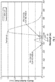
FIG. 1 illustrates the light spectra of conventional light sources in comparison to a predicted melatonin suppression action spectrum for polychromatic light. -
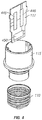
FIG. 2 is a perspective view of an LED lamp in accordance with one embodiment presented herein. -
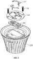
FIG. 3 is an exploded view of the LED lamp ofFIG. 2 . -
FIG. 4 is an exploded view of a portion of the LED lamp ofFIG. 2 . -
FIG. 5 is an exploded view of a portion of the LED lamp ofFIG. 2 . -
FIG. 6 is an exploded view of a portion of the LED lamp ofFIG. 2 . -
FIG. 7 is an exploded view of a portion of the LED lamp ofFIG. 2 . -
FIG. 8 is a schematic process diagram of an LED lamp in accordance with the present invention. -
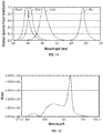
FIG. 9 illustrates a relative radiant power curve for a mint LED die used in one embodiment presented herein. -
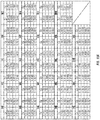
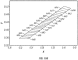
FIGs 10A and10B present color bin data for a mint LED die used III one embodiment presented herein. -
FIG. 1 1 shows relative spectral power distributions for red, cyan, and blue LED dies that are used in one embodiment presented. -
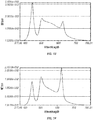
FIG. 12 shows a power spectral distribution of an LED lamp III a pre-sleep configuration, in accordance with another embodiment presented. -
FIG. 13 shows a power spectral distribution of an LED lamp in a phase-shift configuration, in accordance with one embodiment presented. -
FIG. 14 shows a power spectral distribution of an LED lamp in a general lighting configuration, in accordance with one embodiment presented. -
FIG. 15 is an exploded view of an LED lamp in accordance with another embodiment presented. -
FIG. 16 shows an alternative power spectral distribution for an LED lamp in a pre-sleep configuration. -
FIG. 17 shows an alternative power spectral distribution for an LED lamp in a phase-shift configuration. -
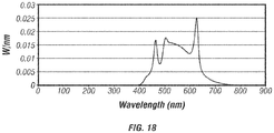
FIG. 18 shows an alternative power spectral distribution for an LED lamp in a general lighting configuration. - Melatonin is a hormone secreted at night by the pineal gland. Melatonin regulates sleep patterns and helps to maintain the body's circadian rhythm. The suppression of melatonin contributes to sleep disorders, disturbs the circadian rhythm, and may also contribute to conditions such as hypertension, heart disease, diabetes, and/or cancer. Blue light, and the blue light component of polychromatic light, have been shown to suppress the secretion of melatonin. Moreover, melatonin suppression has been shown to be wavelength dependent, and peak at wavelengths between about 420nm and about 480nm. As such, individuals who suffer from sleep disorders, or circadian rhythm disruptions, continue to aggravate their conditions when using polychromatic light sources that have a blue light (420nm-480nm) component.
- Curve A of
FIG. I illustrates the action spectrum for melatonin suppression. As shown by Curve A, a predicted maximum suppression is experienced at wavelengths around about 460nm. In other words, a light source having a spectral component between about 420nm and about 480nm is expected to cause melatonin suppression.FIG. 1 also illustrates the light spectra of conventional light sources. Curve B, for example, shows the light spectrum of an incandescent light source. As evidenced by Curve B, incandescent light sources cause low amounts of melatonin suppression because incandescent light sources lack a predominant blue component. Curve C, illustrating the light spectrum of a fluorescent light source, shows a predominant blue component. As such, fluorescent light sources are predicted to cause more melatonin suppression than incandescent light sources. Curve D, illustrating the light spectrum of a white light-emitting diode (LED) light source, shows a greater amount of blue component light than the fluorescent or incandescent light sources. As such, white LED light sources are predicted to cause more melatonin suppression than fluorescent or incandescent light sources. - As the once ubiquitous incandescent light bulb is replaced by fluorescent light sources (e.g., compact-fluorescent light bulbs) and white LED light sources, more individuals may begin to suffer from sleep disorders, circadian rhythm disorders, and other biological system disruptions. One solution may be to simply filter out all of the blue component (420nm-480nm) of a light source. However, such a simplistic approach would create a light source with unacceptable color rendering properties, and would negatively affect a user's photopic response.
- On the other hand, because exposure to light generally, and blue light in particular, can reduce the level of drowsiness by suppressing the secretion of melatonin, exposure to light can be employed to maintain alertness when needed. Additionally, exposure to enhanced blue light intensities can help to reset, or shift, the phase of the circadian rhythm of an individual. As such, phase-shifting can be useful in a variety of situations when resetting an individual's internal body clock is desired. Examples include: avoiding jet lag after inter-continental travel, or maintaining alertness for shift workers who are engaged in nighttime work. Although varying the intensity of the blue spectral component of a light source can be achieved through simple filtering, such filtering results in a non-optimal lighting environment.
- As such, presented herein is an LED lamp with commercially acceptable color rendering properties, which can be tuned to produce varying light outputs. In one embodiment, the light output produces minimal melatonin suppression, and thus has a minimal effect on natural sleep patterns and other biological systems. The LED lamp may also be tuned to generate different levels of blue light, appropriate for the given circumstance, while maintaining good light quality and a high CRI in each case. The LED lamp may also be configured to "self-tune" itself to generate the appropriate light output spectrum, depending on factors such as the lamp's location, use, ambient environment, etc.
- The light output states/configurations achievable by the LED lamps presented include: a pre-sleep configuration, a phase-shift configuration, and a general lighting configuration. In the pre-sleep configuration, the lamp generates a reduced level of blue light in order to provide an adequate working environment while significantly lessening the suppression of melatonin. The spectrum of light produced by the lamp in the pre-sleep configuration provides an environment appropriate for preparing for sleep while still maintaining light quality. In the phase-shifting configuration, the lamp generates an increased level of blue light, thereby greatly diminishing melatonin production. The spectrum of light produced by the lamp in this phase-shifting configuration provides an environment for shifting the phase of an individual's circadian rhythm or internal body clock. In the general lighting configuration, the lamp generates a normal level blue light, consistent with a typical light spectrum (e.g., daylight). In all states, however, the lamp maintains high visual qualities and CRI, in order to provide an adequate working environment.
- In one embodiment, the ability to tune, or adjust, the light output is provided by employing a specific combination of LED dies of different colors, and driving the LED dies at various currents to achieve the desired light output. In one embodiment, the LED lamp employs a combination of red, blue, cyan, and mint LED dies, such that the combination of dies produces a desired light output, while maintaining high quality light and high CRI.
- The following detailed description of the figures refers to the accompanying drawings that illustrate an exemplary embodiment of a tunable LED lamp for producing a biologically-adjusted light output. Other embodiments are possible. Modifications may be made to the embodiment described herein without departing from the spirit and scope of the present invention. Therefore, the following detailed description is not meant to be limiting.
-
FIG. 2 is a perspective view of an LED lamp (or bulb) 100 in accordance with one embodiment presented herein. In general,LED lamp 100 is appropriately designed to produce biologically-adjusted light, while still maintaining a commercially acceptable color temperature and commercially acceptable color rending properties. - The term "biologically-adjusted light" is intended to mean "a light that has been modified to manage biological effects on a user." The term "biological effects" is intended to mean "any impact or change a light source has to a naturally occurring function or process." Biological effects, for example, may include hormone secretion or suppression (e.g., melatonin suppression), changes to cellular function, stimulation or disruption of natural processes, cellular mutations or manipulations, etc.
- As shown in
FIG. 2 ,LED lamp 100 includes abase 1 10, aheat sink 120, and an optic 130. As will be described below,LED lamp 100 further includes one or more LED chips and dedicated circuitry. -
Base 1 10 is preferably an Edison-type screw-m shell.Base 1 10 is preferably formed of an electrically conductive material such as aluminum. In alternative embodiments,base 1 10 may be formed of other electrically conductive materials such as silver, copper, gold, conductive alloys, etc. Internal electrical leads (not shown) are attached tobase 1 10 to serve as contacts for a standard light socket (not shown). - As known in the art, the durability of an LED chip is usually affected by temperature. As such,
heat sink 120, and structures equivalent thereto, serves as means for dissipating heat away from one or more of the LED chips withinLED lamp 100. InFIG. 2 ,heat sink 120 includes fins to increase the surface area of the heat sink. Alternatively,heat sink 120 may be formed of any configuration, size, or shape, with the general intention of drawings heat away from the LED chips withinLED lamp 100.Heat sink 120 is preferably formed of a thermally conductive material such as aluminum, copper, steel, etc. -
Optic 130 is provided to surround the LED chips withinLED lamp 100. As used herein, the terms "surround" or "surrounding" are intended to mean partially or fully encapsulating. In other words, optic 130 surrounds the LED chips by partially or fully covering one or more LED chips such that light produced by one or more LED chips is transmitted throughoptic 130. In the embodiment shown, optic 130 takes a globular shape.Optic 130, however, may be formed of alternative forms, shapes, or sizes. In one embodiment, optic 130 serves as an optic diffusing element by incorporating diffusing technology, such as described inU.S. Patent No. 7,319,293 (which is incorporated herein by reference in its entirety). In such an embodiment, optic 130, and structures equivalent thereto, serves as a means for defusing light from the LED chips. In alternative embodiments, optic 130 may be formed of a light diffusive plastic, may include a light diffusive coating, or may having diffusive particles attached or embedded therein. - In one embodiment, optic 130 includes a color filter applied thereto. The color filter may be on the interior or exterior surface of
optic 130. The color filter is used to modify the light output from one or more of the LED chips. In one embodiment, the color filter is a ROSCOLUX #4530 CALCOLOR 30 YELLOW. In alternative embodiments, the color filter may be configured to have a total transmission of about 75%, a thickness of about 50 microns, and/or may be formed of a deep-dyed polyester film on a polyethylene terephthalate (PET) substrate. - In yet another embodiment, the color filter may be configured to have transmission percentages within +/-10%, at one or more wavelengths, in accordance with the following table:
-
FIG. 3 is an exploded view ofLED lamp 100, illustrating internal components of the lamp.FIGs. 4-7 are exploded views of portions ofLED lamp 100.FIGs. 3-7 also serve to illustrate how to assembleLED lamp 100. As shown, in addition to the components described above,LED lamp 100 also includes at least ahousing 1 15, a printed circuit board (PCB) 1 17, one ormore LED chips 200, aholder 125,spring wire connectors 127, and screws 129. - As described in more detail with reference to
FIG. 8 ,PCB 1 17 includes dedicated circuitry, such aspower supply 450,drive circuit 440, and output-select controller 445. The circuitry onPCB 1 17, and equivalents thereof, serves as a means for driving the LED chips 200 (or individual LED dies) to produce a biologically-adjusted light output. - As used herein, the term "LED chip(s)" is meant to broadly include LED die(s), with or without packaging and reflectors, that may or may not be treated (e.g., with applied phosphors). In the embodiment shown, however, each
LED chip 200 includes a plurality of LED dies. In one embodiment,LED chips 200 include an LED package comprising a plurality of LED dies, with at least two different colors, driven at varying currents to produce the desired light output and spectral power densities. Preferably, eachLED chip 200 includes two red LED dies, three cyan LED dies, four mint LED dies, and three blue LED dies.FIG. 9 illustrates a relative radiant power curve for a mint LED die used in one embodiment presented herein.FIGs. 10A and10B present color bin data for a mint LED die used in one embodiment presented herein.FIG. 1 1 shows relative spectral power distributions for red (or alternatively red-orange), cyan, and (two alternative) blue LED dies that are used in one embodiment presented (with alternative equivalent LED dies also being within the scope of the present invention). With this unique combinations of dies, together with the means for driving the LED chips, each of the above mentioned bio-effective states/configurations (e.g., pre-sleep, phase-shifting, and/or general lighting) can be obtained with good color rendering properties. - In one embodiment the tunable LED lamp operates in the pre-sleep configuration such that the radiant power emitted by the dies is in a ratio of: about 1 watt of radiant power generated by the mint LED dies, to about 0.5 watts of radiant power generated by the red-orange LED dies, to about 0.1 watts of radiant power generated by the cyan LED dies. In this embodiment the tunable LED lamp operates in the general lighting configuration such that the radiant power emitted by the dies is in a ratio about 1 watt of radiant power generated by the mint LED dies, to about 0.3 watts of radiant power generated by the red-orange LED dies, to about 0.4 watts of radiant power generated by the cyan LED dies, to about 0.2 watts of radiant power generated by the blue LED dies. In this embodiment, the tunable LED lamp operates in the phase-shift configuration such that the radiant power emitted by the dies is in a ratio of about 1 watt of radiant power generated by the mint LED dies, to about 0.1 watts of radiant power generated by the red-orange LED dies, to about .2 watts of radiant power generated by the cyan LED dies, to about 0.4 watts of radiant power generated by the blue LED dies.
- In another embodiment, the tunable LED lamp operates in the pre-sleep configuration such that the radiant power emitted by the dies is in a ratio of: about 1 watt of radiant power generated by the mint LED dies, to about 0.8 watts of radiant power generated by the red-orange LED dies, to about 0.3 watts of radiant power generated by the cyan LED dies. In this embodiment, the tunable LED lamp operates in the general lighting configuration such that the radiant power emitted by the dies is in a ratio about 1 watt of radiant power generated by the mint LED dies, to about 0.2 watts of radiant power generated by the red-orange LED dies, to about 0.2 watts of radiant power generated by the blue LED dies. In this embodiment, the tunable LED lamp operates in the phase-shift configuration such that the radiant power emitted by the dies is in a ratio of about 1 watt of radiant power generated by the mint LED dies, to about 0.1 watts of radiant power generated by the red-orange LED dies, to about 0.5 watts of radiant power generated by the blue LED dies.
- For example, to achieve a pre-sleep configuration,
drive circuit 440 may be configured to drive the plurality of LED dies such that a blue output intensity level, in a visible spectral output range of between about 380nm and about 485nm, is less than about 10% of a relative spectral power of any other peaks in the visible spectral output above about 485nm. In one embodiment,drive circuit 440 drives the plurality of LED dies such that about 150mA of current is delivered to four mint LED dies; about 360mA of current is delivered to two red LED dies; and about 40mA of current is delivered to three cyan LED dies. In another embodiment, wherein a color filter as described above is employed, the pre-sleep configuration is achieved by configuringdrive circuit 440 to deliver about 510MA of current to 4 mint LED dies. - To achieve a phase-shift configuration,
drive circuit 440 may be configured to drive the plurality of LED dies such that a blue output intensity level, in a visible spectral output range of between about 455nm and about 485nm, is greater than about 125% (or greater than aboutl50%; or greater than about 200%) of a relative spectral power of any other peaks in the visible spectral output above about 485nm. The color rendering index in the phase-shift configuration may be greater than 80. In one embodiment,drive circuit 440 drives the plurality of LED dies such that about 510mA of current is delivered to the mint LED dies; about 180mA of current is delivered to the red LED dies; about 40mA of current is delivered to the cyan LED dies; and about 100mA of current is delivered to the blue LED dies. - To achieve a general lighting configuration,
drive circuit 440 may be configured to drive the plurality of LED dies such that a blue output intensity level, in a visible spectral output range of between about 380nm and about 485nm, is between about 100% to about 20% of a relative spectral power of any other peaks in the visible spectral output above about 485nm. The color rendering index in the general lighting configuration may be greater than 85. In one embodiment,drive circuit 440 drives the plurality of LED dies such that about 450mA of current is delivered to the mint LED dies; about 230mA of current is delivered to the red LED dies; about 110mA of current is delivered to the cyan LED dies; and about 60mA of current is delivered to the blue LED die. - In one embodiment,
drive circuit 440 is configured to driveLED chips 200 with a ripple current at frequencies greater than 200Hz. A ripple current at frequencies above 200Hz is chosen to avoid biological effects that may be caused by ripple currents at frequencies below 200Hz. For example, studies have shown that some individuals are sensitive to light flicker below 200Hz, and in some instances experience aggravated headaches, seizures, etc. - As shown in
FIG. 4 ,base 1 10 is glued or crimped ontohousing 1 15.PCB 1 17 is mounted withinhousing 1 15. Insulation and/or potting compound (not shown) may be used to securePCB 1 17 withinhousing 1 15. Electrical leads onPCB 1 17 are coupled tobase 1 10 to form the electrical input leads ofLED lamp 100. - As shown in
FIG. 5 ,heat sink 120 is disposed abouthousing 1 15. As shown inFIG. 6 , twoLED chips 200 are mounted onto a support surface (or directly to heat sink 120), and maintained in place byholder 125. While twoLED chips 200 are shown, alternative embodiments may include any number of LED chips (i.e., one or more), or any number of LED dies individually mounted.Screws 129 are used to secureholder 125 toheat sink 120.Screws 129 may be any screws known in the art.Spring wire connectors 127 are used to connectLED chips 200 to thedrive circuit 440 onPCB 1 17. In an alternative embodiment, LED chips 200 (with or without packaging) may be attached directly toheat sink 120 without the use ofholder 125,screws 129, orconnectors 127. As shown inFIG. 7 ,optic 130 is then mounted on and attached toheat sink 120. -
FIG. 8 is a schematic process diagram of an LED lamp in accordance with the present invention.FIG. 8 also serves a depiction of the functional components mounted onPCB 1 17, or otherwise associated withLED lamp 100. In practice, apower supply 450 is used to provide power to drivecircuit 440.Power supply 450 may, for example, convert AC power to DC power, for driving the LED dies.Drive circuit 440 receives power input frompower supply 450, and directional input from output-select controller 445. In turn,drive circuit 440 provides the appropriate current supply to drive the LED dies in accordance with the desired spectral output.Controller 445 therefore serves to control the driving ofLEDs 200, and may control light output based on factors such as: time of day, ambient light, real time input, temperature, optical output, location of lamp, etc. Variations in temperature during operation can cause a spectral shift of individual dies. In an embodiment, a photo-sensor 860 is included to monitor the light output of theLEDs 200 to insure consistency and uniformity. Monitoring the output ofLEDs 200 allows for real time feedback and control of each die to maintain the desired output spectrum. Photo-sensor 860 may also be used to identify the ambient light conditions. Photo-sensor 860 thus provides an input tocontroller 445. - In another embodiment, a
thermal sensor 855 is used to measure the temperature of the LED dies and/or board supporting the LED dies. Because the light output of the dies is a known function of temperature, the measured temperature can be used to determine the light output of each die.Thermal sensor 855 may also be used to measure the ambient temperature conditions.Thermal sensor 855 thus provides another input tocontroller 445. - In another embodiment, a
GPS chip 870 and/orclock 875 is included and interfaced withcontroller 445. Because lamps are shipped around the world to their end location, the ability to determine the expected/actual ambient light, daily light cycle, and seasonal light cycle variations is important in any lamp that may generate light to stimulate or alter circadian rhythms.GPS chip 870 and/orclock 875 provide inputs intocontroller 445 such that the time of day, seasonality, and other factors can be taken into account bycontroller 445 to control the lamp output accordingly. For example, by knowing the time of day based on location, the pre-sleep spectrum of the lamp can be generated during the later hours of the day. - In still another embodiment, a user-
interface 865 is provided to allow a user to select the desired configuration. User-interface 865 may be in the form of a knob, switch, digital input, or equivalent means. As such, user-interface 865 provides an additional input tocontroller 445. - In one embodiment, the pre-sleep configuration spectrum includes a portion of the spectrum that is reduced (e.g., notched/troughed) in intensity. This trough is centered at about 470nm (or alternatively between about 470-480nm, between about 460-480nm, between about 470-490nm, or between about 460-490nm). Such wavelength ranges may be the most important contributor to, and most effective at, suppressing melatonin. Thus minimizing exposure in such wavelength bands during pre-sleep phase will be efficacious. In one embodiment, the notching of the pre-sleep spectrum is obtained using a phosphor-coated mint LED having a specific output spectrum to accomplish the notch in the pre-sleep spectrum. The mint LED itself may include a notch/trough with a minimum in the 470-480nm (or 460-490 nm range), and may be characterized by a maximum intensity in these wavelength ranges as a fractional percent of the peak intensity of the mint LED (e.g., the maximum of 470-480 emission is less than about 2.5% of the peak intensity; the max between about 460-490nm is less than about 5% of the peak intensity).
- With reference again to
FIG. 9 , illustrated is a relative radiant power curve for a mint LED die used in one embodiment presented. As used herein, the terms "mint LED" or "mint LED die" or "mint die" should be construed to include any LED source, LED chip, LED die (with or without photo-conversion material on the die), or any equivalent light source that is configured or capable of producing the relative radiant power curve shown inFIG. 9 , or a relative radiant power curve equivalent thereto. Of particular interest to the shown relative radiant power curve is the spectral "notch" between about 460-490nm, and more specifically between at about 470-480nm. Said spectral notch provides a relative intensity, with respect to the peak intensity, that allows the combination of LED dies (or equivalent light sources) to achieve their desired results (i.e., the desired output configuration). In one embodiment, the maximum intensity of the mint LED between about 460-490nm is less than about 5% of the peak intensity. In alternative embodiments the maximum intensity of the mint LED between about 460490nm is less than about 7.5%, or about 10%, or about 15%, or about 20% of the peak intensity. Further, in one embodiment, the maximum intensity of the mint LED between about 470-480nm is less than about 2.5% of the peak intensity. In alternative embodiments, the maximum intensity of the mint LED between about 470-480nm is less than about 3.5%,5%, 10%, or 20% of the peak intensity. -
Figures 12 ,13, and 14 show the power spectral distributions corresponding respectively to the pre-sleep, phase-shift, and general illumination configurations of the LED lamp in accordance with one embodiment of the invention. The LED lamp in this embodiment comprises an LED board with a ratio of cyan, mint, red, and royal blue dies of 3:3:2: 1 respectively. The spectral output of the lamp according to each configuration is adjusted by generating radiant fluxes from multiple dies as described below. -
FIG. 12 shows a power spectral distribution of an LED lamp III a pre-sleep configuration, in accordance with another embodiment presented. The pre-sleep configuration shown inFIG. 13 is produced by an array of LED dies in the 3:3:2:1 ratio, driven as follows: (1) three cyan LEDs driven at 7.65V, 66mA, 0.16679 radiant flux; (2) three mint LEDs driven parallel at ll.13V, 95lmA, 1.8774 radiant flux; (3) two red-orange LEDs driven at 4.375V, 998mA, 0.96199 radiant flux; and (4) one royal blue LED driven at 2.582V, 30mA, 0.0038584 radiant flux. The total luminous flux is l.024e+003 1 m. The total radiant flux is 3.023ge+000 W. The dominant wavelength is 580.3 nm. The general CRI is 87.30. The color temperature is 2871 K. The 1931 Coordinates (2°) are x: 0.4649, y: 0.4429. The luminous power per radiant watt is 338 lumens per radiant watt. -
FIG. 13 shows a power spectral distribution of an LED lamp in a phase-shift configuration, in accordance with one embodiment presented. The phase-shift configuration shown inFIG. 14 is produced by an array of LED dies in the 3:3:2:1 ratio, driven as follows: (1) three cyan LEDs driven at 8.19V, 235mA, 0.47233 radiant flux; (2) three mint LEDs driven parallel at 11.14V, 950mA, 1.9047 radiant flux; (3) two red-orange LEDs driven at 3.745V, 147mA, 0.1845 radiant flux; and (4) one royal blue LED driven at 2.802V, 525mA, 0.69093 radiant flux. The total luminous flux is 9.87ge+002 1 m. The total radiant flux is 3.2138e+000 W. The dominant wavelength is 495.6 nm. The peak wavelength is 449.7 nm. The general CRI is 87.42. The color temperature is 6,599 K. The 1931 Coordinates (2°) are x: 0.3092, y: 0.3406. The luminous power per radiant watt is 307 lumens per radiant watt. - In an alternative embodiment, in the phase-shift configuration, the intensity levels of blue component in the 455nm to 485nm range is preferably greater than about 125% of the relative spectral power of any other peaks in the visible light spectrum higher than 485nm. In alternative embodiments, the blue component in the 455nm to 485nm range may be is preferably greater than about 150%; or about 175%; or about 200%; or about 250%; or about 300% of the relative spectral power of any other peaks in the visible light spectrum higher than 485nm. The color rendering index is preferably greater than 80. By varying the radiant fluxes of one or more of the dies, for example by varying the current drawn by the dies, the intensity of the blue component relative to other spectral peaks greater than 485nm may be adjusted to the desired level.
-
FIG. 14 shows a power spectral distribution of an LED lamp in a general lighting configuration, in accordance with one embodiment presented. The general lighting configuration shown inFIG. 15 is produced by an array of LED dies in the 3::3:2:1 ratio, driven as follows: (1) three cyan LEDs driven at 8.22V, 21 1 mA, 0.44507 radiant flux; (2) three mint LEDs driven parallel at 10.06V, 499mA, 1 .1499 radiant flux; (3) two red-orange LEDs driven at 3.902V, 254mA, 0.34343 radiant flux; and (4) one blue LED driven at 2.712V, 190mA, 0.27280 radiant flux. The total luminous flux is 7.192e+002 1 m. The total radiant flux is 2.2248e+000 W. The dominant wavelength is 566.2 nm. The peak wavelength is 625.9 nm. The general CRI is 93.67. The color temperature is 4897 K. The 1931 Coordinates (2°) are x: 0.3516, y: 0.3874. The luminous power per radiant watt is 323 lumens per radiant watt. - In an alternative embodiment, in the general illumination configuration, the intensity levels of blue component in the 380nm to 485nm range is preferably about 100% of the relative spectral power of any other peaks in the visible light spectrum higher than 485nm. In alternative embodiments, the intensity levels of blue component in the 380nm to 485nm range is preferably less than about 100%; or less than about 90%; or less than about 80%; or between about 20% to about 100% of the relative spectral power of any other peaks in the visible light spectrum higher than 485nm. The color rendering index is preferably greater than 85.
-
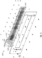
FIG. 15 is an exploded view of an LED lamp in accordance with another embodiment presented.FIG. 16 shows an additional form factor in which the present invention may be applied. For example,FIG. 16 shows alamp 1600 having an array ofLEDs 1610. TheLEDs 1610 may be provided in the 3:3:2:1 ratio of cyan:mint:red-orange:blue, as described above. - In another embodiment, the
LEDs 1610 may be provided in a 3:3:2:3 ratio of cyan:mint:red:blue, as described above. The LEDs are mounted on asupport frame 1620, which may serve as a heat-sink.LED circuitry 1630 is used to drive theLEDs 1610 with appropriate drive currents to achieve two or more output configurations (e.g., pre-sleep, phase-shift, and general lighting configurations). An output-select controller 1640 (and associated knob) are provided to allow an end-user to select the desired output configuration. An optic 1650 is provided in front of theLEDs 1610 to provide diffusive effects. The form factor may be completed by fastening the components with means such as screws and/or nuts and bolts, as shown. -
Figures 16, 17 , and18 show the power spectral distributions corresponding respectively to the pre-sleep, phase-shift, and general illumination configurations of the LED lamp in accordance with one embodiment of the invention. The LED lamp in this embodiment comprises an LED board with a ratio of cyan, mint, red, and blue dies of 3:3:2:3 respectively. The spectral output of the lamp according to each configuration is adjusted by generating radiant fluxes from multiple dies as described below. -
FIG. 16 shows a power spectral distribution of an LED lamp III a pre-sleep configuration, in accordance with another embodiment presented. The pre-sleep configuration shown inFIG. 13 is produced by an array of LED dies in the 3:3:2:3 ratio, driven as follows: (1) three cyan LEDs driven at 7.83V, 91 mA, to generate 0.2048 radiant watts; (2) three mint LEDs driven parallel at 9.42V, 288mA, 0.6345 radiant watts; (3) two red-orange LEDs driven at 4.077V, 490mA, 0.5434 radiant watts. The dominant wavelength is 581 .4 nm. The general CRI is 71. The color temperature is 2719 K. The luminous power per radiant watt is 331 lumens per radiant watt. The efficacy is 91 lumens per watt. -
FIG. 17 shows a power spectral distribution of an LED lamp in a phase-shift configuration, in accordance with another embodiment presented. The phase-shift configuration shown inFIG. 18 is produced by an array of LED dies in the 3:3:2:3 ratio, driven as follows: (1) three mint LEDs driven parallel at 1 1 .27V, 988mA, 1 .679 radiant watts; (2) two red-orange LEDs driven at 3.78V, 180mA, 1 .971 radiant, and (3) three blue LEDs driven at 9.07V, 296mA, 0.8719 radiant watts. The dominant wavelength is 476.9 nm. The general CRI is 88. The color temperature is 6235 K. The luminous power per radiant watt is 298 lumens per radiant watt. The efficacy is 63 lumens per watt. -
FIG. 18 shows a power spectral distribution of an LED lamp in a general lighting configuration, in accordance with another embodiment presented. The general lighting configuration shown in FIG. 19 is produced by an array of LED dies in the 3:3:2:3 ratio, driven as follows: (1) three cyan LEDs driven at 8.16V, 218mA, to generate 0.4332 radiant watts; (2) three mint LEDs driven parallel at 1 1 .23V, 972mA, 1 .869 radiant watts; (3) two red-orange LEDs driven at 3.89V, 295mA, 0.3520 radiant watts. The dominant wavelength is 565.6 nm. The general CRI is 90. The color temperature is 4828 K. The luminous power per radiant watt is 335 lumens per radiant watt. The efficacy is 68 lumens per watt - In another embodiment, there is provided a tunable LED lamp for producing a biologically-adjusted light output with a color rendering index above 70. The LED lamp comprises: a base; a housing attached to the base; a power circuit disposed within the housing and having electrical leads attached to the base; a drive circuit disposed within the housing and electrically coupled to the power circuit; and a heat sink disposed about the housing. The LED lamp further comprises: a plurality of LED dies mounted on a support coupled to the housing, wherein each of the plurality of LED dies is electrically coupled to and driven by the drive circuit. The plurality of LED dies includes two red LED dies, three cyan LED dies, four mint LED dies, and three blue LED dies. The LED lamp further comprises: an output-select controller electrically coupled to the drive circuit to program the drive circuit to drive the LED dies in one of a plurality of light output configurations. The plurality of light output configurations includes a pre-sleep configuration, a phase-shift configuration, and a general lighting configuration.
- The output-select controller may include a user-input interface allowing a user to select the light output configuration. The LED lamp my further include an input sensor electrically coupled to the output-select controller to provide an input variable for consideration in the selection of the light output configuration. The input sensor may be a thermal sensor, a photo-sensor, and/or a GPS chip. The input variable may be selected from the group consisting of: an ambient temperature, a support temperature, an LED die temperature, a housing temperature, the light output produced by the lamp, an ambient light, a daily light cycle, a location of the lamp, an expected ambient light, a seasonal light cycle variation, a time of day, and any combinations and/or equivalents thereof.
- In the pre-sleep configuration, the drive circuit drives the plurality of LED dies such that a blue output intensity level, in a visible spectral output range of between about 380nm and about 485nm, is less than about 10% of a relative spectral power of any other peaks in the visible spectral output above about 485nm. For example, the drive circuit may drive the plurality of LED dies such that about 150mA of current is delivered to the mint LED dies; about 360mA of current is delivered to the red LED dies; and about 40mA of current is delivered to the cyan LED dies.
- In the phase-shift configuration, the drive circuit drives the plurality of LED dies such that a blue output intensity level, in a visible spectral output range of between about 455nm and about 485nm, is greater than about 125% of a relative spectral power of any other peaks in the visible spectral output above about 485nm. The color rendering index in the phase-shift configuration may be greater than 80. For example, the drive circuit may drive the plurality of LED dies such that about 5lOmA of current is delivered to the mint LED dies; about 180mA of current is delivered to the red LED dies; about 40mA of current is delivered to the cyan LED dies; and about 100mA of current is delivered to the blue LED dies.
- In the general lighting configuration, the drive circuit drives the plurality of LED dies such that a blue output intensity level, in a visible spectral output range of between about 380nm and about 485nm, is between about 100% to about 20% of a relative spectral power of any other peaks in the visible spectral output above about 485nm. The color rendering index in the general lighting configuration may be greater than 85. For example, the drive circuit may drive the plurality of LED dies such that about 450mA of current is delivered to the mint LED dies; about 230mA of current is delivered to the red LED dies; about 1 10mA of current is delivered to the cyan LED dies; and about 60mA of current is delivered to the blue LED dies.
- In another embodiment, there is provided an LED lamp, comprising: a housing; a drive circuit disposed within the housing and configured to electrically couple to a power source; and a plurality of LED dies mounted on a support coupled to the housing, wherein each of the plurality of LED dies is electrically coupled to and driven by the drive circuit. The LED lamp further includes an output-select controller electrically coupled to the drive circuit to program the drive circuit to drive the LED dies in one of a plurality of light output configurations. The output-select controller may also include a user-input interface allowing a user to select the light output configuration.
- The plurality of light output configurations includes a pre-sleep configuration and a general lighting configuration. The plurality of light output configurations may further include a phase-shift configuration. The plurality of LED dies may include red LED dies, cyan LED dies, mint LED dies, and blue LED dies. The ratio of red LED dies to cyan LED dies to mint LED dies to blue LED dies of 2:3::3, respectively. The LED lamp may be tunable to produce a biologically-adjusted light output with a color rendering index above 70.
- The LED lamp may further comprise an input sensor electrically coupled to the output-select controller to provide an input variable for consideration in the selection of the light output configuration. The input sensor may be a thermal sensor, a photo-sensor, and/or a GPS chip. The input variable may be selected from the group consisting of: an ambient temperature, a support temperature, an LED die temperature, a housing temperature, the light output produced by the lamp, an ambient light, a daily light cycle, a location of the lamp, an expected ambient light, a seasonal light cycle variation, a time of day, and any combinations and/or equivalents thereof.
- In the pre-sleep configuration, the drive circuit drives the plurality of LED dies such that a blue output intensity level, in a visible spectral output range of between about 380nm and about 485nm, is less than about 10% of a relative spectral power of any other peaks in the visible spectral output above about 485nm. For example, the drive circuit may drive the plurality of LED dies such that about 150mA of current is delivered to the mint LED dies; about 360mA of current is delivered to the red LED dies; and about 40mA of current is delivered to the cyan LED dies.
- In the phase-shift configuration, the drive circuit drives the plurality of LED dies such that a blue output intensity level, in a visible spectral output range of between about 455nm and about 485nm, is greater than about 125% (or greater than about 150%; or greater than about 200%) of a relative spectral power of any other peaks in the visible spectral output above about 485nm. The color rendering index in the phase-shift configuration may be greater than 80. For example, the drive circuit may drive the plurality of LED dies such that about 510mA of current is delivered to the mint LED dies; about 180mA of current is delivered to the red LED dies; about 40mA of current is delivered to the cyan LED dies; and about 100mA of current is delivered to the blue LED dies
- In the general lighting configuration, the drive circuit drives the plurality of LED dies such that a blue output intensity level, in a visible spectral output range of between about 380nm and about 485nm, is between about 100% to about 20% of a relative spectral power of any other peaks in the visible spectral output above about 485nm. The color rendering index in the general lighting configuration may be greater than 85. For example, the drive circuit may drive the plurality of LED dies such that about 450mA of current is delivered to the mint LED dies; about 230mA of current is delivered to the red LED dies; about 1 10mA of current is delivered to the cyan LED dies; and about 60mA of current is delivered to the blue LED dies.
- In another embodiment, there is provided a tunable LED lamp for producing a biologically-adjusted light output with a color rendering index above 70, comprising: a base; a housing attached to the base; a power circuit disposed within the housing and having electrical leads attached to the base; a drive circuit disposed within the housing and electrically coupled to the power circuit; a heat sink disposed about the housing; a plurality of LED dies mounted on a support coupled to the housing, wherein each of the plurality of LED dies is electrically coupled to and driven by the drive circuit, and wherein the plurality of LED dies includes a ratio of two red-orange LED dies to three cyan LED dies to three mint LED dies to one blue LED dies; and an output-select controller electrically coupled to the drive circuit to program the drive circuit to drive the LED dies in one of a plurality of light output configurations, wherein the plurality of light output configurations includes a pre-sleep configuration, a phase-shift configuration, and a general lighting configuration. In the pre-sleep configuration, the drive circuit may drive the plurality of LED dies such that about 950mA of current is delivered to the mint LED dies, about 1 ,000mA of current is delivered to the red-orange LED dies, about 65mA of current is delivered to the cyan LED dies; and about 30mA of current is delivered to the blue LED dies. In the phase-shift configuration, the drive circuit may drive the plurality of LED dies such that about 950mA of current is delivered to the mint LED dies, about 150mA of current is delivered to the red-orange LED dies, about 235mA of current is delivered to the cyan LED dies, and about 525mA of current is delivered to the blue LED dies. In the general lighting configuration, the drive circuit may drive the plurality of LED dies such that about 500mA of current is delivered to the mint LED dies, about 250mA of current is delivered to the red-orange LED dies, about 210mA of current is delivered to the cyan LED dies, and about 190mA of current is delivered to the blue LED dies. In other embodiments, alternative currents may be delivered to vary the radiant fluxes and achieve the desired spectral output.
- In yet another embodiment, there is provided a method of manufacturing a tunable LED lamp for producing a biologically-adjusted light output with a color rendering index above 70. The method comprises: (a) attaching a base to a housing; (b) electrically coupling leads of a power circuit within the housing to the base; (c) electrically coupling a drive circuit disposed within the housing to the power circuit; (d) mounting a plurality of LED dies on a support coupled to the housing such that each of the plurality of LED dies is electrically coupled to and driven by the drive circuit, and wherein the plurality of LED dies includes two red LED dies, three cyan LED dies, four mint LED dies, and three blue LED dies; and (e) configuring the drive circuit to drive the LED dies in one of a plurality of light output configurations, wherein the plurality of light output configurations includes a pre-sleep configuration, a phase-shift configuration, and a general lighting configuration.
- The method may further comprise: (f) configuring the drive circuit to drive the plurality of LED dies such that a blue output intensity level, in a visible spectral output range of between about 380nm and about 485nm, is less than about 10% of a relative spectral power of any other peaks in the visible spectral output above about 485nm; (g) configuring the drive circuit to drive the plurality of LED dies such that a blue output intensity level, in a visible spectral output range of between about 455nm and about 485nm, is greater than about 125% of a relative spectral power of any other peaks in the visible spectral output above about 485nm; and/or (h) configuring the drive circuit to drive the plurality of LED dies such that a blue output intensity level, in a visible spectral output range of between about 380nm and about 485nm, is between about 100% to about 20% of a relative spectral power of any other peaks in the visible spectral output above about 485nm.
- The method may further comprise: (i) configuring the drive circuit to drive the plurality of LED dies such that about 150mA of current is delivered to the mint LED dies, about 360mA of current is delivered to the red LED dies, and about 40mA of current is delivered to the cyan LED dies; U) configuring the drive circuit to drive the plurality of LED dies such that about 510mA of current is delivered to the mint LED dies, about 180mA of current is delivered to the red LED dies, about 40mA of current is delivered to the cyan LED dies, and about 100mA of current is delivered to the blue LED dies; and/or (k) configuring the drive circuit to drive the plurality of LED dies such that about 450mA of current is delivered to the mint LED dies, about 230mA of current is delivered to the red LED dies, about 1 10mA of current is delivered to the cyan LED dies, and about 60mA of current is delivered to the blue LED dies.
- In another embodiment, there is provided an LED lamp, comprising: a housing; a drive circuit disposed within the housing and configured to electrically couple to a power source; a plurality of LED dies mounted on a support coupled to the housing, wherein each of the plurality of LED dies is electrically coupled to and driven by the drive circuit; and an output-select controller electrically coupled to the drive circuit to program the drive circuit to drive the LED dies in one of a plurality of light output configurations, wherein the plurality of light output configurations includes a pre-sleep configuration and a general lighting configuration. The plurality of LED dies includes red-orange LED dies, cyan LED dies, mint LED dies, and blue LED dies. The plurality of LED dies includes a ratio of red-orange LED dies to cyan LED dies to mint LED dies to blue LED dies of 2:3:3:1 , respectively.
- In another embodiment, there is provided a method of manufacturing a tunable LED lamp for producing a biologically-adjusted light output with a color rendering index above 70, comprising: attaching a base to a housing; electrically coupling leads of a power circuit within the housing to the base; electrically coupling a drive circuit disposed within the housing to the power circuit; mounting a plurality of LED dies on a support coupled to the housing such that each of the plurality of LED dies is electrically coupled to and driven by the drive circuit, and wherein the plurality of LED dies includes two red-orange LED dies, three cyan LED dies, three mint LED dies, and one blue LED dies; and configuring the drive circuit to drive the LED dies in one of a plurality of light output configurations, wherein the plurality of light output configurations includes a pre-sleep configuration, a phase-shift configuration, and a general lighting configuration. In the pre-sleep configuration the method may further comprises configuring the drive circuit to drive the plurality of LED dies such that about 950mA of current is delivered to the mint LED dies, about 1 ,000 mA of current is delivered to the red-orange LED dies, about 65mA of current is delivered to the cyan LED dies, and about 30mA of current is delivered to the blue LED dies. In the phase-shift configuration the method may further comprise: configuring the drive circuit to drive the plurality of LED dies such that about 950mA of current is delivered to the mint LED dies, about 150mA of current is delivered to the red LED dies, about 235mA of current is delivered to the cyan LED dies, and about 525mA of current is delivered to the blue LED dies. In the general lighting configuration the method may further comprise: configuring the drive circuit to drive the plurality of LED dies such that about 500mA of current is delivered to the mint LED dies, about 250mA of current is delivered to the red LED dies, about 210mA of current is delivered to the cyan LED dies, and about 190mA of current is delivered to the blue LED dies.
- It will be evident to those skilled in the art, that other die configuration or current schemes may be employed to achieve the desired spectral output of the LED lamp for producing biologically adjusted light.
- The foregoing description of the invention has been presented for purposes of illustration and description. It is not intended to be exhaustive or to limit the invention to the precise form disclosed. Other modifications and variations may be possible in light of the above teachings. The embodiments were chosen and described in order to best explain the principles of the invention and its practical application, and to thereby enable others skilled in the art to best utilize the invention in various embodiments and various modifications as are suited to the particular use contemplated. It is intended that the appended claims be construed to include other alternative embodiments of the invention; including equivalent structures, components, methods, and means.
- It is to be appreciated that the Detailed Description section, and not the Summary and Abstract sections, is intended to be used to interpret the claims. The Summary and Abstract sections may set forth one or more, but not all exemplary embodiments of the present invention as contemplated by the inventor(s), and thus, are not intended to limit the present invention and the appended claims in any way.
Claims (13)
- A tunable LED lamp (100) comprising:a housing (115);a drive circuit (440) disposed within the housing (115) and configured to electrically couple to a power source (450); anda plurality of LED dies mounted on a support coupled to the housing (115), wherein each of the plurality of LED dies is electrically coupled to and driven by the drive circuit (440);wherein the drive circuit (440) is operable to drive the LED dies in one of a plurality of light output configurations, wherein the plurality of light output configurations includes a pre-sleep configuration and a general lighting configuration;wherein in the pre-sleep configuration the drive circuit drives the plurality of LED dies such that a blue output intensity level, in a visible spectral output range of between about 380 nm and about 485 nm, is less than about 10% of a relative spectral power of any other peaks in the visible spectral output above about 485 nm,characterized in that the plurality of light output configurations further includes a phase-shift configuration, wherein in the phase-shift configuration, the drive circuit (440) drives the plurality of LED dies such that a blue output intensity level, in a visible spectral output range of between about 455 nm and about 485 nm, is greater than about 125% of a relative spectral power of any other peaks in the visible spectral output above about 485 nm.
- The tunable LED lamp (100) of Claim 1 wherein in the general lighting configuration, the drive circuit (440) drives the plurality of LED dies such that a blue output intensity level, in a visible spectral output range of between about 380 nm and about 485 nm, is between about 20% to about 100% of a relative spectral power of any other peaks in the visible spectral output above about 485 nm.
- The tunable LED lamp (100) of Claim 1 wherein one of the plurality of light output configurations produces a biologically-adjusted light output with a color rendering index above 70.
- The tunable LED lamp (100) of Claim 1 further comprising:an output-select controller (445) electrically coupled to the drive circuit to program the drive circuit to drive the LED dies in one of the plurality of light output configurations; andan input sensor (855, 860) electrically coupled to the output-select controller to provide an input variable for consideration in the selection of the light output configuration.
- The tunable LED lamp (100) of Claim 4 wherein the input sensor is a thermal sensor (855); and wherein the input variable is selected from the group consisting of an ambient temperature, a support temperature, an LED die temperature, a housing temperature, and any combination thereof.
- The tunable LED lamp (100) of Claim 4 wherein the input sensor is a photo-sensor (860); and wherein the input variable is selected from the group consisting of the light output produced by the lamp, an ambient light, a daily light cycle, and any combination thereof.
- The tunable LED lamp (100) of Claim 4 wherein the input sensor is a GPS chip; and wherein the input variable is selected from the group consisting of a location of the lamp, an expected ambient light, an actual ambient light, a daily light cycle, a seasonal light cycle variation, a time of day, and any combination thereof.
- The tunable LED lamp (100) of Claim 1, wherein in the phase-shift configuration, the drive circuit (440) drives the plurality of LED dies such that a blue output intensity level, in a visible spectral output range of between about 455 nm and about 485 nm, is between about 150% to 250% of a relative spectral power of any other peaks in the visible spectral output above about 485 nm.
- The tunable LED lamp (100) of Claim 1, wherein the plurality of LED dies includes a mint die, the power spectrum of which has a notch or trough in the 460-490 nm region.
- The tunable LED lamp (100) of Claim 9 wherein the mint die power spectrum has a notch or trough minimum centered near or about 470-475 nm.
- The tunable LED lamp (100) of Claim 9 wherein the mint die exhibits a power spectrum in which the maximum intensity of radiant power in the 470-480 nm range is less than about 2.5% of that of the peak intensity of the die.
- The tunable LED lamp (100) of Claim 1 wherein the plurality of LED dies includes red-orange LED dies, cyan LED dies, mint LED dies, and blue LED dies.
- The tunable LED lamp (100) of Claim 1, wherein the plurality of LED dies includes a ratio of red-orange LED dies to cyan LED dies to mint LED dies to blue LED dies of 2:3:3:3, respectively.
Applications Claiming Priority (3)
| Application Number | Priority Date | Filing Date | Title |
|---|---|---|---|
| US13/311,300 US8686641B2 (en) | 2011-12-05 | 2011-12-05 | Tunable LED lamp for producing biologically-adjusted light |
| PCT/US2012/067916 WO2013085978A2 (en) | 2011-12-05 | 2012-12-05 | Tunable led lamp for producing biologically-adjusted light |
| EP12813179.4A EP2788674B1 (en) | 2011-12-05 | 2012-12-05 | Tunable led lamp for producing biologically-adjusted light |
Related Parent Applications (2)
| Application Number | Title | Priority Date | Filing Date |
|---|---|---|---|
| EP12813179.4A Division EP2788674B1 (en) | 2011-12-05 | 2012-12-05 | Tunable led lamp for producing biologically-adjusted light |
| EP12813179.4A Division-Into EP2788674B1 (en) | 2011-12-05 | 2012-12-05 | Tunable led lamp for producing biologically-adjusted light |
Publications (2)
| Publication Number | Publication Date |
|---|---|
| EP3139081A1 EP3139081A1 (en) | 2017-03-08 |
| EP3139081B1 true EP3139081B1 (en) | 2019-06-12 |
Family
ID=47522911
Family Applications (2)
| Application Number | Title | Priority Date | Filing Date |
|---|---|---|---|
| EP16180625.2A Not-in-force EP3139081B1 (en) | 2011-12-05 | 2012-12-05 | Tunable led lamp for producing biologically-adjusted light |
| EP12813179.4A Active EP2788674B1 (en) | 2011-12-05 | 2012-12-05 | Tunable led lamp for producing biologically-adjusted light |
Family Applications After (1)
| Application Number | Title | Priority Date | Filing Date |
|---|---|---|---|
| EP12813179.4A Active EP2788674B1 (en) | 2011-12-05 | 2012-12-05 | Tunable led lamp for producing biologically-adjusted light |
Country Status (6)
| Country | Link |
|---|---|
| US (2) | US8686641B2 (en) |
| EP (2) | EP3139081B1 (en) |
| JP (1) | JP6283880B2 (en) |
| CN (2) | CN107588336B (en) |
| DK (1) | DK3139081T3 (en) |
| WO (1) | WO2013085978A2 (en) |
Families Citing this family (69)
| Publication number | Priority date | Publication date | Assignee | Title |
|---|---|---|---|---|
| US9827439B2 (en) | 2010-07-23 | 2017-11-28 | Biological Illumination, Llc | System for dynamically adjusting circadian rhythm responsive to scheduled events and associated methods |
| US8760370B2 (en) | 2011-05-15 | 2014-06-24 | Lighting Science Group Corporation | System for generating non-homogenous light and associated methods |
| US8841864B2 (en) | 2011-12-05 | 2014-09-23 | Biological Illumination, Llc | Tunable LED lamp for producing biologically-adjusted light |
| US8743023B2 (en) | 2010-07-23 | 2014-06-03 | Biological Illumination, Llc | System for generating non-homogenous biologically-adjusted light and associated methods |
| US9024536B2 (en) | 2011-12-05 | 2015-05-05 | Biological Illumination, Llc | Tunable LED lamp for producing biologically-adjusted light and associated methods |
| US9532423B2 (en) | 2010-07-23 | 2016-12-27 | Lighting Science Group Corporation | System and methods for operating a lighting device |
| US8686641B2 (en) | 2011-12-05 | 2014-04-01 | Biological Illumination, Llc | Tunable LED lamp for producing biologically-adjusted light |
| US8401231B2 (en) | 2010-11-09 | 2013-03-19 | Biological Illumination, Llc | Sustainable outdoor lighting system for use in environmentally photo-sensitive area |
| US9648284B2 (en) | 2011-05-15 | 2017-05-09 | Lighting Science Group Corporation | Occupancy sensor and associated methods |
| US9681108B2 (en) | 2011-05-15 | 2017-06-13 | Lighting Science Group Corporation | Occupancy sensor and associated methods |
| US9289574B2 (en) | 2011-12-05 | 2016-03-22 | Biological Illumination, Llc | Three-channel tuned LED lamp for producing biologically-adjusted light |
| US9913341B2 (en) | 2011-12-05 | 2018-03-06 | Biological Illumination, Llc | LED lamp for producing biologically-adjusted light including a cyan LED |
| US8963450B2 (en) | 2011-12-05 | 2015-02-24 | Biological Illumination, Llc | Adaptable biologically-adjusted indirect lighting device and associated methods |
| US8866414B2 (en) | 2011-12-05 | 2014-10-21 | Biological Illumination, Llc | Tunable LED lamp for producing biologically-adjusted light |
| US9220202B2 (en) | 2011-12-05 | 2015-12-29 | Biological Illumination, Llc | Lighting system to control the circadian rhythm of agricultural products and associated methods |
| US8878435B2 (en) * | 2012-01-26 | 2014-11-04 | Cree, Inc. | Remote thermal compensation assembly |
| DE102012205381A1 (en) * | 2012-04-02 | 2013-10-02 | Osram Gmbh | LED lighting device with mint and amber LEDs |
| US9006987B2 (en) | 2012-05-07 | 2015-04-14 | Lighting Science Group, Inc. | Wall-mountable luminaire and associated systems and methods |
| CN202660299U (en) * | 2012-05-23 | 2013-01-09 | 谢立栋 | Light-emitting diode (LED) induction lamp |
| TWI518278B (en) * | 2012-10-11 | 2016-01-21 | 隆達電子股份有限公司 | Lamp |
| US9174067B2 (en) | 2012-10-15 | 2015-11-03 | Biological Illumination, Llc | System for treating light treatable conditions and associated methods |
| US9347655B2 (en) | 2013-03-11 | 2016-05-24 | Lighting Science Group Corporation | Rotatable lighting device |
| US20140268731A1 (en) | 2013-03-15 | 2014-09-18 | Lighting Science Group Corpporation | Low bay lighting system and associated methods |
| US9468365B2 (en) * | 2013-03-15 | 2016-10-18 | Sanovas, Inc. | Compact light source |
| US9737195B2 (en) | 2013-03-15 | 2017-08-22 | Sanovas, Inc. | Handheld resector balloon system |
| WO2014165692A1 (en) | 2013-04-04 | 2014-10-09 | Circadian Management, Inc. | Lighting systems for protecting circadian neuroendocrine function |
| US20160131355A1 (en) * | 2013-06-10 | 2016-05-12 | Once Innovations, Inc. | Led lighting assembly and method of manufacturing the same |
| US9125271B2 (en) * | 2013-08-29 | 2015-09-01 | GE Lighting Solutions, LLC | Three-way lamp with programmable output levels |
| JP6112416B2 (en) * | 2013-09-06 | 2017-04-12 | パナソニックIpマネジメント株式会社 | Light irradiation device for body hair |
| CN103470985B (en) * | 2013-09-13 | 2015-04-15 | 浙江阳光照明电器集团股份有限公司 | LED bulb lamp |
| WO2015038962A1 (en) * | 2013-09-13 | 2015-03-19 | Konica Minolta Laboratory U.S.A., Inc. | Optimized power spectral distribution of light source |
| WO2015063644A1 (en) | 2013-10-28 | 2015-05-07 | Koninklijke Philips N.V. | Apparatus for controlling lighting parameters based on time of day and/or ambient light conditions and related methods |
| US9412253B2 (en) | 2014-02-06 | 2016-08-09 | Biological Illumination, Llc | System for detecting and analyzing motion for pattern prediction and associated methods |
| US20170189640A1 (en) * | 2014-06-25 | 2017-07-06 | Innosys, Inc. | Circadian Rhythm Alignment Lighting |
| CN109714863B (en) | 2014-09-16 | 2021-08-13 | 生物照明有限责任公司 | Illumination system for agricultural products |
| US10100987B1 (en) | 2014-09-24 | 2018-10-16 | Ario, Inc. | Lamp with directional, independently variable light sources |
| EP3882509A1 (en) * | 2014-10-14 | 2021-09-22 | Biological Illumination, LLC | Three-channel tuned led lamp for producing biologically-adjusted light |
| US10149439B2 (en) | 2014-12-18 | 2018-12-11 | Spectra Harvest Lighting, LLC | LED grow light system |
| CN104524682A (en) * | 2014-12-19 | 2015-04-22 | 苏州佳亿达电器有限公司 | LED lamp control system based on physiological rhythms of human body sleep |
| EP3271013B1 (en) | 2015-03-19 | 2018-08-22 | Philips Lighting Holding B.V. | Bio hue lamp |
| US9681510B2 (en) | 2015-03-26 | 2017-06-13 | Cree, Inc. | Lighting device with operation responsive to geospatial position |
| US9943042B2 (en) | 2015-05-18 | 2018-04-17 | Biological Innovation & Optimization Systems, LLC | Grow light embodying power delivery and data communications features |
| US9900957B2 (en) | 2015-06-11 | 2018-02-20 | Cree, Inc. | Lighting device including solid state emitters with adjustable control |
| TWI577042B (en) | 2015-07-15 | 2017-04-01 | 南臺科技大學 | Light emitting diode chip and data trasmission and recepition apparatus |
| US9844116B2 (en) | 2015-09-15 | 2017-12-12 | Biological Innovation & Optimization Systems, LLC | Systems and methods for controlling the spectral content of LED lighting devices |
| US9788387B2 (en) | 2015-09-15 | 2017-10-10 | Biological Innovation & Optimization Systems, LLC | Systems and methods for controlling the spectral content of LED lighting devices |
| CN105491720A (en) * | 2015-12-28 | 2016-04-13 | 华南理工大学 | Intelligent light emitting diode (LED) lighting system based on non-visual optical biological effect and lighting control method |
| WO2017155843A1 (en) * | 2016-03-11 | 2017-09-14 | Biological Illumination, Llc | Led lamp for producing biologically-adjusted light including a cyan led |
| US10004122B1 (en) | 2016-04-22 | 2018-06-19 | Ledvance Llc | Solid-state circadian rhythm lamp and related control techniques |
| US10595376B2 (en) | 2016-09-13 | 2020-03-17 | Biological Innovation & Optimization Systems, LLC | Systems and methods for controlling the spectral content of LED lighting devices |
| US10465869B2 (en) | 2017-01-30 | 2019-11-05 | Ideal Industries Lighting Llc | Skylight fixture |
| US10451229B2 (en) | 2017-01-30 | 2019-10-22 | Ideal Industries Lighting Llc | Skylight fixture |
| US10674579B2 (en) | 2018-01-26 | 2020-06-02 | Abl Ip Holding Llc | Lighting fixture with selectable color temperature |
| US10856384B2 (en) | 2018-05-29 | 2020-12-01 | Abl Ip Holding Llc | Lighting system with configurable color temperatures |
| US10448471B1 (en) | 2018-06-29 | 2019-10-15 | Abl Ip Holding Llc | Lighting system with configurable dimming |
| FR3083705A1 (en) * | 2018-07-11 | 2020-01-17 | Lucibel | DEVICE FOR ASSISTING THE SLEEPING OF A USER. |
| US10952292B2 (en) | 2018-08-09 | 2021-03-16 | Abl Ip Holding Llc | Programmable driver for variable light intensity |
| CN109513091B (en) * | 2018-12-26 | 2021-09-28 | 速眠创新科技(深圳)有限公司 | Sleep-aiding device and system |
| US10874006B1 (en) | 2019-03-08 | 2020-12-22 | Abl Ip Holding Llc | Lighting fixture controller for controlling color temperature and intensity |
| CN209672092U (en) * | 2019-03-14 | 2019-11-22 | 漳州立达信光电子科技有限公司 | A kind of LED lamp |
| US11259377B2 (en) | 2019-05-17 | 2022-02-22 | Abl Ip Holding Llc | Color temperature and intensity configurable lighting fixture using de-saturated color LEDs |
| CN112206422B (en) * | 2019-07-12 | 2022-07-01 | 周卓煇 | Method for suppressing melatonin secretion by light source and lighting device |
| MX2020010945A (en) | 2019-10-17 | 2021-04-19 | Abl Ip Holding Llc | Selectable lighting intensity and color temperature using luminaire lens. |
| WO2021092570A1 (en) * | 2019-11-08 | 2021-05-14 | EcoSense Lighting, Inc. | Dynamic display lighting systems with bioactive lighting |
| US11641708B2 (en) | 2020-08-28 | 2023-05-02 | Abl Ip Holding Llc | Light fixture controllable via dual networks |
| US11083061B1 (en) | 2020-10-16 | 2021-08-03 | Abl Ip Holding Llc | Systems to control light output characteristics of a lighting device |
| US11737396B2 (en) * | 2020-12-28 | 2023-08-29 | Seoul Viosys Co., Ltd. | Light module for plant cultivation and plant cultivation apparatus including the same |
| CN113766705A (en) * | 2021-04-30 | 2021-12-07 | 北京字节跳动网络技术有限公司 | Method and device for adjusting illumination parameters of table lamp, electronic equipment and storage medium |
| CN116557821B (en) * | 2023-07-10 | 2023-12-15 | 深圳市莎朗科技有限公司 | AI intelligent biological rhythm time light controller |
Family Cites Families (279)
| Publication number | Priority date | Publication date | Assignee | Title |
|---|---|---|---|---|
| US5046494A (en) | 1990-08-27 | 1991-09-10 | John Searfoss | Phototherapy method |
| GB9204798D0 (en) | 1992-03-05 | 1992-04-15 | Rank Brimar Ltd | Spatial light modulator system |
| US5221877A (en) | 1992-03-10 | 1993-06-22 | Davis Controls Corporation | Power reduction control for inductive lighting installation |
| US5680230A (en) | 1993-09-09 | 1997-10-21 | Canon Kabushiki Kaisha | Image processing method and apparatus thereof |
| US5523878A (en) | 1994-06-30 | 1996-06-04 | Texas Instruments Incorporated | Self-assembled monolayer coating for micro-mechanical devices |
| KR100449129B1 (en) | 1995-10-25 | 2005-01-24 | 인스트루먼츠 인코포레이티드 텍사스 | Investigation system |
| US6259572B1 (en) | 1996-02-21 | 2001-07-10 | Rosco Laboratories, Inc. | Photographic color effects lighting filter system |
| EP0851260A3 (en) | 1996-12-16 | 1998-09-09 | Ngk Insulators, Ltd. | Display device |
| WO1998037448A1 (en) | 1997-02-19 | 1998-08-27 | Digital Projection Limited | Illumination system |
| US5813753A (en) | 1997-05-27 | 1998-09-29 | Philips Electronics North America Corporation | UV/blue led-phosphor device with efficient conversion of UV/blues light to visible light |
| US6459919B1 (en) | 1997-08-26 | 2002-10-01 | Color Kinetics, Incorporated | Precision illumination methods and systems |
| US20040052076A1 (en) | 1997-08-26 | 2004-03-18 | Mueller George G. | Controlled lighting methods and apparatus |
| US20020113555A1 (en) | 1997-08-26 | 2002-08-22 | Color Kinetics, Inc. | Lighting entertainment system |
| US6528954B1 (en) | 1997-08-26 | 2003-03-04 | Color Kinetics Incorporated | Smart light bulb |
| US7598686B2 (en) | 1997-12-17 | 2009-10-06 | Philips Solid-State Lighting Solutions, Inc. | Organic light emitting diode methods and apparatus |
| US6027225A (en) | 1997-12-24 | 2000-02-22 | Martin; William E. | Battery powered light having solar and inductive charging means |
| AU747281B2 (en) | 1998-06-08 | 2002-05-09 | Karlheinz Strobl | Efficient light engine systems, components and methods of manufacture |
| US6290382B1 (en) | 1998-08-17 | 2001-09-18 | Ppt Vision, Inc. | Fiber bundle combiner and led illumination system and method |
| US7075707B1 (en) | 1998-11-25 | 2006-07-11 | Research Foundation Of The University Of Central Florida, Incorporated | Substrate design for optimized performance of up-conversion phosphors utilizing proper thermal management |
| US6140646A (en) | 1998-12-17 | 2000-10-31 | Sarnoff Corporation | Direct view infrared MEMS structure |
| TW455908B (en) | 1999-04-20 | 2001-09-21 | Koninkl Philips Electronics Nv | Lighting system |
| US6370168B1 (en) | 1999-10-20 | 2002-04-09 | Coherent, Inc. | Intracavity frequency-converted optically-pumped semiconductor laser |
| US7058197B1 (en) | 1999-11-04 | 2006-06-06 | Board Of Trustees Of The University Of Illinois | Multi-variable model for identifying crop response zones in a field |
| JP2001210116A (en) * | 2000-01-28 | 2001-08-03 | Matsushita Electric Works Ltd | Solar light collecting device |
| EP1283733A1 (en) | 2000-05-10 | 2003-02-19 | Thomas Jefferson University | Photoreceptor system for melatonin regulation and phototherapy |
| US6870523B1 (en) | 2000-06-07 | 2005-03-22 | Genoa Color Technologies | Device, system and method for electronic true color display |
| CN1168210C (en) | 2000-06-27 | 2004-09-22 | 百利通电子(上海)有限公司 | Infrared-induction electronic switch for lighting lamp |
| US6873450B2 (en) | 2000-08-11 | 2005-03-29 | Reflectivity, Inc | Micromirrors with mechanisms for enhancing coupling of the micromirrors with electrostatic fields |
| US6775048B1 (en) | 2000-10-31 | 2004-08-10 | Microsoft Corporation | Microelectrical mechanical structure (MEMS) optical modulator and optical display system |
| US20020151941A1 (en) | 2001-04-16 | 2002-10-17 | Shinichi Okawa | Medical illuminator, and medical apparatus having the medical illuminator |
| JP3940596B2 (en) | 2001-05-24 | 2007-07-04 | 松下電器産業株式会社 | Illumination light source |
| US7008559B2 (en) | 2001-06-06 | 2006-03-07 | Nomadics, Inc. | Manganese doped upconversion luminescence nanoparticles |
| IL159233A0 (en) | 2001-06-07 | 2004-06-01 | Genoa Technologies Ltd | Device, system and method of data conversion for wide gamut displays |
| US6734639B2 (en) | 2001-08-15 | 2004-05-11 | Koninklijke Philips Electronics N.V. | Sample and hold method to achieve square-wave PWM current source for light emitting diode arrays |
| US6594090B2 (en) | 2001-08-27 | 2003-07-15 | Eastman Kodak Company | Laser projection display system |
| JP2003091045A (en) | 2001-09-17 | 2003-03-28 | Mitsubishi Electric Corp | Lighting optical system and projection type display device |
| US6542671B1 (en) | 2001-12-12 | 2003-04-01 | Super Light Wave Corp. | Integrated 3-dimensional multi-layer thin-film optical couplers and attenuators |
| US7072096B2 (en) | 2001-12-14 | 2006-07-04 | Digital Optics International, Corporation | Uniform illumination system |
| EP1467414A4 (en) | 2001-12-29 | 2007-07-11 | Hangzhou Fuyang Xinying Dianzi | A led and led lamp |
| KR100474460B1 (en) | 2002-04-02 | 2005-03-08 | 삼성전자주식회사 | Apparatus for projection image |
| US6641283B1 (en) | 2002-04-12 | 2003-11-04 | Gelcore, Llc | LED puck light with detachable base |
| SE521058C3 (en) | 2002-05-21 | 2003-10-22 | Cellux Ab | Device for lighting and extinguishing lights on roads, tracks or other stretches |
| US6902296B2 (en) * | 2002-06-15 | 2005-06-07 | Searfoss, Iii Robert Lee | Nightlight for phototherapy |
| DE10233768A1 (en) | 2002-07-25 | 2004-02-12 | Philips Intellectual Property & Standards Gmbh | Lamp system with green-blue gas discharge lamp and yellow-red LED |
| US7748845B2 (en) | 2002-08-28 | 2010-07-06 | Robert Casper | Method and device for preventing alterations in circadian rhythm |
| ES2346648T3 (en) | 2002-08-28 | 2010-10-19 | Melcort Inc. | USE OF AN OPTICAL FILTER FOR THE PREVENTION OF THE SUPPRESSION OF MELATONIN BY LIGHT AT NIGHT. |
| US6945672B2 (en) | 2002-08-30 | 2005-09-20 | Gelcore Llc | LED planar light source and low-profile headlight constructed therewith |
| US20050218780A1 (en) | 2002-09-09 | 2005-10-06 | Hsing Chen | Method for manufacturing a triple wavelengths white LED |
| JP2006504253A (en) | 2002-09-30 | 2006-02-02 | テレダイン・ライティング・アンド・ディスプレイ・プロダクツ・インコーポレーテッド | Illuminator assembly |
| US6787999B2 (en) | 2002-10-03 | 2004-09-07 | Gelcore, Llc | LED-based modular lamp |
| US7015636B2 (en) | 2002-10-23 | 2006-03-21 | Charles Bolta | Balanced blue spectrum therapy lighting |
| US6762562B2 (en) | 2002-11-19 | 2004-07-13 | Denovo Lighting, Llc | Tubular housing with light emitting diodes |
| CN100352069C (en) | 2002-11-25 | 2007-11-28 | 松下电器产业株式会社 | LED illumination light source |
| JP2004184777A (en) | 2002-12-04 | 2004-07-02 | Nec Viewtechnology Ltd | Light source device and projection type display device |
| WO2004053385A2 (en) | 2002-12-11 | 2004-06-24 | Charles Bolta | Light emitting diode (l.e.d.) lighting fixtures with emergency back-up and scotopic enhancement |
| US6893140B2 (en) | 2002-12-13 | 2005-05-17 | W. T. Storey, Inc. | Flashlight |
| US7187484B2 (en) | 2002-12-30 | 2007-03-06 | Texas Instruments Incorporated | Digital micromirror device with simplified drive electronics for use as temporal light modulator |
| US6871982B2 (en) | 2003-01-24 | 2005-03-29 | Digital Optics International Corporation | High-density illumination system |
| US6767111B1 (en) | 2003-02-26 | 2004-07-27 | Kuo-Yen Lai | Projection light source from light emitting diodes |
| US7556406B2 (en) | 2003-03-31 | 2009-07-07 | Lumination Llc | Led light with active cooling |
| US7095053B2 (en) | 2003-05-05 | 2006-08-22 | Lamina Ceramics, Inc. | Light emitting diodes packaged for high temperature operation |
| EP1620676A4 (en) | 2003-05-05 | 2011-03-23 | Philips Solid State Lighting | Lighting methods and systems |
| US7157745B2 (en) | 2004-04-09 | 2007-01-02 | Blonder Greg E | Illumination devices comprising white light emitting diodes and diode arrays and method and apparatus for making them |
| US7528421B2 (en) | 2003-05-05 | 2009-05-05 | Lamina Lighting, Inc. | Surface mountable light emitting diode assemblies packaged for high temperature operation |
| US7633093B2 (en) | 2003-05-05 | 2009-12-15 | Lighting Science Group Corporation | Method of making optical light engines with elevated LEDs and resulting product |
| KR100943273B1 (en) | 2003-05-07 | 2010-02-23 | 삼성전자주식회사 | Method and apparatus for converting a 4-color, and organic electro-luminescent display device and using the same |
| EP1482721A1 (en) | 2003-05-26 | 2004-12-01 | Agfa-Gevaert AG | Device for detecting information contained in a phosphor layer |
| WO2005005299A1 (en) | 2003-06-10 | 2005-01-20 | Otis Elevator Company | Inductively coupled power, useful for wireless elevator hall fixtures |
| US7083304B2 (en) | 2003-08-01 | 2006-08-01 | Illumination Management Solutions, Inc. | Apparatus and method of using light sources of differing wavelengths in an unitized beam |
| JP4417700B2 (en) | 2003-09-19 | 2010-02-17 | 株式会社リコー | Lighting device |
| US7598961B2 (en) | 2003-10-21 | 2009-10-06 | Samsung Electronics Co., Ltd. | method and apparatus for converting from a source color space to a target color space |
| US7728846B2 (en) | 2003-10-21 | 2010-06-01 | Samsung Electronics Co., Ltd. | Method and apparatus for converting from source color space to RGBW target color space |
| US7605971B2 (en) | 2003-11-01 | 2009-10-20 | Silicon Quest Kabushiki-Kaisha | Plurality of hidden hinges for mircromirror device |
| US7289090B2 (en) | 2003-12-10 | 2007-10-30 | Texas Instruments Incorporated | Pulsed LED scan-ring array for boosting display system lumens |
| EP1704752A4 (en) | 2003-12-11 | 2009-09-23 | Philips Solid State Lighting | Thermal management methods and apparatus for lighting devices |
| US7034934B2 (en) | 2003-12-30 | 2006-04-25 | Neway Systems & Products, Inc. | Anti-carcinogenic lights and lighting |
| US20050267213A1 (en) | 2004-01-08 | 2005-12-01 | Dusa Pharmaceuticals, Inc. | Use of photodynamic therapy to enhance treatment with immuno-modulating agents |
| US7300177B2 (en) | 2004-02-11 | 2007-11-27 | 3M Innovative Properties | Illumination system having a plurality of light source modules disposed in an array with a non-radially symmetrical aperture |
| US7246923B2 (en) | 2004-02-11 | 2007-07-24 | 3M Innovative Properties Company | Reshaping light source modules and illumination systems using the same |
| US7427146B2 (en) | 2004-02-11 | 2008-09-23 | 3M Innovative Properties Company | Light-collecting illumination system |
| US7964883B2 (en) | 2004-02-26 | 2011-06-21 | Lighting Science Group Corporation | Light emitting diode package assembly that emulates the light pattern produced by an incandescent filament bulb |
| WO2005083493A1 (en) | 2004-02-27 | 2005-09-09 | Matsushita Electric Industrial Co., Ltd. | Illuminating light source and two-dimensional image display using same |
| WO2005089293A2 (en) | 2004-03-15 | 2005-09-29 | Color Kinetics Incorporated | Methods and systems for providing lighting systems |
| JP4121477B2 (en) | 2004-03-31 | 2008-07-23 | 三洋電機株式会社 | Illumination device and projection display device |
| US7215086B2 (en) | 2004-04-23 | 2007-05-08 | Lighting Science Group Corporation | Electronic light generating element light bulb |
| US7319293B2 (en) | 2004-04-30 | 2008-01-15 | Lighting Science Group Corporation | Light bulb having wide angle light dispersion using crystalline material |
| US7271034B2 (en) | 2004-06-15 | 2007-09-18 | International Business Machines Corporation | Semiconductor device with a high thermal dissipation efficiency |
| US20070291467A1 (en) | 2004-06-29 | 2007-12-20 | Hideo Nagai | Illumination Source |
| US20060002108A1 (en) | 2004-06-30 | 2006-01-05 | Ouderkirk Andrew J | Phosphor based illumination system having a short pass reflector and method of making same |
| US7255469B2 (en) | 2004-06-30 | 2007-08-14 | 3M Innovative Properties Company | Phosphor based illumination system having a light guide and an interference reflector |
| US7804098B2 (en) | 2004-06-30 | 2010-09-28 | Seoul Opto Device Co., Ltd. | Light emitting element with a plurality of cells bonded, method of manufacturing the same, and light emitting device using the same |
| US7252408B2 (en) | 2004-07-19 | 2007-08-07 | Lamina Ceramics, Inc. | LED array package with internal feedback and control |
| US7324076B2 (en) | 2004-07-28 | 2008-01-29 | Avago Technologies Ecbu Ip (Singapore) Pte. Ltd. | Methods and apparatus for setting the color point of an LED light source |
| US7684007B2 (en) | 2004-08-23 | 2010-03-23 | The Boeing Company | Adaptive and interactive scene illumination |
| TW200501464A (en) | 2004-08-31 | 2005-01-01 | Ind Tech Res Inst | LED chip structure with AC loop |
| US7144131B2 (en) | 2004-09-29 | 2006-12-05 | Advanced Optical Technologies, Llc | Optical system using LED coupled with phosphor-doped reflective materials |
| KR100672357B1 (en) | 2004-10-04 | 2007-01-24 | 엘지전자 주식회사 | LED suface emitting source and projection display system of the same |
| US7748877B1 (en) | 2004-10-05 | 2010-07-06 | Colby Steven M | Multi-mode bulb |
| US7573209B2 (en) | 2004-10-12 | 2009-08-11 | Koninklijke Philips Electronics N.V. | Method and system for feedback and control of a luminaire |
| KR100813959B1 (en) | 2004-10-19 | 2008-03-14 | 삼성전자주식회사 | Illuminator |
| US7042623B1 (en) | 2004-10-19 | 2006-05-09 | Reflectivity, Inc | Light blocking layers in MEMS packages |
| US7184201B2 (en) | 2004-11-02 | 2007-02-27 | Texas Instruments Incorporated | Digital micro-mirror device having improved contrast and method for the same |
| US7213926B2 (en) | 2004-11-12 | 2007-05-08 | Hewlett-Packard Development Company, L.P. | Image projection system and method |
| US7353859B2 (en) | 2004-11-24 | 2008-04-08 | General Electric Company | Heat sink with microchannel cooling for power devices |
| US20100096993A1 (en) * | 2004-11-29 | 2010-04-22 | Ian Ashdown | Integrated Modular Lighting Unit |
| US7325956B2 (en) | 2005-01-25 | 2008-02-05 | Jabil Circuit, Inc. | Light-emitting diode (LED) illumination system for a digital micro-mirror device (DMD) and method of providing same |
| US20060164005A1 (en) | 2005-01-25 | 2006-07-27 | Chuan-Sheng Sun | Illumination apparatus having adjustable color temperature and method for adjusting the color temperature |
| US7261453B2 (en) | 2005-01-25 | 2007-08-28 | Morejon Israel J | LED polarizing optics for color illumination system and method of using same |
| WO2006095949A1 (en) | 2005-03-11 | 2006-09-14 | Seoul Semiconductor Co., Ltd. | Led package having an array of light emitting cells coupled in series |
| JP5032749B2 (en) | 2005-03-16 | 2012-09-26 | パナソニック株式会社 | Optical filter and lighting device |
| US7382632B2 (en) | 2005-04-06 | 2008-06-03 | International Business Machines Corporation | Computer acoustic baffle and cable management system |
| US7906722B2 (en) | 2005-04-19 | 2011-03-15 | Palo Alto Research Center Incorporated | Concentrating solar collector with solid optical element |
| CN102063000B (en) | 2005-05-10 | 2014-08-06 | 岩崎电气株式会社 | Projector device, multilayer light-emitting diode device, and reflective light-emitting diode unit |
| CA2507177C (en) | 2005-05-13 | 2012-04-24 | Institut National D'optique | Image projector with flexible reflective analog modulator |
| JP4244957B2 (en) | 2005-05-19 | 2009-03-25 | カシオ計算機株式会社 | Light source device and projection device |
| KR101357475B1 (en) | 2005-05-31 | 2014-02-03 | 유니버셜 디스플레이 코포레이션 | Triphenylene hosts in phosphorescent light emitting diodes |
| JP2006337858A (en) | 2005-06-03 | 2006-12-14 | Fujifilm Holdings Corp | Optical modulation element array |
| US7434946B2 (en) | 2005-06-17 | 2008-10-14 | Texas Instruments Incorporated | Illumination system with integrated heat dissipation device for use in display systems employing spatial light modulators |
| JP4588571B2 (en) | 2005-06-28 | 2010-12-01 | セイコーインスツル株式会社 | Illumination device and display device including the same |
| CN101799126B (en) | 2005-06-28 | 2014-05-28 | 首尔伟傲世有限公司 | Light emitting device for AC power operation |
| US20070013871A1 (en) | 2005-07-15 | 2007-01-18 | Marshall Stephen W | Light-emitting diode (LED) illumination in display systems using spatial light modulators (SLM) |
| US7382091B2 (en) | 2005-07-27 | 2008-06-03 | Lung-Chien Chen | White light emitting diode using phosphor excitation |
| JP2007053065A (en) | 2005-08-19 | 2007-03-01 | Daiichi Shomei Kk | Medical lighting device |
| DE102005054955A1 (en) | 2005-08-31 | 2007-04-26 | Osram Opto Semiconductors Gmbh | Light-emitting module, in particular for use in a projection optical device and optical projection device |
| US7651227B2 (en) | 2005-09-13 | 2010-01-26 | Texas Instruments Incorporated | Projection system and method including spatial light modulator and compact diffractive optics |
| KR101333022B1 (en) | 2005-09-22 | 2013-11-26 | 코닌클리케 필립스 엔.브이. | Led lighting module and lighting assembly |
| US7429983B2 (en) | 2005-11-01 | 2008-09-30 | Cheetah Omni, Llc | Packet-based digital display system |
| US7369056B2 (en) | 2005-11-16 | 2008-05-06 | Hendrix Wire & Cable, Inc. | Photoelectric controller for electric street lighting |
| US7537347B2 (en) | 2005-11-29 | 2009-05-26 | Texas Instruments Incorporated | Method of combining dispersed light sources for projection display |
| US7855376B2 (en) | 2005-12-19 | 2010-12-21 | Institut National D'optique | Lighting system and method for illuminating and detecting object |
| US7540616B2 (en) | 2005-12-23 | 2009-06-02 | 3M Innovative Properties Company | Polarized, multicolor LED-based illumination source |
| US7342658B2 (en) | 2005-12-28 | 2008-03-11 | Eastman Kodak Company | Programmable spectral imaging system |
| GB2434260A (en) | 2006-01-11 | 2007-07-18 | Outside In | Phototherapy lights |
| US20070159492A1 (en) | 2006-01-11 | 2007-07-12 | Wintek Corporation | Image processing method and pixel arrangement used in the same |
| JP2007194950A (en) | 2006-01-19 | 2007-08-02 | Toshiba Corp | Projection type image display system, projection type image display device, and lamp lighting control method |
| US8441210B2 (en) | 2006-01-20 | 2013-05-14 | Point Somee Limited Liability Company | Adaptive current regulation for solid state lighting |
| US7832878B2 (en) | 2006-03-06 | 2010-11-16 | Innovations In Optics, Inc. | Light emitting diode projection system |
| JP4710690B2 (en) * | 2006-03-28 | 2011-06-29 | パナソニック電工株式会社 | Lighting equipment |
| KR100875443B1 (en) | 2006-03-31 | 2008-12-23 | 서울반도체 주식회사 | Light emitting device |
| US7834867B2 (en) | 2006-04-11 | 2010-11-16 | Microvision, Inc. | Integrated photonics module and devices using integrated photonics modules |
| US7889430B2 (en) | 2006-05-09 | 2011-02-15 | Ostendo Technologies, Inc. | LED-based high efficiency illumination systems for use in projection systems |
| US20070262714A1 (en) | 2006-05-15 | 2007-11-15 | X-Rite, Incorporated | Illumination source including photoluminescent material and a filter, and an apparatus including same |
| US7824075B2 (en) | 2006-06-08 | 2010-11-02 | Lighting Science Group Corporation | Method and apparatus for cooling a lightbulb |
| US7708452B2 (en) | 2006-06-08 | 2010-05-04 | Lighting Science Group Corporation | Lighting apparatus including flexible power supply |
| US20090128781A1 (en) | 2006-06-13 | 2009-05-21 | Kenneth Li | LED multiplexer and recycler and micro-projector incorporating the Same |
| DE102006027779A1 (en) | 2006-06-16 | 2007-12-20 | Robert Bosch Gmbh | Method for fixing an electrical or electronic component, in particular a printed circuit board, in a housing and fixing element therefor |
| DE102006037222A1 (en) * | 2006-08-09 | 2008-02-14 | Zumtobel Lighting Gmbh | Lamp with "melatonin-friendly" effect |
| KR101456727B1 (en) | 2006-08-23 | 2014-10-31 | 하이 퍼포먼스 옵틱스 인코퍼레이티드 | System and method for selective light inhibition |
| NZ575267A (en) | 2006-09-11 | 2011-12-22 | Comlight As | Control device, system and method for public illumination |
| KR100765240B1 (en) | 2006-09-30 | 2007-10-09 | 서울옵토디바이스주식회사 | Light emitting diode package having light emitting cell with different size and light emitting device thereof |
| US20080143973A1 (en) | 2006-10-12 | 2008-06-19 | Jing Miau Wu | Light source device of laser LED and projector having the same device |
| US20090027900A1 (en) | 2006-10-31 | 2009-01-29 | The L.D. Kichler Co. | Positionable outdoor lighting |
| EP1923922A1 (en) | 2006-11-15 | 2008-05-21 | Lemnis Lighting IP GmbH | Improved led lighting assembly |
| WO2008069101A1 (en) * | 2006-12-08 | 2008-06-12 | Sharp Kabushiki Kaisha | Light source, light source system and illumination device |
| WO2008069266A1 (en) | 2006-12-09 | 2008-06-12 | Murata Manufacturing Co., Ltd. | Piezoelectric micro-blower |
| US7766490B2 (en) | 2006-12-13 | 2010-08-03 | Philips Lumileds Lighting Company, Llc | Multi-color primary light generation in a projection system using LEDs |
| US7784972B2 (en) | 2006-12-22 | 2010-08-31 | Nuventix, Inc. | Thermal management system for LED array |
| US20110128742A9 (en) * | 2007-01-07 | 2011-06-02 | Pui Hang Yuen | High efficiency low cost safety light emitting diode illumination device |
| CN101583822A (en) | 2007-01-15 | 2009-11-18 | 阿尔卑斯电气株式会社 | Illuminating device, and input device having the former |
| US7771085B2 (en) | 2007-01-16 | 2010-08-10 | Steven Kim | Circular LED panel light |
| ITMI20070120A1 (en) | 2007-01-26 | 2008-07-27 | Piper Lux S R L | LED SPOTLIGHT |
| JP5086822B2 (en) | 2007-01-31 | 2012-11-28 | パナソニック株式会社 | Wavelength conversion device and two-dimensional image display device |
| US7633779B2 (en) | 2007-01-31 | 2009-12-15 | Lighting Science Group Corporation | Method and apparatus for operating a light emitting diode with a dimmer |
| TW200848783A (en) | 2007-02-15 | 2008-12-16 | Lamina Lighting Inc | High color rendering index white LED light system using multi-wavelength pump sources and mixed phosphors |
| US20080198572A1 (en) | 2007-02-21 | 2008-08-21 | Medendorp Nicholas W | LED lighting systems including luminescent layers on remote reflectors |
| US7619372B2 (en) | 2007-03-02 | 2009-11-17 | Lighting Science Group Corporation | Method and apparatus for driving a light emitting diode |
| US7972030B2 (en) | 2007-03-05 | 2011-07-05 | Intematix Corporation | Light emitting diode (LED) based lighting systems |
| EP2117648B1 (en) | 2007-03-09 | 2015-08-26 | Koninklijke Philips N.V. | Lighting system for energy stimulation |
| JP4839447B2 (en) | 2007-03-12 | 2011-12-21 | 国立大学法人山口大学 | Street light |
| KR20110110867A (en) | 2007-03-13 | 2011-10-07 | 서울옵토디바이스주식회사 | Ac light emitting diode |
| KR101396588B1 (en) | 2007-03-19 | 2014-05-20 | 서울반도체 주식회사 | Light emitting apparatus having various color temperature |
| JP2008235439A (en) | 2007-03-19 | 2008-10-02 | Nec Lighting Ltd | White light source device |
| US7976182B2 (en) | 2007-03-21 | 2011-07-12 | International Rectifier Corporation | LED lamp assembly with temperature control and method of making the same |
| US20080232116A1 (en) | 2007-03-22 | 2008-09-25 | Led Folio Corporation | Lighting device for a recessed light fixture |
| CN101542635B (en) | 2007-03-27 | 2013-01-23 | 株式会社东芝 | Scintillator panel and radiation detector |
| US8770821B2 (en) | 2007-04-16 | 2014-07-08 | Koninklijke Philips N.V. | Optical arrangement with a light transmitting layer arranged to cover a portion of light entry surface of light guide and to transmit light diffusively |
| WO2008136958A1 (en) | 2007-04-30 | 2008-11-13 | Opthera, Inc. | Uva1-led phototherapy device and method |
| ES2890714T3 (en) | 2007-05-04 | 2022-01-21 | Signify Holding Bv | LED-based luminaires and related procedures for thermal management |
| US7703943B2 (en) | 2007-05-07 | 2010-04-27 | Intematix Corporation | Color tunable light source |
| CN101678208B (en) | 2007-05-25 | 2013-07-17 | 皇家飞利浦电子股份有限公司 | A lighting system for creating a biological effect |
| US8410725B2 (en) | 2007-06-05 | 2013-04-02 | Koninklijke Philips Electronics N.V. | Lighting system for horticultural applications |
| US7719766B2 (en) | 2007-06-20 | 2010-05-18 | Texas Instruments Incorporated | Illumination source and method therefor |
| US7709811B2 (en) | 2007-07-03 | 2010-05-04 | Conner Arlie R | Light emitting diode illumination system |
| US20090036952A1 (en) | 2007-07-30 | 2009-02-05 | National Yang-Ming University | Induction driven light module and use thereof |
| KR101329125B1 (en) | 2007-08-13 | 2013-11-14 | 삼성전자주식회사 | Rgb to rgbw color decomposition method and system |
| US9374876B2 (en) | 2007-08-24 | 2016-06-21 | Martin A. Alpert | Multi-chip light emitting diode light device |
| WO2009029575A1 (en) * | 2007-08-24 | 2009-03-05 | Photonic Developments Llc | Light emitting diode lamp free of melatonin-suppressing radiation |
| KR100966374B1 (en) | 2007-08-27 | 2010-07-01 | 삼성엘이디 주식회사 | Plane light source using white LED and LCD backlight unit comprising the same |
| TWI383238B (en) | 2007-08-29 | 2013-01-21 | Young Optics Inc | Illumination system |
| CN101802571A (en) | 2007-09-11 | 2010-08-11 | 皇家飞利浦电子股份有限公司 | Ambient light compensation sensor and procedure |
| US7880400B2 (en) | 2007-09-21 | 2011-02-01 | Exclara, Inc. | Digital driver apparatus, method and system for solid state lighting |
| US7670021B2 (en) | 2007-09-27 | 2010-03-02 | Enertron, Inc. | Method and apparatus for thermally effective trim for light fixture |
| DE102007048115A1 (en) | 2007-10-05 | 2009-04-09 | Trilux Gmbh & Co. Kg | LED surgical light |
| US8662672B2 (en) | 2007-10-08 | 2014-03-04 | Koninklijke Philips N.V. | Lighting device, array of lighting devices and optical projection device |
| CN201119076Y (en) * | 2007-11-22 | 2008-09-17 | 汤锡强 | Timing start indoor lighting device |
| US7637643B2 (en) | 2007-11-27 | 2009-12-29 | Lighting Science Group Corporation | Thermal and optical control in a light fixture |
| US20090141506A1 (en) | 2007-12-03 | 2009-06-04 | Shih-Chi Lan | Illumination Device for Kitchen Hood |
| JP5280106B2 (en) | 2007-12-07 | 2013-09-04 | デクセリアルズ株式会社 | Light source device and display device |
| JP4740934B2 (en) * | 2007-12-07 | 2011-08-03 | シャープ株式会社 | Lighting device |
| EP2235434A4 (en) | 2007-12-24 | 2011-04-20 | Moore Benjamin & Co | System for representing colors including an integrating light capsule |
| WO2009092041A2 (en) | 2008-01-16 | 2009-07-23 | Abu-Ageel Nayef M | Illumination systems utilizing wavelength conversion materials |
| BRPI0906849B8 (en) * | 2008-01-17 | 2021-07-27 | Koninklijke Philips Nv | lighting device, and, method of providing a wake-up stimulus by means of a lighting device |
| US8337029B2 (en) | 2008-01-17 | 2012-12-25 | Intematix Corporation | Light emitting device with phosphor wavelength conversion |
| US8040070B2 (en) | 2008-01-23 | 2011-10-18 | Cree, Inc. | Frequency converted dimming signal generation |
| CA2652850A1 (en) | 2008-01-30 | 2009-07-30 | Canlyte Inc. | Transformer assembly and light fixture assembly using same |
| US7841714B2 (en) | 2008-02-07 | 2010-11-30 | Quantum Modulation Scientific Inc. | Retinal melatonin suppressor |
| US7984989B2 (en) | 2008-02-07 | 2011-07-26 | Gruber Jake A | Retinal melatonin suppressor comprising a filter layer |
| WO2009098621A1 (en) | 2008-02-08 | 2009-08-13 | Koninklijke Philips Electronics N.V. | Light module device |
| US8531126B2 (en) | 2008-02-13 | 2013-09-10 | Canon Components, Inc. | White light emitting apparatus and line illuminator using the same in image reading apparatus |
| WO2009101802A1 (en) | 2008-02-15 | 2009-08-20 | Panasonic Corporation | Color management module, color management device, integrated circuit, display device, and color management method |
| DE102008016756A1 (en) | 2008-03-31 | 2009-10-01 | Tridonicatco Schweiz Ag | Arrangement and method for controlling LEDs |
| US8319445B2 (en) | 2008-04-15 | 2012-11-27 | Boca Flasher, Inc. | Modified dimming LED driver |
| US8016443B2 (en) | 2008-05-02 | 2011-09-13 | Light Prescriptions Innovators, Llc | Remote-phosphor LED downlight |
| US8348492B2 (en) | 2008-05-06 | 2013-01-08 | Koninklijke Philips Electronics N.V. | Movable LED track luminaire |
| US8256921B2 (en) | 2008-05-16 | 2012-09-04 | Musco Corporation | Lighting system with combined directly viewable luminous or transmissive surface and controlled area illumination |
| WO2009150743A1 (en) | 2008-06-13 | 2009-12-17 | Necディスプレイソリューションズ株式会社 | Image display unit and method for displaying image |
| KR100924912B1 (en) | 2008-07-29 | 2009-11-03 | 서울반도체 주식회사 | Warm white light emitting apparatus and back light module comprising the same |
| CN201251048Y (en) * | 2008-07-31 | 2009-06-03 | 周国标 | Intelligent table lamp |
| US7922356B2 (en) | 2008-07-31 | 2011-04-12 | Lighting Science Group Corporation | Illumination apparatus for conducting and dissipating heat from a light source |
| KR101001241B1 (en) | 2008-09-05 | 2010-12-17 | 서울반도체 주식회사 | Ac led dimmer and dimming method thereby |
| KR20100030470A (en) | 2008-09-10 | 2010-03-18 | 삼성전자주식회사 | Light emitting device and system providing white light with various color temperatures |
| KR101519985B1 (en) | 2008-09-11 | 2015-05-15 | 삼성디스플레이 주식회사 | Light source module and display apparatus having the same |
| JP2010087393A (en) | 2008-10-02 | 2010-04-15 | Fujinon Corp | Light source device |
| JP2010092993A (en) * | 2008-10-06 | 2010-04-22 | Sharp Corp | Illuminating apparatus |
| US20100103389A1 (en) | 2008-10-28 | 2010-04-29 | Mcvea Kenneth Brian | Multi-MEMS Single Package MEMS Device |
| US8061857B2 (en) | 2008-11-21 | 2011-11-22 | Hong Kong Applied Science And Technology Research Institute Co. Ltd. | LED light shaping device and illumination system |
| JP5382849B2 (en) | 2008-12-19 | 2014-01-08 | パナソニック株式会社 | Light source device |
| US8083364B2 (en) | 2008-12-29 | 2011-12-27 | Osram Sylvania Inc. | Remote phosphor LED illumination system |
| WO2010090862A2 (en) | 2009-01-21 | 2010-08-12 | Abu-Ageel Nayef M | Illumination system utilizing wavelength conversion materials and light recycling |
| US8038314B2 (en) | 2009-01-21 | 2011-10-18 | Cooper Technologies Company | Light emitting diode troffer |
| US7828453B2 (en) | 2009-03-10 | 2010-11-09 | Nepes Led Corporation | Light emitting device and lamp-cover structure containing luminescent material |
| US8441214B2 (en) | 2009-03-11 | 2013-05-14 | Deloren E. Anderson | Light array maintenance system and method |
| US8310171B2 (en) | 2009-03-13 | 2012-11-13 | Led Specialists Inc. | Line voltage dimmable constant current LED driver |
| US20100244735A1 (en) | 2009-03-26 | 2010-09-30 | Energy Focus, Inc. | Lighting Device Supplying Temporally Appropriate Light |
| US9717120B2 (en) | 2009-04-24 | 2017-07-25 | City University Of Hong Kong | Apparatus and methods of operation of passive LED lighting equipment |
| US8427590B2 (en) | 2009-05-29 | 2013-04-23 | Soraa, Inc. | Laser based display method and system |
| US8410717B2 (en) * | 2009-06-04 | 2013-04-02 | Point Somee Limited Liability Company | Apparatus, method and system for providing AC line power to lighting devices |
| US8324840B2 (en) | 2009-06-04 | 2012-12-04 | Point Somee Limited Liability Company | Apparatus, method and system for providing AC line power to lighting devices |
| US8674613B2 (en) | 2009-06-22 | 2014-03-18 | Richard Landry Gray | Power reforming methods and associated multiphase lights |
| KR20120052983A (en) | 2009-08-14 | 2012-05-24 | 일리노이즈 툴 워크스 인코포레이티드 | Inductively powered lighting assembly |
| US20120201034A1 (en) | 2009-09-25 | 2012-08-09 | Chia-Mao Li | Wide-Range Reflective Structure |
| JP5824676B2 (en) * | 2009-09-29 | 2015-11-25 | パナソニックIpマネジメント株式会社 | LED illumination light source and illumination device |
| US8272763B1 (en) | 2009-10-02 | 2012-09-25 | Genesis LED Solutions | LED luminaire |
| US9028091B2 (en) | 2009-10-05 | 2015-05-12 | Lighting Science Group Corporation | Low profile light having elongated reflector and associated methods |
| US8864340B2 (en) | 2009-10-05 | 2014-10-21 | Lighting Science Group Corporation | Low profile light having concave reflector and associated methods |
| US8201968B2 (en) | 2009-10-05 | 2012-06-19 | Lighting Science Group Corporation | Low profile light |
| US8672518B2 (en) | 2009-10-05 | 2014-03-18 | Lighting Science Group Corporation | Low profile light and accessory kit for the same |
| CN101702421B (en) | 2009-10-23 | 2011-03-23 | 中外合资江苏稳润光电有限公司 | Manufacturing method of white light LED |
| US20110115381A1 (en) | 2009-11-18 | 2011-05-19 | Carlin Steven W | Modular led lighting system |
| US8172436B2 (en) | 2009-12-01 | 2012-05-08 | Ullman Devices Corporation | Rotating LED light on a magnetic base |
| US8740410B2 (en) | 2010-02-25 | 2014-06-03 | Lunera Lighting, Inc. | Troffer-style light fixture with cross-lighting |
| US8297798B1 (en) | 2010-04-16 | 2012-10-30 | Cooper Technologies Company | LED lighting fixture |
| JP2011258649A (en) | 2010-06-07 | 2011-12-22 | Sanken Electric Co Ltd | Lighting system and method for controlling the same |
| JP2012029276A (en) | 2010-06-21 | 2012-02-09 | Ricoh Co Ltd | Image forming device, color adjustment method and color adjustment program |
| US8324808B2 (en) | 2010-07-23 | 2012-12-04 | Biological Illumination, Llc | LED lamp for producing biologically-corrected light |
| US8841864B2 (en) | 2011-12-05 | 2014-09-23 | Biological Illumination, Llc | Tunable LED lamp for producing biologically-adjusted light |
| US8760370B2 (en) | 2011-05-15 | 2014-06-24 | Lighting Science Group Corporation | System for generating non-homogenous light and associated methods |
| US8465167B2 (en) | 2011-09-16 | 2013-06-18 | Lighting Science Group Corporation | Color conversion occlusion and associated methods |
| US8686641B2 (en) | 2011-12-05 | 2014-04-01 | Biological Illumination, Llc | Tunable LED lamp for producing biologically-adjusted light |
| US8253336B2 (en) | 2010-07-23 | 2012-08-28 | Biological Illumination, Llc | LED lamp for producing biologically-corrected light |
| US8547391B2 (en) | 2011-05-15 | 2013-10-01 | Lighting Science Group Corporation | High efficacy lighting signal converter and associated methods |
| US10883702B2 (en) | 2010-08-31 | 2021-01-05 | Ideal Industries Lighting Llc | Troffer-style fixture |
| US8227813B2 (en) | 2010-09-22 | 2012-07-24 | Bridgelux, Inc. | LED light source utilizing magnetic attachment |
| CN102444867A (en) * | 2010-10-13 | 2012-05-09 | 周卓辉 | Illuminating device capable of slowing down melatonin inhibiting phenomenon |
| CN101975345B (en) | 2010-10-28 | 2013-05-08 | 鸿富锦精密工业(深圳)有限公司 | LED (Light Emitting Diode) fluorescent lamp |
| US8401231B2 (en) | 2010-11-09 | 2013-03-19 | Biological Illumination, Llc | Sustainable outdoor lighting system for use in environmentally photo-sensitive area |
| US9494293B2 (en) | 2010-12-06 | 2016-11-15 | Cree, Inc. | Troffer-style optical assembly |
| US20120188769A1 (en) | 2011-01-20 | 2012-07-26 | Kenneth Lau | Induction lighting luminaire installation |
| US8384984B2 (en) | 2011-03-28 | 2013-02-26 | Lighting Science Group Corporation | MEMS wavelength converting lighting device and associated methods |
| US9316368B2 (en) | 2011-04-18 | 2016-04-19 | Cree, Inc. | LED luminaire including a thin phosphor layer applied to a remote reflector |
| US20120285667A1 (en) | 2011-05-13 | 2012-11-15 | Lighting Science Group Corporation | Sound baffling cooling system for led thermal management and associated methods |
| US10203088B2 (en) | 2011-06-27 | 2019-02-12 | Cree, Inc. | Direct and back view LED lighting system |
| US8752976B2 (en) | 2011-07-24 | 2014-06-17 | Cree, Inc. | Light fixture with co-formed plenum component |
| US10823347B2 (en) | 2011-07-24 | 2020-11-03 | Ideal Industries Lighting Llc | Modular indirect suspended/ceiling mount fixture |
| US8847436B2 (en) | 2011-09-12 | 2014-09-30 | Lighting Science Group Corporation | System for inductively powering an electrical device and associated methods |
| US8866414B2 (en) | 2011-12-05 | 2014-10-21 | Biological Illumination, Llc | Tunable LED lamp for producing biologically-adjusted light |
| US20140015438A1 (en) | 2012-05-06 | 2014-01-16 | Lighting Science Group Corporation | Tunable light system and associated methods |
| US9366409B2 (en) | 2012-05-06 | 2016-06-14 | Lighting Science Group Corporation | Tunable lighting apparatus |
| US8680457B2 (en) | 2012-05-07 | 2014-03-25 | Lighting Science Group Corporation | Motion detection system and associated methods having at least one LED of second set of LEDs to vary its voltage |
-
2011
- 2011-12-05 US US13/311,300 patent/US8686641B2/en active Active
-
2012
- 2012-12-05 WO PCT/US2012/067916 patent/WO2013085978A2/en active Application Filing
- 2012-12-05 CN CN201710860516.7A patent/CN107588336B/en not_active Expired - Fee Related
- 2012-12-05 EP EP16180625.2A patent/EP3139081B1/en not_active Not-in-force
- 2012-12-05 JP JP2014544998A patent/JP6283880B2/en not_active Expired - Fee Related
- 2012-12-05 CN CN201280059488.4A patent/CN104114932B/en not_active Expired - Fee Related
- 2012-12-05 DK DK16180625.2T patent/DK3139081T3/en active
- 2012-12-05 EP EP12813179.4A patent/EP2788674B1/en active Active
-
2014
- 2014-01-27 US US14/165,198 patent/US8941329B2/en not_active Expired - Fee Related
Non-Patent Citations (1)
| Title |
|---|
| None * |
Also Published As
| Publication number | Publication date |
|---|---|
| WO2013085978A2 (en) | 2013-06-13 |
| EP2788674A2 (en) | 2014-10-15 |
| CN107588336A (en) | 2018-01-16 |
| CN107588336B (en) | 2020-09-08 |
| CN104114932A (en) | 2014-10-22 |
| JP2015523671A (en) | 2015-08-13 |
| JP6283880B2 (en) | 2018-02-28 |
| US20130140988A1 (en) | 2013-06-06 |
| US8941329B2 (en) | 2015-01-27 |
| US8686641B2 (en) | 2014-04-01 |
| US20140217902A1 (en) | 2014-08-07 |
| WO2013085978A3 (en) | 2013-12-12 |
| CN104114932B (en) | 2017-10-20 |
| EP3139081A1 (en) | 2017-03-08 |
| EP2788674B1 (en) | 2016-08-31 |
| DK3139081T3 (en) | 2019-07-22 |
Similar Documents
| Publication | Publication Date | Title |
|---|---|---|
| EP3139081B1 (en) | Tunable led lamp for producing biologically-adjusted light | |
| US9024536B2 (en) | Tunable LED lamp for producing biologically-adjusted light and associated methods | |
| US9131573B2 (en) | Tunable LED lamp for producing biologically-adjusted light | |
| US9289574B2 (en) | Three-channel tuned LED lamp for producing biologically-adjusted light | |
| US8866414B2 (en) | Tunable LED lamp for producing biologically-adjusted light | |
| US9693414B2 (en) | LED lamp for producing biologically-adjusted light | |
| EP2596283B1 (en) | Led lamp for producing biologically-corrected light | |
| US9661715B2 (en) | Solid state light emitting devices including adjustable melatonin suppression effects | |
| US8253336B2 (en) | LED lamp for producing biologically-corrected light | |
| US8963450B2 (en) | Adaptable biologically-adjusted indirect lighting device and associated methods | |
| EP3882509A1 (en) | Three-channel tuned led lamp for producing biologically-adjusted light | |
| WO2017155843A1 (en) | Led lamp for producing biologically-adjusted light including a cyan led |
Legal Events
| Date | Code | Title | Description |
|---|---|---|---|
| PUAI | Public reference made under article 153(3) epc to a published international application that has entered the european phase |
Free format text: ORIGINAL CODE: 0009012 |
|
| STAA | Information on the status of an ep patent application or granted ep patent |
Free format text: STATUS: REQUEST FOR EXAMINATION WAS MADE |
|
| 17P | Request for examination filed |
Effective date: 20160721 |
|
| AC | Divisional application: reference to earlier application |
Ref document number: 2788674 Country of ref document: EP Kind code of ref document: P |
|
| AK | Designated contracting states |
Kind code of ref document: A1 Designated state(s): AL AT BE BG CH CY CZ DE DK EE ES FI FR GB GR HR HU IE IS IT LI LT LU LV MC MK MT NL NO PL PT RO RS SE SI SK SM TR |
|
| STAA | Information on the status of an ep patent application or granted ep patent |
Free format text: STATUS: EXAMINATION IS IN PROGRESS |
|
| 17Q | First examination report despatched |
Effective date: 20180104 |
|
| REG | Reference to a national code |
Ref country code: HK Ref legal event code: DE Ref document number: 1235846 Country of ref document: HK |
|
| RAP1 | Party data changed (applicant data changed or rights of an application transferred) |
Owner name: BIOLOGICAL ILLUMINATION, LLC Owner name: SOLER, ROBERT R. Owner name: BARTINE, DAVID E. Owner name: MAXIK, FREDRIC S. Owner name: GROVE, ELIZA KATAR |
|
| RIC1 | Information provided on ipc code assigned before grant |
Ipc: F21Y 113/10 20160101ALN20181129BHEP Ipc: F21K 9/23 20160101ALI20181129BHEP Ipc: A61M 21/02 20060101ALI20181129BHEP Ipc: F21Y 113/13 20160101ALN20181129BHEP Ipc: F21K 9/00 20160101AFI20181129BHEP Ipc: F21Y 115/10 20160101ALN20181129BHEP Ipc: H05B 33/08 20060101ALI20181129BHEP |
|
| RIC1 | Information provided on ipc code assigned before grant |
Ipc: F21Y 113/10 20160101ALN20181206BHEP Ipc: A61M 21/02 20060101ALI20181206BHEP Ipc: F21K 9/00 20160101AFI20181206BHEP Ipc: H05B 33/08 20060101ALI20181206BHEP Ipc: F21Y 113/13 20160101ALN20181206BHEP Ipc: F21Y 115/10 20160101ALN20181206BHEP Ipc: F21K 9/23 20160101ALI20181206BHEP |
|
| GRAP | Despatch of communication of intention to grant a patent |
Free format text: ORIGINAL CODE: EPIDOSNIGR1 |
|
| STAA | Information on the status of an ep patent application or granted ep patent |
Free format text: STATUS: GRANT OF PATENT IS INTENDED |
|
| INTG | Intention to grant announced |
Effective date: 20190122 |
|
| GRAS | Grant fee paid |
Free format text: ORIGINAL CODE: EPIDOSNIGR3 |
|
| GRAA | (expected) grant |
Free format text: ORIGINAL CODE: 0009210 |
|
| STAA | Information on the status of an ep patent application or granted ep patent |
Free format text: STATUS: THE PATENT HAS BEEN GRANTED |
|
| RAP1 | Party data changed (applicant data changed or rights of an application transferred) |
Owner name: BIOLOGICAL ILLUMINATION, LLC |
|
| AC | Divisional application: reference to earlier application |
Ref document number: 2788674 Country of ref document: EP Kind code of ref document: P |
|
| AK | Designated contracting states |
Kind code of ref document: B1 Designated state(s): AL AT BE BG CH CY CZ DE DK EE ES FI FR GB GR HR HU IE IS IT LI LT LU LV MC MK MT NL NO PL PT RO RS SE SI SK SM TR |
|
| REG | Reference to a national code |
Ref country code: GB Ref legal event code: FG4D |
|
| REG | Reference to a national code |
Ref country code: CH Ref legal event code: EP |
|
| REG | Reference to a national code |
Ref country code: AT Ref legal event code: REF Ref document number: 1143016 Country of ref document: AT Kind code of ref document: T Effective date: 20190615 |
|
| REG | Reference to a national code |
Ref country code: DE Ref legal event code: R096 Ref document number: 602012061056 Country of ref document: DE |
|
| REG | Reference to a national code |
Ref country code: IE Ref legal event code: FG4D |
|
| REG | Reference to a national code |
Ref country code: DK Ref legal event code: T3 Effective date: 20190718 |
|
| REG | Reference to a national code |
Ref country code: NL Ref legal event code: MP Effective date: 20190612 |
|
| REG | Reference to a national code |
Ref country code: LT Ref legal event code: MG4D |
|
| PG25 | Lapsed in a contracting state [announced via postgrant information from national office to epo] |
Ref country code: AL Free format text: LAPSE BECAUSE OF FAILURE TO SUBMIT A TRANSLATION OF THE DESCRIPTION OR TO PAY THE FEE WITHIN THE PRESCRIBED TIME-LIMIT Effective date: 20190612 Ref country code: SE Free format text: LAPSE BECAUSE OF FAILURE TO SUBMIT A TRANSLATION OF THE DESCRIPTION OR TO PAY THE FEE WITHIN THE PRESCRIBED TIME-LIMIT Effective date: 20190612 Ref country code: HR Free format text: LAPSE BECAUSE OF FAILURE TO SUBMIT A TRANSLATION OF THE DESCRIPTION OR TO PAY THE FEE WITHIN THE PRESCRIBED TIME-LIMIT Effective date: 20190612 Ref country code: FI Free format text: LAPSE BECAUSE OF FAILURE TO SUBMIT A TRANSLATION OF THE DESCRIPTION OR TO PAY THE FEE WITHIN THE PRESCRIBED TIME-LIMIT Effective date: 20190612 Ref country code: NO Free format text: LAPSE BECAUSE OF FAILURE TO SUBMIT A TRANSLATION OF THE DESCRIPTION OR TO PAY THE FEE WITHIN THE PRESCRIBED TIME-LIMIT Effective date: 20190912 Ref country code: LT Free format text: LAPSE BECAUSE OF FAILURE TO SUBMIT A TRANSLATION OF THE DESCRIPTION OR TO PAY THE FEE WITHIN THE PRESCRIBED TIME-LIMIT Effective date: 20190612 |
|
| PG25 | Lapsed in a contracting state [announced via postgrant information from national office to epo] |
Ref country code: RS Free format text: LAPSE BECAUSE OF FAILURE TO SUBMIT A TRANSLATION OF THE DESCRIPTION OR TO PAY THE FEE WITHIN THE PRESCRIBED TIME-LIMIT Effective date: 20190612 Ref country code: GR Free format text: LAPSE BECAUSE OF FAILURE TO SUBMIT A TRANSLATION OF THE DESCRIPTION OR TO PAY THE FEE WITHIN THE PRESCRIBED TIME-LIMIT Effective date: 20190913 Ref country code: LV Free format text: LAPSE BECAUSE OF FAILURE TO SUBMIT A TRANSLATION OF THE DESCRIPTION OR TO PAY THE FEE WITHIN THE PRESCRIBED TIME-LIMIT Effective date: 20190612 Ref country code: BG Free format text: LAPSE BECAUSE OF FAILURE TO SUBMIT A TRANSLATION OF THE DESCRIPTION OR TO PAY THE FEE WITHIN THE PRESCRIBED TIME-LIMIT Effective date: 20190912 |
|
| REG | Reference to a national code |
Ref country code: AT Ref legal event code: MK05 Ref document number: 1143016 Country of ref document: AT Kind code of ref document: T Effective date: 20190612 |
|
| PG25 | Lapsed in a contracting state [announced via postgrant information from national office to epo] |
Ref country code: AT Free format text: LAPSE BECAUSE OF FAILURE TO SUBMIT A TRANSLATION OF THE DESCRIPTION OR TO PAY THE FEE WITHIN THE PRESCRIBED TIME-LIMIT Effective date: 20190612 Ref country code: PT Free format text: LAPSE BECAUSE OF FAILURE TO SUBMIT A TRANSLATION OF THE DESCRIPTION OR TO PAY THE FEE WITHIN THE PRESCRIBED TIME-LIMIT Effective date: 20191014 Ref country code: SK Free format text: LAPSE BECAUSE OF FAILURE TO SUBMIT A TRANSLATION OF THE DESCRIPTION OR TO PAY THE FEE WITHIN THE PRESCRIBED TIME-LIMIT Effective date: 20190612 Ref country code: CZ Free format text: LAPSE BECAUSE OF FAILURE TO SUBMIT A TRANSLATION OF THE DESCRIPTION OR TO PAY THE FEE WITHIN THE PRESCRIBED TIME-LIMIT Effective date: 20190612 Ref country code: EE Free format text: LAPSE BECAUSE OF FAILURE TO SUBMIT A TRANSLATION OF THE DESCRIPTION OR TO PAY THE FEE WITHIN THE PRESCRIBED TIME-LIMIT Effective date: 20190612 Ref country code: NL Free format text: LAPSE BECAUSE OF FAILURE TO SUBMIT A TRANSLATION OF THE DESCRIPTION OR TO PAY THE FEE WITHIN THE PRESCRIBED TIME-LIMIT Effective date: 20190612 Ref country code: RO Free format text: LAPSE BECAUSE OF FAILURE TO SUBMIT A TRANSLATION OF THE DESCRIPTION OR TO PAY THE FEE WITHIN THE PRESCRIBED TIME-LIMIT Effective date: 20190612 |
|
| PG25 | Lapsed in a contracting state [announced via postgrant information from national office to epo] |
Ref country code: ES Free format text: LAPSE BECAUSE OF FAILURE TO SUBMIT A TRANSLATION OF THE DESCRIPTION OR TO PAY THE FEE WITHIN THE PRESCRIBED TIME-LIMIT Effective date: 20190612 Ref country code: IS Free format text: LAPSE BECAUSE OF FAILURE TO SUBMIT A TRANSLATION OF THE DESCRIPTION OR TO PAY THE FEE WITHIN THE PRESCRIBED TIME-LIMIT Effective date: 20191012 Ref country code: SM Free format text: LAPSE BECAUSE OF FAILURE TO SUBMIT A TRANSLATION OF THE DESCRIPTION OR TO PAY THE FEE WITHIN THE PRESCRIBED TIME-LIMIT Effective date: 20190612 Ref country code: IT Free format text: LAPSE BECAUSE OF FAILURE TO SUBMIT A TRANSLATION OF THE DESCRIPTION OR TO PAY THE FEE WITHIN THE PRESCRIBED TIME-LIMIT Effective date: 20190612 |
|
| REG | Reference to a national code |
Ref country code: DE Ref legal event code: R097 Ref document number: 602012061056 Country of ref document: DE |
|
| PG25 | Lapsed in a contracting state [announced via postgrant information from national office to epo] |
Ref country code: TR Free format text: LAPSE BECAUSE OF FAILURE TO SUBMIT A TRANSLATION OF THE DESCRIPTION OR TO PAY THE FEE WITHIN THE PRESCRIBED TIME-LIMIT Effective date: 20190612 |
|
| PLBE | No opposition filed within time limit |
Free format text: ORIGINAL CODE: 0009261 |
|
| STAA | Information on the status of an ep patent application or granted ep patent |
Free format text: STATUS: NO OPPOSITION FILED WITHIN TIME LIMIT |
|
| PG25 | Lapsed in a contracting state [announced via postgrant information from national office to epo] |
Ref country code: PL Free format text: LAPSE BECAUSE OF FAILURE TO SUBMIT A TRANSLATION OF THE DESCRIPTION OR TO PAY THE FEE WITHIN THE PRESCRIBED TIME-LIMIT Effective date: 20190612 |
|
| 26N | No opposition filed |
Effective date: 20200313 |
|
| PG25 | Lapsed in a contracting state [announced via postgrant information from national office to epo] |
Ref country code: SI Free format text: LAPSE BECAUSE OF FAILURE TO SUBMIT A TRANSLATION OF THE DESCRIPTION OR TO PAY THE FEE WITHIN THE PRESCRIBED TIME-LIMIT Effective date: 20190612 Ref country code: IS Free format text: LAPSE BECAUSE OF FAILURE TO SUBMIT A TRANSLATION OF THE DESCRIPTION OR TO PAY THE FEE WITHIN THE PRESCRIBED TIME-LIMIT Effective date: 20200224 |
|
| PG2D | Information on lapse in contracting state deleted |
Ref country code: IS |
|
| REG | Reference to a national code |
Ref country code: CH Ref legal event code: PL |
|
| REG | Reference to a national code |
Ref country code: BE Ref legal event code: MM Effective date: 20191231 |
|
| PG25 | Lapsed in a contracting state [announced via postgrant information from national office to epo] |
Ref country code: MC Free format text: LAPSE BECAUSE OF FAILURE TO SUBMIT A TRANSLATION OF THE DESCRIPTION OR TO PAY THE FEE WITHIN THE PRESCRIBED TIME-LIMIT Effective date: 20190612 |
|
| REG | Reference to a national code |
Ref country code: DE Ref legal event code: R082 Ref document number: 602012061056 Country of ref document: DE Representative=s name: TBK, DE Ref country code: DE Ref legal event code: R081 Ref document number: 602012061056 Country of ref document: DE Owner name: HEALTHE INC., MELBOURNE, US Free format text: FORMER OWNER: BIOLOGICAL ILLUMINATION, LLC, WEST WARWICK, RI, US |
|
| PG25 | Lapsed in a contracting state [announced via postgrant information from national office to epo] |
Ref country code: IE Free format text: LAPSE BECAUSE OF NON-PAYMENT OF DUE FEES Effective date: 20191205 Ref country code: LU Free format text: LAPSE BECAUSE OF NON-PAYMENT OF DUE FEES Effective date: 20191205 |
|
| PG25 | Lapsed in a contracting state [announced via postgrant information from national office to epo] |
Ref country code: LI Free format text: LAPSE BECAUSE OF NON-PAYMENT OF DUE FEES Effective date: 20191231 Ref country code: CH Free format text: LAPSE BECAUSE OF NON-PAYMENT OF DUE FEES Effective date: 20191231 Ref country code: BE Free format text: LAPSE BECAUSE OF NON-PAYMENT OF DUE FEES Effective date: 20191231 |
|
| PGFP | Annual fee paid to national office [announced via postgrant information from national office to epo] |
Ref country code: FR Payment date: 20201218 Year of fee payment: 9 Ref country code: DK Payment date: 20201218 Year of fee payment: 9 Ref country code: GB Payment date: 20201214 Year of fee payment: 9 |
|
| PG25 | Lapsed in a contracting state [announced via postgrant information from national office to epo] |
Ref country code: CY Free format text: LAPSE BECAUSE OF FAILURE TO SUBMIT A TRANSLATION OF THE DESCRIPTION OR TO PAY THE FEE WITHIN THE PRESCRIBED TIME-LIMIT Effective date: 20190612 |
|
| PGFP | Annual fee paid to national office [announced via postgrant information from national office to epo] |
Ref country code: DE Payment date: 20201229 Year of fee payment: 9 |
|
| PG25 | Lapsed in a contracting state [announced via postgrant information from national office to epo] |
Ref country code: HU Free format text: LAPSE BECAUSE OF FAILURE TO SUBMIT A TRANSLATION OF THE DESCRIPTION OR TO PAY THE FEE WITHIN THE PRESCRIBED TIME-LIMIT; INVALID AB INITIO Effective date: 20121205 Ref country code: MT Free format text: LAPSE BECAUSE OF FAILURE TO SUBMIT A TRANSLATION OF THE DESCRIPTION OR TO PAY THE FEE WITHIN THE PRESCRIBED TIME-LIMIT Effective date: 20190612 |
|
| PG25 | Lapsed in a contracting state [announced via postgrant information from national office to epo] |
Ref country code: MK Free format text: LAPSE BECAUSE OF FAILURE TO SUBMIT A TRANSLATION OF THE DESCRIPTION OR TO PAY THE FEE WITHIN THE PRESCRIBED TIME-LIMIT Effective date: 20190612 |
|
| REG | Reference to a national code |
Ref country code: DE Ref legal event code: R119 Ref document number: 602012061056 Country of ref document: DE |
|
| REG | Reference to a national code |
Ref country code: DK Ref legal event code: EBP Effective date: 20211231 |
|
| GBPC | Gb: european patent ceased through non-payment of renewal fee |
Effective date: 20211205 |
|
| PG25 | Lapsed in a contracting state [announced via postgrant information from national office to epo] |
Ref country code: GB Free format text: LAPSE BECAUSE OF NON-PAYMENT OF DUE FEES Effective date: 20211205 Ref country code: DE Free format text: LAPSE BECAUSE OF NON-PAYMENT OF DUE FEES Effective date: 20220701 |
|
| PG25 | Lapsed in a contracting state [announced via postgrant information from national office to epo] |
Ref country code: FR Free format text: LAPSE BECAUSE OF NON-PAYMENT OF DUE FEES Effective date: 20211231 |
|
| PG25 | Lapsed in a contracting state [announced via postgrant information from national office to epo] |
Ref country code: DK Free format text: LAPSE BECAUSE OF NON-PAYMENT OF DUE FEES Effective date: 20211231 |