EP3139024A1 - Method for producing water jacket spacer - Google Patents
Method for producing water jacket spacer Download PDFInfo
- Publication number
- EP3139024A1 EP3139024A1 EP15785220.3A EP15785220A EP3139024A1 EP 3139024 A1 EP3139024 A1 EP 3139024A1 EP 15785220 A EP15785220 A EP 15785220A EP 3139024 A1 EP3139024 A1 EP 3139024A1
- Authority
- EP
- European Patent Office
- Prior art keywords
- water jacket
- spacer
- jacket spacer
- producing
- side wall
- Prior art date
- Legal status (The legal status is an assumption and is not a legal conclusion. Google has not performed a legal analysis and makes no representation as to the accuracy of the status listed.)
- Granted
Links
Images




Classifications
-
- B—PERFORMING OPERATIONS; TRANSPORTING
- B29—WORKING OF PLASTICS; WORKING OF SUBSTANCES IN A PLASTIC STATE IN GENERAL
- B29C—SHAPING OR JOINING OF PLASTICS; SHAPING OF MATERIAL IN A PLASTIC STATE, NOT OTHERWISE PROVIDED FOR; AFTER-TREATMENT OF THE SHAPED PRODUCTS, e.g. REPAIRING
- B29C45/00—Injection moulding, i.e. forcing the required volume of moulding material through a nozzle into a closed mould; Apparatus therefor
- B29C45/0025—Preventing defects on the moulded article, e.g. weld lines, shrinkage marks
-
- B—PERFORMING OPERATIONS; TRANSPORTING
- B29—WORKING OF PLASTICS; WORKING OF SUBSTANCES IN A PLASTIC STATE IN GENERAL
- B29C—SHAPING OR JOINING OF PLASTICS; SHAPING OF MATERIAL IN A PLASTIC STATE, NOT OTHERWISE PROVIDED FOR; AFTER-TREATMENT OF THE SHAPED PRODUCTS, e.g. REPAIRING
- B29C37/00—Component parts, details, accessories or auxiliary operations, not covered by group B29C33/00 or B29C35/00
- B29C37/005—Compensating volume or shape change during moulding, in general
-
- B—PERFORMING OPERATIONS; TRANSPORTING
- B29—WORKING OF PLASTICS; WORKING OF SUBSTANCES IN A PLASTIC STATE IN GENERAL
- B29C—SHAPING OR JOINING OF PLASTICS; SHAPING OF MATERIAL IN A PLASTIC STATE, NOT OTHERWISE PROVIDED FOR; AFTER-TREATMENT OF THE SHAPED PRODUCTS, e.g. REPAIRING
- B29C45/00—Injection moulding, i.e. forcing the required volume of moulding material through a nozzle into a closed mould; Apparatus therefor
- B29C45/17—Component parts, details or accessories; Auxiliary operations
- B29C45/26—Moulds
- B29C45/27—Sprue channels ; Runner channels or runner nozzles
-
- B—PERFORMING OPERATIONS; TRANSPORTING
- B29—WORKING OF PLASTICS; WORKING OF SUBSTANCES IN A PLASTIC STATE IN GENERAL
- B29C—SHAPING OR JOINING OF PLASTICS; SHAPING OF MATERIAL IN A PLASTIC STATE, NOT OTHERWISE PROVIDED FOR; AFTER-TREATMENT OF THE SHAPED PRODUCTS, e.g. REPAIRING
- B29C45/00—Injection moulding, i.e. forcing the required volume of moulding material through a nozzle into a closed mould; Apparatus therefor
- B29C45/17—Component parts, details or accessories; Auxiliary operations
- B29C45/26—Moulds
- B29C45/27—Sprue channels ; Runner channels or runner nozzles
- B29C45/2701—Details not specific to hot or cold runner channels
- B29C45/2708—Gates
-
- B—PERFORMING OPERATIONS; TRANSPORTING
- B29—WORKING OF PLASTICS; WORKING OF SUBSTANCES IN A PLASTIC STATE IN GENERAL
- B29C—SHAPING OR JOINING OF PLASTICS; SHAPING OF MATERIAL IN A PLASTIC STATE, NOT OTHERWISE PROVIDED FOR; AFTER-TREATMENT OF THE SHAPED PRODUCTS, e.g. REPAIRING
- B29C45/00—Injection moulding, i.e. forcing the required volume of moulding material through a nozzle into a closed mould; Apparatus therefor
- B29C45/0025—Preventing defects on the moulded article, e.g. weld lines, shrinkage marks
- B29C2045/0027—Gate or gate mark locations
-
- B—PERFORMING OPERATIONS; TRANSPORTING
- B29—WORKING OF PLASTICS; WORKING OF SUBSTANCES IN A PLASTIC STATE IN GENERAL
- B29C—SHAPING OR JOINING OF PLASTICS; SHAPING OF MATERIAL IN A PLASTIC STATE, NOT OTHERWISE PROVIDED FOR; AFTER-TREATMENT OF THE SHAPED PRODUCTS, e.g. REPAIRING
- B29C45/00—Injection moulding, i.e. forcing the required volume of moulding material through a nozzle into a closed mould; Apparatus therefor
- B29C45/0025—Preventing defects on the moulded article, e.g. weld lines, shrinkage marks
- B29C2045/0034—Mould parting lines
-
- B—PERFORMING OPERATIONS; TRANSPORTING
- B29—WORKING OF PLASTICS; WORKING OF SUBSTANCES IN A PLASTIC STATE IN GENERAL
- B29C—SHAPING OR JOINING OF PLASTICS; SHAPING OF MATERIAL IN A PLASTIC STATE, NOT OTHERWISE PROVIDED FOR; AFTER-TREATMENT OF THE SHAPED PRODUCTS, e.g. REPAIRING
- B29C45/00—Injection moulding, i.e. forcing the required volume of moulding material through a nozzle into a closed mould; Apparatus therefor
- B29C2045/0086—Runner trees, i.e. several articles connected by a runner
-
- B—PERFORMING OPERATIONS; TRANSPORTING
- B29—WORKING OF PLASTICS; WORKING OF SUBSTANCES IN A PLASTIC STATE IN GENERAL
- B29C—SHAPING OR JOINING OF PLASTICS; SHAPING OF MATERIAL IN A PLASTIC STATE, NOT OTHERWISE PROVIDED FOR; AFTER-TREATMENT OF THE SHAPED PRODUCTS, e.g. REPAIRING
- B29C2793/00—Shaping techniques involving a cutting or machining operation
- B29C2793/009—Shaping techniques involving a cutting or machining operation after shaping
-
- B—PERFORMING OPERATIONS; TRANSPORTING
- B29—WORKING OF PLASTICS; WORKING OF SUBSTANCES IN A PLASTIC STATE IN GENERAL
- B29C—SHAPING OR JOINING OF PLASTICS; SHAPING OF MATERIAL IN A PLASTIC STATE, NOT OTHERWISE PROVIDED FOR; AFTER-TREATMENT OF THE SHAPED PRODUCTS, e.g. REPAIRING
- B29C33/00—Moulds or cores; Details thereof or accessories therefor
- B29C33/0061—Moulds or cores; Details thereof or accessories therefor characterised by the configuration of the material feeding channel
- B29C33/0066—Moulds or cores; Details thereof or accessories therefor characterised by the configuration of the material feeding channel with a subdivided channel for feeding the material to a plurality of locations
-
- B—PERFORMING OPERATIONS; TRANSPORTING
- B29—WORKING OF PLASTICS; WORKING OF SUBSTANCES IN A PLASTIC STATE IN GENERAL
- B29C—SHAPING OR JOINING OF PLASTICS; SHAPING OF MATERIAL IN A PLASTIC STATE, NOT OTHERWISE PROVIDED FOR; AFTER-TREATMENT OF THE SHAPED PRODUCTS, e.g. REPAIRING
- B29C45/00—Injection moulding, i.e. forcing the required volume of moulding material through a nozzle into a closed mould; Apparatus therefor
- B29C45/0053—Injection moulding, i.e. forcing the required volume of moulding material through a nozzle into a closed mould; Apparatus therefor combined with a final operation, e.g. shaping
- B29C45/006—Joining parts moulded in separate cavities
-
- B—PERFORMING OPERATIONS; TRANSPORTING
- B29—WORKING OF PLASTICS; WORKING OF SUBSTANCES IN A PLASTIC STATE IN GENERAL
- B29C—SHAPING OR JOINING OF PLASTICS; SHAPING OF MATERIAL IN A PLASTIC STATE, NOT OTHERWISE PROVIDED FOR; AFTER-TREATMENT OF THE SHAPED PRODUCTS, e.g. REPAIRING
- B29C45/00—Injection moulding, i.e. forcing the required volume of moulding material through a nozzle into a closed mould; Apparatus therefor
- B29C45/17—Component parts, details or accessories; Auxiliary operations
- B29C45/72—Heating or cooling
- B29C45/7207—Heating or cooling of the moulded articles
-
- B—PERFORMING OPERATIONS; TRANSPORTING
- B29—WORKING OF PLASTICS; WORKING OF SUBSTANCES IN A PLASTIC STATE IN GENERAL
- B29K—INDEXING SCHEME ASSOCIATED WITH SUBCLASSES B29B, B29C OR B29D, RELATING TO MOULDING MATERIALS OR TO MATERIALS FOR MOULDS, REINFORCEMENTS, FILLERS OR PREFORMED PARTS, e.g. INSERTS
- B29K2023/00—Use of polyalkenes or derivatives thereof as moulding material
- B29K2023/10—Polymers of propylene
- B29K2023/12—PP, i.e. polypropylene
-
- B—PERFORMING OPERATIONS; TRANSPORTING
- B29—WORKING OF PLASTICS; WORKING OF SUBSTANCES IN A PLASTIC STATE IN GENERAL
- B29K—INDEXING SCHEME ASSOCIATED WITH SUBCLASSES B29B, B29C OR B29D, RELATING TO MOULDING MATERIALS OR TO MATERIALS FOR MOULDS, REINFORCEMENTS, FILLERS OR PREFORMED PARTS, e.g. INSERTS
- B29K2077/00—Use of PA, i.e. polyamides, e.g. polyesteramides or derivatives thereof, as moulding material
-
- B—PERFORMING OPERATIONS; TRANSPORTING
- B29—WORKING OF PLASTICS; WORKING OF SUBSTANCES IN A PLASTIC STATE IN GENERAL
- B29K—INDEXING SCHEME ASSOCIATED WITH SUBCLASSES B29B, B29C OR B29D, RELATING TO MOULDING MATERIALS OR TO MATERIALS FOR MOULDS, REINFORCEMENTS, FILLERS OR PREFORMED PARTS, e.g. INSERTS
- B29K2081/00—Use of polymers having sulfur, with or without nitrogen, oxygen or carbon only, in the main chain, as moulding material
- B29K2081/04—Polysulfides, e.g. PPS, i.e. polyphenylene sulfide or derivatives thereof
-
- B—PERFORMING OPERATIONS; TRANSPORTING
- B29—WORKING OF PLASTICS; WORKING OF SUBSTANCES IN A PLASTIC STATE IN GENERAL
- B29L—INDEXING SCHEME ASSOCIATED WITH SUBCLASS B29C, RELATING TO PARTICULAR ARTICLES
- B29L2031/00—Other particular articles
- B29L2031/748—Machines or parts thereof not otherwise provided for
- B29L2031/749—Motors
-
- F—MECHANICAL ENGINEERING; LIGHTING; HEATING; WEAPONS; BLASTING
- F02—COMBUSTION ENGINES; HOT-GAS OR COMBUSTION-PRODUCT ENGINE PLANTS
- F02F—CYLINDERS, PISTONS OR CASINGS, FOR COMBUSTION ENGINES; ARRANGEMENTS OF SEALINGS IN COMBUSTION ENGINES
- F02F1/00—Cylinders; Cylinder heads
- F02F1/02—Cylinders; Cylinder heads having cooling means
- F02F1/10—Cylinders; Cylinder heads having cooling means for liquid cooling
- F02F1/14—Cylinders with means for directing, guiding or distributing liquid stream
Definitions
- the present invention relates to a method for producing a water jacket spacer that is assembled into the inside of a water jacket provided in a water-cooled internal combustion engine.
- a water jacket serving as a cooling water-circulating channel is formed around a bore wall of a cylinder bore. Normally, by inserting and assembling a spacer (water jacket spacer) into the inside of such a water jacket, flow of cooling water is controlled.
- Patent Document 1 proposes a method in which, in order to prevent deformation of a water jacket spacer in a post-molding cooling step without using a jig for correcting the shape, the opposing parts of the cylindrical main body of the spacer to be inserted into a water jacket are connected by a connecting bride, the shape of the spacer is retained after molding, and then the connecting bridge is cut off.
- Patent Document 1 JP-A-2005-105878
- a runner for introducing a molten resin into a gate is used as the connecting bridge.
- a mold piece forming the inner surface of a space 100 is allowed to be a split, and gate G is arranged at the parting line PL thereof.
- the present invention has been made taking the above circumferences into consideration, and is aimed at providing a method for producing a water jacket spacer in which, when producing by injection molding a water jacket spacer that is assembled into the inside of a water jacket and controls the flow of cooling water while producing with a high productivity without being affected by design constraints caused by draft angle, deformation in the post-molding cooling step can be prevented.
- the method for producing a water jacket spacer according to the present invention is a method for producing a water jacket spacer that is assembled into the inside of a water jacket provided in a water-cooled internal combustion engine in order to control the flow of cooling water, wherein the water jacket spacer has a side wall part in which a plurality of arc-like peripheral surface parts are connected through a waist part; a prescribed resin material is injection molded by using a molding die for injection molding in which resin flow channels are designed so that a plurality of gates are arranged along the longitudinal direction at a position corresponding to the outer peripheral surface of the side wall part; and after mold opening and ejecting, cooling is done while leaving a runner being connected to the gates, and thereafter, the runner is cut off.
- the present invention when producing a water jacket spacer by injection molding, while producing the water jacket spacer with a high productivity without being affected by design constraints caused by draft angle, deformation of the water jacket spacer in the post-molding cooling step can be prevented.
- a spacer 1 that is produced by the present embodiment is assembled into the inside of the water jacket WJ provided in a water-cooled inline-four engine for an automobile in which a cylinder block CBL and a cylinder head (not shown) are provided, and four cylinder bores CB arranged in series are formed in the cylinder block CBL.
- Fig. 3 is an explanatory view showing one example of a water-cooled internal combustion engine into which the spacer 1 is assembled.
- the spacer 1 is indicated by an alternate long and two short dashed line.
- the bore walls BW of a plurality (four in the shown example) of cylinder bores CB are formed such that they are connected to each other in a constricted manner between the adjacent cylinder bores CB to form an integral body, and, in the periphery of such bore wall BW, a water jacket WJ as the circulating channel for cooling water is formed.
- the spacer 1 has a shape that can be inserted into the inside of the water jacket WJ, and is formed such that it can extend along the bore wall BW having a constricted shape between the adjacent cylinder bores CB.
- the spacer 1 has a shape in which a plurality (four in the shown example) of cylindrical parts are integrally connected through waists part having the similar constricted shape in a hollow shape, the specific shape thereof is not particularly restricted.
- the spacer 1 can be appropriately designed such that, by assembling by insertion into the inside of the water jacket WJ, the spacer 1 controls the flow of cooling water that flows inside the water jacket WJ, whereby the temperature distribution of the bore wall BW can be optimized.
- it can have a shape that it is partially insertable into the inside of the water jacket WJ.
- the schematic shape of the spacer 1 produced in the present embodiment is shown in Fig. 1 and Fig. 2 .
- side wall parts 4 in which a plurality of arc-like peripheral surface parts 2 are connected adjacently through the waist part 3 are arranged opposingly, and are connected to arc-like end surface parts 5 at the both ends in the longitudinal direction.
- the spacer 1 having such a shape is molded by subjecting a prescribed resin material to injection molding by using an injection molding die in which a resin flow channel is designed such that a plurality of gates 6 serving as an inlet for a resin material to be filled in a cavity are arranged along the longitudinal direction at a position corresponding to the outer peripheral surface of the side wall part 4.
- the spacer is cooled while leaving the runners 7 that are continued to the gate 6 in the shape of the teeth of a comb. Thereafter, the runner 7 is cut off.
- the runner 7 connected to the outer peripheral surface of the side wall 4 of the spacer 1 in the shape of the teeth of a comb suppresses deformation of the spacer 1 in a softened state immediately after the ejection, whereby the shape of the spacer 1 during a period for which the spacer 1 is cooled and solidified can be retained.
- the runner 7 that is connected to the side wall part 4 of the spacer 1 in the shape of the teeth of a comb is cut off after the spacer 1 is fully solidified and there is no fear of deformation.
- the shape of the spacer 1 after the molding is retained. Since the gate 6 is arranged at a position corresponding to the outer peripheral surface of the side wall part, as shown in Fig. 4 , it is not necessary to allow the mold piece forming the inner peripheral surface of the spacer 1 to be a split. Therefore, draft angle of the inner peripheral surface of the spacer 1 can be a fixed angle along the mold-opening direction.
- Fig. 4 is a schematic view showing one example of a molding die used in the present embodiment.
- Fig. 5 is a schematic view showing an example in which the spacer 1 produced in the present embodiment is assembled to the water jacket WJ.
- burrs remaining in the spacer 1 after cutting the gate and burrs that are formed along the parting line PL are not formed on the inner peripheral surface side of the spacer 1, control thereof becomes facilitated.
- FIG. 6 Another example of the spacer 1 produced in the present embodiment is shown in Fig. 6 .
- a reinforcing part 7a in the shape of a brace can be formed.
- the gate 6 is arranged at a position corresponding to the middle of the height direction of the side wall part 4 of the spacer 1.
- the gate 6 is arranged at a position corresponding to the arc-like peripheral surface part 2 of the side wall part 4.
- the gate part 6 may be arranged at a position corresponding to the waist part 3 of the side wall part 4.
- the position at which the gate 6 is arranged can be appropriately designed in respect of molding properties taking into consideration flow of a resin.
- the gate 6 may be arranged at both a position corresponding to the arc-like peripheral surface part 2 and a position corresponding to the waist part 3 of the side wall part 4.
- a resin material In the present embodiment, no restrictions are imposed on a resin material.
- Polypropylene, polyamide, polyphenylsulfone or the like can be given, for example.
- a resin material that is excellent in heat resistance, moisture resistance, anti-freezer resistance, wear resistance or the like can be appropriately selected.
- the spacer 1 can have a shape that is partially insertable into the inside of the water jacket WJ.
- the spacer 1 when the spacer 1 is assembled to a part of the side from which cooling water is flown to the water jacket WJ and the spacer 1 is not assembled to the side from which the cooling water is discharged from the water jacket WJ, if the spacer 1 has a shape having the side wall part 4 in which a plurality of the arc-like peripheral surface parts 2 are connected through the waist part 3 (see Fig. 7 and Fig. 8 ), deformation of the spacer 1 having such a shape in the post-molding cooling step can be suppressed.
- the present invention can be applied to an inline multi-cylinder engine such as an inline-three engine.
- the present invention can be applied to a V-shaped engine and a horizontally-opposed engine. That is, the present invention can be widely applied to a water-cooled internal combustion engine provided with a water jacket.
- Figs. 9(a) to (d) each show a modification example in which the present invention is applied to an inline-three engine.
- side wall parts 4 in which three arc-like peripheral surface parts 2 are connected adjacently through the waist part 3 are arranged opposingly, and are connected to the arc-like end surface part 5 at the both ends in the longitudinal direction.
- Fig. 9(a) shows an example in which a gate is arranged along the longitudinal direction at a position corresponding to the arc-like peripheral surface part 2 of one of the side wall parts 4 arranged opposingly, and the runner 7 is connected to one of the side wall parts 4 in the form of the teeth of a comb.
- Fig. 9(b) shows an example in which the gate 6 is arranged along the longitudinal direction at a position corresponding to the arc-like peripheral surface part 2 of the both side wall parts 4 arranged opposingly, and the runner 7 is connected to the both side wall parts 4 in the shape of the teeth of a comb.
- Fig. 9(c) shows an example in which a gate is arranged along the longitudinal direction at a position corresponding to the waist part 3 of one of the side wall parts 4 arranged opposingly, and the runner 7 is connected to one of the side wall parts 4 in the shape of the teeth of a comb.
- Fig. 9(d) shows an example in which the gates 6 are arranged along the longitudinal direction at a position corresponding to the waist part 3 of both of the side wall parts 4 that are arranged opposingly, and the runner 7 is connected to the both side wall parts 4 in the shape of the teeth of a comb.
- Figs. 9(e) to (h) each show an example in which divided molded products 1 a are obtained by dividing the spacer 1 into two along the longitudinal direction, and the two divided molded products 1a are combined to obtain the spacer 1.
- Fig. 9(e) shows an example in which a gate is arranged along the longitudinal direction at a position corresponding to the outer peripheral surface of the arc-like peripheral surface part 2 of the side wall part 4 of the divided molded products 1 a, and the runner 7 is connected in the shape of the teeth of a comb.
- two divided molded products 1a can be obtained.
- Fig. 9(g) shows an example in which a gate is arranged along the longitudinal direction at a position corresponding to the arc-like peripheral surface part 2 of the both end sides of the side wall par 4 and at a position corresponding to the outer peripheral surface of the waist part 3 of the divided molded products 1 a, and the runner 7 is connected in the shape of the teeth of a comb.
- the two divided molded products 1 a can be obtained.
- the spacer 1 is obtained by combining the divided molded products 1a that are divided into two along the longitudinal direction.
- the spacer 1 may be obtained by combining a plurality of molded products divided at an arbitrary part.
- at least one divided molded body has a shape having the side wall part 4 in which a plurality of arc-like peripheral surface parts 2 are connected through the waist part 3, by applying the present invention, deformation of the divided molded products in the post-molding cooling step can be prevented.
- the spacer 1 is allowed to have a shape that is partially insertable into the inside of the water jacket WJ, by applying the present invention as in the case of the examples shown in Fig. 9(e) to (h) , deformation in the post-molding cooling step can be suppressed.
- the spacer 1 can be molded by using an injection molding die having a structure that molds the outer peripheral side of the side wall part 4 by a fixed mold and molds the inner peripheral side of the side wall part 4 by a movable mold.
- the gate 6 may be arranged at a position that corresponds to the both ends of the spacer 1. Also by doing so, there is no need to provide draft angle on the inner circumferential surface of the spacer 1.
- constraints caused by draft angle when designing the spacer 1 such that the temperature distribution of the bore wall BW can be optimized can be relaxed, and since burrs remaining in the spacer 1 after gate cutting and burrs that are formed along the parting line are also not formed on the inner peripheral surface side of the spacer 1, control thereof becomes facilitated. Further, when a gate cutting treatment is conducted, handling of tools used therefor is facilitated.
Landscapes
- Engineering & Computer Science (AREA)
- Manufacturing & Machinery (AREA)
- Mechanical Engineering (AREA)
- Moulds For Moulding Plastics Or The Like (AREA)
- Cylinder Crankcases Of Internal Combustion Engines (AREA)
- Injection Moulding Of Plastics Or The Like (AREA)
Abstract
Description
- The present invention relates to a method for producing a water jacket spacer that is assembled into the inside of a water jacket provided in a water-cooled internal combustion engine.
- In a water-cooled internal combustion engine such as a water-cooled engine for automobiles, a water jacket serving as a cooling water-circulating channel is formed around a bore wall of a cylinder bore. Normally, by inserting and assembling a spacer (water jacket spacer) into the inside of such a water jacket, flow of cooling water is controlled.
- Such a water jacket spacer is generally produced by injection molding by using a prescribed resin material.
Patent Document 1 proposes a method in which, in order to prevent deformation of a water jacket spacer in a post-molding cooling step without using a jig for correcting the shape, the opposing parts of the cylindrical main body of the spacer to be inserted into a water jacket are connected by a connecting bride, the shape of the spacer is retained after molding, and then the connecting bridge is cut off. - Patent Document 1:
JP-A-2005-105878 - However, in the method of
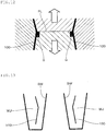
Patent Document 1, a runner for introducing a molten resin into a gate is used as the connecting bridge. As for the mold structure in this case, as shown inFig. 12 , a mold piece forming the inner surface of aspace 100 is allowed to be a split, and gate G is arranged at the parting line PL thereof. - By doing so, on the inner peripheral surface of the
spacer 100, taking mold opening into consideration, it is required to provide draft angle in which inclination direction is different in the opposite sides of the parting line PL along a mold opening direction shown by an arrow in the figure. Therefore, as shown inFig. 13 , when assembling thespacer 100 into the inside of the water jacket WJ, it becomes impossible to allow the inner peripheral surfaces of thespacer 100 to be opposed to the wall surface of the water jacket WJ along the inclination thereof. As a result, the gap between the upper side of the bore wall BW and thespacer 100 may be widened, etc., and the cooling water may be stagnated, resulting in lowering in cooling efficiency. Therefore, the shape of the spacer has to be designed taking constraints caused by draft angle into consideration. - Further, generally, in order to keep the bore wall warm, as for the gap between the wall surface of the water jacket and the spacer, in many cases, a gap formed on the inner peripheral side of the spacer when assembled into the water jacket is designed to be narrower than a gap formed on the outer peripheral side of the spacer. Therefore, in the method of
Patent Document 1, a problem arises that severe management is required to be conducted for burrs that remain on the inner surface of the spacer main body after gate cutting or for burrs that are formed along the parting line. - Further, when the connecting bridge that connects the opposing parts of the spacer main body is cut, tools for this cutting have to be inserted into the inside of the spacer main body, and as a result, handling of the tools has to be contrived in order that the tools do not interfere with the spacer main body.
- The present invention has been made taking the above circumferences into consideration, and is aimed at providing a method for producing a water jacket spacer in which, when producing by injection molding a water jacket spacer that is assembled into the inside of a water jacket and controls the flow of cooling water while producing with a high productivity without being affected by design constraints caused by draft angle, deformation in the post-molding cooling step can be prevented.
- The method for producing a water jacket spacer according to the present invention is a method for producing a water jacket spacer that is assembled into the inside of a water jacket provided in a water-cooled internal combustion engine in order to control the flow of cooling water, wherein
the water jacket spacer has a side wall part in which a plurality of arc-like peripheral surface parts are connected through a waist part;
a prescribed resin material is injection molded by using a molding die for injection molding in which resin flow channels are designed so that a plurality of gates are arranged along the longitudinal direction at a position corresponding to the outer peripheral surface of the side wall part; and
after mold opening and ejecting, cooling is done while leaving a runner being connected to the gates, and thereafter, the runner is cut off. - According to the present invention, when producing a water jacket spacer by injection molding, while producing the water jacket spacer with a high productivity without being affected by design constraints caused by draft angle, deformation of the water jacket spacer in the post-molding cooling step can be prevented.
-
-
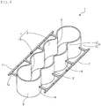
Fig. 1 is a perspective view showing an outline of one example of a water jacket spacer produced by the embodiment of the present invention; -
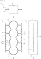
Fig. 2 is an explanatory view showing an outline of a water jacket spacer that is produced by the embodiment of the present invention, in which (a) is a plan view; (b) is a front view; and (c) is a side view; -
Fig. 3 is an explanatory view showing one example of an internal combustion engine to which a water jacket spacer that is produced by the embodiment of the present invention is assembled; -
Fig. 4 is a schematic view showing one example of a molding die used in the present embodiment; -
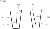
Fig. 5 is a schematic view showing an example in which a water jacket spacer that is produced by the embodiment of the present invention is assembled into a water jacket; -
Fig. 6 is a perspective view showing an outline of another example of a water jacket spacer that is produced by the embodiment of the present invention; -
Fig. 7 is a perspective view showing an outline of another example of a water jacket spacer that is produced by the embodiment of the present invention; -
Fig. 8 is a perspective view showing an outline of another example of a water jacket spacer that is produced by the embodiment of the present invention; -
Fig. 9 is an explanatory view showing a modification example of the present invention; -
Fig. 10 is an explanatory enlarged view of essential parts of a modification example of the present invention in which a gate is arranged at a waist part; -
Fig. 11 is an explanatory view showing a modification example of the present invention; -
Fig. 12 is a schematic view explaining problems associated with the conventional technology; and -
Fig. 13 is a schematic view explaining problems associated with the conventional technology. - Hereinbelow, an explanation will be made on the embodiment of the method for producing a water jacket spacer according to the present invention with reference to the drawings.
- As shown in
Fig. 3 , aspacer 1 that is produced by the present embodiment is assembled into the inside of the water jacket WJ provided in a water-cooled inline-four engine for an automobile in which a cylinder block CBL and a cylinder head (not shown) are provided, and four cylinder bores CB arranged in series are formed in the cylinder block CBL. -
Fig. 3 is an explanatory view showing one example of a water-cooled internal combustion engine into which thespacer 1 is assembled. InFig. 3 , thespacer 1 is indicated by an alternate long and two short dashed line. - In the cylinder block CBL, the bore walls BW of a plurality (four in the shown example) of cylinder bores CB are formed such that they are connected to each other in a constricted manner between the adjacent cylinder bores CB to form an integral body, and, in the periphery of such bore wall BW, a water jacket WJ as the circulating channel for cooling water is formed.
- The
spacer 1 has a shape that can be inserted into the inside of the water jacket WJ, and is formed such that it can extend along the bore wall BW having a constricted shape between the adjacent cylinder bores CB. Although, normally, thespacer 1 has a shape in which a plurality (four in the shown example) of cylindrical parts are integrally connected through waists part having the similar constricted shape in a hollow shape, the specific shape thereof is not particularly restricted. Thespacer 1 can be appropriately designed such that, by assembling by insertion into the inside of the water jacket WJ, thespacer 1 controls the flow of cooling water that flows inside the water jacket WJ, whereby the temperature distribution of the bore wall BW can be optimized. For example, in addition to the shape insertable along the entire circumference of the water jacket WJ, it can have a shape that it is partially insertable into the inside of the water jacket WJ. - The schematic shape of the
spacer 1 produced in the present embodiment is shown inFig. 1 andFig. 2 . In thespacer 1,side wall parts 4 in which a plurality of arc-likeperipheral surface parts 2 are connected adjacently through thewaist part 3 are arranged opposingly, and are connected to arc-likeend surface parts 5 at the both ends in the longitudinal direction. Thespacer 1 having such a shape is molded by subjecting a prescribed resin material to injection molding by using an injection molding die in which a resin flow channel is designed such that a plurality ofgates 6 serving as an inlet for a resin material to be filled in a cavity are arranged along the longitudinal direction at a position corresponding to the outer peripheral surface of theside wall part 4. - Then, after opening the injection molding die and ejecting the
molded spacer 1, the spacer is cooled while leaving therunners 7 that are continued to thegate 6 in the shape of the teeth of a comb. Thereafter, therunner 7 is cut off. - By doing so, the
runner 7 connected to the outer peripheral surface of theside wall 4 of thespacer 1 in the shape of the teeth of a comb suppresses deformation of thespacer 1 in a softened state immediately after the ejection, whereby the shape of thespacer 1 during a period for which thespacer 1 is cooled and solidified can be retained. Therunner 7 that is connected to theside wall part 4 of thespacer 1 in the shape of the teeth of a comb is cut off after thespacer 1 is fully solidified and there is no fear of deformation. - As mentioned above, in the present embodiment, by using the
runner 7 that is formed in the resin flow channel at the time of injection molding, the shape of thespacer 1 after the molding is retained. Since thegate 6 is arranged at a position corresponding to the outer peripheral surface of the side wall part, as shown inFig. 4 , it is not necessary to allow the mold piece forming the inner peripheral surface of thespacer 1 to be a split. Therefore, draft angle of the inner peripheral surface of thespacer 1 can be a fixed angle along the mold-opening direction. -
Fig. 4 is a schematic view showing one example of a molding die used in the present embodiment. - Therefore, when the
spacer 1 is assembled into the water jacket WJ, as shown inFig. 5 , the inner peripheral surfaces of thespacer 1 can be opposed to the wall of the water jacket WJ along the inclination thereof. As a result, flow of cooling water can be controlled smoothly without causing stagnation of the cooling water, whereby constraints caused by draft angle when designing thespacer 1 such that the temperature distribution of the bore wall BW can be optimized can be relaxed. -
Fig. 5 is a schematic view showing an example in which thespacer 1 produced in the present embodiment is assembled to the water jacket WJ. - Further, since burrs remaining in the
spacer 1 after cutting the gate and burrs that are formed along the parting line PL are not formed on the inner peripheral surface side of thespacer 1, control thereof becomes facilitated. - Further, since gate cutting is conducted on the outer peripheral surface side of the
spacer 1, handling of tools used therefor is facilitated. - As mentioned above, according to the present embodiment, when producing the
spacer 1 by injection molding, while producing thespacer 1 with a high productivity without being affected by design constraints caused by draft angle, deformation of thespacer 1 in the post-molding cooling step can be prevented. - Another example of the
spacer 1 produced in the present embodiment is shown inFig. 6 . When retaining the shape of thespacer 1 by therunner 7 connected to theside wall part 4 of thespacer 1 in the shape of the teeth of a comb, in the branched part of therunner 7, a reinforcingpart 7a in the shape of a brace can be formed. - Further, in the examples shown in
Fig. 1 andFig. 2 , thegate 6 is arranged at a position corresponding to the middle of the height direction of theside wall part 4 of thespacer 1. By doing so, deformation of thespacer 1 in the post-molding cooling step can be effectively prevented. As long as the shape of thespacer 1 can be retained, the position of theside wall 4 in the height direction at which thegate 6 is arranged is not restricted thereto. - In the examples shown in
Fig. 1 andFig. 2 , thegate 6 is arranged at a position corresponding to the arc-likeperipheral surface part 2 of theside wall part 4. By doing so, lowering in resin pressure hardly occurs in the vicinity of the outlet of thegate 6, and as a result, insufficient filling can be suppressed. On the other hand, there is a concern that insufficient flow such as formation of weld lines occurs in thewaist part 3. Therefore, when it is necessary to avoid occurrence of insufficient flow such as formation of weld lines in thewaist part 3, thegate part 6 may be arranged at a position corresponding to thewaist part 3 of theside wall part 4. The position at which thegate 6 is arranged can be appropriately designed in respect of molding properties taking into consideration flow of a resin. According to need, thegate 6 may be arranged at both a position corresponding to the arc-likeperipheral surface part 2 and a position corresponding to thewaist part 3 of theside wall part 4. - In the present embodiment, no restrictions are imposed on a resin material. Polypropylene, polyamide, polyphenylsulfone or the like can be given, for example. A resin material that is excellent in heat resistance, moisture resistance, anti-freezer resistance, wear resistance or the like can be appropriately selected.
- As mentioned above, the
spacer 1 can have a shape that is partially insertable into the inside of the water jacket WJ. For example, when thespacer 1 is assembled to a part of the side from which cooling water is flown to the water jacket WJ and thespacer 1 is not assembled to the side from which the cooling water is discharged from the water jacket WJ, if thespacer 1 has a shape having theside wall part 4 in which a plurality of the arc-likeperipheral surface parts 2 are connected through the waist part 3 (seeFig. 7 andFig. 8 ), deformation of thespacer 1 having such a shape in the post-molding cooling step can be suppressed. - Hereinabove, the present invention has been explained with reference to the preferable embodiment. However, the present invention is not restricted to the above-mentioned preferable embodiment, and it is needless to say that various modifications are possible within the scope of the present invention.
- For example, in the above-mentioned embodiment, an explanation was made taking as an example a water jacket spacer used in a water-cooled inline-four engine for an automobile. The present invention can be applied to an inline multi-cylinder engine such as an inline-three engine. In addition, not only the inline engine, the present invention can be applied to a V-shaped engine and a horizontally-opposed engine. That is, the present invention can be widely applied to a water-cooled internal combustion engine provided with a water jacket.
- The modification example of the present invention will be explained with reference to
Fig. 9 . -
Figs. 9(a) to (d) each show a modification example in which the present invention is applied to an inline-three engine. In thespacer 1,side wall parts 4 in which three arc-likeperipheral surface parts 2 are connected adjacently through thewaist part 3 are arranged opposingly, and are connected to the arc-likeend surface part 5 at the both ends in the longitudinal direction. -
Fig. 9(a) shows an example in which a gate is arranged along the longitudinal direction at a position corresponding to the arc-likeperipheral surface part 2 of one of theside wall parts 4 arranged opposingly, and therunner 7 is connected to one of theside wall parts 4 in the form of the teeth of a comb.Fig. 9(b) shows an example in which thegate 6 is arranged along the longitudinal direction at a position corresponding to the arc-likeperipheral surface part 2 of the bothside wall parts 4 arranged opposingly, and therunner 7 is connected to the bothside wall parts 4 in the shape of the teeth of a comb. -
Fig. 9(c) shows an example in which a gate is arranged along the longitudinal direction at a position corresponding to thewaist part 3 of one of theside wall parts 4 arranged opposingly, and therunner 7 is connected to one of theside wall parts 4 in the shape of the teeth of a comb.Fig. 9(d) shows an example in which thegates 6 are arranged along the longitudinal direction at a position corresponding to thewaist part 3 of both of theside wall parts 4 that are arranged opposingly, and therunner 7 is connected to the bothside wall parts 4 in the shape of the teeth of a comb. - When arranging a gate at a position corresponding to the
waist part 3, as shown inFig. 10 , by allowing the inner peripheral side of the side wall part of thewaist part 3 to be plane and by allowing thegate 6 to be connected to the outer peripheral side of the side wall part through apedestal 3a, a gate cutting treatment can be facilitated. - Further,
Figs. 9(e) to (h) each show an example in which divided moldedproducts 1 a are obtained by dividing thespacer 1 into two along the longitudinal direction, and the two divided moldedproducts 1a are combined to obtain thespacer 1. -
Fig. 9(e) shows an example in which a gate is arranged along the longitudinal direction at a position corresponding to the outer peripheral surface of the arc-likeperipheral surface part 2 of theside wall part 4 of the divided moldedproducts 1 a, and therunner 7 is connected in the shape of the teeth of a comb. In such an example, as shown inFig. 9(f) , two divided moldedproducts 1a can be obtained. -
Fig. 9(g) shows an example in which a gate is arranged along the longitudinal direction at a position corresponding to the arc-likeperipheral surface part 2 of the both end sides of theside wall par 4 and at a position corresponding to the outer peripheral surface of thewaist part 3 of the divided moldedproducts 1 a, and therunner 7 is connected in the shape of the teeth of a comb. In such an example, as shown inFig. 9(h) , the two divided moldedproducts 1 a can be obtained. - In the examples shown in
Figs. 9(e) to (h) , thespacer 1 is obtained by combining the divided moldedproducts 1a that are divided into two along the longitudinal direction. Thespacer 1 may be obtained by combining a plurality of molded products divided at an arbitrary part. In this case, if at least one divided molded body has a shape having theside wall part 4 in which a plurality of arc-likeperipheral surface parts 2 are connected through thewaist part 3, by applying the present invention, deformation of the divided molded products in the post-molding cooling step can be prevented. - Further, when the
spacer 1 is allowed to have a shape that is partially insertable into the inside of the water jacket WJ, by applying the present invention as in the case of the examples shown inFig. 9(e) to (h) , deformation in the post-molding cooling step can be suppressed. - As in the case of the divided molded
products 1a shown inFigs. 9(e) to (h) , if thespacer 1 has a shape having theside wall part 4 in which a plurality of arc-likeperipheral surface part 2 are connected through thewaist part 3 and does not have a part that becomes an undercut at the time of mold opening, for example, thespacer 1 can be molded by using an injection molding die having a structure that molds the outer peripheral side of theside wall part 4 by a fixed mold and molds the inner peripheral side of theside wall part 4 by a movable mold. In this case, as shown inFig. 11 , thegate 6 may be arranged at a position that corresponds to the both ends of thespacer 1. Also by doing so, there is no need to provide draft angle on the inner circumferential surface of thespacer 1. - Accordingly, also by this embodiment, constraints caused by draft angle when designing the
spacer 1 such that the temperature distribution of the bore wall BW can be optimized can be relaxed, and since burrs remaining in thespacer 1 after gate cutting and burrs that are formed along the parting line are also not formed on the inner peripheral surface side of thespacer 1, control thereof becomes facilitated. Further, when a gate cutting treatment is conducted, handling of tools used therefor is facilitated. - The documents described in the specification and Japanese application specification claiming priority under the Paris Convention are incorporated herein by reference in its entirety.
-
- 1.
- Spacer
- 1a.
- Divided molded products
- 2.
- Arc-like peripheral surface part
- 3.
- Waist part
- 4.
- Side wall part
- 5.
- Arc-like end surface part
- 6.
- Gate
- 7.
- Runner
- 7a.
- Reinforcing part
- WJ.
- Water jacket
Claims (8)
- A method for producing a water jacket spacer that is assembled into the inside of a water jacket provided in a water-cooled internal combustion engine in order to control the flow of cooling water, wherein
the water jacket spacer has a side wall part in which a plurality of arc-like peripheral surface parts are connected through a waist part;
a prescribed resin material is injection molded by using a molding die for injection molding in which resin flow channels are designed so that a plurality of gates are arranged along the longitudinal direction at a position corresponding to the outer peripheral surface of the side wall part; and
after mold opening and ejecting, cooling is done while leaving a runner being connected to the gates, and thereafter, the runner is cut off. - The method for producing a water jacket spacer according to claim 1, wherein the runner is connected to the side wall part in the form of the teeth of a comb.
- The method for producing a water jacket spacer according to claim 2, wherein a reinforcing part in the form of a brace is provided in a branched part of the runner.
- The method for producing a water jacket spacer according to any one of claims 1 to 3, wherein the water jacket spacer has a shape in which the side wall parts are arranged opposingly, and are connected to the arc-like end surface part at the both ends in the longitudinal direction.
- The method for producing a water jacket spacer according to claim 4, wherein the water jacket spacer is obtained by molding a plurality of divided molded products including divided molded products having a side wall part in which a plurality of arc-like peripheral parts are connected through a waist part and combining these divided molded products.
- The method for producing a water jacket spacer according to claim 5, wherein the water jacket spacer is obtained by molding divided molded products obtained by dividing the water jacket spacer into two along the longitudinal direction and combining the two divided molded products.
- The method for producing a water jacket spacer according to any one of claims 1 to 6, wherein the gate is arranged at a position corresponding to the arc-like peripheral surface part.
- The method for producing a water jacket spacer according to any one of claims 1 to 7, wherein the gate is arranged at a position corresponding to the waist part.
Applications Claiming Priority (3)
| Application Number | Priority Date | Filing Date | Title |
|---|---|---|---|
| JP2014093697 | 2014-04-30 | ||
| JP2015006451A JP6362548B2 (en) | 2014-04-30 | 2015-01-16 | Manufacturing method of spacer for water jacket |
| PCT/JP2015/002275 WO2015166660A1 (en) | 2014-04-30 | 2015-04-28 | Method for producing water jacket spacer |
Publications (3)
| Publication Number | Publication Date |
|---|---|
| EP3139024A1 true EP3139024A1 (en) | 2017-03-08 |
| EP3139024A4 EP3139024A4 (en) | 2017-11-01 |
| EP3139024B1 EP3139024B1 (en) | 2019-08-21 |
Family
ID=54358403
Family Applications (1)
| Application Number | Title | Priority Date | Filing Date |
|---|---|---|---|
| EP15785220.3A Active EP3139024B1 (en) | 2014-04-30 | 2015-04-28 | Method for producing water jacket spacer |
Country Status (5)
| Country | Link |
|---|---|
| US (2) | US10513065B2 (en) |
| EP (1) | EP3139024B1 (en) |
| JP (1) | JP6362548B2 (en) |
| CN (1) | CN106460718B (en) |
| WO (1) | WO2015166660A1 (en) |
Families Citing this family (11)
| Publication number | Priority date | Publication date | Assignee | Title |
|---|---|---|---|---|
| WO2016114332A1 (en) * | 2015-01-16 | 2016-07-21 | ニチアス株式会社 | Production method for water jacket spacer |
| JP6395697B2 (en) | 2015-01-16 | 2018-09-26 | ニチアス株式会社 | Water jacket spacer manufacturing method |
| WO2016114333A1 (en) * | 2015-01-16 | 2016-07-21 | ニチアス株式会社 | Water jacket spacer production method |
| JP6745520B2 (en) * | 2016-05-10 | 2020-08-26 | 内山工業株式会社 | Spacer manufacturing method |
| JP6804756B2 (en) * | 2016-11-22 | 2020-12-23 | 内山工業株式会社 | Spacer |
| CN108131213B (en) * | 2018-01-24 | 2019-11-22 | 东风柳州汽车有限公司 | Four stroke water cooling petrol engine cooling jackets |
| JP7129203B2 (en) | 2018-04-24 | 2022-09-01 | キヤノン株式会社 | Polygon mirrors, deflectors, optical scanning devices, and image forming devices |
| JP7126048B2 (en) * | 2018-08-08 | 2022-08-26 | パナソニックIpマネジメント株式会社 | ultrasonic flow meter |
| JP7201990B2 (en) * | 2018-10-25 | 2023-01-11 | 内山工業株式会社 | Spacer and its manufacturing method |
| JP7445951B2 (en) * | 2019-01-10 | 2024-03-08 | 内山工業株式会社 | Spacer |
| JP7464245B2 (en) * | 2019-01-29 | 2024-04-09 | 内山工業株式会社 | Spacer and manufacturing method thereof |
Family Cites Families (12)
| Publication number | Priority date | Publication date | Assignee | Title |
|---|---|---|---|---|
| GB8428640D0 (en) | 1984-11-13 | 1984-12-19 | Avon Ind Polymers | Valve for respirator |
| JPH06173675A (en) * | 1992-12-04 | 1994-06-21 | Kubota Corp | Cooling device for multiple cylinder water-cooled engine |
| JP4056958B2 (en) * | 2003-09-29 | 2008-03-05 | 内山工業株式会社 | Manufacturing method of spacer for water jacket |
| JP4017584B2 (en) | 2003-10-17 | 2007-12-05 | トヨタ自動車株式会社 | Cylinder block cooling structure |
| US20060180153A1 (en) | 2005-01-27 | 2006-08-17 | Bernie Schaub | Assembly for mounting a device to a mask |
| JP4845620B2 (en) * | 2006-07-21 | 2011-12-28 | トヨタ自動車株式会社 | Heat medium passage partition member for cooling internal combustion engine, internal combustion engine cooling structure, and internal combustion engine cooling structure forming method |
| JP4851258B2 (en) | 2006-07-31 | 2012-01-11 | トヨタ自動車株式会社 | Heat medium passage partition member for cooling internal combustion engine, internal combustion engine cooling mechanism, and internal combustion engine cooling mechanism forming method |
| JP2010005819A (en) * | 2008-06-24 | 2010-01-14 | Suzuki Motor Corp | Molding die, and method of manufacturing molded product |
| US8955516B2 (en) | 2009-04-08 | 2015-02-17 | Scott Technologies, Inc. | Face seals for respirators and method of manufacturing respirators |
| JP5091989B2 (en) * | 2010-08-03 | 2012-12-05 | 本田技研工業株式会社 | Spacer |
| CN102072001B (en) * | 2009-11-19 | 2013-06-19 | 本田技研工业株式会社 | Cooling structure for internal combustion engine |
| JP5610290B2 (en) * | 2010-11-29 | 2014-10-22 | 内山工業株式会社 | Water jacket spacer |
-
2015
- 2015-01-16 JP JP2015006451A patent/JP6362548B2/en not_active Expired - Fee Related
- 2015-04-28 WO PCT/JP2015/002275 patent/WO2015166660A1/en not_active Ceased
- 2015-04-28 US US15/307,156 patent/US10513065B2/en not_active Expired - Fee Related
- 2015-04-28 EP EP15785220.3A patent/EP3139024B1/en active Active
- 2015-04-28 CN CN201580022996.9A patent/CN106460718B/en not_active Expired - Fee Related
-
2019
- 2019-11-15 US US16/684,657 patent/US20200078994A1/en not_active Abandoned
Also Published As
| Publication number | Publication date |
|---|---|
| EP3139024A4 (en) | 2017-11-01 |
| JP2015222071A (en) | 2015-12-10 |
| CN106460718B (en) | 2019-07-23 |
| JP6362548B2 (en) | 2018-07-25 |
| US20200078994A1 (en) | 2020-03-12 |
| CN106460718A (en) | 2017-02-22 |
| US10513065B2 (en) | 2019-12-24 |
| WO2015166660A1 (en) | 2015-11-05 |
| EP3139024B1 (en) | 2019-08-21 |
| US20170043513A1 (en) | 2017-02-16 |
Similar Documents
| Publication | Publication Date | Title |
|---|---|---|
| US20200078994A1 (en) | Method for producing water jacket spacer | |
| US10442125B2 (en) | Injection mold, molding tool comprising the mold and methods of use thereof | |
| JP5139926B2 (en) | Valve gate structure | |
| CN1316156C (en) | Production method of water jacket spacer | |
| CA2649177C (en) | Two-piece bottom insert | |
| US10562215B2 (en) | Water jacket spacer production method | |
| KR101639501B1 (en) | Mold for injection molding | |
| CN102909829B (en) | Full hot runner forming die for injector outer sheath | |
| JP5829983B2 (en) | Delivery pipe forming method | |
| JPH07223242A (en) | Multiple mold | |
| CA2636832A1 (en) | Improved neck block cooling | |
| US20110256255A1 (en) | Mold having air-venting grooves | |
| JP6745520B2 (en) | Spacer manufacturing method | |
| CN215472729U (en) | Cooling mold insert of mold for automobile part production | |
| KR101533080B1 (en) | Injection mold with curved fluid streaming line | |
| JP4129840B2 (en) | Injection mold | |
| WO2016114333A1 (en) | Water jacket spacer production method | |
| KR20080081463A (en) | Injection sleeve cooling system for die casting | |
| JP2005119143A (en) | Injection mold | |
| JP4583019B2 (en) | Manufacturing method of mold for molding | |
| JP2011116087A (en) | Method for molding laminated molded product, injection nozzle, and apparatus for molding laminated molded product | |
| JPH07100890A (en) | Method and device for manufacture of resin injection molded product | |
| WO2016114332A1 (en) | Production method for water jacket spacer |
Legal Events
| Date | Code | Title | Description |
|---|---|---|---|
| STAA | Information on the status of an ep patent application or granted ep patent |
Free format text: STATUS: THE INTERNATIONAL PUBLICATION HAS BEEN MADE |
|
| PUAI | Public reference made under article 153(3) epc to a published international application that has entered the european phase |
Free format text: ORIGINAL CODE: 0009012 |
|
| STAA | Information on the status of an ep patent application or granted ep patent |
Free format text: STATUS: REQUEST FOR EXAMINATION WAS MADE |
|
| 17P | Request for examination filed |
Effective date: 20161027 |
|
| AK | Designated contracting states |
Kind code of ref document: A1 Designated state(s): AL AT BE BG CH CY CZ DE DK EE ES FI FR GB GR HR HU IE IS IT LI LT LU LV MC MK MT NL NO PL PT RO RS SE SI SK SM TR |
|
| AX | Request for extension of the european patent |
Extension state: BA ME |
|
| DAV | Request for validation of the european patent (deleted) | ||
| DAX | Request for extension of the european patent (deleted) | ||
| A4 | Supplementary search report drawn up and despatched |
Effective date: 20170929 |
|
| RIC1 | Information provided on ipc code assigned before grant |
Ipc: F02F 1/14 20060101AFI20170925BHEP Ipc: F01P 3/02 20060101ALI20170925BHEP Ipc: B29C 45/27 20060101ALI20170925BHEP |
|
| STAA | Information on the status of an ep patent application or granted ep patent |
Free format text: STATUS: EXAMINATION IS IN PROGRESS |
|
| 17Q | First examination report despatched |
Effective date: 20180803 |
|
| GRAP | Despatch of communication of intention to grant a patent |
Free format text: ORIGINAL CODE: EPIDOSNIGR1 |
|
| STAA | Information on the status of an ep patent application or granted ep patent |
Free format text: STATUS: GRANT OF PATENT IS INTENDED |
|
| INTG | Intention to grant announced |
Effective date: 20190401 |
|
| GRAS | Grant fee paid |
Free format text: ORIGINAL CODE: EPIDOSNIGR3 |
|
| GRAA | (expected) grant |
Free format text: ORIGINAL CODE: 0009210 |
|
| STAA | Information on the status of an ep patent application or granted ep patent |
Free format text: STATUS: THE PATENT HAS BEEN GRANTED |
|
| AK | Designated contracting states |
Kind code of ref document: B1 Designated state(s): AL AT BE BG CH CY CZ DE DK EE ES FI FR GB GR HR HU IE IS IT LI LT LU LV MC MK MT NL NO PL PT RO RS SE SI SK SM TR |
|
| REG | Reference to a national code |
Ref country code: GB Ref legal event code: FG4D |
|
| REG | Reference to a national code |
Ref country code: CH Ref legal event code: EP |
|
| REG | Reference to a national code |
Ref country code: DE Ref legal event code: R096 Ref document number: 602015036344 Country of ref document: DE |
|
| REG | Reference to a national code |
Ref country code: AT Ref legal event code: REF Ref document number: 1170037 Country of ref document: AT Kind code of ref document: T Effective date: 20190915 |
|
| REG | Reference to a national code |
Ref country code: IE Ref legal event code: FG4D |
|
| REG | Reference to a national code |
Ref country code: LT Ref legal event code: MG4D |
|
| REG | Reference to a national code |
Ref country code: NL Ref legal event code: MP Effective date: 20190821 |
|
| PG25 | Lapsed in a contracting state [announced via postgrant information from national office to epo] |
Ref country code: BG Free format text: LAPSE BECAUSE OF FAILURE TO SUBMIT A TRANSLATION OF THE DESCRIPTION OR TO PAY THE FEE WITHIN THE PRESCRIBED TIME-LIMIT Effective date: 20191121 Ref country code: HR Free format text: LAPSE BECAUSE OF FAILURE TO SUBMIT A TRANSLATION OF THE DESCRIPTION OR TO PAY THE FEE WITHIN THE PRESCRIBED TIME-LIMIT Effective date: 20190821 Ref country code: NL Free format text: LAPSE BECAUSE OF FAILURE TO SUBMIT A TRANSLATION OF THE DESCRIPTION OR TO PAY THE FEE WITHIN THE PRESCRIBED TIME-LIMIT Effective date: 20190821 Ref country code: LT Free format text: LAPSE BECAUSE OF FAILURE TO SUBMIT A TRANSLATION OF THE DESCRIPTION OR TO PAY THE FEE WITHIN THE PRESCRIBED TIME-LIMIT Effective date: 20190821 Ref country code: NO Free format text: LAPSE BECAUSE OF FAILURE TO SUBMIT A TRANSLATION OF THE DESCRIPTION OR TO PAY THE FEE WITHIN THE PRESCRIBED TIME-LIMIT Effective date: 20191121 Ref country code: FI Free format text: LAPSE BECAUSE OF FAILURE TO SUBMIT A TRANSLATION OF THE DESCRIPTION OR TO PAY THE FEE WITHIN THE PRESCRIBED TIME-LIMIT Effective date: 20190821 Ref country code: PT Free format text: LAPSE BECAUSE OF FAILURE TO SUBMIT A TRANSLATION OF THE DESCRIPTION OR TO PAY THE FEE WITHIN THE PRESCRIBED TIME-LIMIT Effective date: 20191223 Ref country code: SE Free format text: LAPSE BECAUSE OF FAILURE TO SUBMIT A TRANSLATION OF THE DESCRIPTION OR TO PAY THE FEE WITHIN THE PRESCRIBED TIME-LIMIT Effective date: 20190821 |
|
| PG25 | Lapsed in a contracting state [announced via postgrant information from national office to epo] |
Ref country code: LV Free format text: LAPSE BECAUSE OF FAILURE TO SUBMIT A TRANSLATION OF THE DESCRIPTION OR TO PAY THE FEE WITHIN THE PRESCRIBED TIME-LIMIT Effective date: 20190821 Ref country code: AL Free format text: LAPSE BECAUSE OF FAILURE TO SUBMIT A TRANSLATION OF THE DESCRIPTION OR TO PAY THE FEE WITHIN THE PRESCRIBED TIME-LIMIT Effective date: 20190821 Ref country code: ES Free format text: LAPSE BECAUSE OF FAILURE TO SUBMIT A TRANSLATION OF THE DESCRIPTION OR TO PAY THE FEE WITHIN THE PRESCRIBED TIME-LIMIT Effective date: 20190821 Ref country code: IS Free format text: LAPSE BECAUSE OF FAILURE TO SUBMIT A TRANSLATION OF THE DESCRIPTION OR TO PAY THE FEE WITHIN THE PRESCRIBED TIME-LIMIT Effective date: 20191221 Ref country code: RS Free format text: LAPSE BECAUSE OF FAILURE TO SUBMIT A TRANSLATION OF THE DESCRIPTION OR TO PAY THE FEE WITHIN THE PRESCRIBED TIME-LIMIT Effective date: 20190821 Ref country code: GR Free format text: LAPSE BECAUSE OF FAILURE TO SUBMIT A TRANSLATION OF THE DESCRIPTION OR TO PAY THE FEE WITHIN THE PRESCRIBED TIME-LIMIT Effective date: 20191122 |
|
| REG | Reference to a national code |
Ref country code: AT Ref legal event code: MK05 Ref document number: 1170037 Country of ref document: AT Kind code of ref document: T Effective date: 20190821 |
|
| PG25 | Lapsed in a contracting state [announced via postgrant information from national office to epo] |
Ref country code: TR Free format text: LAPSE BECAUSE OF FAILURE TO SUBMIT A TRANSLATION OF THE DESCRIPTION OR TO PAY THE FEE WITHIN THE PRESCRIBED TIME-LIMIT Effective date: 20190821 |
|
| PG25 | Lapsed in a contracting state [announced via postgrant information from national office to epo] |
Ref country code: RO Free format text: LAPSE BECAUSE OF FAILURE TO SUBMIT A TRANSLATION OF THE DESCRIPTION OR TO PAY THE FEE WITHIN THE PRESCRIBED TIME-LIMIT Effective date: 20190821 Ref country code: IT Free format text: LAPSE BECAUSE OF FAILURE TO SUBMIT A TRANSLATION OF THE DESCRIPTION OR TO PAY THE FEE WITHIN THE PRESCRIBED TIME-LIMIT Effective date: 20190821 Ref country code: EE Free format text: LAPSE BECAUSE OF FAILURE TO SUBMIT A TRANSLATION OF THE DESCRIPTION OR TO PAY THE FEE WITHIN THE PRESCRIBED TIME-LIMIT Effective date: 20190821 Ref country code: DK Free format text: LAPSE BECAUSE OF FAILURE TO SUBMIT A TRANSLATION OF THE DESCRIPTION OR TO PAY THE FEE WITHIN THE PRESCRIBED TIME-LIMIT Effective date: 20190821 Ref country code: AT Free format text: LAPSE BECAUSE OF FAILURE TO SUBMIT A TRANSLATION OF THE DESCRIPTION OR TO PAY THE FEE WITHIN THE PRESCRIBED TIME-LIMIT Effective date: 20190821 Ref country code: PL Free format text: LAPSE BECAUSE OF FAILURE TO SUBMIT A TRANSLATION OF THE DESCRIPTION OR TO PAY THE FEE WITHIN THE PRESCRIBED TIME-LIMIT Effective date: 20190821 |
|
| PG25 | Lapsed in a contracting state [announced via postgrant information from national office to epo] |
Ref country code: SM Free format text: LAPSE BECAUSE OF FAILURE TO SUBMIT A TRANSLATION OF THE DESCRIPTION OR TO PAY THE FEE WITHIN THE PRESCRIBED TIME-LIMIT Effective date: 20190821 Ref country code: CZ Free format text: LAPSE BECAUSE OF FAILURE TO SUBMIT A TRANSLATION OF THE DESCRIPTION OR TO PAY THE FEE WITHIN THE PRESCRIBED TIME-LIMIT Effective date: 20190821 Ref country code: SK Free format text: LAPSE BECAUSE OF FAILURE TO SUBMIT A TRANSLATION OF THE DESCRIPTION OR TO PAY THE FEE WITHIN THE PRESCRIBED TIME-LIMIT Effective date: 20190821 Ref country code: IS Free format text: LAPSE BECAUSE OF FAILURE TO SUBMIT A TRANSLATION OF THE DESCRIPTION OR TO PAY THE FEE WITHIN THE PRESCRIBED TIME-LIMIT Effective date: 20200224 |
|
| REG | Reference to a national code |
Ref country code: DE Ref legal event code: R097 Ref document number: 602015036344 Country of ref document: DE |
|
| PLBE | No opposition filed within time limit |
Free format text: ORIGINAL CODE: 0009261 |
|
| STAA | Information on the status of an ep patent application or granted ep patent |
Free format text: STATUS: NO OPPOSITION FILED WITHIN TIME LIMIT |
|
| PG2D | Information on lapse in contracting state deleted |
Ref country code: IS |
|
| PGFP | Annual fee paid to national office [announced via postgrant information from national office to epo] |
Ref country code: DE Payment date: 20200420 Year of fee payment: 6 |
|
| 26N | No opposition filed |
Effective date: 20200603 |
|
| PG25 | Lapsed in a contracting state [announced via postgrant information from national office to epo] |
Ref country code: SI Free format text: LAPSE BECAUSE OF FAILURE TO SUBMIT A TRANSLATION OF THE DESCRIPTION OR TO PAY THE FEE WITHIN THE PRESCRIBED TIME-LIMIT Effective date: 20190821 |
|
| PG25 | Lapsed in a contracting state [announced via postgrant information from national office to epo] |
Ref country code: MC Free format text: LAPSE BECAUSE OF FAILURE TO SUBMIT A TRANSLATION OF THE DESCRIPTION OR TO PAY THE FEE WITHIN THE PRESCRIBED TIME-LIMIT Effective date: 20190821 |
|
| REG | Reference to a national code |
Ref country code: CH Ref legal event code: PL |
|
| PG25 | Lapsed in a contracting state [announced via postgrant information from national office to epo] |
Ref country code: FR Free format text: LAPSE BECAUSE OF NON-PAYMENT OF DUE FEES Effective date: 20200430 Ref country code: LI Free format text: LAPSE BECAUSE OF NON-PAYMENT OF DUE FEES Effective date: 20200430 Ref country code: CH Free format text: LAPSE BECAUSE OF NON-PAYMENT OF DUE FEES Effective date: 20200430 Ref country code: LU Free format text: LAPSE BECAUSE OF NON-PAYMENT OF DUE FEES Effective date: 20200428 |
|
| REG | Reference to a national code |
Ref country code: BE Ref legal event code: MM Effective date: 20200430 |
|
| PG25 | Lapsed in a contracting state [announced via postgrant information from national office to epo] |
Ref country code: BE Free format text: LAPSE BECAUSE OF NON-PAYMENT OF DUE FEES Effective date: 20200430 |
|
| GBPC | Gb: european patent ceased through non-payment of renewal fee |
Effective date: 20200428 |
|
| PG25 | Lapsed in a contracting state [announced via postgrant information from national office to epo] |
Ref country code: GB Free format text: LAPSE BECAUSE OF NON-PAYMENT OF DUE FEES Effective date: 20200428 Ref country code: IE Free format text: LAPSE BECAUSE OF NON-PAYMENT OF DUE FEES Effective date: 20200428 |
|
| REG | Reference to a national code |
Ref country code: DE Ref legal event code: R119 Ref document number: 602015036344 Country of ref document: DE |
|
| PG25 | Lapsed in a contracting state [announced via postgrant information from national office to epo] |
Ref country code: DE Free format text: LAPSE BECAUSE OF NON-PAYMENT OF DUE FEES Effective date: 20211103 |
|
| PG25 | Lapsed in a contracting state [announced via postgrant information from national office to epo] |
Ref country code: MT Free format text: LAPSE BECAUSE OF FAILURE TO SUBMIT A TRANSLATION OF THE DESCRIPTION OR TO PAY THE FEE WITHIN THE PRESCRIBED TIME-LIMIT Effective date: 20190821 Ref country code: CY Free format text: LAPSE BECAUSE OF FAILURE TO SUBMIT A TRANSLATION OF THE DESCRIPTION OR TO PAY THE FEE WITHIN THE PRESCRIBED TIME-LIMIT Effective date: 20190821 |
|
| PG25 | Lapsed in a contracting state [announced via postgrant information from national office to epo] |
Ref country code: MK Free format text: LAPSE BECAUSE OF FAILURE TO SUBMIT A TRANSLATION OF THE DESCRIPTION OR TO PAY THE FEE WITHIN THE PRESCRIBED TIME-LIMIT Effective date: 20190821 |