EP3139012A1 - Exhaust system of engine - Google Patents
Exhaust system of engine Download PDFInfo
- Publication number
- EP3139012A1 EP3139012A1 EP15772264.6A EP15772264A EP3139012A1 EP 3139012 A1 EP3139012 A1 EP 3139012A1 EP 15772264 A EP15772264 A EP 15772264A EP 3139012 A1 EP3139012 A1 EP 3139012A1
- Authority
- EP
- European Patent Office
- Prior art keywords
- exhaust
- heat recovery
- exhaust heat
- exhaust gas
- diameter
- Prior art date
- Legal status (The legal status is an assumption and is not a legal conclusion. Google has not performed a legal analysis and makes no representation as to the accuracy of the status listed.)
- Granted
Links
Images


Classifications
-
- F—MECHANICAL ENGINEERING; LIGHTING; HEATING; WEAPONS; BLASTING
- F01—MACHINES OR ENGINES IN GENERAL; ENGINE PLANTS IN GENERAL; STEAM ENGINES
- F01N—GAS-FLOW SILENCERS OR EXHAUST APPARATUS FOR MACHINES OR ENGINES IN GENERAL; GAS-FLOW SILENCERS OR EXHAUST APPARATUS FOR INTERNAL-COMBUSTION ENGINES
- F01N3/00—Exhaust or silencing apparatus having means for purifying, rendering innocuous, or otherwise treating exhaust
- F01N3/02—Exhaust or silencing apparatus having means for purifying, rendering innocuous, or otherwise treating exhaust for cooling, or for removing solid constituents of, exhaust
- F01N3/04—Exhaust or silencing apparatus having means for purifying, rendering innocuous, or otherwise treating exhaust for cooling, or for removing solid constituents of, exhaust using liquids
- F01N3/043—Exhaust or silencing apparatus having means for purifying, rendering innocuous, or otherwise treating exhaust for cooling, or for removing solid constituents of, exhaust using liquids without contact between liquid and exhaust gases
-
- F—MECHANICAL ENGINEERING; LIGHTING; HEATING; WEAPONS; BLASTING
- F01—MACHINES OR ENGINES IN GENERAL; ENGINE PLANTS IN GENERAL; STEAM ENGINES
- F01N—GAS-FLOW SILENCERS OR EXHAUST APPARATUS FOR MACHINES OR ENGINES IN GENERAL; GAS-FLOW SILENCERS OR EXHAUST APPARATUS FOR INTERNAL-COMBUSTION ENGINES
- F01N13/00—Exhaust or silencing apparatus characterised by constructional features
- F01N13/009—Exhaust or silencing apparatus characterised by constructional features having two or more separate purifying devices arranged in series
-
- F—MECHANICAL ENGINEERING; LIGHTING; HEATING; WEAPONS; BLASTING
- F01—MACHINES OR ENGINES IN GENERAL; ENGINE PLANTS IN GENERAL; STEAM ENGINES
- F01N—GAS-FLOW SILENCERS OR EXHAUST APPARATUS FOR MACHINES OR ENGINES IN GENERAL; GAS-FLOW SILENCERS OR EXHAUST APPARATUS FOR INTERNAL-COMBUSTION ENGINES
- F01N3/00—Exhaust or silencing apparatus having means for purifying, rendering innocuous, or otherwise treating exhaust
- F01N3/02—Exhaust or silencing apparatus having means for purifying, rendering innocuous, or otherwise treating exhaust for cooling, or for removing solid constituents of, exhaust
- F01N3/0205—Exhaust or silencing apparatus having means for purifying, rendering innocuous, or otherwise treating exhaust for cooling, or for removing solid constituents of, exhaust using heat exchangers
-
- F—MECHANICAL ENGINEERING; LIGHTING; HEATING; WEAPONS; BLASTING
- F01—MACHINES OR ENGINES IN GENERAL; ENGINE PLANTS IN GENERAL; STEAM ENGINES
- F01N—GAS-FLOW SILENCERS OR EXHAUST APPARATUS FOR MACHINES OR ENGINES IN GENERAL; GAS-FLOW SILENCERS OR EXHAUST APPARATUS FOR INTERNAL-COMBUSTION ENGINES
- F01N3/00—Exhaust or silencing apparatus having means for purifying, rendering innocuous, or otherwise treating exhaust
- F01N3/08—Exhaust or silencing apparatus having means for purifying, rendering innocuous, or otherwise treating exhaust for rendering innocuous
- F01N3/10—Exhaust or silencing apparatus having means for purifying, rendering innocuous, or otherwise treating exhaust for rendering innocuous by thermal or catalytic conversion of noxious components of exhaust
- F01N3/101—Three-way catalysts
-
- F—MECHANICAL ENGINEERING; LIGHTING; HEATING; WEAPONS; BLASTING
- F01—MACHINES OR ENGINES IN GENERAL; ENGINE PLANTS IN GENERAL; STEAM ENGINES
- F01N—GAS-FLOW SILENCERS OR EXHAUST APPARATUS FOR MACHINES OR ENGINES IN GENERAL; GAS-FLOW SILENCERS OR EXHAUST APPARATUS FOR INTERNAL-COMBUSTION ENGINES
- F01N3/00—Exhaust or silencing apparatus having means for purifying, rendering innocuous, or otherwise treating exhaust
- F01N3/08—Exhaust or silencing apparatus having means for purifying, rendering innocuous, or otherwise treating exhaust for rendering innocuous
- F01N3/10—Exhaust or silencing apparatus having means for purifying, rendering innocuous, or otherwise treating exhaust for rendering innocuous by thermal or catalytic conversion of noxious components of exhaust
- F01N3/24—Exhaust or silencing apparatus having means for purifying, rendering innocuous, or otherwise treating exhaust for rendering innocuous by thermal or catalytic conversion of noxious components of exhaust characterised by constructional aspects of converting apparatus
- F01N3/28—Construction of catalytic reactors
-
- F—MECHANICAL ENGINEERING; LIGHTING; HEATING; WEAPONS; BLASTING
- F01—MACHINES OR ENGINES IN GENERAL; ENGINE PLANTS IN GENERAL; STEAM ENGINES
- F01N—GAS-FLOW SILENCERS OR EXHAUST APPARATUS FOR MACHINES OR ENGINES IN GENERAL; GAS-FLOW SILENCERS OR EXHAUST APPARATUS FOR INTERNAL-COMBUSTION ENGINES
- F01N3/00—Exhaust or silencing apparatus having means for purifying, rendering innocuous, or otherwise treating exhaust
- F01N3/08—Exhaust or silencing apparatus having means for purifying, rendering innocuous, or otherwise treating exhaust for rendering innocuous
- F01N3/10—Exhaust or silencing apparatus having means for purifying, rendering innocuous, or otherwise treating exhaust for rendering innocuous by thermal or catalytic conversion of noxious components of exhaust
- F01N3/24—Exhaust or silencing apparatus having means for purifying, rendering innocuous, or otherwise treating exhaust for rendering innocuous by thermal or catalytic conversion of noxious components of exhaust characterised by constructional aspects of converting apparatus
- F01N3/28—Construction of catalytic reactors
- F01N3/2803—Construction of catalytic reactors characterised by structure, by material or by manufacturing of catalyst support
-
- F—MECHANICAL ENGINEERING; LIGHTING; HEATING; WEAPONS; BLASTING
- F01—MACHINES OR ENGINES IN GENERAL; ENGINE PLANTS IN GENERAL; STEAM ENGINES
- F01N—GAS-FLOW SILENCERS OR EXHAUST APPARATUS FOR MACHINES OR ENGINES IN GENERAL; GAS-FLOW SILENCERS OR EXHAUST APPARATUS FOR INTERNAL-COMBUSTION ENGINES
- F01N5/00—Exhaust or silencing apparatus combined or associated with devices profiting by exhaust energy
- F01N5/02—Exhaust or silencing apparatus combined or associated with devices profiting by exhaust energy the devices using heat
-
- F—MECHANICAL ENGINEERING; LIGHTING; HEATING; WEAPONS; BLASTING
- F01—MACHINES OR ENGINES IN GENERAL; ENGINE PLANTS IN GENERAL; STEAM ENGINES
- F01N—GAS-FLOW SILENCERS OR EXHAUST APPARATUS FOR MACHINES OR ENGINES IN GENERAL; GAS-FLOW SILENCERS OR EXHAUST APPARATUS FOR INTERNAL-COMBUSTION ENGINES
- F01N2240/00—Combination or association of two or more different exhaust treating devices, or of at least one such device with an auxiliary device, not covered by indexing codes F01N2230/00 or F01N2250/00, one of the devices being
- F01N2240/02—Combination or association of two or more different exhaust treating devices, or of at least one such device with an auxiliary device, not covered by indexing codes F01N2230/00 or F01N2250/00, one of the devices being a heat exchanger
-
- F—MECHANICAL ENGINEERING; LIGHTING; HEATING; WEAPONS; BLASTING
- F01—MACHINES OR ENGINES IN GENERAL; ENGINE PLANTS IN GENERAL; STEAM ENGINES
- F01N—GAS-FLOW SILENCERS OR EXHAUST APPARATUS FOR MACHINES OR ENGINES IN GENERAL; GAS-FLOW SILENCERS OR EXHAUST APPARATUS FOR INTERNAL-COMBUSTION ENGINES
- F01N2240/00—Combination or association of two or more different exhaust treating devices, or of at least one such device with an auxiliary device, not covered by indexing codes F01N2230/00 or F01N2250/00, one of the devices being
- F01N2240/20—Combination or association of two or more different exhaust treating devices, or of at least one such device with an auxiliary device, not covered by indexing codes F01N2230/00 or F01N2250/00, one of the devices being a flow director or deflector
-
- F—MECHANICAL ENGINEERING; LIGHTING; HEATING; WEAPONS; BLASTING
- F01—MACHINES OR ENGINES IN GENERAL; ENGINE PLANTS IN GENERAL; STEAM ENGINES
- F01N—GAS-FLOW SILENCERS OR EXHAUST APPARATUS FOR MACHINES OR ENGINES IN GENERAL; GAS-FLOW SILENCERS OR EXHAUST APPARATUS FOR INTERNAL-COMBUSTION ENGINES
- F01N2330/00—Structure of catalyst support or particle filter
- F01N2330/06—Ceramic, e.g. monoliths
-
- F—MECHANICAL ENGINEERING; LIGHTING; HEATING; WEAPONS; BLASTING
- F01—MACHINES OR ENGINES IN GENERAL; ENGINE PLANTS IN GENERAL; STEAM ENGINES
- F01N—GAS-FLOW SILENCERS OR EXHAUST APPARATUS FOR MACHINES OR ENGINES IN GENERAL; GAS-FLOW SILENCERS OR EXHAUST APPARATUS FOR INTERNAL-COMBUSTION ENGINES
- F01N2330/00—Structure of catalyst support or particle filter
- F01N2330/30—Honeycomb supports characterised by their structural details
-
- F—MECHANICAL ENGINEERING; LIGHTING; HEATING; WEAPONS; BLASTING
- F01—MACHINES OR ENGINES IN GENERAL; ENGINE PLANTS IN GENERAL; STEAM ENGINES
- F01N—GAS-FLOW SILENCERS OR EXHAUST APPARATUS FOR MACHINES OR ENGINES IN GENERAL; GAS-FLOW SILENCERS OR EXHAUST APPARATUS FOR INTERNAL-COMBUSTION ENGINES
- F01N2330/00—Structure of catalyst support or particle filter
- F01N2330/30—Honeycomb supports characterised by their structural details
- F01N2330/34—Honeycomb supports characterised by their structural details with flow channels of polygonal cross section
-
- F—MECHANICAL ENGINEERING; LIGHTING; HEATING; WEAPONS; BLASTING
- F01—MACHINES OR ENGINES IN GENERAL; ENGINE PLANTS IN GENERAL; STEAM ENGINES
- F01N—GAS-FLOW SILENCERS OR EXHAUST APPARATUS FOR MACHINES OR ENGINES IN GENERAL; GAS-FLOW SILENCERS OR EXHAUST APPARATUS FOR INTERNAL-COMBUSTION ENGINES
- F01N2470/00—Structure or shape of exhaust gas passages, pipes or tubes
-
- Y—GENERAL TAGGING OF NEW TECHNOLOGICAL DEVELOPMENTS; GENERAL TAGGING OF CROSS-SECTIONAL TECHNOLOGIES SPANNING OVER SEVERAL SECTIONS OF THE IPC; TECHNICAL SUBJECTS COVERED BY FORMER USPC CROSS-REFERENCE ART COLLECTIONS [XRACs] AND DIGESTS
- Y02—TECHNOLOGIES OR APPLICATIONS FOR MITIGATION OR ADAPTATION AGAINST CLIMATE CHANGE
- Y02T—CLIMATE CHANGE MITIGATION TECHNOLOGIES RELATED TO TRANSPORTATION
- Y02T10/00—Road transport of goods or passengers
- Y02T10/10—Internal combustion engine [ICE] based vehicles
- Y02T10/12—Improving ICE efficiencies
Definitions
- the present invention relates to an exhaust system for an engine.
- an exhaust system which is provided with an exhaust passage for flowing exhaust gas emitted from an engine, a catalyst located in an exhaust passage, and an exhaust heat recovery unit in the exhaust passage downstream of the catalyst.
- the heat recovered in such an exhaust heat recovery unit provided in the exhaust system is used to warm-up of the engine, air-conditioning, and the like.
- the upstream side of the exhaust passage of the exhaust heat recovery unit is configured to increase in diameter toward the exhaust heat recovery unit.
- the exhaust gas that has passed through the catalyst does not uniformly flow into the exhaust heat recovery unit, but rather flows unevenly and concentrated in a central portion of the exhaust heat recovery unit.
- the present invention has been made in view of the above problem and aims to provide an exhaust system for an engine capable of enhancing the exhaust heat recovery efficiency by the exhaust heat recovery unit.
- an exhaust system for an engine includes an exhaust passage for flowing exhaust gas emitted from the engine, a flow rectifier having a rectifying portion for rectifying the flow of exhaust gas in the exhaust passage, and an exhaust heat recovery unit disposed in the exhaust passage downstream of the flow rectifier and provided with an exhaust heat recovery portion for recovering exhaust heat and a cooling portion for cooling the exhaust heat recovery portion from the outer peripheral side thereof through cooling fluid.
- the exhaust passage includes a first radially contracting or diameter reducing portion which is gradually reduced in diameter toward the exhaust heat recovery unit from the flow rectifier, and a second radially contracting, or diameter reducing portion which is gradually reduced in diameter toward the downstream of the exhaust heat recovery unit.
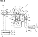
- FIG. 1 is a schematic configuration diagram of an engine 1 provided with an exhaust device 60 according to the first embodiment.
- the engine 1 shown in FIG. 1 is an in-line, four-cylinder internal combustion engine mounted on a vehicle, for example.
- the engine 1 includes a cylinder block 10, a cylinder head 20 fixed to an upper portion of the cylinder block 10.
- the cylinder block 10 is comprised of a cylinder portion 10A, and a crank case 10B formed in the lower portion of the cylinder portion 10A.
- cylinder portion 10A In the cylinder portion 10A, four cylinders 11 are formed. Within the cylinder 11, a piston 12 is disposed slidably. The piston 12 receives combustion pressure during air-fuel mixture combustion and reciprocates along the cylinder 11.
- the crank case 10B supports a single crank shaft 13 rotatably.
- Each piston 12 is connected to a connecting rod 14.
- the lower end of each connecting rod 14 is connected to the crank shaft 13. Reciprocating motion of the piston 12 is converted into rotary motion through the connecting rod 14 and crankshaft 13.
- the cylinder head 20 is attached to the upper surface of the cylinder block 10.
- the lower surface of the cylinder head 20, the side surface of the cylinder 11, and the crown surface of the piston 12 jointly forms a combustion chamber 15.
- the cylinder head 20 is formed with an intake ports 30 and an exhaust port 40 communicating with a combustion chamber 15.
- an intake ports 30 and an exhaust port 40 communicating with a combustion chamber 15.
- two intake ports 30 and two exhaust ports 40 are provided.
- the intake port 30 is provided with an intake valve 31.
- the intake valve 31 is driven by a swing cam of a variable valve mechanism 32 to open and close the intake port 30 in response to vertical movement of the piston 12.
- the variable valve mechanism 32 is capable of changing a valve characteristic such as a lift amount, operating angle, and the like of the intake valve 31.
- the exhaust port 40 is provided with an exhaust valve 41.
- the exhaust valve 41 is driven by a swing cam of the variable valve mechanism 42 to open and close the exhaust port 40 in response to vertical movement of the piston 12.
- the variable valve mechanism 42 is also capable of changing a valve characteristic such as a lift amount, operating angle, and the like of exhaust valve 41.
- An ignition plug 27 is installed in the cylinder head 20 between the intake port 30 and exhaust port 40.
- One spark plugs 27 is provided for each combustion chamber 15 of the engine 1. The spark plug 27 ignites the air-fuel mixture in the combustion chamber 15 at a predetermined timing.
- water jackets 16, 22 are provided, respectively.
- the water jacket 16 and 22 function as a passage for circulation of cooling water (cooling fluid) for cooling around the cylinder 11 and the combustion chamber 15.
- the engine 1 further includes an intake device 50 for guiding the intake air (fresh air) into the engine 1, an exhaust device 60 for guiding the exhaust gas from the engine 1 to the outside.
- the intake system 50 includes an intake pipe 21, an intake manifold 22, an air cleaner 23, an airflow meter 24, a throttle valve 25 of the electronically controlled type, and a fuel injection valve 26.
- the intake pipe 21 is a passage for flowing intake air.
- the intake manifold 22 communicates with the intake pipe 21 and the intake port 30.
- the intake manifold 22 distributes the intake air to each cylinder of the engine 1.
- the intake pipe 21 and the intake manifold 22 function as an intake passage for guiding the intake air to the engine 1.
- An air cleaner 23 is provided at the upstream end of the intake pipe 21.
- the air cleaner 23 is intended to remove foreign matter such as dust and dirt from the air taken in from the outside.
- An air flow meter 24 is installed in the intake pipe 21 downstream of the air cleaner 23.
- the air flow meter 24 detects the amount of intake air flowing through the intake pipe 21, and outputs a detection signal to the controller 80.
- the throttle valve 25 In the intake pipe 21 downstream of the air flow meter 24, the throttle valve 25 is provided.
- the throttle valve 25 adjusts the amount of intake air introduced into the combustion chamber 15 by changing the passage cross-sectional area of the intake pipe 21 continuously or stepwise.
- the throttle valve 25 is driven to be opened and closed by a throttle actuator 25A. Opening of the throttle valve 25 is detected by a throttle sensor 25B.
- a fuel injector 26 is provided for each cylinder of the engine 1.
- each branch pipe of the intake manifold 22 is mounted with a fuel injector 26.
- the fuel injection valve 26 is intended to inject into the intake manifold 22 the amount of fuel in accordance with the operating state of the engine at a predetermined timing.
- the fuel supplied to the fuel injection valve 26 is stored in a fuel tank (not shown).
- the exhaust system 60 of the engine 1 is an apparatus for purifying exhaust gas from the engine and deriving to the outside.
- the exhaust system 60 includes an exhaust pipe 61, an exhaust manifold 62, a manifold catalytic converter 63, an underfloor catalytic converter 64, and an exhaust heat recovery unit 70.
- the upstream end of the exhaust manifold 62 is connected to the cylinder head 20, while the downstream end of the exhaust manifold 62 is connected to the exhaust pipe 61.
- the exhaust manifold 62 is intended to collect exhaust from each of the exhaust ports 40 for guiding to the exhaust pipe 61.
- the exhaust manifold 62 and the exhaust pipe 61 serves as an exhaust passage for guiding exhaust gas from the engine 1 to the outside.
- a confluence or junction pipe 62A of the exhaust manifold 62 is provided with the manifold catalytic converter 63.
- the manifold catalytic converter 63 includes an exhaust gas purification unit 63A to purify the exhaust.
- the exhaust gas purification unit 63A is constructed as a grid-like carrier, i.e., as a cylindrical member having a plurality of through-holes or rectifying holes capable of passing exhaust gas.
- the exhaust gas purification unit 63A may be configured as a honeycomb structure having the through-hole shaped in a hexagonal cross-section.
- the cross-sectional shape of the through-hole of the exhaust gas purification unit 63A is not limited to square or hexagonal, and may be formed in other shapes, such as circular, triangular, etc.
- the exhaust gas purification unit 63A purifies harmful substances such as carbon monoxide, hydrocarbons and nitrogen oxides contained in the exhaust gas which pass through the through-holes by the three-way catalyst.
- the through-holes of the exhaust gas purification unit 63A also function to rectify the flow of exhaust gas in a fixed direction (passage extending direction).
- the manifold catalytic converter 63 is configured as a flow rectifier having an exhaust gas purification unit 63A (rectifying portion) to adjust the flow of exhaust.
- the junction pipe 62A on the upstream side of the exhaust gas purification unit 63A is formed as a radially expanding or diameter increasing portion 62B whose diameter increases toward the exhaust gas purification unit 63A.
- the junction pipe 62A on the downstream side of the exhaust gas purification unit 63A is formed as a radially contracting or diameter reducing portion 62C whose diameter is reduced toward the downstream from the exhaust purification unit 63A.
- the downstream end of the junction pipe 62A of the exhaust manifold 62 is connected to the exhaust pipe 61.
- the exhaust pipe 61 is a passage for guiding the exhaust gas that has passed through the exhaust manifold 62 to the outside.
- the exhaust pipe 61 is connected to the underfloor catalytic converter 64 and the exhaust heat recovery unit 70 disposed in this order from the upstream side.
- the underfloor catalytic converter 64 includes an exhaust gas purification portion 64A to purify the exhaust.
- the exhaust gas purification portion 64A is constructed as a grid-like carrier as shown in FIG. 2 , i.e., as a cylindrical member having a plurality of through-holes 64B capable of passing exhaust gas.
- the exhaust gas purification portion 64A may be configured as a honeycomb structure having the through-hole 64B shaped in a hexagonal cross-section. Note that the cross-sectional shape of the through-hole 64B is not limited to square or hexagonal, and may be formed in other shapes, such as circular, triangular, etc.
- the exhaust gas purification portion 64A purifies harmful substances such as carbon monoxide, hydrocarbons and nitrogen oxides contained in the exhaust gas which pass through the through-holes 64B by the three-way catalyst.
- the through-holes 64B of the exhaust gas purification portion 64A also function to rectify the flow of exhaust gas in a fixed direction (passage extending direction).
- the underfloor catalytic converter 64 is configured as a flow rectifier having an exhaust gas purification portion 64A (rectifying portion) to adjust the flow of exhaust.
- the exhaust heat recovery unit 70 is provided adjacent to and downstream of the underfloor catalytic converter 64.
- the exhaust heat recovery unit 70 is a device for recovering exhaust heat that has passed through the exhaust gas purifying portion 64A of the underfloor catalytic converter 64. Heat recovered by the exhaust heat recovery unit 70 is used for warming up of the engine 1 or air-conditioning.
- the exhaust gas discharged from the engine 1 to the exhaust system 60 is purified by the manifold catalytic converter 63 and the underfloor catalytic converter 64, and is guided to the outside through the exhaust pipe 61 after the heat has been recovered by the exhaust heat recovery unit 70.
- the engine 1 described above is controlled by the controller 80.
- the controller 80 is constituted by a microcomputer including a central processing unit (CPU), a read-only memory (ROM), a random access memory (RAM), and input and output interface (I/O interface).
- CPU central processing unit
- ROM read-only memory
- RAM random access memory
- I/O interface input and output interface
- the controller 80 receives detection signals from various sensors for detecting operating conditions of the engine such as a temperature sensor 81, an engine rotation speed sensor 82, an accelerator pedal sensor, etc., in addition to detection signals from the air flow meter 24 and the throttle sensor 25B.
- the temperature sensor 81 detects a temperature of cooling water flowing through the water jacket 16.
- the engine rotation speed sensor 82 detects the engine rotation speed based on the crank angle.
- the accelerator pedal sensor 83 detects a depression amount of the accelerator pedal.
- the controller 80 optimally controls a throttle opening, a fuel injection quantity, an ignition timing and the like, based on the detected operating conditions of the engine 1.
- FIG. 3 is a perspective view of the exhaust heat recovery unit 70
- FIG. 4 is a IV-IV cross-sectional view of the exhaust heat recovery unit 70 in FIG. 3 .
- the exhaust heat recovery unit 70 includes the exhaust heat recovery portion 71 for recovering exhaust heat, and the cooling unit 72 for cooling the exhaust heat recovery portion 71 via the cooling water.
- the cooling section 72 is formed in a cylindrical member with the exhaust heat recovery portion 71 arranged inside the cooling section 72.
- the inner diameter of the cooling part 72 is formed slightly larger than the outer diameter of the exhaust heat recovery portion 71.
- the exhaust heat recovery portion 71 is fitted to the inner peripheral surface of the cooling portion 72.
- the exhaust heat recovery portion 71 is formed of a material having a higher thermal conductivity, for example, silicon carbide (SiC) than the material forming the exhaust pipe 61 and exhaust manifold 62.
- the exhaust heat recovery portion 71 is a grid-like cylindrical member having a plurality of through-holes 71A in which the exhaust can pass.
- the through-hole 71A penetrates in the axial direction from one end face of the exhaust heat recovery portion 71 to the other end face.
- the exhaust heat recovery portion 71 may be configured as a honeycomb structure having the through-hole 71A shaped in a hexagonal cross-section. Note that the cross-sectional shape of the through-hole 71A is not limited to square or hexagonal, and may be formed in other shapes, such as circular, triangular, etc.
- the exhaust heat recovery portion 71 is heated by exhaust gas passing through the through-hole 71A.
- the temperature of the exhaust gas will be lower after passing through the exhaust heat recovery portion 71 compared to the temperature of the exhaust gas before the exhaust passage.
- the cooling unit 72 is provided in the exhaust pipe 61 in a state of accommodating the exhaust heat recovery portion 71.
- the inside of the cooling section 72 is configured as a part of the exhaust passage to flow exhaust.
- the cooling unit 72 is provided with an annular passage 72A formed along the outer circumference of the exhaust heat recovery portion 71, an inlet port 72B for introducing the cooling water into the annular passage 72A, and a discharge port 72C for discharging the cooling water from the annular passage 72A.
- the inlet port 72B and the outlet port 72C are arranged offset by 180 degrees in the circumferential direction of the exhaust heat recovery portion 71.
- the cooling water pumped by the water pump of the engine 1 flows into the annular passage 72A of the exhaust heat recovery unit 70 through the inlet port 72B.
- the cooling water flows through the annular passage 72A to cool the exhaust heat recovery portion 71 from the outer peripheral side.
- the cooling water passing through the annular passage 72A is heated by the exhaust heat recovery portion 71, and is subsequently discharged from the exhaust heat recovery unit 70 through the discharge port 72C.
- the discharged cooling water is fed to the water jackets 16 and 22 in the cylinder block 10 and the cylinder head 20 as well as to the heating device (not shown) for use to warm-up the engine 1 and air-conditioning of a passenger compartment.
- FIG. 5 is a cross-sectional view of the exhaust system 60 near the exhaust heat recovery unit 70.
- the exhaust heat recovery unit 70 and the underfloor catalytic converter 64 are provided in an exhaust pipe 61 which constitutes part of the exhaust passage.
- the exhaust heat recovery portion 71 of the exhaust heat recovery unit 70 and an exhaust gas purification portion 64A of the underfloor catalytic converter 64 are of a cylindrical member and are disposed coaxially to each other.
- the exhaust pipe 61 includes a diameter expanding or increasing portion 61A located on the upstream side of the exhaust purification portion 64A of the underfloor catalytic converter 64, a first diameter reducing portion 61B formed between the underfloor catalytic converter 64 and the exhaust gas recovery unit 70, and a second diameter reducing portion 61C located on the downstream side of the exhaust heat recovery unit 70.
- the diameter increasing portion 61A of the exhaust pipe 61 is tapered and configured such that the passage diameter increases gradually from the upstream side toward the exhaust gas purification portion 64A.
- the first diameter reducing portion 61B of the exhaust pipe 61 is a connecting passage (connecting portion) that connects the underfloor catalytic converter 64 and the exhaust heat recovery unit 70.
- the first diameter reducing portion 61B is tapered and is configured such that the passage diameter is gradually reduced in the direction from the underfloor catalytic converter 64 toward the exhaust heat recovery unit 70.
- the exhaust pipe 61 between the diameter increasing portion 61A and the first diameter reducing portion 61B is formed as a flat passage with a constant passage diameter, and the exhaust gas purification portion 64A is provided on the flat passage.
- the second diameter reducing portion 61C of the exhaust pipe 61 is a connecting passage that connects to the exhaust outlet of the exhaust heat recovery unit 70 (connection part).
- the second diameter reducing portion 61C are tapered, passage diameter from the exhaust heat recovery unit 70 toward the downstream is formed gradually so as to reduce.
- the exhaust heat recovery unit 70 is disposed between the first diameter reducing portion 61B and the second diameter reducing portion 61C.
- the outer diameter of the exhaust heat recovery portion 71 of the exhaust heat recovery unit 70 is configured to be smaller than the outer diameter of the exhaust gas purification portion 64A, and is configured to be larger than the inner diameter of t the exhaust pipe 61 on the downstream side of the second diameter reducing portion 61C.
- the inner diameter of the exhaust pipe 61 on the downstream side of the second diameter reducing portion 61 is configured to be the same as the inner diameter of the exhaust pipe 61 on the upstream side of the diameter increasing portion 61A.
- the outer diameter of the exhaust gas purification portion 64A is configured to be larger than the inner diameter of the exhaust pipe 61 on the upstream side of the diameter increasing portion 61A.
- the flow in front of the exhaust gas flowing into the exhaust gas purification portion 64A is relatively irregular.
- the exhaust gas flowing through upstream of the underfloor catalytic converter 64 is widened or expanded through the diameter increasing portion 61A and is introduced into the underfloor catalytic converter 64.
- the exhaust gas led to the underfloor catalytic converter 64 is rectified by passing through the through-hole 64B of the exhaust gas purification portion 64A, and a linear flow along the passage extending direction will be formed.
- the exhaust gas is guided to the exhaust heat recovery unit 70, after the exhaust gas purification portion 64A passes through the first diameter reducing portion 61B. Therefore, the exhaust heat recovery portion 71 of the exhaust heat recovery unit 70 receives rectified exhaust gas in a relatively uniform flow by the exhaust gas purification portion 64A.
- the exhaust gas flowing out from the through-holes 64B present near the outer periphery of the exhaust gas purification portion 64A is caused to be collected along the first diameter reducing portion 61B, the amount of exhaust gas flowing into the peripheral portion of the exhaust heat recovery portion 71 will be larger compared to the central portion.
- the outer peripheral portion of the exhaust heat recovery portion 71 is easily heated. As a result, it is possible to increase the temperature of the outer peripheral portion of the exhaust heat recovery portion 71.
- the cooling portion 72 of the exhaust heat recovery unit 70 includes a structure that removes heat from the outer peripheral side of the exhaust heat recovery portion 71. Therefore, by increasing the temperature of the outer peripheral portion of the exhaust heat recovery portion 71 as described above, it is possible to efficiently recover heat of the exhaust heat recovery portion 71 by the cooling unit 72.
- the exhaust gas that has passed through the exhaust heat recovery unit 70 is collected toward the center of the exhaust pipe 61 through a second diameter reducing portion 61C, and is discharged to the outside through the exhaust pipe 61.
- an exhaust pipe 61 that constitutes the exhaust passage includes a first diameter reducing portion 61 B which is gradually reduced in diameter toward the downstream between the underfloor catalytic converter 64 and the exhaust heat recovery unit 70, and a second diameter reducing portion 61C which is gradually reduced in diameter toward the downstream from the heat recovery unit 70. Since the exhaust gas rectified when passing through the exhaust gas purification portion 64A of the underfloor catalytic converter 64 is led to the exhaust heat recovery portion 71 of the exhaust heat recovery unit 70, the exhaust gas is likely to flow into the exhaust heat recovery portion 71 with ease. The exhaust gas flowing out from the through-holes 64B near the outer periphery of the exhaust gas purification portion 64A is collected along a first diameter reducing portion 61B.
- the temperature of the peripheral portion of the exhaust heat recovery portion 71 is further enhanced. Because the exhaust heat recovery unit 70 has a structure which extracts heat from the outer periphery of the exhaust heat recovery portion 71, by increasing the temperature of the outer peripheral portion of the exhaust heat recovery portion 71, it is possible to improve the exhaust heat recovery efficiency. Further, it is not necessary to provide a separate flow rectifier with the rectifying or straightening portion since the exhaust gas purification portion 64A of the underfloor catalytic converter 64 also functions as a rectifying portion. Therefore, it is possible to simplify the structure of the exhaust system 60.
- the exhaust pipe 61 is further provided with the diameter increasing portion 61A whose diameter increases gradually from the upstream side to the underfloor catalytic converter 64.
- the exhaust gas purification portion 64A of the underfloor catalytic converter 64 which adjusts the flow of exhaust is provided at a portion with a large inner diameter of passage between the diameter increasing portion 61A and the first diameter reducing portion 61B. Therefore, it is possible to place an exhaust gas purifying portion 64A of the large outer diameter. Therefore, it is possible to enhance the rectifying effect of the exhaust gas purification portion 64A.
- the exhaust gas purification portion 64A of the underfloor catalytic converter 64 is formed as a cylindrical member having a plurality of through-holes 64B.
- the exhaust heat recovery portion 71 of the exhaust heat recovery unit 70 is also formed as a cylindrical member having a plurality of through-holes 71A.
- the outer diameter of the exhaust heat recovery portion 71 is configured to be smaller than the outer diameter of the exhaust gas purification portion 64A, and configured to be larger than the inner diameter of the exhaust pipe 61 downstream of the second diameter reducing portion 61C.
- the exhaust gas purification portion 64A of the underfloor catalytic converter 64 is preferably configured as a honeycomb structure with the through-hole 64B shaped in a hexagonal cross-section. With such a configuration, it is possible to densely the arrangement of the through-holes 64B in the exhaust gas purification portion 64A. Thus, the rectifying function is improved. Therefore, it is possible to produce a more uniform discharge in the exhaust heat recovery unit 70.
- the exhaust heat recovery portion 71 of the exhaust heat recovery unit 70 also is preferably configured as a honeycomb structure with the through-hole 71A shaped in a hexagonal cross-section. With this configuration, it is possible to densely arrange the through-holes 71 A in the exhaust heat recovery portion 71. Thus, the exhaust heat recovery function is improved. This configuration makes it possible to further improve the exhaust heat recovery efficiency at the exhaust heat recovery unit 70.
- the opening area (passage diameter) of the through-hole 64B of the exhaust gas purification portion 64A is preferably configured to be smaller than that of the through-hole 71A of the heat recovery unit 71.
- the number of the through-holes 64B is preferably configured to be larger than that of the through-holes 71A.
- the exhaust system 60 of the engine 1 according to the second embodiment is different from the exhaust system of the first embodiment in that the exhaust heat recovery unit 70 is located immediately after the manifold catalytic converter 63.
- the same reference numerals as the first embodiment are used for those configurations and the like that are equivalent to the first embodiment without redundant descriptions.
- the exhaust pipe 61 is connected to the downstream end of the exhaust manifold 62, and the manifold catalytic converter 63 is provided in the exhaust pipe 61.
- the configuration of the manifold catalytic converter 63 according to the present embodiment is the same as the manifold catalytic converter 63 according to the first embodiment.
- the inner diameter of the exhaust pipe 61 in which the manifold catalytic converter 63 is provided is configured to be substantially equal to the inner diameter of the junction pipe formed downstream of the exhaust manifold 62.
- the exhaust heat recovery unit 70 is installed, rather than downstream of the underfloor catalytic converter 64, downstream of the exhaust pipe 61 of the manifold catalytic converter 63.
- the exhaust pipe 61 includes a first diameter reducing portion 61B which is formed between the manifold catalytic converter 63 and the exhaust heat recovery unit 70, and a second diameter reducing portion 61C formed on the downstream side of the exhaust heat recovery unit 70.
- the first diameter reducing portion 61B of the exhaust pipe 61 is a connecting passage (connecting portion) that connects the manifold catalytic converter 63 and the exhaust heat recovery unit 70.
- the first diameter reducing portion 61B is tapered, and is configured such that the passage diameter is gradually reduced in the direction from the manifold catalytic converter 63 to the exhaust heat recovery unit 70.
- the second diameter reducing portion 61C of the exhaust pipe 61 is a connecting passage (connection portion) that is connected to the exhaust outlet of the exhaust heat recovery unit 70.
- the second diameter reducing portion 61C is tapered, and is configured such that the passage diameter is gradually reduced from the exhaust heat recovery unit 70 toward the downstream. Note that on the downstream side of the exhaust pipe 61 of the second diameter reducing portion 61C, an underfloor catalytic converter 64 is provided (not shown in FIG 6 )..
- the outer diameter of the exhaust heat recovery portion 71 of the exhaust heat recovery unit 70 is configured to be smaller than the outer diameter of the exhaust gas purification unit 63A, and larger than the inner diameter of the exhaust pipe 61 downstream of the second diameter reducing portion 61C.
- the exhaust gas is rectified by passing through the through-holes 63B of the exhaust gas purification unit 63A of the manifold catalytic converter 63 and introduced in the exhaust heat recovery portion 71 of the exhaust heat recovery unit 70. Therefore, the exhaust gas is likely to flow into the exhaust heat recovery portion 71 with ease. Since the exhaust gas flowing out from the through-holes 63B present near the outer periphery of the exhaust gas purification unit 63A is caused to be collected along a first diameter reducing portion 61B, the temperature of the peripheral portion of the exhaust heat recovery portion 71 is further enhanced. Because the exhaust heat recovery unit 70 includes a structure that removes heat from the outer peripheral side of the exhaust heat recovery portion 71, by increasing the temperature of the outer peripheral portion of the exhaust heat recovery portion 71, it is possible to improve the exhaust heat recovery efficiency.
- the exhaust gas purification unit 63A of a manifold catalytic converter 63 is preferably configured as a honeycomb structure with the through-hole 63B shaped in hexagonal cross-section. With such a configuration, it is possible to densely arrange the through-holes 63B in the exhaust gas purification unit 63A. Thus, the rectifying function is improved.
- the exhaust heat recovery portion 71 of the exhaust heat recovery unit 70 also is preferably configured as a honeycomb structure with the through-hole 71A shaped in a hexagonal cross-section. With this configuration, it is possible to densely arrange the through-holes 71A in the exhaust heat recovery portion 71. Thus, the exhaust heat recovery function is improved.
- the opening area (passage diameter) of the through-hole 63B of the exhaust gas purification unit 63A is preferably set smaller than the through-hole 71A of the heat recovery unit 71, and the number of the through-holes 63B is preferably set larger than the through-hole 71A.
- the exhaust gas purification units 63A, 64A of the catalytic converter are configures as a rectifying portion.
- a rectifying portion having only exhaust rectifying function without exhaust purification function may be disposed.
Landscapes
- Engineering & Computer Science (AREA)
- Chemical & Material Sciences (AREA)
- Combustion & Propulsion (AREA)
- Mechanical Engineering (AREA)
- General Engineering & Computer Science (AREA)
- Chemical Kinetics & Catalysis (AREA)
- Health & Medical Sciences (AREA)
- Toxicology (AREA)
- Materials Engineering (AREA)
- Exhaust Gas After Treatment (AREA)
- Exhaust Gas Treatment By Means Of Catalyst (AREA)
Abstract
Description
- The present invention relates to an exhaust system for an engine.
- In the
JP2011-169514A - In the exhaust system of the engine described above, the upstream side of the exhaust passage of the exhaust heat recovery unit is configured to increase in diameter toward the exhaust heat recovery unit. In such a configuration, the exhaust gas that has passed through the catalyst does not uniformly flow into the exhaust heat recovery unit, but rather flows unevenly and concentrated in a central portion of the exhaust heat recovery unit. As a result, it is not possible to utilize the entire exhaust heat recovery unit so that a problem arises in that the recovery efficiency of the exhaust heat by the exhaust heat recovery unit deteriorates.
- The present invention has been made in view of the above problem and aims to provide an exhaust system for an engine capable of enhancing the exhaust heat recovery efficiency by the exhaust heat recovery unit.
- According to one aspect of the present invention, an exhaust system for an engine includes an exhaust passage for flowing exhaust gas emitted from the engine, a flow rectifier having a rectifying portion for rectifying the flow of exhaust gas in the exhaust passage, and an exhaust heat recovery unit disposed in the exhaust passage downstream of the flow rectifier and provided with an exhaust heat recovery portion for recovering exhaust heat and a cooling portion for cooling the exhaust heat recovery portion from the outer peripheral side thereof through cooling fluid. The exhaust passage includes a first radially contracting or diameter reducing portion which is gradually reduced in diameter toward the exhaust heat recovery unit from the flow rectifier, and a second radially contracting, or diameter reducing portion which is gradually reduced in diameter toward the downstream of the exhaust heat recovery unit.
-
-
Fig. 1 is a schematic configuration diagram of an engine provided with an exhaust device according to a first embodiment; -
FIG. 2 is a front view of an exhaust gas purification unit of an underfloor catalytic converter; -
FIG. 3 is a perspective view of an exhaust heat recovery unit; -
FIG 4 is a IV-IV cross-sectional view of the exhaust heat recovery unit shown inFIG. 3 ; -
FIG 5 is a cross-sectional view of the exhaust heat recovery unit near the exhaust system; and -
FIG 6 is a sectional view showing the exhaust system of the engine according to a second embodiment. - Hereinafter, with reference to the accompanying drawings, embodiments of the present invention will be described.
-
FIG. 1 is a schematic configuration diagram of an engine 1 provided with anexhaust device 60 according to the first embodiment. - The engine 1 shown in
FIG. 1 is an in-line, four-cylinder internal combustion engine mounted on a vehicle, for example. The engine 1 includes acylinder block 10, acylinder head 20 fixed to an upper portion of thecylinder block 10. - The
cylinder block 10 is comprised of acylinder portion 10A, and acrank case 10B formed in the lower portion of thecylinder portion 10A. - In the
cylinder portion 10A, fourcylinders 11 are formed. Within thecylinder 11, apiston 12 is disposed slidably. Thepiston 12 receives combustion pressure during air-fuel mixture combustion and reciprocates along thecylinder 11. - The
crank case 10B supports asingle crank shaft 13 rotatably. Eachpiston 12 is connected to a connectingrod 14. The lower end of each connectingrod 14 is connected to thecrank shaft 13. Reciprocating motion of thepiston 12 is converted into rotary motion through the connectingrod 14 andcrankshaft 13. - The
cylinder head 20 is attached to the upper surface of thecylinder block 10. The lower surface of thecylinder head 20, the side surface of thecylinder 11, and the crown surface of thepiston 12 jointly forms acombustion chamber 15. - Further, the
cylinder head 20 is formed with anintake ports 30 and anexhaust port 40 communicating with acombustion chamber 15. For onecombustion chamber 15, twointake ports 30 and twoexhaust ports 40 are provided. - The
intake port 30 is provided with anintake valve 31. Theintake valve 31 is driven by a swing cam of avariable valve mechanism 32 to open and close theintake port 30 in response to vertical movement of thepiston 12. Thevariable valve mechanism 32 is capable of changing a valve characteristic such as a lift amount, operating angle, and the like of theintake valve 31. Also, theexhaust port 40 is provided with anexhaust valve 41. Theexhaust valve 41 is driven by a swing cam of thevariable valve mechanism 42 to open and close theexhaust port 40 in response to vertical movement of thepiston 12. Thevariable valve mechanism 42 is also capable of changing a valve characteristic such as a lift amount, operating angle, and the like ofexhaust valve 41. - An
ignition plug 27 is installed in thecylinder head 20 between theintake port 30 andexhaust port 40. Onespark plugs 27 is provided for eachcombustion chamber 15 of the engine 1. Thespark plug 27 ignites the air-fuel mixture in thecombustion chamber 15 at a predetermined timing. - In the
cylinder portion 10A of the cylinder block and in thecylinder head 20,water jackets water jacket cylinder 11 and thecombustion chamber 15. - The engine 1 further includes an
intake device 50 for guiding the intake air (fresh air) into the engine 1, anexhaust device 60 for guiding the exhaust gas from the engine 1 to the outside. - The
intake system 50 includes anintake pipe 21, anintake manifold 22, anair cleaner 23, anairflow meter 24, athrottle valve 25 of the electronically controlled type, and afuel injection valve 26. - The
intake pipe 21 is a passage for flowing intake air. Theintake manifold 22 communicates with theintake pipe 21 and theintake port 30. Theintake manifold 22 distributes the intake air to each cylinder of the engine 1. Theintake pipe 21 and theintake manifold 22 function as an intake passage for guiding the intake air to the engine 1. - An
air cleaner 23 is provided at the upstream end of theintake pipe 21. Theair cleaner 23 is intended to remove foreign matter such as dust and dirt from the air taken in from the outside. - An
air flow meter 24 is installed in theintake pipe 21 downstream of theair cleaner 23. Theair flow meter 24 detects the amount of intake air flowing through theintake pipe 21, and outputs a detection signal to thecontroller 80. - In the
intake pipe 21 downstream of theair flow meter 24, thethrottle valve 25 is provided. Thethrottle valve 25 adjusts the amount of intake air introduced into thecombustion chamber 15 by changing the passage cross-sectional area of theintake pipe 21 continuously or stepwise. Thethrottle valve 25 is driven to be opened and closed by athrottle actuator 25A. Opening of thethrottle valve 25 is detected by athrottle sensor 25B. - In the
intake manifold 22, afuel injector 26 is provided for each cylinder of the engine 1. In other words, each branch pipe of theintake manifold 22 is mounted with afuel injector 26. Thefuel injection valve 26 is intended to inject into theintake manifold 22 the amount of fuel in accordance with the operating state of the engine at a predetermined timing. The fuel supplied to thefuel injection valve 26 is stored in a fuel tank (not shown). - The
exhaust system 60 of the engine 1 is an apparatus for purifying exhaust gas from the engine and deriving to the outside. Theexhaust system 60 includes anexhaust pipe 61, anexhaust manifold 62, a manifoldcatalytic converter 63, an underfloorcatalytic converter 64, and an exhaustheat recovery unit 70. - The upstream end of the
exhaust manifold 62 is connected to thecylinder head 20, while the downstream end of theexhaust manifold 62 is connected to theexhaust pipe 61. Theexhaust manifold 62 is intended to collect exhaust from each of theexhaust ports 40 for guiding to theexhaust pipe 61. Theexhaust manifold 62 and theexhaust pipe 61 serves as an exhaust passage for guiding exhaust gas from the engine 1 to the outside. - A confluence or
junction pipe 62A of theexhaust manifold 62 is provided with the manifoldcatalytic converter 63. The manifoldcatalytic converter 63 includes an exhaustgas purification unit 63A to purify the exhaust. The exhaustgas purification unit 63A is constructed as a grid-like carrier, i.e., as a cylindrical member having a plurality of through-holes or rectifying holes capable of passing exhaust gas. The exhaustgas purification unit 63A may be configured as a honeycomb structure having the through-hole shaped in a hexagonal cross-section. The cross-sectional shape of the through-hole of the exhaustgas purification unit 63A is not limited to square or hexagonal, and may be formed in other shapes, such as circular, triangular, etc. - On the surface of the exhaust
gas purification unit 63A, a three-way catalyst for purifying exhaust is supported. The exhaustgas purification unit 63A purifies harmful substances such as carbon monoxide, hydrocarbons and nitrogen oxides contained in the exhaust gas which pass through the through-holes by the three-way catalyst. The through-holes of the exhaustgas purification unit 63A also function to rectify the flow of exhaust gas in a fixed direction (passage extending direction). Thus, the manifoldcatalytic converter 63 is configured as a flow rectifier having an exhaustgas purification unit 63A (rectifying portion) to adjust the flow of exhaust. - The
junction pipe 62A on the upstream side of the exhaustgas purification unit 63A is formed as a radially expanding ordiameter increasing portion 62B whose diameter increases toward the exhaustgas purification unit 63A. Thejunction pipe 62A on the downstream side of the exhaustgas purification unit 63A is formed as a radially contracting ordiameter reducing portion 62C whose diameter is reduced toward the downstream from theexhaust purification unit 63A. By thus constituting thejunction pipe 62A, an increase in the exhaust resistance can be suppressed even with the exhaustgas purification unit 63A arranged in thejunction pipe 62A. - The downstream end of the
junction pipe 62A of theexhaust manifold 62 is connected to theexhaust pipe 61. Theexhaust pipe 61 is a passage for guiding the exhaust gas that has passed through theexhaust manifold 62 to the outside. Theexhaust pipe 61 is connected to the underfloorcatalytic converter 64 and the exhaustheat recovery unit 70 disposed in this order from the upstream side. - The underfloor
catalytic converter 64 includes an exhaustgas purification portion 64A to purify the exhaust. The exhaustgas purification portion 64A is constructed as a grid-like carrier as shown inFIG. 2 , i.e., as a cylindrical member having a plurality of through-holes 64B capable of passing exhaust gas. The exhaustgas purification portion 64A may be configured as a honeycomb structure having the through-hole 64B shaped in a hexagonal cross-section. Note that the cross-sectional shape of the through-hole 64B is not limited to square or hexagonal, and may be formed in other shapes, such as circular, triangular, etc. - On the surface of the exhaust
gas purification portion 64A, a three-way catalyst for purifying exhaust is supported. The exhaustgas purification portion 64A purifies harmful substances such as carbon monoxide, hydrocarbons and nitrogen oxides contained in the exhaust gas which pass through the through-holes 64B by the three-way catalyst. The through-holes 64B of the exhaustgas purification portion 64A also function to rectify the flow of exhaust gas in a fixed direction (passage extending direction). Thus, the underfloorcatalytic converter 64 is configured as a flow rectifier having an exhaustgas purification portion 64A (rectifying portion) to adjust the flow of exhaust. - As shown in
FIG. 1 , the exhaustheat recovery unit 70 is provided adjacent to and downstream of the underfloorcatalytic converter 64. The exhaustheat recovery unit 70 is a device for recovering exhaust heat that has passed through the exhaustgas purifying portion 64A of the underfloorcatalytic converter 64. Heat recovered by the exhaustheat recovery unit 70 is used for warming up of the engine 1 or air-conditioning. - The exhaust gas discharged from the engine 1 to the
exhaust system 60 is purified by the manifoldcatalytic converter 63 and the underfloorcatalytic converter 64, and is guided to the outside through theexhaust pipe 61 after the heat has been recovered by the exhaustheat recovery unit 70. - The engine 1 described above is controlled by the
controller 80. Thecontroller 80 is constituted by a microcomputer including a central processing unit (CPU), a read-only memory (ROM), a random access memory (RAM), and input and output interface (I/O interface). - The
controller 80 receives detection signals from various sensors for detecting operating conditions of the engine such as atemperature sensor 81, an enginerotation speed sensor 82, an accelerator pedal sensor, etc., in addition to detection signals from theair flow meter 24 and thethrottle sensor 25B. Thetemperature sensor 81 detects a temperature of cooling water flowing through thewater jacket 16. The enginerotation speed sensor 82 detects the engine rotation speed based on the crank angle. Theaccelerator pedal sensor 83 detects a depression amount of the accelerator pedal. - The
controller 80 optimally controls a throttle opening, a fuel injection quantity, an ignition timing and the like, based on the detected operating conditions of the engine 1. - Now, with reference to
FIGS. 3 and4 , description will be given of a configuration of the exhaustheat recovery unit 70.Figure 3 is a perspective view of the exhaustheat recovery unit 70,FIG. 4 is a IV-IV cross-sectional view of the exhaustheat recovery unit 70 inFIG. 3 . - As shown in
FIGS. 3 and4 , the exhaustheat recovery unit 70 includes the exhaustheat recovery portion 71 for recovering exhaust heat, and thecooling unit 72 for cooling the exhaustheat recovery portion 71 via the cooling water. - The
cooling section 72 is formed in a cylindrical member with the exhaustheat recovery portion 71 arranged inside thecooling section 72. The inner diameter of the coolingpart 72 is formed slightly larger than the outer diameter of the exhaustheat recovery portion 71. The exhaustheat recovery portion 71 is fitted to the inner peripheral surface of the coolingportion 72. - The exhaust
heat recovery portion 71 is formed of a material having a higher thermal conductivity, for example, silicon carbide (SiC) than the material forming theexhaust pipe 61 andexhaust manifold 62. The exhaustheat recovery portion 71 is a grid-like cylindrical member having a plurality of through-holes 71A in which the exhaust can pass. The through-hole 71A penetrates in the axial direction from one end face of the exhaustheat recovery portion 71 to the other end face. The exhaustheat recovery portion 71 may be configured as a honeycomb structure having the through-hole 71A shaped in a hexagonal cross-section. Note that the cross-sectional shape of the through-hole 71A is not limited to square or hexagonal, and may be formed in other shapes, such as circular, triangular, etc. - The exhaust
heat recovery portion 71 is heated by exhaust gas passing through the through-hole 71A. The temperature of the exhaust gas will be lower after passing through the exhaustheat recovery portion 71 compared to the temperature of the exhaust gas before the exhaust passage. - The cooling
unit 72 is provided in theexhaust pipe 61 in a state of accommodating the exhaustheat recovery portion 71. The inside of thecooling section 72 is configured as a part of the exhaust passage to flow exhaust. - The cooling
unit 72 is provided with anannular passage 72A formed along the outer circumference of the exhaustheat recovery portion 71, aninlet port 72B for introducing the cooling water into theannular passage 72A, and a discharge port 72C for discharging the cooling water from theannular passage 72A. Theinlet port 72B and the outlet port 72C are arranged offset by 180 degrees in the circumferential direction of the exhaustheat recovery portion 71. - The cooling water pumped by the water pump of the engine 1 (not shown) flows into the
annular passage 72A of the exhaustheat recovery unit 70 through theinlet port 72B. The cooling water flows through theannular passage 72A to cool the exhaustheat recovery portion 71 from the outer peripheral side. The cooling water passing through theannular passage 72A is heated by the exhaustheat recovery portion 71, and is subsequently discharged from the exhaustheat recovery unit 70 through the discharge port 72C. The discharged cooling water is fed to thewater jackets cylinder block 10 and thecylinder head 20 as well as to the heating device (not shown) for use to warm-up the engine 1 and air-conditioning of a passenger compartment. - Now, with reference to
FIG. 5 , a description will be given of a structure of the exhaust passage in the vicinity of the exhaustheat recovery unit 70.FIG. 5 is a cross-sectional view of theexhaust system 60 near the exhaustheat recovery unit 70. - As shown in
FIG. 5 , the exhaustheat recovery unit 70 and the underfloorcatalytic converter 64 are provided in anexhaust pipe 61 which constitutes part of the exhaust passage. The exhaustheat recovery portion 71 of the exhaustheat recovery unit 70 and an exhaustgas purification portion 64A of the underfloorcatalytic converter 64 are of a cylindrical member and are disposed coaxially to each other. - The
exhaust pipe 61 includes a diameter expanding or increasingportion 61A located on the upstream side of theexhaust purification portion 64A of the underfloorcatalytic converter 64, a firstdiameter reducing portion 61B formed between the underfloorcatalytic converter 64 and the exhaustgas recovery unit 70, and a seconddiameter reducing portion 61C located on the downstream side of the exhaustheat recovery unit 70. - The
diameter increasing portion 61A of theexhaust pipe 61 is tapered and configured such that the passage diameter increases gradually from the upstream side toward the exhaustgas purification portion 64A. - The first
diameter reducing portion 61B of theexhaust pipe 61 is a connecting passage (connecting portion) that connects the underfloorcatalytic converter 64 and the exhaustheat recovery unit 70. The firstdiameter reducing portion 61B is tapered and is configured such that the passage diameter is gradually reduced in the direction from the underfloorcatalytic converter 64 toward the exhaustheat recovery unit 70. Note that theexhaust pipe 61 between thediameter increasing portion 61A and the firstdiameter reducing portion 61B is formed as a flat passage with a constant passage diameter, and the exhaustgas purification portion 64A is provided on the flat passage. - The second
diameter reducing portion 61C of theexhaust pipe 61 is a connecting passage that connects to the exhaust outlet of the exhaust heat recovery unit 70 (connection part). The seconddiameter reducing portion 61C are tapered, passage diameter from the exhaustheat recovery unit 70 toward the downstream is formed gradually so as to reduce. - The exhaust
heat recovery unit 70 is disposed between the firstdiameter reducing portion 61B and the seconddiameter reducing portion 61C. The outer diameter of the exhaustheat recovery portion 71 of the exhaustheat recovery unit 70 is configured to be smaller than the outer diameter of the exhaustgas purification portion 64A, and is configured to be larger than the inner diameter of t theexhaust pipe 61 on the downstream side of the seconddiameter reducing portion 61C. Note that the inner diameter of theexhaust pipe 61 on the downstream side of the seconddiameter reducing portion 61 is configured to be the same as the inner diameter of theexhaust pipe 61 on the upstream side of thediameter increasing portion 61A. Also, the outer diameter of the exhaustgas purification portion 64A is configured to be larger than the inner diameter of theexhaust pipe 61 on the upstream side of thediameter increasing portion 61A. - As shown by an arrow in
FIG. 5 , the flow in front of the exhaust gas flowing into the exhaustgas purification portion 64A is relatively irregular. The exhaust gas flowing through upstream of the underfloorcatalytic converter 64 is widened or expanded through thediameter increasing portion 61A and is introduced into the underfloorcatalytic converter 64. The exhaust gas led to the underfloorcatalytic converter 64 is rectified by passing through the through-hole 64B of the exhaustgas purification portion 64A, and a linear flow along the passage extending direction will be formed. - The exhaust gas is guided to the exhaust
heat recovery unit 70, after the exhaustgas purification portion 64A passes through the firstdiameter reducing portion 61B. Therefore, the exhaustheat recovery portion 71 of the exhaustheat recovery unit 70 receives rectified exhaust gas in a relatively uniform flow by the exhaustgas purification portion 64A. However, since the exhaust gas flowing out from the through-holes 64B present near the outer periphery of the exhaustgas purification portion 64A is caused to be collected along the firstdiameter reducing portion 61B, the amount of exhaust gas flowing into the peripheral portion of the exhaustheat recovery portion 71 will be larger compared to the central portion. Thus, by increasing the amount of exhaust gas flowing into the peripheral portion of the exhaustheat recovery portion 71, the outer peripheral portion of the exhaustheat recovery portion 71 is easily heated. As a result, it is possible to increase the temperature of the outer peripheral portion of the exhaustheat recovery portion 71. - The cooling
portion 72 of the exhaustheat recovery unit 70 includes a structure that removes heat from the outer peripheral side of the exhaustheat recovery portion 71. Therefore, by increasing the temperature of the outer peripheral portion of the exhaustheat recovery portion 71 as described above, it is possible to efficiently recover heat of the exhaustheat recovery portion 71 by the coolingunit 72. - The exhaust gas that has passed through the exhaust
heat recovery unit 70 is collected toward the center of theexhaust pipe 61 through a seconddiameter reducing portion 61C, and is discharged to the outside through theexhaust pipe 61. - According to the
exhaust system 60 of the engine 1 in the first embodiment described above, it is possible to obtain the following effects. - In the
exhaust system 60 of the engine 1, anexhaust pipe 61 that constitutes the exhaust passage includes a firstdiameter reducing portion 61 B which is gradually reduced in diameter toward the downstream between the underfloorcatalytic converter 64 and the exhaustheat recovery unit 70, and a seconddiameter reducing portion 61C which is gradually reduced in diameter toward the downstream from theheat recovery unit 70. Since the exhaust gas rectified when passing through the exhaustgas purification portion 64A of the underfloorcatalytic converter 64 is led to the exhaustheat recovery portion 71 of the exhaustheat recovery unit 70, the exhaust gas is likely to flow into the exhaustheat recovery portion 71 with ease. The exhaust gas flowing out from the through-holes 64B near the outer periphery of the exhaustgas purification portion 64A is collected along a firstdiameter reducing portion 61B. Thus, the temperature of the peripheral portion of the exhaustheat recovery portion 71 is further enhanced. Because the exhaustheat recovery unit 70 has a structure which extracts heat from the outer periphery of the exhaustheat recovery portion 71, by increasing the temperature of the outer peripheral portion of the exhaustheat recovery portion 71, it is possible to improve the exhaust heat recovery efficiency. Further, it is not necessary to provide a separate flow rectifier with the rectifying or straightening portion since the exhaustgas purification portion 64A of the underfloorcatalytic converter 64 also functions as a rectifying portion. Therefore, it is possible to simplify the structure of theexhaust system 60. - The
exhaust pipe 61 is further provided with thediameter increasing portion 61A whose diameter increases gradually from the upstream side to the underfloorcatalytic converter 64. The exhaustgas purification portion 64A of the underfloorcatalytic converter 64 which adjusts the flow of exhaust is provided at a portion with a large inner diameter of passage between thediameter increasing portion 61A and the firstdiameter reducing portion 61B. Therefore, it is possible to place an exhaustgas purifying portion 64A of the large outer diameter. Therefore, it is possible to enhance the rectifying effect of the exhaustgas purification portion 64A. - The exhaust
gas purification portion 64A of the underfloorcatalytic converter 64 is formed as a cylindrical member having a plurality of through-holes 64B. The exhaustheat recovery portion 71 of the exhaustheat recovery unit 70 is also formed as a cylindrical member having a plurality of through-holes 71A. In addition, the outer diameter of the exhaustheat recovery portion 71 is configured to be smaller than the outer diameter of the exhaustgas purification portion 64A, and configured to be larger than the inner diameter of theexhaust pipe 61 downstream of the seconddiameter reducing portion 61C. With this configuration, it is possible to supply a relatively uniform exhaust gas to the entire entrance surface of the exhaustheat recovery portion 71. As a result, it is possible to improve the exhaust heat recovery efficiency by the exhaustheat recovery unit 70. - Note that, in the
exhaust system 60 of the engine 1, the exhaustgas purification portion 64A of the underfloorcatalytic converter 64 is preferably configured as a honeycomb structure with the through-hole 64B shaped in a hexagonal cross-section. With such a configuration, it is possible to densely the arrangement of the through-holes 64B in the exhaustgas purification portion 64A. Thus, the rectifying function is improved. Therefore, it is possible to produce a more uniform discharge in the exhaustheat recovery unit 70. - Moreover, the exhaust
heat recovery portion 71 of the exhaustheat recovery unit 70 also is preferably configured as a honeycomb structure with the through-hole 71A shaped in a hexagonal cross-section. With this configuration, it is possible to densely arrange the through-holes 71 A in the exhaustheat recovery portion 71. Thus, the exhaust heat recovery function is improved. This configuration makes it possible to further improve the exhaust heat recovery efficiency at the exhaustheat recovery unit 70. - Furthermore, the opening area (passage diameter) of the through-
hole 64B of the exhaustgas purification portion 64A is preferably configured to be smaller than that of the through-hole 71A of theheat recovery unit 71. In addition, the number of the through-holes 64B is preferably configured to be larger than that of the through-holes 71A. Thus, by setting the mesh or the rectifying hole of the exhaustgas purification portion 64A finer than the mesh of the exhaustheat recovery unit 71, it is possible to enhance the rectifying effect of the exhaustgas purification portion 64A. Thus, the exhaust passing through the exhaustgas purification portion 64A will be easily flown into the exhaustheat recovery portion 71. Therefore, it is possible to improve the exhaust heat recovery efficiency by the exhaustheat recovery unit 70. - With reference to
FIG. 6 , a description is made of theexhaust system 60 of the engine 1 according to the second embodiment according to the present invention. - The
exhaust system 60 of the engine 1 according to the second embodiment is different from the exhaust system of the first embodiment in that the exhaustheat recovery unit 70 is located immediately after the manifoldcatalytic converter 63. In the following, the same reference numerals as the first embodiment are used for those configurations and the like that are equivalent to the first embodiment without redundant descriptions. - As shown in
FIG. 6 , theexhaust pipe 61 is connected to the downstream end of theexhaust manifold 62, and the manifoldcatalytic converter 63 is provided in theexhaust pipe 61. The configuration of the manifoldcatalytic converter 63 according to the present embodiment is the same as the manifoldcatalytic converter 63 according to the first embodiment. The inner diameter of theexhaust pipe 61 in which the manifoldcatalytic converter 63 is provided is configured to be substantially equal to the inner diameter of the junction pipe formed downstream of theexhaust manifold 62. - In the present embodiment, the exhaust
heat recovery unit 70 is installed, rather than downstream of the underfloorcatalytic converter 64, downstream of theexhaust pipe 61 of the manifoldcatalytic converter 63. - The
exhaust pipe 61 includes a firstdiameter reducing portion 61B which is formed between the manifoldcatalytic converter 63 and the exhaustheat recovery unit 70, and a seconddiameter reducing portion 61C formed on the downstream side of the exhaustheat recovery unit 70. - The first
diameter reducing portion 61B of theexhaust pipe 61 is a connecting passage (connecting portion) that connects the manifoldcatalytic converter 63 and the exhaustheat recovery unit 70. The firstdiameter reducing portion 61B is tapered, and is configured such that the passage diameter is gradually reduced in the direction from the manifoldcatalytic converter 63 to the exhaustheat recovery unit 70. - The second
diameter reducing portion 61C of theexhaust pipe 61 is a connecting passage (connection portion) that is connected to the exhaust outlet of the exhaustheat recovery unit 70. The seconddiameter reducing portion 61C is tapered, and is configured such that the passage diameter is gradually reduced from the exhaustheat recovery unit 70 toward the downstream. Note that on the downstream side of theexhaust pipe 61 of the seconddiameter reducing portion 61C, an underfloorcatalytic converter 64 is provided (not shown inFIG 6 ).. - The outer diameter of the exhaust
heat recovery portion 71 of the exhaustheat recovery unit 70 is configured to be smaller than the outer diameter of the exhaustgas purification unit 63A, and larger than the inner diameter of theexhaust pipe 61 downstream of the seconddiameter reducing portion 61C. - In the
exhaust system 60 of the engine 1 according to the second embodiment, the exhaust gas is rectified by passing through the through-holes 63B of the exhaustgas purification unit 63A of the manifoldcatalytic converter 63 and introduced in the exhaustheat recovery portion 71 of the exhaustheat recovery unit 70. Therefore, the exhaust gas is likely to flow into the exhaustheat recovery portion 71 with ease. Since the exhaust gas flowing out from the through-holes 63B present near the outer periphery of the exhaustgas purification unit 63A is caused to be collected along a firstdiameter reducing portion 61B, the temperature of the peripheral portion of the exhaustheat recovery portion 71 is further enhanced. Because the exhaustheat recovery unit 70 includes a structure that removes heat from the outer peripheral side of the exhaustheat recovery portion 71, by increasing the temperature of the outer peripheral portion of the exhaustheat recovery portion 71, it is possible to improve the exhaust heat recovery efficiency. - Note that, in the
exhaust system 60 of the engine 1, the exhaustgas purification unit 63A of a manifoldcatalytic converter 63 is preferably configured as a honeycomb structure with the through-hole 63B shaped in hexagonal cross-section. With such a configuration, it is possible to densely arrange the through-holes 63B in the exhaustgas purification unit 63A. Thus, the rectifying function is improved. - Moreover, the exhaust
heat recovery portion 71 of the exhaustheat recovery unit 70 also is preferably configured as a honeycomb structure with the through-hole 71A shaped in a hexagonal cross-section. With this configuration, it is possible to densely arrange the through-holes 71A in the exhaustheat recovery portion 71. Thus, the exhaust heat recovery function is improved. - Furthermore, the opening area (passage diameter) of the through-
hole 63B of the exhaustgas purification unit 63A is preferably set smaller than the through-hole 71A of theheat recovery unit 71, and the number of the through-holes 63B is preferably set larger than the through-hole 71A. Thus, by setting the mesh of the exhaustgas purification portion 63A finer that of the exhaustheat recovery unit 71, it is possible to enhance the rectifying effect of the exhaustgas purification portion 63A. - The present invention is not limited to the above embodiments. It is obvious that various modifications can be made within the scope of the technical spirit thereof.
- In the above embodiment, the exhaust
gas purification units exhaust device 60, on the upstream side of the exhaustheat recovery unit 70, a rectifying portion having only exhaust rectifying function without exhaust purification function may be disposed. - As described above, a description is given of the embodiments according to the present invention. However, the above embodiments merely show some applications of the present invention, and the technical scope of the present invention is not intended to be limited to the specific configurations of the above embodiment.
- The present invention claims priority based on Japanese Patent Application No.
2014-78162
Claims (7)
- An exhaust system for an engine, comprising:an exhaust passage for flowing exhaust gas emitted from the engine;a flow rectifier having a rectifying portion for rectifying the flow of the exhaust gas in the exhaust passage; andan exhaust heat recovery unit disposed in the exhaust passage downstream of the flow rectifier and provided with an exhaust heat recovery portion configured to recover heat of the exhaust gas and a cooling portion configured to cool the exhaust heat recovery portion from the outer peripheral side through cooling fluid, wherein the exhaust system further includes:a first diameter reducing portion configured to be gradually reduced in diameter toward the exhaust heat recovery unit from the flow rectifier, anda second diameter reducing portion configured to be gradually reduced in diameter toward the downstream from the exhaust heat recovery unit.
- The exhaust system for an engine according to claim 1,
wherein the rectifying section is configured as a cylindrical member having a plurality of through-holes capable of passing through exhaust gas,
wherein the exhaust heat recovery section is configured as a cylindrical member having a plurality of rectifying holes capable of passing through exhaust gas; and
wherein the outer diameter of the exhaust heat recovery portion is configured to be smaller than the outer diameter of the flow rectifier and larger than the inner diameter of the exhaust passage downstream of the second diameter reducing portion. - The exhaust system for an engine according to claim 2,
wherein the exhaust passage further includes a diameter increasing portion configured to gradually increase in diameter toward the flow rectifier from the upstream side the flow rectifier. - The exhaust system for an engine according to either claim 2 or 3,
wherein the opening area of the flow rectifying hole is smaller than the opening area of the through-hole, and
the number of the flow rectifying holes is greater than the number of the through-holes. - The exhaust system for an engine according to any one of claims 2 to 4,
wherein the flow rectifier is configured as a honeycomb structure with the flow rectifying holes shaped in a hexagonal cross-section. - The exhaust system for an engine according to any one of claims 2 to 5,
wherein the exhaust heat recovery portion is configured as a honeycomb structure with the through-hole shaped in a hexagonal cross-section. - The exhaust system for an engine according to any one of claims 1 to 6,
wherein the flow rectifier represents a catalytic converter having an exhaust gas purifying portion which functions as the rectifying portion while purifying the exhaust.
Applications Claiming Priority (2)
| Application Number | Priority Date | Filing Date | Title |
|---|---|---|---|
| JP2014078162 | 2014-04-04 | ||
| PCT/JP2015/056928 WO2015151736A1 (en) | 2014-04-04 | 2015-03-10 | Engine exhaust apparatus |
Publications (3)
| Publication Number | Publication Date |
|---|---|
| EP3139012A1 true EP3139012A1 (en) | 2017-03-08 |
| EP3139012A4 EP3139012A4 (en) | 2017-03-22 |
| EP3139012B1 EP3139012B1 (en) | 2018-05-09 |
Family
ID=54240069
Family Applications (1)
| Application Number | Title | Priority Date | Filing Date |
|---|---|---|---|
| EP15772264.6A Not-in-force EP3139012B1 (en) | 2014-04-04 | 2015-03-10 | Exhaust system of engine |
Country Status (5)
| Country | Link |
|---|---|
| US (1) | US10087800B2 (en) |
| EP (1) | EP3139012B1 (en) |
| JP (1) | JP6135822B2 (en) |
| CN (1) | CN106062334B (en) |
| WO (1) | WO2015151736A1 (en) |
Families Citing this family (8)
| Publication number | Priority date | Publication date | Assignee | Title |
|---|---|---|---|---|
| JP2018009507A (en) * | 2016-07-14 | 2018-01-18 | いすゞ自動車株式会社 | Exhaust emission control device |
| CN109630241B (en) * | 2018-05-16 | 2021-04-23 | 沪东中华造船(集团)有限公司 | Diesel engine side exhaust seawater cooling control method and system |
| US10974226B2 (en) * | 2018-09-24 | 2021-04-13 | Sabic Global Technologies B.V. | Catalytic process for oxidative coupling of methane |
| EP3660289B1 (en) * | 2018-11-30 | 2021-12-15 | Borgwarner Emissions Systems Spain, S.L.U. | Heat recovery system |
| JP7169923B2 (en) * | 2019-03-27 | 2022-11-11 | 日本碍子株式会社 | Heat exchanger |
| CN111750705B (en) * | 2019-03-28 | 2022-04-29 | 日本碍子株式会社 | Flow path structure of heat exchanger and heat exchanger |
| KR102727900B1 (en) * | 2019-05-02 | 2024-11-07 | 현대자동차주식회사 | Exhaust system for vehicle |
| US11187185B1 (en) | 2021-04-05 | 2021-11-30 | Cummins Inc. | Waste heat recovery lube oil management |
Family Cites Families (28)
| Publication number | Priority date | Publication date | Assignee | Title |
|---|---|---|---|---|
| FI82612C (en) * | 1987-05-08 | 1991-04-10 | Ahlstroem Oy | Process and apparatus for treating process gases |
| JPH0716013Y2 (en) * | 1988-08-26 | 1995-04-12 | トヨタ自動車株式会社 | Catalytic converter |
| JPH0932540A (en) * | 1995-07-13 | 1997-02-04 | Hino Motors Ltd | Exhaust emission control device of diesel engine |
| US5916133A (en) * | 1996-07-24 | 1999-06-29 | Corning Incorporated | Automotive hydrocarbon adsorber system |
| US5966929A (en) * | 1997-06-27 | 1999-10-19 | Corning Incorporated | In-line exhaust system for a transverse mounted v-engine |
| JP2001115832A (en) * | 1999-10-18 | 2001-04-24 | Toyota Motor Corp | Exhaust gas purification device |
| DE10139424B4 (en) * | 2001-08-17 | 2004-08-05 | Benteler Automobiltechnik Gmbh | Exhaust system of a motor vehicle |
| JP2006250524A (en) | 2005-02-14 | 2006-09-21 | Sango Co Ltd | Multi-pipe type heat recovery apparatus |
| US7563415B2 (en) * | 2006-03-03 | 2009-07-21 | Geo2 Technologies, Inc | Catalytic exhaust filter device |
| JP2008068687A (en) * | 2006-09-13 | 2008-03-27 | Calsonic Kansei Corp | Exhaust heat energy recovering system for hybrid vehicle |
| US20080095682A1 (en) * | 2006-10-19 | 2008-04-24 | Kharas Karl C | Ce-Zr-R-O CATALYSTS, ARTICLES COMPRISING THE Ce Zr R O CATALYSTS AND METHODS OF MAKING AND USING THE Ce-Zr-R-O CATALYSTS |
| JP4281789B2 (en) * | 2006-12-06 | 2009-06-17 | トヨタ自動車株式会社 | Exhaust heat recovery device |
| JP4561817B2 (en) * | 2007-12-04 | 2010-10-13 | トヨタ自動車株式会社 | Internal combustion engine |
| JP2010112346A (en) * | 2008-11-10 | 2010-05-20 | Calsonic Kansei Corp | Exhaust emission control device and method for manufacturing the same |
| JP5608665B2 (en) * | 2008-11-11 | 2014-10-15 | テネコ オートモティブ オペレーティング カンパニー インコーポレイテッド | Method for manufacturing catalyst unit for treating exhaust gas |
| WO2010140262A1 (en) * | 2009-06-03 | 2010-12-09 | トヨタ自動車株式会社 | Exhaust gas purification device for internal combustion engine |
| JP2011052919A (en) * | 2009-09-03 | 2011-03-17 | Ngk Insulators Ltd | Heat accumulation element |
| JP5331026B2 (en) | 2010-02-18 | 2013-10-30 | トヨタ自動車株式会社 | Waste heat recovery device |
| US8628025B2 (en) * | 2010-03-09 | 2014-01-14 | GM Global Technology Operations LLC | Vehicle waste heat recovery system and method of operation |
| EP2673480A2 (en) * | 2011-02-08 | 2013-12-18 | Old Dominion University Research Foundation | System and method for treatment of gases with reducing agents generated using steam reforming of diesel fuel |
| US20120204536A1 (en) * | 2011-02-10 | 2012-08-16 | GM Global Technology Operations LLC | Catalytic converter combustion strategy for a hybrid vehicle |
| WO2012133405A1 (en) * | 2011-03-29 | 2012-10-04 | 日本碍子株式会社 | Heat exchange member and heat exchanger |
| US8966887B2 (en) * | 2011-04-08 | 2015-03-03 | GM Global Technology Operations LLC | Reconfigurable bi-metallic mixer for an exhaust aftertreatment system and method of using the same |
| JP5293899B2 (en) * | 2011-05-26 | 2013-09-18 | トヨタ自動車株式会社 | Exhaust system component, EGR cooler, and exhaust system component nitriding method |
| JP5737139B2 (en) * | 2011-11-04 | 2015-06-17 | トヨタ自動車株式会社 | Thermoelectric generator |
| JP5852872B2 (en) * | 2011-12-15 | 2016-02-03 | 日本碍子株式会社 | Thermal storage structure |
| JP2013212493A (en) * | 2012-03-30 | 2013-10-17 | Ngk Insulators Ltd | Honeycomb structure |
| JP2015165095A (en) * | 2012-06-12 | 2015-09-17 | 日産自動車株式会社 | Exhaust device for internal combustion engine |
-
2015
- 2015-03-10 US US15/300,721 patent/US10087800B2/en active Active
- 2015-03-10 CN CN201580012002.5A patent/CN106062334B/en not_active Expired - Fee Related
- 2015-03-10 WO PCT/JP2015/056928 patent/WO2015151736A1/en not_active Ceased
- 2015-03-10 JP JP2016511492A patent/JP6135822B2/en not_active Expired - Fee Related
- 2015-03-10 EP EP15772264.6A patent/EP3139012B1/en not_active Not-in-force
Also Published As
| Publication number | Publication date |
|---|---|
| JP6135822B2 (en) | 2017-05-31 |
| EP3139012A4 (en) | 2017-03-22 |
| JPWO2015151736A1 (en) | 2017-04-13 |
| EP3139012B1 (en) | 2018-05-09 |
| CN106062334A (en) | 2016-10-26 |
| CN106062334B (en) | 2022-01-14 |
| WO2015151736A1 (en) | 2015-10-08 |
| US10087800B2 (en) | 2018-10-02 |
| US20170122161A1 (en) | 2017-05-04 |
Similar Documents
| Publication | Publication Date | Title |
|---|---|---|
| EP3139012B1 (en) | Exhaust system of engine | |
| TWI576506B (en) | Straddle type vehicle | |
| RU2015130085A (en) | SYSTEM AND METHOD OF ENGINE CONTROL WITH DISABLED CYLINDERS CONNECTED WITH TWO-SPIRED TURBOCHARGER (OPTIONS) | |
| CN109209621A (en) | The exhaust system of internal combustion engine | |
| US9777625B2 (en) | Reciprocating internal combustion engine | |
| JP6927084B2 (en) | Internal combustion engine | |
| JP2013072366A (en) | Intake-exhaust system of multicylinder engine | |
| US9458807B2 (en) | Four-stroke engine | |
| RU127821U1 (en) | ENGINE EXHAUST SYSTEM ELEMENT (OPTIONS) | |
| CN106164434B (en) | The exhaust apparatus of engine | |
| US9732712B1 (en) | Marine propulsion device having flame arrestor | |
| JP5953786B2 (en) | Exhaust system for multi-cylinder engine | |
| JP6447813B2 (en) | Exhaust device for multi-cylinder internal combustion engine | |
| JP6176279B2 (en) | Exhaust system for multi-cylinder engine | |
| JP6982409B2 (en) | Exhaust gas purification device | |
| JP4614134B2 (en) | Internal combustion engine with a supercharger | |
| US7526915B2 (en) | Single cylinder engine with ternary catalyst in exhaust passage and vehicle provided with same | |
| JP4915514B2 (en) | Exhaust gas purification device | |
| JP6540143B2 (en) | Engine exhaust system | |
| WO2016132702A1 (en) | Exhaust purification apparatus for internal combustion engine | |
| CN102678374A (en) | Novel diesel engine cylinder head | |
| JP2021175885A (en) | Blow-by gas processing equipment | |
| JP2020133464A (en) | Control device for internal combustion engine with sub-chamber | |
| JP2016186298A (en) | Exhaust emission control device | |
| JP2012229664A (en) | Fuel injection device of internal combustion engine |
Legal Events
| Date | Code | Title | Description |
|---|---|---|---|
| STAA | Information on the status of an ep patent application or granted ep patent |
Free format text: STATUS: THE INTERNATIONAL PUBLICATION HAS BEEN MADE |
|
| PUAI | Public reference made under article 153(3) epc to a published international application that has entered the european phase |
Free format text: ORIGINAL CODE: 0009012 |
|
| STAA | Information on the status of an ep patent application or granted ep patent |
Free format text: STATUS: REQUEST FOR EXAMINATION WAS MADE |
|
| 17P | Request for examination filed |
Effective date: 20160708 |
|
| AK | Designated contracting states |
Kind code of ref document: A1 Designated state(s): AL AT BE BG CH CY CZ DE DK EE ES FI FR GB GR HR HU IE IS IT LI LT LU LV MC MK MT NL NO PL PT RO RS SE SI SK SM TR |
|
| AX | Request for extension of the european patent |
Extension state: BA ME |
|
| A4 | Supplementary search report drawn up and despatched |
Effective date: 20170221 |
|
| RIC1 | Information provided on ipc code assigned before grant |
Ipc: F01N 3/10 20060101ALI20170215BHEP Ipc: F01N 3/24 20060101ALI20170215BHEP Ipc: F01N 3/28 20060101ALI20170215BHEP Ipc: F01N 5/02 20060101AFI20170215BHEP |
|
| DAV | Request for validation of the european patent (deleted) | ||
| DAX | Request for extension of the european patent (deleted) | ||
| GRAP | Despatch of communication of intention to grant a patent |
Free format text: ORIGINAL CODE: EPIDOSNIGR1 |
|
| STAA | Information on the status of an ep patent application or granted ep patent |
Free format text: STATUS: GRANT OF PATENT IS INTENDED |
|
| INTG | Intention to grant announced |
Effective date: 20171215 |
|
| GRAS | Grant fee paid |
Free format text: ORIGINAL CODE: EPIDOSNIGR3 |
|
| GRAA | (expected) grant |
Free format text: ORIGINAL CODE: 0009210 |
|
| STAA | Information on the status of an ep patent application or granted ep patent |
Free format text: STATUS: THE PATENT HAS BEEN GRANTED |
|
| AK | Designated contracting states |
Kind code of ref document: B1 Designated state(s): AL AT BE BG CH CY CZ DE DK EE ES FI FR GB GR HR HU IE IS IT LI LT LU LV MC MK MT NL NO PL PT RO RS SE SI SK SM TR |
|
| REG | Reference to a national code |
Ref country code: GB Ref legal event code: FG4D |
|
| REG | Reference to a national code |
Ref country code: CH Ref legal event code: EP Ref country code: AT Ref legal event code: REF Ref document number: 997764 Country of ref document: AT Kind code of ref document: T Effective date: 20180515 |
|
| REG | Reference to a national code |
Ref country code: IE Ref legal event code: FG4D |
|
| REG | Reference to a national code |
Ref country code: DE Ref legal event code: R096 Ref document number: 602015011014 Country of ref document: DE |
|
| REG | Reference to a national code |
Ref country code: NL Ref legal event code: MP Effective date: 20180509 |
|
| REG | Reference to a national code |
Ref country code: LT Ref legal event code: MG4D |
|
| PG25 | Lapsed in a contracting state [announced via postgrant information from national office to epo] |
Ref country code: BG Free format text: LAPSE BECAUSE OF FAILURE TO SUBMIT A TRANSLATION OF THE DESCRIPTION OR TO PAY THE FEE WITHIN THE PRESCRIBED TIME-LIMIT Effective date: 20180809 Ref country code: NO Free format text: LAPSE BECAUSE OF FAILURE TO SUBMIT A TRANSLATION OF THE DESCRIPTION OR TO PAY THE FEE WITHIN THE PRESCRIBED TIME-LIMIT Effective date: 20180809 Ref country code: FI Free format text: LAPSE BECAUSE OF FAILURE TO SUBMIT A TRANSLATION OF THE DESCRIPTION OR TO PAY THE FEE WITHIN THE PRESCRIBED TIME-LIMIT Effective date: 20180509 Ref country code: SE Free format text: LAPSE BECAUSE OF FAILURE TO SUBMIT A TRANSLATION OF THE DESCRIPTION OR TO PAY THE FEE WITHIN THE PRESCRIBED TIME-LIMIT Effective date: 20180509 Ref country code: LT Free format text: LAPSE BECAUSE OF FAILURE TO SUBMIT A TRANSLATION OF THE DESCRIPTION OR TO PAY THE FEE WITHIN THE PRESCRIBED TIME-LIMIT Effective date: 20180509 Ref country code: ES Free format text: LAPSE BECAUSE OF FAILURE TO SUBMIT A TRANSLATION OF THE DESCRIPTION OR TO PAY THE FEE WITHIN THE PRESCRIBED TIME-LIMIT Effective date: 20180509 |
|
| PG25 | Lapsed in a contracting state [announced via postgrant information from national office to epo] |
Ref country code: NL Free format text: LAPSE BECAUSE OF FAILURE TO SUBMIT A TRANSLATION OF THE DESCRIPTION OR TO PAY THE FEE WITHIN THE PRESCRIBED TIME-LIMIT Effective date: 20180509 Ref country code: RS Free format text: LAPSE BECAUSE OF FAILURE TO SUBMIT A TRANSLATION OF THE DESCRIPTION OR TO PAY THE FEE WITHIN THE PRESCRIBED TIME-LIMIT Effective date: 20180509 Ref country code: LV Free format text: LAPSE BECAUSE OF FAILURE TO SUBMIT A TRANSLATION OF THE DESCRIPTION OR TO PAY THE FEE WITHIN THE PRESCRIBED TIME-LIMIT Effective date: 20180509 Ref country code: HR Free format text: LAPSE BECAUSE OF FAILURE TO SUBMIT A TRANSLATION OF THE DESCRIPTION OR TO PAY THE FEE WITHIN THE PRESCRIBED TIME-LIMIT Effective date: 20180509 Ref country code: GR Free format text: LAPSE BECAUSE OF FAILURE TO SUBMIT A TRANSLATION OF THE DESCRIPTION OR TO PAY THE FEE WITHIN THE PRESCRIBED TIME-LIMIT Effective date: 20180810 |
|
| REG | Reference to a national code |
Ref country code: AT Ref legal event code: MK05 Ref document number: 997764 Country of ref document: AT Kind code of ref document: T Effective date: 20180509 |
|
| PG25 | Lapsed in a contracting state [announced via postgrant information from national office to epo] |
Ref country code: AT Free format text: LAPSE BECAUSE OF FAILURE TO SUBMIT A TRANSLATION OF THE DESCRIPTION OR TO PAY THE FEE WITHIN THE PRESCRIBED TIME-LIMIT Effective date: 20180509 Ref country code: DK Free format text: LAPSE BECAUSE OF FAILURE TO SUBMIT A TRANSLATION OF THE DESCRIPTION OR TO PAY THE FEE WITHIN THE PRESCRIBED TIME-LIMIT Effective date: 20180509 Ref country code: CZ Free format text: LAPSE BECAUSE OF FAILURE TO SUBMIT A TRANSLATION OF THE DESCRIPTION OR TO PAY THE FEE WITHIN THE PRESCRIBED TIME-LIMIT Effective date: 20180509 Ref country code: RO Free format text: LAPSE BECAUSE OF FAILURE TO SUBMIT A TRANSLATION OF THE DESCRIPTION OR TO PAY THE FEE WITHIN THE PRESCRIBED TIME-LIMIT Effective date: 20180509 Ref country code: EE Free format text: LAPSE BECAUSE OF FAILURE TO SUBMIT A TRANSLATION OF THE DESCRIPTION OR TO PAY THE FEE WITHIN THE PRESCRIBED TIME-LIMIT Effective date: 20180509 Ref country code: SK Free format text: LAPSE BECAUSE OF FAILURE TO SUBMIT A TRANSLATION OF THE DESCRIPTION OR TO PAY THE FEE WITHIN THE PRESCRIBED TIME-LIMIT Effective date: 20180509 Ref country code: PL Free format text: LAPSE BECAUSE OF FAILURE TO SUBMIT A TRANSLATION OF THE DESCRIPTION OR TO PAY THE FEE WITHIN THE PRESCRIBED TIME-LIMIT Effective date: 20180509 |
|
| REG | Reference to a national code |
Ref country code: DE Ref legal event code: R097 Ref document number: 602015011014 Country of ref document: DE |
|
| PG25 | Lapsed in a contracting state [announced via postgrant information from national office to epo] |
Ref country code: SM Free format text: LAPSE BECAUSE OF FAILURE TO SUBMIT A TRANSLATION OF THE DESCRIPTION OR TO PAY THE FEE WITHIN THE PRESCRIBED TIME-LIMIT Effective date: 20180509 Ref country code: IT Free format text: LAPSE BECAUSE OF FAILURE TO SUBMIT A TRANSLATION OF THE DESCRIPTION OR TO PAY THE FEE WITHIN THE PRESCRIBED TIME-LIMIT Effective date: 20180509 |
|
| PLBE | No opposition filed within time limit |
Free format text: ORIGINAL CODE: 0009261 |
|
| STAA | Information on the status of an ep patent application or granted ep patent |
Free format text: STATUS: NO OPPOSITION FILED WITHIN TIME LIMIT |
|
| 26N | No opposition filed |
Effective date: 20190212 |
|
| PG25 | Lapsed in a contracting state [announced via postgrant information from national office to epo] |
Ref country code: SI Free format text: LAPSE BECAUSE OF FAILURE TO SUBMIT A TRANSLATION OF THE DESCRIPTION OR TO PAY THE FEE WITHIN THE PRESCRIBED TIME-LIMIT Effective date: 20180509 |
|
| PG25 | Lapsed in a contracting state [announced via postgrant information from national office to epo] |
Ref country code: MC Free format text: LAPSE BECAUSE OF FAILURE TO SUBMIT A TRANSLATION OF THE DESCRIPTION OR TO PAY THE FEE WITHIN THE PRESCRIBED TIME-LIMIT Effective date: 20180509 |
|
| REG | Reference to a national code |
Ref country code: CH Ref legal event code: PL |
|
| PG25 | Lapsed in a contracting state [announced via postgrant information from national office to epo] |
Ref country code: AL Free format text: LAPSE BECAUSE OF FAILURE TO SUBMIT A TRANSLATION OF THE DESCRIPTION OR TO PAY THE FEE WITHIN THE PRESCRIBED TIME-LIMIT Effective date: 20180509 Ref country code: LU Free format text: LAPSE BECAUSE OF NON-PAYMENT OF DUE FEES Effective date: 20190310 |
|
| REG | Reference to a national code |
Ref country code: BE Ref legal event code: MM Effective date: 20190331 |
|
| PG25 | Lapsed in a contracting state [announced via postgrant information from national office to epo] |
Ref country code: CH Free format text: LAPSE BECAUSE OF NON-PAYMENT OF DUE FEES Effective date: 20190331 Ref country code: IE Free format text: LAPSE BECAUSE OF NON-PAYMENT OF DUE FEES Effective date: 20190310 Ref country code: LI Free format text: LAPSE BECAUSE OF NON-PAYMENT OF DUE FEES Effective date: 20190331 |
|
| PG25 | Lapsed in a contracting state [announced via postgrant information from national office to epo] |
Ref country code: BE Free format text: LAPSE BECAUSE OF NON-PAYMENT OF DUE FEES Effective date: 20190331 |
|
| PG25 | Lapsed in a contracting state [announced via postgrant information from national office to epo] |
Ref country code: TR Free format text: LAPSE BECAUSE OF FAILURE TO SUBMIT A TRANSLATION OF THE DESCRIPTION OR TO PAY THE FEE WITHIN THE PRESCRIBED TIME-LIMIT Effective date: 20180509 |
|
| PG25 | Lapsed in a contracting state [announced via postgrant information from national office to epo] |
Ref country code: MT Free format text: LAPSE BECAUSE OF NON-PAYMENT OF DUE FEES Effective date: 20190310 Ref country code: PT Free format text: LAPSE BECAUSE OF FAILURE TO SUBMIT A TRANSLATION OF THE DESCRIPTION OR TO PAY THE FEE WITHIN THE PRESCRIBED TIME-LIMIT Effective date: 20180910 |
|
| PG25 | Lapsed in a contracting state [announced via postgrant information from national office to epo] |
Ref country code: CY Free format text: LAPSE BECAUSE OF FAILURE TO SUBMIT A TRANSLATION OF THE DESCRIPTION OR TO PAY THE FEE WITHIN THE PRESCRIBED TIME-LIMIT Effective date: 20180509 |
|
| PG25 | Lapsed in a contracting state [announced via postgrant information from national office to epo] |
Ref country code: IS Free format text: LAPSE BECAUSE OF FAILURE TO SUBMIT A TRANSLATION OF THE DESCRIPTION OR TO PAY THE FEE WITHIN THE PRESCRIBED TIME-LIMIT Effective date: 20180909 |
|
| PG25 | Lapsed in a contracting state [announced via postgrant information from national office to epo] |
Ref country code: HU Free format text: LAPSE BECAUSE OF FAILURE TO SUBMIT A TRANSLATION OF THE DESCRIPTION OR TO PAY THE FEE WITHIN THE PRESCRIBED TIME-LIMIT; INVALID AB INITIO Effective date: 20150310 |
|
| PGFP | Annual fee paid to national office [announced via postgrant information from national office to epo] |
Ref country code: GB Payment date: 20220120 Year of fee payment: 8 Ref country code: DE Payment date: 20220112 Year of fee payment: 8 |
|
| PGFP | Annual fee paid to national office [announced via postgrant information from national office to epo] |
Ref country code: FR Payment date: 20220118 Year of fee payment: 8 |
|
| PG25 | Lapsed in a contracting state [announced via postgrant information from national office to epo] |
Ref country code: MK Free format text: LAPSE BECAUSE OF FAILURE TO SUBMIT A TRANSLATION OF THE DESCRIPTION OR TO PAY THE FEE WITHIN THE PRESCRIBED TIME-LIMIT Effective date: 20180509 |
|
| REG | Reference to a national code |
Ref country code: DE Ref legal event code: R119 Ref document number: 602015011014 Country of ref document: DE |
|
| GBPC | Gb: european patent ceased through non-payment of renewal fee |
Effective date: 20230310 |
|
| PG25 | Lapsed in a contracting state [announced via postgrant information from national office to epo] |
Ref country code: GB Free format text: LAPSE BECAUSE OF NON-PAYMENT OF DUE FEES Effective date: 20230310 |
|
| PG25 | Lapsed in a contracting state [announced via postgrant information from national office to epo] |
Ref country code: GB Free format text: LAPSE BECAUSE OF NON-PAYMENT OF DUE FEES Effective date: 20230310 Ref country code: FR Free format text: LAPSE BECAUSE OF NON-PAYMENT OF DUE FEES Effective date: 20230331 Ref country code: DE Free format text: LAPSE BECAUSE OF NON-PAYMENT OF DUE FEES Effective date: 20231003 |