EP3138785B2 - Method and system for manufacturing a tobacco pouch - Google Patents
Method and system for manufacturing a tobacco pouch Download PDFInfo
- Publication number
- EP3138785B2 EP3138785B2 EP16187086.0A EP16187086A EP3138785B2 EP 3138785 B2 EP3138785 B2 EP 3138785B2 EP 16187086 A EP16187086 A EP 16187086A EP 3138785 B2 EP3138785 B2 EP 3138785B2
- Authority
- EP
- European Patent Office
- Prior art keywords
- adhesive
- film material
- flap
- tobacco
- station
- Prior art date
- Legal status (The legal status is an assumption and is not a legal conclusion. Google has not performed a legal analysis and makes no representation as to the accuracy of the status listed.)
- Not-in-force
Links
- 241000208125 Nicotiana Species 0.000 title claims description 120
- 235000002637 Nicotiana tabacum Nutrition 0.000 title claims description 120
- 238000000034 method Methods 0.000 title claims description 32
- 238000004519 manufacturing process Methods 0.000 title claims description 6
- 239000000853 adhesive Substances 0.000 claims description 218
- 230000001070 adhesive effect Effects 0.000 claims description 218
- 239000000463 material Substances 0.000 claims description 149
- 238000003466 welding Methods 0.000 claims description 38
- 238000005520 cutting process Methods 0.000 claims description 24
- 238000010438 heat treatment Methods 0.000 claims description 11
- 230000003213 activating effect Effects 0.000 claims description 5
- 238000002844 melting Methods 0.000 claims description 4
- 230000008018 melting Effects 0.000 claims description 4
- 230000033001 locomotion Effects 0.000 description 6
- 239000000155 melt Substances 0.000 description 4
- 239000010410 layer Substances 0.000 description 3
- 239000007788 liquid Substances 0.000 description 2
- 238000011144 upstream manufacturing Methods 0.000 description 2
- 239000004831 Hot glue Substances 0.000 description 1
- 230000000712 assembly Effects 0.000 description 1
- 238000000429 assembly Methods 0.000 description 1
- 230000000694 effects Effects 0.000 description 1
- 239000012943 hotmelt Substances 0.000 description 1
- 238000003825 pressing Methods 0.000 description 1
- 230000001105 regulatory effect Effects 0.000 description 1
- 239000002356 single layer Substances 0.000 description 1
- 238000004804 winding Methods 0.000 description 1
Images


Classifications
-
- B—PERFORMING OPERATIONS; TRANSPORTING
- B65—CONVEYING; PACKING; STORING; HANDLING THIN OR FILAMENTARY MATERIAL
- B65D—CONTAINERS FOR STORAGE OR TRANSPORT OF ARTICLES OR MATERIALS, e.g. BAGS, BARRELS, BOTTLES, BOXES, CANS, CARTONS, CRATES, DRUMS, JARS, TANKS, HOPPERS, FORWARDING CONTAINERS; ACCESSORIES, CLOSURES, OR FITTINGS THEREFOR; PACKAGING ELEMENTS; PACKAGES
- B65D33/00—Details of, or accessories for, sacks or bags
- B65D33/16—End- or aperture-closing arrangements or devices
- B65D33/18—End- or aperture-closing arrangements or devices using adhesive applied to integral parts, e.g. to flaps
- B65D33/22—End- or aperture-closing arrangements or devices using adhesive applied to integral parts, e.g. to flaps using heat-activatable adhesive
-
- B—PERFORMING OPERATIONS; TRANSPORTING
- B65—CONVEYING; PACKING; STORING; HANDLING THIN OR FILAMENTARY MATERIAL
- B65B—MACHINES, APPARATUS OR DEVICES FOR, OR METHODS OF, PACKAGING ARTICLES OR MATERIALS; UNPACKING
- B65B29/00—Packaging of materials presenting special problems
-
- B—PERFORMING OPERATIONS; TRANSPORTING
- B65—CONVEYING; PACKING; STORING; HANDLING THIN OR FILAMENTARY MATERIAL
- B65B—MACHINES, APPARATUS OR DEVICES FOR, OR METHODS OF, PACKAGING ARTICLES OR MATERIALS; UNPACKING
- B65B51/00—Devices for, or methods of, sealing or securing package folds or closures; Devices for gathering or twisting wrappers, or necks of bags
- B65B51/02—Applying adhesives or sealing liquids
- B65B51/023—Applying adhesives or sealing liquids using applicator nozzles
-
- B—PERFORMING OPERATIONS; TRANSPORTING
- B65—CONVEYING; PACKING; STORING; HANDLING THIN OR FILAMENTARY MATERIAL
- B65B—MACHINES, APPARATUS OR DEVICES FOR, OR METHODS OF, PACKAGING ARTICLES OR MATERIALS; UNPACKING
- B65B51/00—Devices for, or methods of, sealing or securing package folds or closures; Devices for gathering or twisting wrappers, or necks of bags
- B65B51/10—Applying or generating heat or pressure or combinations thereof
- B65B51/14—Applying or generating heat or pressure or combinations thereof by reciprocating or oscillating members
- B65B51/146—Closing bags
-
- B—PERFORMING OPERATIONS; TRANSPORTING
- B65—CONVEYING; PACKING; STORING; HANDLING THIN OR FILAMENTARY MATERIAL
- B65B—MACHINES, APPARATUS OR DEVICES FOR, OR METHODS OF, PACKAGING ARTICLES OR MATERIALS; UNPACKING
- B65B61/00—Auxiliary devices, not otherwise provided for, for operating on sheets, blanks, webs, binding material, containers or packages
- B65B61/04—Auxiliary devices, not otherwise provided for, for operating on sheets, blanks, webs, binding material, containers or packages for severing webs, or for separating joined packages
- B65B61/06—Auxiliary devices, not otherwise provided for, for operating on sheets, blanks, webs, binding material, containers or packages for severing webs, or for separating joined packages by cutting
-
- B—PERFORMING OPERATIONS; TRANSPORTING
- B65—CONVEYING; PACKING; STORING; HANDLING THIN OR FILAMENTARY MATERIAL
- B65B—MACHINES, APPARATUS OR DEVICES FOR, OR METHODS OF, PACKAGING ARTICLES OR MATERIALS; UNPACKING
- B65B9/00—Enclosing successive articles, or quantities of material, e.g. liquids or semiliquids, in flat, folded, or tubular webs of flexible sheet material; Subdividing filled flexible tubes to form packages
- B65B9/06—Enclosing successive articles, or quantities of material, in a longitudinally-folded web, or in a web folded into a tube about the articles or quantities of material placed upon it
- B65B9/08—Enclosing successive articles, or quantities of material, in a longitudinally-folded web, or in a web folded into a tube about the articles or quantities of material placed upon it in a web folded and sealed transversely to form pockets which are subsequently filled and then closed by sealing
- B65B9/093—Enclosing successive articles, or quantities of material, in a longitudinally-folded web, or in a web folded into a tube about the articles or quantities of material placed upon it in a web folded and sealed transversely to form pockets which are subsequently filled and then closed by sealing the web having intermittent motion
-
- A—HUMAN NECESSITIES
- A24—TOBACCO; CIGARS; CIGARETTES; SIMULATED SMOKING DEVICES; SMOKERS' REQUISITES
- A24F—SMOKERS' REQUISITES; MATCH BOXES; SIMULATED SMOKING DEVICES
- A24F23/00—Cases for tobacco, snuff, or chewing tobacco
- A24F23/02—Tobacco pouches
-
- B—PERFORMING OPERATIONS; TRANSPORTING
- B31—MAKING ARTICLES OF PAPER, CARDBOARD OR MATERIAL WORKED IN A MANNER ANALOGOUS TO PAPER; WORKING PAPER, CARDBOARD OR MATERIAL WORKED IN A MANNER ANALOGOUS TO PAPER
- B31B—MAKING CONTAINERS OF PAPER, CARDBOARD OR MATERIAL WORKED IN A MANNER ANALOGOUS TO PAPER
- B31B2155/00—Flexible containers made from webs
- B31B2155/001—Flexible containers made from webs by folding webs longitudinally
- B31B2155/0014—Flexible containers made from webs by folding webs longitudinally having their openings facing transversally to the direction of movement
-
- B—PERFORMING OPERATIONS; TRANSPORTING
- B31—MAKING ARTICLES OF PAPER, CARDBOARD OR MATERIAL WORKED IN A MANNER ANALOGOUS TO PAPER; WORKING PAPER, CARDBOARD OR MATERIAL WORKED IN A MANNER ANALOGOUS TO PAPER
- B31B—MAKING CONTAINERS OF PAPER, CARDBOARD OR MATERIAL WORKED IN A MANNER ANALOGOUS TO PAPER
- B31B2160/00—Shape of flexible containers
- B31B2160/10—Shape of flexible containers rectangular and flat, i.e. without structural provision for thickness of contents
-
- B—PERFORMING OPERATIONS; TRANSPORTING
- B31—MAKING ARTICLES OF PAPER, CARDBOARD OR MATERIAL WORKED IN A MANNER ANALOGOUS TO PAPER; WORKING PAPER, CARDBOARD OR MATERIAL WORKED IN A MANNER ANALOGOUS TO PAPER
- B31B—MAKING CONTAINERS OF PAPER, CARDBOARD OR MATERIAL WORKED IN A MANNER ANALOGOUS TO PAPER
- B31B2170/00—Construction of flexible containers
- B31B2170/10—Construction of flexible containers interconnected
-
- B—PERFORMING OPERATIONS; TRANSPORTING
- B31—MAKING ARTICLES OF PAPER, CARDBOARD OR MATERIAL WORKED IN A MANNER ANALOGOUS TO PAPER; WORKING PAPER, CARDBOARD OR MATERIAL WORKED IN A MANNER ANALOGOUS TO PAPER
- B31B—MAKING CONTAINERS OF PAPER, CARDBOARD OR MATERIAL WORKED IN A MANNER ANALOGOUS TO PAPER
- B31B70/00—Making flexible containers, e.g. envelopes or bags
- B31B70/60—Uniting opposed surfaces or edges; Taping
- B31B70/62—Uniting opposed surfaces or edges; Taping by adhesives
-
- B—PERFORMING OPERATIONS; TRANSPORTING
- B31—MAKING ARTICLES OF PAPER, CARDBOARD OR MATERIAL WORKED IN A MANNER ANALOGOUS TO PAPER; WORKING PAPER, CARDBOARD OR MATERIAL WORKED IN A MANNER ANALOGOUS TO PAPER
- B31B—MAKING CONTAINERS OF PAPER, CARDBOARD OR MATERIAL WORKED IN A MANNER ANALOGOUS TO PAPER
- B31B70/00—Making flexible containers, e.g. envelopes or bags
- B31B70/74—Auxiliary operations
- B31B70/79—Coating; Impregnating; Waterproofing; Decoating
-
- B—PERFORMING OPERATIONS; TRANSPORTING
- B65—CONVEYING; PACKING; STORING; HANDLING THIN OR FILAMENTARY MATERIAL
- B65B—MACHINES, APPARATUS OR DEVICES FOR, OR METHODS OF, PACKAGING ARTICLES OR MATERIALS; UNPACKING
- B65B59/00—Arrangements to enable machines to handle articles of different sizes, to produce packages of different sizes, to vary the contents of packages, to handle different types of packaging material, or to give access for cleaning or maintenance purposes
-
- B—PERFORMING OPERATIONS; TRANSPORTING
- B65—CONVEYING; PACKING; STORING; HANDLING THIN OR FILAMENTARY MATERIAL
- B65D—CONTAINERS FOR STORAGE OR TRANSPORT OF ARTICLES OR MATERIALS, e.g. BAGS, BARRELS, BOTTLES, BOXES, CANS, CARTONS, CRATES, DRUMS, JARS, TANKS, HOPPERS, FORWARDING CONTAINERS; ACCESSORIES, CLOSURES, OR FITTINGS THEREFOR; PACKAGING ELEMENTS; PACKAGES
- B65D75/00—Packages comprising articles or materials partially or wholly enclosed in strips, sheets, blanks, tubes or webs of flexible sheet material, e.g. in folded wrappers
- B65D75/52—Details
- B65D75/58—Opening or contents-removing devices added or incorporated during package manufacture
- B65D75/5855—Peelable seals
Definitions
- the present invention relates to a method and system of making tobacco pouches.
- tobacco pouches are made from a film material which is provided on a roll.
- the film material on the roll is pre-printed and may be a multi-layer or a single layer film material.
- the film material is unrolled from the roll and guided through an assembly line (or system) for making the tobacco pouches.
- the film material is folded onto itself in order to form the compartments of the tobacco pouches.
- seams are made with a heat welding device.
- the film material melts and forms a weld which interconnects two parts of the film material which are folded onto one another.
- the seams extend transverse to the main direction of the film material and form the left side and right side of a the compartment of each tobacco pouch.
- the tobacco pouches are cut along predefined cutting lines into individual tobacco pouches. Each cut divides the seams in a first and second seam section, wherein the first seam section forms the left side of a leading pouch and the second seam section forms the right side of a trailing pouch.
- the making of the tobacco pouches is often integrated with a filling assembly line, so that the tobacco pouches are filled with tobacco directly after they are made.
- the tobacco pouches have a mouth which should be open during filling. Further, the mouth should be closed directly after filling in order to keep the tobacco fresh. Furthermore, a user should be able to open the mouth without too much difficulty when he starts to take tobacco from a new tobacco pouch.
- a non-permanent seal in the form of wax is generally used to close the mouth. Both sides of the film which engage one another at the mouth are provided with a wax layer.
- the wax acts as a kind of adhesive and keeps the mouth closed before first use. This keeps the tobacco fresh.
- the adhesive strength is weak enough to allow the user to open the mouth. In this way, the wax creates a non-permanent seal at the mouth.
- the wax is generally applied on the film material upstream of the pouch making assembly line and is often provided on the film material in two long bands, which extend lengthwise of the film.
- the wax bands are as long as the film itself.
- the wax bands are generally provided by the manufacturer of the film material which can be a different party as the party which makes the pouches and fills the pouches with tobacco. This method of applying the wax has a proven track record and has been used for a number of years.
- Document EP 1 683 763 A2 for example discloses a method of manufacturing a tobacco pouch, the method comprising: unrolling a film material from a roll, conveying the unrolled film material along an adhesive strip application station, and applying strips of adhesive material on the film material, folding the film onto itself along at least one bottom fold which extends lengthwise of the film material, conveying the film material along a first heat welding station and providing a right seam and a left seam in the first heat welding station along at least a right side and a left side of the tobacco pouch which is to be formed, the left and right seam extending transverse to a main longitudinal direction of the film material, conveying the film material along a cutting station and cutting the film material at regular intervals to form individual tobacco pouches.
- EP 1 683 736 A2 also discloses a tobacco pouch making system for performing such a method. Furthermore, EP 2 532 513 A2 discloses a method and related system for making tobacco pouches, wherein the film for making the pouches is provided with strips of adhesive material positioned in rows at regular intervals.
- the wax bands run along the entire length of the film.
- the seams are made with heat welding, the seams cross the bands of wax.
- the heat welding does not result in a high quality weld, because the wax prevents a high quality weld.
- the two parts of the film material may come loose quite easily, resulting in holes in the compartment at the left and right side of the pouch. The crossings form weak spots. This is explained further in the figures relating to the prior art.
- Another aspect of the background of the present invention is that tobacco pouches are subject to increasingly strict legal requirements.
- the size of the flap is regulated in the sense that the size of the flap is reduced to a certain maximum size.
- many users wish to fold the flap around the tobacco pouch after first use of the tobacco pouch, and this requires a rather large flap.
- the limited size of the flap according to health warning regulations therefore may have a negative effect on the user friendliness of the tobacco pouch. It was recognized in the present invention that there is no good solution for this problem with current systems for making tobacco pouches.
- the known method does not allow much variations in the position of the wax bands in the pouch. It was recognized that a different method of applying wax on the film material could result in a more versatile system and method of making tobacco pouches and overcomes the known disadvantage of the prior art.
- the invention provides a method of manufacturing a tobacco pouch according to claim 1 the method comprising: unrolling a film material from a roll, conveying the unrolled film material along an adhesive application station comprising an adhesive nozzle, and applying at last one row of adhesive regions on the film material at regular intervals by ejecting a volume of adhesive from the at least one adhesive nozzle at regular intervals, folding the film onto itself along at least one bottom fold which extends lengthwise of the film materials, conveying the film material along a first heat welding station and providing a right seam and a left seam in the first heat welding station along at least a right side and a left side of the tabacco pouch which is to be dormed, the left and right seam extending transverse to a main longitudinal direction of the film material, conveying the film material along a cutting station and cutting the film material at regular intervals to from individual tabacco pouches.
- tobacco pouches can be made without weak spots in the side seams.
- the flap can be made to fold onto itself.
- greater variations in non-permanent seals are possible, because the adhesive nozzles can be configured to apply adhesive in a variety of ways.
- the adhesive regions of at least one row meet the left seam and right seam or end at a distance from the left seam and right seam and do not extend into the left seam and right seam.
- each adhesive region of adhesive material comprises opposite ends, wherein the ends meet the right seam and left seam or are located at a distance from the right seam and left seam.
- each adhesive region is elongate and has a shape of a band, wherein the elongate bands extend parallel to the main longitudinal direction of the film material.
- the method comprises applying first bands and second bands of adhesive at regular intervals along the film, wherein the first and second bands of adhesive are folded onto each other by the making of the at least one bottom fold.
- the first bands and second bands of adhesive have a substantially same length and a substantially same width and are provided on either side from the bottom fold at a same distance from the bottom fold.
- the film material on the roll is free of any bands of adhesive.
- the adhesive is wax. Wax has very good properties for forming non-permanent seals.
- the adhesive is hot-melted and subsequently applied as hot-melt.
- the liquid or almost liquid form of the hot-melt adhesive makes it suitable to be applied via nozzles which engage the film material.
- the method comprises activating the one or more adhesive nozzles for a predetermined first period of time, and de-activating the adhesive nozzles for a predetermined second period of time, and repeating these steps for each tobacco pouch.
- the method comprises:
- the method comprises:
- At least one flap adhesive region straddles the cut line along which the film material is cut into individual pouches, the method comprising cutting through the flap adhesive regions during the cutting of the film material to form the individual pouches.
- the at least one flap adhesive region has the shape of an elongate band, wherein the at least one flap adhesive region extends at right angles to a main longitudinal direction of the film material.
- the adhesive is applied to the film material while the film material is being conveyed along the at least one adhesive nozzle.
- the nozzles engage the film material while the film material is being conveyed along the at least one adhesive nozzle. To this end, the nozzles are pressed against the film material. The pressing is carried out gently.
- the adhesive is applied to the film material while the film material is being conveyed along the at least one adhesive nozzle in an upward direction, in particular vertically upward.
- the present invention further relates to a tobacco pouch making system for making tobacco pouches according to claim 7, the tabacco pouch making system comprising: a roll support for supporting a roll of film material, multiple guides for guiding the film material, an adhesive application station comprising at least one adhesive nozzle for applying one or more rows of adhesive regions onto the film material by ejecting a volume of adhesive from the at least one adhesive nozzle at regular intervals, a folding station for folding the film material onto itself along at least one botton fold which extends lengthwise of the film material, a heat welding station comprising at least one heating element for making a right seam and a left seam in the film material for forming a right side a left side of the tabacco pouches which are to be formed, a cutting station for cutting the individual tabacco pouches form the film material, wherein the adhesive application station comprises at least one flap adhesive nozzle configured for providing at least one row of flap adhesive regions on a section of the film material which forms the flap, the tabacco pouch making system comprising a flap folding station a front
- the adhesive application station comprises a control unit configured for activating and de-activating the adhesive nozzle for applying at least one row of elongate bands of adhesive at regular intervals and with adhesive-free zones between the adhesive bands, wherein the at least one row of elongate adhesive bands extends parallel to a main longitudinal direction of the film material.
- the tobacco pouch making system comprises a first adhesive nozzle and a second adhesive nozzle positioned at a distance from one another and configured for applying a first row of adhesive regions and a second row of adhesive regions at regular intervals along the film, wherein in particular the folding station is configured for folding the first and second adhesive regions onto each other.
- the first and second adhesive nozzles are configured for applying the first adhesive regions and second adhesive regions with a substantially same length and a substantially same width and at a substantially same distance from the bottom fold.
- an outflow opening of each nozzle has an elongate shape, having a length and a width, wherein the length of the outflow opening is more than 10 times the width, in particular more than 30 times the width.
- each nozzle has a single outflow opening.
- the tobacco pouch making system comprises a further heating element for heating the flap adhesive regions of the folded flap in order to provide a non-permanent seal which interconnects the front flap part onto the rear flap part of the folded flap.
- the adhesive application station comprises a reservoir which holds adhesive, such as wax.
- the heat welding station welds the seams and also heats the adhesive regions to form non-permanent seals.
- the tobacco pouch making system comprises a second heat welding station positioned downstream from the cutting station and configured for applying heat at the mouth of the tobacco pouch, thereby melting the adhesive and closing the mouth of the compartment with a non-permanent mouth seal.
- the adhesive application station is configured to apply adhesive while the film material is being conveyed along the at least one adhesive nozzle.
- the guides are configured to move the film material in an upward direction along the adhesive application station.
- the adhesive application station comprises an X-direction adjustment device, a Y-direction adjustment device and a Z-direction adjustment device for adjusting the position of the at least one adhesive nozzle in the X, Y and Z-direction.
- the method and system of the present invention are suitable for manufacturing a tobacco pouch, formed from a piece of a film material, wherein a part of the piece of film material is folded onto itself along at least one bottom fold, the tobacco pouch comprising a right side seam and a left side seam which extend along respectively a right side and a left side of the folded part, thereby forming a tobacco compartment, the tobacco compartment comprising a mouth, the tobacco pouch further comprising a flap, wherein a band of adhesive is present at the mouth, wherein a front part of the pouch is attached to a rear part of the pouch at the mouth via the adhesive band, wherein the adhesive forms a non-permanent seal, wherein the band of adhesive does not extend into the seams.
- the sides of the tobacco pouch are advantageously free of weak spots as are known from the prior art.
- the band of adhesive meets the right and left seam or ends at a distance from the right or left seam.
- the at least one band of adhesive extends along the full length of the mouth.
- the flap is folded onto itself along a flap fold, the flap being divided into a forward flap section and a rear flap section, wherein the tobacco pouch comprises at least one flap adhesive region via which the front section of the flap is attached to the rear flap section, the flap adhesive region forming a non-permanent seal which allows the user to unfold the flap section by tearing the flap seal loose.
- the flap adhesive sections are aligned with the seams.
- the adhesive is wax.
- the right seam and the left seam are free of any weakened zones which result from adhesive material being present in the region of the seam.
- This disclosure further relates to a tobacco pouch formed from a piece of a film material, wherein a part of the piece of film material is folded onto itself along at least one bottom fold, the tobacco pouch comprising a right side seam and a left side seam which extend along respectively a right side and a left side of the folded part, thereby forming a tobacco compartment, the tobacco compartment comprising a mouth, the tobacco pouch further comprising a flap, wherein a band of adhesive is present at the mouth and forms a non-permanent seal for closing the mouth, wherein the flap is folded onto itself along a flap fold, the flap being divided into a forward flap section and a rear flap section, wherein the tobacco pouch comprises at least one flap adhesive region via which the front section of the flap is attached to the rear flap section, the flap adhesive region forming a non-permanent seal which allows the user to unfold the flap section by tearing the flap seal loose.
- the flap is small when the tobacco pouch is purchased and advantageously complies with legal requirements in this field. After the purchase, the user can unfold the flap by breaking the non-permanent seal and the user can advantageously fold the flap around the compartment.
- the film material is elongate and generally provided on a roll from which it is unspooled during the making of the tobacco pouches.
- the film material comprises a longitudinal fold line 3 which is issued to fold a fold section 4 of the film material onto itself.
- the film material further comprises a flap section 5 which forms the flap in the resulting pouch.
- Cut lines 6 extend transverse to the main longitudinal direction 7 across the film material.
- the cut lines 6 define the lines along which the individual pouches 2 are cut and mark the right side 8A and left side 8B of the individual pouches.
- Two bands 9A, 9B of wax extend in a direction parallel to the main longitudinal direction 7 of the film material.
- the bands 9A, 9B are provided on the film material prior to the winding of the film material onto the roll.
- the bands 9A, 9B have essentially a same length as the length of the film material itself.
- weld regions 10 are indicated with dashed lines.
- the weld regions 10 are the regions in which heat welds are applied prior to the cutting process.
- the heat welds interconnect a front part 11A and a rear part 11B of the folded section 4 and form the compartment 14 of the tobacco pouch.
- the cutting operation along the cutting lines 6 cut each weld regions 10 in a right weld region 10A and a left weld region 10B.
- the bands 9A, 9B of wax cross the weld regions 10 at crossing zones 13A, 13B. At these crossing zones, the heat welding operation does not work very well, because the wax prevents a proper contact between the two layers of film material which are engaged with one another
- the individual pouch 2 comprises a compartment 14 defined by a front part 15 and a rear part 16, a bottom fold 3' and the right seam 10A and left seam 10B.
- the pouch has a flap 18 and a mouth 19.
- the tobacco pouch 2 is closed by a non-permanent seal 20 at the mouth 19.
- the non-permanent seal 20 extends along the length of the mouth 19.
- the non-permanent seal 20 is formed by the two bands 9A, 9B of wax which are folded onto one another and are heated with a heat application device. The wax melts and the front part 15 and the rear part 16 are attached to one another.
- the wax is strong enough to form a non-permanent seal, yet weak enough to allow a user to open the mouth upon first use.
- the crossing zones 13A, 13B produce weak spots 21 at the sides of the tobacco pouch.
- the heat welds of the sides have a low quality and may rip open.
- the weak spots may in particular become a problem after first use of the tobacco pouch, when the mouth is open and the non-permanent seal has been broken.
- the tobacco pouch making system 30 comprises a roller support 31 for a supporting a roll 32 of film material 33.
- the system further comprises various guides 35 for guiding the film material through the system. Most guides 35 are rollers.
- the various parts are mounted on a common frame 34.
- the system comprises an adhesive application station 36. Downstream of the adhesive application station, a folding station 37 is provided. Further downstream, a first heat welding station 38 is provided. Downstream from the first heat welding station 38, a cutting station 39 is provided. The adhesive (such as wax) is applied at the adhesive application station.
- the folding station 37 is used for folding the film material onto itself along at least one bottom fold which extends lengthwise of the film material. The folding station 37 may optionally provide a second fold for folding the flap onto itself, as is further explained below.
- the heat welds which form the sides of the pouch are applied in the first heat welding station 38.
- the first heat welding station 38 comprising at least one heating element 40 for making a right seam 10B and a left seam 10A in the film material for forming a right side 8A and a left side 8B of the tobacco pouches 2 which are to be formed.
- four heating elements 40 are provided.
- a first buffer station 41 is provided between the folding station 37 and the first heat welding station 38.
- the first buffer station 41 turns an essentially continuous movement of the film material upstream of the first buffer station 41 into a start-stop movement of the film material downstream of the first buffer station 41.
- the first heat welding station applies the heat weld during a stationary time period in which the film material is held stationary at the first heat welding station.
- the system 30 comprises various sensors for measuring the position and speed of the film material.
- the adhesive application station 36 comprises three adhesive nozzle assemblies 42A, 42B, 42C, generally indicated with numeral 42. Each adhesive nozzle assembly 42 is mounted on a respective nozzle support 43A, 43B, 43C with a clamp 45. Each nozzle support is mounted on a common support 44.
- the common support 44 comprises a slider 144 which is guided by guide rods 46 and can slide along the guide rods 46.
- the guide rods 46 extend between two end blocks 48.
- the common support is adjustable in the Z-direction with an adjustment device 47.
- the nozzle supports can be moved in the Y-direction (which is the direction transverse to the direction 49 of movement of the film material at the adhesive application station) by loosening the clamps 45 and sliding the nozzle supports along a rail 50 in the common support 44.
- Each adhesive nozzle can also be adjusted in the X-direction, toward and away from the film material, by an X-adjustment device 51.
- Each adhesive nozzle assembly comprises an adhesive inlet 52 via which the adhesive is fed to the nozzle.
- Each adhesive nozzle assembly 42 comprises a control line connector 53 to which a control line can be connected via which the adhesive nozzle assembly 42 is connected to a control unit 54, schematically indicated in fig. 4B .
- the adhesive application station comprises a first adhesive nozzle assembly 42A and a second adhesive nozzle assembly 42B positioned at a distance from one another.
- the adhesive application station 36 is configured to apply adhesive while the film material is being conveyed along the adhesive nozzle in the direction 49. In other words, the adhesive is applied on a moving surface.
- the guide 35 is configured to move the film material 33 in an upward direction 49 along the adhesive application station.
- each adhesive nozzle assembly 42A, 42B, 42C comprises an adhesive nozzle 100A, 100B,100C, generally indicated as 100.
- Each adhesive nozzle comprises an upper part 105, a lower part 106 and a shim plate 107 which is very thin and which defines a width of the outflow opening of the nozzle between the upper part and the lower part.
- a channel 107 is provided between the upper and lower part.
- the shim plate 107 has a recess 108 in the forward side. In the assembled state of the nozzle 100, the recess defines the outflow opening. If the recess needs to be changed, the nozzle can be taken apart and a shim plate of a different shape or thickness can be used.
- the outflow opening is a relatively long and narrow gap. It has a length and a width.
- the length of the outflow opening is more than 10 times the width, in particular more than 30 times the width.
- the gap may extend horizontally and may extend at a right angle to the transport direction of the film material.
- the first and second nozzles 42A, 42B are configured for applying a first row 70A of first bands 55A and a second row 70B of second bands 55B of adhesive at regular intervals along the film, wherein the folding station is configured for folding the first and second band of adhesive onto each other.
- the control unit 54 is configured for activating and de-activating the adhesive nozzles 42 for applying two elongate bands 55A, 55B of adhesive at regular intervals and with adhesive-free zones 56A, 56B between the adhesive bands.
- the adhesive free zones have a width 57 which is equal than or greater than the width 58 of the weld regions 10. As a result, there are no crossing zones 13.
- the adhesive bands 55A 55B are elongate and extend parallel to a main longitudinal direction 7 of the film material 33,
- the first bands 55A and second bands 55B of adhesive have a substantially same length 60 and a substantially same width 61 and are located at a substantially same distance 62 from the bottom fold line 3.
- the adhesive application station comprises at least one flap adhesive nozzle 42C (also referred to as a third nozzle 42C) configured for providing at row 70C of bands 63 of flap adhesive on a region 5 of the film material which forms the flap.
- the tobacco pouch making system comprises a flap folding station (not shown) for folding a front flap part 64A onto a rear flap part 65B along a flap fold line 65.
- figure 6A is a sectional view. Therefore, only half of the flap adhesive region 63 is shown, and this half has a length L2/2.
- the tobacco pouch making system will comprise a longer heating element for heating the flap adhesive bands 63 of the folded flap in order to provide a non-permanent seal which interconnects the front flap part 64A onto the rear flap part 64B of the folded flap.
- the heating element for making the seams is also used for welding the adhesive regions into a non-permanent seal. The temperature may also be the same.
- the adhesive application station comprises a reservoir (not shown) which holds the adhesive, for example wax.
- the tobacco pouch making system will be followed in line by a system which comprises a second heat welding station 120 (also referred to as a mouth welding station) positioned downstream from the cutting station and downstream from a filling station configured for applying heat at the mouth of the tobacco pouch, thereby melting the adhesive and closing the mouth of the compartment with a non-permanent mouth seal. See also figure 9 and the description below.
- a second heat welding station 120 also referred to as a mouth welding station
- a filling station configured for applying heat at the mouth of the tobacco pouch, thereby melting the adhesive and closing the mouth of the compartment with a non-permanent mouth seal.
- the shown tobacco pouch 80 is formed with the layout of the film material shown in figure 5 .
- the third adhesive nozzle 42C is inactive or may even be removed.
- the tobacco pouch 80 is made from a piece 81 of a film material. A bottom part of the piece of film material is folded onto itself along at least one bottom fold 3'.
- the tobacco pouch comprises a right side seam 10A and a left side seam 10B which extend along respectively a right side 8A and a left side 8B of the folded section.
- the tobacco pouch 80 comprises a compartment 14 defined by a front part 15 and a rear part 16, a bottom fold 3' and the right seam 10A and left seam 10B.
- the pouch has a flap 18 and a mouth 19.
- At least one band 55A, 55B of adhesive is present at the mouth.
- the band 55A is provided on a rear section 16 of the film material, and the band 55B is provided on the front section 15 of film material.
- the front part of the pouch is attached to a rear part of the pouch at the mouth via the adhesive, wherein the adhesive forms a non-permanent seal, wherein the band of adhesive does not extend into the seams but ends at the left seam and right seam.
- the bands 55A, 55B of adhesive extend almost along the full length of the mouth.
- a distance L1 of 1-2 millimetre may be present between the ends 75 of the bands 55A, 55B of adhesive and the seams 10A, 10B, but the end may also meet the seams 10A, 10B.
- the right seam 10A and the left seam 10B are free of any weakened zones which result from adhesive material being present in the region of the seam.
- FIG. 8 6A and 6B another example of the tobacco pouch 80 is shown which is manufactured while using the third adhesive nozzle 42C, i.e. the flap adhesive nozzle.
- the tobacco pouch is made with the layout of the film material shown in figures 6A and 6B .
- Flap adhesive regions 63 have been provided on the flap section 5 of the film material.
- the flap adhesive regions 63 extend on both sides of the cutting lines 6.
- the flap adhesive regions 63 extend from the flap fold line 65 over a distance L2 in the direction of the mouth section 19.
- the flap adhesive regions 63 have a width L3 which corresponds to the width of the seams 10. However, the width L3 may also be different than the width of the seams 10.
- the flap 18 is folded onto itself along a flap fold 84.
- the flap is divided into a forward flap section 64A and a rear flap section 64B.
- the tobacco pouch 80 comprises at least one flap adhesive region 63A, 63B via which the front section 64A of the flap is attached to the rear flap section 64b, the flap adhesive region(s) forming a non-permanent seal which allows the user to unfold the flap section by tearing the flap seal loose.
- the flap adhesive regions 63A, 63B are provided as elongate bands on the left and right side of the flap.
- a single central flap adhesive region 86 may be provided as indicated with dashed lines in figure 8 .
- the elongate band 63A,63B may be provided as a series of dots or short bands of adhesive.
- the user When the user opens the pouch for the first time, he can simply tear loose the front section 64A from the rear section, in order to extend the effective length of the flap 18.
- the flap may increase 30-70 percent in length. In the extended state the flap may be folded over the entire compartment of the tobacco pouch.
- a heat welding station 120 for closing the mouth of the tobacco pouch 80 is shown.
- the tobacco pouches are moved in front of a heating element 121 in a start stop movement.
- the heat welding element 121 is pressed against the mouth 19 and the wax melts.
- the heat welding element 121 is subsequently retracted and the wax solidifies, thereby forming the non-permanent seal.
- the heat welding station 120 comprises a base 123 which can be mounted to the frame, a horizontal arm 124 and a vertical arm 125 which supports the heating element 121. Obviously different arrangements are possible.
- a roll 32 is positioned on the support 31, and the film material 33 is pulled through the assembly line.
- the film material 33 on the roll may be free of any bands of adhesive.
- the film material is conveying by a number of guides and is moved along the adhesive application station 36 in a continuous motion.
- a first row of bands 55A of adhesive is applied on the film material at regular intervals by ejecting a volume of adhesive from at least one adhesive nozzle 42A at regular intervals.
- a second row of bands 55B of adhesive is applied from a second nozzle 42B.
- the adhesive may be wax. The adhesive is applied to the film material 33 while the film material is being conveyed along the at least one adhesive nozzle in an upward direction 49, in particular vertically upward.
- Each band 55A, 55B of adhesive material ends at the left seam and right seam and does not extend into the left seam and right seam, as it does in the prior art.
- Each band 55a, 55B of adhesive material comprises opposite ends 75 which meet the right seam and the left seam. Alternatively, the ends 75 may be located at a distance from the right and left seam. The distance may be between zero and 3 mm.
- the seams 10 may have a width of 3-10 mm.
- the intervals between the bands 55A, 55B are achieved by activating the one or more adhesive nozzles 42A, 42B, 42C for a predetermined first period of time, and de-activating the adhesive nozzles for a predetermined second period of time, and repeating these steps for each tobacco pouch which is to be made.
- the first bands 55A and second bands 55B of adhesive have a substantially same length 60 and a substantially same width 61 and are provided on either side from the bottom fold line 3 at a same distance 62 from the bottom fold line 3.
- a third row of bands may also be applied.
- the film material 33 is transported to the folding station 37 where it folded onto itself along at least one bottom fold 3 which extends lengthwise of the film material.
- the first bands 55A and second bands 55B of adhesive are folded onto each other by the making of the at least one bottom fold 3.
- first heat welding station 38 welds a right seam 10A and a left seam 10B with heat. These seams are actually welded as a single seam 10, and later cut into two separate seams at the cutting station
- the right seam 10A extends along a right side 8A of the pouch which is to be formed and the left seam 10B extends along a left side 8B of the tobacco pouch which is to be formed.
- the left and right seam 10A, 10B extend transverse to a main longitudinal direction 7 of the film material, in particular at right angles to the main longitudinal direction.
- the bands 55A, 55B of adhesive are elongate and extend parallel to the main longitudinal direction 7 of the film material.
- the film material subsequently passes a second buffer station 72.
- the buffer changes the pitch distance of the start-stop movement of the film material.
- the film material is subsequently conveyed along a cutting station 39 where the film material is cut at regular intervals along the cutting lines 6 to form individual tobacco pouches.
- Each tobacco pouch comprises a compartment and a flap.
- the filling line may follow directly after the making of the tobacco pouches.
- the pouches are transported along a conveyor to a filing station where a compartment of each tobacco pouch is filled with tobacco.
- the tobacco pouches may be conveyed to a mouth heat welding station, where heat is applied at the mouth of the tobacco pouch, in the area of the first band 55A and second band 55B of adhesive.
- the adhesive melts and upon solidifying, the adhesive forms a non-permanent mouth seal which closes the mouth of the tobacco pouch.
- the method comprises:
- Each flap adhesive region 63 may straddle the cut line 6 along which the film material is cut into individual pouches, and each flap adhesive region may be cut in two parts by the cutting operation.
Landscapes
- Engineering & Computer Science (AREA)
- Mechanical Engineering (AREA)
- Making Paper Articles (AREA)
- Bag Frames (AREA)
Description
- The present invention relates to a method and system of making tobacco pouches.
- Traditionally, tobacco pouches are made from a film material which is provided on a roll. The film material on the roll is pre-printed and may be a multi-layer or a single layer film material. The film material is unrolled from the roll and guided through an assembly line (or system) for making the tobacco pouches.
- In the assembly line, the film material is folded onto itself in order to form the compartments of the tobacco pouches. Next, seams are made with a heat welding device. During the heat welding, the film material melts and forms a weld which interconnects two parts of the film material which are folded onto one another. The seams extend transverse to the main direction of the film material and form the left side and right side of a the compartment of each tobacco pouch. Subsequently, the tobacco pouches are cut along predefined cutting lines into individual tobacco pouches. Each cut divides the seams in a first and second seam section, wherein the first seam section forms the left side of a leading pouch and the second seam section forms the right side of a trailing pouch. The making of the tobacco pouches is often integrated with a filling assembly line, so that the tobacco pouches are filled with tobacco directly after they are made.
- The tobacco pouches have a mouth which should be open during filling. Further, the mouth should be closed directly after filling in order to keep the tobacco fresh. Furthermore, a user should be able to open the mouth without too much difficulty when he starts to take tobacco from a new tobacco pouch.
- In order to satisfy these different requirements, a non-permanent seal in the form of wax is generally used to close the mouth. Both sides of the film which engage one another at the mouth are provided with a wax layer. The wax acts as a kind of adhesive and keeps the mouth closed before first use. This keeps the tobacco fresh. However, the adhesive strength is weak enough to allow the user to open the mouth. In this way, the wax creates a non-permanent seal at the mouth.
- The wax is generally applied on the film material upstream of the pouch making assembly line and is often provided on the film material in two long bands, which extend lengthwise of the film. The wax bands are as long as the film itself. The wax bands are generally provided by the manufacturer of the film material which can be a different party as the party which makes the pouches and fills the pouches with tobacco. This method of applying the wax has a proven track record and has been used for a number of years.
-
Document EP 1 683 763 A2 for example discloses a method of manufacturing a tobacco pouch, the method comprising: unrolling a film material from a roll, conveying the unrolled film material along an adhesive strip application station, and applying strips of adhesive material on the film material, folding the film onto itself along at least one bottom fold which extends lengthwise of the film material, conveying the film material along a first heat welding station and providing a right seam and a left seam in the first heat welding station along at least a right side and a left side of the tobacco pouch which is to be formed, the left and right seam extending transverse to a main longitudinal direction of the film material, conveying the film material along a cutting station and cutting the film material at regular intervals to form individual tobacco pouches.EP 1 683 736 A2EP 2 532 513 A2 discloses a method and related system for making tobacco pouches, wherein the film for making the pouches is provided with strips of adhesive material positioned in rows at regular intervals. - In the present invention, the insight was developed that a problem exists with this kind of tobacco pouch. The wax bands run along the entire length of the film. When the film is folded onto itself to form the pouch, and the seams are made with heat welding, the seams cross the bands of wax. At the crossings, the heat welding does not result in a high quality weld, because the wax prevents a high quality weld. The two parts of the film material may come loose quite easily, resulting in holes in the compartment at the left and right side of the pouch. The crossings form weak spots. This is explained further in the figures relating to the prior art.
- Another aspect of the background of the present invention is that tobacco pouches are subject to increasingly strict legal requirements. In particular, the size of the flap is regulated in the sense that the size of the flap is reduced to a certain maximum size. However, many users wish to fold the flap around the tobacco pouch after first use of the tobacco pouch, and this requires a rather large flap. The limited size of the flap according to health warning regulations therefore may have a negative effect on the user friendliness of the tobacco pouch. It was recognized in the present invention that there is no good solution for this problem with current systems for making tobacco pouches.
- Furthermore, the known method does not allow much variations in the position of the wax bands in the pouch. It was recognized that a different method of applying wax on the film material could result in a more versatile system and method of making tobacco pouches and overcomes the known disadvantage of the prior art.
- It is an object of the invention to provide a method and system for producing a tobacco pouch which is free of any weak spots along the side.
- It is another object of the invention to provide a method and system for producing a tobacco pouch which has a flap which is relatively short but which may still be folded around the tobacco compartment.
- It is a further object of the invention to provide an alternative method and system of making the tobacco pouch.
- It is another object of the invention to provide a more versatile method and system for making tobacco pouches, in particular a method and system which is more versatile in the size, shape and location of non-permanent seals in tobacco pouches.
- In order to achieve at least one object, the invention provides a method of manufacturing a tobacco pouch according to
claim 1 the method comprising:
unrolling a film material from a roll, conveying the unrolled film material along an adhesive application station comprising an adhesive nozzle, and applying at last one row of adhesive regions on the film material at regular intervals by ejecting a volume of adhesive from the at least one adhesive nozzle at regular intervals, folding the film onto itself along at least one bottom fold which extends lengthwise of the film materials, conveying the film material along a first heat welding station and providing a right seam and a left seam in the first heat welding station along at least a right side and a left side of the tabacco pouch which is to be dormed, the left and right seam extending transverse to a main longitudinal direction of the film material, conveying the film material along a cutting station and cutting the film material at regular intervals to from individual tabacco pouches. - With the present invention, tobacco pouches can be made without weak spots in the side seams. Alternatively or additionally, the flap can be made to fold onto itself. Further, greater variations in non-permanent seals are possible, because the adhesive nozzles can be configured to apply adhesive in a variety of ways.
- In an embodiment, the adhesive regions of at least one row meet the left seam and right seam or end at a distance from the left seam and right seam and do not extend into the left seam and right seam.
- In an embodiment, each adhesive region of adhesive material comprises opposite ends, wherein the ends meet the right seam and left seam or are located at a distance from the right seam and left seam.
- In an embodiment, each adhesive region is elongate and has a shape of a band, wherein the elongate bands extend parallel to the main longitudinal direction of the film material.
- In an embodiment, the method comprises applying first bands and second bands of adhesive at regular intervals along the film, wherein the first and second bands of adhesive are folded onto each other by the making of the at least one bottom fold.
- In an embodiment, the first bands and second bands of adhesive have a substantially same length and a substantially same width and are provided on either side from the bottom fold at a same distance from the bottom fold.
- In an embodiment, the film material on the roll is free of any bands of adhesive.
- In an embodiment, the adhesive is wax. Wax has very good properties for forming non-permanent seals.
- In an embodiment, the adhesive is hot-melted and subsequently applied as hot-melt. The liquid or almost liquid form of the hot-melt adhesive makes it suitable to be applied via nozzles which engage the film material.
- In an embodiment, the method comprises activating the one or more adhesive nozzles for a predetermined first period of time, and de-activating the adhesive nozzles for a predetermined second period of time, and repeating these steps for each tobacco pouch.
- In an embodiment, the method comprises:
- filling a compartment of each tobacco pouch with tobacco in a filling station, and
- conveying the tobacco pouches to a second heat welding station and applying heat at the mouth of the tobacco pouch, thereby melting the adhesive and closing the mouth of the compartment with a non-permanent mouth seal.
- In an embodiment, the method comprises:
- providing at least one row of flap adhesive regions on a flap section of the film material at the adhesive application station, and
- folding the flap onto itself along a flap fold line, and
- fixing a forward flap part to a rear flap part with a non-permanent seal with the one or more flap adhesive regions by applying heat to the flap section.
- In an embodiment, at least one flap adhesive region straddles the cut line along which the film material is cut into individual pouches, the method comprising cutting through the flap adhesive regions during the cutting of the film material to form the individual pouches.
- In an embodiment, the at least one flap adhesive region has the shape of an elongate band, wherein the at least one flap adhesive region extends at right angles to a main longitudinal direction of the film material.
- In an embodiment, the adhesive is applied to the film material while the film material is being conveyed along the at least one adhesive nozzle.
- In an embodiment, the nozzles engage the film material while the film material is being conveyed along the at least one adhesive nozzle. To this end, the nozzles are pressed against the film material. The pressing is carried out gently.
- In an embodiment, the adhesive is applied to the film material while the film material is being conveyed along the at least one adhesive nozzle in an upward direction, in particular vertically upward.
- The present invention further relates to a tobacco pouch making system for making tobacco pouches according to
claim 7, the tabacco pouch making system comprising: a roll support for supporting a roll of film material, multiple guides for guiding the film material, an adhesive application station comprising at least one adhesive nozzle for applying one or more rows of adhesive regions onto the film material by ejecting a volume of adhesive from the at least one adhesive nozzle at regular intervals, a folding station for folding the film material onto itself along at least one botton fold which extends lengthwise of the film material, a heat welding station comprising at least one heating element for making a right seam and a left seam in the film material for forming a right side a left side of the tabacco pouches which are to be formed, a cutting station for cutting the individual tabacco pouches form the film material, wherein the adhesive application station comprises at least one flap adhesive nozzle configured for providing at least one row of flap adhesive regions on a section of the film material which forms the flap, the tabacco pouch making system comprising a flap folding station a front flap part onto a rear flap part along a flap fold. - In an embodiment, the adhesive application station comprises a control unit configured for activating and de-activating the adhesive nozzle for applying at least one row of elongate bands of adhesive at regular intervals and with adhesive-free zones between the adhesive bands, wherein the at least one row of elongate adhesive bands extends parallel to a main longitudinal direction of the film material.
- In an embodiment, the tobacco pouch making system comprises a first adhesive nozzle and a second adhesive nozzle positioned at a distance from one another and configured for applying a first row of adhesive regions and a second row of adhesive regions at regular intervals along the film, wherein in particular the folding station is configured for folding the first and second adhesive regions onto each other.
- In an embodiment, the first and second adhesive nozzles are configured for applying the first adhesive regions and second adhesive regions with a substantially same length and a substantially same width and at a substantially same distance from the bottom fold.
- In an embodiment, an outflow opening of each nozzle has an elongate shape, having a length and a width, wherein the length of the outflow opening is more than 10 times the width, in particular more than 30 times the width. In an embodiment each nozzle has a single outflow opening.
- In an embodiment, the tobacco pouch making system comprises a further heating element for heating the flap adhesive regions of the folded flap in order to provide a non-permanent seal which interconnects the front flap part onto the rear flap part of the folded flap.
- In an embodiment, the adhesive application station comprises a reservoir which holds adhesive, such as wax.
- In an embodiment, the heat welding station welds the seams and also heats the adhesive regions to form non-permanent seals.
- In an embodiment, the tobacco pouch making system comprises a second heat welding station positioned downstream from the cutting station and configured for applying heat at the mouth of the tobacco pouch, thereby melting the adhesive and closing the mouth of the compartment with a non-permanent mouth seal.
- In an embodiment, the adhesive application station is configured to apply adhesive while the film material is being conveyed along the at least one adhesive nozzle.
- In an embodiment, the guides are configured to move the film material in an upward direction along the adhesive application station.
- In an embodiment, the adhesive application station comprises an X-direction adjustment device, a Y-direction adjustment device and a Z-direction adjustment device for adjusting the position of the at least one adhesive nozzle in the X, Y and Z-direction.
- The method and system of the present invention are suitable for manufacturing a tobacco pouch, formed from a piece of a film material, wherein a part of the piece of film material is folded onto itself along at least one bottom fold, the tobacco pouch comprising a right side seam and a left side seam which extend along respectively a right side and a left side of the folded part, thereby forming a tobacco compartment, the tobacco compartment comprising a mouth, the tobacco pouch further comprising a flap, wherein a band of adhesive is present at the mouth, wherein a front part of the pouch is attached to a rear part of the pouch at the mouth via the adhesive band, wherein the adhesive forms a non-permanent seal, wherein the band of adhesive does not extend into the seams.
- The sides of the tobacco pouch are advantageously free of weak spots as are known from the prior art.
- In an example the band of adhesive meets the right and left seam or ends at a distance from the right or left seam.
- In an example the at least one band of adhesive extends along the full length of the mouth.
- In an example, the flap is folded onto itself along a flap fold, the flap being divided into a forward flap section and a rear flap section, wherein the tobacco pouch comprises at least one flap adhesive region via which the front section of the flap is attached to the rear flap section, the flap adhesive region forming a non-permanent seal which allows the user to unfold the flap section by tearing the flap seal loose.
- In an example, the flap adhesive sections are aligned with the seams.
- In an example, the adhesive is wax.
- In an example, the right seam and the left seam are free of any weakened zones which result from adhesive material being present in the region of the seam.
- This disclosure further relates to a tobacco pouch formed from a piece of a film material, wherein a part of the piece of film material is folded onto itself along at least one bottom fold, the tobacco pouch comprising a right side seam and a left side seam which extend along respectively a right side and a left side of the folded part, thereby forming a tobacco compartment, the tobacco compartment comprising a mouth, the tobacco pouch further comprising a flap, wherein a band of adhesive is present at the mouth and forms a non-permanent seal for closing the mouth, wherein the flap is folded onto itself along a flap fold, the flap being divided into a forward flap section and a rear flap section, wherein the tobacco pouch comprises at least one flap adhesive region via which the front section of the flap is attached to the rear flap section, the flap adhesive region forming a non-permanent seal which allows the user to unfold the flap section by tearing the flap seal loose.
- The flap is small when the tobacco pouch is purchased and advantageously complies with legal requirements in this field. After the purchase, the user can unfold the flap by breaking the non-permanent seal and the user can advantageously fold the flap around the compartment.
- These and other aspects of the invention will be more readily appreciated as the same becomes better understood by reference to the following detailed description and considered in connection with the accompanying drawings in which like reference symbols designate like parts.
-
-
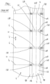
Figure 1 shows a top view of a length of film material for making tobacco pouches according to the prior art. -
Figure 2 shows an isometric view of a tobacco pouch according to the prior art. -
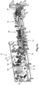
Figures 3A and3B show isometric views of a tobacco pouch making system according to the invention. -
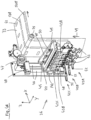
Figure 4A shows an isometric view of an adhesive application station to be used in a method and a system according to the invention. -
Figure 4B shows a side view of an adhesive application station to be used in a method and a system according to the invention. -
Figure 4C shows an exploded isometric view of an adhesive nozzle to be used in a method and a system according to the invention. -
Figure 5 shows a top view of a length of film material. -
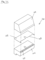
Figure 6A shows a sectional isometric view of an adhesive nozzle for applying flap adhesive regions. -
Figure 6B show a top view of a film material according to the invention having an alternative layout of adhesive bands. -
Figure 7 shows an isometric view of an example of a tobacco pouch. -
Figure 8 shows an isometric view of an alternative example of a tobacco pouch. -
Figure 9 shows a heat welding station for welding the mouth of the tobacco pouch. - Turning to
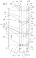
figures 1 and2 , alength 1 of film material and a pouch 2 made from the film material according to the prior art are shown. The film material is elongate and generally provided on a roll from which it is unspooled during the making of the tobacco pouches. The film material comprises alongitudinal fold line 3 which is issued to fold afold section 4 of the film material onto itself. The film material further comprises aflap section 5 which forms the flap in the resulting pouch. - Cut
lines 6 extend transverse to the mainlongitudinal direction 7 across the film material. The cut lines 6 define the lines along which the individual pouches 2 are cut and mark theright side 8A and left side 8B of the individual pouches. - Two
bands 9A, 9B of wax extend in a direction parallel to the mainlongitudinal direction 7 of the film material. Thebands 9A, 9B are provided on the film material prior to the winding of the film material onto the roll. Thebands 9A, 9B have essentially a same length as the length of the film material itself. - Furthermore,
weld regions 10 are indicated with dashed lines. Theweld regions 10 are the regions in which heat welds are applied prior to the cutting process. The heat welds interconnect a front part 11A and arear part 11B of the foldedsection 4 and form thecompartment 14 of the tobacco pouch. The cutting operation along thecutting lines 6 cut eachweld regions 10 in aright weld region 10A and aleft weld region 10B. - The
bands 9A, 9B of wax cross theweld regions 10 atcrossing zones - Turning in particular to
figure 2 , the consequence of the crossing zones is shown. The individual pouch 2 comprises acompartment 14 defined by afront part 15 and arear part 16, a bottom fold 3' and theright seam 10A and leftseam 10B. The pouch has aflap 18 and amouth 19. After filling of the tobacco pouch, the tobacco pouch 2 is closed by anon-permanent seal 20 at themouth 19. Thenon-permanent seal 20 extends along the length of themouth 19. Thenon-permanent seal 20 is formed by the twobands 9A, 9B of wax which are folded onto one another and are heated with a heat application device. The wax melts and thefront part 15 and therear part 16 are attached to one another. The wax is strong enough to form a non-permanent seal, yet weak enough to allow a user to open the mouth upon first use. - Although this works fine, there is a disadvantage in that the
crossing zones weak spots 21 at the sides of the tobacco pouch. At the weak spots, the heat welds of the sides have a low quality and may rip open. The weak spots may in particular become a problem after first use of the tobacco pouch, when the mouth is open and the non-permanent seal has been broken. - Turning to
figures 3A and3B , the tobaccopouch making system 30 according to the invention is shown. The system comprises aroller support 31 for a supporting aroll 32 offilm material 33. The system further comprisesvarious guides 35 for guiding the film material through the system. Most guides 35 are rollers. The various parts are mounted on acommon frame 34. - The system comprises an
adhesive application station 36. Downstream of the adhesive application station, afolding station 37 is provided. Further downstream, a firstheat welding station 38 is provided. Downstream from the firstheat welding station 38, a cuttingstation 39 is provided.
The adhesive (such as wax) is applied at the adhesive application station. Thefolding station 37 is used for folding the film material onto itself along at least one bottom fold which extends lengthwise of the film material. Thefolding station 37 may optionally provide a second fold for folding the flap onto itself, as is further explained below. - The heat welds which form the sides of the pouch are applied in the first
heat welding station 38. The firstheat welding station 38 comprising at least oneheating element 40 for making aright seam 10B and aleft seam 10A in the film material for forming aright side 8A and a left side 8B of the tobacco pouches 2 which are to be formed. In this case, fourheating elements 40 are provided. - A
first buffer station 41 is provided between thefolding station 37 and the firstheat welding station 38. Thefirst buffer station 41 turns an essentially continuous movement of the film material upstream of thefirst buffer station 41 into a start-stop movement of the film material downstream of thefirst buffer station 41. The first heat welding station applies the heat weld during a stationary time period in which the film material is held stationary at the first heat welding station. - The
system 30 comprises various sensors for measuring the position and speed of the film material. - Turning to
figures 4A and4B , theadhesive application station 36 is shown in more detail. Theadhesive application station 36 comprises threeadhesive nozzle assemblies 42A, 42B, 42C, generally indicated with numeral 42. Each adhesive nozzle assembly 42 is mounted on arespective nozzle support 43A, 43B, 43C with aclamp 45. Each nozzle support is mounted on acommon support 44. Thecommon support 44 comprises aslider 144 which is guided byguide rods 46 and can slide along theguide rods 46. Theguide rods 46 extend between two end blocks 48. - It is noted that a different number of adhesive nozzles is also possible, such as one or two, or more than three.
- The common support is adjustable in the Z-direction with an
adjustment device 47. The nozzle supports can be moved in the Y-direction (which is the direction transverse to thedirection 49 of movement of the film material at the adhesive application station) by loosening theclamps 45 and sliding the nozzle supports along arail 50 in thecommon support 44. Each adhesive nozzle can also be adjusted in the X-direction, toward and away from the film material, by an X-adjustment device 51. - Each adhesive nozzle assembly comprises an
adhesive inlet 52 via which the adhesive is fed to the nozzle. Each adhesive nozzle assembly 42 comprises acontrol line connector 53 to which a control line can be connected via which the adhesive nozzle assembly 42 is connected to acontrol unit 54, schematically indicated infig. 4B . - The adhesive application station comprises a first
adhesive nozzle assembly 42A and a second adhesive nozzle assembly 42B positioned at a distance from one another. - The
adhesive application station 36 is configured to apply adhesive while the film material is being conveyed along the adhesive nozzle in thedirection 49. In other words, the adhesive is applied on a moving surface. Theguide 35 is configured to move thefilm material 33 in anupward direction 49 along the adhesive application station. - Turning in particular to
figures 4B and4C , eachadhesive nozzle assembly 42A, 42B, 42C comprises an adhesive nozzle 100A, 100B,100C, generally indicated as 100. - Each adhesive nozzle comprises an
upper part 105, alower part 106 and ashim plate 107 which is very thin and which defines a width of the outflow opening of the nozzle between the upper part and the lower part. Achannel 107 is provided between the upper and lower part. Theshim plate 107 has arecess 108 in the forward side. In the assembled state of thenozzle 100, the recess defines the outflow opening. If the recess needs to be changed, the nozzle can be taken apart and a shim plate of a different shape or thickness can be used. - The outflow opening is a relatively long and narrow gap. It has a length and a width. The length of the outflow opening is more than 10 times the width, in particular more than 30 times the width. The gap may extend horizontally and may extend at a right angle to the transport direction of the film material.
- Turning to
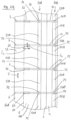
figure 5 , the first andsecond nozzles 42A, 42B are configured for applying afirst row 70A offirst bands 55A and asecond row 70B ofsecond bands 55B of adhesive at regular intervals along the film, wherein the folding station is configured for folding the first and second band of adhesive onto each other. Thecontrol unit 54 is configured for activating and de-activating the adhesive nozzles 42 for applying twoelongate bands free zones width 57 which is equal than or greater than thewidth 58 of theweld regions 10. As a result, there are no crossing zones 13. - The
adhesive bands 55Alongitudinal direction 7 of thefilm material 33, Thefirst bands 55A andsecond bands 55B of adhesive have a substantially same length 60 and a substantiallysame width 61 and are located at a substantially same distance 62 from thebottom fold line 3. - Turning to
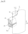
figures 6A and6B , in another embodiment, the adhesive application station comprises at least one flap adhesive nozzle 42C (also referred to as a third nozzle 42C) configured for providing at row 70C ofbands 63 of flap adhesive on aregion 5 of the film material which forms the flap. In this embodiment, the tobacco pouch making system comprises a flap folding station (not shown) for folding afront flap part 64A onto a rear flap part 65B along aflap fold line 65. - It is noted that
figure 6A is a sectional view. Therefore, only half of the flapadhesive region 63 is shown, and this half has a length L2/2. - In this embodiment, the tobacco pouch making system will comprise a longer heating element for heating the flap
adhesive bands 63 of the folded flap in order to provide a non-permanent seal which interconnects thefront flap part 64A onto therear flap part 64B of the folded flap. It is noted that the heating element for making the seams is also used for welding the adhesive regions into a non-permanent seal. The temperature may also be the same. - The adhesive application station comprises a reservoir (not shown) which holds the adhesive, for example wax.
- Generally, the tobacco pouch making system will be followed in line by a system which comprises a second heat welding station 120 (also referred to as a mouth welding station) positioned downstream from the cutting station and downstream from a filling station configured for applying heat at the mouth of the tobacco pouch, thereby melting the adhesive and closing the mouth of the compartment with a non-permanent mouth seal. See also
figure 9 and the description below. - Turning to
figure 7 , the showntobacco pouch 80 is formed with the layout of the film material shown infigure 5 . In this embodiment, the third adhesive nozzle 42C is inactive or may even be removed. Thetobacco pouch 80 is made from apiece 81 of a film material. A bottom part of the piece of film material is folded onto itself along at least one bottom fold 3'. The tobacco pouch comprises aright side seam 10A and aleft side seam 10B which extend along respectively aright side 8A and a left side 8B of the folded section. - Similar to the tobacco pouch 2 of the prior art, the
tobacco pouch 80 according to the invention comprises acompartment 14 defined by afront part 15 and arear part 16, a bottom fold 3' and theright seam 10A and leftseam 10B. The pouch has aflap 18 and amouth 19. - At least one
band band 55A is provided on arear section 16 of the film material, and theband 55B is provided on thefront section 15 of film material. The front part of the pouch is attached to a rear part of the pouch at the mouth via the adhesive, wherein the adhesive forms a non-permanent seal, wherein the band of adhesive does not extend into the seams but ends at the left seam and right seam. - The
bands ends 75 of thebands seams seams - The
right seam 10A and theleft seam 10B are free of any weakened zones which result from adhesive material being present in the region of the seam. - Turning to
figures 8 ,6A and6B another example of thetobacco pouch 80 is shown which is manufactured while using the third adhesive nozzle 42C, i.e. the flap adhesive nozzle. The tobacco pouch is made with the layout of the film material shown infigures 6A and6B . - Flap
adhesive regions 63 have been provided on theflap section 5 of the film material. The flapadhesive regions 63 extend on both sides of the cutting lines 6. The flapadhesive regions 63 extend from theflap fold line 65 over a distance L2 in the direction of themouth section 19. The flapadhesive regions 63 have a width L3 which corresponds to the width of theseams 10. However, the width L3 may also be different than the width of theseams 10. - The
flap 18 is folded onto itself along aflap fold 84. The flap is divided into aforward flap section 64A and arear flap section 64B. Thetobacco pouch 80 comprises at least oneflap adhesive region 63A, 63B via which thefront section 64A of the flap is attached to the rear flap section 64b, the flap adhesive region(s) forming a non-permanent seal which allows the user to unfold the flap section by tearing the flap seal loose. - In the shown example of
figure 8 , the flapadhesive regions 63A, 63B are provided as elongate bands on the left and right side of the flap. However, different configurations are also possible. For instance, a single central flapadhesive region 86 may be provided as indicated with dashed lines infigure 8 . Also, theelongate band 63A,63B may be provided as a series of dots or short bands of adhesive. - When the user opens the pouch for the first time, he can simply tear loose the
front section 64A from the rear section, in order to extend the effective length of theflap 18. The flap may increase 30-70 percent in length. In the extended state the flap may be folded over the entire compartment of the tobacco pouch. - Turning to
figure 9 , aheat welding station 120 for closing the mouth of thetobacco pouch 80 is shown. The tobacco pouches are moved in front of aheating element 121 in a start stop movement. When the tobacco pouch has stopped in front of theheat welding station 120, theheat welding element 121 is pressed against themouth 19 and the wax melts. Theheat welding element 121 is subsequently retracted and the wax solidifies, thereby forming the non-permanent seal. - The
heat welding station 120 comprises a base 123 which can be mounted to the frame, ahorizontal arm 124 and avertical arm 125 which supports theheating element 121. Obviously different arrangements are possible. - In operation, a
roll 32 is positioned on thesupport 31, and thefilm material 33 is pulled through the assembly line. Thefilm material 33 on the roll may be free of any bands of adhesive. - The film material is conveying by a number of guides and is moved along the
adhesive application station 36 in a continuous motion. - At the
adhesive application station 36, a first row ofbands 55A of adhesive is applied on the film material at regular intervals by ejecting a volume of adhesive from at least oneadhesive nozzle 42A at regular intervals. A second row ofbands 55B of adhesive is applied from a second nozzle 42B. The adhesive may be wax. The adhesive is applied to thefilm material 33 while the film material is being conveyed along the at least one adhesive nozzle in anupward direction 49, in particular vertically upward. - Each
band band 55a, 55B of adhesive material comprises opposite ends 75 which meet the right seam and the left seam. Alternatively, the ends 75 may be located at a distance from the right and left seam. The distance may be between zero and 3 mm. - The
seams 10 may have a width of 3-10 mm. - The intervals between the
bands adhesive nozzles 42A, 42B, 42C for a predetermined first period of time, and de-activating the adhesive nozzles for a predetermined second period of time, and repeating these steps for each tobacco pouch which is to be made. - The
first bands 55A andsecond bands 55B of adhesive have a substantially same length 60 and a substantiallysame width 61 and are provided on either side from thebottom fold line 3 at a same distance 62 from thebottom fold line 3. - A third row of bands may also be applied.
- Next, the
film material 33 is transported to thefolding station 37 where it folded onto itself along at least onebottom fold 3 which extends lengthwise of the film material. Thefirst bands 55A andsecond bands 55B of adhesive are folded onto each other by the making of the at least onebottom fold 3. - Subsequently, the film material is conveyed along a first
heat welding station 38. The first heat welding station welds aright seam 10A and aleft seam 10B with heat. These seams are actually welded as asingle seam 10, and later cut into two separate seams at the cutting station - The
right seam 10A extends along aright side 8A of the pouch which is to be formed and theleft seam 10B extends along a left side 8B of the tobacco pouch which is to be formed. The left andright seam longitudinal direction 7 of the film material, in particular at right angles to the main longitudinal direction. - The
bands longitudinal direction 7 of the film material. - The film material subsequently passes a
second buffer station 72. The buffer changes the pitch distance of the start-stop movement of the film material. - The film material is subsequently conveyed along a cutting
station 39 where the film material is cut at regular intervals along thecutting lines 6 to form individual tobacco pouches. Each tobacco pouch comprises a compartment and a flap. - The filling line may follow directly after the making of the tobacco pouches. The pouches are transported along a conveyor to a filing station where a compartment of each tobacco pouch is filled with tobacco.
- Next, the tobacco pouches may be conveyed to a mouth heat welding station, where heat is applied at the mouth of the tobacco pouch, in the area of the
first band 55A andsecond band 55B of adhesive. The adhesive melts and upon solidifying, the adhesive forms a non-permanent mouth seal which closes the mouth of the tobacco pouch. - In an alternative embodiment, the method comprises:
- providing one or more flap
adhesive regions 63 on aflap section 5 of the film material at theadhesive application station 36, and - folding the flap onto itself along a
flap fold line 65 in thefolding station 37 and - fixing a
forward flap part 64A to arear flap part 64B with a non-permanent seal with the one or more flap adhesive regions by applying heat to the flap section. - Each flap
adhesive region 63 may straddle thecut line 6 along which the film material is cut into individual pouches, and each flap adhesive region may be cut in two parts by the cutting operation. - As required, detailed embodiments of the present invention are disclosed herein; however, it is to be understood that the disclosed embodiments are merely exemplary of the invention, which scope is defined by the appended claims.
Claims (12)
- Method of manufacturing a tobacco pouch (80), the method comprising:- unrolling a film material (33) from a roll (32),- conveying the unrolled film material along an adhesive application station (36) comprising at least one adhesive nozzle (100A, 100B, 100C), and applying at least one row (70A, 70B, 70C) of adhesive regions (55A, 55B, 63) on the film material at regular intervals by ejecting a volume of adhesive from the at least one adhesive nozzle at regular intervals,- folding the film material onto itself along at least one bottom fold (3) which extends lengthwise of the film material,- conveying the film material along a first heat welding station (38) and providing a right seam (10A) and a left seam (10B) in the first heat welding station along at least a right side (8A) and a left side (8B) of the tobacco pouch which is to be formed, the left and right seam extending transverse to a main longitudinal direction (7) of the film material,- conveying the film material along a cutting station (39) and cutting the film material at regular intervals to form individual tobacco pouches,the method further comprising:- filling a compartment (14) of each tobacco pouch with tobacco in a filling station, and- conveying the tobacco pouches to, a second heat welding station and applying heat at the mouth (19) of the tobacco pouch, thereby melting the adhesive and closing the mouth of the compartment with a non-permanent mouth seal.
- Method according to claim 1, wherein the adhesive regions (55A, 55B) of at least one row (70A, 70B) meet the left seam and right seam or end at a distance from the left seam and right seam and do not extend into the left seam and right seam.
- Method according to any of claims 1 - 2, wherein each adhesive region is elongate and has a shape of a band, wherein the elongate bands extend parallel to the main longitudinal direction (7) of the film material, the method comprising applying first bands (55A) and second bands (55B) of adhesive at regular intervals along the film, wherein the first and second bands of adhesive are folded onto each other by the making of the at least one bottom fold.
- Method according to any of the preceding claims, wherein the adhesive is wax.
- Method according to any of the preceding claims, comprising:- providing at least one row (70C) of flap adhesive regions (63) on a flap section (5) of the film material at the adhesive application station (36), and- folding the flap onto itself along a flap fold line (65), and- fixing a forward flap part (64A) to a rear flap part (64B) with a non-permanent seal with the one or more flap adhesive regions by applying heat to the flap section.
- Method according to any of the preceding claims, wherein the adhesive is applied to the film material while the film material is being conveyed along the at least one adhesive nozzle, and wherein in particular the adhesive is applied to the film material while the film material is being conveyed along the at least one adhesive nozzle in an upward direction, more in particular vertically upward.
- Tobacco pouch making system (30) for making tobacco pouches (80), the tobacco pouch making system comprising:- a roll support (31) for supporting a roll (32) of film material (33),- multiple guides (35) for guiding the film material,- an adhesive application station (36) comprising at least one adhesive nozzle (100A, 100B, 100C) for applying one or more rows (70A, 70B, 70C) of adhesive regions (55A, 55B, 63) onto the film material by ejecting a volume of adhesive from the at least one adhesive nozzle at regular intervals,- a folding station (37) for folding the film material onto itself along at least one bottom fold (3') which extends lengthwise of the film material,- a heat welding station (38) comprising at least one heating element (40) for making a right seam (10A) and a left seam (10B) in the film material for forming a right side (8A) and a left side (8B) of the tobacco pouches which are to be formed, the left and the right seam extending transverse to a main longitudinal direction of the film material,- a cutting station (39) for cutting the individual tobacco pouches (80) from the film material,wherein the adhesive application station comprises at least one flap adhesive nozzle (100C) configured for providing at least one row (70C) of flap adhesive regions (63) on a section of the film material which forms the flap, the tobacco pouch making system comprising a flap folding station for folding a front flap part onto a rear flap part along a flap fold line,wherein the heat welding station is configured for fixing the front flap part (64A) to the rear flap part (64B) with a non-permanent seal with the flap adhesive regions by applying heat to the flap section.
- Tobacco pouch making system according to claim 7, wherein the adhesive application station comprises a control unit (54) configured for activating and de-activating the adhesive nozzle for applying at least one row of elongate bands (55A, 55B, 63) of adhesive at regular intervals and with adhesive-free zones (56A, 56B) between the adhesive bands, wherein the at least one row of elongate adhesive bands extends parallel to a main longitudinal direction (7) of the film material.
- Tobacco pouch making system according claim 7 - 8, comprising a first adhesive nozzle (100A) and a second adhesive nozzle (100B) positioned at a distance from one another and configured for applying a first row of adhesive regions and a second row of adhesive regions at regular intervals along the film material, wherein in particular the folding station is configured for folding the first and second adhesive regions onto each other.
- Tobacco pouch making system according to any of claims 7 - 9, wherein an outflow opening of each nozzle has an elongate shape, having a length and a width, wherein the length of the outflow opening is more than 10 times the width, in particular more than 30 times the width.
- Tobacco pouch making system according to any of claims 7 - 10, wherein the nozzles are configured to engage the film material.
- Tobacco pouch making system according to any of claims 7 - 11, wherein the adhesive application station is configured to apply adhesive while the film material is being conveyed along the at least one adhesive nozzle, and wherein in particular the guides are configured to move the film material in an upward direction (49) along the adhesive application station.
Priority Applications (1)
| Application Number | Priority Date | Filing Date | Title |
|---|---|---|---|
| PL16187086T PL3138785T3 (en) | 2015-09-02 | 2016-09-02 | Method and system for manufacturing a tobacco pouch |
Applications Claiming Priority (1)
| Application Number | Priority Date | Filing Date | Title |
|---|---|---|---|
| NL2015390 | 2015-09-02 |
Publications (3)
| Publication Number | Publication Date |
|---|---|
| EP3138785A1 EP3138785A1 (en) | 2017-03-08 |
| EP3138785B1 EP3138785B1 (en) | 2019-01-30 |
| EP3138785B2 true EP3138785B2 (en) | 2023-06-14 |
Family
ID=55178242
Family Applications (1)
| Application Number | Title | Priority Date | Filing Date |
|---|---|---|---|
| EP16187086.0A Not-in-force EP3138785B2 (en) | 2015-09-02 | 2016-09-02 | Method and system for manufacturing a tobacco pouch |
Country Status (4)
| Country | Link |
|---|---|
| EP (1) | EP3138785B2 (en) |
| DK (1) | DK3138785T3 (en) |
| HU (1) | HUE042900T2 (en) |
| PL (1) | PL3138785T3 (en) |
Families Citing this family (1)
| Publication number | Priority date | Publication date | Assignee | Title |
|---|---|---|---|---|
| CN109068727A (en) * | 2016-03-31 | 2018-12-21 | 菲利普莫里斯生产公司 | The bag of extension tabs with cover plate and adherency |
Family Cites Families (22)
| Publication number | Priority date | Publication date | Assignee | Title |
|---|---|---|---|---|
| USRE21887E (en) * | 1941-08-26 | Tobacco pouch | ||
| US2149030A (en) | 1936-08-12 | 1939-02-28 | Humoco Corp | Container and method of making the same |
| US3280860A (en) | 1963-03-27 | 1966-10-25 | Eureka Carlisle Company | Fluid dispenser |
| US3427932A (en) | 1966-07-28 | 1969-02-18 | Philip Morris Inc | Apparatus for attaching container covers by adhesive means |
| US4256526A (en) | 1977-08-10 | 1981-03-17 | Nordson Corporation | Method for applying a hot melt adhesive pattern to a moving substrate |
| DE4117428A1 (en) | 1991-05-28 | 1992-12-03 | H D G Verpackungsmaschinen Gmb | Packing machine with heat sealer using recyclable materials - includes applicator supplying reactivatable hot glue |
| IT1280365B1 (en) * | 1995-02-14 | 1998-01-20 | Gd Spa | SPRAY RUBBER UNIT |
| DE19746834A1 (en) | 1997-10-23 | 1999-04-29 | Huels Chemische Werke Ag | Polyethylene wax as a processing aid for hot melt adhesive compositions |
| DE10109209C1 (en) | 2001-02-26 | 2002-10-10 | Nordenia Deutschland Gronau | Resealable plastic film bag and sealing strips for its manufacture |
| DE20106368U1 (en) * | 2001-04-11 | 2002-08-14 | Bischof und Klein GmbH & Co. KG, 49525 Lengerich | Packaging container made of flexible, weldable material in the form of a sack or bag |
| US7033077B2 (en) * | 2002-07-16 | 2006-04-25 | Peter Taylor | Sealable bags made of plastics or other materials and method of making plastic sheeting for manufacturing sealable bags |
| DE50311548D1 (en) | 2003-01-08 | 2009-07-09 | Focke & Co | Method and device for gluing packaging material |
| DE102004056043A1 (en) * | 2004-11-19 | 2006-05-24 | Focke & Co.(Gmbh & Co. Kg) | Bag for e.g. tobacco portion, has filling and withdrawal openings that are independently arranged at distance from each other, where filling opening is used for filling bag content, and withdrawal opening is provided for withdrawing content |
| DE102005002848A1 (en) | 2005-01-20 | 2006-07-27 | Focke & Co.(Gmbh & Co. Kg) | Bag package and method and apparatus for making the same |
| US8016734B2 (en) | 2007-03-22 | 2011-09-13 | Nordson Corporation | Apparatus and methods for non-contact adhesive dispensing to manufacture bags |
| DE102009008129A1 (en) * | 2009-02-09 | 2010-10-07 | Focke & Co.(Gmbh & Co. Kg) | Method and device for producing bags |
| DE102009040096A1 (en) | 2009-09-04 | 2011-03-10 | Focke & Co.(Gmbh & Co. Kg) | tobacco pouch |
| JP2012179502A (en) | 2011-02-28 | 2012-09-20 | Nordson Corp | Slot nozzle assembly and shim plate |
| DE102011105014A1 (en) | 2011-06-08 | 2012-12-13 | Focke & Co. (Gmbh & Co. Kg) | Bag for tobacco and method and apparatus for manufacturing |
| DE202011050614U1 (en) | 2011-07-01 | 2011-10-24 | Huhtamaki Ronsberg, Zweigniederlassung Der Huhtamaki Deutschland Gmbh & Co. Kg | Resealable container |
| EP3009016B1 (en) | 2014-10-14 | 2017-11-29 | Reemtsma Cigarettenfabriken GmbH | Pouch with slide-in pocket |
| DE102015001027A1 (en) | 2014-11-27 | 2016-06-02 | Focke & Co. (Gmbh & Co. Kg) | Method and device for producing cigarette packets |
-
2016
- 2016-09-02 HU HUE16187086A patent/HUE042900T2/en unknown
- 2016-09-02 EP EP16187086.0A patent/EP3138785B2/en not_active Not-in-force
- 2016-09-02 PL PL16187086T patent/PL3138785T3/en unknown
- 2016-09-02 DK DK16187086.0T patent/DK3138785T3/en active
Also Published As
| Publication number | Publication date |
|---|---|
| EP3138785B1 (en) | 2019-01-30 |
| PL3138785T3 (en) | 2019-07-31 |
| EP3138785A1 (en) | 2017-03-08 |
| DK3138785T3 (en) | 2019-04-23 |
| HUE042900T2 (en) | 2019-07-29 |
Similar Documents
| Publication | Publication Date | Title |
|---|---|---|
| EP2383109B1 (en) | Bag-making machine | |
| DE2744640C2 (en) | Method and device for welding parts of a container which consists of a paper coated with a thermoplastic material | |
| WO2008095212A1 (en) | Method for the production of web sections from flexible web material, and for the production of packaging containers | |
| US4597750A (en) | Insertion of draw tape strips in draw tape bag manufacture | |
| EP3292996A1 (en) | Bag making machine | |
| DE2611242A1 (en) | DEVICE FOR APPLYING A MOLTEN ADHESIVE LAYER, IN PARTICULAR FOR THE PRODUCTION OF A BINDING PROCESS | |
| EP2532513A2 (en) | Bag for tobacco and method and device for producing same | |
| CH398061A (en) | Device for welding thermoplastic foils | |
| DE2819887C2 (en) | Device for producing an arrangement having a carrier tape and flat workpieces arranged on top of one another in scales for storing the workpieces | |
| EP3162730B1 (en) | Device and method for manufacturing film bags | |
| EP3138785B2 (en) | Method and system for manufacturing a tobacco pouch | |
| DE3612136C2 (en) | ||
| EP0084880A2 (en) | Device for tranversely cutting webs | |
| DE3105146A1 (en) | "METHOD AND DEVICE FOR CONTINUOUSLY PRODUCING ENDLESS DEFORMABLE TUBES FROM A LAMINATE FILM TAPE" | |
| DE2914696C2 (en) | Device for applying rider tapes provided with an adhesive to the flat front edges of hose sections or sacks | |
| US6364978B1 (en) | Method and apparatus for producing a filter material | |
| EP2998108B1 (en) | Pouch maker for making block-bottom tobacco pouches | |
| DE10104002B4 (en) | Method for tempering plastic films to be bonded and device for bonding plastic film with temperature-controlled transport roller | |
| JP5046576B2 (en) | Plastic bag and manufacturing method thereof | |
| DE1611643A1 (en) | Method and device for the production of a multilayer collapsible bag | |
| EP3277595A1 (en) | Bag web and method for making such a bag web | |
| EP3326804B1 (en) | Packaging film and device and method for manufacturing same | |
| ITBO20110272A1 (en) | DEVICE FOR THE TREATMENT OF FILTERING MATERIAL FOR SMOKE ITEMS. | |
| WO2026012626A1 (en) | Bottom-forming station and method for forming a fold-over bottom on a fabric tube piece | |
| EP3663080A1 (en) | Device and method for manufacturing film bags |
Legal Events
| Date | Code | Title | Description |
|---|---|---|---|
| PUAI | Public reference made under article 153(3) epc to a published international application that has entered the european phase |
Free format text: ORIGINAL CODE: 0009012 |
|
| STAA | Information on the status of an ep patent application or granted ep patent |
Free format text: STATUS: THE APPLICATION HAS BEEN PUBLISHED |
|
| AK | Designated contracting states |
Kind code of ref document: A1 Designated state(s): AL AT BE BG CH CY CZ DE DK EE ES FI FR GB GR HR HU IE IS IT LI LT LU LV MC MK MT NL NO PL PT RO RS SE SI SK SM TR |
|
| AX | Request for extension of the european patent |
Extension state: BA ME |
|
| TPAC | Observations filed by third parties |
Free format text: ORIGINAL CODE: EPIDOSNTIPA |
|
| STAA | Information on the status of an ep patent application or granted ep patent |
Free format text: STATUS: REQUEST FOR EXAMINATION WAS MADE |
|
| 17P | Request for examination filed |
Effective date: 20170904 |
|
| RBV | Designated contracting states (corrected) |
Designated state(s): AL AT BE BG CH CY CZ DE DK EE ES FI FR GB GR HR HU IE IS IT LI LT LU LV MC MK MT NL NO PL PT RO RS SE SI SK SM TR |
|
| GRAP | Despatch of communication of intention to grant a patent |
Free format text: ORIGINAL CODE: EPIDOSNIGR1 |
|
| STAA | Information on the status of an ep patent application or granted ep patent |
Free format text: STATUS: GRANT OF PATENT IS INTENDED |
|
| INTG | Intention to grant announced |
Effective date: 20171027 |
|
| RIN1 | Information on inventor provided before grant (corrected) |
Inventor name: VOLKERS, JACOB Inventor name: WOLF, JAN Inventor name: BULK, MARTINUS JOHANNES |
|
| GRAJ | Information related to disapproval of communication of intention to grant by the applicant or resumption of examination proceedings by the epo deleted |
Free format text: ORIGINAL CODE: EPIDOSDIGR1 |
|
| STAA | Information on the status of an ep patent application or granted ep patent |
Free format text: STATUS: REQUEST FOR EXAMINATION WAS MADE |
|
| INTC | Intention to grant announced (deleted) | ||
| GRAP | Despatch of communication of intention to grant a patent |
Free format text: ORIGINAL CODE: EPIDOSNIGR1 |
|
| STAA | Information on the status of an ep patent application or granted ep patent |
Free format text: STATUS: GRANT OF PATENT IS INTENDED |
|
| INTG | Intention to grant announced |
Effective date: 20180405 |
|
| GRAS | Grant fee paid |
Free format text: ORIGINAL CODE: EPIDOSNIGR3 |
|
| GRAJ | Information related to disapproval of communication of intention to grant by the applicant or resumption of examination proceedings by the epo deleted |
Free format text: ORIGINAL CODE: EPIDOSDIGR1 |
|
| GRAL | Information related to payment of fee for publishing/printing deleted |
Free format text: ORIGINAL CODE: EPIDOSDIGR3 |
|
| STAA | Information on the status of an ep patent application or granted ep patent |
Free format text: STATUS: REQUEST FOR EXAMINATION WAS MADE |
|
| INTC | Intention to grant announced (deleted) | ||
| GRAP | Despatch of communication of intention to grant a patent |
Free format text: ORIGINAL CODE: EPIDOSNIGR1 |
|
| STAA | Information on the status of an ep patent application or granted ep patent |
Free format text: STATUS: GRANT OF PATENT IS INTENDED |
|
| INTG | Intention to grant announced |
Effective date: 20180919 |
|
| GRAA | (expected) grant |
Free format text: ORIGINAL CODE: 0009210 |
|
| STAA | Information on the status of an ep patent application or granted ep patent |
Free format text: STATUS: THE PATENT HAS BEEN GRANTED |
|
| AK | Designated contracting states |
Kind code of ref document: B1 Designated state(s): AL AT BE BG CH CY CZ DE DK EE ES FI FR GB GR HR HU IE IS IT LI LT LU LV MC MK MT NL NO PL PT RO RS SE SI SK SM TR |
|
| REG | Reference to a national code |
Ref country code: GB Ref legal event code: FG4D |
|
| REG | Reference to a national code |
Ref country code: CH Ref legal event code: EP |
|
| REG | Reference to a national code |
Ref country code: AT Ref legal event code: REF Ref document number: 1093069 Country of ref document: AT Kind code of ref document: T Effective date: 20190215 |
|
| REG | Reference to a national code |
Ref country code: IE Ref legal event code: FG4D |
|
| REG | Reference to a national code |
Ref country code: DE Ref legal event code: R096 Ref document number: 602016009600 Country of ref document: DE |
|
| REG | Reference to a national code |
Ref country code: NL Ref legal event code: FP |
|
| REG | Reference to a national code |
Ref country code: DK Ref legal event code: T3 Effective date: 20190415 |
|
| REG | Reference to a national code |
Ref country code: LT Ref legal event code: MG4D |
|
| REG | Reference to a national code |
Ref country code: HU Ref legal event code: AG4A Ref document number: E042900 Country of ref document: HU |
|
| PG25 | Lapsed in a contracting state [announced via postgrant information from national office to epo] |
Ref country code: FI Free format text: LAPSE BECAUSE OF FAILURE TO SUBMIT A TRANSLATION OF THE DESCRIPTION OR TO PAY THE FEE WITHIN THE PRESCRIBED TIME-LIMIT Effective date: 20190130 Ref country code: NO Free format text: LAPSE BECAUSE OF FAILURE TO SUBMIT A TRANSLATION OF THE DESCRIPTION OR TO PAY THE FEE WITHIN THE PRESCRIBED TIME-LIMIT Effective date: 20190430 Ref country code: ES Free format text: LAPSE BECAUSE OF FAILURE TO SUBMIT A TRANSLATION OF THE DESCRIPTION OR TO PAY THE FEE WITHIN THE PRESCRIBED TIME-LIMIT Effective date: 20190130 Ref country code: SE Free format text: LAPSE BECAUSE OF FAILURE TO SUBMIT A TRANSLATION OF THE DESCRIPTION OR TO PAY THE FEE WITHIN THE PRESCRIBED TIME-LIMIT Effective date: 20190130 Ref country code: PT Free format text: LAPSE BECAUSE OF FAILURE TO SUBMIT A TRANSLATION OF THE DESCRIPTION OR TO PAY THE FEE WITHIN THE PRESCRIBED TIME-LIMIT Effective date: 20190530 Ref country code: LT Free format text: LAPSE BECAUSE OF FAILURE TO SUBMIT A TRANSLATION OF THE DESCRIPTION OR TO PAY THE FEE WITHIN THE PRESCRIBED TIME-LIMIT Effective date: 20190130 |
|
| REG | Reference to a national code |
Ref country code: AT Ref legal event code: MK05 Ref document number: 1093069 Country of ref document: AT Kind code of ref document: T Effective date: 20190130 |
|
| PG25 | Lapsed in a contracting state [announced via postgrant information from national office to epo] |
Ref country code: LV Free format text: LAPSE BECAUSE OF FAILURE TO SUBMIT A TRANSLATION OF THE DESCRIPTION OR TO PAY THE FEE WITHIN THE PRESCRIBED TIME-LIMIT Effective date: 20190130 Ref country code: GR Free format text: LAPSE BECAUSE OF FAILURE TO SUBMIT A TRANSLATION OF THE DESCRIPTION OR TO PAY THE FEE WITHIN THE PRESCRIBED TIME-LIMIT Effective date: 20190501 Ref country code: HR Free format text: LAPSE BECAUSE OF FAILURE TO SUBMIT A TRANSLATION OF THE DESCRIPTION OR TO PAY THE FEE WITHIN THE PRESCRIBED TIME-LIMIT Effective date: 20190130 Ref country code: BG Free format text: LAPSE BECAUSE OF FAILURE TO SUBMIT A TRANSLATION OF THE DESCRIPTION OR TO PAY THE FEE WITHIN THE PRESCRIBED TIME-LIMIT Effective date: 20190430 Ref country code: IS Free format text: LAPSE BECAUSE OF FAILURE TO SUBMIT A TRANSLATION OF THE DESCRIPTION OR TO PAY THE FEE WITHIN THE PRESCRIBED TIME-LIMIT Effective date: 20190530 Ref country code: RS Free format text: LAPSE BECAUSE OF FAILURE TO SUBMIT A TRANSLATION OF THE DESCRIPTION OR TO PAY THE FEE WITHIN THE PRESCRIBED TIME-LIMIT Effective date: 20190130 |
|
| REG | Reference to a national code |
Ref country code: DE Ref legal event code: R026 Ref document number: 602016009600 Country of ref document: DE |
|
| PLBI | Opposition filed |
Free format text: ORIGINAL CODE: 0009260 |
|
| PG25 | Lapsed in a contracting state [announced via postgrant information from national office to epo] |
Ref country code: EE Free format text: LAPSE BECAUSE OF FAILURE TO SUBMIT A TRANSLATION OF THE DESCRIPTION OR TO PAY THE FEE WITHIN THE PRESCRIBED TIME-LIMIT Effective date: 20190130 Ref country code: RO Free format text: LAPSE BECAUSE OF FAILURE TO SUBMIT A TRANSLATION OF THE DESCRIPTION OR TO PAY THE FEE WITHIN THE PRESCRIBED TIME-LIMIT Effective date: 20190130 Ref country code: SK Free format text: LAPSE BECAUSE OF FAILURE TO SUBMIT A TRANSLATION OF THE DESCRIPTION OR TO PAY THE FEE WITHIN THE PRESCRIBED TIME-LIMIT Effective date: 20190130 Ref country code: AL Free format text: LAPSE BECAUSE OF FAILURE TO SUBMIT A TRANSLATION OF THE DESCRIPTION OR TO PAY THE FEE WITHIN THE PRESCRIBED TIME-LIMIT Effective date: 20190130 |
|
| PLAX | Notice of opposition and request to file observation + time limit sent |
Free format text: ORIGINAL CODE: EPIDOSNOBS2 |
|
| 26 | Opposition filed |
Opponent name: FOCKE & CO. (GMBH & CO. KG) Effective date: 20191017 |
|
| PG25 | Lapsed in a contracting state [announced via postgrant information from national office to epo] |
Ref country code: SM Free format text: LAPSE BECAUSE OF FAILURE TO SUBMIT A TRANSLATION OF THE DESCRIPTION OR TO PAY THE FEE WITHIN THE PRESCRIBED TIME-LIMIT Effective date: 20190130 |
|
| PG25 | Lapsed in a contracting state [announced via postgrant information from national office to epo] |
Ref country code: AT Free format text: LAPSE BECAUSE OF FAILURE TO SUBMIT A TRANSLATION OF THE DESCRIPTION OR TO PAY THE FEE WITHIN THE PRESCRIBED TIME-LIMIT Effective date: 20190130 |
|
| PG25 | Lapsed in a contracting state [announced via postgrant information from national office to epo] |
Ref country code: SI Free format text: LAPSE BECAUSE OF FAILURE TO SUBMIT A TRANSLATION OF THE DESCRIPTION OR TO PAY THE FEE WITHIN THE PRESCRIBED TIME-LIMIT Effective date: 20190130 |
|
| PLAF | Information modified related to communication of a notice of opposition and request to file observations + time limit |
Free format text: ORIGINAL CODE: EPIDOSCOBS2 |
|
| PG25 | Lapsed in a contracting state [announced via postgrant information from national office to epo] |
Ref country code: TR Free format text: LAPSE BECAUSE OF FAILURE TO SUBMIT A TRANSLATION OF THE DESCRIPTION OR TO PAY THE FEE WITHIN THE PRESCRIBED TIME-LIMIT Effective date: 20190130 |
|
| PG25 | Lapsed in a contracting state [announced via postgrant information from national office to epo] |
Ref country code: MC Free format text: LAPSE BECAUSE OF FAILURE TO SUBMIT A TRANSLATION OF THE DESCRIPTION OR TO PAY THE FEE WITHIN THE PRESCRIBED TIME-LIMIT Effective date: 20190130 |
|
| REG | Reference to a national code |
Ref country code: CH Ref legal event code: PL |
|
| PLBB | Reply of patent proprietor to notice(s) of opposition received |
Free format text: ORIGINAL CODE: EPIDOSNOBS3 |
|
| PG25 | Lapsed in a contracting state [announced via postgrant information from national office to epo] |
Ref country code: CH Free format text: LAPSE BECAUSE OF NON-PAYMENT OF DUE FEES Effective date: 20190930 Ref country code: LI Free format text: LAPSE BECAUSE OF NON-PAYMENT OF DUE FEES Effective date: 20190930 Ref country code: IE Free format text: LAPSE BECAUSE OF NON-PAYMENT OF DUE FEES Effective date: 20190902 Ref country code: LU Free format text: LAPSE BECAUSE OF NON-PAYMENT OF DUE FEES Effective date: 20190902 |
|
| PG25 | Lapsed in a contracting state [announced via postgrant information from national office to epo] |
Ref country code: FR Free format text: LAPSE BECAUSE OF NON-PAYMENT OF DUE FEES Effective date: 20190930 |
|
| PG25 | Lapsed in a contracting state [announced via postgrant information from national office to epo] |
Ref country code: CY Free format text: LAPSE BECAUSE OF FAILURE TO SUBMIT A TRANSLATION OF THE DESCRIPTION OR TO PAY THE FEE WITHIN THE PRESCRIBED TIME-LIMIT Effective date: 20190130 |
|
| PG25 | Lapsed in a contracting state [announced via postgrant information from national office to epo] |
Ref country code: MT Free format text: LAPSE BECAUSE OF FAILURE TO SUBMIT A TRANSLATION OF THE DESCRIPTION OR TO PAY THE FEE WITHIN THE PRESCRIBED TIME-LIMIT Effective date: 20190130 |
|
| REG | Reference to a national code |
Ref country code: CH Ref legal event code: PK Free format text: BERICHTIGUNGEN |
|
| RIC2 | Information provided on ipc code assigned after grant |
Ipc: B65B 59/00 20060101ALN20220314BHEP Ipc: B31B 170/10 20170101ALN20220314BHEP Ipc: B31B 160/10 20170101ALN20220314BHEP Ipc: B31B 155/00 20170101ALN20220314BHEP Ipc: B31B 70/62 20170101ALN20220314BHEP Ipc: A24F 23/02 20060101ALN20220314BHEP Ipc: B65D 75/58 20060101ALN20220314BHEP Ipc: B65B 51/14 20060101ALI20220314BHEP Ipc: B65B 9/093 20120101ALI20220314BHEP Ipc: B65B 61/06 20060101ALI20220314BHEP Ipc: B65B 51/02 20060101ALI20220314BHEP Ipc: B65B 29/00 20060101ALI20220314BHEP Ipc: B65D 33/22 20060101AFI20220314BHEP |
|
| PG25 | Lapsed in a contracting state [announced via postgrant information from national office to epo] |
Ref country code: MK Free format text: LAPSE BECAUSE OF FAILURE TO SUBMIT A TRANSLATION OF THE DESCRIPTION OR TO PAY THE FEE WITHIN THE PRESCRIBED TIME-LIMIT Effective date: 20190130 |
|
| PGFP | Annual fee paid to national office [announced via postgrant information from national office to epo] |
Ref country code: NL Payment date: 20220926 Year of fee payment: 7 Ref country code: GB Payment date: 20220923 Year of fee payment: 7 Ref country code: DK Payment date: 20220922 Year of fee payment: 7 Ref country code: DE Payment date: 20220922 Year of fee payment: 7 Ref country code: CZ Payment date: 20220824 Year of fee payment: 7 |
|
| PGFP | Annual fee paid to national office [announced via postgrant information from national office to epo] |
Ref country code: PL Payment date: 20220823 Year of fee payment: 7 Ref country code: HU Payment date: 20220822 Year of fee payment: 7 Ref country code: BE Payment date: 20220923 Year of fee payment: 7 |
|
| PGFP | Annual fee paid to national office [announced via postgrant information from national office to epo] |
Ref country code: IT Payment date: 20220926 Year of fee payment: 7 |
|
| PUAH | Patent maintained in amended form |
Free format text: ORIGINAL CODE: 0009272 |
|
| STAA | Information on the status of an ep patent application or granted ep patent |
Free format text: STATUS: PATENT MAINTAINED AS AMENDED |
|
| 27A | Patent maintained in amended form |
Effective date: 20230614 |
|
| AK | Designated contracting states |
Kind code of ref document: B2 Designated state(s): AL AT BE BG CH CY CZ DE DK EE ES FI FR GB GR HR HU IE IS IT LI LT LU LV MC MK MT NL NO PL PT RO RS SE SI SK SM TR |
|
| REG | Reference to a national code |
Ref country code: DE Ref legal event code: R102 Ref document number: 602016009600 Country of ref document: DE |
|
| P01 | Opt-out of the competence of the unified patent court (upc) registered |
Effective date: 20230522 |
|
| PG25 | Lapsed in a contracting state [announced via postgrant information from national office to epo] |
Ref country code: NL Free format text: LAPSE BECAUSE OF FAILURE TO SUBMIT A TRANSLATION OF THE DESCRIPTION OR TO PAY THE FEE WITHIN THE PRESCRIBED TIME-LIMIT Effective date: 20190130 Ref country code: CZ Free format text: LAPSE BECAUSE OF FAILURE TO SUBMIT A TRANSLATION OF THE DESCRIPTION OR TO PAY THE FEE WITHIN THE PRESCRIBED TIME-LIMIT Effective date: 20190130 |
|
| REG | Reference to a national code |
Ref country code: DE Ref legal event code: R119 Ref document number: 602016009600 Country of ref document: DE |
|
| PG25 | Lapsed in a contracting state [announced via postgrant information from national office to epo] |
Ref country code: DK Free format text: LAPSE BECAUSE OF FAILURE TO SUBMIT A TRANSLATION OF THE DESCRIPTION OR TO PAY THE FEE WITHIN THE PRESCRIBED TIME-LIMIT Effective date: 20230614 |
|
| REG | Reference to a national code |
Ref country code: BE Ref legal event code: MM Effective date: 20230930 |
|
| GBPC | Gb: european patent ceased through non-payment of renewal fee |
Effective date: 20230902 |
|
| PG25 | Lapsed in a contracting state [announced via postgrant information from national office to epo] |
Ref country code: GB Free format text: LAPSE BECAUSE OF NON-PAYMENT OF DUE FEES Effective date: 20230902 |
|
| PG25 | Lapsed in a contracting state [announced via postgrant information from national office to epo] |
Ref country code: GB Free format text: LAPSE BECAUSE OF NON-PAYMENT OF DUE FEES Effective date: 20230902 Ref country code: DE Free format text: LAPSE BECAUSE OF NON-PAYMENT OF DUE FEES Effective date: 20240403 |
|
| PG25 | Lapsed in a contracting state [announced via postgrant information from national office to epo] |
Ref country code: HU Free format text: LAPSE BECAUSE OF NON-PAYMENT OF DUE FEES Effective date: 20230903 Ref country code: BE Free format text: LAPSE BECAUSE OF NON-PAYMENT OF DUE FEES Effective date: 20230930 |
|
| PG25 | Lapsed in a contracting state [announced via postgrant information from national office to epo] |
Ref country code: PL Free format text: THE PATENT HAS BEEN ANNULLED BY A DECISION OF A NATIONAL AUTHORITY Effective date: 20230914 |
|
| PG25 | Lapsed in a contracting state [announced via postgrant information from national office to epo] |
Ref country code: PL Free format text: THE PATENT HAS BEEN ANNULLED BY A DECISION OF A NATIONAL AUTHORITY Effective date: 20230914 |
|
| PG25 | Lapsed in a contracting state [announced via postgrant information from national office to epo] |
Ref country code: IT Free format text: LAPSE BECAUSE OF NON-PAYMENT OF DUE FEES Effective date: 20230902 |
|
| PG25 | Lapsed in a contracting state [announced via postgrant information from national office to epo] |
Ref country code: IT Free format text: LAPSE BECAUSE OF NON-PAYMENT OF DUE FEES Effective date: 20230902 |