EP3138483A1 - Bio-information detecting apparatus - Google Patents
Bio-information detecting apparatus Download PDFInfo
- Publication number
- EP3138483A1 EP3138483A1 EP16186664.5A EP16186664A EP3138483A1 EP 3138483 A1 EP3138483 A1 EP 3138483A1 EP 16186664 A EP16186664 A EP 16186664A EP 3138483 A1 EP3138483 A1 EP 3138483A1
- Authority
- EP
- European Patent Office
- Prior art keywords
- examinee
- neck part
- bio
- contact
- band member
- Prior art date
- Legal status (The legal status is an assumption and is not a legal conclusion. Google has not performed a legal analysis and makes no representation as to the accuracy of the status listed.)
- Granted
Links
Images



Classifications
-
- A—HUMAN NECESSITIES
- A61—MEDICAL OR VETERINARY SCIENCE; HYGIENE
- A61B—DIAGNOSIS; SURGERY; IDENTIFICATION
- A61B5/00—Measuring for diagnostic purposes; Identification of persons
- A61B5/02—Detecting, measuring or recording for evaluating the cardiovascular system, e.g. pulse, heart rate, blood pressure or blood flow
- A61B5/0205—Simultaneously evaluating both cardiovascular conditions and different types of body conditions, e.g. heart and respiratory condition
-
- A—HUMAN NECESSITIES
- A61—MEDICAL OR VETERINARY SCIENCE; HYGIENE
- A61B—DIAGNOSIS; SURGERY; IDENTIFICATION
- A61B5/00—Measuring for diagnostic purposes; Identification of persons
- A61B5/24—Detecting, measuring or recording bioelectric or biomagnetic signals of the body or parts thereof
- A61B5/25—Bioelectric electrodes therefor
- A61B5/279—Bioelectric electrodes therefor specially adapted for particular uses
- A61B5/28—Bioelectric electrodes therefor specially adapted for particular uses for electrocardiography [ECG]
-
- A—HUMAN NECESSITIES
- A61—MEDICAL OR VETERINARY SCIENCE; HYGIENE
- A61B—DIAGNOSIS; SURGERY; IDENTIFICATION
- A61B5/00—Measuring for diagnostic purposes; Identification of persons
- A61B5/02—Detecting, measuring or recording for evaluating the cardiovascular system, e.g. pulse, heart rate, blood pressure or blood flow
- A61B5/024—Measuring pulse rate or heart rate
- A61B5/02416—Measuring pulse rate or heart rate using photoplethysmograph signals, e.g. generated by infrared radiation
-
- A—HUMAN NECESSITIES
- A61—MEDICAL OR VETERINARY SCIENCE; HYGIENE
- A61B—DIAGNOSIS; SURGERY; IDENTIFICATION
- A61B5/00—Measuring for diagnostic purposes; Identification of persons
- A61B5/02—Detecting, measuring or recording for evaluating the cardiovascular system, e.g. pulse, heart rate, blood pressure or blood flow
- A61B5/024—Measuring pulse rate or heart rate
- A61B5/02438—Measuring pulse rate or heart rate with portable devices, e.g. worn by the patient
-
- A—HUMAN NECESSITIES
- A61—MEDICAL OR VETERINARY SCIENCE; HYGIENE
- A61B—DIAGNOSIS; SURGERY; IDENTIFICATION
- A61B5/00—Measuring for diagnostic purposes; Identification of persons
- A61B5/145—Measuring characteristics of blood in vivo, e.g. gas concentration or pH-value ; Measuring characteristics of body fluids or tissues, e.g. interstitial fluid or cerebral tissue
- A61B5/1455—Measuring characteristics of blood in vivo, e.g. gas concentration or pH-value ; Measuring characteristics of body fluids or tissues, e.g. interstitial fluid or cerebral tissue using optical sensors, e.g. spectral photometrical oximeters
- A61B5/14551—Measuring characteristics of blood in vivo, e.g. gas concentration or pH-value ; Measuring characteristics of body fluids or tissues, e.g. interstitial fluid or cerebral tissue using optical sensors, e.g. spectral photometrical oximeters for measuring blood gases
-
- A—HUMAN NECESSITIES
- A61—MEDICAL OR VETERINARY SCIENCE; HYGIENE
- A61B—DIAGNOSIS; SURGERY; IDENTIFICATION
- A61B5/00—Measuring for diagnostic purposes; Identification of persons
- A61B5/145—Measuring characteristics of blood in vivo, e.g. gas concentration or pH-value ; Measuring characteristics of body fluids or tissues, e.g. interstitial fluid or cerebral tissue
- A61B5/1455—Measuring characteristics of blood in vivo, e.g. gas concentration or pH-value ; Measuring characteristics of body fluids or tissues, e.g. interstitial fluid or cerebral tissue using optical sensors, e.g. spectral photometrical oximeters
- A61B5/14551—Measuring characteristics of blood in vivo, e.g. gas concentration or pH-value ; Measuring characteristics of body fluids or tissues, e.g. interstitial fluid or cerebral tissue using optical sensors, e.g. spectral photometrical oximeters for measuring blood gases
- A61B5/14552—Details of sensors specially adapted therefor
-
- A—HUMAN NECESSITIES
- A61—MEDICAL OR VETERINARY SCIENCE; HYGIENE
- A61B—DIAGNOSIS; SURGERY; IDENTIFICATION
- A61B5/00—Measuring for diagnostic purposes; Identification of persons
- A61B5/24—Detecting, measuring or recording bioelectric or biomagnetic signals of the body or parts thereof
- A61B5/25—Bioelectric electrodes therefor
-
- A—HUMAN NECESSITIES
- A61—MEDICAL OR VETERINARY SCIENCE; HYGIENE
- A61B—DIAGNOSIS; SURGERY; IDENTIFICATION
- A61B5/00—Measuring for diagnostic purposes; Identification of persons
- A61B5/24—Detecting, measuring or recording bioelectric or biomagnetic signals of the body or parts thereof
- A61B5/25—Bioelectric electrodes therefor
- A61B5/279—Bioelectric electrodes therefor specially adapted for particular uses
- A61B5/28—Bioelectric electrodes therefor specially adapted for particular uses for electrocardiography [ECG]
- A61B5/282—Holders for multiple electrodes
-
- A—HUMAN NECESSITIES
- A61—MEDICAL OR VETERINARY SCIENCE; HYGIENE
- A61B—DIAGNOSIS; SURGERY; IDENTIFICATION
- A61B5/00—Measuring for diagnostic purposes; Identification of persons
- A61B5/24—Detecting, measuring or recording bioelectric or biomagnetic signals of the body or parts thereof
- A61B5/316—Modalities, i.e. specific diagnostic methods
- A61B5/318—Heart-related electrical modalities, e.g. electrocardiography [ECG]
-
- A—HUMAN NECESSITIES
- A61—MEDICAL OR VETERINARY SCIENCE; HYGIENE
- A61B—DIAGNOSIS; SURGERY; IDENTIFICATION
- A61B5/00—Measuring for diagnostic purposes; Identification of persons
- A61B5/68—Arrangements of detecting, measuring or recording means, e.g. sensors, in relation to patient
- A61B5/6801—Arrangements of detecting, measuring or recording means, e.g. sensors, in relation to patient specially adapted to be attached to or worn on the body surface
- A61B5/6802—Sensor mounted on worn items
-
- A—HUMAN NECESSITIES
- A61—MEDICAL OR VETERINARY SCIENCE; HYGIENE
- A61B—DIAGNOSIS; SURGERY; IDENTIFICATION
- A61B5/00—Measuring for diagnostic purposes; Identification of persons
- A61B5/68—Arrangements of detecting, measuring or recording means, e.g. sensors, in relation to patient
- A61B5/6801—Arrangements of detecting, measuring or recording means, e.g. sensors, in relation to patient specially adapted to be attached to or worn on the body surface
- A61B5/6813—Specially adapted to be attached to a specific body part
- A61B5/6822—Neck
-
- A—HUMAN NECESSITIES
- A61—MEDICAL OR VETERINARY SCIENCE; HYGIENE
- A61B—DIAGNOSIS; SURGERY; IDENTIFICATION
- A61B5/00—Measuring for diagnostic purposes; Identification of persons
- A61B5/68—Arrangements of detecting, measuring or recording means, e.g. sensors, in relation to patient
- A61B5/6801—Arrangements of detecting, measuring or recording means, e.g. sensors, in relation to patient specially adapted to be attached to or worn on the body surface
- A61B5/683—Means for maintaining contact with the body
- A61B5/6831—Straps, bands or harnesses
-
- A—HUMAN NECESSITIES
- A61—MEDICAL OR VETERINARY SCIENCE; HYGIENE
- A61B—DIAGNOSIS; SURGERY; IDENTIFICATION
- A61B2562/00—Details of sensors; Constructional details of sensor housings or probes; Accessories for sensors
- A61B2562/02—Details of sensors specially adapted for in-vivo measurements
- A61B2562/0209—Special features of electrodes classified in A61B5/24, A61B5/25, A61B5/283, A61B5/291, A61B5/296, A61B5/053
-
- A—HUMAN NECESSITIES
- A61—MEDICAL OR VETERINARY SCIENCE; HYGIENE
- A61B—DIAGNOSIS; SURGERY; IDENTIFICATION
- A61B2562/00—Details of sensors; Constructional details of sensor housings or probes; Accessories for sensors
- A61B2562/02—Details of sensors specially adapted for in-vivo measurements
- A61B2562/0233—Special features of optical sensors or probes classified in A61B5/00
- A61B2562/0238—Optical sensor arrangements for performing transmission measurements on body tissue
-
- A—HUMAN NECESSITIES
- A61—MEDICAL OR VETERINARY SCIENCE; HYGIENE
- A61B—DIAGNOSIS; SURGERY; IDENTIFICATION
- A61B2562/00—Details of sensors; Constructional details of sensor housings or probes; Accessories for sensors
- A61B2562/06—Arrangements of multiple sensors of different types
- A61B2562/063—Arrangements of multiple sensors of different types in a linear array
Definitions
- the present invention relates to an apparatus to measure bio-information.
- the present invention relates to an apparatus to measure bio-information regarding human heartbeats, such as cardiac potential and pulse waves, and more specifically, to a neck-band type bio-information detecting apparatus attached (or worn) around a human neck part.
- bio-information detecting apparatuses attached to heads, necks, or the like of examinees so as to allow the examinees to relatively freely take exercise.
- a bio-information detecting apparatus configured to include electrodes coming into contact with a neck part of an examinee so as to detect cardiac potential of the examinee, at both ends of a C-shaped neck band attached to the examinee from the back side of his or her neck part, and transmit the potential difference of the electrodes to the outside via radio communication.
- Japanese Patent Application Publication No. 2007-202939 discloses a configuration that provides both ends of a C-shaped neck band as described above with not only measurement means of cardiac potential, but also sensor means to optically measure blood oxygen saturation in the carotid artery of an examinee so as to detect his or her pulse waves. Furthermore, Japanese Patent Application Publication No. 2015-73557 discloses a configuration that provides a C-shaped neck band attached to an examinee from the back side of his or her neck part with sensor means to optically measure blood oxygen saturation.
- a bio-information detecting apparatus configured to include cardiac potential measurement means and pulse wave detecting means to optically measure blood oxygen saturation on a C-shaped neck band of the apparatus attached from the back side of a neck part has an advantage in that the apparatus has a smaller dimension, and does not cause much influence on any exercise taken by an examinee.
- One of the current challenges in bio-information detecting apparatuses including measurement means to measure cardiac potential and pulse waves on neck bands attached around neck parts is to measure cardiac potential and blood oxygen saturation with as high measurement sensitivity as possible. For example, if cardiac potential is measured at a neck part, its measurement part is located apart from a heart; thus measurement sensitivity becomes considerably deteriorated compared with the case of measuring cardiac potential at a chest part near the heart.
- cardiac potential measuring means of a type that has electrodes at both ends of a neck band detects considerably smaller amplitudes of measurement values of cardiac potential.
- elasticity of the neck band is utilized so as to prevent the neck band from dropping off the neck.
- one aim of the present invention is to provide a novel configuration to improve sensitivity of measurement values of cardiac potential and blood oxygen saturation in a bio-information detecting apparatus having measurement means of cardiac potential and pulse waves in a neck band attached around a neck part.
- a bio-information detecting apparatus including: a band member curved in a C-shape, the band member attached in a manner as to extend along a neck part of an examinee from a back side of the neck part toward both lateral sides of the neck part; and a pair of electrodes for cardiac potential measurement of the examinee, the pair of electrodes disposed at positions of the band member that come into contact with right and left skin surfaces of the neck part of the examinee, wherein, of the pair of electrodes, a position of the electrode located on the right of the examinee is located relatively more frontward than a position of the electrode located on the left of the examinee.
- the "band member curved in a C-shape” denotes a member having a neck band structure attached from the back side of the neck part of the examinee, and typically is formed by a flexible or elastic material, such as a plastic material that has been commonly used in this field.
- the "pair of electrodes for cardiac potential measurement” may be electrode pieces commonly used in this field, and each of the electrodes has a dimension of approximately several mm to 2 cm large enough for measuring the cardiac potential.
- the "pair of electrodes for cardiac potential measurement” is arranged on the "band member" in a manner as to be in contact with the right and left skin surfaces of the neck part of the examinee, and the positions of the electrodes are arranged in such a manner that the electrode located on the right of the examinee is disposed relatively more frontward than the position of the electrode located on the left of the examinee.
- the pair of electrodes are arranged on the band member, various configurations of electrode arrangement along the band member may be considered; and according to experiments conducted by the inventors of the present invention, it has been found that if the electrode on the right is disposed more frontward than the electrode on the left, the amplitude of the measured cardiac potential becomes considerably greater than that in the other cases, thereby measuring the cardiac potential in a preferable manner.
- the electrode located on the right of the examinee is disposed relatively more frontward than the position of the electrode located on the left of the examinee, thereby increasing the measurement sensitivity of the cardiac potential.
- the electrode located on the right is disposed in a more frontward region on the band member than the right lateral side of the neck part of the examinee, and the electrode located on the left is disposed at a more backward position on the band member than the left lateral side of the neck part of the examinee, the amplitude of the measured cardiac potential becomes the maximum.
- the electrode on the right may be disposed in a more frontward region on the band member than the right lateral side of the neck part of the examinee, and the electrode on the left may be disposed at a more backward position on the band member than the left lateral side of the neck part of the examinee.
- each contact surface of the pair of electrodes that comes into contact with the skin surface of the neck part of the examinee is in a flat state or in a curved state in a direction in which a center portion of the contact surface protrudes more than a peripheral edge of the contact surface toward the skin surface of the neck part of the examinee, the protrusion being within a range of not more than 1 mm.
- the contact surface of each electrode in order to bring each electrode to stably contact with the neck part of the examinee, for example, it is considered to be preferable that the contact surface of each electrode with the skin surface of the neck part of the examinee is formed to be curved such that the center portion of the contact surface protrudes more than the peripheral edge thereof toward the skin surface of the neck part of the examinee so as to securely contact with the skin surface of the neck part.
- the amplitude of the measured cardiac potential is detected with the most excellent sensitivity, and if the center portion of the contact surface protrudes more than the peripheral edge thereof by more than 1 mm toward the skin surface of the neck part of the examinee, the amplitude of the measured cardiac potential becomes significantly decreased compared with the case of the contact surface having a flat shape.
- the contact surface of each electrode that comes into contact with the skin surface of the neck part of the examinee is in a flat state or in a curved state in a direction in which a center portion of the contact surface protrudes more than a peripheral edge thereof toward the skin surface of the neck part of the examinee, the protrusion being within a range of not more than 1 mm.
- a contact area of each of the pair of electrodes that comes into contact with the skin surface of the neck part of the examinee may be more than 25 mm 2 .
- a bio-information detecting apparatus including: a band member curved in a C-shape, the band member attached in a manner as to extend along a neck part from a back side of the neck part toward both lateral sides of the neck part to a region more frontward than the lateral side of the neck part; and a substrate disposed at a position on the band member that comes into contact with the neck part of the examinee, the substrate having a light emitting part and a light receiving part that are used for optically measuring a blood oxygen saturation for pulse measurement of the examinee, wherein in a state in which the substrate is in contact with a skin surface of the neck part of the examinee, a pressing force of the substrate against the skin surface of the neck part is 0.96 to 1.21[N/cm 2 ].
- the "substrate having a light emitting part and a light receiving part used for optically measuring blood oxygen saturation for pulse measurement” may be any sensor unit optically measuring the blood oxygen saturation in this field, as described in JP 2007-202939 A , for example.
- a substrate for the pulse measurement there might be considered various factors to cause influence on the magnitude of the amplitude of the blood oxygen saturation that is a measurement value obtained when the substrate comes into contact with the skin surface of the examinee. According to the studies by the inventors of the present invention, it has been found that the magnitude of the amplitude of the blood oxygen saturation depends on the pressing force of the sensor unit.
- the pressing force falls within a range of 0.96 to 1.21[N/cm 2 ], the amplitude of the blood oxygen saturation becomes increased, and the change in blood oxygen saturation, that is, the pulse can be detected with a preferable sensitivity.
- a pressing force of the substrate against the skin surface of the neck part is 0.96 to 1.21 [N/cm 2 ].
- Such a pressure adjustment can be achieved by adjusting the elastic force of the band member when the band member is attached around the neck part of the examinee.
- the configuration of setting the pressing force of the substrate for the pulse measurement to be within a range of 0.96 to 1.21[N/cm 2 ] may be applicable to the bio-information detecting apparatus including the configuration regarding the aforementioned electrodes for the cardiac potential measurement. According to this configuration, it is possible to hold the apparatus having the band-like structure curved in a C-shape against the neck part in a manner as not to be out of position by the electrodes and the substrate, thereby measuring both the cardiac potential and the pulse with an excellent sensitivity, which results in advantage.
- the configuration of the above described present invention it is possible to measure cardiac potential and pulse pertinent to human heartbeats with a more excellent sensitivity through the neck-band type apparatus attached around a human neck part, compared with the conventional configuration.
- the neck-band type apparatus attached around a human neck part is portable and allows measurement at portions of an examinee regardless of accessories and clothes, which results in advantage.
- it is expected to improve measurement accuracy of cardiac potential and pulse in a neck-band type bio-information detecting apparatus as above configured, and it is also expected to facilitate measurement of cardiac potential and pulse more than the conventional one, and promote increase in opportunity to use the apparatus.
- a bio-information detecting apparatus 1 of the present invention includes, as a basic configuration thereof, a band member 2 curved in a substantially C-shape, and a pair of electrodes 4a, 4b for cardiac potential measurement fixed on an inner side of the C-shape of the band member 2, and an optical blood saturation measurement unit 5 for pulse wave measurement (referred to as a "pulse measurement unit”, hereinafter).
- a signal processing unit 3 receives potential differences between the electrode 4a and the electrode 4b, and measurement values (light intensity received by a light receiving part as described later) of the pulse measurement unit 5, and includes a radio transmitting unit that transmits the above data to any external processing unit, and this signal processing unit 3 is fixed to the vicinity of the center portion of the C-shaped band member 2.
- the band member 2 may typically be formed by a flexible or elastic material, such as a plastic material or a resin material, or such as a plastic material or a resin material containing a metallic band-like member thereinside.
- the pair of electrodes 4a, 4b may be any electrode elements for cardiac potential measurement used in this field, and the pulse measurement unit 5 may be any (reflecting-type) optical pulse measurement device (substrate including a light emitting part and the light receiving part) used in this field.
- the bio-information detecting apparatus 1 is a so-called neck-band type apparatus, and is configured, as schematically illustrated in FIG. 1B and FIG.
- the band member 2 to which the signal processing unit 3 is fixed is attached in such a manner that a center region of the C-shape of the band member 2 is disposed to a back side of a neck part N of an examinee, and the band member 2 extends along and surrounds the neck part N so that both ends of the C-shape reach respective positions more frontward than both lateral sides (or lateral mid points) Sl, Sr of the neck part N of the examinee.
- the pair of electrodes 4a, 4b are arranged such that respective electrode surfaces come into contact with skin surfaces on the left and right of the neck part N in a state in which the bio-information detecting apparatus 1 is attached (or worn) around the neck part N.
- the pulse measurement unit 5 is arranged with a measurement surface (the light emitting part and the light receiving part) thereof in contact with the skin surface of the neck part N in the state in which the bio-information detecting apparatus 1 is attached around the neck part N.
- the signal processing unit 3 includes, more specifically, a signal processing substrate 3b that receives and processes signals from the pair of electrodes 4a, 4b and the pulse measurement unit 5, and a battery 3a used for driving the electrodes 4a, 4b, the pulse measurement unit 5, and the signal processing substrate 3b.
- the configuration of signal processing in the cardiac potential measurement and the optical pulse measurement in the bio-information detecting apparatus 1 of the aforementioned neck-band type may be any signal processing for cardiac potential measurement and pulse wave measurement.
- the cardiac potential measurement is processed in such a manner that the potential difference between the pair of electrodes 4a and 4b in contact with the skin surfaces of the neck part N of the examinee is successively sent to an amplifier to be amplified, and digitized by an AD converter, and then is processed in the signal processing unit to be sent to any external processing unit.
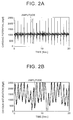
- the potential difference obtained herein is cardiac potential oscillating in accordance with heartbeats, as shown in FIG. 2A .
- a light having a wavelength bandwidth to be absorbed into hemoglobin combined with oxygen in an arterial blood from the light emitting part provided on the measurement surface of the pulse measurement unit 5 in contact with the skin surface of the neck part N of the examinee is radiated onto a surface layer of the skin.
- the light receiving part also referred to as a reflecting-type pulse oxymeter.
- Signals indicating the light intensity of the light received by the light receiving part are successively sent to the amplifier to be amplified, digitalized by the AD converter, and is then processed in the signal processing unit to be sent to any external processing apparatus.
- the light intensity received by the light receiving part is proportional to amount of hemoglobin combined with oxygen in blood (oxygen saturation), and the amount of bloodstream hemoglobin becomes increased or decreased in accordance with the pulse.
- the light intensity received by the light receiving part oscillates, and these oscillations are correspondent to the pulse, as exemplified in FIG. 2B .
- the signals indicating the cardiac potential and the signals indicating the pulse are respectively transmitted from the radio communicating unit to any external processing apparatus.
- one of the challenges to be achieved is how to improve the measurement sensitivity of the cardiac potential and the pulse (oxygen saturation).
- amplitudes of the oscillating waveforms are measured, occurrence of the oscillations, that is, occurrence of the heartbeats or the pulse is successively detected, and then the heart rate and the pulse rate are measured.
- the cardiac potential which has conventionally been measured at a chest part near the heart, is instead measured at the neck part further away from the heart, and thus the amplitude of the cardiac potential is decreased more than that in the case of measurement at the chest part near the heart.
- the pulse measurement change in blood flow rate in the artery is measured, but if the blood is pooled (or restrained) in the vessel, the blood flow rate decreases, and thus the amplitude of the pulse (oxygen saturation) becomes decreased.
- the bio-information detecting apparatus 1 is supposed to be attached around the neck part of the examinee, it is necessary to stably maintain the contact state of the electrodes and the pulse measurement unit with the skin surface even if the body of the examinee moves to some extent.
- the inventors of the present invention have conducted various studies, and as a result, they have found a novel configuration capable of increasing measurement sensitivity of the cardiac potential and the pulse, in particular, the respective amplitudes of the cardiac potential and the pulse.
- the novel configuration in the bio-information detecting apparatus 1 according to the present invention will be described.
- the aforementioned bio-information detecting apparatus 1 is positioned in a stable manner with an elastic force F (applied in a direction vertical to an extending direction of the neck part) of the band member 2 when the bio-information detecting apparatus 1 is attached around the neck part N of the examinee, as schematically illustrated FIG. 3A .
- the pulse measurement unit 5 and the pair of electrodes 4a, 4b that are disposed on the C-shaped inner side of the band member 2 are pressed against the skin surface of the neck part N, as schematically illustrated in FIG. 3B .
- an excessively strong pressing force P causes reduction in blood flow rate due to pooled blood in the vessel, as aforementioned, and thus the measured sensitivity (magnitude of the amplitude of the pulse) becomes decreased.
- the pressing force P is excessively weak, the band member 2 is likely to move, or the pulse measurement unit 5 is likely to be out of contact with the skin surface, and thus the measurement sensitivity also becomes decreased.
- studies have been carried out to determine a preferable range of the pressing force to press the pulse measurement unit 5 against the skin surface in which a measurement value of the pulse measurement unit 5 falls within an acceptable range.
- the bio-information detecting apparatus 1 using plural band members 2 with different elastic forces F was attached to the examinee so as to variously change the pressing force P of the pulse measurement unit 5 against the skin surface, and measure the pulse depending on the various pressing forces P by using the pulse measurement unit 5.
- change in amplitude (defined in FIG. 2B ) obtained from the measurement data of the pulse depending on the various pressing forces exhibits a result as shown in FIG. 3C .
- each point " ⁇ " represents a data plot
- a chain line represents a lower limit value of the acceptable amplitude.
- the amplitude becomes an acceptable value, and in particular, the amplitude becomes the maximum with the pressing force in the vicinity of 1.1[N/cm 2 ].
- This pressing force is equivalent to a force to push down the skin surface by approximately 1 mm.
- the dimension of the band member 2 is so defined as to apply the elastic force F of the band member 2 causing the pressing force of the pulse measurement unit 5 against the skin surface of the neck part that falls within a range of 0.96 to 1.21[N/cm 2 ], more preferably, within a range of approximately 1.1[N/cm 2 ], thereby improving the sensitivity of the pulse measurement.
- a significant pressing force within the above range is applied from the pulse measurement unit 5 onto the neck part so that the apparatus having the band-like structure curved in a C-shape can be held relative to the neck part while preventing the apparatus from being out of position, which attains another advantage (it has been confirmed that the cardiac potential can be measured within the above pressing-force range if the following conditions of the configuration regarding the electrodes are satisfied).
- the amplitude of measured cardiac potential is greatly affected by the arrangement of the pair of electrodes for cardiac potential measurement in a direction along the C-shape of the band member 2 (longitudinal direction of the band member 2), and in particular, if the electrode located on the right of the examinee is disposed relatively more frontward than the position of the electrode located on the left of the examinee, the cardiac potential amplitude becomes greatly increased compared with that in the other cases.
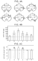
- each cardiac potential was measured by using the right and left electrodes against the neck part N in various arrangements A to F in the longitudinal direction of the band member 2, as shown in FIG. 4A ; and magnitudes of the amplitudes as defined in FIG. 2A in measurement data and corresponding heart rates detected in the measurement data were results as respectively shown in FIG. 4B and FIG. 4C .
- These results indicate respective average values (bar graphs) and respective standard deviations (error bars) obtained from the measurement data for 30 seconds from three examinees.
- An electrode having a flat contact surface of 5 mm x 5 mm was used as each electrode.
- Each of chain lines in the drawings indicates a lower limit of an acceptable value for each detected value in each vertical axis.
- each average value and each standard deviation are more than the respective acceptable values in the arrangements B, C, and D in FIG. 4A , that is, in the arrangement where the electrode 4a located on the right of the examinee was located relatively more frontward than the position of the electrode 4b on the left of the examinee.
- the respective measurement values of both the amplitude and the heart rate become the maximum.
- the bio-information detecting apparatus 1 of the present invention it is possible to improve the measurement sensitivity of the cardiac potential by arranging the electrode located on the right of the examinee to be relatively more frontward than the position of the electrode located on the left of the examinee, more preferably, by arranging the electrode on the right of the examinee to be relatively more frontward than the lateral side of the neck part of the examinee, and also arranging the electrode on the left of the examinee to be relatively more backward than the lateral side of the neck part of the examinee.
- the cardiac potential measurement is carried out with a method called as a 12-lead electrocardiography that measures cardiac potential by arranging electrodes on hands and feet of a human body with a heart surrounded by these electrodes.
- the measurement is carried out by arranging the electrodes at the positions on the neck part where the heart is not surrounded by these electrodes. Accordingly, the present invention reveals, for the first time, the configuration capable of carrying out the cardiac potential measurement with high measurement sensitivity by arranging the pair of electrodes at positions that do not surround the heart.
- the bio-information detecting apparatus 1 that is the subject matter of the present invention is a portable apparatus attached to the neck part of the examinee; therefore, it is preferable to stably maintain each contact of the electrodes for the cardiac potential measurement with the skin surface of the examinee regardless of body motions and postures of the examinee so as to measure the cardiac potential in a preferable manner.
- it can be expected to stabilize the contact of each electrode with the skin surface by configuring the contact surface of each electrode to have a center portion protruding toward the skin surface more than a peripheral edge of the contact surface.
- the inventors of the present invention have studied on this point, and have found that if the protrusion of the contact surface of each electrode (in a direction toward the skin surface) is as great as 2 mm, the measurement sensitivity to the cardiac potential greatly decreases.
- the contact surface of each electrode since the bio-information detecting apparatus 1 as the subject matter of the present invention is attached around the neck part of the examinee, it is preferable to define the contact surface of each electrode to be as small as possible because a larger contact surface of each electrode causes a greater inconvenience to movement of the neck of the examinee.
- an electrode formed to have a contact surface of which protrusion is not more than 1 mm, and of which contact area is not less than 25 mm 2 as each electrode so as to prevent the measurement sensitivity of the measurement data of the cardiac potential from becoming less than the acceptable level.
- the bio-information detecting apparatus 1 may include only at least one of the pulse measurement unit and the pair of electrodes for the cardiac potential measurement.
- the bio-information detecting apparatus 1 of the present invention may be attached around a neck part of a vehicle driver so as to be used for measuring the heartbeats and the pulse of the driver during vehicle driving.
Landscapes
- Health & Medical Sciences (AREA)
- Life Sciences & Earth Sciences (AREA)
- Physics & Mathematics (AREA)
- Surgery (AREA)
- General Health & Medical Sciences (AREA)
- Engineering & Computer Science (AREA)
- Biomedical Technology (AREA)
- Heart & Thoracic Surgery (AREA)
- Medical Informatics (AREA)
- Molecular Biology (AREA)
- Biophysics (AREA)
- Animal Behavior & Ethology (AREA)
- Pathology (AREA)
- Public Health (AREA)
- Veterinary Medicine (AREA)
- Cardiology (AREA)
- Spectroscopy & Molecular Physics (AREA)
- Optics & Photonics (AREA)
- Physiology (AREA)
- Pulmonology (AREA)
- Measuring Pulse, Heart Rate, Blood Pressure Or Blood Flow (AREA)
- Measurement And Recording Of Electrical Phenomena And Electrical Characteristics Of The Living Body (AREA)
- Measurement Of The Respiration, Hearing Ability, Form, And Blood Characteristics Of Living Organisms (AREA)
Abstract


Description
- The present invention relates to an apparatus to measure bio-information. Particularly, the present invention relates to an apparatus to measure bio-information regarding human heartbeats, such as cardiac potential and pulse waves, and more specifically, to a neck-band type bio-information detecting apparatus attached (or worn) around a human neck part.
- There have been developed techniques of promoting reduction in dimension of sensors capable of measuring bio-information regarding human heartbeats, such as cardiac potential and pulse waves, and transmitting measurement values of these sensors via radio communication. Therefore, there have been proposed various portable bio-information detecting apparatuses attached to heads, necks, or the like of examinees so as to allow the examinees to relatively freely take exercise. For example, in Japanese Patent Application Publication No.
2003-325466 2007-202939 2015-73557 - One of the current challenges in bio-information detecting apparatuses including measurement means to measure cardiac potential and pulse waves on neck bands attached around neck parts is to measure cardiac potential and blood oxygen saturation with as high measurement sensitivity as possible. For example, if cardiac potential is measured at a neck part, its measurement part is located apart from a heart; thus measurement sensitivity becomes considerably deteriorated compared with the case of measuring cardiac potential at a chest part near the heart. Actually, cardiac potential measuring means of a type that has electrodes at both ends of a neck band detects considerably smaller amplitudes of measurement values of cardiac potential. When a neck band is attached around a neck part, elasticity of the neck band is utilized so as to prevent the neck band from dropping off the neck. However, depending on the degree of pressure onto a vessel with too strong elasticity, it is confirmed that some influence might be caused to amplitudes of measurement values of pulse waves (blood oxygen saturation). Hence, in above described neck-band type bio-information detecting apparatuses attached around neck parts, it is preferable to improve configurations thereof in order to improve measurement sensitivity of cardiac potential and pulse waves.
- Accordingly, one aim of the present invention is to provide a novel configuration to improve sensitivity of measurement values of cardiac potential and blood oxygen saturation in a bio-information detecting apparatus having measurement means of cardiac potential and pulse waves in a neck band attached around a neck part.
- According to one aspect of the present invention, there is provided is a bio-information detecting apparatus, including: a band member curved in a C-shape, the band member attached in a manner as to extend along a neck part of an examinee from a back side of the neck part toward both lateral sides of the neck part; and a pair of electrodes for cardiac potential measurement of the examinee, the pair of electrodes disposed at positions of the band member that come into contact with right and left skin surfaces of the neck part of the examinee, wherein, of the pair of electrodes, a position of the electrode located on the right of the examinee is located relatively more frontward than a position of the electrode located on the left of the examinee. In the above configuration, as is easily understood with reference to drawings of embodiments described later, the "band member curved in a C-shape" denotes a member having a neck band structure attached from the back side of the neck part of the examinee, and typically is formed by a flexible or elastic material, such as a plastic material that has been commonly used in this field. The "pair of electrodes for cardiac potential measurement" may be electrode pieces commonly used in this field, and each of the electrodes has a dimension of approximately several mm to 2 cm large enough for measuring the cardiac potential.
- As aforementioned, in the bio-information detecting apparatus of the present invention, the "pair of electrodes for cardiac potential measurement" is arranged on the "band member" in a manner as to be in contact with the right and left skin surfaces of the neck part of the examinee, and the positions of the electrodes are arranged in such a manner that the electrode located on the right of the examinee is disposed relatively more frontward than the position of the electrode located on the left of the examinee. As described later, if the pair of electrodes are arranged on the band member, various configurations of electrode arrangement along the band member may be considered; and according to experiments conducted by the inventors of the present invention, it has been found that if the electrode on the right is disposed more frontward than the electrode on the left, the amplitude of the measured cardiac potential becomes considerably greater than that in the other cases, thereby measuring the cardiac potential in a preferable manner. In the apparatus of the present invention, as aforementioned, the electrode located on the right of the examinee is disposed relatively more frontward than the position of the electrode located on the left of the examinee, thereby increasing the measurement sensitivity of the cardiac potential. It has also been found that if the electrode located on the right is disposed in a more frontward region on the band member than the right lateral side of the neck part of the examinee, and the electrode located on the left is disposed at a more backward position on the band member than the left lateral side of the neck part of the examinee, the amplitude of the measured cardiac potential becomes the maximum. Hence, more preferably, in the apparatus of the invention, as aforementioned, the electrode on the right may be disposed in a more frontward region on the band member than the right lateral side of the neck part of the examinee, and the electrode on the left may be disposed at a more backward position on the band member than the left lateral side of the neck part of the examinee.
- In the above electrodes, it may be configured that each contact surface of the pair of electrodes that comes into contact with the skin surface of the neck part of the examinee is in a flat state or in a curved state in a direction in which a center portion of the contact surface protrudes more than a peripheral edge of the contact surface toward the skin surface of the neck part of the examinee, the protrusion being within a range of not more than 1 mm. With respect to the contact surface of each electrode, in order to bring each electrode to stably contact with the neck part of the examinee, for example, it is considered to be preferable that the contact surface of each electrode with the skin surface of the neck part of the examinee is formed to be curved such that the center portion of the contact surface protrudes more than the peripheral edge thereof toward the skin surface of the neck part of the examinee so as to securely contact with the skin surface of the neck part. According to the experiments, it has been found that the amplitude of the measured cardiac potential is detected with the most excellent sensitivity, and if the center portion of the contact surface protrudes more than the peripheral edge thereof by more than 1 mm toward the skin surface of the neck part of the examinee, the amplitude of the measured cardiac potential becomes significantly decreased compared with the case of the contact surface having a flat shape. In the present invention, preferably, it may be configured that the contact surface of each electrode that comes into contact with the skin surface of the neck part of the examinee is in a flat state or in a curved state in a direction in which a center portion of the contact surface protrudes more than a peripheral edge thereof toward the skin surface of the neck part of the examinee, the protrusion being within a range of not more than 1 mm.
- Furthermore, with respect to the aforementioned electrodes, according to the experiments, it has been found that if the contact area of each electrode with the skin surface of the neck part of the examinee is less than 25 mm2, the measurement sensitivity to the amplitude of the cardiac potential becomes significantly decreased. Hence, in the above described present invention, preferably, a contact area of each of the pair of electrodes that comes into contact with the skin surface of the neck part of the examinee may be more than 25 mm2.
- According to another aspect of the present invention, there is provided a bio-information detecting apparatus including: a band member curved in a C-shape, the band member attached in a manner as to extend along a neck part from a back side of the neck part toward both lateral sides of the neck part to a region more frontward than the lateral side of the neck part; and a substrate disposed at a position on the band member that comes into contact with the neck part of the examinee, the substrate having a light emitting part and a light receiving part that are used for optically measuring a blood oxygen saturation for pulse measurement of the examinee, wherein in a state in which the substrate is in contact with a skin surface of the neck part of the examinee, a pressing force of the substrate against the skin surface of the neck part is 0.96 to 1.21[N/cm2]. The "substrate having a light emitting part and a light receiving part used for optically measuring blood oxygen saturation for pulse measurement" may be any sensor unit optically measuring the blood oxygen saturation in this field, as described in
JP 2007-202939 A - The configuration of setting the pressing force of the substrate for the pulse measurement to be within a range of 0.96 to 1.21[N/cm2] may be applicable to the bio-information detecting apparatus including the configuration regarding the aforementioned electrodes for the cardiac potential measurement. According to this configuration, it is possible to hold the apparatus having the band-like structure curved in a C-shape against the neck part in a manner as not to be out of position by the electrodes and the substrate, thereby measuring both the cardiac potential and the pulse with an excellent sensitivity, which results in advantage.
- As aforementioned, in the configuration of the above described present invention, it is possible to measure cardiac potential and pulse pertinent to human heartbeats with a more excellent sensitivity through the neck-band type apparatus attached around a human neck part, compared with the conventional configuration. The neck-band type apparatus attached around a human neck part is portable and allows measurement at portions of an examinee regardless of accessories and clothes, which results in advantage. According to the present invention, it is expected to improve measurement accuracy of cardiac potential and pulse in a neck-band type bio-information detecting apparatus as above configured, and it is also expected to facilitate measurement of cardiac potential and pulse more than the conventional one, and promote increase in opportunity to use the apparatus.
- The other objects and advantages of the present invention will be revealed by the following description of preferable embodiments of the present invention.
- Features, advantages, and technical and industrial significance of exemplary embodiments of the invention will be described below with reference to the accompanying drawings, in which like numerals denote like elements, and wherein:
-
FIG. 1A is a schematic perspective view of a bio-information detecting apparatus of the present invention; -
FIG. 1B is a schematic perspective view of the bio-information detecting apparatus of the present invention in a state of being attached around a neck part of an examinee; -
FIG. 1C is a schematic plan view of the bio-information detecting apparatus of the present invention; -
FIG. 1D is a drawing illustrating an internal configuration of a signal flow of the bio-information detecting apparatus of the present invention in a block diagram; -
FIG. 2A shows an example of measurement data of cardiac potential measured by a pair of electrodes for cardiac potential measurement in the bio-information detecting apparatus of the present invention; -
FIG. 2B shows an example of measurement data of an optical blood saturation measurement unit for pulse wave measurement in the bio-information detecting apparatus of the present invention; -
FIG. 3A shows a schematic side view showing a state in which the optical blood saturation measurement unit for pulse wave measurement in the bio-information detecting apparatus is pushed against a skin surface of a neck part of an examinee; -
FIG. 3B is a schematic plan view showing the state in which the optical blood saturation measurement unit for pulse wave measurement in the bio-information detecting apparatus is pushed against the skin surface of the neck part of the examinee; -
FIG. 3C shows respective pressure pressing forces of the optical blood saturation measurement unit for pulse wave measurement against the skin surface of the neck part and change in amplitude of measured pulse waves (blood saturation); -
FIG. 4A is a drawing schematically showing various arrangement examples of the pair of electrodes for cardiac potential measurement in the bio-information detecting apparatus; -
FIG. 4B shows respective amplitudes of the cardiac potential obtained by attaching the electrodes in the respective arrangement examples ofFIG. 4A to the examinee; -
FIG. 4C shows respective heart rates detected by attaching the electrodes in the various arrangement examples ofFIG. 4A to the examinee; -
FIG. 5A is a drawing showing respective sectional shapes of contact surfaces in contact with the skin surface of the neck part of the examinee of each electrode for cardiac potential measurement in the bio-information detecting apparatus, and corresponding cardiac potential measurement examples; -
FIG. 5B shows change in amplitude of the cardiac potential measured depending on respective amounts of protrusion of a center portion relative to a peripheral edge of the contact surface of each electrode; and -
FIG. 5C shows change in amplitude of the cardiac potential measured depending on the respective areas of the contact surfaces of the electrode. - Several preferable embodiments of the present invention will be described with reference to accompanying drawings, hereinafter. In the following drawings, the same reference numerals indicate the same parts.
- With reference to
FIG. 1A , abio-information detecting apparatus 1 of the present invention includes, as a basic configuration thereof, aband member 2 curved in a substantially C-shape, and a pair ofelectrodes band member 2, and an optical bloodsaturation measurement unit 5 for pulse wave measurement (referred to as a "pulse measurement unit", hereinafter). Asignal processing unit 3 receives potential differences between theelectrode 4a and theelectrode 4b, and measurement values (light intensity received by a light receiving part as described later) of thepulse measurement unit 5, and includes a radio transmitting unit that transmits the above data to any external processing unit, and thissignal processing unit 3 is fixed to the vicinity of the center portion of the C-shapedband member 2. Theband member 2 may typically be formed by a flexible or elastic material, such as a plastic material or a resin material, or such as a plastic material or a resin material containing a metallic band-like member thereinside. The pair ofelectrodes pulse measurement unit 5 may be any (reflecting-type) optical pulse measurement device (substrate including a light emitting part and the light receiving part) used in this field. Thebio-information detecting apparatus 1 is a so-called neck-band type apparatus, and is configured, as schematically illustrated inFIG. 1B and FIG. 1C , such that theband member 2 to which thesignal processing unit 3 is fixed is attached in such a manner that a center region of the C-shape of theband member 2 is disposed to a back side of a neck part N of an examinee, and theband member 2 extends along and surrounds the neck part N so that both ends of the C-shape reach respective positions more frontward than both lateral sides (or lateral mid points) Sl, Sr of the neck part N of the examinee. On theband member 2, the pair ofelectrodes bio-information detecting apparatus 1 is attached (or worn) around the neck part N. Thepulse measurement unit 5 is arranged with a measurement surface (the light emitting part and the light receiving part) thereof in contact with the skin surface of the neck part N in the state in which thebio-information detecting apparatus 1 is attached around the neck part N. Thesignal processing unit 3 includes, more specifically, asignal processing substrate 3b that receives and processes signals from the pair ofelectrodes pulse measurement unit 5, and abattery 3a used for driving theelectrodes pulse measurement unit 5, and thesignal processing substrate 3b. - The configuration of signal processing in the cardiac potential measurement and the optical pulse measurement in the
bio-information detecting apparatus 1 of the aforementioned neck-band type may be any signal processing for cardiac potential measurement and pulse wave measurement. Briefly stated, as shown inFIG. 1D , the cardiac potential measurement is processed in such a manner that the potential difference between the pair ofelectrodes FIG. 2A . Meanwhile, in the optical pulse measurement, a light having a wavelength bandwidth to be absorbed into hemoglobin combined with oxygen in an arterial blood from the light emitting part provided on the measurement surface of thepulse measurement unit 5 in contact with the skin surface of the neck part N of the examinee is radiated onto a surface layer of the skin. In the above radiated light, a light reflected onto the surface layer of the skin without being absorbed into the hemoglobin combined with oxygen in the arterial blood is received by the light receiving part (also referred to as a reflecting-type pulse oxymeter). Signals indicating the light intensity of the light received by the light receiving part are successively sent to the amplifier to be amplified, digitalized by the AD converter, and is then processed in the signal processing unit to be sent to any external processing apparatus. As is well known in this field, the light intensity received by the light receiving part is proportional to amount of hemoglobin combined with oxygen in blood (oxygen saturation), and the amount of bloodstream hemoglobin becomes increased or decreased in accordance with the pulse. Hence, the light intensity received by the light receiving part oscillates, and these oscillations are correspondent to the pulse, as exemplified inFIG. 2B . Accordingly, the signals indicating the cardiac potential and the signals indicating the pulse are respectively transmitted from the radio communicating unit to any external processing apparatus. - As described above, in the cardiac potential measurement and the optical pulse measurement of the
bio-information detecting apparatus 1 attached around the neck part of the examinee in the aforementioned manner, one of the challenges to be achieved is how to improve the measurement sensitivity of the cardiac potential and the pulse (oxygen saturation). In the successive cardiac potential data and pulse wave data as exemplified inFIG. 2A and FIG. 2B , as illustrated in these drawings, amplitudes of the oscillating waveforms are measured, occurrence of the oscillations, that is, occurrence of the heartbeats or the pulse is successively detected, and then the heart rate and the pulse rate are measured. With respect to this, in the cardiac potential measurement, the cardiac potential, which has conventionally been measured at a chest part near the heart, is instead measured at the neck part further away from the heart, and thus the amplitude of the cardiac potential is decreased more than that in the case of measurement at the chest part near the heart. In the pulse measurement, change in blood flow rate in the artery is measured, but if the blood is pooled (or restrained) in the vessel, the blood flow rate decreases, and thus the amplitude of the pulse (oxygen saturation) becomes decreased. In particular, because thebio-information detecting apparatus 1 is supposed to be attached around the neck part of the examinee, it is necessary to stably maintain the contact state of the electrodes and the pulse measurement unit with the skin surface even if the body of the examinee moves to some extent. - To cope with this, the inventors of the present invention have conducted various studies, and as a result, they have found a novel configuration capable of increasing measurement sensitivity of the cardiac potential and the pulse, in particular, the respective amplitudes of the cardiac potential and the pulse. Hereinafter, the novel configuration in the
bio-information detecting apparatus 1 according to the present invention will be described. - The aforementioned
bio-information detecting apparatus 1 is positioned in a stable manner with an elastic force F (applied in a direction vertical to an extending direction of the neck part) of theband member 2 when thebio-information detecting apparatus 1 is attached around the neck part N of the examinee, as schematically illustratedFIG. 3A . In such a configuration, thepulse measurement unit 5 and the pair ofelectrodes band member 2 are pressed against the skin surface of the neck part N, as schematically illustrated inFIG. 3B . At this time, particularly in the pulse measurement, an excessively strong pressing force P causes reduction in blood flow rate due to pooled blood in the vessel, as aforementioned, and thus the measured sensitivity (magnitude of the amplitude of the pulse) becomes decreased. In addition, if the pressing force P is excessively weak, theband member 2 is likely to move, or thepulse measurement unit 5 is likely to be out of contact with the skin surface, and thus the measurement sensitivity also becomes decreased. To cope with this difficulty, studies have been carried out to determine a preferable range of the pressing force to press thepulse measurement unit 5 against the skin surface in which a measurement value of thepulse measurement unit 5 falls within an acceptable range. - The
bio-information detecting apparatus 1 usingplural band members 2 with different elastic forces F was attached to the examinee so as to variously change the pressing force P of thepulse measurement unit 5 against the skin surface, and measure the pulse depending on the various pressing forces P by using thepulse measurement unit 5. As a result, change in amplitude (defined inFIG. 2B ) obtained from the measurement data of the pulse depending on the various pressing forces exhibits a result as shown inFIG. 3C . In the drawing, each point "◆" represents a data plot, and a chain line represents a lower limit value of the acceptable amplitude. - As is understood with reference to this drawing, if the pressing force falls within a range of 0.96 to 1.21[N/cm2], the amplitude becomes an acceptable value, and in particular, the amplitude becomes the maximum with the pressing force in the vicinity of 1.1[N/cm2]. This pressing force is equivalent to a force to push down the skin surface by approximately 1 mm.
- As described above, in the
bio-information detecting apparatus 1 of the present invention, the dimension of theband member 2 is so defined as to apply the elastic force F of theband member 2 causing the pressing force of thepulse measurement unit 5 against the skin surface of the neck part that falls within a range of 0.96 to 1.21[N/cm2], more preferably, within a range of approximately 1.1[N/cm2], thereby improving the sensitivity of the pulse measurement. A significant pressing force within the above range is applied from thepulse measurement unit 5 onto the neck part so that the apparatus having the band-like structure curved in a C-shape can be held relative to the neck part while preventing the apparatus from being out of position, which attains another advantage (it has been confirmed that the cardiac potential can be measured within the above pressing-force range if the following conditions of the configuration regarding the electrodes are satisfied). - Based on the studies conducted by the inventors of the present invention, it has been found that the amplitude of measured cardiac potential is greatly affected by the arrangement of the pair of electrodes for cardiac potential measurement in a direction along the C-shape of the band member 2 (longitudinal direction of the band member 2), and in particular, if the electrode located on the right of the examinee is disposed relatively more frontward than the position of the electrode located on the left of the examinee, the cardiac potential amplitude becomes greatly increased compared with that in the other cases.
- With reference to
FIGS. 4 , each cardiac potential was measured by using the right and left electrodes against the neck part N in various arrangements A to F in the longitudinal direction of theband member 2, as shown inFIG. 4A ; and magnitudes of the amplitudes as defined inFIG. 2A in measurement data and corresponding heart rates detected in the measurement data were results as respectively shown inFIG. 4B and FIG. 4C . These results indicate respective average values (bar graphs) and respective standard deviations (error bars) obtained from the measurement data for 30 seconds from three examinees. An electrode having a flat contact surface of 5 mm x 5 mm was used as each electrode. Each of chain lines in the drawings indicates a lower limit of an acceptable value for each detected value in each vertical axis. - As is understood with reference to the results in the
FIG. 4B and FIG. 4C , with respect to both the amplitude and the heart rate, each average value and each standard deviation are more than the respective acceptable values in the arrangements B, C, and D inFIG. 4A , that is, in the arrangement where theelectrode 4a located on the right of the examinee was located relatively more frontward than the position of theelectrode 4b on the left of the examinee. In particular, in the arrangement in which theright electrode 4a was located in a more frontward region than the lateral side of the neck part of the examinee, and in the arrangement in which theleft electrode 4b was located more backward than the lateral side of the neck part of the examinee, the respective measurement values of both the amplitude and the heart rate become the maximum. In thebio-information detecting apparatus 1 of the present invention, it is possible to improve the measurement sensitivity of the cardiac potential by arranging the electrode located on the right of the examinee to be relatively more frontward than the position of the electrode located on the left of the examinee, more preferably, by arranging the electrode on the right of the examinee to be relatively more frontward than the lateral side of the neck part of the examinee, and also arranging the electrode on the left of the examinee to be relatively more backward than the lateral side of the neck part of the examinee. In general, the cardiac potential measurement is carried out with a method called as a 12-lead electrocardiography that measures cardiac potential by arranging electrodes on hands and feet of a human body with a heart surrounded by these electrodes. However, according to the present invention, the measurement is carried out by arranging the electrodes at the positions on the neck part where the heart is not surrounded by these electrodes. Accordingly, the present invention reveals, for the first time, the configuration capable of carrying out the cardiac potential measurement with high measurement sensitivity by arranging the pair of electrodes at positions that do not surround the heart. - As aforementioned, the
bio-information detecting apparatus 1 that is the subject matter of the present invention is a portable apparatus attached to the neck part of the examinee; therefore, it is preferable to stably maintain each contact of the electrodes for the cardiac potential measurement with the skin surface of the examinee regardless of body motions and postures of the examinee so as to measure the cardiac potential in a preferable manner. With respect to this point, as a solution for stably maintaining the contact state of each electrode with the skin surface, it can be expected to stabilize the contact of each electrode with the skin surface by configuring the contact surface of each electrode to have a center portion protruding toward the skin surface more than a peripheral edge of the contact surface. The inventors of the present invention have studied on this point, and have found that if the protrusion of the contact surface of each electrode (in a direction toward the skin surface) is as great as 2 mm, the measurement sensitivity to the cardiac potential greatly decreases. With respect to the dimension of the contact surface of each electrode, since thebio-information detecting apparatus 1 as the subject matter of the present invention is attached around the neck part of the examinee, it is preferable to define the contact surface of each electrode to be as small as possible because a larger contact surface of each electrode causes a greater inconvenience to movement of the neck of the examinee. On the contrary, if each electrode has an excessively small dimension, and the contact area between the electrode and the skin surface becomes excessively small, it becomes difficult to measure the potential difference between the electrodes with a preferable sensitivity. To cope with this difficulty, studies have been conducted on an upper limit of the protrusion of the contact surface and a lower limit of the contact area in each electrode where acceptable measurement data of the cardiac potential can be obtained. - With respect to change in magnitude of the amplitude in the measurement data depending on the various protrusions of the contact surface of each electrode, as shown in
FIG. 5B , it has been found that the amplitude becomes less than the acceptable level if the protrusion becomes more than 1 mm (an electrode of 5 mm x 5 mm was used as each electrode). With respect to change in magnitude of the amplitude in the measurement data depending on the various contact areas of the contact surface of each electrode, as shown inFIG. 5C , it has been found that the amplitude of the cardiac potential becomes significantly decreased if the contact area of each electrode with the skin surface of the neck part of the examinee becomes less than 25 mm2 (an electrode having a flat contact surface was used as each electrode). Accordingly, in thebio-information detecting apparatus 1 of the present invention, there is employed an electrode formed to have a contact surface of which protrusion is not more than 1 mm, and of which contact area is not less than 25 mm2 as each electrode so as to prevent the measurement sensitivity of the measurement data of the cardiac potential from becoming less than the acceptable level. - In the present embodiment, it should be appreciated that the
bio-information detecting apparatus 1 may include only at least one of the pulse measurement unit and the pair of electrodes for the cardiac potential measurement. Thebio-information detecting apparatus 1 of the present invention may be attached around a neck part of a vehicle driver so as to be used for measuring the heartbeats and the pulse of the driver during vehicle driving. - Although the above explanation has been made with respect to the embodiments of the present invention, it will be apparent for those skilled in the art that various modifications and changes are possible, and that the present invention is not limited to the above-illustrated embodiments, and may be applied to various devices and apparatuses without departing from the concepts of the present invention.
Claims (8)
- A bio-information detecting apparatus characterized by comprising:a band member (2) curved in a C-shape, the band member (2) wearable by an examinee to extend around a neck part of the examinee from a back side of the neck part toward both lateral sides of the neck part; anda pair of electrodes (4a, 4b) for cardiac potential measurement of the examinee, the pair of electrodes (4a, 4b) being disposed at respective positions on the left and right side of the band member (2) so as to come into contact with right and left skin surfaces of the neck part of the examinee,whereinof the pair of electrodes (4a, 4b), the electrode located on the right of the examinee is located relatively more frontward than a position of the electrode located on the left of the examinee.
- The bio-information detecting apparatus according to claim 1, wherein
the electrode on the right is disposed in a more frontward region on the band member (2) than the right lateral mid point (Sr)of the neck part of the examinee, and
the electrode on the left is disposed at a more backward position on the band member (2) than the left lateral mid point (Sl) of the neck part of the examinee. - The bio-information detecting apparatus according to claim 1 or 2, further comprising
a substrate having a light emitting part and a light receiving part, each of which is configured to optically measure a blood oxygen saturation for pulse measurement of the examinee, the substrate disposed at a position on the band member (2) that comes into contact with the neck part of the examinee,
and
in a state in which the substrate is in contact with a skin surface of the neck part of the examinee, a pressing force of the substrate against the skin surface of the neck part is 0.96 to 1.21 N/cm2. - The bio-information detecting apparatus according to any one of claims 1 to 3,
wherein
the contact surface of each of the pair of electrodes (4a, 4b) that comes into contact with the skin surface of the neck part of the examinee is in a flat state or in a curved state in a direction in which a center portion of the contact surface protrudes beyond a peripheral edge of the contact surface toward the skin surface of the neck part of the examinee, the protrusion being not more than 1 mm. - The bio-information detecting apparatus according to any one of claims 1 to 4,
wherein
a contact area of each of the pair of electrodes (4a, 4b) that comes into contact with the skin surface of the neck part of the examinee is more than 25 mm2. - A bio-information detecting apparatus characterized by comprising:a band member (2) curved in a C-shape, the band member (2) wearable by an examinee to extend around a neck part of the examinee from a back side of the neck part toward both lateral sides of the neck part to a region more frontward than the lateral side of the neck part; anda substrate disposed at a position on the band member (2) that comes into contact with the neck part of the examinee, the substrate having a light emitting part and a light receiving part that are used for optically measuring a blood oxygen saturation for pulse measurement of the examinee,whereinin a state in which the substrate is in contact with a skin surface of the neck part of the examinee, a pressing force of the substrate against the skin surface of the neck part is 0.96 to 1.21 N/cm2.
- The bio-information detecting apparatus of any preceding claim, wherein the bio-information detecting apparatus is attached to an examinee.
- A method of using the bio-information detecting apparatus of any of claims 1-6 comprising attaching the band member to an examinee such that the electrode disposed on the left side of the band member is in contact with the left skin surface of the neck part of the examinee, and the right side of the band member is in contact with the right skin surface of the neck part of the examinee.
Applications Claiming Priority (1)
| Application Number | Priority Date | Filing Date | Title |
|---|---|---|---|
| JP2015172614A JP6524867B2 (en) | 2015-09-02 | 2015-09-02 | Neck band type biological information detector |
Publications (2)
| Publication Number | Publication Date |
|---|---|
| EP3138483A1 true EP3138483A1 (en) | 2017-03-08 |
| EP3138483B1 EP3138483B1 (en) | 2020-09-23 |
Family
ID=56852156
Family Applications (1)
| Application Number | Title | Priority Date | Filing Date |
|---|---|---|---|
| EP16186664.5A Not-in-force EP3138483B1 (en) | 2015-09-02 | 2016-08-31 | Bio-information detecting method |
Country Status (5)
| Country | Link |
|---|---|
| US (1) | US10405798B2 (en) |
| EP (1) | EP3138483B1 (en) |
| JP (1) | JP6524867B2 (en) |
| KR (1) | KR101837592B1 (en) |
| CN (1) | CN106473718B (en) |
Families Citing this family (10)
| Publication number | Priority date | Publication date | Assignee | Title |
|---|---|---|---|---|
| JP6729704B2 (en) * | 2016-09-02 | 2020-07-22 | 株式会社村田製作所 | Blood pressure estimation device |
| JP2021013404A (en) * | 2017-11-01 | 2021-02-12 | アルプスアルパイン株式会社 | Biometric information measuring device, information processing device, biometric information measuring method, and program |
| KR102146953B1 (en) | 2019-01-04 | 2020-08-21 | 주식회사 엠트리케어 | Blood flow and blood vessel measuring apparatus |
| CA3128867A1 (en) * | 2019-01-31 | 2020-08-06 | Flow Cpr Inc. | Apparatus and method for calculating a volume flow rate of oxygenated blood |
| KR102215276B1 (en) | 2019-03-08 | 2021-02-15 | 주식회사 힐세리온 | Wireless blood flow and blood vessel measuring apparatus |
| JP1662391S (en) * | 2019-11-21 | 2020-06-29 | ||
| US11045622B1 (en) * | 2020-06-12 | 2021-06-29 | James M. Johnson | Shoulder-worn diffuser |
| KR102493264B1 (en) * | 2020-06-23 | 2023-01-30 | 한양대학교 산학협력단 | Wearable device and method for measuring multi bio signal |
| GB2602158B (en) * | 2020-12-21 | 2025-03-12 | Nordiq Products As | Vital signs monitoring device |
| CN117122332A (en) * | 2023-07-18 | 2023-11-28 | 未来穿戴健康科技股份有限公司 | ECG monitor |
Citations (7)
| Publication number | Priority date | Publication date | Assignee | Title |
|---|---|---|---|---|
| FR2748928A1 (en) * | 1996-05-23 | 1997-11-28 | Jabourian Artin Pascal | Portable electronic cardiac rhythm detector |
| JP2003325466A (en) | 2002-05-14 | 2003-11-18 | Omron Corp | Heart rate measurement device |
| JP2007202939A (en) | 2006-02-06 | 2007-08-16 | Masafumi Matsumura | Biological information detecting apparatus |
| US20100137726A1 (en) * | 2006-12-25 | 2010-06-03 | Masafumi Matsumura | Electrode device and electrocardiographic measurement device |
| US20140236031A1 (en) * | 2013-02-20 | 2014-08-21 | Perminova Inc. | Necklace-shaped physiological monitor |
| JP2015073557A (en) | 2013-10-04 | 2015-04-20 | 日本光電工業株式会社 | Sensor and fixture |
| US20150148618A1 (en) * | 2013-09-27 | 2015-05-28 | Krzysztof Sitko | Physiological Monitor and Methods for Placement and Wear |
Family Cites Families (11)
| Publication number | Priority date | Publication date | Assignee | Title |
|---|---|---|---|---|
| JPS6015303U (en) * | 1983-07-08 | 1985-02-01 | スタンレー電気株式会社 | blood flow detector |
| US4859057A (en) * | 1987-10-13 | 1989-08-22 | Lawrence Medical Systems, Inc. | Oximeter apparatus |
| JPH09108191A (en) * | 1995-10-20 | 1997-04-28 | Seiko Epson Corp | Pulse wave measuring device |
| US6690959B2 (en) * | 2000-09-01 | 2004-02-10 | Medtronic, Inc. | Skin-mounted electrodes with nano spikes |
| AT413638B (en) * | 2001-03-13 | 2006-04-15 | Cnsystems Medizintechnik Gmbh | MEDICAL ELECTRODE |
| US20050228242A1 (en) * | 2004-04-08 | 2005-10-13 | Tatsurou Kawamura | Health management system |
| JP2008161657A (en) * | 2006-12-05 | 2008-07-17 | Masafumi Matsumura | Method and device for monitoring unrestraint life rhythm |
| JP5487496B2 (en) * | 2009-07-09 | 2014-05-07 | 国立大学法人大阪大学 | Bioelectric signal measurement device |
| JP5706539B2 (en) * | 2011-11-17 | 2015-04-22 | 日本電信電話株式会社 | Conductive polymer fiber, biological electrode, implantable electrode, and biological signal measuring device |
| JP6267654B2 (en) * | 2012-02-08 | 2018-01-24 | イージージー エルエルシー | ECG system with multi-mode electrode unit |
| JP2016015978A (en) | 2014-07-04 | 2016-02-01 | セイコーエプソン株式会社 | Biological information detection device |
-
2015
- 2015-09-02 JP JP2015172614A patent/JP6524867B2/en not_active Expired - Fee Related
-
2016
- 2016-08-30 KR KR1020160110787A patent/KR101837592B1/en not_active Expired - Fee Related
- 2016-08-31 EP EP16186664.5A patent/EP3138483B1/en not_active Not-in-force
- 2016-08-31 CN CN201610794560.8A patent/CN106473718B/en not_active Expired - Fee Related
- 2016-09-01 US US15/254,691 patent/US10405798B2/en not_active Expired - Fee Related
Patent Citations (7)
| Publication number | Priority date | Publication date | Assignee | Title |
|---|---|---|---|---|
| FR2748928A1 (en) * | 1996-05-23 | 1997-11-28 | Jabourian Artin Pascal | Portable electronic cardiac rhythm detector |
| JP2003325466A (en) | 2002-05-14 | 2003-11-18 | Omron Corp | Heart rate measurement device |
| JP2007202939A (en) | 2006-02-06 | 2007-08-16 | Masafumi Matsumura | Biological information detecting apparatus |
| US20100137726A1 (en) * | 2006-12-25 | 2010-06-03 | Masafumi Matsumura | Electrode device and electrocardiographic measurement device |
| US20140236031A1 (en) * | 2013-02-20 | 2014-08-21 | Perminova Inc. | Necklace-shaped physiological monitor |
| US20150148618A1 (en) * | 2013-09-27 | 2015-05-28 | Krzysztof Sitko | Physiological Monitor and Methods for Placement and Wear |
| JP2015073557A (en) | 2013-10-04 | 2015-04-20 | 日本光電工業株式会社 | Sensor and fixture |
Also Published As
| Publication number | Publication date |
|---|---|
| CN106473718A (en) | 2017-03-08 |
| KR20170027664A (en) | 2017-03-10 |
| JP2017046927A (en) | 2017-03-09 |
| US20170055904A1 (en) | 2017-03-02 |
| KR101837592B1 (en) | 2018-03-12 |
| EP3138483B1 (en) | 2020-09-23 |
| JP6524867B2 (en) | 2019-06-05 |
| US10405798B2 (en) | 2019-09-10 |
| CN106473718B (en) | 2019-11-01 |
Similar Documents
| Publication | Publication Date | Title |
|---|---|---|
| US10405798B2 (en) | Bio-information detecting apparatus | |
| US12446786B2 (en) | Pulse wave transit time measurement device and living body state estimation device | |
| JP6620821B2 (en) | Fatigue detection device | |
| US20210251501A1 (en) | Body-worn pulse oximeter | |
| JP6583427B2 (en) | Pulse wave propagation time measurement device and biological state estimation device | |
| JP6308294B2 (en) | Pulse wave propagation time measurement device and biological state estimation device | |
| US11369276B2 (en) | Blood pressure measurement device | |
| JP6569509B2 (en) | Biological signal detection device | |
| US12171530B2 (en) | Pulse transit time measuring apparatus and blood pressure measuring apparatus | |
| CN111166305A (en) | Ear physiological signal acquisition device | |
| JP2017108795A (en) | Biological signal detector | |
| US20160270698A1 (en) | Sensor device for detecting displacements of human's body surface accompanying respiration | |
| US20160270697A1 (en) | Sensor device for detecting displacements of human's body surface accompanying respiration | |
| EP3892188A1 (en) | Biological information measurement device | |
| EP0895748A3 (en) | Patient monitoring apparatus | |
| JP6379297B2 (en) | Biological signal detection device | |
| WO2016088819A1 (en) | Fatigue detection device | |
| KR102448834B1 (en) | Method and apparatus for removing motion artifacts of non-stationary radar | |
| JP3932698B2 (en) | Photoelectric pulse wave detector | |
| WO2016178363A1 (en) | Biosignal detection device | |
| US20180192891A1 (en) | Pulse wave detecting device | |
| JP2023070007A (en) | Biological information measurement device | |
| WO2018159191A1 (en) | Biological information acquisition device and band for mounting biological sensor |
Legal Events
| Date | Code | Title | Description |
|---|---|---|---|
| PUAI | Public reference made under article 153(3) epc to a published international application that has entered the european phase |
Free format text: ORIGINAL CODE: 0009012 |
|
| STAA | Information on the status of an ep patent application or granted ep patent |
Free format text: STATUS: REQUEST FOR EXAMINATION WAS MADE |
|
| 17P | Request for examination filed |
Effective date: 20160831 |
|
| AK | Designated contracting states |
Kind code of ref document: A1 Designated state(s): AL AT BE BG CH CY CZ DE DK EE ES FI FR GB GR HR HU IE IS IT LI LT LU LV MC MK MT NL NO PL PT RO RS SE SI SK SM TR |
|
| AX | Request for extension of the european patent |
Extension state: BA ME |
|
| STAA | Information on the status of an ep patent application or granted ep patent |
Free format text: STATUS: EXAMINATION IS IN PROGRESS |
|
| 17Q | First examination report despatched |
Effective date: 20180808 |
|
| GRAP | Despatch of communication of intention to grant a patent |
Free format text: ORIGINAL CODE: EPIDOSNIGR1 |
|
| STAA | Information on the status of an ep patent application or granted ep patent |
Free format text: STATUS: GRANT OF PATENT IS INTENDED |
|
| INTG | Intention to grant announced |
Effective date: 20200608 |
|
| GRAS | Grant fee paid |
Free format text: ORIGINAL CODE: EPIDOSNIGR3 |
|
| GRAA | (expected) grant |
Free format text: ORIGINAL CODE: 0009210 |
|
| STAA | Information on the status of an ep patent application or granted ep patent |
Free format text: STATUS: THE PATENT HAS BEEN GRANTED |
|
| AK | Designated contracting states |
Kind code of ref document: B1 Designated state(s): AL AT BE BG CH CY CZ DE DK EE ES FI FR GB GR HR HU IE IS IT LI LT LU LV MC MK MT NL NO PL PT RO RS SE SI SK SM TR |
|
| REG | Reference to a national code |
Ref country code: GB Ref legal event code: FG4D |
|
| REG | Reference to a national code |
Ref country code: CH Ref legal event code: EP |
|
| REG | Reference to a national code |
Ref country code: DE Ref legal event code: R096 Ref document number: 602016044423 Country of ref document: DE |
|
| REG | Reference to a national code |
Ref country code: IE Ref legal event code: FG4D |
|
| REG | Reference to a national code |
Ref country code: AT Ref legal event code: REF Ref document number: 1315539 Country of ref document: AT Kind code of ref document: T Effective date: 20201015 |
|
| PG25 | Lapsed in a contracting state [announced via postgrant information from national office to epo] |
Ref country code: HR Free format text: LAPSE BECAUSE OF FAILURE TO SUBMIT A TRANSLATION OF THE DESCRIPTION OR TO PAY THE FEE WITHIN THE PRESCRIBED TIME-LIMIT Effective date: 20200923 Ref country code: SE Free format text: LAPSE BECAUSE OF FAILURE TO SUBMIT A TRANSLATION OF THE DESCRIPTION OR TO PAY THE FEE WITHIN THE PRESCRIBED TIME-LIMIT Effective date: 20200923 Ref country code: BG Free format text: LAPSE BECAUSE OF FAILURE TO SUBMIT A TRANSLATION OF THE DESCRIPTION OR TO PAY THE FEE WITHIN THE PRESCRIBED TIME-LIMIT Effective date: 20201223 Ref country code: NO Free format text: LAPSE BECAUSE OF FAILURE TO SUBMIT A TRANSLATION OF THE DESCRIPTION OR TO PAY THE FEE WITHIN THE PRESCRIBED TIME-LIMIT Effective date: 20201223 Ref country code: GR Free format text: LAPSE BECAUSE OF FAILURE TO SUBMIT A TRANSLATION OF THE DESCRIPTION OR TO PAY THE FEE WITHIN THE PRESCRIBED TIME-LIMIT Effective date: 20201224 Ref country code: FI Free format text: LAPSE BECAUSE OF FAILURE TO SUBMIT A TRANSLATION OF THE DESCRIPTION OR TO PAY THE FEE WITHIN THE PRESCRIBED TIME-LIMIT Effective date: 20200923 |
|
| REG | Reference to a national code |
Ref country code: AT Ref legal event code: MK05 Ref document number: 1315539 Country of ref document: AT Kind code of ref document: T Effective date: 20200923 |
|
| PG25 | Lapsed in a contracting state [announced via postgrant information from national office to epo] |
Ref country code: RS Free format text: LAPSE BECAUSE OF FAILURE TO SUBMIT A TRANSLATION OF THE DESCRIPTION OR TO PAY THE FEE WITHIN THE PRESCRIBED TIME-LIMIT Effective date: 20200923 Ref country code: LV Free format text: LAPSE BECAUSE OF FAILURE TO SUBMIT A TRANSLATION OF THE DESCRIPTION OR TO PAY THE FEE WITHIN THE PRESCRIBED TIME-LIMIT Effective date: 20200923 |
|
| REG | Reference to a national code |
Ref country code: NL Ref legal event code: MP Effective date: 20200923 |
|
| REG | Reference to a national code |
Ref country code: LT Ref legal event code: MG4D |
|
| PG25 | Lapsed in a contracting state [announced via postgrant information from national office to epo] |
Ref country code: LT Free format text: LAPSE BECAUSE OF FAILURE TO SUBMIT A TRANSLATION OF THE DESCRIPTION OR TO PAY THE FEE WITHIN THE PRESCRIBED TIME-LIMIT Effective date: 20200923 Ref country code: NL Free format text: LAPSE BECAUSE OF FAILURE TO SUBMIT A TRANSLATION OF THE DESCRIPTION OR TO PAY THE FEE WITHIN THE PRESCRIBED TIME-LIMIT Effective date: 20200923 Ref country code: CZ Free format text: LAPSE BECAUSE OF FAILURE TO SUBMIT A TRANSLATION OF THE DESCRIPTION OR TO PAY THE FEE WITHIN THE PRESCRIBED TIME-LIMIT Effective date: 20200923 Ref country code: PT Free format text: LAPSE BECAUSE OF FAILURE TO SUBMIT A TRANSLATION OF THE DESCRIPTION OR TO PAY THE FEE WITHIN THE PRESCRIBED TIME-LIMIT Effective date: 20210125 Ref country code: SM Free format text: LAPSE BECAUSE OF FAILURE TO SUBMIT A TRANSLATION OF THE DESCRIPTION OR TO PAY THE FEE WITHIN THE PRESCRIBED TIME-LIMIT Effective date: 20200923 Ref country code: RO Free format text: LAPSE BECAUSE OF FAILURE TO SUBMIT A TRANSLATION OF THE DESCRIPTION OR TO PAY THE FEE WITHIN THE PRESCRIBED TIME-LIMIT Effective date: 20200923 Ref country code: EE Free format text: LAPSE BECAUSE OF FAILURE TO SUBMIT A TRANSLATION OF THE DESCRIPTION OR TO PAY THE FEE WITHIN THE PRESCRIBED TIME-LIMIT Effective date: 20200923 |
|
| PG25 | Lapsed in a contracting state [announced via postgrant information from national office to epo] |
Ref country code: ES Free format text: LAPSE BECAUSE OF FAILURE TO SUBMIT A TRANSLATION OF THE DESCRIPTION OR TO PAY THE FEE WITHIN THE PRESCRIBED TIME-LIMIT Effective date: 20200923 Ref country code: AT Free format text: LAPSE BECAUSE OF FAILURE TO SUBMIT A TRANSLATION OF THE DESCRIPTION OR TO PAY THE FEE WITHIN THE PRESCRIBED TIME-LIMIT Effective date: 20200923 Ref country code: AL Free format text: LAPSE BECAUSE OF FAILURE TO SUBMIT A TRANSLATION OF THE DESCRIPTION OR TO PAY THE FEE WITHIN THE PRESCRIBED TIME-LIMIT Effective date: 20200923 Ref country code: PL Free format text: LAPSE BECAUSE OF FAILURE TO SUBMIT A TRANSLATION OF THE DESCRIPTION OR TO PAY THE FEE WITHIN THE PRESCRIBED TIME-LIMIT Effective date: 20200923 Ref country code: IS Free format text: LAPSE BECAUSE OF FAILURE TO SUBMIT A TRANSLATION OF THE DESCRIPTION OR TO PAY THE FEE WITHIN THE PRESCRIBED TIME-LIMIT Effective date: 20210123 |
|
| REG | Reference to a national code |
Ref country code: DE Ref legal event code: R097 Ref document number: 602016044423 Country of ref document: DE |
|
| PG25 | Lapsed in a contracting state [announced via postgrant information from national office to epo] |
Ref country code: SK Free format text: LAPSE BECAUSE OF FAILURE TO SUBMIT A TRANSLATION OF THE DESCRIPTION OR TO PAY THE FEE WITHIN THE PRESCRIBED TIME-LIMIT Effective date: 20200923 |
|
| PLBE | No opposition filed within time limit |
Free format text: ORIGINAL CODE: 0009261 |
|
| STAA | Information on the status of an ep patent application or granted ep patent |
Free format text: STATUS: NO OPPOSITION FILED WITHIN TIME LIMIT |
|
| PG25 | Lapsed in a contracting state [announced via postgrant information from national office to epo] |
Ref country code: SI Free format text: LAPSE BECAUSE OF FAILURE TO SUBMIT A TRANSLATION OF THE DESCRIPTION OR TO PAY THE FEE WITHIN THE PRESCRIBED TIME-LIMIT Effective date: 20200923 Ref country code: DK Free format text: LAPSE BECAUSE OF FAILURE TO SUBMIT A TRANSLATION OF THE DESCRIPTION OR TO PAY THE FEE WITHIN THE PRESCRIBED TIME-LIMIT Effective date: 20200923 |
|
| 26N | No opposition filed |
Effective date: 20210624 |
|
| PG25 | Lapsed in a contracting state [announced via postgrant information from national office to epo] |
Ref country code: IT Free format text: LAPSE BECAUSE OF FAILURE TO SUBMIT A TRANSLATION OF THE DESCRIPTION OR TO PAY THE FEE WITHIN THE PRESCRIBED TIME-LIMIT Effective date: 20200923 |
|
| REG | Reference to a national code |
Ref country code: CH Ref legal event code: PL |
|
| PG25 | Lapsed in a contracting state [announced via postgrant information from national office to epo] |
Ref country code: MC Free format text: LAPSE BECAUSE OF FAILURE TO SUBMIT A TRANSLATION OF THE DESCRIPTION OR TO PAY THE FEE WITHIN THE PRESCRIBED TIME-LIMIT Effective date: 20200923 |
|
| REG | Reference to a national code |
Ref country code: BE Ref legal event code: MM Effective date: 20210831 |
|
| PG25 | Lapsed in a contracting state [announced via postgrant information from national office to epo] |
Ref country code: LI Free format text: LAPSE BECAUSE OF NON-PAYMENT OF DUE FEES Effective date: 20210831 Ref country code: CH Free format text: LAPSE BECAUSE OF NON-PAYMENT OF DUE FEES Effective date: 20210831 |
|
| PG25 | Lapsed in a contracting state [announced via postgrant information from national office to epo] |
Ref country code: LU Free format text: LAPSE BECAUSE OF NON-PAYMENT OF DUE FEES Effective date: 20210831 |
|
| PG25 | Lapsed in a contracting state [announced via postgrant information from national office to epo] |
Ref country code: IE Free format text: LAPSE BECAUSE OF NON-PAYMENT OF DUE FEES Effective date: 20210831 Ref country code: BE Free format text: LAPSE BECAUSE OF NON-PAYMENT OF DUE FEES Effective date: 20210831 |
|
| PGFP | Annual fee paid to national office [announced via postgrant information from national office to epo] |
Ref country code: GB Payment date: 20220707 Year of fee payment: 7 Ref country code: DE Payment date: 20220712 Year of fee payment: 7 |
|
| PGFP | Annual fee paid to national office [announced via postgrant information from national office to epo] |
Ref country code: FR Payment date: 20220709 Year of fee payment: 7 |
|
| PG25 | Lapsed in a contracting state [announced via postgrant information from national office to epo] |
Ref country code: HU Free format text: LAPSE BECAUSE OF FAILURE TO SUBMIT A TRANSLATION OF THE DESCRIPTION OR TO PAY THE FEE WITHIN THE PRESCRIBED TIME-LIMIT; INVALID AB INITIO Effective date: 20160831 |
|
| P01 | Opt-out of the competence of the unified patent court (upc) registered |
Effective date: 20230427 |
|
| PG25 | Lapsed in a contracting state [announced via postgrant information from national office to epo] |
Ref country code: CY Free format text: LAPSE BECAUSE OF FAILURE TO SUBMIT A TRANSLATION OF THE DESCRIPTION OR TO PAY THE FEE WITHIN THE PRESCRIBED TIME-LIMIT Effective date: 20200923 |
|
| REG | Reference to a national code |
Ref country code: DE Ref legal event code: R119 Ref document number: 602016044423 Country of ref document: DE |
|
| GBPC | Gb: european patent ceased through non-payment of renewal fee |
Effective date: 20230831 |
|
| PG25 | Lapsed in a contracting state [announced via postgrant information from national office to epo] |
Ref country code: MK Free format text: LAPSE BECAUSE OF FAILURE TO SUBMIT A TRANSLATION OF THE DESCRIPTION OR TO PAY THE FEE WITHIN THE PRESCRIBED TIME-LIMIT Effective date: 20200923 |
|
| PG25 | Lapsed in a contracting state [announced via postgrant information from national office to epo] |
Ref country code: TR Free format text: LAPSE BECAUSE OF FAILURE TO SUBMIT A TRANSLATION OF THE DESCRIPTION OR TO PAY THE FEE WITHIN THE PRESCRIBED TIME-LIMIT Effective date: 20200923 |
|
| PG25 | Lapsed in a contracting state [announced via postgrant information from national office to epo] |
Ref country code: GB Free format text: LAPSE BECAUSE OF NON-PAYMENT OF DUE FEES Effective date: 20230831 |
|
| PG25 | Lapsed in a contracting state [announced via postgrant information from national office to epo] |
Ref country code: GB Free format text: LAPSE BECAUSE OF NON-PAYMENT OF DUE FEES Effective date: 20230831 Ref country code: FR Free format text: LAPSE BECAUSE OF NON-PAYMENT OF DUE FEES Effective date: 20230831 Ref country code: DE Free format text: LAPSE BECAUSE OF NON-PAYMENT OF DUE FEES Effective date: 20240301 |
|
| PG25 | Lapsed in a contracting state [announced via postgrant information from national office to epo] |
Ref country code: MT Free format text: LAPSE BECAUSE OF FAILURE TO SUBMIT A TRANSLATION OF THE DESCRIPTION OR TO PAY THE FEE WITHIN THE PRESCRIBED TIME-LIMIT Effective date: 20200923 |