EP3138472A1 - Image-processing device, image-processing method and image-processing program - Google Patents
Image-processing device, image-processing method and image-processing program Download PDFInfo
- Publication number
- EP3138472A1 EP3138472A1 EP15785245.0A EP15785245A EP3138472A1 EP 3138472 A1 EP3138472 A1 EP 3138472A1 EP 15785245 A EP15785245 A EP 15785245A EP 3138472 A1 EP3138472 A1 EP 3138472A1
- Authority
- EP
- European Patent Office
- Prior art keywords
- ocular fundus
- speckle pattern
- feature value
- image processing
- image
- Prior art date
- Legal status (The legal status is an assumption and is not a legal conclusion. Google has not performed a legal analysis and makes no representation as to the accuracy of the status listed.)
- Withdrawn
Links
Images


Classifications
-
- A—HUMAN NECESSITIES
- A61—MEDICAL OR VETERINARY SCIENCE; HYGIENE
- A61B—DIAGNOSIS; SURGERY; IDENTIFICATION
- A61B3/00—Apparatus for testing the eyes; Instruments for examining the eyes
- A61B3/0016—Operational features thereof
- A61B3/0025—Operational features thereof characterised by electronic signal processing, e.g. eye models
-
- A—HUMAN NECESSITIES
- A61—MEDICAL OR VETERINARY SCIENCE; HYGIENE
- A61B—DIAGNOSIS; SURGERY; IDENTIFICATION
- A61B3/00—Apparatus for testing the eyes; Instruments for examining the eyes
- A61B3/10—Objective types, i.e. instruments for examining the eyes independent of the patients' perceptions or reactions
-
- A—HUMAN NECESSITIES
- A61—MEDICAL OR VETERINARY SCIENCE; HYGIENE
- A61B—DIAGNOSIS; SURGERY; IDENTIFICATION
- A61B3/00—Apparatus for testing the eyes; Instruments for examining the eyes
- A61B3/10—Objective types, i.e. instruments for examining the eyes independent of the patients' perceptions or reactions
- A61B3/102—Objective types, i.e. instruments for examining the eyes independent of the patients' perceptions or reactions for optical coherence tomography [OCT]
-
- A—HUMAN NECESSITIES
- A61—MEDICAL OR VETERINARY SCIENCE; HYGIENE
- A61B—DIAGNOSIS; SURGERY; IDENTIFICATION
- A61B3/00—Apparatus for testing the eyes; Instruments for examining the eyes
- A61B3/10—Objective types, i.e. instruments for examining the eyes independent of the patients' perceptions or reactions
- A61B3/12—Objective types, i.e. instruments for examining the eyes independent of the patients' perceptions or reactions for looking at the eye fundus, e.g. ophthalmoscopes
-
- G—PHYSICS
- G01—MEASURING; TESTING
- G01B—MEASURING LENGTH, THICKNESS OR SIMILAR LINEAR DIMENSIONS; MEASURING ANGLES; MEASURING AREAS; MEASURING IRREGULARITIES OF SURFACES OR CONTOURS
- G01B9/00—Measuring instruments characterised by the use of optical techniques
- G01B9/02—Interferometers
- G01B9/0209—Low-coherence interferometers
- G01B9/02091—Tomographic interferometers, e.g. based on optical coherence
-
- G—PHYSICS
- G01—MEASURING; TESTING
- G01B—MEASURING LENGTH, THICKNESS OR SIMILAR LINEAR DIMENSIONS; MEASURING ANGLES; MEASURING AREAS; MEASURING IRREGULARITIES OF SURFACES OR CONTOURS
- G01B9/00—Measuring instruments characterised by the use of optical techniques
- G01B9/02—Interferometers
- G01B9/02094—Speckle interferometers, i.e. for detecting changes in speckle pattern
-
- G—PHYSICS
- G06—COMPUTING OR CALCULATING; COUNTING
- G06T—IMAGE DATA PROCESSING OR GENERATION, IN GENERAL
- G06T11/00—Two-dimensional [2D] image generation
- G06T11/20—Drawing from basic elements
- G06T11/26—Drawing of charts or graphs
-
- G—PHYSICS
- G06—COMPUTING OR CALCULATING; COUNTING
- G06T—IMAGE DATA PROCESSING OR GENERATION, IN GENERAL
- G06T7/00—Image analysis
- G06T7/0002—Inspection of images, e.g. flaw detection
- G06T7/0012—Biomedical image inspection
-
- G—PHYSICS
- G06—COMPUTING OR CALCULATING; COUNTING
- G06T—IMAGE DATA PROCESSING OR GENERATION, IN GENERAL
- G06T7/00—Image analysis
- G06T7/10—Segmentation; Edge detection
- G06T7/11—Region-based segmentation
-
- G—PHYSICS
- G06—COMPUTING OR CALCULATING; COUNTING
- G06T—IMAGE DATA PROCESSING OR GENERATION, IN GENERAL
- G06T7/00—Image analysis
- G06T7/10—Segmentation; Edge detection
- G06T7/13—Edge detection
-
- G—PHYSICS
- G06—COMPUTING OR CALCULATING; COUNTING
- G06T—IMAGE DATA PROCESSING OR GENERATION, IN GENERAL
- G06T2207/00—Indexing scheme for image analysis or image enhancement
- G06T2207/10—Image acquisition modality
- G06T2207/10072—Tomographic images
- G06T2207/10101—Optical tomography; Optical coherence tomography [OCT]
-
- G—PHYSICS
- G06—COMPUTING OR CALCULATING; COUNTING
- G06T—IMAGE DATA PROCESSING OR GENERATION, IN GENERAL
- G06T2207/00—Indexing scheme for image analysis or image enhancement
- G06T2207/30—Subject of image; Context of image processing
- G06T2207/30004—Biomedical image processing
- G06T2207/30041—Eye; Retina; Ophthalmic
Definitions
- the present invention relates to an image processing device, image processing method and image processing program for processing tomographic images captured by a tomographic image capturing device or the like and generating an image suitable as a diagnostic image.
- Tomographic image capturing devices are put into practical use as a type of ophthalmic diagnostic device.
- the tomographic image capturing devices capture tomographic images of ocular fundi utilizing optical interference of so-called OCT (Optical Coherence Tomography).
- OCT Optical Coherence Tomography
- the speckle pattern as referred to herein is an image pattern based on a phenomenon that portions of high intensity and low intensity of scattered light occur due to an indefinitely large number of superpositions of scattered light from a scattering body in the object to be measured. This is a physical phenomenon similar to a so-called interference phenomenon and the speckle pattern itself does not directly represent the structure of an ocular fundus that is the object to be measured.
- Patent Literature 1 discloses a technique of regarding the speckle pattern as noises and combining tomographic images thereby to cause the speckle pattern to disappear, thus obtaining a high-quality tomographic image.
- Patent Literature 2 discloses an ultrasonograph that obtains an ultrasonographic image in a subject under test on the basis of echo signals of ultrasonic waves.
- This ultrasonograph is provided with an analysis algorithm capable of observing a lesion by positively taking advantage of a speckle pattern appearing in the ultrasonographic image and utilizing its statistical properties to smooth an image of the speckle part and extract a microstructure.
- This literature also discloses a technique of utilizing a phenomenon that the probability density distribution of brightness values of echo signals reflected from a normal liver follows the Rayleigh distribution and comparing the variance values to determine whether the probability density distribution obtained by actual measurement follows the Rayleigh distribution as the theoretical figure.
- Non-Patent Literature 1 discloses that the speckle pattern of OCT can be quantified in accordance with the gamma distribution.
- Non-Patent Literature 1 Texture analysis of OCT speckle for characterizing biological tissues in vivo, Optics Letters, 38(8), 2013 .
- the speckle pattern itself does not directly represent the structure of an ocular fundus as the object to be measured, but is recognized to vary in the appearance in accordance with the state of ocular fundus.
- the present inventor has therefore focused attention on, rather than merely regarding the speckle pattern as noises, positively taking advantage of its statistical properties thereby to obtain more detailed information regarding the state of ocular fundus from the tomographic image of the ocular fundus.
- a feature value of the speckle pattern can be quantified for each image by utilizing the phenomenon that the speckle pattern follows the gamma distribution. Disease determination will thus be possible if more detailed information regarding the state of ocular fundus is obtained on the basis of data in which the feature value of the speckle pattern is quantified.
- objects of the present invention include providing an image processing device, image processing method and image processing program that utilize the speckle pattern in a positive manner thereby to obtain more detailed information regarding the state of ocular fundus tissues from the ocular fundus tomographic image and can perform disease determination for the ocular fundus, rather than owing to an idea of merely improving the image quality of the OCT ocular fundus tomographic image thereby to improve the visibility of the ocular fundus tomographic image as in the prior art.
- an image processing device comprising: an enhancement processing means configured to enhance a speckle pattern in an ocular fundus tomographic image; a region-of-interest setting means configured to set a desired region in the ocular fundus tomographic image with the enhanced speckle pattern as a region-of-interest; a feature value extracting means configured to extract a feature value of the speckle pattern in the region-of-interest; and a disease determining means configured to make disease determination for an ocular fundus on the basis of the feature value (Invention 1).
- the disease determination in the present invention refers to a concept including not only determining merely whether a disease of the ocular fundus is present or absent but also all possible determinations regarding a disease of the ocular fundus, such as determining the disease name, determining the stage of progression of the disease, and determining the degree of suspicion of the disease.
- the region-of-interest is set within one retina layer of a retina layer structure displayed in the ocular fundus tomographic image (Invention 2).
- the region-of-interest is set within one retina layer so as not to be set across two or more retina layers, and the feature value analysis for the speckle pattern can thereby be individually executed for each region in the retina layer structure. Therefore, the accuracy of evaluation is improved, and more detailed information regarding the state of ocular fundus tissues can be obtained.
- the image processing device further comprises a mapping means configured to map, in the ocular fundus tomographic image, a site of the ocular fundus that is determined to have a disease by the disease determining means (Invention 3).
- the disease site is mapped in the ocular fundus tomographic image and thereby the result of disease determination can readily be perceived.
- the enhancement processing means selects a plurality of ocular fundus tomographic images having similar speckle patterns from among a plurality of captured ocular fundus tomographic images and performs an arithmetic averaging process on the selected plurality of ocular fundus tomographic images having similar speckle patterns (Invention 4).
- the feature value extracting means creates a histogram on the basis of brightness of the speckle pattern (Invention 5).
- the disease determining means may compare the feature value of the speckle pattern with a reference feature value that is preliminarily acquired (Invention 6) or may also formulate the feature value of the speckle pattern into a mathematical formula and perform the disease determination on the basis of whether a parameter in the mathematical formula exceeds a predetermined threshold (Invention 7).
- an image processing method comprising: a step of enhancing a speckle pattern in an ocular fundus tomographic image; a step of setting a desired region in the ocular fundus tomographic image with the enhanced speckle pattern as a region-of-interest; a step of extracting a feature value of the speckle pattern in the region-of-interest; and a step of making disease determination for an ocular fundus on the basis of the feature value (Invention 8).
- the region-of-interest is set within one retina layer of a retina layer structure displayed in the ocular fundus tomographic image (Invention 9).
- the region-of-interest is set within one retina layer so as not to be set across two or more retina layers, and the feature value analysis for the speckle pattern can thereby be individually executed for each region in the retina layer structure. Therefore, the accuracy of evaluation is improved, and more detailed information regarding the state of ocular fundus tissues can be obtained.
- the image processing method further comprises a step of mapping, in the ocular fundus tomographic image, a site of the ocular fundus that is determined to have a disease in the step of performing disease determination (Invention 10).
- the disease site is mapped in the ocular fundus tomographic image and thereby the result of disease determination can readily be perceived.
- the step of enhancing a speckle pattern is a step of selecting a plurality of ocular fundus tomographic images having similar speckle patterns from among a plurality of captured ocular fundus tomographic images and performing an arithmetic averaging process on the selected plurality of ocular fundus tomographic images having similar speckle patterns (Invention 11).
- the step of extracting a feature value is a step of creating a histogram on the basis of brightness of the speckle pattern (Invention 12).
- the step of performing disease determination may be a step of comparing the feature value of the speckle pattern with a reference feature value that is preliminarily acquired (Invention 13) or may also be a step of formulating the feature value of the speckle pattern into a mathematical formula and performing the disease determination on the basis of whether a parameter in the mathematical formula exceeds a predetermined threshold (Invention 14).
- an image processing program that is characterized by causing a computer to execute the image processing method as described in any one of Invention 8 to 14 (Invention 15).
- the image processing device, image processing method and image processing program of the present invention it is possible to utilize the speckle pattern in a positive manner thereby to obtain more detailed information regarding the state of ocular fundus tissues from the ocular fundus tomographic image and perform disease determination for the ocular fundus.
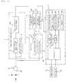
- FIG. 1 is a schematic view illustrating the whole set of an image processing system according to an embodiment of the present invention, that is, a system that acquires tomographic images of the ocular fundus of a subject's eye to perform image processing.
- an ocular fundus image capturing unit 1 for observation and image capturing of an ocular fundus (retina) Ef of a subject's eye E.
- the ocular fundus image capturing unit 1 may comprise a lighting optical system 4, an image capturing optical system 5, and an image capturing device 100 that is composed, for example, of a two-dimensional CCD or CMOS.
- the lighting optical system 4 may comprise an observation light source such as a halogen lamp and an image capturing light source such as a xenon lamp, and the light from these light sources is introduced to the ocular fundus Ef via the lighting optical system 4 to light the ocular fundus Ef.
- the image capturing optical system 5 may comprise an optical system that includes necessary components, such as an objective lens, image capturing lens and focusing lens, and introduces the image capturing light reflected by the ocular fundus Ef to the image capturing device 100 along an image capturing optical path to capture images of the ocular fundus Ef.
- Scanning unit 6 can introduce signal light (described later) reflected by the ocular fundus Ef to a tomographic image capturing unit 2.
- the scanning unit 6 may be a mechanism that comprises a known galvanometer mirror 11 for scanning the light from a low-coherence light source 20 of the tomographic image capturing unit 2 in the x-direction (horizontal direction) and y-direction (vertical direction), a focus optical system 12, and other necessary components.
- the scanning unit 6 is optically connected via a connector 7 and a connecting line 8 to the tomographic image capturing unit 2 which captures tomographic images of the ocular fundus Ef.
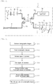
- the tomographic image capturing unit 2 may be a known one that operates using the Fourier domain scheme (spectral domain method), for example, and the detailed configuration is illustrated in FIG. 2 .
- the tomographic image capturing unit 2 may have a low-coherence light source 20 that emits light of a temporal coherence length of about several micrometers to several tens of micrometers at a wavelength of 700 nm to 1,100 nm.
- the low coherence light LO generated by the low-coherence light source 20 is introduced into an optical coupler 22 through an optical fiber 22a and divided into reference light LR and signal light LS.
- the reference light LR passes through an optical fiber 22b, a collimator lens 23, a glass block 24, and a density filter 25 and reaches a reference mirror 26 that is movable in the optical axis direction for matching the optical path lengths.
- the glass block 24 and the density filter 25 can function as a delay means for matching the optical path lengths (optical distances) of the reference light LR and signal light LS and can also function as a means for matching the dispersion characteristics of the reference light LR and signal light LS.
- the signal light LS passes through an optical fiber 22c inserted in the connecting line 8, reaches the ocular fundus Ef via the scanning unit 6 of FIG. 1 , and scans the ocular fundus in the horizontal direction (x-direction) and the vertical direction (y-direction).
- the signal light LS reaching the ocular fundus Ef is reflected at the ocular fundus Ef and tracks back the above path to return to the optical coupler 22.
- the reference light LR reflected from the reference mirror 26 and the signal light LS reflected from the ocular fundus Ef are superimposed by the optical coupler 22 to be interfering light LC.
- the interfering light LC is introduced into an OCT signal detecting device 21 via an optical fiber 22d.
- the interfering light LC is caused to be a parallel light flux by a collimator lens 21a, and the parallel light flux is then incident to a diffraction grating 21b to be diffracted and forms an image on a CCD 21d by an imaging lens 21c.
- the OCT signal detecting device 21 can generate an OCT signal that represents information regarding the depth direction (z-direction) of the ocular fundus by the diffracted interfering light.
- the image processing system may be provided with an image processing device 3 that is composed, for example, of a personal computer connected to the tomographic image capturing unit 2 and other necessary components.
- the image processing device 3 may be provided with a control section 30 that is composed of a CPU, a RAM, a ROM, and other necessary components.
- the control 30 can execute an image processing program to control the image processing as a whole.
- Display section 31 may be composed, for example, of a display device such as an LCD.
- the display section 31 can display images, such as tomographic images and a front image, which are generated or processed in the image processing device 3, and associated information such as information regarding the subject, etc.
- Input section 32 is for an input operation to the images displayed on the display section 31, using an input means such as a mouse, keyboard and input pen. An operator can use the input section 32 to provide commands to the image processing device 3, etc.
- the image processing device 3 may be provided with a tomographic image forming section 41.
- the tomographic image forming section 41 may be realized as a dedicated electronic circuit that executes a known analyzing method such as the Fourier domain method (spectral domain method) or realized using an image processing program that is executed by the previously-described CPU, and forms tomographic images of the ocular fundus Ef on the basis of the OCT signal detected by the OCT signal detecting device 21.
- the tomographic images formed by the tomographic image forming section 41 may be stored in a storage section 42 that is composed, for example, of a semiconductor memory, hard disk or the like.
- the storage section 42 may further store the above-described image processing program and other necessary programs and data.
- the image processing device 3 may be provided with an image processing section 50, which has an enhancement processing means 51, a region-of-interest setting means 52, a feature value extracting means 53, a disease determining means 54, and a mapping means 55.
- the enhancement processing means 51 enhances a speckle pattern in each tomographic image formed by the tomographic image forming section 41.
- the tomographic image formed by the tomographic image forming section 41 mere noises and a speckle pattern coexist and it is difficult to distinguish the noises and the speckle on the tomographic image.
- noises are removed as much as possible thereby to perform a process of enhancing the speckle pattern.
- the region-of-interest setting means 52 sets, as a region-of-interest, a desired region in each tomographic image of which the speckle pattern is enhanced by the enhancement processing means 51.
- the region-of-interest is generally a region from which an operator wants to obtain more detailed information regarding the state of the ocular fundus, but is not limited thereto, provided that the region is a closed region in the ocular fundus tissues appearing in the tomographic image. Since the ocular fundus tissues are in a layered structure, the region-of-interest may be set within one retina layer of the retina layer structure of the ocular fundus displayed in the tomographic image and may not be set across two or more retina layers.
- the feature value extracting means 53 extracts a feature value of the speckle pattern in the region-of-interest which is set by the region-of-interest setting means 52.
- the disease determining means 54 makes disease determination for the ocular fundus on the basis of the feature value which is extracted by the feature value extracting means 53. Examples of the disease determination for the ocular fundus include, for example, determining whether a disease of the ocular fundus is present or absent, determining the disease name, determining the stage of progression of the disease, and determining the degree of suspicion of the disease.
- the mapping means 55 may map, in the ocular fundus tomographic image, a site of the ocular fundus that is determined to have a disease by the disease determining means 54.
- This image processing may be performed by the control section 30 reading out the image processing program stored in the storage section 42 to execute it.
- the subject's eye E and the ocular fundus image capturing unit 1 are aligned and the ocular fundus Ef is caused to come into focus.
- the low-coherence light source 20 is turned on and the scanning unit 6 sweeps the signal light from the tomographic image capturing unit 2 in the x-direction and y-direction to scan the ocular fundus Ef.
- Region R in which a macular region of the retina exists may be scanned in a direction parallel to the x-axis with n scanning lines y 1 , y 2 , ..., y n .
- the signal light LS reflected from the ocular fundus Ef is superimposed in the tomographic image capturing unit 2 with the reference light LR reflected from the reference mirror 26. This superimposition generates the interfering light LC and the OCT signal detecting device 21 generates the OCT signal.
- the tomographic image forming section 41 forms the tomographic images of the ocular fundus Ef on the basis of the OCT signal (step S2) and the formed tomographic images are stored in the storage section 42.
- the time interval between t i and t i+1 corresponds to a time required for the next scanning line y i+1 to start.
- a speckle pattern SP may appear together with other noises.
- an arithmetic averaging process may be performed on a plurality of the tomographic images to remove the noises as much as possible and enhance only the speckle pattern SP thereby to improve the image quality of a tomographic image.
- the enhancement processing means 51 enhances the speckle pattern SP.
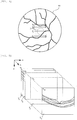
- FIG. 6 is an explanatory view illustrating the created arithmetically averaged image T a .
- L1 to L6 represent boundaries between layers in a retina layer structure. For descriptive purposes, the image is divided into four regions I1, I2, S1, and S2.
- the region-of-interest setting means 52 performs setting of a region-of-interest ROI for the arithmetically averaged image T a .
- the region-of-interest ROI may be set, as illustrated in FIG. 7 , within one retina layer of the retina layer structure of the ocular fundus displayed in the arithmetically averaged image T a .
- the region-of-interest ROI may not be set across two or more retina layers and may be set so as to avoid blood vessels B in the retina layer structure.
- the feature value extracting means 53 extracts a feature value of the speckle pattern SP in each region-of-interest ROI in step S5.
- the feature value of the speckle pattern SP in the region-of-interest ROI may be extracted in the following manner.
- the signal intensity is measured for each pixel in the region-of-interest ROI, and the image in the region-of-interest ROI is digitized by performing an imaging process of 256-gradation in accordance with the signal intensity.
- This digitized image data is used as the basis to create a histogram as illustrated in FIG. 8 , in which the horizontal axis represents the brightness and the vertical axis represents the count of pixels.
- ⁇ is a shape parameter and ⁇ is a scale parameter.
- the gamma distribution function is applied by giving initial values of ⁇ and ⁇ and searching for optimum values by repetitive operation.
- the feature value of the speckle pattern SP in the region-of-interest ROI can be represented by those two parameters and, in particular, the ratio ⁇ / ⁇ may be representative of the feature value of the speckle pattern SP in the region-of-interest ROI.
- the disease determining means 54 determines, in step S6, presence or absence of a disease in the region-of-interest ROI on the basis of the feature value.
- the storage section 42 may preliminarily store reference feature value data that represents the states of various ocular fundus tissues.
- the above process of steps S3 to S5 may be preliminarily performed to extract the feature values of speckle patterns from the tomographic images of ocular fundi of normal eyes and abnormal eyes having a disease, and a reference feature value database may be provided such that the feature values are stored in the storage section 42 as reference feature value data that is associated with the state of an ocular fundus.
- the feature value of the speckle pattern SP extracted in step S5 may be checked up with the feature value data of the reference feature value database to pick up reference feature value data that matches or approximates the feature value on the basis of the difference therebetween, and the state of ocular fundus tissues, such as the presence or absence of a disease and the stage of progression of the disease in the region-of-interest ROI, can be determined from the picked-up reference feature value data.
- the disease determination in step S6 may be performed as below.
- many tomographic images of ocular fundi of normal eyes and abnormal eyes having a disease may be prepared, the above process of steps S3 to S5 may be preliminarily performed to extract the feature values of speckle patterns from these tomographic images, and the relationship between the presence or absence of a disease and the parameters ⁇ and ⁇ or the relationship between the presence or absence of a disease and the ratio of ⁇ / ⁇ may be accumulated. Further, analysis may be performed as to which value when the parameters ⁇ and ⁇ or the ratio of ⁇ / ⁇ exceeds, a disease is recognized in the region-of-interest ROI, and a threshold to be used for the disease determination may be determined.
- the state of ocular fundus tissues such as the presence or absence of a disease and the stage of progression of the disease in the region-of-interest ROI, may be determined in accordance with whether the feature value of the speckle pattern extracted in step S5 exceeds the threshold.
- the mapping means 55 may map the site of the ocular fundus which is determined to have a disease, in the arithmetically averaged image T a .
- the disease site is mapped in the ocular fundus tomographic image and displayed, for example, by the display section 31, the result of disease determination can readily be perceived.
- the result can more readily be perceived.
- the speckle pattern can be utilized in a positive manner thereby to obtain more detailed information regarding the state of ocular fundus tissues from the ocular fundus tomographic image, and the disease determination for the ocular fundus can be performed.
Landscapes
- Health & Medical Sciences (AREA)
- Life Sciences & Earth Sciences (AREA)
- Engineering & Computer Science (AREA)
- Physics & Mathematics (AREA)
- General Health & Medical Sciences (AREA)
- Medical Informatics (AREA)
- General Physics & Mathematics (AREA)
- Surgery (AREA)
- Animal Behavior & Ethology (AREA)
- Biomedical Technology (AREA)
- Heart & Thoracic Surgery (AREA)
- Biophysics (AREA)
- Molecular Biology (AREA)
- Veterinary Medicine (AREA)
- Ophthalmology & Optometry (AREA)
- Public Health (AREA)
- Theoretical Computer Science (AREA)
- Nuclear Medicine, Radiotherapy & Molecular Imaging (AREA)
- Radiology & Medical Imaging (AREA)
- Computer Vision & Pattern Recognition (AREA)
- Signal Processing (AREA)
- Quality & Reliability (AREA)
- Eye Examination Apparatus (AREA)
Abstract
Description
- The present invention relates to an image processing device, image processing method and image processing program for processing tomographic images captured by a tomographic image capturing device or the like and generating an image suitable as a diagnostic image.
- Tomographic image capturing devices are put into practical use as a type of ophthalmic diagnostic device. The tomographic image capturing devices capture tomographic images of ocular fundi utilizing optical interference of so-called OCT (Optical Coherence Tomography).
- There is a technique of arithmetically averaging a plurality of images to improve the image quality of an ocular fundus image obtained by the OCT. When the image processing of arithmetically averaging a plurality of images is performed, a speckle pattern disappears. The speckle pattern as referred to herein is an image pattern based on a phenomenon that portions of high intensity and low intensity of scattered light occur due to an indefinitely large number of superpositions of scattered light from a scattering body in the object to be measured. This is a physical phenomenon similar to a so-called interference phenomenon and the speckle pattern itself does not directly represent the structure of an ocular fundus that is the object to be measured. In this context,
Patent Literature 1 discloses a technique of regarding the speckle pattern as noises and combining tomographic images thereby to cause the speckle pattern to disappear, thus obtaining a high-quality tomographic image. - On the other hand,
Patent Literature 2 discloses an ultrasonograph that obtains an ultrasonographic image in a subject under test on the basis of echo signals of ultrasonic waves. This ultrasonograph is provided with an analysis algorithm capable of observing a lesion by positively taking advantage of a speckle pattern appearing in the ultrasonographic image and utilizing its statistical properties to smooth an image of the speckle part and extract a microstructure. This literature also discloses a technique of utilizing a phenomenon that the probability density distribution of brightness values of echo signals reflected from a normal liver follows the Rayleigh distribution and comparing the variance values to determine whether the probability density distribution obtained by actual measurement follows the Rayleigh distribution as the theoretical figure. -
Non-Patent Literature 1 discloses that the speckle pattern of OCT can be quantified in accordance with the gamma distribution. -
- [Patent Literature 1]
JP2013-183909A - [Patent Literature 2]
JP2011-224410A - [Non-Patent Literature 1] Texture analysis of OCT speckle for characterizing biological tissues in vivo, Optics Letters, 38(8), 2013.
- As described above, the speckle pattern itself does not directly represent the structure of an ocular fundus as the object to be measured, but is recognized to vary in the appearance in accordance with the state of ocular fundus. The present inventor has therefore focused attention on, rather than merely regarding the speckle pattern as noises, positively taking advantage of its statistical properties thereby to obtain more detailed information regarding the state of ocular fundus from the tomographic image of the ocular fundus.
- In particular, as suggested in Non-Patent
Literature 1, a feature value of the speckle pattern can be quantified for each image by utilizing the phenomenon that the speckle pattern follows the gamma distribution. Disease determination will thus be possible if more detailed information regarding the state of ocular fundus is obtained on the basis of data in which the feature value of the speckle pattern is quantified. - Therefore, objects of the present invention include providing an image processing device, image processing method and image processing program that utilize the speckle pattern in a positive manner thereby to obtain more detailed information regarding the state of ocular fundus tissues from the ocular fundus tomographic image and can perform disease determination for the ocular fundus, rather than owing to an idea of merely improving the image quality of the OCT ocular fundus tomographic image thereby to improve the visibility of the ocular fundus tomographic image as in the prior art.
- To achieve the above objects, according to a first aspect of the present invention, there is provided an image processing device comprising: an enhancement processing means configured to enhance a speckle pattern in an ocular fundus tomographic image; a region-of-interest setting means configured to set a desired region in the ocular fundus tomographic image with the enhanced speckle pattern as a region-of-interest; a feature value extracting means configured to extract a feature value of the speckle pattern in the region-of-interest; and a disease determining means configured to make disease determination for an ocular fundus on the basis of the feature value (Invention 1).
- According to the above invention (Invention 1), detailed information regarding the state of ocular fundus tissues, which would not be completely perceived from the conventional OCT ocular fundus tomographic image, can be obtained by positively utilizing the speckle pattern in the ocular fundus tomographic image to perform the disease determination for the ocular fundus in each region-of-interest. The disease determination in the present invention refers to a concept including not only determining merely whether a disease of the ocular fundus is present or absent but also all possible determinations regarding a disease of the ocular fundus, such as determining the disease name, determining the stage of progression of the disease, and determining the degree of suspicion of the disease.
- In the above invention (Invention 1), it is preferred that the region-of-interest is set within one retina layer of a retina layer structure displayed in the ocular fundus tomographic image (Invention 2).
- According to the above invention (Invention 2), the region-of-interest is set within one retina layer so as not to be set across two or more retina layers, and the feature value analysis for the speckle pattern can thereby be individually executed for each region in the retina layer structure. Therefore, the accuracy of evaluation is improved, and more detailed information regarding the state of ocular fundus tissues can be obtained.
- In the above invention (
Invention 1, 2), it is preferred that the image processing device further comprises a mapping means configured to map, in the ocular fundus tomographic image, a site of the ocular fundus that is determined to have a disease by the disease determining means (Invention 3). - According to the above invention (Invention 3), the disease site is mapped in the ocular fundus tomographic image and thereby the result of disease determination can readily be perceived.
- In the above invention (
Invention 1 to 3), it is preferred that the enhancement processing means selects a plurality of ocular fundus tomographic images having similar speckle patterns from among a plurality of captured ocular fundus tomographic images and performs an arithmetic averaging process on the selected plurality of ocular fundus tomographic images having similar speckle patterns (Invention 4). - In the above invention (
Invention 1 to 4), it is preferred that the feature value extracting means creates a histogram on the basis of brightness of the speckle pattern (Invention 5). - In the above invention (
Invention 1 to 5), the disease determining means may compare the feature value of the speckle pattern with a reference feature value that is preliminarily acquired (Invention 6) or may also formulate the feature value of the speckle pattern into a mathematical formula and perform the disease determination on the basis of whether a parameter in the mathematical formula exceeds a predetermined threshold (Invention 7). - According to a second aspect of the present invention, there is provided an image processing method comprising: a step of enhancing a speckle pattern in an ocular fundus tomographic image; a step of setting a desired region in the ocular fundus tomographic image with the enhanced speckle pattern as a region-of-interest; a step of extracting a feature value of the speckle pattern in the region-of-interest; and a step of making disease determination for an ocular fundus on the basis of the feature value (Invention 8).
- According to the above invention (Invention 8), detailed information regarding the state of ocular fundus tissues, which would not be completely perceived from the conventional OCT ocular fundus tomographic image, can be obtained by positively utilizing the speckle pattern in the ocular fundus tomographic image to perform the disease determination for the ocular fundus in each region-of-interest.
- In the above invention (Invention 8), it is preferred that the region-of-interest is set within one retina layer of a retina layer structure displayed in the ocular fundus tomographic image (Invention 9).
- According to the above invention (Invention 9), the region-of-interest is set within one retina layer so as not to be set across two or more retina layers, and the feature value analysis for the speckle pattern can thereby be individually executed for each region in the retina layer structure. Therefore, the accuracy of evaluation is improved, and more detailed information regarding the state of ocular fundus tissues can be obtained.
- In the above invention (
Invention 8, 9), it is preferred that the image processing method further comprises a step of mapping, in the ocular fundus tomographic image, a site of the ocular fundus that is determined to have a disease in the step of performing disease determination (Invention 10). - According to the above invention (Invention 10), the disease site is mapped in the ocular fundus tomographic image and thereby the result of disease determination can readily be perceived.
- In the above invention (
Invention 8 to 10), it is preferred that the step of enhancing a speckle pattern is a step of selecting a plurality of ocular fundus tomographic images having similar speckle patterns from among a plurality of captured ocular fundus tomographic images and performing an arithmetic averaging process on the selected plurality of ocular fundus tomographic images having similar speckle patterns (Invention 11). - In the above invention (
Invention 8 to 11), it is preferred that the step of extracting a feature value is a step of creating a histogram on the basis of brightness of the speckle pattern (Invention 12). - In the above invention (
Invention 8 to 12), the step of performing disease determination may be a step of comparing the feature value of the speckle pattern with a reference feature value that is preliminarily acquired (Invention 13) or may also be a step of formulating the feature value of the speckle pattern into a mathematical formula and performing the disease determination on the basis of whether a parameter in the mathematical formula exceeds a predetermined threshold (Invention 14). - According to a third aspect of the present invention, there is provided an image processing program that is characterized by causing a computer to execute the image processing method as described in any one of
Invention 8 to 14 (Invention 15). - According to the above invention (Invention 15), detailed information regarding the state of ocular fundus tissues, which would not be completely perceived from the conventional OCT ocular fundus tomographic image, can be obtained by positively utilizing the speckle pattern in the ocular fundus tomographic image to perform the disease determination for the ocular fundus in each region-of-interest.
- According to the image processing device, image processing method and image processing program of the present invention, it is possible to utilize the speckle pattern in a positive manner thereby to obtain more detailed information regarding the state of ocular fundus tissues from the ocular fundus tomographic image and perform disease determination for the ocular fundus.
-
- [
FIG. 1] FIG. 1 is a schematic view illustrating an image processing system according to an embodiment of the present invention. - [
FIG. 2] FIG. 2 is an optics view illustrating the detailed configuration of a tomographic image capturing unit according to the embodiment. - [
FIG. 3] FIG. 3 is a flowchart illustrating the flow of image processing according to the embodiment. - [
FIG. 4] FIG. 4 is an explanatory view illustrating a state of scanning an ocular fundus with signal light in the embodiment. - [
FIG. 5] FIG. 5 is an explanatory view illustrating a state of acquiring a plurality of tomographic images in the embodiment. - [
FIG. 6] FIG. 6 is an explanatory view illustrating an arithmetically averaged image created in the embodiment. - [
FIG. 7] FIG. 7 is a set of explanatory views each illustrating an example of setting a region-of-interest in the embodiment. - [
FIG. 8] FIG. 8 is a histogram created in the embodiment. [Embodiments for Carrying out the Invention] - Hereinafter, embodiments of the present invention will be described in detail with reference to the drawings.
-
FIG. 1 is a schematic view illustrating the whole set of an image processing system according to an embodiment of the present invention, that is, a system that acquires tomographic images of the ocular fundus of a subject's eye to perform image processing. What is denoted byreference numeral 1 is an ocular fundusimage capturing unit 1 for observation and image capturing of an ocular fundus (retina) Ef of a subject's eye E. The ocular fundusimage capturing unit 1 may comprise a lightingoptical system 4, an image capturingoptical system 5, and an image capturingdevice 100 that is composed, for example, of a two-dimensional CCD or CMOS. - The lighting
optical system 4 may comprise an observation light source such as a halogen lamp and an image capturing light source such as a xenon lamp, and the light from these light sources is introduced to the ocular fundus Ef via the lightingoptical system 4 to light the ocular fundus Ef. The image capturingoptical system 5 may comprise an optical system that includes necessary components, such as an objective lens, image capturing lens and focusing lens, and introduces the image capturing light reflected by the ocular fundus Ef to theimage capturing device 100 along an image capturing optical path to capture images of the ocular fundus Ef. -
Scanning unit 6 can introduce signal light (described later) reflected by the ocular fundus Ef to a tomographicimage capturing unit 2. Thescanning unit 6 may be a mechanism that comprises a knowngalvanometer mirror 11 for scanning the light from a low-coherence light source 20 of the tomographicimage capturing unit 2 in the x-direction (horizontal direction) and y-direction (vertical direction), a focusoptical system 12, and other necessary components. - The
scanning unit 6 is optically connected via aconnector 7 and a connectingline 8 to the tomographicimage capturing unit 2 which captures tomographic images of the ocular fundus Ef. - The tomographic
image capturing unit 2 may be a known one that operates using the Fourier domain scheme (spectral domain method), for example, and the detailed configuration is illustrated inFIG. 2 . The tomographicimage capturing unit 2 may have a low-coherence light source 20 that emits light of a temporal coherence length of about several micrometers to several tens of micrometers at a wavelength of 700 nm to 1,100 nm. - The low coherence light LO generated by the low-
coherence light source 20 is introduced into anoptical coupler 22 through anoptical fiber 22a and divided into reference light LR and signal light LS. The reference light LR passes through anoptical fiber 22b, acollimator lens 23, aglass block 24, and adensity filter 25 and reaches areference mirror 26 that is movable in the optical axis direction for matching the optical path lengths. Theglass block 24 and thedensity filter 25 can function as a delay means for matching the optical path lengths (optical distances) of the reference light LR and signal light LS and can also function as a means for matching the dispersion characteristics of the reference light LR and signal light LS. - The signal light LS passes through an
optical fiber 22c inserted in the connectingline 8, reaches the ocular fundus Ef via thescanning unit 6 ofFIG. 1 , and scans the ocular fundus in the horizontal direction (x-direction) and the vertical direction (y-direction). The signal light LS reaching the ocular fundus Ef is reflected at the ocular fundus Ef and tracks back the above path to return to theoptical coupler 22. - The reference light LR reflected from the
reference mirror 26 and the signal light LS reflected from the ocular fundus Ef are superimposed by theoptical coupler 22 to be interfering light LC. The interfering light LC is introduced into an OCTsignal detecting device 21 via anoptical fiber 22d. In the OCTsignal detecting device 21, the interfering light LC is caused to be a parallel light flux by acollimator lens 21a, and the parallel light flux is then incident to adiffraction grating 21b to be diffracted and forms an image on aCCD 21d by animaging lens 21c. The OCTsignal detecting device 21 can generate an OCT signal that represents information regarding the depth direction (z-direction) of the ocular fundus by the diffracted interfering light. - The image processing system according to the present embodiment may be provided with an
image processing device 3 that is composed, for example, of a personal computer connected to the tomographicimage capturing unit 2 and other necessary components. Theimage processing device 3 may be provided with acontrol section 30 that is composed of a CPU, a RAM, a ROM, and other necessary components. Thecontrol 30 can execute an image processing program to control the image processing as a whole. -
Display section 31 may be composed, for example, of a display device such as an LCD. Thedisplay section 31 can display images, such as tomographic images and a front image, which are generated or processed in theimage processing device 3, and associated information such as information regarding the subject, etc. -
Input section 32 is for an input operation to the images displayed on thedisplay section 31, using an input means such as a mouse, keyboard and input pen. An operator can use theinput section 32 to provide commands to theimage processing device 3, etc. - The
image processing device 3 may be provided with a tomographic image forming section 41. The tomographic image forming section 41 may be realized as a dedicated electronic circuit that executes a known analyzing method such as the Fourier domain method (spectral domain method) or realized using an image processing program that is executed by the previously-described CPU, and forms tomographic images of the ocular fundus Ef on the basis of the OCT signal detected by the OCTsignal detecting device 21. The tomographic images formed by the tomographic image forming section 41 may be stored in astorage section 42 that is composed, for example, of a semiconductor memory, hard disk or the like. Thestorage section 42 may further store the above-described image processing program and other necessary programs and data. - The
image processing device 3 may be provided with animage processing section 50, which has an enhancement processing means 51, a region-of-interest setting means 52, a featurevalue extracting means 53, a disease determining means 54, and a mapping means 55. - The enhancement processing means 51 enhances a speckle pattern in each tomographic image formed by the tomographic image forming section 41. In the tomographic image formed by the tomographic image forming section 41, mere noises and a speckle pattern coexist and it is difficult to distinguish the noises and the speckle on the tomographic image. In order to obtain more detailed information regarding the state of ocular fundus tissues from the ocular fundus tomographic image by utilizing the speckle pattern in a positive manner, in the present embodiment, noises are removed as much as possible thereby to perform a process of enhancing the speckle pattern.
- The region-of-interest setting means 52 sets, as a region-of-interest, a desired region in each tomographic image of which the speckle pattern is enhanced by the enhancement processing means 51. The region-of-interest is generally a region from which an operator wants to obtain more detailed information regarding the state of the ocular fundus, but is not limited thereto, provided that the region is a closed region in the ocular fundus tissues appearing in the tomographic image. Since the ocular fundus tissues are in a layered structure, the region-of-interest may be set within one retina layer of the retina layer structure of the ocular fundus displayed in the tomographic image and may not be set across two or more retina layers.
- The feature
value extracting means 53 extracts a feature value of the speckle pattern in the region-of-interest which is set by the region-of-interest setting means 52. The disease determining means 54 makes disease determination for the ocular fundus on the basis of the feature value which is extracted by the featurevalue extracting means 53. Examples of the disease determination for the ocular fundus include, for example, determining whether a disease of the ocular fundus is present or absent, determining the disease name, determining the stage of progression of the disease, and determining the degree of suspicion of the disease. The mapping means 55 may map, in the ocular fundus tomographic image, a site of the ocular fundus that is determined to have a disease by thedisease determining means 54. - Next, the image processing in the present embodiment will be described with reference to the flowchart illustrated in
FIG. 3 . This image processing may be performed by thecontrol section 30 reading out the image processing program stored in thestorage section 42 to execute it. - First, prior to the image capturing of the tomographic images performed in step S1, the subject's eye E and the ocular fundus
image capturing unit 1 are aligned and the ocular fundus Ef is caused to come into focus. In this state, the low-coherence light source 20 is turned on and thescanning unit 6 sweeps the signal light from the tomographicimage capturing unit 2 in the x-direction and y-direction to scan the ocular fundus Ef. This state is illustrated inFIG. 4 . Region R in which a macular region of the retina exists may be scanned in a direction parallel to the x-axis with n scanning lines y1, y2 , ..., yn. - The signal light LS reflected from the ocular fundus Ef is superimposed in the tomographic
image capturing unit 2 with the reference light LR reflected from thereference mirror 26. This superimposition generates the interfering light LC and the OCTsignal detecting device 21 generates the OCT signal. The tomographic image forming section 41 forms the tomographic images of the ocular fundus Ef on the basis of the OCT signal (step S2) and the formed tomographic images are stored in thestorage section 42. -
FIG. 5 illustrates tomographic images Ti (i=1 to N) each at different time ti (i=1 to N) of an xz-tomographic image (B-scan image) obtained by the scanning line yj passing through approximately the center of the macular region of the retina. The time interval between ti and ti+1 corresponds to a time required for the next scanning line yi+1 to start. These tomographic images Ti (i=1 to N) may be formed every time ti (i=1 to N) in the tomographic image forming section 41 and stored sequentially in thestorage section 42. - In each of the tomographic images stored sequentially in the
storage section 42, a speckle pattern SP may appear together with other noises. In the present embodiment, an arithmetic averaging process may be performed on a plurality of the tomographic images to remove the noises as much as possible and enhance only the speckle pattern SP thereby to improve the image quality of a tomographic image. - In the present embodiment, 100 images of the tomographic images Ti (i=1 to N) may be formed in the same site at different times (i.e. N=100) and stored in the
storage section 42. Then, in step S3, the enhancement processing means 51 enhances the speckle pattern SP. Specifically, the enhancement processing means 51 may select 10 images of tomographic images having similar speckle patterns SP from among the 100 images of the tomographic images Ti (i=1 to N), read out the 10 images of the tomographic images from thestorage section 42, and perform arithmetic averaging on each pixel to create an arithmetically averaged image Ta. The speckle pattern SP does not disappear after the arithmetic averaging because the speckle pattern SP is similar in the selected 10 images of tomographic images, but the noises other than the speckle pattern SP disappear by the arithmetic averaging. Therefore, the arithmetically averaged image Ta has improved image quality as a whole and the speckle pattern SP can easily be recognized. The arithmetically averaged image Ta thus created may be stored in thestorage section 42.FIG. 6 is an explanatory view illustrating the created arithmetically averaged image Ta. In the arithmetically averaged image Ta, L1 to L6 represent boundaries between layers in a retina layer structure. For descriptive purposes, the image is divided into four regions I1, I2, S1, and S2. - Subsequently, in step S4, the region-of-interest setting means 52 performs setting of a region-of-interest ROI for the arithmetically averaged image Ta. Specifically, the region-of-interest ROI may be set, as illustrated in
FIG. 7 , within one retina layer of the retina layer structure of the ocular fundus displayed in the arithmetically averaged image Ta. The region-of-interest ROI may not be set across two or more retina layers and may be set so as to avoid blood vessels B in the retina layer structure. By setting the region-of-interest ROI in such a manner, the feature value analysis for the speckle pattern SP can be individually executed for each region in the retina layer structure. Therefore, the accuracy of evaluation is improved, and more detailed information regarding the state of ocular fundus tissues can be obtained. - After the region-of-interest ROI is set, the feature
value extracting means 53 extracts a feature value of the speckle pattern SP in each region-of-interest ROI in step S5. Specifically, the feature value of the speckle pattern SP in the region-of-interest ROI may be extracted in the following manner. First, the signal intensity is measured for each pixel in the region-of-interest ROI, and the image in the region-of-interest ROI is digitized by performing an imaging process of 256-gradation in accordance with the signal intensity. This digitized image data is used as the basis to create a histogram as illustrated inFIG. 8 , in which the horizontal axis represents the brightness and the vertical axis represents the count of pixels. Here, the knowledge is utilized that the speckle pattern of OCT can be quantified in accordance with the gamma distribution, and the gamma distribution function represented byExpression 1 is applied to that histogram using nonlinear regression analysis.
- In
Expression 1, α is a shape parameter and β is a scale parameter. The gamma distribution function is applied by giving initial values of α and β and searching for optimum values by repetitive operation. The feature value of the speckle pattern SP in the region-of-interest ROI can be represented by those two parameters and, in particular, the ratio α/β may be representative of the feature value of the speckle pattern SP in the region-of-interest ROI. - After the feature value of the speckle pattern SP in the region-of-interest ROI is extracted, the disease determining means 54 determines, in step S6, presence or absence of a disease in the region-of-interest ROI on the basis of the feature value. Specifically, for making the disease determination, the
storage section 42 may preliminarily store reference feature value data that represents the states of various ocular fundus tissues. For example, the above process of steps S3 to S5 may be preliminarily performed to extract the feature values of speckle patterns from the tomographic images of ocular fundi of normal eyes and abnormal eyes having a disease, and a reference feature value database may be provided such that the feature values are stored in thestorage section 42 as reference feature value data that is associated with the state of an ocular fundus. Then, the feature value of the speckle pattern SP extracted in step S5 may be checked up with the feature value data of the reference feature value database to pick up reference feature value data that matches or approximates the feature value on the basis of the difference therebetween, and the state of ocular fundus tissues, such as the presence or absence of a disease and the stage of progression of the disease in the region-of-interest ROI, can be determined from the picked-up reference feature value data. - In an alternative embodiment, the disease determination in step S6 may be performed as below. For example, many tomographic images of ocular fundi of normal eyes and abnormal eyes having a disease may be prepared, the above process of steps S3 to S5 may be preliminarily performed to extract the feature values of speckle patterns from these tomographic images, and the relationship between the presence or absence of a disease and the parameters α and β or the relationship between the presence or absence of a disease and the ratio of α/β may be accumulated. Further, analysis may be performed as to which value when the parameters α and β or the ratio of α/β exceeds, a disease is recognized in the region-of-interest ROI, and a threshold to be used for the disease determination may be determined. Then, the state of ocular fundus tissues, such as the presence or absence of a disease and the stage of progression of the disease in the region-of-interest ROI, may be determined in accordance with whether the feature value of the speckle pattern extracted in step S5 exceeds the threshold.
- Subsequently, in step S7, the mapping means 55 may map the site of the ocular fundus which is determined to have a disease, in the arithmetically averaged image Ta. When the disease site is mapped in the ocular fundus tomographic image and displayed, for example, by the
display section 31, the result of disease determination can readily be perceived. As will be understood, if the disease site is mapped with color in the ocular fundus tomographic image, the result can more readily be perceived. - When the image processing is performed in the above manner, the speckle pattern can be utilized in a positive manner thereby to obtain more detailed information regarding the state of ocular fundus tissues from the ocular fundus tomographic image, and the disease determination for the ocular fundus can be performed.
- The image processing system according to the present invention has been heretofore described with reference to the drawings, but the present invention is not limited to the above embodiments and various modified embodiments can be carried out.
-
- 1
- Ocular fundus image capturing unit
- 2
- Tomographic image capturing unit
- 3
- Image processing device
- 4
- Lighting optical system
- 5
- Image capturing optical system
- 6
- Scanning unit
- 20
- Low-coherence light source
- 21
- OCT signal detecting device
- 30
- Control section
- 31
- Display section
- 32
- Input section
- 41
- Tomographic image forming section
- 42
- Storage section
- 50
- Image processing section
- 51
- Enhancement processing means
- 52
- Region-of-interest setting means
- 53
- Feature value extracting means
- 54
- Disease determining means
- 55
- Mapping means
- 100
- Image capturing device
Claims (15)
- An image processing device comprising:an enhancement processing means configured to enhance a speckle pattern in an ocular fundus tomographic image;a region-of-interest setting means configured to set a desired region in the ocular fundus tomographic image with the enhanced speckle pattern as a region-of-interest;a feature value extracting means configured to extract a feature value of the speckle pattern in the region-of-interest; anda disease determining means configured to make disease determination for an ocular fundus on a basis of the feature value.
- The image processing device as recited in claim 1, wherein the region-of-interest is set within one retina layer of a retina layer structure displayed in the ocular fundus tomographic image.
- The image processing device as recited in claim 1 or 2, further comprising
a mapping means configured to map, in the ocular fundus tomographic image, a site of the ocular fundus that is determined to have a disease by the disease determining means. - The image processing device as recited in any one of claims 1 to 3, wherein the enhancement processing means selects a plurality of ocular fundus tomographic images having similar speckle patterns from among a plurality of captured ocular fundus tomographic images and performs an arithmetic averaging process on the selected plurality of ocular fundus tomographic images having similar speckle patterns.
- The image processing device as recited in any one of claims 1 to 4, wherein the feature value extracting means creates a histogram on a basis of brightness of the speckle pattern.
- The image processing device as recited in any one of claims 1 to 5, wherein the disease determining means compares the feature value of the speckle pattern with a reference feature value that is preliminarily acquired.
- The image processing device as recited in any one of claims 1 to 5, wherein the disease determining means formulates the feature value of the speckle pattern into a mathematical formula and performs the disease determination on a basis of whether a parameter in the mathematical formula exceeds a predetermined threshold.
- An image processing method comprising:a step of enhancing a speckle pattern in an ocular fundus tomographic image;a step of setting a desired region in the ocular fundus tomographic image with the enhanced speckle pattern as a region-of-interest;a step of extracting a feature value of the speckle pattern in the region-of-interest; anda step of making disease determination for an ocular fundus on a basis of the feature value.
- The image processing method as recited in claim 8, wherein the region-of-interest is set within one retina layer of a retina layer structure displayed in the ocular fundus tomographic image.
- The image processing method as recited in claim 8 or 9, further comprising
a step of mapping, in the ocular fundus tomographic image, a site of the ocular fundus that is determined to have a disease in the step of performing disease determination. - The image processing method as recited in any one of claims 8 to 10, wherein the step of enhancing a speckle pattern includes selecting a plurality of ocular fundus tomographic images having similar speckle patterns from among a plurality of captured ocular fundus tomographic images and performing an arithmetic averaging process on the selected plurality of ocular fundus tomographic images having similar speckle patterns.
- The image processing method as recited in any one of claims 8 to 11, wherein the step of extracting a feature value includes creating a histogram on a basis of brightness of the speckle pattern.
- The image processing method as recited in any one of claims 8 to 12, wherein the step of performing disease determination includes comparing the feature value of the speckle pattern with a reference feature value that is preliminarily acquired.
- The image processing method as recited in any one of claims 8 to 12, wherein the step of performing disease determination includes formulating the feature value of the speckle pattern into a mathematical formula and performing the disease determination on a basis of whether a parameter in the mathematical formula exceeds a predetermined threshold.
- An image processing program that causes a computer to execute the image processing method as recited in any one of claims 8 to 14.
Applications Claiming Priority (2)
| Application Number | Priority Date | Filing Date | Title |
|---|---|---|---|
| JP2014095299 | 2014-05-02 | ||
| PCT/JP2015/063054 WO2015167005A1 (en) | 2014-05-02 | 2015-05-01 | Image-processing device, image-processing method and image-processing program |
Publications (2)
| Publication Number | Publication Date |
|---|---|
| EP3138472A1 true EP3138472A1 (en) | 2017-03-08 |
| EP3138472A4 EP3138472A4 (en) | 2018-01-17 |
Family
ID=54358726
Family Applications (1)
| Application Number | Title | Priority Date | Filing Date |
|---|---|---|---|
| EP15785245.0A Withdrawn EP3138472A4 (en) | 2014-05-02 | 2015-05-01 | Image-processing device, image-processing method and image-processing program |
Country Status (4)
| Country | Link |
|---|---|
| US (1) | US10111582B2 (en) |
| EP (1) | EP3138472A4 (en) |
| JP (1) | JP6643982B2 (en) |
| WO (1) | WO2015167005A1 (en) |
Families Citing this family (7)
| Publication number | Priority date | Publication date | Assignee | Title |
|---|---|---|---|---|
| FR3036607A1 (en) * | 2015-05-26 | 2016-12-02 | Centre Nat Rech Scient | DEVICE FOR DETECTING A CONDITION OF THE CORNE OF THE EYE AND ASSOCIATED METHOD |
| JP6532762B2 (en) * | 2015-06-02 | 2019-06-19 | 株式会社東芝 | INFORMATION GENERATION SYSTEM, APPARATUS, METHOD, AND PROGRAM |
| JP7071650B2 (en) * | 2019-06-19 | 2022-05-19 | 日亜化学工業株式会社 | Image acquisition device |
| KR102306279B1 (en) * | 2020-01-29 | 2021-09-29 | 자이메드 주식회사 | Method for facilitating diagnosis of fundus image, apparatus therefor and system including the same |
| KR102396522B1 (en) * | 2020-07-28 | 2022-05-10 | 가톨릭대학교 산학협력단 | Method and system for discriminating pathological myopia using geometry of posterior sclera of fundus |
| KR102773723B1 (en) * | 2021-01-25 | 2025-02-28 | 자이메드 주식회사 | Apparatus and method for supporting reading of biometric imageme |
| CN116363132B (en) * | 2023-06-01 | 2023-08-22 | 中南大学湘雅医院 | Ophthalmic image processing method and system |
Family Cites Families (14)
| Publication number | Priority date | Publication date | Assignee | Title |
|---|---|---|---|---|
| JPH02232030A (en) * | 1989-03-06 | 1990-09-14 | Kowa Co | Ophthalmology diagnostic method |
| EP0389120B1 (en) | 1989-03-06 | 1995-01-18 | Kowa Company Ltd. | Ophthalmological diagnosis method |
| US5594807A (en) | 1994-12-22 | 1997-01-14 | Siemens Medical Systems, Inc. | System and method for adaptive filtering of images based on similarity between histograms |
| ATE454845T1 (en) | 2000-10-30 | 2010-01-15 | Gen Hospital Corp | OPTICAL SYSTEMS FOR TISSUE ANALYSIS |
| EP2166934A4 (en) | 2007-07-06 | 2012-10-17 | Ind Res Ltd | SYSTEMS AND METHOD FOR SHAPING LASER SPECKLES |
| US20120150029A1 (en) * | 2008-12-19 | 2012-06-14 | University Of Miami | System and Method for Detection and Monitoring of Ocular Diseases and Disorders using Optical Coherence Tomography |
| JP6116477B2 (en) * | 2010-05-28 | 2017-04-19 | ザ ジェネラル ホスピタル コーポレイション | Device for analyzing information on cardiovascular disease and cardiac function |
| JP5727198B2 (en) | 2010-11-05 | 2015-06-03 | 株式会社ニデック | Ophthalmic equipment |
| EP2449957B1 (en) | 2010-11-05 | 2015-03-25 | Nidek Co., Ltd. | Control method of a fundus examination apparatus |
| EP2667778B1 (en) | 2011-01-28 | 2021-04-28 | Bar Ilan University | Method and system for non-invasively monitoring biological or biochemical parameters of individual |
| JP5389118B2 (en) | 2011-08-19 | 2014-01-15 | 株式会社東芝 | Ultrasonic diagnostic equipment |
| JP6226510B2 (en) * | 2012-01-27 | 2017-11-08 | キヤノン株式会社 | Image processing system, processing method, and program |
| JP6025349B2 (en) | 2012-03-08 | 2016-11-16 | キヤノン株式会社 | Image processing apparatus, optical coherence tomography apparatus, image processing method, and optical coherence tomography method |
| KR102025756B1 (en) * | 2013-01-04 | 2019-09-27 | 삼성전자주식회사 | Method, Apparatus and system for reducing speckles on image |
-
2015
- 2015-05-01 EP EP15785245.0A patent/EP3138472A4/en not_active Withdrawn
- 2015-05-01 US US15/307,887 patent/US10111582B2/en not_active Expired - Fee Related
- 2015-05-01 WO PCT/JP2015/063054 patent/WO2015167005A1/en not_active Ceased
- 2015-05-01 JP JP2016516420A patent/JP6643982B2/en not_active Expired - Fee Related
Also Published As
| Publication number | Publication date |
|---|---|
| JPWO2015167005A1 (en) | 2017-04-20 |
| JP6643982B2 (en) | 2020-02-12 |
| US10111582B2 (en) | 2018-10-30 |
| US20170049314A1 (en) | 2017-02-23 |
| EP3138472A4 (en) | 2018-01-17 |
| WO2015167005A1 (en) | 2015-11-05 |
Similar Documents
| Publication | Publication Date | Title |
|---|---|---|
| US10111582B2 (en) | Image processing device and method to identify disease in an ocular fundus image | |
| US10660515B2 (en) | Image display method of providing diagnosis information using three-dimensional tomographic data | |
| JP5631032B2 (en) | Image processing apparatus, image processing system, image processing method, and program for causing computer to execute image processing | |
| JP4940069B2 (en) | Fundus observation apparatus, fundus image processing apparatus, and program | |
| US8761481B2 (en) | Image processing apparatus for processing tomographic image of subject's eye, imaging system, method for processing image, and recording medium | |
| JP5645432B2 (en) | Image processing apparatus, image processing system, image processing method, and program for causing computer to execute image processing | |
| JP6702764B2 (en) | Optical coherence tomographic data processing method, program for executing the method, and processing apparatus | |
| US10165939B2 (en) | Ophthalmologic apparatus and ophthalmologic apparatus control method | |
| US9642519B2 (en) | Image processing apparatus and control method of image processing apparatus | |
| US9335155B2 (en) | Imaging apparatus, image processing apparatus, and image processing method | |
| JP7195745B2 (en) | Image processing device, image processing method and program | |
| JP2015160105A (en) | Image processing device, image processing method and program | |
| JP7009265B2 (en) | Image processing equipment, image processing methods and programs | |
| JP7106304B2 (en) | Image processing device, image processing method and program | |
| JP2018057828A (en) | Image processing apparatus and image processing method | |
| US10916012B2 (en) | Image processing apparatus and image processing method | |
| JP6375760B2 (en) | Optical coherence tomography apparatus and fundus image processing program | |
| Baroni et al. | Texture classification of retinal layers in optical coherence tomography | |
| JP2018191761A (en) | Information processing apparatus, information processing method, and program | |
| JP2018047084A (en) | Ophthalmologic examination apparatus | |
| JP2019092920A (en) | Ophthalmic information processing apparatus, ophthalmic system, ophthalmic information processing method, and program | |
| JP6461937B2 (en) | Image processing apparatus, image processing method, and image processing program | |
| JP6461936B2 (en) | Image processing apparatus, image processing method, and image processing program | |
| JPWO2018079765A1 (en) | Image processing apparatus, fundus imaging system, image processing method, and program | |
| JP2019154717A (en) | Image processing apparatus, image processing method, and program |
Legal Events
| Date | Code | Title | Description |
|---|---|---|---|
| STAA | Information on the status of an ep patent application or granted ep patent |
Free format text: STATUS: THE INTERNATIONAL PUBLICATION HAS BEEN MADE |
|
| PUAI | Public reference made under article 153(3) epc to a published international application that has entered the european phase |
Free format text: ORIGINAL CODE: 0009012 |
|
| STAA | Information on the status of an ep patent application or granted ep patent |
Free format text: STATUS: REQUEST FOR EXAMINATION WAS MADE |
|
| 17P | Request for examination filed |
Effective date: 20161111 |
|
| AK | Designated contracting states |
Kind code of ref document: A1 Designated state(s): AL AT BE BG CH CY CZ DE DK EE ES FI FR GB GR HR HU IE IS IT LI LT LU LV MC MK MT NL NO PL PT RO RS SE SI SK SM TR |
|
| AX | Request for extension of the european patent |
Extension state: BA ME |
|
| DAV | Request for validation of the european patent (deleted) | ||
| DAX | Request for extension of the european patent (deleted) | ||
| RIC1 | Information provided on ipc code assigned before grant |
Ipc: A61B 3/10 20060101AFI20171128BHEP |
|
| A4 | Supplementary search report drawn up and despatched |
Effective date: 20171218 |
|
| RIC1 | Information provided on ipc code assigned before grant |
Ipc: A61B 3/10 20060101AFI20171208BHEP |
|
| STAA | Information on the status of an ep patent application or granted ep patent |
Free format text: STATUS: THE APPLICATION IS DEEMED TO BE WITHDRAWN |
|
| 18D | Application deemed to be withdrawn |
Effective date: 20191203 |