EP3138374A1 - Actuator and agricultural row unit comprising the same - Google Patents
Actuator and agricultural row unit comprising the same Download PDFInfo
- Publication number
- EP3138374A1 EP3138374A1 EP16186798.1A EP16186798A EP3138374A1 EP 3138374 A1 EP3138374 A1 EP 3138374A1 EP 16186798 A EP16186798 A EP 16186798A EP 3138374 A1 EP3138374 A1 EP 3138374A1
- Authority
- EP
- European Patent Office
- Prior art keywords
- volume
- actuator
- accumulator
- cylinder
- rod
- Prior art date
- Legal status (The legal status is an assumption and is not a legal conclusion. Google has not performed a legal analysis and makes no representation as to the accuracy of the status listed.)
- Withdrawn
Links
Images


Classifications
-
- F—MECHANICAL ENGINEERING; LIGHTING; HEATING; WEAPONS; BLASTING
- F15—FLUID-PRESSURE ACTUATORS; HYDRAULICS OR PNEUMATICS IN GENERAL
- F15B—SYSTEMS ACTING BY MEANS OF FLUIDS IN GENERAL; FLUID-PRESSURE ACTUATORS, e.g. SERVOMOTORS; DETAILS OF FLUID-PRESSURE SYSTEMS, NOT OTHERWISE PROVIDED FOR
- F15B1/00—Installations or systems with accumulators; Supply reservoir or sump assemblies
- F15B1/02—Installations or systems with accumulators
- F15B1/04—Accumulators
- F15B1/08—Accumulators using a gas cushion; Gas charging devices; Indicators or floats therefor
- F15B1/24—Accumulators using a gas cushion; Gas charging devices; Indicators or floats therefor with rigid separating means, e.g. pistons
-
- A—HUMAN NECESSITIES
- A01—AGRICULTURE; FORESTRY; ANIMAL HUSBANDRY; HUNTING; TRAPPING; FISHING
- A01C—PLANTING; SOWING; FERTILISING
- A01C7/00—Sowing
- A01C7/20—Parts of seeders for conducting and depositing seed
- A01C7/201—Mounting of the seeding tools
- A01C7/205—Mounting of the seeding tools comprising pressure regulation means
-
- F—MECHANICAL ENGINEERING; LIGHTING; HEATING; WEAPONS; BLASTING
- F15—FLUID-PRESSURE ACTUATORS; HYDRAULICS OR PNEUMATICS IN GENERAL
- F15B—SYSTEMS ACTING BY MEANS OF FLUIDS IN GENERAL; FLUID-PRESSURE ACTUATORS, e.g. SERVOMOTORS; DETAILS OF FLUID-PRESSURE SYSTEMS, NOT OTHERWISE PROVIDED FOR
- F15B15/00—Fluid-actuated devices for displacing a member from one position to another; Gearing associated therewith
- F15B15/08—Characterised by the construction of the motor unit
- F15B15/14—Characterised by the construction of the motor unit of the straight-cylinder type
-
- A—HUMAN NECESSITIES
- A01—AGRICULTURE; FORESTRY; ANIMAL HUSBANDRY; HUNTING; TRAPPING; FISHING
- A01C—PLANTING; SOWING; FERTILISING
- A01C5/00—Making or covering furrows or holes for sowing, planting or manuring
- A01C5/06—Machines for making or covering drills or furrows for sowing or planting
- A01C5/062—Devices for making drills or furrows
- A01C5/064—Devices for making drills or furrows with rotating tools
-
- F—MECHANICAL ENGINEERING; LIGHTING; HEATING; WEAPONS; BLASTING
- F15—FLUID-PRESSURE ACTUATORS; HYDRAULICS OR PNEUMATICS IN GENERAL
- F15B—SYSTEMS ACTING BY MEANS OF FLUIDS IN GENERAL; FLUID-PRESSURE ACTUATORS, e.g. SERVOMOTORS; DETAILS OF FLUID-PRESSURE SYSTEMS, NOT OTHERWISE PROVIDED FOR
- F15B2201/00—Accumulators
- F15B2201/30—Accumulator separating means
- F15B2201/31—Accumulator separating means having rigid separating means, e.g. pistons
Definitions
- the present description relates to a piston accumulator. More specifically, the present description relates to a piston accumulator that is integrated with a cylinder rod assembly.
- An accumulator allows a hydraulic cylinder rod to move without changing the volume of oil in the cylinder.
- the accumulator has an accumulator volume that is separated from the hydraulic cylinder volume.
- a movable element moves to compress the accumulator volume and thus absorb and release energy. This tends to even out a force profile exerted by the hydraulic cylinder rod.
- a piston accumulator can be used in a cab suspension cylinder. It can also be used in a seat suspension cylinder or in a wide variety of other applications.
- accumulators can be used in agricultural equipment in order to even out a downforce that is applied by the equipment on the ground that it is treating. For instance, row units on a planter follow the ground profile by using a combination of gauge wheels (to keep the row unit from sinking into the ground) and a downforce assembly that includes springs (which can be either mechanical, pneumatic, or a combination of the two) to push disk openers into the ground.
- downforce assemblies provide a relatively fixed downforce, which may or may not be adjustable, while planting. Because there is no dampening in the downforce assembly, row units that are moving over soil while planting tend to bounce after hitting a hard patch of soil. This can result in incorrect seed placement. The seeds can be at an incorrect depth, or the seeds can even be dropped on the surface of the ground, because the row units can bounce completely out of the ground.
- an operator can address this by increasing the downforce on the row unit.
- this can actually be detrimental. For example, if the downforce is too high, the gauge wheels can compress the sides of the furrow too much so that the sidewalls are too hard. Also, the seed depth can be too great.
- Row units can have a relatively large number of hardware components. Thus, packaging additional hardware components on an already crowded row unit, can be become difficult.
- a cylinder rod is disposed within a cylinder that defines a cylinder volume.
- An accumulator defines an accumulator volume that is disposed generally annularly about the cylinder rod. The accumulator volume is separated from the cylinder volume by an accumulator piston.
- FIG. 1 is a cross sectional view of one example of a hydraulic actuator 100.
- Actuator 100 illustratively includes a cylinder (or cylinder housing) 102 with a piston (or rod) 104.
- Actuator 100 also illustratively includes an accumulator piston 106 that divides the volume within cylinder 102 into a hydraulic cylinder volume 108 and an accumulator volume 110.
- guide 112 serves as both a rod guide for rod 104 and a piston guide for accumulator piston 106.
- accumulator volume 110 is, in one example, generally annularly disposed about both guide 112 and rod 104.
- actuator 100 is also provided with a hydraulic valve 114 that is coupled to a hydraulic system (shown in FIG. 4 ).
- valve 114 is illustratively controllable to provide hydraulic fluid under pressure from the hydraulic system, through port 116, to volume 108. This increases fluid pressure in volume 108 and can thus cause rod 104 to extend in the direction generally indicated by arrow 118.
- Valve 114 is also controllable to allow fluid to flow from volume 108 to a tank of the hydraulic system. This can allow rod 104 to move in a direction generally opposite that of arrow 118.
- FIG. 1 also shows that, in one example, accumulator volume 110 can be accessed through accumulator port 120, which may have an accumulator valve (or precharge valve) disposed therein.
- volume 110 can be pre-charged with a desired amount of gas (or other compressible medium, that is more compressible than the hydraulic oil or other medium in cylinder volume 108) to fill accumulator volume 110 to a desired pressure.
- Piston 106 can illustratively move up and down along guide 112 between two extreme positions. One extreme position can define a maximum accumulator volume, while the other extreme position can define a minimum accumulator volume.
- the pre-change pressure can be a pre-defined pressure at maximum volume, at minimum volume, or both.
- actuator 100 can be provided with a set of dampening components 122.
- Dampening components 122 can include one or more orifices, one or more one way orifices, relief valves, or other components.
- Actuator 100 illustratively includes one or more mounting brackets 121. Actuator 100 is illustratively coupled to a frame of a machine that carries it with bracket 121.
- accumulator volume 110 can be pre-charged to the desired pre-charge pressure, or to a desired volume, through the pre-charge valve that resides in charge port 120.
- the amount of force applied on rod 104 in the direction indicated by arrow 118 is then controlled by introducing hydraulic fluid under pressure, through valve 114 and port 116, into volume 108. This will increase the pressure in volume 108 to simultaneously exert pressure on rod 104 and on accumulator piston 106.
- Rod 104 will illustratively move in the direction indicated by arrow 118 (or at least apply force in that direction) while piston 106 compresses the gas in volume 110.
- the amount of force being exerted by rod 104 on a work piece or another item that it is acting on, can be sensed, and when a desired force is reached, then the hydraulic fluid under pressure can simply be maintained at that pressure in volume 108, such as by closing valve 114.
- rod 104 experiences a disturbance (or an applied force) in a direction opposite arrow 118.
- the row unit may hit a patch of dry ground. This may result in an upwardly directed force (in the direction opposite arrow 118) being applied to rod 104. This will cause rod 104 to move upwardly (in the direction opposite arrow 118). Meanwhile, the amount of hydraulic fluid in volume 108 remains constant. Thus, movement of rod 104 into volume 108, in turn, causes piston 106 to compress the gas in volume 110 and thus store energy.
- the ratio of volume 110 to volume 108 may be relatively large. However, because row units have relatively restricted space, this can be difficult. It can be seen in FIG. 1 , however, that the geometry of disposing accumulator volume 110 generally concentrically about rod 104 allows for the ratio of accumulator volume 110 to cylinder volume 108 to be relatively large. Because of the relationship between a change in the outer diameter of cylinder 102 and a corresponding change in the size of volume 110, a relatively small change in the outer diameter of cylinder 102 yields a relatively large change in volume 110. Thus, the geometry illustrated in FIG. 1 allows the accumulator volume 110 to be increased, by a large amount, in comparison to any corresponding increase in the size of actuator 100.
- dampening components 122 can dampen the operation of accumulator piston 106. This can increase the linearity of the accumulator response. For instance, at high pressures in cylinder volume 108, the resolution of the accumulator response of piston 106 tends to decrease. Therefore, in one example, dampening components 122 include a pressure-responsive valve. At higher pressures in volume 108, the valve restricts the flow of fluids across dampening components 122. This tends to dampen the response of accumulator 106 more, at higher cylinder pressures in volume 108. A wide variety of other dampening components 122 can be used in order to tune the accumulator response as well.
- piston 106 may be limited by a positive stop (or a set of positive stops) disposed on the inner surface of cylinder 102, or on the outer surface of guide 112, or both. These define the extreme positions of the piston 106 and thus define the maximum and minimum accumulator volumes. The placement of such positive stops can thus be used to tune the response of accumulator piston 106 as well.
- a positive stop or a set of positive stops
- the gas pre-charge in volume 110 can be used to tune the accumulator response. It may be assumed, in one example, that piston 106 is movable between two extremes so that volume 110 varies between the maximum volume and the minimum volume. By setting the gas pre-charge value in volume 110 to be a given pressure at the maximum or minimum volumes, or both, this can change the response of the accumulator as well.
- control mechanism for controlling valve 114 can be used to tune the accumulator response as well. Assume, first, that it is desired that the accumulator response be linear with respect to movement of rod 104. That is, for every change in the position of rod 104, there is a change in the position of piston 106, and the relationship between the two change values varies linearly over the operational pressures in hydraulic cylinder volume 108. Assume further that its operation is linear over a given percent of its operational pressure range. Then, in the non-linear areas, the control system used to control valve 114 can make adjustments to the hydraulic fluid pressure within volume 108, in order to further linearize the accumulator response and ultimately the force profile of the actuator. These, of course, are only examples of how the response of the accumulator can be tuned with respect to the example shown in FIG. 1 .
- FIG. 2 shows one example of an application of actuator 100.
- FIG. 2 shows a row unit 130 on an agricultural planter.
- Row unit 130 is illustratively fastened to other row units by tool bar 148.
- the set of row units is illustratively towed behind a mobile machine, such as a tractor.
- Row unit 130 illustratively includes a fertilizer tank 132 and a seed storage tank 134. It also illustratively includes a disk opener 136, a set of gauge wheels 138, and a set of closing wheels 140. Seeds are illustratively dropped through a seed tube 142, from seed storage tank 134. The seeds can be sensed by a seed sensor 144 and the rate at which seeds are dropped can be controlled using seed meter 146.
- Actuator 100 is mounted on a coupling assembly 150 that couples row unit 130 to toolbar 148.
- Rod 104 is coupled to a parallel linkage 152 and is used to exert down force (in the direction indicated by arrow 154) on row unit 130.
- the downforce is offset by the upwardly directed forces acting on closing wheels 140 (from ground 162) and double disk opener 136 (again from ground 162).
- the remaining force (the force vector indicated by arrow 154 minus the sum of the force vectors exerted on double disk opener 136 and closing wheels 140), is the differential force, and this force acts on gauge wheels 138.
- This load is sensed by a gauge wheel load sensor (shown in FIG. 4 ).
- the double disk opener 136 opens a furrow in the soil, seeds are dropped through seed tube 142, and closing wheels 140 close the soil.
- Gauge wheels 138 control the depth of the furrow and also act to firm the ground on the sides of the furrow so they do not collapse and re-fill the furrow before a seed is dropped into the furrow.
- Gauge wheel 138 can include the gauge wheel load sensor that senses the load exerted (generally indicated by arrow 160) on the gauge wheels. In one example, it may be desirable to keep gauge wheels 160 in constant contact with the ground 162 over which row unit 130 is traveling, but not to exert too much pressure so that they undesirably compact or otherwise affect the soil.
- double disk opener 136 when double disk opener 136 hits a hard patch of ground (for instance), it may move upward. This can impart an upwardly-directed force on rod 104, as discussed above with respect to FIG. 1 . Upward movement of rod 104 acts to momentarily increase the pressure in volume 108. In that case, accumulator piston 106 (shown in FIG. 1 ) will compress the accumulator volume 110 to absorb (or store) the energy imparted by that force. When the force on rod 104 is removed, piston 106 releases the stored energy. This tends to smooth out the force profile of the downforce exerted by actuator 100 (and rod 104) in the direction indicated by arrow 154.
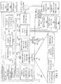
- FIG. 3 is a block diagram illustrating one example of a control system architecture 200 that can be used to control hydraulic valves 114 (shown in FIG. 1 ) in order to control the down force exerted by actuator 100 (or a set of actuators 100) on either individual row units or on gangs of row units, where a plurality of row units are ganged together.
- Architecture 200 thus includes a set of row units 202-204. It will be appreciated that each row unit 202-204 can actually be a gang of row units, all of which have a single actuator (or a set of actuators acting in common) to exert a downforce on the gang of row units. However, for the sake of the present discussion, each item 202-204 will be described as a single row unit, although this is only one example.
- Each row unit 202-204 includes (as discussed above with respect to FIG. 2 ) a gauge wheel load sensor 206-208, a downforce control valve 210-212, a downforce actuator 214-216, and it can include other items 218-220 (such as those shown in FIG. 2 ).
- Downforce actuators 214-216 are each, in one example, an actuator 100 shown in FIG. 1 .
- Control valves 210-212 are each illustratively a valve 114 (shown in FIG. 1 ). Thus they are controlled by downforce control system 222 so that they controllably provide fluid under pressure from hydraulic system 224 to the corresponding actuators 214-216, and allow hydraulic fluid to flow back to the tank of hydraulic system 224 from actuators 214-216.
- Architecture 200 is also shown with a set of other planting condition sensors 226.
- Other planting condition sensors 226 can sense a wide variety of conditions. For instance, they can sense soil moisture, soil compaction, the location or speed of the machine that is pulling the row units, or a wide variety of other sensors.
- Control system 222 can receive sensor signals from gauge wheel load sensors 206-208 and sensors 226 and use those signals to control valves 210-212 to control the downforce applied by downforce actuators 214-216.
- downforce control system 222 can operate according to a wide variety of different control algorithms. For instance, it can operate in a very precise, high resolution manner, that accomplishes millisecond (or better) control of valves 210-212, in order to control the force profile exerted by actuators 214-216. In other applications, it can operate with less resolution.
- FIG. 4 is a pictorial illustration (in section) of another example of actuator 100. Some items are similar to those shown in FIG. 1 , and they are similarly numbered. It can be seen in FIG. 4 that volume 108 is formed of the volume within guide 112, that guides rod 104. Piston 106 is annularly disposed about guide 112, and volume 108 ports over to the upper surface of piston 106 through space 250 at the top of guide 112. The accumulator volume 110 is illustratively charged through a pre-charge valve 252 in port 120. It will be noted, of course, that the illustration shown in FIG. 4 is only one example.
- the present actuator geometry provides a relatively large accumulator volume, relative to the hydraulic actuator volume.
- the accumulator volume 110 can be greatly increased. This allows the accumulator volume to be increased with relatively small increases in the outer diameter of actuator 100. This also enables the force profile of rod 104 to be relatively stable, or constant, without taking up a great deal of real estate on the implement to which it is attached (such as on a row unit or gang of row units).
- actuator 100 can be provided in a variety of other applications. For instance, it can be provided on a cab suspension assembly where it provides suspension of a cab on a mobile machine. It can be provided on a seat suspension assembly or in a wide variety of other applications.
- the hydraulic actuator is a single acting actuator.
- the hydraulic fluid pressure instead of providing hydraulic fluid under pressure to both extend and retract rod 104, the hydraulic fluid pressure only acts in one direction.
- the placement of the accumulator volume 110 can be changed as well. Instead of being concentrically arranged around guide 112 (and rod 104) it can be arranged within piston rod 104. In such an example, the accumulator volume 110 may not be as great as in the example where it is disposed annularly outside of rod 104, but it will also be within the enclosure of actuator 100 so that an external accumulator need not be provided. This still saves real estate on the row unit, while allowing a significant accumulator volume to be obtained.
- controllers, processors or servers include computer processors with associated memory and timing circuitry, not separately shown. They are functional parts of the systems or devices to which they belong and are activated by, and facilitate the functionality of the other components or items in those systems.
- FIG. 5 is one example of a computing environment in which the downforce control system 222 of the architecture in FIG. 3 , or parts of it, (for example) can be deployed.
- an example system for implementing some embodiments includes a general-purpose computing device in the form of a computer 810.
- Components of computer 810 may include, but are not limited to, a processing unit 820, a system memory 830, and a system bus 821 that couples various system components including the system memory to the processing unit 820.
- the system bus 821 may be any of several types of bus structures including a memory bus or memory controller, a peripheral bus, and a local bus using any of a variety of bus architectures. Memory and programs described with respect to FIG. 3 can be deployed in corresponding portions of FIG. 5 .
- Computer 810 typically includes a variety of computer readable media.
- Computer readable media can be any available media that can be accessed by computer 810 and includes both volatile and nonvolatile media, removable and non-removable media.
- Computer readable media may comprise computer storage media and communication media.
- Computer storage media is different from, and does not include, a modulated data signal or carrier wave. It includes hardware storage media including both volatile and nonvolatile, removable and non-removable media implemented in any method or technology for storage of information such as computer readable instructions, data structures, program modules or other data.
- Computer storage media includes, but is not limited to, RAM, ROM, EEPROM, flash memory or other memory technology, CD-ROM, digital versatile disks (DVD) or other optical disk storage, magnetic cassettes, magnetic tape, magnetic disk storage or other magnetic storage devices, or any other medium which can be used to store the desired information and which can be accessed by computer 810.
- Communication media may embody computer readable instructions, data structures, program modules or other data in a transport mechanism and includes any information delivery media.
- modulated data signal means a signal that has one or more of its characteristics set or changed in such a manner as to encode information in the signal.
- the system memory 830 includes computer storage media in the form of volatile and/or nonvolatile memory such as read only memory (ROM) 831 and random access memory (RAM) 832.
- ROM read only memory
- RAM random access memory
- BIOS basic input/output system 833
- RAM 832 typically contains data and/or program modules that are immediately accessible to and/or presently being operated on by processing unit 820.
- FIG. 5 illustrates operating system 834, application programs 835, other program modules 836, and program data 837.
- the computer 810 may also include other removable/non-removable volatile/nonvolatile computer storage media.
- FIG. 5 illustrates a hard disk drive 841 that reads from or writes to non-removable, nonvolatile magnetic media, an optical disk drive 855, and nonvolatile optical disk 856.
- the hard disk drive 841 is typically connected to the system bus 821 through a non-removable memory interface such as interface 840, and optical disk drive 855 are typically connected to the system bus 821 by a removable memory interface, such as interface 850.
- the functionality described herein can be performed, at least in part, by one or more hardware logic components.
- illustrative types of hardware logic components include Field-programmable Gate Arrays (FPGAs), Application-specific Integrated Circuits (e.g., ASICs), Application-specific Standard Products (e.g., ASSPs), System-on-a-chip systems (SOCs), Complex Programmable Logic Devices (CPLDs), etc.
- drives and their associated computer storage media discussed above and illustrated in FIG. 5 provide storage of computer readable instructions, data structures, program modules and other data for the computer 810.
- hard disk drive 841 is illustrated as storing operating system 844, application programs 845, other program modules 846, and program data 847. Note that these components can either be the same as or different from operating system 834, application programs 835, other program modules 836, and program data 837.
- a user may enter commands and information into the computer 810 through input devices such as a keyboard 862, a microphone 863, and a pointing device 861, such as a mouse, trackball or touch pad.
- Other input devices may include foot pedals, steeling wheels, levers, buttons, a joystick, game pad, satellite dish, scanner, or the like.
- These and other input devices are often connected to the processing unit 820 through a user input interface 860 that is coupled to the system bus, but may be connected by other interface and bus structures.
- a visual display 891 or other type of display device is also connected to the system bus 821 via an interface, such as a video interface 890.
- computers may also include other peripheral output devices such as speakers 897 and printer 896, which may be connected through an output peripheral interface 895.
- the computer 810 is operated in a networked environment using logical connections (such as a local area network - LAN, or wide area network WAN) to one or more remote computers, such as a remote computer 880.
- logical connections such as a local area network - LAN, or wide area network WAN
- remote computers such as a remote computer 880.
- the computer 810 When used in a LAN networking environment, the computer 810 is connected to the LAN 871 through a network interface or adapter 870. When used in a WAN networking environment, the computer 810 typically includes a modem 872 or other means for establishing communications over the WAN 873, such as the Internet. In a networked environment, program modules may be stored in a remote memory storage device. FIG. 5 illustrates, for example, that remote application programs 885 can reside on remote computer 880.
Landscapes
- Engineering & Computer Science (AREA)
- Life Sciences & Earth Sciences (AREA)
- Soil Sciences (AREA)
- Mechanical Engineering (AREA)
- General Engineering & Computer Science (AREA)
- Physics & Mathematics (AREA)
- Fluid Mechanics (AREA)
- Environmental Sciences (AREA)
- Fluid-Pressure Circuits (AREA)
- Fluid-Damping Devices (AREA)
- Supply Devices, Intensifiers, Converters, And Telemotors (AREA)
- Actuator (AREA)
- Vehicle Body Suspensions (AREA)
Abstract
Description
- The present description relates to a piston accumulator. More specifically, the present description relates to a piston accumulator that is integrated with a cylinder rod assembly.
- An accumulator allows a hydraulic cylinder rod to move without changing the volume of oil in the cylinder. The accumulator has an accumulator volume that is separated from the hydraulic cylinder volume. When the cylinder rod moves, without changing the amount of oil in the cylinder, a movable element moves to compress the accumulator volume and thus absorb and release energy. This tends to even out a force profile exerted by the hydraulic cylinder rod.
- There are a wide variety of different applications for an accumulator. For instance, on mobile machines, a piston accumulator can be used in a cab suspension cylinder. It can also be used in a seat suspension cylinder or in a wide variety of other applications.
- In one example, accumulators can be used in agricultural equipment in order to even out a downforce that is applied by the equipment on the ground that it is treating. For instance, row units on a planter follow the ground profile by using a combination of gauge wheels (to keep the row unit from sinking into the ground) and a downforce assembly that includes springs (which can be either mechanical, pneumatic, or a combination of the two) to push disk openers into the ground. Currently, downforce assemblies provide a relatively fixed downforce, which may or may not be adjustable, while planting. Because there is no dampening in the downforce assembly, row units that are moving over soil while planting tend to bounce after hitting a hard patch of soil. This can result in incorrect seed placement. The seeds can be at an incorrect depth, or the seeds can even be dropped on the surface of the ground, because the row units can bounce completely out of the ground.
- In some systems, an operator can address this by increasing the downforce on the row unit. However, depending upon the different types of soil conditions, this can actually be detrimental. For example, if the downforce is too high, the gauge wheels can compress the sides of the furrow too much so that the sidewalls are too hard. Also, the seed depth can be too great.
- Adding hardware to a row unit also presents some challenges. Row units can have a relatively large number of hardware components. Thus, packaging additional hardware components on an already crowded row unit, can be become difficult.
- The discussion above is merely provided for general background information and is not intended to be used as an aid in determining the scope of the claimed subject matter.
- A cylinder rod is disposed within a cylinder that defines a cylinder volume. An accumulator defines an accumulator volume that is disposed generally annularly about the cylinder rod. The accumulator volume is separated from the cylinder volume by an accumulator piston.
- This Summary is provided to introduce a selection of concepts in a simplified form that are further described below in the Detailed Description. This Summary is not intended to identify key features or essential features of the claimed subject matter, nor is it intended to be used as an aid in determining the scope of the claimed subject matter. The claimed subject matter is not limited to implementations that solve any or all disadvantages noted in the background.
-
-
FIG. 1 is a cross sectional view of one example of a piston accumulator. -
FIG. 2 is a pictorial illustration of one example of a row unit, with the piston accumulator (illustrated inFIG. 1 ) disposed thereon. -
FIG. 3 is a block diagram of one example of a downforce control system architecture. -
FIG. 4 is a more detailed illustration of one example of a piston accumulator integrated with a cylinder rod. -
FIG. 5 is a block diagram of one example of a computing environment that can be used in the control system architecture shown inFIG. 3 . -
FIG. 1 is a cross sectional view of one example of ahydraulic actuator 100.Actuator 100 illustratively includes a cylinder (or cylinder housing) 102 with a piston (or rod) 104. Actuator 100 also illustratively includes anaccumulator piston 106 that divides the volume withincylinder 102 into ahydraulic cylinder volume 108 and anaccumulator volume 110. In the example shown inFIG. 1 ,guide 112 serves as both a rod guide forrod 104 and a piston guide foraccumulator piston 106. It can thus be seen thataccumulator volume 110 is, in one example, generally annularly disposed about bothguide 112 androd 104. - In the example shown in
FIG. 1 ,actuator 100 is also provided with ahydraulic valve 114 that is coupled to a hydraulic system (shown inFIG. 4 ). Thus,valve 114 is illustratively controllable to provide hydraulic fluid under pressure from the hydraulic system, throughport 116, tovolume 108. This increases fluid pressure involume 108 and can thus causerod 104 to extend in the direction generally indicated byarrow 118. Valve 114 is also controllable to allow fluid to flow fromvolume 108 to a tank of the hydraulic system. This can allowrod 104 to move in a direction generally opposite that ofarrow 118. -
FIG. 1 also shows that, in one example,accumulator volume 110 can be accessed throughaccumulator port 120, which may have an accumulator valve (or precharge valve) disposed therein. Thus,volume 110 can be pre-charged with a desired amount of gas (or other compressible medium, that is more compressible than the hydraulic oil or other medium in cylinder volume 108) to fillaccumulator volume 110 to a desired pressure. Piston 106 can illustratively move up and down alongguide 112 between two extreme positions. One extreme position can define a maximum accumulator volume, while the other extreme position can define a minimum accumulator volume. The pre-change pressure can be a pre-defined pressure at maximum volume, at minimum volume, or both. - Also, in some examples,
actuator 100 can be provided with a set ofdampening components 122.Dampening components 122 can include one or more orifices, one or more one way orifices, relief valves, or other components. -
Actuator 100 illustratively includes one ormore mounting brackets 121.Actuator 100 is illustratively coupled to a frame of a machine that carries it withbracket 121. - In operation,
accumulator volume 110 can be pre-charged to the desired pre-charge pressure, or to a desired volume, through the pre-charge valve that resides incharge port 120. The amount of force applied onrod 104 in the direction indicated byarrow 118 is then controlled by introducing hydraulic fluid under pressure, throughvalve 114 andport 116, intovolume 108. This will increase the pressure involume 108 to simultaneously exert pressure onrod 104 and onaccumulator piston 106.Rod 104 will illustratively move in the direction indicated by arrow 118 (or at least apply force in that direction) whilepiston 106 compresses the gas involume 110. The amount of force being exerted byrod 104 on a work piece or another item that it is acting on, can be sensed, and when a desired force is reached, then the hydraulic fluid under pressure can simply be maintained at that pressure involume 108, such as byclosing valve 114. - It may be, however, that
rod 104 experiences a disturbance (or an applied force) in a direction oppositearrow 118. By way of example, in an implementation (which will be described in greater detail below) whererod 104 is being used to apply down force to a row unit on a planter, the row unit may hit a patch of dry ground. This may result in an upwardly directed force (in the direction opposite arrow 118) being applied torod 104. This will causerod 104 to move upwardly (in the direction opposite arrow 118). Meanwhile, the amount of hydraulic fluid involume 108 remains constant. Thus, movement ofrod 104 intovolume 108, in turn, causespiston 106 to compress the gas involume 110 and thus store energy. When the disturbance is removed fromrod 104, the gas involume 110 will again expand causingpiston 106 to move upwardly in the depiction illustrated inFIG. 1 , thus releasing the stored energy. This interaction tends to even out the force profile of the force exerted byrod 104. - It may be desired that, in order to keep the force profile relatively flat, the ratio of
volume 110 tovolume 108 may be relatively large. However, because row units have relatively restricted space, this can be difficult. It can be seen inFIG. 1 , however, that the geometry of disposingaccumulator volume 110 generally concentrically aboutrod 104 allows for the ratio ofaccumulator volume 110 tocylinder volume 108 to be relatively large. Because of the relationship between a change in the outer diameter ofcylinder 102 and a corresponding change in the size ofvolume 110, a relatively small change in the outer diameter ofcylinder 102 yields a relatively large change involume 110. Thus, the geometry illustrated inFIG. 1 allows theaccumulator volume 110 to be increased, by a large amount, in comparison to any corresponding increase in the size ofactuator 100. - It will also be noted that the operation of
actuator 100 can be tuned in a number of different ways. For instance, valves integrated as dampeningcomponents 122 can dampen the operation ofaccumulator piston 106. This can increase the linearity of the accumulator response. For instance, at high pressures incylinder volume 108, the resolution of the accumulator response ofpiston 106 tends to decrease. Therefore, in one example, dampeningcomponents 122 include a pressure-responsive valve. At higher pressures involume 108, the valve restricts the flow of fluids across dampeningcomponents 122. This tends to dampen the response ofaccumulator 106 more, at higher cylinder pressures involume 108. A wide variety of other dampeningcomponents 122 can be used in order to tune the accumulator response as well. - Further, the movement of
piston 106 may be limited by a positive stop (or a set of positive stops) disposed on the inner surface ofcylinder 102, or on the outer surface ofguide 112, or both. These define the extreme positions of thepiston 106 and thus define the maximum and minimum accumulator volumes. The placement of such positive stops can thus be used to tune the response ofaccumulator piston 106 as well. - Further, the gas pre-charge in
volume 110 can be used to tune the accumulator response. It may be assumed, in one example, thatpiston 106 is movable between two extremes so thatvolume 110 varies between the maximum volume and the minimum volume. By setting the gas pre-charge value involume 110 to be a given pressure at the maximum or minimum volumes, or both, this can change the response of the accumulator as well. - In addition, the control mechanism for controlling
valve 114 can be used to tune the accumulator response as well. Assume, first, that it is desired that the accumulator response be linear with respect to movement ofrod 104. That is, for every change in the position ofrod 104, there is a change in the position ofpiston 106, and the relationship between the two change values varies linearly over the operational pressures inhydraulic cylinder volume 108. Assume further that its operation is linear over a given percent of its operational pressure range. Then, in the non-linear areas, the control system used to controlvalve 114 can make adjustments to the hydraulic fluid pressure withinvolume 108, in order to further linearize the accumulator response and ultimately the force profile of the actuator. These, of course, are only examples of how the response of the accumulator can be tuned with respect to the example shown inFIG. 1 . -
FIG. 2 shows one example of an application ofactuator 100.FIG. 2 shows arow unit 130 on an agricultural planter.Row unit 130 is illustratively fastened to other row units bytool bar 148. The set of row units is illustratively towed behind a mobile machine, such as a tractor. -
Row unit 130 illustratively includes afertilizer tank 132 and aseed storage tank 134. It also illustratively includes adisk opener 136, a set ofgauge wheels 138, and a set of closingwheels 140. Seeds are illustratively dropped through aseed tube 142, fromseed storage tank 134. The seeds can be sensed by aseed sensor 144 and the rate at which seeds are dropped can be controlled usingseed meter 146.Actuator 100 is mounted on acoupling assembly 150 that couplesrow unit 130 totoolbar 148.Rod 104 is coupled to aparallel linkage 152 and is used to exert down force (in the direction indicated by arrow 154) onrow unit 130. The downforce is offset by the upwardly directed forces acting on closing wheels 140 (from ground 162) and double disk opener 136 (again from ground 162). The remaining force (the force vector indicated byarrow 154 minus the sum of the force vectors exerted ondouble disk opener 136 and closing wheels 140), is the differential force, and this force acts ongauge wheels 138. This load is sensed by a gauge wheel load sensor (shown inFIG. 4 ). - As
row unit 130 travels generally in the direction indicated byarrow 156, thedouble disk opener 136 opens a furrow in the soil, seeds are dropped throughseed tube 142, and closingwheels 140 close the soil.Gauge wheels 138 control the depth of the furrow and also act to firm the ground on the sides of the furrow so they do not collapse and re-fill the furrow before a seed is dropped into the furrow.Gauge wheel 138 can include the gauge wheel load sensor that senses the load exerted (generally indicated by arrow 160) on the gauge wheels. In one example, it may be desirable to keepgauge wheels 160 in constant contact with theground 162 over which rowunit 130 is traveling, but not to exert too much pressure so that they undesirably compact or otherwise affect the soil. - However, when
double disk opener 136 hits a hard patch of ground (for instance), it may move upward. This can impart an upwardly-directed force onrod 104, as discussed above with respect toFIG. 1 . Upward movement ofrod 104 acts to momentarily increase the pressure involume 108. In that case, accumulator piston 106 (shown inFIG. 1 ) will compress theaccumulator volume 110 to absorb (or store) the energy imparted by that force. When the force onrod 104 is removed,piston 106 releases the stored energy. This tends to smooth out the force profile of the downforce exerted by actuator 100 (and rod 104) in the direction indicated byarrow 154. -
FIG. 3 is a block diagram illustrating one example of acontrol system architecture 200 that can be used to control hydraulic valves 114 (shown inFIG. 1 ) in order to control the down force exerted by actuator 100 (or a set of actuators 100) on either individual row units or on gangs of row units, where a plurality of row units are ganged together.Architecture 200 thus includes a set of row units 202-204. It will be appreciated that each row unit 202-204 can actually be a gang of row units, all of which have a single actuator (or a set of actuators acting in common) to exert a downforce on the gang of row units. However, for the sake of the present discussion, each item 202-204 will be described as a single row unit, although this is only one example. - Each row unit 202-204 includes (as discussed above with respect to
FIG. 2 ) a gauge wheel load sensor 206-208, a downforce control valve 210-212, a downforce actuator 214-216, and it can include other items 218-220 (such as those shown inFIG. 2 ). Downforce actuators 214-216 are each, in one example, anactuator 100 shown inFIG. 1 . - Control valves 210-212 are each illustratively a valve 114 (shown in
FIG. 1 ). Thus they are controlled bydownforce control system 222 so that they controllably provide fluid under pressure fromhydraulic system 224 to the corresponding actuators 214-216, and allow hydraulic fluid to flow back to the tank ofhydraulic system 224 from actuators 214-216. -
Architecture 200 is also shown with a set of otherplanting condition sensors 226. Otherplanting condition sensors 226 can sense a wide variety of conditions. For instance, they can sense soil moisture, soil compaction, the location or speed of the machine that is pulling the row units, or a wide variety of other sensors.Control system 222 can receive sensor signals from gauge wheel load sensors 206-208 andsensors 226 and use those signals to control valves 210-212 to control the downforce applied by downforce actuators 214-216. - It should be noted that
downforce control system 222 can operate according to a wide variety of different control algorithms. For instance, it can operate in a very precise, high resolution manner, that accomplishes millisecond (or better) control of valves 210-212, in order to control the force profile exerted by actuators 214-216. In other applications, it can operate with less resolution. -
FIG. 4 is a pictorial illustration (in section) of another example ofactuator 100. Some items are similar to those shown inFIG. 1 , and they are similarly numbered. It can be seen inFIG. 4 thatvolume 108 is formed of the volume withinguide 112, that guidesrod 104.Piston 106 is annularly disposed aboutguide 112, andvolume 108 ports over to the upper surface ofpiston 106 throughspace 250 at the top ofguide 112. Theaccumulator volume 110 is illustratively charged through apre-charge valve 252 inport 120. It will be noted, of course, that the illustration shown inFIG. 4 is only one example. - It can thus be seen that the present actuator geometry provides a relatively large accumulator volume, relative to the hydraulic actuator volume. By even slightly increasing the diameter of
cylinder 102, theaccumulator volume 110 can be greatly increased. This allows the accumulator volume to be increased with relatively small increases in the outer diameter ofactuator 100. This also enables the force profile ofrod 104 to be relatively stable, or constant, without taking up a great deal of real estate on the implement to which it is attached (such as on a row unit or gang of row units). - It will also be noted that
actuator 100 can be provided in a variety of other applications. For instance, it can be provided on a cab suspension assembly where it provides suspension of a cab on a mobile machine. It can be provided on a seat suspension assembly or in a wide variety of other applications. - It should also be noted that, in one example, the hydraulic actuator is a single acting actuator. Thus, instead of providing hydraulic fluid under pressure to both extend and retract
rod 104, the hydraulic fluid pressure only acts in one direction. - Similarly, it will be noted that the placement of the
accumulator volume 110 can be changed as well. Instead of being concentrically arranged around guide 112 (and rod 104) it can be arranged withinpiston rod 104. In such an example, theaccumulator volume 110 may not be as great as in the example where it is disposed annularly outside ofrod 104, but it will also be within the enclosure ofactuator 100 so that an external accumulator need not be provided. This still saves real estate on the row unit, while allowing a significant accumulator volume to be obtained. - The present discussion has mentioned controllers, processors or servers. In one example, the controllers, processors or servers include computer processors with associated memory and timing circuitry, not separately shown. They are functional parts of the systems or devices to which they belong and are activated by, and facilitate the functionality of the other components or items in those systems.
-
FIG. 5 is one example of a computing environment in which thedownforce control system 222 of the architecture inFIG. 3 , or parts of it, (for example) can be deployed. With reference toFIG. 5 , an example system for implementing some embodiments includes a general-purpose computing device in the form of acomputer 810. Components ofcomputer 810 may include, but are not limited to, aprocessing unit 820, asystem memory 830, and asystem bus 821 that couples various system components including the system memory to theprocessing unit 820. Thesystem bus 821 may be any of several types of bus structures including a memory bus or memory controller, a peripheral bus, and a local bus using any of a variety of bus architectures. Memory and programs described with respect toFIG. 3 can be deployed in corresponding portions ofFIG. 5 . -
Computer 810 typically includes a variety of computer readable media. Computer readable media can be any available media that can be accessed bycomputer 810 and includes both volatile and nonvolatile media, removable and non-removable media. By way of example, and not limitation, computer readable media may comprise computer storage media and communication media. Computer storage media is different from, and does not include, a modulated data signal or carrier wave. It includes hardware storage media including both volatile and nonvolatile, removable and non-removable media implemented in any method or technology for storage of information such as computer readable instructions, data structures, program modules or other data. Computer storage media includes, but is not limited to, RAM, ROM, EEPROM, flash memory or other memory technology, CD-ROM, digital versatile disks (DVD) or other optical disk storage, magnetic cassettes, magnetic tape, magnetic disk storage or other magnetic storage devices, or any other medium which can be used to store the desired information and which can be accessed bycomputer 810. Communication media may embody computer readable instructions, data structures, program modules or other data in a transport mechanism and includes any information delivery media. The term "modulated data signal" means a signal that has one or more of its characteristics set or changed in such a manner as to encode information in the signal. - The
system memory 830 includes computer storage media in the form of volatile and/or nonvolatile memory such as read only memory (ROM) 831 and random access memory (RAM) 832. A basic input/output system 833 (BIOS), containing the basic routines that help to transfer information between elements withincomputer 810, such as during start-up, is typically stored inROM 831.RAM 832 typically contains data and/or program modules that are immediately accessible to and/or presently being operated on by processingunit 820. By way of example, and not limitation,FIG. 5 illustratesoperating system 834,application programs 835,other program modules 836, andprogram data 837. - The
computer 810 may also include other removable/non-removable volatile/nonvolatile computer storage media. By way of example only,FIG. 5 illustrates ahard disk drive 841 that reads from or writes to non-removable, nonvolatile magnetic media, anoptical disk drive 855, and nonvolatileoptical disk 856. Thehard disk drive 841 is typically connected to thesystem bus 821 through a non-removable memory interface such asinterface 840, andoptical disk drive 855 are typically connected to thesystem bus 821 by a removable memory interface, such asinterface 850. - Alternatively, or in addition, the functionality described herein can be performed, at least in part, by one or more hardware logic components. For example, and without limitation, illustrative types of hardware logic components that can be used include Field-programmable Gate Arrays (FPGAs), Application-specific Integrated Circuits (e.g., ASICs), Application-specific Standard Products (e.g., ASSPs), System-on-a-chip systems (SOCs), Complex Programmable Logic Devices (CPLDs), etc.
- The drives and their associated computer storage media discussed above and illustrated in
FIG. 5 , provide storage of computer readable instructions, data structures, program modules and other data for thecomputer 810. InFIG. 5 , for example,hard disk drive 841 is illustrated as storingoperating system 844,application programs 845,other program modules 846, andprogram data 847. Note that these components can either be the same as or different fromoperating system 834,application programs 835,other program modules 836, andprogram data 837. - A user may enter commands and information into the
computer 810 through input devices such as akeyboard 862, amicrophone 863, and apointing device 861, such as a mouse, trackball or touch pad. Other input devices (not shown) may include foot pedals, steeling wheels, levers, buttons, a joystick, game pad, satellite dish, scanner, or the like. These and other input devices are often connected to theprocessing unit 820 through auser input interface 860 that is coupled to the system bus, but may be connected by other interface and bus structures. Avisual display 891 or other type of display device is also connected to thesystem bus 821 via an interface, such as avideo interface 890. In addition to the monitor, computers may also include other peripheral output devices such asspeakers 897 andprinter 896, which may be connected through an outputperipheral interface 895. - The
computer 810 is operated in a networked environment using logical connections (such as a local area network - LAN, or wide area network WAN) to one or more remote computers, such as aremote computer 880. - When used in a LAN networking environment, the
computer 810 is connected to theLAN 871 through a network interface or adapter 870. When used in a WAN networking environment, thecomputer 810 typically includes amodem 872 or other means for establishing communications over theWAN 873, such as the Internet. In a networked environment, program modules may be stored in a remote memory storage device.FIG. 5 illustrates, for example, thatremote application programs 885 can reside onremote computer 880. - It should also be noted that the different embodiments described herein can be combined in different ways. That is, parts of one or more embodiments can be combined with parts of one or more other embodiments. All of this is contemplated herein.
Claims (12)
- An actuator (100, 214 -216), comprising:a rod (104);a cylinder housing (102) defining a cylinder volume (108) and an accumulator volume (110), the cylinder housing (102) movably supporting the rod (104) for movement outward relative to the cylinder housing (102) in response to fluid under pressure being introduced into the cylinder volume (108); andan accumulator piston (106), movably supported within the cylinder housing (102) and separating the cylinder volume (108) from the accumulator volume (110) in the cylinder housing (102), characterized in that the cylinder housing (102) defines the accumulator volume (110) generally about an outer periphery of the rod (104), wherein the cylinder housing (102) comprises a guide that has an inner surface and an outer surface and supports the rod (104) for movement along the inner surface.
- The actuator (100, 214 -216) of claim 1 wherein the guide supports the accumulator piston (106) for movement along the outer surface of the guide.
- The actuator (100, 214 -216) of claim 1 or 2 wherein the cylinder housing (102) defines the accumulator volume (110) generally concentrically about the outer surface of the guide.
- The actuator (100, 214 -216) of one of the claims 1 to 3 wherein the accumulator volume (110) is charged with a compressible medium and wherein the accumulator piston (106) moves to compress the compressible medium in the accumulator volume (110) in response to movement of the rod (104) into the cylinder housing (102) with constant fluid under pressure in the cylinder volume (108).
- The actuator (100, 214 -216) of one of the claims 1 to 4 and further comprising:a dampening component (122) mounted within the inner surface of the guide to dampen an accumulator response to movement of the rod (104) inward relative to the cylinder housing (102) with a constant cylinder volume (108).
- The actuator (100, 214 -216) of one of the claims 1 to 5 wherein the cylinder housing (102) comprises a hydraulic actuator housing and wherein the fluid under pressure comprises hydraulic fluid.
- The actuator (100, 214 -216) of one of the claims 1 to 6 wherein the accumulator piston (106) is slidably mounted to reduce the accumulator volume (110) when the rod (104) moves inward relative to the cylinder housing (102) with a constant cylinder volume.
- The actuator (100, 214 -216) of one of the claims 5 to 7, wherein the dampening component (122) comprises:a restrictor that restricts flow of the fluid in the cylinder volume (108) thereacross.
- A row unit (130) for performing an operation on a crop row, the row unit (130) comprising:a soil engaging element that engages soil to perform the operation; characterized in further comprising:a downforce actuator that applies a down force to the soil engaging element, the downforce actuator comprising an actuator (100, 214 -216) as claimed in one of the claims 1 to 8.
- The row unit (130) of claim 9, wherein the soil engaging element comprises:an opener (136) that generates a furrow in the soil to receive a seed;a closer (140) that closes the furrow; anda set of gauge wheels (138) that control a depth of the furrow and that firm sides of the furrow.
- The row unit (130) of claim 9 or 10 and further comprising:a gauge wheel load sensor (206 - 208) that senses a load on the set of gauge wheels (138) and generates a sensor signal indicative of the sensed load, and wherein a control system (222) receives the sensor signal and controls the fluid under pressure to the downforce actuator based on the sensor signal.
- The row unit (130) of one of the claims 9 to 11, wherein the downforce actuator provides the downforce to a plurality of ganged row units (202 -204).
Applications Claiming Priority (1)
| Application Number | Priority Date | Filing Date | Title |
|---|---|---|---|
| US14/843,293 US9964124B2 (en) | 2015-09-02 | 2015-09-02 | Piston accumulator with integrated cylinder rod |
Publications (1)
| Publication Number | Publication Date |
|---|---|
| EP3138374A1 true EP3138374A1 (en) | 2017-03-08 |
Family
ID=56888944
Family Applications (1)
| Application Number | Title | Priority Date | Filing Date |
|---|---|---|---|
| EP16186798.1A Withdrawn EP3138374A1 (en) | 2015-09-02 | 2016-09-01 | Actuator and agricultural row unit comprising the same |
Country Status (4)
| Country | Link |
|---|---|
| US (1) | US9964124B2 (en) |
| EP (1) | EP3138374A1 (en) |
| BR (1) | BR102016020169B1 (en) |
| CA (1) | CA2938246C (en) |
Families Citing this family (23)
| Publication number | Priority date | Publication date | Assignee | Title |
|---|---|---|---|---|
| US10912246B2 (en) | 2018-07-19 | 2021-02-09 | Cnh Industrial Canada, Ltd. | System for controlling the operation of an actuator mounted on a seed planting implement |
| CN109005773B (en) * | 2018-08-13 | 2021-11-23 | 衡阳市绿荫生态农业有限公司 | A novel fruit growing ditching machine for loosening soil before planting |
| USD985673S1 (en) | 2018-11-14 | 2023-05-09 | Aristocrat Technologies Australia Pty Limited | Gaming machine display |
| US11701594B2 (en) * | 2019-04-16 | 2023-07-18 | Aristocrat Technologies Australia Pty Limited | Overhead display having concentric inner and outer displays and associated systems and methods |
| CN112944016A (en) * | 2019-12-10 | 2021-06-11 | 中核苏阀科技实业股份有限公司 | Oil cylinder accumulator assembly of large-scale complex gas-liquid linkage driving device |
| US11553638B2 (en) | 2019-12-24 | 2023-01-17 | Cnh Industrial America Llc | Particle delivery system of an agricultural row unit |
| US11490558B2 (en) | 2019-12-24 | 2022-11-08 | Cnh Industrial America Llc | Particle delivery system of an agricultural row unit |
| US11553639B2 (en) | 2019-12-24 | 2023-01-17 | Cnh Industrial America Llc | Particle delivery system of an agricultural row unit |
| US11564344B2 (en) | 2019-12-24 | 2023-01-31 | Cnh Industrial America Llc | Particle delivery system of an agricultural row unit |
| US11564346B2 (en) | 2019-12-24 | 2023-01-31 | Cnh Industrial America Llc | Particle delivery system of an agricultural row unit |
| US11516958B2 (en) | 2019-12-24 | 2022-12-06 | Cnh Industrial America Llc | Particle delivery system of an agricultural row unit |
| US11523555B2 (en) | 2019-12-24 | 2022-12-13 | Cnh Industrial America Llc | Particle delivery system of an agricultural row unit |
| US11589500B2 (en) | 2019-12-24 | 2023-02-28 | Cnh Industrial America Llc | Particle delivery system of an agricultural row unit |
| US11582899B2 (en) | 2019-12-24 | 2023-02-21 | Cnh Industrial America Llc | Particle delivery system of an agricultural row unit |
| US11596095B2 (en) | 2019-12-24 | 2023-03-07 | Cnh Industrial America Llc | Particle delivery system of an agricultural row unit |
| US11523556B2 (en) | 2019-12-24 | 2022-12-13 | Cnh Industrial America Llc | Particle delivery system of an agricultural row unit |
| US11483963B2 (en) | 2019-12-24 | 2022-11-01 | Cnh Industrial America Llc | Particle delivery system of an agricultural row unit |
| CN111316793B (en) * | 2020-03-03 | 2020-12-25 | 广东省农业科学院 | Efficient automatic seeding device |
| CN112628236A (en) * | 2020-12-16 | 2021-04-09 | 宁波盛德气动液压有限公司 | Hydraulic cylinder dust-adhering prevention device for supplementing auxiliary hydraulic oil by utilizing self movement |
| CN112762028B (en) * | 2021-01-18 | 2022-07-05 | 国家石油天然气管网集团有限公司华南分公司 | Voltage-stabilizing closed oil tank |
| US12031556B2 (en) * | 2021-09-30 | 2024-07-09 | Deere & Company | Dual gas pressure accumulator system |
| EP4542055A4 (en) * | 2022-06-17 | 2026-03-11 | Eagle Ind Co Ltd | PRESSURE OVERLOAD DEVICE |
| WO2024020287A1 (en) * | 2022-07-18 | 2024-01-25 | Parker-Hannifin Corporation | Actuator for ground engaging machinery |
Citations (7)
| Publication number | Priority date | Publication date | Assignee | Title |
|---|---|---|---|---|
| JPS62121402U (en) * | 1986-01-24 | 1987-08-01 | ||
| FR2823803A1 (en) * | 2001-04-23 | 2002-10-25 | Valeo | Hydraulic actuator for e.g. vehicle clutch, includes constant delivery pump with outlet opening connected to actuator chamber and accumulator |
| EP1703142A1 (en) * | 2005-03-15 | 2006-09-20 | Deere & Company | Hydraulic cylinder with integrated accumulator |
| FR2894303A1 (en) * | 2005-12-02 | 2007-06-08 | Pommier S C E B P Sa | Shock-absorbing hydraulic cylinder is divided into narrow chamber and wide chamber by peripheral shoulder, piston of smaller diameter than narrow chamber being mounted in slide which fits closely in wider chamber |
| EP2554036A1 (en) * | 2011-08-01 | 2013-02-06 | Deere & Company | A supplemental down force system and ground working implement with same |
| DE102011121777A1 (en) * | 2011-12-21 | 2013-06-27 | Ewo Fluid Power Gmbh | Double-acting hydraulic cylinder for use as vibration damper in active hydropneumatic suspension system in motor car, has connecting lines arranged within cylinder and connecting pressure chambers with storage chambers of accumulators |
| US20150208571A1 (en) * | 2014-01-24 | 2015-07-30 | Kinze Manufacturing, Inc. | Agricultural implement with electro-hydraulic cylinders |
Family Cites Families (26)
| Publication number | Priority date | Publication date | Assignee | Title |
|---|---|---|---|---|
| US2546648A (en) * | 1948-09-30 | 1951-03-27 | Greer Hydraulics Inc | Spring controlled guide rod for the oil port valve of an accumulator |
| US3353352A (en) * | 1966-01-11 | 1967-11-21 | Caterpillar Tractor Co | Load balancing system for hydraulic jack |
| DE1954604A1 (en) * | 1969-10-30 | 1971-05-13 | Deere & Co | Lifting and lowering device, especially for work equipment that can be connected to a vehicle, for example for the mower assembly of combine harvesters |
| US3869861A (en) * | 1973-10-15 | 1975-03-11 | Hesston Corp | Combination hydraulic cylinder and accumulator |
| US4074858A (en) * | 1976-11-01 | 1978-02-21 | Institute Of Gas Technology | High pressure pulsed water jet apparatus and process |
| CH672615A5 (en) * | 1987-02-12 | 1989-12-15 | Walter Baiker Dipl Ing | |
| FR2617545B1 (en) * | 1987-07-03 | 1993-04-30 | Applic Mach Motrices | HYDROPNEUMATIC CYLINDER |
| US5234060A (en) * | 1992-02-21 | 1993-08-10 | The United States Of America As Represnted By The Secretary Of Agriculture | Pressure and depth control in agricultural implement |
| JP2985707B2 (en) * | 1995-01-31 | 1999-12-06 | トヨタ自動車株式会社 | Self-pumping shock absorber |
| GB2313646B (en) * | 1996-05-28 | 2000-04-26 | Fichtel & Sachs Ag | Self-pumping hydropneumatic suspension strut with internal levelling |
| JP3347597B2 (en) * | 1996-08-07 | 2002-11-20 | ヤマハ発動機株式会社 | Vehicle suspension |
| US6263556B1 (en) * | 1999-10-27 | 2001-07-24 | Ford Global Technologies, Inc. | Temperature compensating gas spring strut and method of making |
| JP2001180245A (en) * | 1999-12-24 | 2001-07-03 | Yamaha Motor Co Ltd | Vehicle suspension |
| DE10139192A1 (en) * | 2001-08-16 | 2003-03-06 | Hydac Technology Gmbh | piston accumulators |
| FR2831226B1 (en) * | 2001-10-24 | 2005-09-23 | Snecma Moteurs | AUTONOMOUS ELECTROHYDRAULIC ACTUATOR |
| DE10221833B4 (en) * | 2002-05-16 | 2006-03-09 | Zf Sachs Ag | Self-pumping hydropneumatic strut |
| JP3852701B2 (en) * | 2003-10-28 | 2006-12-06 | 株式会社小松製作所 | Hydraulic circuit using hydraulic cylinder |
| DE102005038115A1 (en) * | 2005-06-16 | 2006-12-28 | Stabilus Gmbh | gas spring |
| DE102005057639A1 (en) | 2005-12-02 | 2007-11-15 | Zf Lenksysteme Gmbh | toothed belt drive |
| WO2008157327A1 (en) * | 2007-06-14 | 2008-12-24 | Hybra-Drive Systems, Llc | Compact hydraulic accumulator |
| CN201615406U (en) | 2010-01-08 | 2010-10-27 | 李雄飞 | Photoflood lamp |
| US9232687B2 (en) * | 2010-09-15 | 2016-01-12 | Dawn Equipment Company | Agricultural systems |
| CN102041981A (en) | 2011-01-21 | 2011-05-04 | 钱雪松 | Sheathed oil well balancer |
| DE102011119011A1 (en) * | 2011-11-14 | 2013-05-16 | Hydac Technology Gmbh | Gas cylinder, in particular high-pressure gas cylinder |
| US9890681B2 (en) * | 2013-07-25 | 2018-02-13 | Yutaka Giken Co., Ltd. | Heat exchange device with thermoactuator |
| DE102013227053B4 (en) * | 2013-12-23 | 2023-04-20 | Robert Bosch Gmbh | hydraulic axis |
-
2015
- 2015-09-02 US US14/843,293 patent/US9964124B2/en active Active
-
2016
- 2016-08-08 CA CA2938246A patent/CA2938246C/en active Active
- 2016-08-31 BR BR102016020169-1A patent/BR102016020169B1/en active IP Right Grant
- 2016-09-01 EP EP16186798.1A patent/EP3138374A1/en not_active Withdrawn
Patent Citations (7)
| Publication number | Priority date | Publication date | Assignee | Title |
|---|---|---|---|---|
| JPS62121402U (en) * | 1986-01-24 | 1987-08-01 | ||
| FR2823803A1 (en) * | 2001-04-23 | 2002-10-25 | Valeo | Hydraulic actuator for e.g. vehicle clutch, includes constant delivery pump with outlet opening connected to actuator chamber and accumulator |
| EP1703142A1 (en) * | 2005-03-15 | 2006-09-20 | Deere & Company | Hydraulic cylinder with integrated accumulator |
| FR2894303A1 (en) * | 2005-12-02 | 2007-06-08 | Pommier S C E B P Sa | Shock-absorbing hydraulic cylinder is divided into narrow chamber and wide chamber by peripheral shoulder, piston of smaller diameter than narrow chamber being mounted in slide which fits closely in wider chamber |
| EP2554036A1 (en) * | 2011-08-01 | 2013-02-06 | Deere & Company | A supplemental down force system and ground working implement with same |
| DE102011121777A1 (en) * | 2011-12-21 | 2013-06-27 | Ewo Fluid Power Gmbh | Double-acting hydraulic cylinder for use as vibration damper in active hydropneumatic suspension system in motor car, has connecting lines arranged within cylinder and connecting pressure chambers with storage chambers of accumulators |
| US20150208571A1 (en) * | 2014-01-24 | 2015-07-30 | Kinze Manufacturing, Inc. | Agricultural implement with electro-hydraulic cylinders |
Also Published As
| Publication number | Publication date |
|---|---|
| CA2938246C (en) | 2025-05-06 |
| US9964124B2 (en) | 2018-05-08 |
| BR102016020169B1 (en) | 2022-10-18 |
| US20170058918A1 (en) | 2017-03-02 |
| CA2938246A1 (en) | 2017-03-02 |
| BR102016020169A2 (en) | 2017-03-07 |
Similar Documents
| Publication | Publication Date | Title |
|---|---|---|
| US9964124B2 (en) | Piston accumulator with integrated cylinder rod | |
| US10091926B2 (en) | Downforce sensing and control with acceleration correction | |
| US20220369539A1 (en) | Air seeder press wheel and closing wheel force control | |
| US9883626B2 (en) | Controlling an agricultural vehicle based on sensed inputs | |
| US11617295B2 (en) | Dynamic supplemental downforce control system for planter row units | |
| EP3469870B1 (en) | A planting depth control system for a planter row unit | |
| US11140812B2 (en) | Systems, methods, and apparatus for controlling downforce of an agricultural implement | |
| US9681601B2 (en) | Hydraulic cylinder for an agricultural row unit having an uplift accumulator and a down pressure accumulator | |
| US10251333B2 (en) | Agricultural system | |
| US10219421B2 (en) | Down and/or up force adjustment system | |
| US10827663B2 (en) | Actuator for setting a seed depth for a row unit on a planter | |
| Strasser et al. | Development of a test stand to quantify the response of a planter’s automatic downforce control system | |
| US20240090366A1 (en) | Seeder depth control | |
| BR102016022775B1 (en) | CONTROL SYSTEM FOR CONTROLLING AN AGRICULTURAL MACHINE, METHOD FOR CONTROLLING A TOWING VEHICLE, AND, AGRICULTURAL MACHINE |
Legal Events
| Date | Code | Title | Description |
|---|---|---|---|
| PUAI | Public reference made under article 153(3) epc to a published international application that has entered the european phase |
Free format text: ORIGINAL CODE: 0009012 |
|
| AK | Designated contracting states |
Kind code of ref document: A1 Designated state(s): AL AT BE BG CH CY CZ DE DK EE ES FI FR GB GR HR HU IE IS IT LI LT LU LV MC MK MT NL NO PL PT RO RS SE SI SK SM TR |
|
| AX | Request for extension of the european patent |
Extension state: BA ME |
|
| 17P | Request for examination filed |
Effective date: 20170908 |
|
| RBV | Designated contracting states (corrected) |
Designated state(s): AL AT BE BG CH CY CZ DE DK EE ES FI FR GB GR HR HU IE IS IT LI LT LU LV MC MK MT NL NO PL PT RO RS SE SI SK SM TR |
|
| STAA | Information on the status of an ep patent application or granted ep patent |
Free format text: STATUS: THE APPLICATION IS DEEMED TO BE WITHDRAWN |
|
| 18D | Application deemed to be withdrawn |
Effective date: 20170909 |