EP3138187B1 - Parameterizable power supply - Google Patents
Parameterizable power supply Download PDFInfo
- Publication number
- EP3138187B1 EP3138187B1 EP15721600.3A EP15721600A EP3138187B1 EP 3138187 B1 EP3138187 B1 EP 3138187B1 EP 15721600 A EP15721600 A EP 15721600A EP 3138187 B1 EP3138187 B1 EP 3138187B1
- Authority
- EP
- European Patent Office
- Prior art keywords
- output
- supply device
- output characteristic
- energy supply
- current
- Prior art date
- Legal status (The legal status is an assumption and is not a legal conclusion. Google has not performed a legal analysis and makes no representation as to the accuracy of the status listed.)
- Active
Links
- 238000004891 communication Methods 0.000 claims description 93
- 238000007600 charging Methods 0.000 claims description 26
- 238000000034 method Methods 0.000 claims description 19
- 208000031361 Hiccup Diseases 0.000 claims description 14
- 230000033228 biological regulation Effects 0.000 claims description 9
- 230000007423 decrease Effects 0.000 claims description 7
- 230000008859 change Effects 0.000 claims description 3
- RWSOTUBLDIXVET-UHFFFAOYSA-N Dihydrogen sulfide Chemical compound S RWSOTUBLDIXVET-UHFFFAOYSA-N 0.000 claims description 2
- 230000003247 decreasing effect Effects 0.000 claims 1
- 230000008901 benefit Effects 0.000 description 19
- 238000010586 diagram Methods 0.000 description 16
- 125000004122 cyclic group Chemical group 0.000 description 4
- 230000001413 cellular effect Effects 0.000 description 2
- 238000010277 constant-current charging Methods 0.000 description 2
- 238000010295 mobile communication Methods 0.000 description 2
- 230000036962 time dependent Effects 0.000 description 2
- 239000002253 acid Substances 0.000 description 1
- 230000006399 behavior Effects 0.000 description 1
- 230000005540 biological transmission Effects 0.000 description 1
- 239000004020 conductor Substances 0.000 description 1
- 238000010280 constant potential charging Methods 0.000 description 1
- 230000001419 dependent effect Effects 0.000 description 1
- 238000013461 design Methods 0.000 description 1
- 238000001514 detection method Methods 0.000 description 1
- 230000000694 effects Effects 0.000 description 1
- 230000006870 function Effects 0.000 description 1
- 230000036541 health Effects 0.000 description 1
- 238000002955 isolation Methods 0.000 description 1
- 238000012544 monitoring process Methods 0.000 description 1
- 238000004806 packaging method and process Methods 0.000 description 1
- 230000008569 process Effects 0.000 description 1
- 238000012546 transfer Methods 0.000 description 1
Images


Classifications
-
- H—ELECTRICITY
- H02—GENERATION; CONVERSION OR DISTRIBUTION OF ELECTRIC POWER
- H02M—APPARATUS FOR CONVERSION BETWEEN AC AND AC, BETWEEN AC AND DC, OR BETWEEN DC AND DC, AND FOR USE WITH MAINS OR SIMILAR POWER SUPPLY SYSTEMS; CONVERSION OF DC OR AC INPUT POWER INTO SURGE OUTPUT POWER; CONTROL OR REGULATION THEREOF
- H02M1/00—Details of apparatus for conversion
-
- G—PHYSICS
- G05—CONTROLLING; REGULATING
- G05B—CONTROL OR REGULATING SYSTEMS IN GENERAL; FUNCTIONAL ELEMENTS OF SUCH SYSTEMS; MONITORING OR TESTING ARRANGEMENTS FOR SUCH SYSTEMS OR ELEMENTS
- G05B15/00—Systems controlled by a computer
- G05B15/02—Systems controlled by a computer electric
-
- H—ELECTRICITY
- H02—GENERATION; CONVERSION OR DISTRIBUTION OF ELECTRIC POWER
- H02J—CIRCUIT ARRANGEMENTS OR SYSTEMS FOR SUPPLYING OR DISTRIBUTING ELECTRIC POWER; SYSTEMS FOR STORING ELECTRIC ENERGY
- H02J13/00—Circuit arrangements for providing remote indication of network conditions, e.g. an instantaneous record of the open or closed condition of each circuitbreaker in the network; Circuit arrangements for providing remote control of switching means in a power distribution network, e.g. switching in and out of current consumers by using a pulse code signal carried by the network
Definitions
- the present invention relates to the parameterization of an energy supply device.
- a parameterizable energy supply device such as a universal voltage supply device or a universal power supply device, often has a predetermined, non-adjustable output characteristic, for example a voltage-current output characteristic. If the energy supply device is designed as a universal voltage supply device, for example, an amplitude value of an output voltage of the parameterizable energy supply device can often be set, but not the amplitude value of the corresponding output current and thus the voltage-current output characteristic of the parameterizable energy supply device.
- the pamphlet KR 2011 0029381 A1 discloses remotely controllable power supplies in a consumption metering system.
- the pamphlet U.S. 2012/266007 A1 discloses an IT power supply.
- the pamphlet EP 1 775 821 A1 discloses a device for configuring the operating behavior of a charging device for accumulators, in which the required parameter values, such as charging current, charging voltage, charging duration and the like can be set via a user interface using a computing unit for general purposes.
- the pamphlet DE 10 2012 010487 A1 discloses an apparatus for evaluating a state of health of a battery.
- the pamphlet DE 199 54 583 A1 discloses a method for adjusting a heater control.
- the object is achieved by a parameterizable energy supply device according to claim 1.
- a parameterizable energy supply device can be provided with an adjustable output characteristic.
- the energy supply device that can be parameterized can be an electrical energy supply device, such as a voltage supply device or a power supply device, which has at least one adjustable output characteristic.
- the parameterizable energy supply device can include an electronically adjustable potentiometer for setting an amplitude value of an output voltage or an output current of the parameterizable energy supply device.
- the communication interface can include a wired and/or a wireless communication interface.
- the communication interface can include a wired and/or a wireless communication interface.
- Communication interface a serial interface, an interface based on the Power Management Bus (PMBus) standard, an interface based on the Universal Serial Bus (USB) standard, an interface for wireless communication using Radio Frequency Identification (RFID), for example based on the ISO/ IEC 14443 or ISO/IEC 18000-3, an interface for wireless communication using Near Field Communication (NFC), for example according to the ISO/IEC 14443 or ISO/IEC 18092 standard, or an interface for wireless communication according to one of the Bluetooth standards , ZigBee or Wireless Local Area Network (W-LAN).
- the communication network can be a telephone network, a cellular network, a computer network, for example a local area network (LAN) or a wireless local area network (W-LAN), or the Internet.
- LAN local area network
- WLAN wireless local area network
- the output characteristic can be a voltage-current output characteristic of the parameterizable energy supply device.
- the parameterization data can characterize or include an output characteristic or an output characteristic parameter of an output characteristic.
- the processor can be designed to set the output characteristic by selecting a pre-stored output characteristic and/or by setting an output characteristic parameter of the output characteristic.
- the processor can be designed to check the received parameterization data for validity. For example, the parameterization data are checked for validity using a cyclic redundancy check, for example according to the Cyclic Redundancy Check 8 (CRC-8) standard.
- CRC-8 Cyclic Redundancy Check 8
- the processor is designed to select the output characteristic from a plurality of pre-stored output characteristics on the basis of the received parameterization data in order to set the output characteristic. This achieves the advantage that the output characteristic can be adjusted efficiently.
- the plurality of pre-stored output characteristics can be pre-stored in a memory of the parameterizable energy supply device.
- the received parameterization data characterize an output characteristic and/or an output characteristic parameter of an output characteristic, in particular an output current, an output voltage or a frequency. This achieves the advantage that the parameterization data can include a particularly small amount of data.
- the output characteristic is one of the following output characteristics: a voltage-current output characteristic, a voltage-current output characteristic with current limitation, a foldback output characteristic, a hiccup-mode output characteristic, a fuse-mode output characteristic, an output characteristic with a dynamic Boost, or a charging characteristic of a storage medium.
- the processor is designed to set an output characteristic parameter of the output characteristic on the basis of the received parameterization data, the output characteristic parameter of the output characteristic comprising at least one of the following parameters: an output current, an amplitude threshold value of the output current, in particular a maximum output current, an output voltage, an amplitude threshold value of the output voltage, in particular a maximum output voltage, a frequency, a frequency threshold value of the frequency, a point in time or a period of time.
- the processor is also designed to increase or reduce a slope of the output characteristic when an amplitude threshold value is reached by an output voltage or an output current of the parameterizable energy supply device or to change the direction of the slope. This achieves the advantage that a characteristic of the output characteristic can be adjusted.
- the slope of the output characteristic can be positive, negative or zero.
- the processor is also designed to set an amplitude value of an output voltage or an output current of the parameterizable energy supply device at a first point in time to a first amplitude value and at a second point in time to a second amplitude value in order to set the output characteristic.
- the respective amplitude value and/or the respective point in time can be pre-stored in a memory of the parameterizable energy supply device or can be included in the parameterization data.
- the processor is also designed to readjust an amplitude value of an output voltage or an output current of the parameterizable energy supply device according to the output characteristic if an actual amplitude value of the output voltage or the output current of the parameterizable energy supply device deviates from a respectively corresponding setpoint value according to the Output characteristic differs. This achieves the advantage that efficient monitoring and regulation of the output characteristic is made possible.
- the actual amplitude value can be detected by a detection device integrated in the parameterizable energy supply device.
- the parameterizable energy supply device includes a microcontroller for detecting the actual amplitude value.
- the parameterizable energy supply device is designed with a memory for storing the received parameterization data, the processor being designed to read the parameterization data from the memory and to set the output characteristic of the parameterizable energy supply device on the basis of the parameterization data read out.
- the memory may comprise an electrically erasable programmable read only memory, for example an Electrically Erasable Programmable Read Only Memory (EEPROM) memory.
- EEPROM Electrically Erasable Programmable Read Only Memory
- the processor can be designed to read out the parameterization data from the memory when the parameterizable energy supply device is activated.
- the communication interface is designed to receive the parameterization data from a communication device via the communication network. This achieves the advantage that the parameterizable energy supply device can be parameterized efficiently.
- the communication device can be a computer, a smartphone or a handheld device.
- the communication interface comprises a wireless communication interface. This achieves the advantage that the parameterizable energy supply device and the communication device can be electrically isolated.
- the communication interface comprises a near-field communication interface. This achieves the advantage that an efficient wireless communication interface can be used.
- the near-field communication interface can be designed for communication using near-field communication (NFC), for example according to the ISO/IEC 14443 or ISO/IEC 18092 standard.
- NFC near-field communication
- the communication interface can be supplied with electrical energy in a wireless manner. This achieves the advantage that the output characteristic can be set in a deactivated state of the parameterized energy supply device.
- the output characteristic of the parameterizable energy supply device can also be set if the parameterizable energy supply device is included in an outer packaging.
- the communication interface can be supplied with electrical energy by a communication device. This achieves the advantage that the parameterizable energy supply device can be efficiently supplied with electrical energy.
- the communication device can also supply the parameterizable energy supply device with electrical energy via a wired communication connection, for example according to the Universal Serial Bus (USB) standard.
- USB Universal Serial Bus
- the communication interface comprises an antenna which is arranged within a housing of the parameterizable energy supply device or is integrated in a housing wall of a housing of the parameterizable energy supply device.
- the antenna can be formed by conductor tracks on a printed circuit board or printed circuit board.
- the housing of the energy supply device that can be parameterized can be a plastic housing or can comprise a housing element that is permeable to electromagnetic signals.
- the object is achieved by a communication device for wireless setting of an output characteristic of a parameterizable energy supply device according to claim 10. This achieves the advantage that a communication device can be provided for efficiently setting an output characteristic of a parameterizable energy supply device.
- the communication device can be a computer, a smartphone or a handheld device. Furthermore, the communication device can be a mobile communication device.
- the user interface may include a keyboard, a display, and/or a touch screen.
- the near-field communication interface can be designed for communication using near-field communication (NFC), for example according to the ISO/IEC 14443 or ISO/IEC 18092 standard.
- NFC near-field communication
- the near-field communication interface of the communication device is also designed to wirelessly supply electrical energy to a near-field communication interface of the parameterizable energy supply device. This achieves the advantage that the output characteristic can be set when the parameterizable energy supply device is deactivated.
- the object is achieved by a method for setting an output characteristic of a parameterizable energy supply device according to claim 12. This achieves the advantage that the output characteristic of the parameterizable energy supply device can be set in an efficient manner.
- the output characteristic is set by selecting a pre-stored output characteristic and can additionally be set by setting an output characteristic parameter of the output characteristic.
- the parameterization data are transmitted via a near-field communication network. This achieves the advantage that an efficient communication network can be used.
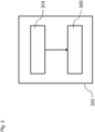
- the parameterizable energy supply device 100 comprises a communication interface 101 and a processor 103.
- the parameterizable energy supply device 100 is designed with: the communication interface 101 for receiving parameterization data via a communication network; and the processor 103, which is designed to set an output characteristic of the parameterizable energy supply device 100 on the basis of the received parameterization data.
- the parameterizable energy supply device 100 can be an electrical energy supply device, such as a voltage supply device or a power supply device, which has at least one adjustable output characteristic. Furthermore, the parameterizable energy supply device 100 can include an electronically adjustable potentiometer for setting an amplitude value of an output voltage or an output current of the parameterizable energy supply device 100 .
- the communication interface 101 can comprise a wired or a wireless communication interface.
- the communication interface 101 includes a serial interface, an interface based on the Standard Power Management Bus (PMBus), an interface based on the Standard Universal Serial Bus (USB), an interface for wireless communication using Radio Frequency Identification (RFID), for example the ISO/IEC 14443 or ISO/IEC 18000-3 standard, an interface for wireless communication using Near Field Communication (NFC), for example according to the ISO/IEC 14443 or ISO/IEC 18092 standard, or an interface for wireless communication one of the standards Bluetooth, ZigBee or Wireless Local Area Network (W-LAN).
- the communication network can be a telephone network, a cellular network, a computer network, for example a local area network (LAN) or a wireless local area network (W-LAN), or the Internet.
- the output characteristic can be a voltage-current output characteristic of the parameterizable energy supply device 100 .
- the parameterization data can characterize or include an output characteristic or an output characteristic parameter of an output characteristic.
- the processor 103 can be designed to set the output characteristic by selecting a pre-stored output characteristic and/or by setting an output characteristic parameter of the output characteristic. Furthermore, the processor 103 can be designed to check the received parameterization data for validity. For example, the parameterization data are checked for validity using a cyclic redundancy check, for example according to the Cyclic Redundancy Check 8 (CRC-8) standard.
- CRC-8 Cyclic Redundancy Check 8
- the parameterizable energy supply device 100 or an electrical energy supply can be parameterized in such a way that any desired output current limitation and/or any desired output voltage limitation can be set.
- the parameterization data or the respective parameters of the limitation for output voltage, output current and/or output power can be adapted as desired.
- the communication interface 101 can be or include a wired or wireless interface, for example an interface for wireless communication using radio, radio frequency identification (RFID) or near field communication (NFC).
- RFID radio frequency identification
- NFC near field communication
- the communication interface 101 can be embodied as a wireless communication interface in order to achieve galvanic isolation between the parameterizable energy supply device 100 and a communication device for parameterizing the parameterizable energy supply device 100 and to avoid compensating currents via the communication interface 101.
- the communication device 200 comprises a user interface 201 and a near-field communication interface 203.
- the communication device 200 for wirelessly setting an output characteristic of a parameterizable energy supply device 100 is designed with: the user interface 201 for specifying parameterization data; and the near-field communication interface 201 for sending the specified parameterization data to the parameterizable energy supply device 100 via a near-field communication network.
- the communication device 200 can be a computer, a smartphone or a handheld device. Furthermore, the communication device 200 can be a mobile communication device.
- User interface 201 may include a keyboard, a display, and/or a touch screen.
- the near-field communication interface 203 can be used to communicate using near-field communication (NFC), for example according to the standard ISO/IEC 14443 or ISO/IEC 18092, be trained. Furthermore, the near-field communication interface 203 of the communication device 200 can be designed to wirelessly supply a near-field communication interface of the parameterizable energy supply device 100 with electrical energy.
- NFC near-field communication
- the near-field communication interface 203 of the communication device 200 can be designed to wirelessly supply a near-field communication interface of the parameterizable energy supply device 100 with electrical energy.
- the communication device 200 can be used to parameterize or set the output characteristic of the parameterizable energy supply device 100 when the parameterizable energy supply device 100 is in a deactivated state.
- FIG. 3 shows a schematic diagram of a method 300 for setting an output characteristic of a parameterizable energy supply device 100 according to an embodiment.
- the method 300 comprises the method steps of transmission 301 and setting 303.
- the method 300 for setting an output characteristic of a parameterizable energy supply device 100 comprises: transmitting 301 parameterization data to the parameterizable energy supply device 100 via a communication network; and setting 303 the output characteristic of the parameterizable energy supply device 100 on the basis of the received parameterization data.
- the setting 303 of the output characteristic can be carried out by selecting a pre-stored output characteristic and/or by setting an output characteristic parameter of the output characteristic. Furthermore, the parameterization data can be transmitted via a near-field communication network.
- Figures 4 to 8 show adjustable output characteristics of a parameterizable energy supply device 100.
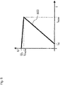
- FIG. 4 shows a schematic diagram of two voltage-current output characteristics 400, 401.
- An output voltage U of a parameterizable energy supply device 100 is plotted on the vertical axis of the coordinate system shown and a corresponding output current I of the parameterizable energy supply device 100 is plotted on the horizontal axis.
- the output voltage U is set to an idling output voltage U 0 and no output current I flows. If the output current I increases, so the output voltage U decreases linearly with a first slope up to a rated load output voltage U NOM . When the output voltage U reaches the nominal load output voltage U NOM , the output current I has increased to a nominal load output current I NOM . This state can correspond to a preferred operating state of the energy supply device 100 that can be parameterized.
- the output voltage U decreases linearly with a second gradient, the second gradient being greater in absolute terms than the first gradient.
- the output current I reaches a short-circuit output current I SC
- the output voltage U reaches a minimum value.
- the minimum value is 0.0001V, 0.001V, 0.01V, 0.1V, 1V or 10V.
- the current limitation of the output current I to the short-circuit output current I SC can correspond to a hard short-circuit in which an output current I flows.
- the no-load output voltage U 0 can correspond to an output voltage U at no-load.
- the nominal load output voltage U NOM can correspond to an output voltage U at a nominal load.
- the rated load output current I NOM may correspond to an output current limit at rated voltage.
- the short-circuit output current I SC can correspond to an output current I in the short-circuit.
- the output voltage U is set to an idling output voltage U 0 and no output current I flows. If the output current I increases, so the output voltage U increases linearly with a third slope up to a nominal load output voltage, which can be greater than the nominal load output voltage U NOM of the voltage-current output characteristic curve 400 . When the output voltage U reaches the rated load output voltage, the output current I has increased to a rated load output current, which can be smaller than the rated load output current I NOM of the voltage-current output characteristic curve 400 .
- This state can correspond to a preferred operating state of the energy supply device 100 that can be parameterized. If the output current I increases further, then the output voltage U decreases linearly with a fourth slope. When a short-circuit output current I SC is reached the output current I, the output voltage U reaches a minimum value. For example, the minimum value is 0.0001V, 0.001V, 0.01V, 0.1V, 1V or 10V.
- the current limitation of the output current I to the short-circuit output current I SC can correspond to a hard short-circuit in which an output current I flows.
- the no-load output voltage U 0 , the nominal load output voltage U NOM , the nominal load output current I NOM , the short-circuit output current I SC and/or the respective gradient can be set in order to set the output characteristic.
- output characteristic parameters of the output characteristic can be expanded as desired. For example, a voltage dip can be adjusted via an output current. Furthermore, a current limitation depending on the output voltage U can be set.
- a fuse mode output characteristic can correspond to the output characteristic curve of one of the voltage-current output characteristics 400, 401.
- the parameterizable energy supply device 100 can switch itself off automatically after a predetermined period of time has elapsed. For example, the parameterizable energy supply device 100 can be manually switched on again or reset by a user.
- the parameterizable energy supply device 100 can be in the form of a current source.
- the voltage-current output characteristics 400, 401 can also be run through as described above. Only voltages and currents have to be interchanged.
- figure 5 shows a schematic diagram of a foldback output characteristic 500.
- An output voltage U of a parameterizable energy supply device 100 is plotted on the vertical axis of the coordinate system shown and a corresponding output current I of the parameterizable energy supply device 100 is plotted on the horizontal axis.
- the output voltage U is set to an idle output voltage U 0 and no output current I flows. If the output current I increases, the output voltage U falls linearly with a first Gradient up to a nominal load output voltage U NOM . When the output voltage U reaches the nominal load output voltage U NOM , the output current I has increased to a nominal load output current I NOM . In the further course, the output voltage U and the output current I decrease linearly with a second gradient, the second gradient being greater in absolute terms than the first gradient. When the output current I reaches a short-circuit output current I SC , the output voltage U reaches a minimum value.
- the minimum value is 0.0001V, 0.001V, 0.01V, 0.1V, 1V or 10V.
- the current limitation of the output current I to the short-circuit output current I SC can correspond to a hard short-circuit in which an output current I flows.
- the nominal load output voltage U NOM can be greater than the no-load output voltage U 0 .
- the output voltage U increases linearly with a further gradient from the no-load output voltage U 0 to the nominal load output voltage U NOM .
- the no-load output voltage U 0 , the nominal load output voltage U NOM , the nominal load output current I NOM , the short-circuit output current I SC and/or the respective gradient can be set in order to set the output characteristic.
- the parameterizable energy supply device 100 can be operated in voltage regulation up to the nominal load output current I NOM or a current limit value.
- the parameterizable energy supply device 100 can be operated in a current limitation up to a hard short circuit.
- the nominal load output current I NOM or the current limit value can be reduced when the output voltage U falls, in order to reduce cable stress in the event of an overload.
- the parameterizable energy supply device 100 can be in the form of a current source. In this case can also be run through the foldback output characteristic 500 as described above. Only voltages and currents have to be interchanged.
- FIG. 6 shows a schematic diagram of a hiccup mode output characteristic 600.
- An output voltage U of a parameterizable energy supply device 100 is plotted on the vertical axis of the coordinate system shown and a corresponding output current I of the parameterizable energy supply device 100 is plotted on the horizontal axis.
- the parameterizable energy supply device 100 is designed as a voltage source, then when the parameterizable energy supply device 100 is idle, the output voltage U is set to an idle output voltage U 0 and no output current I flows. If the output current I increases, the output voltage U falls linearly with a first Gradient up to a nominal load output voltage U NOM . When the output voltage U reaches the nominal load output voltage U NOM , the output current I has increased to a nominal load output current I NOM . In the further course, the output voltage U is lowered, while the output current I is kept constant at the rated load output current I NOM .
- the parameterizable energy supply device 100 is switched off for a first time period t HIOFF and then restarted. If, in the further course, after a second period of time t HION has elapsed, no valid output variable is set, the restart can be aborted and restarted after the first period of time t HIOFF has elapsed . This process can be repeated if necessary.
- the nominal load output voltage U NOM can be greater than the no-load output voltage U 0 .
- the output voltage U increases linearly with a further gradient from the no-load output voltage U 0 to the nominal load output voltage U NOM .
- the no-load output voltage U 0 , the nominal load output voltage U NOM , the output voltage threshold value U HI , the nominal load output current I NOM , the respective slope, the first time period t HIOFF and/or the second time period t HION can be set in order to set the output characteristic.
- the parameterizable energy supply device 100 can be operated in voltage regulation up to the nominal load output current I NOM or a current limit value. In the further course, the parameterizable energy supply device 100 can be operated up to a voltage limit value or current limit value in a voltage regulation or a current regulation.
- the parameterizable energy supply device 100 can be in the form of a current source.
- the hiccup mode output characteristic 600 can also be run through as described above. Only voltages and currents have to be interchanged.
- FIG. 7 shows a schematic diagram of an output characteristic 700 with a dynamic boost.
- An output voltage U of a parameterizable energy supply device 100 is plotted on the vertical axis of the coordinate system shown, and a corresponding output current I of the parameterizable energy supply device 100 is plotted on the horizontal axis.
- the output voltage U is set to an idle output voltage U 0 and no output current I flows. If the output current I increases, the output voltage U decreases linearly with a predetermined value Gradient up to a nominal load output voltage U NOM . When the output voltage U reaches the nominal load output voltage U NOM , the output current I has increased to a nominal load output current I NOM . In the further course, the output current I can be increased to a dynamic output current I DYN for a period of time t DYN , while the output voltage U remains set to the nominal load output voltage U NOM . In the further course, the increase in the output current I can be reversed and the further course of the output characteristic 700 with a dynamic boost can correspond to that of a foldback output characteristic 500, a fuse mode output characteristic or a hiccup mode output characteristic 600.
- the dynamic output current I DYN can be a time-dependent dynamic output current.
- the nominal load output voltage U NOM can be greater than the no-load output voltage U 0 .
- the output voltage U increases at a Increasing the output current I linearly with a further increase from the no-load output voltage U 0 to the rated load output voltage U NOM .
- the no-load output voltage D 0 , the nominal load output voltage U NOM , the nominal load output current I NOM , the short-circuit output current I SC , the dynamic output current I DYN , the predetermined gradient and/or the time period t DYN can be adjusted in order to adjust the output characteristic.
- the parameterizable energy supply device 100 can be operated in voltage regulation up to the dynamic output current I DYN . After the time period t DYN has elapsed, the current increase can be reversed and the output current I can be reduced to the nominal load output current I NOM or a current limit value.
- the further limitation method can correspond to that of a foldback output characteristic 500 , a fuse mode output characteristic or a hiccup mode output characteristic 600 .
- the parameterizable energy supply device 100 can be in the form of a current source.
- the output characteristic curve 700 can also be run through with the dynamic boost as described above. Only voltages and currents have to be interchanged.
- FIG. 8 shows a schematic diagram of a charging characteristic 800 of a storage medium.
- An output voltage U of a parameterizable energy supply device 100 is plotted on the vertical axis of the coordinate system shown, and the time t is plotted on the horizontal axis.
- the charging characteristic 800 may be associated with a constant current and constant voltage charging method, such as an IUU charging method, for a storage medium, such as a lead-acid battery.
- a first charging phase of the charging characteristic 800 the parameterizable energy supply device 100 charges the storage medium with a constant output current I.
- the output voltage U of the parameterizable energy supply device 100 is continuously increased as a function of time.
- T IMDOE When a charging output voltage U 1 is reached by the output voltage U at a first point in time T IMDOE , parameterizable energy supply device 100 changes to a second charging phase with a constant output voltage U. In this case, output voltage U is set to charging output voltage U 1 .
- the output current I drops continuously in the second charging phase.
- the parameterizable energy supply device 100 changes to a third charging phase with a lower constant output voltage U for maintaining the charge of the storage medium.
- the output voltage U is set to an end-of-charge output voltage U 2 .
- the charging output voltage U 1 can be a high output voltage after the end of the first charging phase or a constant current charge. Furthermore, the first charging phase or the constant current charging phase can be time-limited by the first point in time T IMODE .
- the end-of-charge output voltage U 2 can be a float voltage or an end-of-charge voltage for permanent charging of the storage medium.
- the charging output voltage U 1 , the charging end output voltage U 2 , the second point in time t U2MODE and/or the time interval between the points in time TIMODE and t U2MODE can be set in order to set the output characteristic.
- the parameterizable energy supply device 100 can be adapted to different requirements for different applications by selecting an output characteristic and flexible parameterization.
- the parameterizable energy supply device 100 can be adapted to safety requirements or for a reduced cable load by parameterizing output characteristic parameters or limit values.
Description
Die vorliegende Erfindung betrifft die Parametrierung eines Energieversorgungsgerätes.The present invention relates to the parameterization of an energy supply device.
Ein parametrisierbares Energieversorgungsgerät, wie ein universelles Spannungsversorgungsgerät oder ein universelles Stromversorgungsgerät, weist häufig eine vorbestimmte, nicht einstellbare Ausgangskennlinie auf, beispielsweise eine Spannung-Strom-Ausgangskennlinie. Ist das Energieversorgungsgerät beispielsweise als universelles Spannungsversorgungsgerät ausgebildet, kann häufig ein Amplitudenwert einer Ausgangsspannung des parametrisierbaren Energieversorgungsgerätes eingestellt werden, nicht jedoch der Amplitudenwert des korrespondierenden Ausgangsstroms und damit die Spannung-Strom-Ausgangskennlinie des parametrisierbaren Energieversorgungsgerätes.A parameterizable energy supply device, such as a universal voltage supply device or a universal power supply device, often has a predetermined, non-adjustable output characteristic, for example a voltage-current output characteristic. If the energy supply device is designed as a universal voltage supply device, for example, an amplitude value of an output voltage of the parameterizable energy supply device can often be set, but not the amplitude value of the corresponding output current and thus the voltage-current output characteristic of the parameterizable energy supply device.
Die Druckschrift
Die Druckschrift
Die Druckschrift
Die Druckschrift
Die Druckschrift
Es ist die der Erfindung zugrundeliegende Aufgabe, ein effizientes Konzept zum Einstellen einer Ausgangskennlinie eines parametrisierbaren Energieversorgungsgerätes anzugeben.It is the object on which the invention is based to specify an efficient concept for setting an output characteristic of a parameterizable energy supply device.
Diese Aufgabe wird durch Gegenstände mit den Merkmalen nach den unabhängigen Ansprüchen gelöst. Vorteilhafte Ausführungsformen der Erfindung sind Gegenstand der Figuren, der Beschreibung und der abhängigen Ansprüche.This object is solved by objects having the features according to the independent claims. Advantageous embodiments of the invention are the subject matter of the figures, the description and the dependent claims.
Gemäß einem ersten Aspekt der Erfindung wird die Aufgabe durch ein parametrisierbares Energieversorgungsgerät gemäß Anspruch 1 gelöst. Dadurch wird der Vorteil erreicht, dass ein parametrisierbares Energieversorgungsgerät mit einer einstellbaren Ausgangskennlinie bereitgestellt werden kann.According to a first aspect of the invention, the object is achieved by a parameterizable energy supply device according to
Das parametrisierbares Energieversorgungsgerät kann ein elektrisches Energieversorgungsgerät, wie ein Spannungsversorgungsgerät oder ein Stromversorgungsgerät, sein, welches zumindest eine einstellbare Ausgangskennlinie aufweist. Ferner kann das parametrisierbare Energieversorgungsgerät ein elektronisch einstellbares Potentiometer zum Einstellen eines Amplitudenwerts einer Ausgangsspannung oder eines Ausgangsstroms des parametrisierbaren Energieversorgungsgerätes umfassen.The energy supply device that can be parameterized can be an electrical energy supply device, such as a voltage supply device or a power supply device, which has at least one adjustable output characteristic. Furthermore, the parameterizable energy supply device can include an electronically adjustable potentiometer for setting an amplitude value of an output voltage or an output current of the parameterizable energy supply device.
Die Kommunikationsschnittstelle kann eine drahtgebundene und/oder eine drahtlose Kommunikationsschnittstelle umfassen. Beispielsweise umfasst dieThe communication interface can include a wired and/or a wireless communication interface. For example, the
Kommunikationsschnittstelle eine serielle Schnittstelle, eine Schnittstelle nach dem Standard Power Management Bus (PMBus), eine Schnittstelle nach dem Standard Universal Serial Bus (USB), eine Schnittelle zur drahtlosen Kommunikation mittels Radio-Frequency-Identification (RFID), beispielsweise nach dem Standard ISO/IEC 14443 oder ISO/IEC 18000-3, eine Schnittstelle zur drahtlosen Kommunikation mittels Near-Field-Communication (NFC), beispielsweise nach dem Standard ISO/IEC 14443 oder ISO/IEC 18092, oder eine Schnittstelle zur drahtlosen Kommunikation nach einem der Standards Bluetooth, ZigBee oder Wireless Local Area Network (W-LAN). Das Kommunikationsnetzwerk kann ein Telefonnetzwerk, ein Mobilfunknetzwerk, ein Computernetzwerk, beispielsweise ein Local Area Network (LAN) oder ein Wireless Local Area Network (W-LAN), oder das Internet sein.Communication interface a serial interface, an interface based on the Power Management Bus (PMBus) standard, an interface based on the Universal Serial Bus (USB) standard, an interface for wireless communication using Radio Frequency Identification (RFID), for example based on the ISO/ IEC 14443 or ISO/IEC 18000-3, an interface for wireless communication using Near Field Communication (NFC), for example according to the ISO/IEC 14443 or ISO/IEC 18092 standard, or an interface for wireless communication according to one of the Bluetooth standards , ZigBee or Wireless Local Area Network (W-LAN). The communication network can be a telephone network, a cellular network, a computer network, for example a local area network (LAN) or a wireless local area network (W-LAN), or the Internet.
Die Ausgangskennlinie kann eine Spannung-Strom-Ausgangskennlinie des parametrisierbaren Energieversorgungsgerätes sein. Die Parametrisierungsdaten können eine Ausgangskennlinie oder einen Ausgangskennlinienparameter einer Ausgangskennlinie kennzeichnen oder umfassen. Der Prozessor kann ausgebildet sein, die Ausgangskennlinie durch Auswählen einer vorgespeicherten Ausgangskennlinie und/oder durch Einstellen eines Ausgangskennlinienparameters der Ausgangskennlinie einzustellen. Ferner kann der Prozessor ausgebildet sein, die empfangenen Parametrisierungsdaten auf Gültigkeit zu überprüfen. Beispielsweise werden die Parametrisierungsdaten mittels einer zyklischen Redundanzprüfung, beispielsweise nach dem Standard Cyclic Redundancy Check 8 (CRC-8), auf Gültigkeit überprüft.The output characteristic can be a voltage-current output characteristic of the parameterizable energy supply device. The parameterization data can characterize or include an output characteristic or an output characteristic parameter of an output characteristic. The processor can be designed to set the output characteristic by selecting a pre-stored output characteristic and/or by setting an output characteristic parameter of the output characteristic. Furthermore, the processor can be designed to check the received parameterization data for validity. For example, the parameterization data are checked for validity using a cyclic redundancy check, for example according to the Cyclic Redundancy Check 8 (CRC-8) standard.
Erfindungsgemäßist der Prozessor ausgebildet, auf der Basis der empfangenen Parametrisierungsdaten die Ausgangskennlinie aus einer Mehrzahl von vorgespeicherten Ausgangskennlinien auszuwählen, um die Ausgangskennlinie einzustellen.Zusätzlich kann der Prozessor auf der Basis der empfangenen Parametrisierungsdaten einen Ausgangskennlinienparameter der Ausgangskennlinie des parametrisierbaren Energieversorgungsgerätes einstellen, um die Ausgangskennlinie einzustellen. Dadurch wird der Vorteil erreicht, dass die Ausgangskennlinie effizient eingestellt werden kann.According to the invention, the processor is designed to select the output characteristic from a plurality of pre-stored output characteristics on the basis of the received parameterization data in order to set the output characteristic. This achieves the advantage that the output characteristic can be adjusted efficiently.
Die Mehrzahl der vorgespeicherten Ausgangskennlinien kann in einem Speicher des parametrisierbaren Energieversorgungsgerätes vorgespeichert sein.The plurality of pre-stored output characteristics can be pre-stored in a memory of the parameterizable energy supply device.
In einer weiteren vorteilhaften Ausführungsform des parametrisierbaren Energieversorgungsgerätes kennzeichnen die empfangenen Parametrisierungsdaten eine Ausgangskennlinie und/oder einen Ausgangskennlinienparameter einer Ausgangskennlinie, insbesondere einen Ausgangsstrom, eine Ausgangsspannung oder eine Frequenz. Dadurch wird der Vorteil erreicht, dass die Parametrisierungsdaten eine besonders geringe Datenmenge umfassen können.In a further advantageous embodiment of the parameterizable energy supply device, the received parameterization data characterize an output characteristic and/or an output characteristic parameter of an output characteristic, in particular an output current, an output voltage or a frequency. This achieves the advantage that the parameterization data can include a particularly small amount of data.
Erfindungsgemäß ist die Ausgangskennlinie eine der folgenden Ausgangskennlinien: eine Spannung-Strom-Ausgangskennlinie, eine Spannung-Strom-Ausgangskennlinie mit einer Strombegrenzung, eine Foldback-Ausgangskennlinie, eine Hiccup-Mode-Ausgangskennlinie, ein Fuse-Mode-Ausgangskennlinie, eine Ausgangskennlinie mit einem dynamischen Boost, oder eine Ladekennlinie eines Speichermediums. Dadurch wird der Vorteil erreicht, dass eine effiziente Ausgangskennlinie eingestellt werden kann.According to the invention, the output characteristic is one of the following output characteristics: a voltage-current output characteristic, a voltage-current output characteristic with current limitation, a foldback output characteristic, a hiccup-mode output characteristic, a fuse-mode output characteristic, an output characteristic with a dynamic Boost, or a charging characteristic of a storage medium. This achieves the advantage that an efficient output characteristic can be set.
In einer weiteren vorteilhaften Ausführungsform des parametrisierbaren Energieversorgungsgerätes ist der Prozessor ausgebildet, auf der Basis der empfangenen Parametrisierungsdaten einen Ausgangskennlinienparameter der Ausgangskennlinie einzustellen, wobei der Ausgangskennlinienparameter der Ausgangskennlinie zumindest einen der folgenden Parameter umfasst: einen Ausgangsstrom, einen Amplitudenschwellwert des Ausgangsstroms, insbesondere einen maximalen Ausgangsstrom, eine Ausgangsspannung, einen Amplitudenschwellwert der Ausgangsspannung, insbesondere eine maximale Ausgangsspannung, eine Frequenz, einen Frequenzschwellwert der Frequenz, einen Zeitpunkt oder eine Zeitspanne. Dadurch wird der Vorteil erreicht, dass eine Ausgangskennlinie des parametrisierbaren Energieversorgungsgerätes verändert werden kann.In a further advantageous embodiment of the parameterizable energy supply device, the processor is designed to set an output characteristic parameter of the output characteristic on the basis of the received parameterization data, the output characteristic parameter of the output characteristic comprising at least one of the following parameters: an output current, an amplitude threshold value of the output current, in particular a maximum output current, an output voltage, an amplitude threshold value of the output voltage, in particular a maximum output voltage, a frequency, a frequency threshold value of the frequency, a point in time or a period of time. This will make the Achieved advantage that an output characteristic of the parameterizable energy supply device can be changed.
Erfindungsgemäß ist der Prozessor ferner ausgebildet, eine Steigung der Ausgangskennlinie bei Erreichen eines Amplitudenschwellwertes durch eine Ausgangsspannung oder einen Ausgangsstrom des parametrisierbaren Energieversorgungsgerätes zu erhöhen oder zu reduzieren oder eine Steigungsrichtung der Steigung zu ändern. Dadurch wird der Vorteil erreicht, dass eine Charakteristik der Ausgangskennlinie eingestellt werden kann.According to the invention, the processor is also designed to increase or reduce a slope of the output characteristic when an amplitude threshold value is reached by an output voltage or an output current of the parameterizable energy supply device or to change the direction of the slope. This achieves the advantage that a characteristic of the output characteristic can be adjusted.
Die Steigung der Ausgangskennlinie kann positiv, negativ oder Null sein.The slope of the output characteristic can be positive, negative or zero.
In einer weiteren vorteilhaften Ausführungsform des parametrisierbaren Energieversorgungsgerätes ist der Prozessor ferner ausgebildet, zur Einstellung der Ausgangskennlinie einen Amplitudenwert einer Ausgangsspannung oder eines Ausgangsstroms des parametrisierbaren Energieversorgungsgerätes zu einem ersten Zeitpunkt auf einen ersten Amplitudenwert und zu einem zweiten Zeitpunkt auf einen zweiten Amplitudenwert einzustellen. Dadurch wird der Vorteil erreicht, dass eine zeitabhängige Ausgangskennlinie eingestellt werden kann.In a further advantageous embodiment of the parameterizable energy supply device, the processor is also designed to set an amplitude value of an output voltage or an output current of the parameterizable energy supply device at a first point in time to a first amplitude value and at a second point in time to a second amplitude value in order to set the output characteristic. This achieves the advantage that a time-dependent output characteristic can be set.
Der jeweilige Amplitudenwert und/oder der jeweilige Zeitpunkt können in einem Speicher des parametrisierbaren Energieversorgungsgerätes vorgespeichert oder in den Parametrisierungsdaten umfasst sein.The respective amplitude value and/or the respective point in time can be pre-stored in a memory of the parameterizable energy supply device or can be included in the parameterization data.
In einer weiteren vorteilhaften Ausführungsform des parametrisierbaren Energieversorgungsgerätes ist der Prozessor ferner ausgebildet, einen Amplitudenwert einer Ausgangsspannung oder eines Ausgangsstroms des parametrisierbaren Energieversorgungsgerätes gemäß der Ausgangskennlinie nachzuregeln, falls ein Ist-Amplitudenwert der Ausgangsspannung oder des Ausgangsstromes des parametrisierbaren Energieversorgungsgerätes sich von einem jeweils korrespondierenden Sollwert gemäß der Ausgangskennlinie unterscheidet. Dadurch wird der Vorteil erreicht, dass eine effiziente Überwachung und Regelung der Ausgangskennlinie ermöglicht wird.In a further advantageous embodiment of the parameterizable energy supply device, the processor is also designed to readjust an amplitude value of an output voltage or an output current of the parameterizable energy supply device according to the output characteristic if an actual amplitude value of the output voltage or the output current of the parameterizable energy supply device deviates from a respectively corresponding setpoint value according to the Output characteristic differs. This achieves the advantage that efficient monitoring and regulation of the output characteristic is made possible.
Der Ist-Amplitudenwert kann durch eine in dem parametrisierbaren Energieversorgungsgerät integrierte Erfassungseinrichtung erfasst werden. Beispielsweise umfasst das parametrisierbare Energieversorgungsgerät einen Mikrocontroller zum Erfassen des Ist-Amplitudenwertes.The actual amplitude value can be detected by a detection device integrated in the parameterizable energy supply device. For example, the parameterizable energy supply device includes a microcontroller for detecting the actual amplitude value.
In einer weiteren vorteilhaften Ausführungsform des parametrisierbaren Energieversorgungsgerätes ist das parametrisierbare Energieversorgungsgerät mit einem Speicher zum Speichern der empfangenen Parametrisierungsdaten ausgebildet, wobei der Prozessor ausgebildet ist, die Parametrisierungsdaten aus dem Speicher auszulesen und die Ausgangskennlinie des parametrisierbaren Energieversorgungsgerätes auf der Basis der ausgelesenen Parametrisierungsdaten einzustellen. Dadurch wird der Vorteil erreicht, dass die Ausgangskennlinie permanent in dem elektrischen Energieversorgungsgerät gespeichert werden kann.In a further advantageous embodiment of the parameterizable energy supply device, the parameterizable energy supply device is designed with a memory for storing the received parameterization data, the processor being designed to read the parameterization data from the memory and to set the output characteristic of the parameterizable energy supply device on the basis of the parameterization data read out. This achieves the advantage that the output characteristic can be permanently stored in the electrical energy supply device.
Der Speicher kann einen elektrisch löschbaren programmierbaren Nur-Lese-Speicher, beispielsweise einen Electrically-Erasable-Programmable-Read-Only-Memory (EEPROM) Speicher, umfassen. Ferner kann der Prozessor ausgebildet sein, die Parametrisierungsdaten bei einer Aktivierung des parametrisierbaren Energieversorgungsgerätes aus dem Speicher auszulesen.The memory may comprise an electrically erasable programmable read only memory, for example an Electrically Erasable Programmable Read Only Memory (EEPROM) memory. Furthermore, the processor can be designed to read out the parameterization data from the memory when the parameterizable energy supply device is activated.
In einer weiteren vorteilhaften Ausführungsform des parametrisierbaren Energieversorgungsgerätes ist die Kommunikationsschnittstelle ausgebildet, die Parametrisierungsdaten über das Kommunikationsnetzwerk von einem Kommunikationsgerät zu empfangen. Dadurch wird der Vorteil erreicht, dass das parametrisierbare Energieversorgungsgerät effizient parametriert werden kann.In a further advantageous embodiment of the parameterizable energy supply device, the communication interface is designed to receive the parameterization data from a communication device via the communication network. This achieves the advantage that the parameterizable energy supply device can be parameterized efficiently.
Das Kommunikationsgerät kann ein Computer, ein Smartphone oder ein Handgerät sein.The communication device can be a computer, a smartphone or a handheld device.
In einer weiteren vorteilhaften Ausführungsform des parametrisierbaren Energieversorgungsgerätes umfasst die Kommunikationsschnittstelle eine drahtlose Kommunikationsschnittstelle. Dadurch wird der Vorteil erreicht, dass das parametrisierbare Energieversorgungsgerät und das Kommunikationsgerät galvanisch getrennt sein können.In a further advantageous embodiment of the parameterizable energy supply device, the communication interface comprises a wireless communication interface. This achieves the advantage that the parameterizable energy supply device and the communication device can be electrically isolated.
In einer weiteren vorteilhaften Ausführungsform des parametrisierbaren Energieversorgungsgerätes umfasst die Kommunikationsschnittstelle eine Nahfeldkommunikationsschnittstelle. Dadurch wird der Vorteil erreicht, dass eine effiziente drahtlose Kommunikationsschnittstelle verwendet werden kann.In a further advantageous embodiment of the parameterizable energy supply device, the communication interface comprises a near-field communication interface. This achieves the advantage that an efficient wireless communication interface can be used.
Die Nahfeldkommunikationsschnittstelle kann zur Kommunikation mittels Near-Field-Communication (NFC), beispielsweise nach dem Standard ISO/IEC 14443 oder ISO/IEC 18092, ausgebildet sein.The near-field communication interface can be designed for communication using near-field communication (NFC), for example according to the ISO/IEC 14443 or ISO/IEC 18092 standard.
In einer weiteren vorteilhaften Ausführungsform des parametrisierbaren Energieversorgungsgerätes ist die Kommunikationsschnittstelle drahtlos mit elektrischer Energie versorgbar. Dadurch wird der Vorteil erreicht, dass die Ausgangskennlinie in einem deaktivierten Zustand des parametrisierten Energieversorgungsgerätes eingestellt werden kann.In a further advantageous embodiment of the parameterizable energy supply device, the communication interface can be supplied with electrical energy in a wireless manner. This achieves the advantage that the output characteristic can be set in a deactivated state of the parameterized energy supply device.
Die Ausgangskennlinie des parametrisierbaren Energieversorgungsgerätes kann ferner eingestellt werden, wenn das parametrisierbare Energieversorgungsgerät in einer Umverpackung aufgenommen ist.The output characteristic of the parameterizable energy supply device can also be set if the parameterizable energy supply device is included in an outer packaging.
In einer weiteren vorteilhaften Ausführungsform des parametrisierbaren Energieversorgungsgerätes ist die Kommunikationsschnittstelle durch ein Kommunikationsgerät mit elektrischer Energie versorgbar ist. Dadurch wird der Vorteil erreicht, dass das parametrisierbare Energieversorgungsgerät effizient mit elektrischer Energie versorgt werden kann.In a further advantageous embodiment of the parameterizable energy supply device, the communication interface can be supplied with electrical energy by a communication device. This achieves the advantage that the parameterizable energy supply device can be efficiently supplied with electrical energy.
Das Kommunikationsgerät kann das parametrisierbare Energieversorgungsgerät ferner über eine drahtgebundene Kommunikationsverbindung, beispielsweise nach dem Standard Universal Serial Bus (USB), mit elektrischer Energie versorgen.The communication device can also supply the parameterizable energy supply device with electrical energy via a wired communication connection, for example according to the Universal Serial Bus (USB) standard.
In einer weiteren vorteilhaften Ausführungsform des parametrisierbaren Energieversorgungsgerätes umfasst die Kommunikationsschnittstelle eine Antenne, welche innerhalb eines Gehäuses des parametrisierbaren Energieversorgungsgerätes angeordnet oder in einer Gehäusewand eines Gehäuses des parametrisierbaren Energieversorgungsgerätes integriert ist. Dadurch wird der Vorteil erreicht, dass das parametrisierbare Energieversorgungsgerät eine besonders kompakte Bauform aufweisen kann.In a further advantageous embodiment of the parameterizable energy supply device, the communication interface comprises an antenna which is arranged within a housing of the parameterizable energy supply device or is integrated in a housing wall of a housing of the parameterizable energy supply device. This achieves the advantage that the parameterizable energy supply device can have a particularly compact design.
Die Antenne kann durch Leiterbahnen auf einer Platine oder einer Leiterplatte gebildet sein. Ferner kann das Gehäuse des parametrisierbaren Energieversorgungsgerätes ein Kunststoffgehäuse sein oder ein für elektromagnetische Signale durchlässiges Gehäuseelement umfassen.The antenna can be formed by conductor tracks on a printed circuit board or printed circuit board. Furthermore, the housing of the energy supply device that can be parameterized can be a plastic housing or can comprise a housing element that is permeable to electromagnetic signals.
Gemäß einem zweiten Aspekt der Erfindung wird die Aufgabe durch ein Kommunikationsgerät zum drahtlosen Einstellen einer Ausgangskennlinie eines parametrisierbaren Energieversorgungsgerätes gemäß Anspruch 10 gelöst. Dadurch wird der Vorteil erreicht, dass ein Kommunikationsgerät zum effizienten Einstellen einer Ausgangskennlinie eines parametrisierbaren Energieversorgungsgerätes bereitgestellt werden kann.According to a second aspect of the invention, the object is achieved by a communication device for wireless setting of an output characteristic of a parameterizable energy supply device according to claim 10. This achieves the advantage that a communication device can be provided for efficiently setting an output characteristic of a parameterizable energy supply device.
Das Kommunikationsgerät kann ein Computer, ein Smartphone oder ein Handgerät sein. Ferner kann das Kommunikationsgerät ein mobiles Kommunikationsgerät sein. Die Benutzerschnittstelle kann eine Tastatur, eine Anzeigeeinrichtung und/oder einen Touchscreen umfassen.The communication device can be a computer, a smartphone or a handheld device. Furthermore, the communication device can be a mobile communication device. The user interface may include a keyboard, a display, and/or a touch screen.
Die Nahfeldkommunikationsschnittstelle kann zur Kommunikation mittels Near-Field-Communication (NFC), beispielsweise nach dem Standard ISO/IEC 14443 oder ISO/IEC 18092, ausgebildet sein.The near-field communication interface can be designed for communication using near-field communication (NFC), for example according to the ISO/IEC 14443 or ISO/IEC 18092 standard.
In einer vorteilhaften Ausführungsform des Kommunikationsgerätes ist die Nahfeldkommunikationsschnittstelle des Kommunikationsgerätes ferner zum drahtlosen Versorgen einer Nahfeldkommunikationsschnittstelle des parametrisierbaren Energieversorgungsgerätes mit elektrischer Energie ausgebildet. Dadurch wird der Vorteil erreicht, dass die Ausgangskennlinie bei deaktiviertem parametrisierbaren Energieversorgungsgerät eingestellt werden kann.In an advantageous embodiment of the communication device, the near-field communication interface of the communication device is also designed to wirelessly supply electrical energy to a near-field communication interface of the parameterizable energy supply device. This achieves the advantage that the output characteristic can be set when the parameterizable energy supply device is deactivated.
Gemäß einem dritten Aspekt der Erfindung wird die Aufgabe durch ein Verfahren zum Einstellen einer Ausgangskennlinie eines parametrisierbaren Energieversorgungsgerätes gemäß Anspruch 12 gelöst. Dadurch wird der Vorteil erreicht, dass die Ausgangskennlinie des parametrisierbaren Energieversorgungsgerätes auf effiziente Weise eingestellt werden kann.According to a third aspect of the invention, the object is achieved by a method for setting an output characteristic of a parameterizable energy supply device according to claim 12. This achieves the advantage that the output characteristic of the parameterizable energy supply device can be set in an efficient manner.
Das Einstellen der Ausgangskennlinie wird erfindungsgemäß durch Auswählen einer vorgespeicherten Ausgangskennlinie durchgeführt und kann zusätzlich durch Einstellen eines Ausgangskennlinienparameters der Ausgangskennlinie durchgeführt werden.According to the invention, the output characteristic is set by selecting a pre-stored output characteristic and can additionally be set by setting an output characteristic parameter of the output characteristic.
In einer vorteilhaften Ausführungsform des Verfahrens werden die Parametrisierungsdaten über ein Nahfeldkommunikationsnetzwerk übertragen. Dadurch wird der Vorteil erreicht, dass ein effizientes Kommunikationsnetzwerk verwendet werden kann.In an advantageous embodiment of the method, the parameterization data are transmitted via a near-field communication network. This achieves the advantage that an efficient communication network can be used.
Ausführungsbeispiele der Erfindung sind in den Zeichnungen dargestellt und werden im Folgenden näher beschrieben.Exemplary embodiments of the invention are shown in the drawings and are described in more detail below.
Es zeigen:
- Fig. 1
- ein schematisches Diagramm eines parametrisierbaren Energieversorgungsgerätes gemäß einer Ausführungsform;
- Fig. 2
- ein schematisches Diagramm eines Kommunikationsgerätes zum drahtlosen Einstellen einer Ausgangskennlinie eines parametrisierbaren Energieversorgungsgerätes gemäß einer Ausführungsform;
- Fig. 3
- ein schematisches Diagramm eines Verfahrens zum Einstellen einer Ausgangskennlinie eines parametrisierbaren Energieversorgungsgerätes gemäß einer Ausführungsform;
- Fig. 4
- ein schematisches Diagramm zweier Spannung-Strom-Ausgangskennlinien;
- Fig. 5
- ein schematisches Diagramm einer Foldback-Ausgangskennlinie;
- Fig. 6
- ein schematisches Diagramm einer Hiccup-Mode-Ausgangskennlinie;
- Fig. 7
- ein schematisches Diagramm einer Ausgangskennlinie mit einem dynamischen Boost; und
- Fig. 8
- ein schematisches Diagramm einer Ladekennlinie eines Speichermediums.
- 1
- a schematic diagram of a parameterizable power supply device according to an embodiment;
- 2
- a schematic diagram of a communication device for wireless setting of an output characteristic of a parameterizable energy supply device according to an embodiment;
- 3
- a schematic diagram of a method for setting an output characteristic of a parameterizable energy supply device according to one embodiment;
- 4
- a schematic diagram of two voltage-current output characteristics;
- figure 5
- a schematic diagram of a foldback output characteristic;
- 6
- a schematic diagram of a hiccup mode output characteristic;
- 7
- a schematic diagram of an output characteristic with a dynamic boost; and
- 8
- a schematic diagram of a loading characteristic of a storage medium.
Das parametrisierbares Energieversorgungsgerät 100 ist ausgebildet mit: der Kommunikationsschnittstelle 101 zum Empfangen von Parametrisierungsdaten über ein Kommunikationsnetzwerk; und dem Prozessor 103, welcher ausgebildet ist, eine Ausgangskennlinie des parametrisierbaren Energieversorgungsgerätes 100 auf der Basis der empfangenen Parametrisierungsdaten einzustellen.The parameterizable
Das parametrisierbares Energieversorgungsgerät 100 kann ein elektrisches Energieversorgungsgerät, wie ein Spannungsversorgungsgerät oder ein Stromversorgungsgerät, sein, welches zumindest eine einstellbare Ausgangskennlinie aufweist. Ferner kann das parametrisierbare Energieversorgungsgerät 100 ein elektronisch einstellbares Potentiometer zum Einstellen eines Amplitudenwerts einer Ausgangsspannung oder eines Ausgangsstroms des parametrisierbaren Energieversorgungsgerätes 100 umfassen.The parameterizable
Die Kommunikationsschnittstelle 101 kann eine drahtgebundene oder eine drahtlose Kommunikationsschnittstelle umfassen. Beispielsweise umfasst die Kommunikationsschnittstelle 101 eine serielle Schnittstelle, eine Schnittstelle nach dem Standard Power Management Bus (PMBus), eine Schnittstelle nach dem Standard Universal Serial Bus (USB), eine Schnittelle zur drahtlosen Kommunikation mittels Radio-Frequency-Identification (RFID), beispielsweise nach dem Standard ISO/IEC 14443 oder ISO/IEC 18000-3, eine Schnittstelle zur drahtlosen Kommunikation mittels Near-Field-Communication (NFC), beispielsweise nach dem Standard ISO/IEC 14443 oder ISO/IEC 18092, oder eine Schnittstelle zur drahtlosen Kommunikation nach einem der Standards Bluetooth, ZigBee oder Wireless Local Area Network (W-LAN). Das Kommunikationsnetzwerk kann ein Telefonnetzwerk, ein Mobilfunknetzwerk, ein Computernetzwerk, beispielsweise ein Local Area Network (LAN) oder ein Wireless Local Area Network (W-LAN), oder das Internet sein.The
Die Ausgangskennlinie kann eine Spannung-Strom-Ausgangskennlinie des parametrisierbaren Energieversorgungsgerätes 100 sein. Die Parametrisierungsdaten können eine Ausgangskennlinie oder einen Ausgangskennlinienparameter einer Ausgangskennlinie kennzeichnen oder umfassen. Der Prozessor 103 kann ausgebildet sein, die Ausgangskennlinie durch Auswählen einer vorgespeicherten Ausgangskennlinie und/oder durch Einstellen eines Ausgangskennlinienparameters der Ausgangskennlinie einzustellen. Ferner kann der Prozessor 103 ausgebildet sein, die empfangenen Parametrisierungsdaten auf Gültigkeit zu überprüfen. Beispielsweise werden die Parametrisierungsdaten mittels einer zyklischen Redundanzprüfung, beispielsweise nach dem Standard Cyclic Redundancy Check 8 (CRC-8), auf Gültigkeit überprüft.The output characteristic can be a voltage-current output characteristic of the parameterizable
Gemäß einer Ausführungsform kann das parametrisierbare Energieversorgungsgerät 100 oder eine elektrische Energieversorgung derart parametriert werden, dass eine beliebige Ausgangsstrombegrenzung und/oder eine beliebige Ausgangsspannungsbegrenzung eingestellt werden kann.According to one embodiment, the parameterizable
Gemäß einer weiteren Ausführungsform können die Parametrisierungsdaten oder die jeweiligen Parameter der Begrenzung für Ausgangsspannung, Ausgangsstrom und/oder Ausgangsleistung beliebig angepasst werden.According to a further embodiment, the parameterization data or the respective parameters of the limitation for output voltage, output current and/or output power can be adapted as desired.
Gemäß einer weiteren Ausführungsform kann die Kommunikationsschnittstelle 101 eine drahtgebundene oder eine drahtlose Schnittstelle, beispielsweise eine Schnittelle zur drahtlosen Kommunikation mittels Funk, Radio-Frequency-Identification (RFID) oder Near-Field-Communication (NFC) sein oder umfassen.According to a further embodiment, the
Gemäß einer weiteren Ausführungsform kann die Kommunikationsschnittstelle 101 als drahtlose Kommunikationsschnittstelle ausgebildet sein, um eine galvanische Trennung zwischen dem parametrisierbaren Energieversorgungsgerät 100 und einem Kommunikationsgerät zum Parametrieren des parametrisierbaren Energieversorgungsgerätes 100 zu erreichen und um Ausgleichsströme über die Kommunikationsschnittstelle 101 zu vermeiden.According to a further embodiment, the
Das Kommunikationsgerät 200 zum drahtlosen Einstellen einer Ausgangskennlinie eines parametrisierbaren Energieversorgungsgerätes 100 ist ausgebildet mit: der Benutzerschnittstelle 201 zum Festlegen von Parametrisierungsdaten; und der Nahfeldkommunikationsschnittstelle 201 zum Aussenden der festgelegten Parametrisierungsdaten an das parametrisierbare Energieversorgungsgerät 100 über ein Nahfeldkommunikationsnetzwerk.The
Das Kommunikationsgerät 200 kann ein Computer, ein Smartphone oder ein Handgerät sein. Ferner kann das Kommunikationsgerät 200 ein mobiles Kommunikationsgerät sein. Die Benutzerschnittstelle 201 kann eine Tastatur, eine Anzeigeeinrichtung und/oder einen Touchscreen umfassen.The
Die Nahfeldkommunikationsschnittstelle 203 kann zur Kommunikation mittels Near-Field-Communication (NFC), beispielsweise nach dem Standard ISO/IEC 14443 oder ISO/IEC 18092, ausgebildet sein. Ferner kann die Nahfeldkommunikationsschnittstelle 203 des Kommunikationsgerätes 200 zum drahtlosen Versorgen einer Nahfeldkommunikationsschnittstelle des parametrisierbaren Energieversorgungsgerätes 100 mit elektrischer Energie ausgebildet sein.The near-
Gemäß einer Ausführungsform kann mittels des Kommunikationsgerätes 200 eine Parametrierung oder ein Einstellen der Ausgangskennlinie des parametrisierbaren Energieversorgungsgerätes 100 in einem deaktivierten Zustand des parametrisierbaren Energieversorgungsgerätes 100 durchgeführt werden.According to one specific embodiment, the
Das Verfahren 300 zum Einstellen einer Ausgangskennlinie eines parametrisierbaren Energieversorgungsgerätes 100 umfasst: Übertragen 301 von Parametrisierungsdaten an das parametrisierbare Energieversorgungsgerät 100 über ein Kommunikationsnetzwerk; und Einstellen 303 der Ausgangskennlinie des parametrisierbaren Energieversorgungsgerätes 100 auf der Basis der empfangenen Parametrisierungsdaten.The
Das Einstellen 303 der Ausgangskennlinie kann durch Auswählen einer vorgespeicherten Ausgangskennlinie und/oder durch Einstellen eines Ausgangskennlinienparameters der Ausgangskennlinie durchgeführt werden. Ferner können die Parametrisierungsdaten über ein Nahfeldkommunikationsnetzwerk übertragen werden.The setting 303 of the output characteristic can be carried out by selecting a pre-stored output characteristic and/or by setting an output characteristic parameter of the output characteristic. Furthermore, the parameterization data can be transmitted via a near-field communication network.
Ist das parametrisierbare Energieversorgungsgerät 100 als eine Spannungsquelle ausgebildet, so ist bei der Spannung-Strom-Ausgangskennlinie 400 in einem Leerlauf des parametrisierbaren Energieversorgungsgerätes 100 die Ausgangsspannung U auf eine Leerlaufausgangsspannung U0 eingestellt und es fließt kein Ausgangsstrom I. Erhöht sich der Ausgangsstrom I, so sinkt die Ausgangsspannung U linear mit einer ersten Steigung bis zu einer Nennlastausgangsspannung UNOM. Bei Erreichen der Nennlastausgangsspannung UNOM durch die Ausgangsspannung U ist der Ausgangsstrom I auf einen Nennlastausgangsstrom INOM angestiegen. Dieser Zustand kann einem bevorzugten Betriebszustand des parametrisierbaren Energieversorgungsgerätes 100 entsprechen. Erhöht sich der Ausgangsstrom I weiter, so sinkt die Ausgangsspannung U linear mit einer zweiten Steigung, wobei die zweite Steigung betragsmäßig größer ist als die erste Steigung. Bei Erreichen eines Kurzschlussausgangsstroms lSC durch den Ausgangsstrom I erreicht die Ausgangsspannung U einen Minimalwert. Beispielsweise beträgt der Minimalwert 0,0001V, 0,001V, 0,01V, 0,1V, 1V oder 10V. Die Strombegrenzung des Ausgangsstroms I auf den Kurzschlussausgangsstrom ISC kann einem harten Kurzschluss entsprechen, bei welchem ein Ausgangsstrom I fließt.If the parameterizable
Die Leerlaufausgangsspannung U0 kann einer Ausgangsspannung U im Leerlauf entsprechen. Ferner kann die Nennlastausgangsspannung UNOM einer Ausgangsspannung U bei einer Nennlast entsprechen. Der Nennlastausgangsstrom INOM kann einem Ausgangsstromgrenzwert bei Nennspannung entsprechen. Ferner kann der Kurzschlussausgangsstrom ISC einem Ausgangsstrom I im Kurzschluss entsprechen.The no-load output voltage U 0 can correspond to an output voltage U at no-load. Furthermore, the nominal load output voltage U NOM can correspond to an output voltage U at a nominal load. The rated load output current I NOM may correspond to an output current limit at rated voltage. Furthermore, the short-circuit output current I SC can correspond to an output current I in the short-circuit.
Ist das parametrisierbare Energieversorgungsgerät 100 als eine Spannungsquelle ausgebildet, so ist bei der Spannung-Strom-Ausgangskennlinie 401 in einem Leerlauf des parametrisierbaren Energieversorgungsgerätes 100 die Ausgangsspannung U auf eine Leerlaufausgangsspannung U0 eingestellt und es fließt kein Ausgangsstrom I. Erhöht sich der Ausgangsstrom I, so steigt die Ausgangsspannung U linear mit einer dritten Steigung bis zu einer Nennlastausgangsspannung, welche größer als die Nennlastausgangsspannung UNOM der Spannung-Strom-Ausgangskennlinie 400 sein kann. Bei Erreichen der Nennlastausgangsspannung durch die Ausgangsspannung U ist der Ausgangsstrom I auf einen Nennlastausgangsstrom angestiegen, welcher kleiner als der Nennlastausgangsstrom INOM der Spannung-Strom-Ausgangskennlinie 400 sein kann. Dieser Zustand kann einem bevorzugten Betriebszustand des parametrisierbaren Energieversorgungsgerätes 100 entsprechen. Erhöht sich der Ausgangsstrom I weiter, so sinkt die Ausgangsspannung U linear mit einer vierten Steigung. Bei Erreichen eines Kurzschlussausgangsstroms ISC durch den Ausgangsstrom I erreicht die Ausgangsspannung U einen Minimalwert. Beispielsweise beträgt der Minimalwert 0,0001V, 0,001V, 0,01V, 0,1V, 1V oder 10V. Die Strombegrenzung des Ausgangsstroms I auf den Kurzschlussausgangsstrom ISC kann einem harten Kurzschluss entsprechen, bei welchem ein Ausgangsstrom I fließt.If the parameterizable
Gemäß einer Ausführungsform können die Leerlaufausgangsspannung U0, die Nennlastausgangsspannung UNOM, der Nennlastausgangsstrom INOM, der Kurzschlussausgangsstrom ISC und/oder die jeweilige Steigung eingestellt werden, um die Ausgangskennlinie einzustellen.According to one embodiment, the no-load output voltage U 0 , the nominal load output voltage U NOM , the nominal load output current I NOM , the short-circuit output current I SC and/or the respective gradient can be set in order to set the output characteristic.
Gemäß einer weiteren Ausführungsform können Ausgangskennlinienparameter der Ausgangskennlinie beliebig erweitert werden. Beispielsweise kann ein Spannungseinbruch über einen Ausgangsstrom einstellbar ausgeführt werden. Ferner kann eine Strombegrenzung in Abhängigkeit von der Ausgangsspannung U eingestellt werden.According to a further embodiment, output characteristic parameters of the output characteristic can be expanded as desired. For example, a voltage dip can be adjusted via an output current. Furthermore, a current limitation depending on the output voltage U can be set.
Gemäß einer weiteren Ausführungsform kann eine Fuse-Mode-Ausgangskennlinie dem Ausgangskennlinienverlauf einer der Spannung-Strom-Ausgangskennlinien 400, 401 entsprechen. Wird jedoch ein vorbestimmter Stromgrenzwert durch den Ausgangsstrom I überschritten oder ein vorbestimmter Spannungsgrenzwert durch die Ausgangsspannung U unterschritten, kann sich das parametrisierbare Energieversorgungsgerät 100 nach Ablauf einer vorbestimmten Zeitspanne selbstständig abschalten. Beispielsweise kann das parametrisierbare Energieversorgungsgerät 100 durch einen Benutzer manuell wieder eingeschaltet oder zurückgesetzt werden.According to a further embodiment, a fuse mode output characteristic can correspond to the output characteristic curve of one of the voltage-
Gemäß einer weiteren Ausführungsform kann das parametrisierbare Energieversorgungsgerät 100 als Stromquelle ausgebildet sein. In diesem Fall können ebenfalls die Spannung-Strom-Ausgangskennlinien 400, 401 wie oben beschrieben durchlaufen werden. Es sind lediglich Spannungen und Ströme gegeneinander zu vertauschen.According to a further specific embodiment, the parameterizable
Ist das parametrisierbare Energieversorgungsgerät 100 als eine Spannungsquelle ausgebildet, so ist in einem Leerlauf des parametrisierbaren Energieversorgungsgerätes 100 die Ausgangsspannung U auf eine Leerlaufausgangsspannung U0 eingestellt und es fließt kein Ausgangsstrom I. Erhöht sich der Ausgangsstrom I, so sinkt die Ausgangsspannung U linear mit einer ersten Steigung bis zu einer Nennlastausgangsspannung UNOM. Bei Erreichen der Nennlastausgangsspannung UNOM durch die Ausgangsspannung U ist der Ausgangsstrom I auf einen Nennlastausgangsstrom INOM angestiegen. Im weiteren Verlauf sinken die Ausgangsspannung U und der Ausgangsstrom I linear mit einer zweiten Steigung, wobei die zweite Steigung betragsmäßig größer ist als die erste Steigung. Bei Erreichen eines Kurzschlussausgangsstroms ISC durch den Ausgangsstrom I erreicht die Ausgangsspannung U einen Minimalwert. Beispielsweise beträgt der Minimalwert 0,0001V, 0,001V, 0,01V, 0,1V, 1V oder 10V. Die Strombegrenzung des Ausgangsstroms I auf den Kurzschlussausgangsstrom ISC kann einem harten Kurzschluss entsprechen, bei welchem ein Ausgangsstrom I fließt.If the parameterizable
Gemäß einer Ausführungsform kann die Nennlastausgangsspannung UNOM größer sein als die Leerlaufausgangsspannung U0. In diesem Fall steigt die Ausgangsspannung U bei einer Erhöhung des Ausgangsstroms I linear mit einer weiteren Steigung von der Leerlaufausgangsspannung U0 bis zu der Nennlastausgangsspannung UNOM an.According to one embodiment, the nominal load output voltage U NOM can be greater than the no-load output voltage U 0 . In this case, when the output current I increases, the output voltage U increases linearly with a further gradient from the no-load output voltage U 0 to the nominal load output voltage U NOM .
Gemäß einer Ausführungsform können die Leerlaufausgangsspannung U0, die Nennlastausgangsspannung UNOM, der Nennlastausgangsstrom INOM, der Kurzschlussausgangsstrom ISC und/oder die jeweilige Steigung eingestellt werden, um die Ausgangskennlinie einzustellen.According to one embodiment, the no-load output voltage U 0 , the nominal load output voltage U NOM , the nominal load output current I NOM , the short-circuit output current I SC and/or the respective gradient can be set in order to set the output characteristic.
Gemäß einer weiteren Ausführungsform kann das parametrisierbare Energieversorgungsgerät 100 bis zu dem Nennlastausgangsstrom INOM oder einem Stromgrenzwert in einer Spannungsregelung betrieben werden. Im weiteren Verlauf kann das parametrisierbare Energieversorgungsgerät 100 bis zu einem harten Kurzschluss in einer Strombegrenzung betrieben werden. Der Nennlastausgangsstrom INOM oder der Stromgrenzwert kann bei sinkender Ausgangsspannung U reduziert werden, um in einem Überlastfall eine Kabelbelastung zu reduzieren.According to a further specific embodiment, the parameterizable
Gemäß einer weiteren Ausführungsform kann das parametrisierbare Energieversorgungsgerät 100 als Stromquelle ausgebildet sein. In diesem Fall kann ebenfalls die Foldback-Ausgangskennlinie 500 wie oben beschrieben durchlaufen werden. Es sind lediglich Spannungen und Ströme gegeneinander zu vertauschen.According to a further specific embodiment, the parameterizable
Ist das parametrisierbare Energieversorgungsgerät 100 als eine Spannungsquelle ausgebildet, so ist in einem Leerlauf des parametrisierbaren Energieversorgungsgerätes 100 die Ausgangsspannung U auf eine Leerlaufausgangsspannung U0 eingestellt und es fließt kein Ausgangsstrom I. Erhöht sich der Ausgangsstrom I, so sinkt die Ausgangsspannung U linear mit einer ersten Steigung bis zu einer Nennlastausgangsspannung UNOM. Bei Erreichen der Nennlastausgangsspannung UNOM durch die Ausgangsspannung U ist der Ausgangsstrom I auf einen Nennlastausgangsstrom INOM angestiegen. Im weiteren Verlauf wird die Ausgangsspannung U abgesenkt, während der Ausgangsstrom I konstant auf dem Nennlastausgangsstrom INOM gehalten wird. Sinkt die Ausgangsspannung U unter einen Ausgangsspannungsschwellwert UHI, so wird das parametrisierbare Energieversorgungsgerät 100 für eine erste Zeitspanne tHIOFF abgeschaltet und im Anschluss daran neu gestartet. Stellt sich im weiteren Verlauf nach Ablauf einer zweiten Zeitspanne tHION keine gültige Ausgangsgröße ein, so kann der Neustart abgebrochen werden und nach Ablauf der ersten Zeitspanne tHIOFF erneut gestartet werden. Dieser Vorgang kann gegebenenfalls wiederholt werden.If the parameterizable
Gemäß einer Ausführungsform kann die Nennlastausgangsspannung UNOM größer sein als die Leerlaufausgangsspannung U0. In diesem Fall steigt die Ausgangsspannung U bei einer Erhöhung des Ausgangsstroms I linear mit einer weiteren Steigung von der Leerlaufausgangsspannung U0 bis zu der Nennlastausgangsspannung UNOM an.According to one embodiment, the nominal load output voltage U NOM can be greater than the no-load output voltage U 0 . In this case, when the output current I increases, the output voltage U increases linearly with a further gradient from the no-load output voltage U 0 to the nominal load output voltage U NOM .
Gemäß einer Ausführungsform können die Leerlaufausgangsspannung U0, die Nennlastausgangsspannung UNOM, der Ausgangsspannungsschwellwert UHI, der Nennlastausgangsstrom INOM, die jeweilige Steigung, die erste Zeitspanne tHIOFF und/oder die zweite Zeitspanne tHION eingestellt werden, um die Ausgangskennlinie einzustellen.According to one embodiment, the no-load output voltage U 0 , the nominal load output voltage U NOM , the output voltage threshold value U HI , the nominal load output current I NOM , the respective slope, the first time period t HIOFF and/or the second time period t HION can be set in order to set the output characteristic.
Gemäß einer weiteren Ausführungsform kann das parametrisierbare Energieversorgungsgerät 100 bis zu dem Nennlastausgangsstrom INOM oder einem Stromgrenzwert in einer Spannungsregelung betrieben werden. Im weiteren Verlauf kann das parametrisierbare Energieversorgungsgerät 100 bis zu einem Spannungsgrenzwert oder Stromgrenzwert in einer Spannungsregelung oder einer Stromregelung betrieben werden.According to a further specific embodiment, the parameterizable
Gemäß einer weiteren Ausführungsform kann das parametrisierbare Energieversorgungsgerät 100 als Stromquelle ausgebildet sein. In diesem Fall kann ebenfalls die Hiccup-Mode-Ausgangskennlinie 600 wie oben beschrieben durchlaufen werden. Es sind lediglich Spannungen und Ströme gegeneinander zu vertauschen.According to a further specific embodiment, the parameterizable
Ist das parametrisierbare Energieversorgungsgerät 100 als eine Spannungsquelle ausgebildet, so ist in einem Leerlauf des parametrisierbaren Energieversorgungsgerätes 100 die Ausgangsspannung U auf eine Leerlaufausgangsspannung U0 eingestellt und es fließt kein Ausgangsstrom I. Erhöht sich der Ausgangsstrom I, so sinkt die Ausgangsspannung U linear mit einer vorbestimmten Steigung bis zu einer Nennlastausgangsspannung UNOM. Bei Erreichen der Nennlastausgangsspannung UNOM durch die Ausgangsspannung U ist der Ausgangsstrom I auf einen Nennlastausgangsstrom INOM angestiegen. Im weiteren Verlauf kann der Ausgangsstrom I für eine Zeitspanne tDYN auf einen dynamischen Ausgangsstrom IDYN erhöht werden, während die Ausgangsspannung U auf die Nennlastausgangsspannung UNOM eingestellt bleibt. Im weiteren Verlauf kann die Erhöhung des Ausgangstroms I zurückgenommen werden und der weitere Verlauf der Ausgangskennlinie 700 mit einem dynamischen Boost kann dem einer Foldback-Ausgangskennlinie 500, einer Fuse-Mode-Ausgangskennlinie oder einer Hiccup-Mode-Ausgangskennlinie 600 entsprechen.If the parameterizable
Der dynamische Ausgangsstrom IDYN kann ein zeitabhängiger dynamischer Ausgangsstrom sein.The dynamic output current I DYN can be a time-dependent dynamic output current.
Gemäß einer Ausführungsform kann die Nennlastausgangsspannung UNOM größer sein als die Leerlaufausgangsspannung U0. In diesem Fall steigt die Ausgangsspannung U bei einer Erhöhung des Ausgangsstroms I linear mit einer weiteren Steigung von der Leerlaufausgangsspannung U0 bis zu der Nennlastausgangsspannung UNOM an.According to one embodiment, the nominal load output voltage U NOM can be greater than the no-load output voltage U 0 . In this case, the output voltage U increases at a Increasing the output current I linearly with a further increase from the no-load output voltage U 0 to the rated load output voltage U NOM .
Gemäß einer Ausführungsform können die Leerlaufausgangsspannung D0, die Nennlastausgangsspannung UNOM, der Nennlastausgangsstrom INOM, der Kurzschlussausgangsstrom ISC, der dynamische Ausgangsstrom IDYN, die vorbestimmte Steigung und/oder die Zeitspanne tDYN eingestellt werden, um die Ausgangskennlinie einzustellen.According to one embodiment, the no-load output voltage D 0 , the nominal load output voltage U NOM , the nominal load output current I NOM , the short-circuit output current I SC , the dynamic output current I DYN , the predetermined gradient and/or the time period t DYN can be adjusted in order to adjust the output characteristic.
Gemäß einer weiteren Ausführungsform kann das parametrisierbare Energieversorgungsgerät 100 bis zu dem dynamischen Ausgangsstrom IDYN in einer Spannungsregelung betrieben werden. Nach Ablauf der Zeitspanne tDYN kann die Stromerhöhung zurückgenommen werden und der Ausgangsstrom I auf den Nennlastausgangsstrom INOM oder einen Stromgrenzwert zurückgenommen werden. Im weiteren Verlauf kann das weitere Begrenzungsverfahren dem einer Foldback-Ausgangskennlinie 500, einer Fuse-Mode-Ausgangskennlinie oder einer Hiccup-Mode-Ausgangskennlinie 600 entsprechen.According to a further specific embodiment, the parameterizable
Gemäß einer weiteren Ausführungsform kann das parametrisierbare Energieversorgungsgerät 100 als Stromquelle ausgebildet sein. In diesem Fall kann ebenfalls die Ausgangskennlinie 700 mit dem dynamischen Boost wie oben beschrieben durchlaufen werden. Es sind lediglich Spannungen und Ströme gegeneinander zu vertauschen.According to a further specific embodiment, the parameterizable
Die Ladekennlinie 800 kann einem Konstantstrom- und Konstantspannungs-Ladeverfahren, wie einem IUU-Ladeverfahren, für ein Speichermedium, wie eine Bleibatterie, zugeordnet sein. In einer ersten Ladephase der Ladekennlinie 800 lädt das parametrisierbare Energieversorgungsgerät 100 das Speichermedium mit einem konstanten Ausgangsstrom I. Um den Ausgangsstrom I konstant zu halten wird die Ausgangsspannung U des parametrisierbaren Energieversorgungsgerätes 100 als Funktion der Zeit kontinuierlich erhöht. Bei Erreichen eines einer Ladeausgangsspannung U1 durch die Ausgangsspannung U zu einem ersten Zeitpunkt TIMDOE wechselt das parametrisierbare Energieversorgungsgerät 100 in eine zweite Ladephase mit einer konstanten Ausgangsspannung U. Hierbei wird die Ausgangsspannung U auf die Ladeausgangsspannung U1 eingestellt. Der Ausgangsstrom I fällt in der zweiten Ladephase kontinuierlich ab. Bei Erreichen des zweiten Zeitpunkts tU2MODE wechselt das parametrisierbare Energieversorgungsgerät 100 in eine dritte Ladephase mit einer geringeren konstanten Ausgangsspannung U zum Erhalten der Ladung des Speichermediums. Hierbei wird die Ausgangsspannung U auf eine Ladeschlussausgangsspannung U2 eingestellt.The charging characteristic 800 may be associated with a constant current and constant voltage charging method, such as an IUU charging method, for a storage medium, such as a lead-acid battery. In a first charging phase of the charging characteristic 800, the parameterizable
Die Ladeausgangsspannung U1 kann eine hohe Ausgangsspannung nach Ende der ersten Ladephase oder einer Konstantstromladung sein. Ferner kann die erste Ladephase oder die Konstantstromladephase durch den ersten Zeitpunkt TIMODE zeitlich begrenzt sein. Die Ladeschlussausgangsspannung U2 kann eine Erhaltungsspannung oder eine Ladeschlussspannung zum dauerhaften Laden des Speichermediums sein.The charging output voltage U 1 can be a high output voltage after the end of the first charging phase or a constant current charge. Furthermore, the first charging phase or the constant current charging phase can be time-limited by the first point in time T IMODE . The end-of-charge output voltage U 2 can be a float voltage or an end-of-charge voltage for permanent charging of the storage medium.
Gemäß einer Ausführungsform können die Ladeausgangsspannung U1, die Ladeschlussausgangsspannung U2, der zweite Zeitpunkt tU2MODE und/oder die Zeitspanne zwischen den Zeitpunkten TIMODE und tU2MODE eingestellt werden, um die Ausgangskennlinie einzustellen.According to one embodiment, the charging output voltage U 1 , the charging end output voltage U 2 , the second point in time t U2MODE and/or the time interval between the points in time TIMODE and t U2MODE can be set in order to set the output characteristic.
Gemäß einer Ausführungsform können die in den
Gemäß einer weiteren Ausführungsform kann das parametrisierbare Energieversorgungsgerät 100 durch eine Auswahl einer Ausgangskennlinie und eine flexible Parametrierung auf unterschiedliche Anforderungen für verschiedene Einsatzzwecke angepasst werden.According to a further specific embodiment, the parameterizable
Gemäß einer weiteren Ausführungsform kann das parametrisierbare Energieversorgungsgerät 100 durch eine Parametrierung von Ausgangskennlinienparametern oder Grenzwerten an Sicherheitsanforderungen oder für eine verringerte Kabelbelastung angepasst werden.According to a further embodiment, the parameterizable
Alle in Verbindung mit einzelnen Ausführungsformen der Erfindung erläuterten und gezeigten Merkmale können in unterschiedlicher Kombination in dem erfindungsgemäßen Gegenstand vorgesehen sein, um gleichzeitig deren vorteilhafte Wirkungen zu realisieren.All of the features explained and shown in connection with individual embodiments of the invention can be provided in different combinations in the object according to the invention in order to realize their advantageous effects at the same time.
Der Schutzbereich der vorliegenden Erfindung ist durch die Ansprüche gegeben und wird durch die in der Beschreibung erläuterten oder den Figuren gezeigten Merkmale nicht beschränkt.The scope of protection of the present invention is given by the claims and is not limited by the features explained in the description or shown in the figures.
- 100100
- Parametrisierbares EnergieversorgungsgerätParameterizable energy supply device
- 101101
- Kommunikationsschnittstellecommunication interface
- 103103
- Prozessorprocessor
- 200200
- Kommunikationsgerätcommunication device
- 201201
- Benutzerschnittstelleuser interface
- 203203
- Nahfeldkommunikationsschnittstellenear field communication interface
- 300300
- Verfahrenprocedure
- 301301
- ÜbertragenTransfer
- 303303
- EinstellenSet to
- 400400
- Spannung-Strom-AusgangskennlinieVoltage-current output characteristic
- 401401
- Spannung-Strom-AusgangskennlinieVoltage-current output characteristic
- 500500
- Foldback-AusgangskennlinieFoldback output characteristic
- 600600
- Hiccup-Mode-AusgangskennlinieHiccup mode output characteristic
- 700700
- Ausgangskennlinieoutput characteristic
- 800800
- Ladekennliniecharging curve
- Uu
- Ausgangsspannungoutput voltage
- U0U0
- Leerlaufausgangsspannungno-load output voltage
- UNOMUNOM
- Nennlastausgangsspannungrated load output voltage
- UHIUHI
- Ausgangsspannungsschwellwertoutput voltage threshold
- U1U1
- Ladeausgangsspannungcharging output voltage
- U2U2
- LadeschlussausgangsspannungEnd of charge output voltage
- II
- Ausgangsstromoutput current
- INOMINOM
- Nennlastausgangsstromrated load output current
- ISCI.S.C
- Kurzschlussausgangsstromshort circuit output current
- IDYNIDYN
- Dynamischer AusgangsstromDynamic output current
- tt
- Zeittime
- tHIOFFtHIOFF
- Erste ZeitspanneFirst time span
- tHIONtHION
- Zweite ZeitspanneSecond Time Span
- tDYNtDYN
- ZeitspannePeriod of time
- tIMODEtIMODE
- Erster ZeitpunktFirst point in time
- tU2MODEtU2MODE
- Zweiter ZeitpunktSecond point in time
Claims (13)
- Parameterizable energy supply device (100), comprising:a communication interface (101) for receiving parameterizing data via a communication network; anda processor, which is configured to choose an output characteristic of the parameterizable energy supply device (100) from a plurality of prestored output characteristics, in order to set the output characteristic,wherein the output characteristic is one of the following output characteristics: a voltage-current output characteristic (400, 401), a voltage-current output characteristic (400, 401) with a current limitation, a foldback output characteristic (500), a hiccup-mode output characteristic (600), a fuse-mode output characteristic, an output characteristic (700) with a dynamic boost, or a charging characteristic (800) of a storage medium,wherein the processor (103) is configured to increase or decrease a gradient of the output characteristic when reaching an amplitude threshold by an output voltage U or an output current I of the parameterizable energy supply device (100) or change a gradient direction of the gradient,characterized in, thatthe processor (103) is configured to set an open-circuit output voltage U0, a nominal load output voltage UNOM, a nominal load output current INOM, a short-circuit output current Isc, a dynamic output current IDYN, a predetermined gradient and a time interval TDYN in order to set the output characteristic,wherein, for implementing the output characteristic (700) with a dynamic boost, the processor (103) is configured to operate the parameterizable energy supply device (100) with a dynamic output current IDYN in a voltage regulation from a nominal load output current INOM for a time interval TDYN, after the time interval tDYN expires, to reset the output current I to the nominal load output current INOM or a current threshold, and in the further course to implement the further limitation procedure with a foldback output characteristic (500), a fuse-mode output characteristic (400) or a hiccup-mode output characteristic (600), in which the output current I reaches the short-circuit output current ISC,and wherein the processor (103) is further configured to operate the parameterizable energy supply device (100) either as a voltage source or as a current source and for this purpose to swap the voltages and currents against each other.
- Parameterizable energy supply device (100) according to claim 1, wherein the processor (103) is configured to set an output characteristic parameter of the output characteristic of the parameterizable energy supply device (100) on the basis of the received parameterizing data in order to set the output characteristic.
- Parameterizable energy supply device (100) according to claim 1 or 2, wherein the received parameterizing data characterize an output characteristic or an output characteristic parameter of an output characteristic, in particular an output current (I), an output voltage (U) or a frequency.
- Parameterizable energy supply device (100) according to one of the preceding claims, wherein the processor (103) is configured to set an output characteristic parameter of the output characteristic on the basis of the received parameterizing data, wherein the output characteristic parameter of the output characteristic comprises at least one of the following parameters: an output current (I), an amplitude threshold (INOM, ISC, IDYN) of the output current (I), in particular a maximum output current, an output voltage (U), an amplitude threshold (UO, UNOM, UHI, U1, U2) of the output voltage (U), in particular a maximum output voltage, a frequency, a frequency threshold for the frequency, or a time point (tIMODE, tU2MODE) or time interval (tHIOFF, tHION, tDYN).
- Parameterizable energy supply device (100) according to one of the preceding claims, wherein the processor (103) is further configured to set an amplitude value of an output voltage (U) or output current (I) of the parameterizable energy supply device (100) to a first amplitude value at a first time point (tIMODE) and to a second amplitude value at a second time point (tU2MODE) in order to set the output characteristic.
- Parameterizable energy supply device (100) according to one of the preceding claims, wherein the processor (103) is further configured to adjust an amplitude value of an output voltage (U) or an output current (I) of the parameterizable energy supply device (100) according to the output characteristic when an actual amplitude value of the output voltage (U) or output current (I) of the parameterizable energy supply device (100) differs from a respectively corresponding target value according to the output characteristic.
- Parameterizable energy supply device (100) according to one of the preceding claims, wherein the communication interface (101) comprises a near field communication interface.
- Parameterizable energy supply device (100) according to one of the preceding claims, wherein the communication interface (101) is wirelessly suppliable with electrical energy.
- Parameterizable energy supply device (100) according to one of the preceding claims, wherein the communication interface (101) comprises an antenna, which is arranged within a housing of the parameterizable energy supply device (100) or integrated into a housing wall of a housing of the parameterizable energy supply device (100).
- Communication device (200) for wirelessly setting an output characteristic of a parameterizable energy supply device (100) according to claim 1, comprising:a user interface (201) for defining parameterizing data;a near field communication interface (203), which is configured to send out the defined parameterizing data to the parameterizable energy supply device (100) via a near field communication network,wherein a processor (103) of the parameterizable energy supply device (100) is configured to choose an output characteristic of the parameterizable energy supply device (100) from a plurality of prestored output characteristics, in order to set the output characteristic,wherein the output characteristic is one of the following output characteristics: a voltage-current output characteristic (400, 401), a voltage-current output characteristic (400, 401) with a current limitation, a foldback output characteristic (500), a hiccup-mode output characteristic (600), a fuse-mode output characteristic, an output characteristic (700) with a dynamic boost, or a charging characteristic (800) of a storage medium,wherein the processor (103) is further configured to increase or decrease a gradient of the output characteristic when reaching an amplitude threshold by an output voltage (U) or an output current (I) of the parameterizable energy supply device (100) or change a gradient direction of the gradient,characterized in, thatthe processor (103) is configured to set an open-circuit output voltage U0, a nominal load output voltage UNOM, a nominal load output current INOM, a short-circuit output current Isc, a dynamic output current IDYN, a predetermined gradient and a time interval TDYN in order to set the output characteristic,wherein, for implementing the output characteristic (700) with a dynamic boost, the processor (103) is configured to operate the parameterizable energy supply device (100) with a dynamic output current IDYN in a voltage regulation from a nominal load output current INOM for a time interval TDYN, after the time interval TDYN expires, to reset the output current I to the nominal load output current INOM or a current threshold, and in the further course to implement the further limitation procedure with a foldback output characteristic (500), a fuse-mode output characteristic (400) or a hiccup-mode output characteristic (600), in which the output current I reaches the short-circuit output current ISC,and wherein the processor (103) is further configured to operate the parameterizable energy supply device (100) either as a voltage source or as a current source and for this purpose to swap the voltages and currents against each other.
- Communication device (200) according to claim 10, wherein the near field communication interface (203) of the communication device (200) is further configured to wirelessly supply a near field communication interface of the parameterizable energy supply device (100) with electrical energy.
- Method (300) for setting an output characteristic of a parameterizable energy supply device (100), comprising the following steps:transmitting (301) parameterizing data to the parameterizable energy supply device (100) via a communication network; andsetting (303) the output characteristic of the parameterizable energy supply device (100) on the basis of the received parameterizing data,characterized by the following further steps:choosing an output characteristic of the parameterizable energy supply device (100) from a plurality of prestored output characteristics, in order to set the output characteristic,wherein the output characteristic is one of the following output characteristics: a voltage-current output characteristic (400, 401), a voltage-current output characteristic (400, 401) with a current limitation, a foldback output characteristic (500), a hiccup-mode output characteristic (600), a fuse-mode output characteristic, an output characteristic (700) with a dynamic boost, or a charging characteristic (800) of a storage medium,increasing or decreasing a gradient of the output characteristic when reaching an amplitude threshold by an output voltage (U) or an output current (I) of the parameterizable energy supply device (100) or changing a gradient direction of the gradient,setting an open-circuit output voltage U0, a nominal load output voltage UNOM, a nominal load output current INOM, a short-circuit output current Isc, a dynamic output current IDYN, a predetermined gradient, and a time interval TDYN in order to set the output characteristic,for implementing the output characteristic (700) with a dynamic boost, operating the parameterizable energy supply device (100) with a dynamic output current IDYN in a voltage regulation from a nominal load output current INOM for a time interval tDYN,after the time interval TDYN expires, resetting the output current I to the nominal load output current INOM or a current threshold, andin the further course, implementing the further limitation procedure with a foldback output characteristic (500), a fuse-mode output characteristic (400) or a hiccup-mode output characteristic (600), in which the output current I reaches the short-circuit output current ISC, andoperating the parameterizable energy supply device (100) either as a voltage source or as a current source and for this purpose swapping the voltages and currents against each other.
- Method (300) according to claim 12, wherein the parameterizing data is transmitted via a near field communication network.
Applications Claiming Priority (2)
| Application Number | Priority Date | Filing Date | Title |
|---|---|---|---|
| DE102014105911.5A DE102014105911A1 (en) | 2014-04-28 | 2014-04-28 | Parameterizable power supply unit |
| PCT/EP2015/058816 WO2015165798A1 (en) | 2014-04-28 | 2015-04-23 | Parametrizable energy-supply apparatus |
Publications (2)
| Publication Number | Publication Date |
|---|---|
| EP3138187A1 EP3138187A1 (en) | 2017-03-08 |
| EP3138187B1 true EP3138187B1 (en) | 2022-06-08 |
Family
ID=53175425
Family Applications (1)
| Application Number | Title | Priority Date | Filing Date |
|---|---|---|---|
| EP15721600.3A Active EP3138187B1 (en) | 2014-04-28 | 2015-04-23 | Parameterizable power supply |
Country Status (5)
| Country | Link |
|---|---|
| US (1) | US11025088B2 (en) |
| EP (1) | EP3138187B1 (en) |
| CN (1) | CN106464120B (en) |
| DE (1) | DE102014105911A1 (en) |
| WO (1) | WO2015165798A1 (en) |
Citations (10)
| Publication number | Priority date | Publication date | Assignee | Title |
|---|---|---|---|---|
| DE19954583A1 (en) * | 1999-11-12 | 2001-06-13 | Viessmann Werke Kg | Method to adjust heating control unit for boiler temperature; involves providing target value after selecting characteristic curve for target value and setting control parameters according to curve |
| US6806434B1 (en) * | 2000-05-26 | 2004-10-19 | Mitsubishi Denki Kabushiki Kaisha | Electric discharge machine with output power control |
| DE102004057005A1 (en) | 2004-11-25 | 2006-06-08 | Siemens Ag | Automatic, secure identification and parameterization of coupled automation components via short-range communication |
| DE102005031833A1 (en) | 2005-07-06 | 2007-01-18 | Phoenix Contact Gmbh & Co. Kg | Method and electronic power supply device for supplying power to a low-voltage load protected by a protective device |
| EP1775821A1 (en) * | 2005-10-11 | 2007-04-18 | Fronius International GmbH | Method and software controlled device for configuration of the operation of a charger for batteries and respective charger |
| KR20110029381A (en) * | 2009-09-15 | 2011-03-23 | (주)넥스챌 | Remote controlling apparatus and method for electronic power supplying |
| US20120266007A1 (en) * | 2011-04-18 | 2012-10-18 | Eaton Corporation | Information technology (it) power supply, power distribution, or environmental control apparatus and method |
| US20130127605A1 (en) * | 2010-04-19 | 2013-05-23 | Paul Beasley | Wireless control device |
| DE102012010487A1 (en) * | 2012-05-26 | 2013-11-28 | Audi Ag | Method and device for evaluating a state of aging of a battery |
| WO2014161924A1 (en) | 2013-04-03 | 2014-10-09 | Lenze Drives Gmbh | Electrical control unit and rfid read/write device |
Family Cites Families (12)
| Publication number | Priority date | Publication date | Assignee | Title |
|---|---|---|---|---|
| US20040107398A1 (en) * | 2002-07-02 | 2004-06-03 | Johnson Ian Robert | Error detection in received data transmissions |
| US7080265B2 (en) | 2003-03-14 | 2006-07-18 | Power-One, Inc. | Voltage set point control scheme |
| DE10353345A1 (en) * | 2003-11-14 | 2005-06-02 | Sick Ag | Connection module for connecting a sensor to a fieldbus |
| CN1978117A (en) | 2005-12-09 | 2007-06-13 | 上海工程技术大学 | Double-processor digital coutrol system of microbeam plasma weld and coutrol method |
| JP2011062026A (en) * | 2009-09-11 | 2011-03-24 | Panasonic Corp | Switching power supply device and semiconductor device |
| US8552703B2 (en) * | 2011-03-04 | 2013-10-08 | Intersil Americas Inc. | Method and apparatus for low standby current switching regulator |
| JP5704399B2 (en) * | 2011-05-16 | 2015-04-22 | ソニー株式会社 | Power supply apparatus and method, and program |
| US8937468B2 (en) * | 2012-08-13 | 2015-01-20 | Northrop Grumman Systems Corporation | Power supply systems and methods |
| US9602172B2 (en) * | 2012-09-05 | 2017-03-21 | Crestron Electronics, Inc. | User identification and location determination in control applications |
| JP6007040B2 (en) * | 2012-09-24 | 2016-10-12 | ルネサスエレクトロニクス株式会社 | Power supply |
| US10135628B2 (en) * | 2014-01-06 | 2018-11-20 | Samsung Electronics Co., Ltd. | System, device, and apparatus for coordinating environments using network devices and remote sensory information |
| CN104199400B (en) | 2014-08-15 | 2016-09-07 | 杭州电子科技大学 | A kind of AGV Ethernet based on Internet of Things concentrates coordinator |
-
2014
- 2014-04-28 DE DE102014105911.5A patent/DE102014105911A1/en active Pending
-
2015
- 2015-04-23 EP EP15721600.3A patent/EP3138187B1/en active Active
- 2015-04-23 US US15/305,032 patent/US11025088B2/en active Active
- 2015-04-23 CN CN201580020155.4A patent/CN106464120B/en active Active
- 2015-04-23 WO PCT/EP2015/058816 patent/WO2015165798A1/en active Application Filing
Patent Citations (10)
| Publication number | Priority date | Publication date | Assignee | Title |
|---|---|---|---|---|
| DE19954583A1 (en) * | 1999-11-12 | 2001-06-13 | Viessmann Werke Kg | Method to adjust heating control unit for boiler temperature; involves providing target value after selecting characteristic curve for target value and setting control parameters according to curve |
| US6806434B1 (en) * | 2000-05-26 | 2004-10-19 | Mitsubishi Denki Kabushiki Kaisha | Electric discharge machine with output power control |
| DE102004057005A1 (en) | 2004-11-25 | 2006-06-08 | Siemens Ag | Automatic, secure identification and parameterization of coupled automation components via short-range communication |
| DE102005031833A1 (en) | 2005-07-06 | 2007-01-18 | Phoenix Contact Gmbh & Co. Kg | Method and electronic power supply device for supplying power to a low-voltage load protected by a protective device |
| EP1775821A1 (en) * | 2005-10-11 | 2007-04-18 | Fronius International GmbH | Method and software controlled device for configuration of the operation of a charger for batteries and respective charger |
| KR20110029381A (en) * | 2009-09-15 | 2011-03-23 | (주)넥스챌 | Remote controlling apparatus and method for electronic power supplying |
| US20130127605A1 (en) * | 2010-04-19 | 2013-05-23 | Paul Beasley | Wireless control device |
| US20120266007A1 (en) * | 2011-04-18 | 2012-10-18 | Eaton Corporation | Information technology (it) power supply, power distribution, or environmental control apparatus and method |
| DE102012010487A1 (en) * | 2012-05-26 | 2013-11-28 | Audi Ag | Method and device for evaluating a state of aging of a battery |
| WO2014161924A1 (en) | 2013-04-03 | 2014-10-09 | Lenze Drives Gmbh | Electrical control unit and rfid read/write device |
Non-Patent Citations (4)
| Title |
|---|
| ANONYMOUS: "Lenze Smart Motor is a 'quantum leap' in ac motor technology", DPA (DESIGN, PRODUCTS & APPLICATIONS), 24 November 2013 (2013-11-24), XP093151214, Retrieved from the Internet <URL:https://www.dpaonthenet.net/article/65233/Lenze-Smart-Motor-is-a--quantum-leap--in-ac-motor-technology.aspx#> [retrieved on 20240412] |
| ANONYMOUS: "Mechatronik in der Praxis", KEM-MAGAZIN, 5 March 2014 (2014-03-05), XP093151218, Retrieved from the Internet <URL:https://kem.industrie.de/elektromotoren/mechatronik-in-der-praxis/#> [retrieved on 20240412] |
| ANONYMOUS: "Nach Norm und dennoch anders - Stromversorgung mit integriertem Netzmonitor bietet hohe Leistungsreserven", ELEKTROTECHNIK - DAS AUTOMATISIERUNGS-MAGAZIN, vol. 88, no. 1/2, 1 February 2006 (2006-02-01), pages 62 - 64, XP093151207 |
| ANONYMOUS: "PVS 400 PVS 400L", BLOCK, 1 January 2006 (2006-01-01), XP093151211, [retrieved on 20240412] |
Also Published As
| Publication number | Publication date |
|---|---|
| US20170187236A1 (en) | 2017-06-29 |
| CN106464120B (en) | 2020-11-13 |
| DE102014105911A1 (en) | 2015-10-29 |
| EP3138187A1 (en) | 2017-03-08 |
| US11025088B2 (en) | 2021-06-01 |
| CN106464120A (en) | 2017-02-22 |
| WO2015165798A1 (en) | 2015-11-05 |
Similar Documents
| Publication | Publication Date | Title |
|---|---|---|
| DE102019113519A1 (en) | Switching regulator generating continuous output supply current and operating method therefor | |
| DE102015102836B4 (en) | Cost-effective wireless (resistive) impedance coupling / modulation using MRC based sensor | |
| DE102017204727A1 (en) | A method for establishing a communication link, vehicle communication device and charging station communication device | |
| DE102018124124B3 (en) | Method and device for identifying an assignment of phase lines to terminals of an electrical equipment that can not withstand load | |
| DE102017222975A1 (en) | Control device, balance correction device, electrical storage system and device | |
| WO2018145987A1 (en) | Method for wireless energy transmission from an energy transimission device to a consumer and wireless transmission device for carrying out the method | |
| WO2009063053A1 (en) | Method for operating a field device | |
| DE102012202751A1 (en) | Battery sensor data transmission unit and a method for transmitting battery sensor data | |
| WO2000042691A1 (en) | Method and device for charging accumulators | |
| EP3138187B1 (en) | Parameterizable power supply | |
| EP3021638B1 (en) | Remote radio unit and associated device | |
| EP3533131B1 (en) | Energy transmission device and energy transmission method | |
| EP3673563B1 (en) | Method for wirelessly transmitting energy from one energy transmitting device to a load, and wireless energy transmitting device for carrying out the method | |
| EP1775821A1 (en) | Method and software controlled device for configuration of the operation of a charger for batteries and respective charger | |
| DE102012006247A1 (en) | Device for operating electrochemical energy storage device e.g. lithium ion battery, of battery management system, has cell controllers that are provided with charge compensation device to perform charge balance between storage cells | |
| EP3137952B1 (en) | Parameterizable energy supply device | |
| DE102017214962A1 (en) | A method for wireless energy transmission from an energy end device to a consumer and wireless energy end device for performing the method | |
| DE102014108586A1 (en) | Parameterizable automation technology device | |
| DE102010061045A1 (en) | Circuit for reducing power input of direct current (DC)-DC converter attached to onboard network of motor vehicle, generates signals for modifying control variable of converter, when voltage drop in converter is detected | |
| EP3864477B1 (en) | Field device adapter for wireless data transfer | |
| DE102011112742A1 (en) | Method for operating e.g. passenger car, involves performing switching of switching elements of loads based on values of switching time parameters of loads, where switching elements of loads are switched at different switching time dots | |
| EP3541664B1 (en) | Distributor unit | |
| DE202023106542U1 (en) | Smart AC charging station and system | |
| WO2013023691A1 (en) | Energy management during changes in operating states of an automation installation | |
| DE102021121127A1 (en) | Method for operating a network management system for a local energy network, computer program product and network management system |
Legal Events
| Date | Code | Title | Description |
|---|---|---|---|
| STAA | Information on the status of an ep patent application or granted ep patent |
Free format text: STATUS: THE INTERNATIONAL PUBLICATION HAS BEEN MADE |
|
| PUAI | Public reference made under article 153(3) epc to a published international application that has entered the european phase |
Free format text: ORIGINAL CODE: 0009012 |
|
| STAA | Information on the status of an ep patent application or granted ep patent |
Free format text: STATUS: REQUEST FOR EXAMINATION WAS MADE |
|
| 17P | Request for examination filed |
Effective date: 20161124 |
|
| AK | Designated contracting states |
Kind code of ref document: A1 Designated state(s): AL AT BE BG CH CY CZ DE DK EE ES FI FR GB GR HR HU IE IS IT LI LT LU LV MC MK MT NL NO PL PT RO RS SE SI SK SM TR |
|
| AX | Request for extension of the european patent |
Extension state: BA ME |
|
| DAV | Request for validation of the european patent (deleted) | ||
| DAX | Request for extension of the european patent (deleted) | ||
| STAA | Information on the status of an ep patent application or granted ep patent |
Free format text: STATUS: EXAMINATION IS IN PROGRESS |
|
| 17Q | First examination report despatched |
Effective date: 20181023 |
|
| STAA | Information on the status of an ep patent application or granted ep patent |
Free format text: STATUS: EXAMINATION IS IN PROGRESS |
|
| GRAP | Despatch of communication of intention to grant a patent |
Free format text: ORIGINAL CODE: EPIDOSNIGR1 |
|
| STAA | Information on the status of an ep patent application or granted ep patent |
Free format text: STATUS: GRANT OF PATENT IS INTENDED |
|
| INTG | Intention to grant announced |
Effective date: 20220112 |
|
| GRAS | Grant fee paid |
Free format text: ORIGINAL CODE: EPIDOSNIGR3 |
|
| GRAA | (expected) grant |
Free format text: ORIGINAL CODE: 0009210 |
|
| STAA | Information on the status of an ep patent application or granted ep patent |
Free format text: STATUS: THE PATENT HAS BEEN GRANTED |
|
| AK | Designated contracting states |
Kind code of ref document: B1 Designated state(s): AL AT BE BG CH CY CZ DE DK EE ES FI FR GB GR HR HU IE IS IT LI LT LU LV MC MK MT NL NO PL PT RO RS SE SI SK SM TR |
|
| REG | Reference to a national code |
Ref country code: GB Ref legal event code: FG4D Free format text: NOT ENGLISH |
|
| REG | Reference to a national code |
Ref country code: AT Ref legal event code: REF Ref document number: 1497607 Country of ref document: AT Kind code of ref document: T Effective date: 20220615 Ref country code: CH Ref legal event code: EP |
|
| REG | Reference to a national code |
Ref country code: DE Ref legal event code: R096 Ref document number: 502015015885 Country of ref document: DE |
|
| REG | Reference to a national code |
Ref country code: IE Ref legal event code: FG4D Free format text: LANGUAGE OF EP DOCUMENT: GERMAN |
|
| REG | Reference to a national code |
Ref country code: LT Ref legal event code: MG9D |
|
| REG | Reference to a national code |
Ref country code: NL Ref legal event code: MP Effective date: 20220608 |
|
| PG25 | Lapsed in a contracting state [announced via postgrant information from national office to epo] |
Ref country code: SE Free format text: LAPSE BECAUSE OF FAILURE TO SUBMIT A TRANSLATION OF THE DESCRIPTION OR TO PAY THE FEE WITHIN THE PRESCRIBED TIME-LIMIT Effective date: 20220608 Ref country code: NO Free format text: LAPSE BECAUSE OF FAILURE TO SUBMIT A TRANSLATION OF THE DESCRIPTION OR TO PAY THE FEE WITHIN THE PRESCRIBED TIME-LIMIT Effective date: 20220908 Ref country code: LT Free format text: LAPSE BECAUSE OF FAILURE TO SUBMIT A TRANSLATION OF THE DESCRIPTION OR TO PAY THE FEE WITHIN THE PRESCRIBED TIME-LIMIT Effective date: 20220608 Ref country code: HR Free format text: LAPSE BECAUSE OF FAILURE TO SUBMIT A TRANSLATION OF THE DESCRIPTION OR TO PAY THE FEE WITHIN THE PRESCRIBED TIME-LIMIT Effective date: 20220608 Ref country code: GR Free format text: LAPSE BECAUSE OF FAILURE TO SUBMIT A TRANSLATION OF THE DESCRIPTION OR TO PAY THE FEE WITHIN THE PRESCRIBED TIME-LIMIT Effective date: 20220909 Ref country code: FI Free format text: LAPSE BECAUSE OF FAILURE TO SUBMIT A TRANSLATION OF THE DESCRIPTION OR TO PAY THE FEE WITHIN THE PRESCRIBED TIME-LIMIT Effective date: 20220608 Ref country code: ES Free format text: LAPSE BECAUSE OF FAILURE TO SUBMIT A TRANSLATION OF THE DESCRIPTION OR TO PAY THE FEE WITHIN THE PRESCRIBED TIME-LIMIT Effective date: 20220608 Ref country code: BG Free format text: LAPSE BECAUSE OF FAILURE TO SUBMIT A TRANSLATION OF THE DESCRIPTION OR TO PAY THE FEE WITHIN THE PRESCRIBED TIME-LIMIT Effective date: 20220908 |
|
| PG25 | Lapsed in a contracting state [announced via postgrant information from national office to epo] |
Ref country code: RS Free format text: LAPSE BECAUSE OF FAILURE TO SUBMIT A TRANSLATION OF THE DESCRIPTION OR TO PAY THE FEE WITHIN THE PRESCRIBED TIME-LIMIT Effective date: 20220608 Ref country code: LV Free format text: LAPSE BECAUSE OF FAILURE TO SUBMIT A TRANSLATION OF THE DESCRIPTION OR TO PAY THE FEE WITHIN THE PRESCRIBED TIME-LIMIT Effective date: 20220608 |
|
| PG25 | Lapsed in a contracting state [announced via postgrant information from national office to epo] |
Ref country code: NL Free format text: LAPSE BECAUSE OF FAILURE TO SUBMIT A TRANSLATION OF THE DESCRIPTION OR TO PAY THE FEE WITHIN THE PRESCRIBED TIME-LIMIT Effective date: 20220608 |
|
| PG25 | Lapsed in a contracting state [announced via postgrant information from national office to epo] |
Ref country code: SM Free format text: LAPSE BECAUSE OF FAILURE TO SUBMIT A TRANSLATION OF THE DESCRIPTION OR TO PAY THE FEE WITHIN THE PRESCRIBED TIME-LIMIT Effective date: 20220608 Ref country code: SK Free format text: LAPSE BECAUSE OF FAILURE TO SUBMIT A TRANSLATION OF THE DESCRIPTION OR TO PAY THE FEE WITHIN THE PRESCRIBED TIME-LIMIT Effective date: 20220608 Ref country code: RO Free format text: LAPSE BECAUSE OF FAILURE TO SUBMIT A TRANSLATION OF THE DESCRIPTION OR TO PAY THE FEE WITHIN THE PRESCRIBED TIME-LIMIT Effective date: 20220608 Ref country code: PT Free format text: LAPSE BECAUSE OF FAILURE TO SUBMIT A TRANSLATION OF THE DESCRIPTION OR TO PAY THE FEE WITHIN THE PRESCRIBED TIME-LIMIT Effective date: 20221010 Ref country code: EE Free format text: LAPSE BECAUSE OF FAILURE TO SUBMIT A TRANSLATION OF THE DESCRIPTION OR TO PAY THE FEE WITHIN THE PRESCRIBED TIME-LIMIT Effective date: 20220608 Ref country code: CZ Free format text: LAPSE BECAUSE OF FAILURE TO SUBMIT A TRANSLATION OF THE DESCRIPTION OR TO PAY THE FEE WITHIN THE PRESCRIBED TIME-LIMIT Effective date: 20220608 |
|
| PG25 | Lapsed in a contracting state [announced via postgrant information from national office to epo] |
Ref country code: PL Free format text: LAPSE BECAUSE OF FAILURE TO SUBMIT A TRANSLATION OF THE DESCRIPTION OR TO PAY THE FEE WITHIN THE PRESCRIBED TIME-LIMIT Effective date: 20220608 Ref country code: IS Free format text: LAPSE BECAUSE OF FAILURE TO SUBMIT A TRANSLATION OF THE DESCRIPTION OR TO PAY THE FEE WITHIN THE PRESCRIBED TIME-LIMIT Effective date: 20221008 |
|
| REG | Reference to a national code |
Ref country code: DE Ref legal event code: R026 Ref document number: 502015015885 Country of ref document: DE |
|
| PLBI | Opposition filed |
Free format text: ORIGINAL CODE: 0009260 |
|
| PLAX | Notice of opposition and request to file observation + time limit sent |
Free format text: ORIGINAL CODE: EPIDOSNOBS2 |
|
| PG25 | Lapsed in a contracting state [announced via postgrant information from national office to epo] |
Ref country code: AL Free format text: LAPSE BECAUSE OF FAILURE TO SUBMIT A TRANSLATION OF THE DESCRIPTION OR TO PAY THE FEE WITHIN THE PRESCRIBED TIME-LIMIT Effective date: 20220608 |
|
| 26 | Opposition filed |
Opponent name: WEIDMUELLER INTERFACE GMBH & CO. KG Effective date: 20230308 |
|
| PG25 | Lapsed in a contracting state [announced via postgrant information from national office to epo] |
Ref country code: DK Free format text: LAPSE BECAUSE OF FAILURE TO SUBMIT A TRANSLATION OF THE DESCRIPTION OR TO PAY THE FEE WITHIN THE PRESCRIBED TIME-LIMIT Effective date: 20220608 |
|
| PG25 | Lapsed in a contracting state [announced via postgrant information from national office to epo] |
Ref country code: SI Free format text: LAPSE BECAUSE OF FAILURE TO SUBMIT A TRANSLATION OF THE DESCRIPTION OR TO PAY THE FEE WITHIN THE PRESCRIBED TIME-LIMIT Effective date: 20220608 |
|
| P01 | Opt-out of the competence of the unified patent court (upc) registered |
Effective date: 20230424 |
|
| PLAK | Information related to reply of patent proprietor to notice(s) of opposition modified |
Free format text: ORIGINAL CODE: EPIDOSCOBS3 |
|
| PLBB | Reply of patent proprietor to notice(s) of opposition received |
Free format text: ORIGINAL CODE: EPIDOSNOBS3 |
|
| PGFP | Annual fee paid to national office [announced via postgrant information from national office to epo] |
Ref country code: IT Payment date: 20230421 Year of fee payment: 9 Ref country code: FR Payment date: 20230421 Year of fee payment: 9 Ref country code: DE Payment date: 20230627 Year of fee payment: 9 |
|
| REG | Reference to a national code |
Ref country code: CH Ref legal event code: PL |
|
| GBPC | Gb: european patent ceased through non-payment of renewal fee |
Effective date: 20230423 |
|
| PG25 | Lapsed in a contracting state [announced via postgrant information from national office to epo] |
Ref country code: LU Free format text: LAPSE BECAUSE OF NON-PAYMENT OF DUE FEES Effective date: 20230423 |
|
| REG | Reference to a national code |
Ref country code: BE Ref legal event code: MM Effective date: 20230430 |
|
| PG25 | Lapsed in a contracting state [announced via postgrant information from national office to epo] |
Ref country code: MC Free format text: LAPSE BECAUSE OF FAILURE TO SUBMIT A TRANSLATION OF THE DESCRIPTION OR TO PAY THE FEE WITHIN THE PRESCRIBED TIME-LIMIT Effective date: 20220608 |
|
| PG25 | Lapsed in a contracting state [announced via postgrant information from national office to epo] |
Ref country code: GB Free format text: LAPSE BECAUSE OF NON-PAYMENT OF DUE FEES Effective date: 20230423 |
|
| PG25 | Lapsed in a contracting state [announced via postgrant information from national office to epo] |
Ref country code: MC Free format text: LAPSE BECAUSE OF FAILURE TO SUBMIT A TRANSLATION OF THE DESCRIPTION OR TO PAY THE FEE WITHIN THE PRESCRIBED TIME-LIMIT Effective date: 20220608 Ref country code: LI Free format text: LAPSE BECAUSE OF NON-PAYMENT OF DUE FEES Effective date: 20230430 Ref country code: GB Free format text: LAPSE BECAUSE OF NON-PAYMENT OF DUE FEES Effective date: 20230423 Ref country code: CH Free format text: LAPSE BECAUSE OF NON-PAYMENT OF DUE FEES Effective date: 20230430 |
|
| REG | Reference to a national code |
Ref country code: IE Ref legal event code: MM4A |
|
| PG25 | Lapsed in a contracting state [announced via postgrant information from national office to epo] |
Ref country code: BE Free format text: LAPSE BECAUSE OF NON-PAYMENT OF DUE FEES Effective date: 20230430 |