EP3138183B1 - Magnetic field configuration for a wireless energy transfer system - Google Patents
Magnetic field configuration for a wireless energy transfer system Download PDFInfo
- Publication number
- EP3138183B1 EP3138183B1 EP15783944.0A EP15783944A EP3138183B1 EP 3138183 B1 EP3138183 B1 EP 3138183B1 EP 15783944 A EP15783944 A EP 15783944A EP 3138183 B1 EP3138183 B1 EP 3138183B1
- Authority
- EP
- European Patent Office
- Prior art keywords
- magnetic field
- receiver
- field generating
- transmitter
- wireless power
- Prior art date
- Legal status (The legal status is an assumption and is not a legal conclusion. Google has not performed a legal analysis and makes no representation as to the accuracy of the status listed.)
- Active
Links
Images


Classifications
-
- H—ELECTRICITY
- H01—ELECTRIC ELEMENTS
- H01F—MAGNETS; INDUCTANCES; TRANSFORMERS; SELECTION OF MATERIALS FOR THEIR MAGNETIC PROPERTIES
- H01F1/00—Magnets or magnetic bodies characterised by the magnetic materials therefor; Selection of materials for their magnetic properties
- H01F1/01—Magnets or magnetic bodies characterised by the magnetic materials therefor; Selection of materials for their magnetic properties of inorganic materials
- H01F1/03—Magnets or magnetic bodies characterised by the magnetic materials therefor; Selection of materials for their magnetic properties of inorganic materials characterised by their coercivity
- H01F1/032—Magnets or magnetic bodies characterised by the magnetic materials therefor; Selection of materials for their magnetic properties of inorganic materials characterised by their coercivity of hard-magnetic materials
- H01F1/04—Magnets or magnetic bodies characterised by the magnetic materials therefor; Selection of materials for their magnetic properties of inorganic materials characterised by their coercivity of hard-magnetic materials metals or alloys
- H01F1/047—Alloys characterised by their composition
- H01F1/053—Alloys characterised by their composition containing rare earth metals
- H01F1/055—Alloys characterised by their composition containing rare earth metals and magnetic transition metals, e.g. SmCo5
- H01F1/057—Alloys characterised by their composition containing rare earth metals and magnetic transition metals, e.g. SmCo5 and IIIa elements, e.g. Nd2Fe14B
-
- H—ELECTRICITY
- H01—ELECTRIC ELEMENTS
- H01F—MAGNETS; INDUCTANCES; TRANSFORMERS; SELECTION OF MATERIALS FOR THEIR MAGNETIC PROPERTIES
- H01F38/00—Adaptations of transformers or inductances for specific applications or functions
- H01F38/14—Inductive couplings
-
- H—ELECTRICITY
- H01—ELECTRIC ELEMENTS
- H01F—MAGNETS; INDUCTANCES; TRANSFORMERS; SELECTION OF MATERIALS FOR THEIR MAGNETIC PROPERTIES
- H01F7/00—Magnets
- H01F7/02—Permanent magnets [PM]
- H01F7/0205—Magnetic circuits with PM in general
- H01F7/021—Construction of PM
-
- H—ELECTRICITY
- H01—ELECTRIC ELEMENTS
- H01F—MAGNETS; INDUCTANCES; TRANSFORMERS; SELECTION OF MATERIALS FOR THEIR MAGNETIC PROPERTIES
- H01F7/00—Magnets
- H01F7/02—Permanent magnets [PM]
- H01F7/0273—Magnetic circuits with PM for magnetic field generation
-
- H—ELECTRICITY
- H02—GENERATION; CONVERSION OR DISTRIBUTION OF ELECTRIC POWER
- H02J—CIRCUIT ARRANGEMENTS OR SYSTEMS FOR SUPPLYING OR DISTRIBUTING ELECTRIC POWER; SYSTEMS FOR STORING ELECTRIC ENERGY
- H02J50/00—Circuit arrangements or systems for wireless supply or distribution of electric power
- H02J50/10—Circuit arrangements or systems for wireless supply or distribution of electric power using inductive coupling
-
- H—ELECTRICITY
- H02—GENERATION; CONVERSION OR DISTRIBUTION OF ELECTRIC POWER
- H02J—CIRCUIT ARRANGEMENTS OR SYSTEMS FOR SUPPLYING OR DISTRIBUTING ELECTRIC POWER; SYSTEMS FOR STORING ELECTRIC ENERGY
- H02J50/00—Circuit arrangements or systems for wireless supply or distribution of electric power
- H02J50/40—Circuit arrangements or systems for wireless supply or distribution of electric power using two or more transmitting or receiving devices
- H02J50/402—Circuit arrangements or systems for wireless supply or distribution of electric power using two or more transmitting or receiving devices the two or more transmitting or the two or more receiving devices being integrated in the same unit, e.g. power mats with several coils or antennas with several sub-antennas
-
- H—ELECTRICITY
- H02—GENERATION; CONVERSION OR DISTRIBUTION OF ELECTRIC POWER
- H02J—CIRCUIT ARRANGEMENTS OR SYSTEMS FOR SUPPLYING OR DISTRIBUTING ELECTRIC POWER; SYSTEMS FOR STORING ELECTRIC ENERGY
- H02J50/00—Circuit arrangements or systems for wireless supply or distribution of electric power
- H02J50/70—Circuit arrangements or systems for wireless supply or distribution of electric power involving the reduction of electric, magnetic or electromagnetic leakage fields
-
- H—ELECTRICITY
- H02—GENERATION; CONVERSION OR DISTRIBUTION OF ELECTRIC POWER
- H02K—DYNAMO-ELECTRIC MACHINES
- H02K47/00—Dynamo-electric converters
- H02K47/18—AC/AC converters
-
- H—ELECTRICITY
- H02—GENERATION; CONVERSION OR DISTRIBUTION OF ELECTRIC POWER
- H02K—DYNAMO-ELECTRIC MACHINES
- H02K7/00—Arrangements for handling mechanical energy structurally associated with dynamo-electric machines, e.g. structural association with mechanical driving motors or auxiliary dynamo-electric machines
- H02K7/10—Structural association with clutches, brakes, gears, pulleys or mechanical starters
- H02K7/11—Structural association with clutches, brakes, gears, pulleys or mechanical starters with dynamo-electric clutches
Description
- This application claims the filing date benefit of United States Provisional Application No.
61/984,771 - This application pertains to an arrangement of magnetic field generating elements comprising permanent magnets or coils or combinations thereof that enables the magnetic field to be stronger and concentrated in the air gap between the wireless power transmitter and the wireless power receiver in wireless power transfer systems.
- It is well known that power can be wirelessly conveyed from one place to another using the Faraday effect, whereby a changing magnetic field causes an electrical current to flow in an electrically isolated secondary circuit. Magnetic inductive charging is the most popular form of wireless power transfer currently in use. The basic form of magnetic inductive charging uses two coils in close proximity where one coil acts as the wireless power transmitter and the other acts as the receiver of wireless power. A time-varying current flows in the transmitter coil, which produces a time-varying magnetic field. This time-varying magnetic field induces current in the nearby receiver coil (Faraday's law), which can then be used to charge various devices.
- Magnetic-coupling technology has also been described as a viable wireless power transfer solution. The technology may make use of a strong magnetic coupling whereby a rotating magnet in a wireless power transmitter couples onto another nearby magnet in the wireless power receiver. The transfer of energy is via rotational magnetic coupling rather than direct magnetic induction mechanism. The time-varying magnetic field generated by the rotating magnets typically has a lower frequency compared to magnetic induction systems.
- There are health and safety concerns of stray magnetic fields in wireless power transfer systems. Additionally, stray magnetic fields also induce eddy currents in nearby metallic objects creating heat which results in a loss of power transfer efficiency.
-
WO 2012/0099965 A2 - In drawings, which depict non-limiting embodiments of the invention:
-
Fig. 1 is a cross-sectional view of a wireless power transfer system according to an example embodiment; -
Fig. 2 is a cross-sectional view of a wireless power transfer system according to an example embodiment; -
Fig. 3 is a cross-sectional view of a wireless power transmitter or receiver magnet comprising a plurality of coils as the individual magnetic field generating units according to an example embodiment; -
Fig. 4 is schematic view of a wireless power transmitter or receiver magnet according to an example embodiment; -
Fig. 5 is a cross-sectional view of a wireless power transmitter or receiver magnet according to an example embodiment; -
Fig. 6 is a cross-sectional view of a wireless power transmitter or receiver magnet according to an example embodiment; -
Fig. 7 is a cross-sectional view of a wireless power transfer system comprising individual magnetic field generating units, some of which comprise both permanent magnets and stationary coils according to an example embodiment; -
Fig. 8 is a cross-section of a wireless power transfer system comprising a combination of a plurality of moveable permanent magnets in a Halbach array and stationary coils according to an example embodiment; and -
Fig. 9 is a cross-section of a wireless power transfer system comprising a combination of a plurality of moveable permanent magnets and stationary coils according to an example embodiment. - The invention is defined by independent claim 1. One aspect of the invention provides a magnetically coupled wireless power transfer system having a rotating wireless power transmitter magnet and a rotating wireless power receiver magnet. In some embodiments, the wireless power transmitter and receiver magnets each comprise a plurality of magnetic field generating units.
-
Fig. 4 depicts a wirelesspower transmitter magnet 402 that is part of a wirelesspower transfer system 400 according to a particular embodiment. Wirelesspower transfer system 400 may comprise a power receiver magnet (not shown in theFig. 4 view) which has features similar to those oftransmitter magnet 402. Wireless power transmitter magnet 402 (or the corresponding wireless power receiver) of theFig. 4 embodiment is generally cylindrically shaped having acylindrical axis 170 and comprises a plurality of quasi-pie-shaped magneticfield generating units 408. Wireless power transmitter magnet 402 (or the corresponding receiver magnet) is described herein as having anaxial direction 170, a generally circular magnetization-variation direction 150 and generally radial uniform-magnetization directions 160. Each magneticfield generating unit 408 exhibits predominantly asingle magnetization direction 420. Themagnetization direction 420 of eachfield generating unit 408 may be orthogonal to a corresponding uniform-magnetization direction 160, as depicted inFig. 4 . As can be seen fromFig. 4 , magnetization-variation direction 150 extends circumferentially aboutaxis 170 and uniform-magnetization directions 160 extend radially fromaxis 170. - Each magnetic
field generating unit 408 exhibits predominantly asingle magnetization direction 420, which may vary between magneticfield generating units 408 along magnetization-variation direction 150. Themagnetization directions 420 of magneticfield generating units 408 adjacent to one another in magnetization-variation direction 150 may be different from one another. - For convenience, additional embodiments herein are depicted using various types of quasi-cross-sectional illustrations. For example,
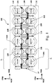
Fig. 1 is a quasi-cross-sectional view of a magnetically coupled wirelesspower transfer system 100 according to an example embodiment having atransmitter 102 and areceiver 104, each of which is cylindrically shaped similar to power receiver/transmitter magnet 402 depicted inFig. 4 . The quasi-cross-sectional view oftransmitter 102 is taken along transmitter magnetization-variation direction 150A and in anaxial direction 170 and the quasi-cross-sectional view ofreceiver 104 is taken receiver magnetization-variation direction 150B in anaxial direction 170. In other words,Fig 1 is not a true cross-section, but instead depicts a quasi-cross-sectional (i.e. circumferentially unraveled) view of a cylindricalpower transmitter magnet 102 unraveled alongmagnetization variation direction 150A and a quasi-cross-sectional (i.e. circumferentially unraveled) view of a cylindricalpower receiver magnet 104 unraveled alongmagnetization variation direction 150B. For brevity, further unraveled views shown in the drawings may be referred to herein as "cross-sections". - The
Fig. 1 wirelesspower transfer system 100 comprises a wirelesspower transmitter magnet 102 and wirelesspower receiver magnet 104 in close proximity and separated by anair gap 106. In theFig. 1 embodiment, the wirelesspower transmitter magnet 102 and wirelesspower receiver magnet 104 each comprise individual magneticfield generating units 108. In particular, wirelesspower transmitter magnet 102 comprises individual transmitter magnetic field generating units 108A and wirelesspower receiver magnet 104 comprises individual receiver magnetic field generating units 108B. For brevity, transmitter magnetic field generating units 108A and receiver magnetic field generating units 108B may be referred to more generally herein as magneticfield generating units 108 which may refer to one or both of transmitter magnetic field generating units 108A and receiver magnetic field generating units 108B. - Magnetic field generating units 108 (i.e. transmitter magnetic field generating units 108A and receiver magnetic field generating units 108B) may comprise permanent magnets such as, but not limited to, NdFeB, samarium cobalt, ferrite, magnetite and alnico magnets made up of combinations of iron, aluminum, nickel, cobalt, titanium and copper and commonly known by trade names such as Alni, Alcomax, Hycomax, Columax, and Ticonal, or combinations thereof. It will be considered in this disclosure that a permanent magnet is an object made from a material that is magnetized and creates its own persistent magnetic field.
- Each magnetic
field generating unit 108 may exhibit predominantly a single magnetization direction. In particular, each transmitter magnetic field generating unit 108A exhibits predominantly a correspondingfirst magnetization direction 120A, which may vary between transmitter magnetic field generating units 108A along transmitter magnetization-variation direction 150A.Transmitter variation direction 150A may comprise a circumferentially oriented magnetization-variation direction 150, as shown inFig. 4 . Thefirst magnetization directions 120A of transmitter magnetic field generating units 108A adjacent to one another in transmitter magnetization-variation direction 150A may be different from one another. Eachfirst magnetization direction 120A may also be orthogonal to a corresponding transmitter uniform-magnetization direction 160A, as depicted inFig. 1 . Each transmitter uniform-magnetization direction 160A may comprise a radially oriented uniform-magnetization direction 160 as shown inFig. 4 .First magnetization direction 120A of each transmitter magnetic field generating unit 108A may be constant along its corresponding transmitter uniform-magnetization direction 160A. In some embodiments,first magnetization direction 120A of each transmitter magnetic field generating unit 108A may be constant within each transmitter magnetic field generating unit 108A. - Similarly, each receiver magnetic field generating unit 108B exhibits predominantly a corresponding
second magnetization direction 120B which may vary between receiver magnetic field generating units 108B along receiver magnetization-variation direction 150B.Receiver variation direction 150B may comprise a circumferentially oriented magnetization-variation direction 150, as shown inFig. 4 . Thesecond magnetization directions 120B of receiver magnetic field generating units adjacent to one another in receiver magnetization-variation direction 150B may be different from one another. Eachsecond magnetization direction 120B may be orthogonal to a corresponding receiver uniform-magnetization direction 160B, as depicted inFig. 1 . Each receiver uniform-magnetization direction 160B may comprise a radially oriented uniform-magnetization direction 160 as shown inFig. 4 .Second magnetization direction 120B of each receiver magnetic field generating unit 108B may be constant along its corresponding receiver uniform-magnetization direction 160B. In some embodiments,second magnetization direction 120B of each receiver magnetic field generating unit 108B may be constant within each receiver magnetic field generating unit 108B. - In some embodiments, transmitter magnetization-
variation direction 150A is orthogonal to each of transmitter uniform-magnetization directions 160A and receiver magnetization-variation direction 150B is orthogonal to each of receiver uniform-magnetization directions 160B, as is the case in the cylindrical embodiment shown inFig. 4 , where magnetization-variation directions 150 are circumferentially oriented and uniform-magnetization directions 160 are radial. In some embodiments, transmitter magnetization-variation direction 150A and receiver magnetization-variation direction 150B may be located in planes which are parallel to one another. In some embodiments, these planes are not precisely parallel and may have normal vectors oriented at an angle between 0° and 15° relative to one another. - In some embodiments,
transmitter 102 andreceiver 104 are co-axial alongcylinder axis 170. In some embodiments, transmitter uniform-magnetization directions 160A are distributed circumferentially about cylinder axis 170 (Fig. 4 ) of the wireless power transmitter and extend fromcylinder axis 170 in radial directions and receiver uniform-magnetization directions 160B are distributed circumferentially aboutcylinder axis 170 of the wireless power receiver and extend fromcylinder axis 170 in radial directions. In some embodiments, transmitter magnetization-variation direction 150A extends circumferentially aboutcylinder axis 170 and the receiver magnetization-variation direction 150B extends circumferentially aboutcylinder axis 170 of the wireless power receiver (i.e. as depicted inFig. 4 in respect to uniform-magnetization direction 160 and magnetization-variation direction 150). - In some embodiments, the variation of first and
second magnetization directions first magnetization directions 120A of transmitter magnetic field generating units 108A may exhibit a first spatially periodic pattern along transmitter magnetization-variation direction 150A. The first spatially periodic pattern may have a first period comprising a number, λ1, of transmitter magnetic field generating units 108A. The variation ofsecond magnetization directions 120B of receiver magnetic field generating units 108B may exhibit a second spatially periodic pattern along receiver magnetization-variation direction 150B. The second spatially periodic pattern may have a second period comprising a number, λ2, of receiver magnetic field generating units 108B. - In some embodiments, the angular orientations of
first magnetization directions 120A of transmitter magnetic field generating units 108A adjacent to one another in transmitter magnetization-variation direction 150A vary about their corresponding transmitter uniform-magnetization directions 160A by a first angular offset, α1. In some embodiments, first angular offset, α1, is greater than 0° and varies depending on the number, λ1 of transmitter magnetic field generating units 108A in the first period. In some embodiments, the number, λ1, of transmitter magnetic field generating units 108A in the first period multiplied by the first angular offset, α1, is equal to 360°. - Similarly, in some embodiments, the angular orientations of
second magnetization directions 120B of receiver magnetic field generating units 108B adjacent to one another in receiver magnetization-variation direction 150B vary about their corresponding receiver uniform-magnetization directions 160B by a second angular offset, α2. In some embodiments, second angular offset, α2, is greater than 0° and varies depending on the number, λ2, of receiver magnetic field generating units 108B in the second period. In some embodiments, the number, λ2, of transmitter magnetic field generating units 108B in the second period multiplied by the second angular offset, α2, is equal to 360°. As illustrated in theFig. 1 embodiment, first angular offsets, α1, may be equal to second angular offsets, α2, although this is not necessary. In the illustrated embodiments, angular offsets, α1, α2, are constant within eachtransmitter magnet 102 and eachreceiver magnet 104 but this is not strictly necessary. In some embodiments, angular offsets, α1, α2, may vary within eachtransmitter magnet 102 and eachreceiver magnet 104 - In some embodiments, the number, λ1, of transmitter magnetic field generating units in the first period comprises three or more transmitter magnetic field generating units. For example, the first period may comprise three transmitter magnetic field generating units 108A with first angular offsets, α1, of approximately 120°. In another example, the first period may comprise four transmitter magnetic field generating units 108A with first angular offsets, α1, of approximately 90°, such as is illustrated in the
Fig. 1 embodiment. Similarly, in some embodiments, the number, λ2, of receiver magnetic field generating units in the second period comprises three or more receiver magnetic field generating units. For example, the second period may comprise three receiver magnetic field generating units 108B with second angular offsets, α2, of approximately 120°. In another example, the second period may comprise four receiver magnetic field generating units 108B with second angular offsets, α2, of approximately 90°, such as is illustrated in theFig. 1 embodiment. However, it should be understood that the number, λ1, of transmitter magnetic field generating units in the first period and the number, λ2, of receiver magnetic field generating units in the second period are not limited to three or four but may vary as discussed in more detail herein. - In some embodiments, the number of transmitter magnetic field generating units 108A in a wireless power transmitter is a positive integer multiple of the number, λ1, of transmitter magnetic field generating units 108A in a first period. Similarly, the number of receiver magnetic field generating units 108B in a wireless power receiver may be a positive integer multiple of the number, λ2, of receiver magnetic field generating units 108B in a second period.
- In some embodiments, at least one of the plurality of transmitter magnetic field generating units 108A comprises a permanent magnet and/or at least one of the receiver magnetic field generating units 108B comprises a permanent magnet. In some embodiments, at least one of the plurality of transmitter magnetic field generating units 108A comprises an electromagnetic coil and/or at least one of the receiver magnetic field generating units 108B comprises an electromagnetic coil.
- In some embodiments, the
first magnetization directions 120A, the first angular offsets, α1, and the number, λ1, of transmitter magnetic field generating units 108A in the first period, may be such that transmitter magnetic field generating units 108A comprise a Halbach array. Similarly, in some embodiments, thesecond magnetization directions 120B, the second angular offsets, α2, and the number, λ2, of receiver magnetic field generating units 108B in the second period may be such that receiver magnetic field generating units 108B comprise a Halbach array. - In the Halbach array embodiment depicted in the magnetically-coupled wireless
power transfer system 100 inFig. 1 , a plurality of magnets or magneticfield generating units 108 are arranged in such a way that adjacent magnetic field generating units 108 (from left to right in theFig. 1 view) ofwireless power transmitter 102 have magnetization directions 120 offset by about α1= -90° (about their corresponding uniform-magnetization directions 160). The adjacent magnetic field generating units 108 (from left to right in theFig. 1 view) of thewireless power receiver 104 have magnetization directions 120 offset by about α2=90° (about their corresponding uniform-magnetization directions 160B). The magneticfield generating units 108 directly aligned with each other across theair gap 106 within thewireless transmitter magnet 102 andwireless receiver magnet 104 and which have magnetization directions 120 oriented inaxial directions 170 have such magnetization directions 120 oriented in the same direction along axis 170 (seevertical direction 110 of theFig. 1 illustration). The magneticfield generating units 108 directly aligned with each other across theair gap 106 within thewireless transmitter magnet 102 andwireless receiver magnet 104 and which have magnetization directions 120 oriented in magnetization-variation directions 150 have such magnetization directions 120 oriented opposite to one another along their respective magnetization-variation directions 150 (seehorizontal direction 112 of theFig. 1 illustration). - As can be seen in the resulting magnetic flux lines in this
Fig. 1 embodiment, where each of thetransmitter magnet 102 andreceiver magnet 104 comprise Halbach arrays, the strongest magnetic fields are depicted by the bold dotted lines 114 and are located within theair gap 106 betweentransmitter magnet 102 andreceiver magnet 104. The weakest magnetic fields are located in theregions 116 on the opposite sides of thetransmitter magnet 102 andreceiver magnet 104 from theair gap 106. As a result, this Halbach arrangement of theFig. 1 embodiment enhances the magnetic field betweentransmitter magnet 102 andreceiver magnet 104. The enhanced magnetic field betweentransmitter magnet 102 andreceiver magnet 104 increases the efficiency of the wireless power transfer while limiting the intensity of stray magnetic fields on the outside of the transmitter and receiver magnets. - In an embodiment, the wireless power transmitter or the wireless power receiver in the magnetically-coupled wireless
power transfer system 100 inFig. 1 is equipped with a rotor (not expressly shown inFig. 1 ) to allow the wireless power receiver or transmitter to rotate about acorresponding axis 170. In another embodiment the wireless power transmitter is equipped with a rotor and the wireless power receiver is equipped with a rotor in the magnetically-coupled wirelesspower transfer system 100 inFig. 1 . In some embodiments, such rotors permit the wireless power transmitter and receiver to be rotatable about acommon axis 170. Such rotors may comprise a rotary assembly having an axle (as shown inFig. 4 ) or the like, allowed to rotate by, for example, a bushing or a bearing. -
Fig. 2 is a cross-sectional view of a magnetically coupled wirelesspower transfer system 200 according to an example embodiment.System 200 is substantially similar tosystem 100 except that first andsecond magnetization directions system 200 exhibits similar or identical features as described above in relation tosystem 100 and such similar or identical features would be apparent to those skilled in the art upon reading the description and understanding the figures herein. For example, and without limitation,system 200 may comprise a plurality of transmitter magneticfield generating units 208A and a plurality of receiver magneticfield generating units 208B (similar to transmitter magnetic field generating units 108A and receiver magnetic field generating units 108B). Each transmitter magneticfield generating unit 208A may exhibit predominantly a correspondingfirst magnetization direction 220A and each receiver magneticfield generating unit 208B may exhibit predominantly a correspondingsecond magnetization direction 220B. Thefirst magnetization directions 220A may vary in a transmitter magnetization-variation direction 150A and thesecond magnetization directions 220B may vary in a receiver magnetization-variation direction 150B. Each of thefirst magnetization directions 220A may be orthogonal to a corresponding transmitter uniform-magnetization direction 160A and each of thesecond magnetization directions 220B may be orthogonal to a corresponding receiver uniform-magnetization direction 160B. -
System 200 of theFig. 2 embodiment comprises a wirelesspower transmitter magnet 202 and wirelesspower receiver magnet 204 in close proximity and separated by anair gap 206. In theFig. 2 embodiment, the plurality of individual magnetic field generating units 208 have magnetization directions 220 oriented in opposite directions to those found in the wirelesspower transfer system 100 inFig. 1 (see magnetization directions 220 having vertical 210 and horizontal 212 orientations in theFig. 2 view). - In the embodiment of a magnetically coupled wireless power transfer system in
Fig. 2 , the strongest magnetic fields are located within theair gap 206 as depicted by the bold dotted magnetic flux lines 214. This enhances the power transfer efficiency while the weakest magnetic fields are located in theregions 216 on the opposite sides of thetransmitter magnet 202 andreceiver magnet 204 from theair gap 206. If permanent magnets such as, but not limited to, NdFeB, samarium cobalt, ferrite, magnetite and alnico magnets comprised of combinations of iron, aluminum, nickel, cobalt, titanium and copper and commonly known by trade names such as Alni, Alcomax, Hycomax, Columax, and Ticonal, or combinations thereof were used to construct the wirelesspower transfer systems Figs. 1 and2 , respectively, the alignment of the individual magnetic field generating units would simply need to be reversed. - The Halbach arrays in the wireless power transfer systems illustrated in
Figs. 1 and2 may be constructed using permanent magnets such as, but not limited to, NdFeB, samarium cobalt, ferrite, magnetite and alnico magnets comprised of combinations of iron, aluminum, nickel, cobalt, titanium and copper and commonly known by trade names such as Alni, Alcomax, Hycomax, Columax, and Ticonal, or combinations thereof. Another embodiment may be envisioned where the permanent magnets may be replaced by coils. Using coils in the place of permanent magnets may offer at least three distinct advantages. Firstly, rare earth magnets can be rather expensive in cost. A low cost alternative to permanent magnets would be preferred to keep manufacturing costs low. Secondly, rare earth magnets are denser and heavier in weight than coils. Thirdly, it is much easier to change the magnetization direction in coils than permanent magnets by simply reversing the current flow within the coils. - In an embodiment, the wireless power transmitter or the wireless power receiver in the magnetically-coupled wireless
power transfer system 200 inFig. 2 is equipped with a rotor (not expressly shown inFig. 2 ) to allow the wireless power receiver or transmitter to rotate about acorresponding axis 170. In another embodiment the wireless power transmitter is equipped with a rotor and the wireless power receiver is equipped with a rotor in the magnetically-coupled wirelesspower transfer system 200 inFig. 2 . In some embodiments, such rotors permit the wireless power transmitter and receiver to be rotatable about acommon axis 170. Such rotors may comprise a rotary assembly having an axle (as shown inFig. 4 ) or the like, allowed to rotate by, for example, a bushing or a bearing. -
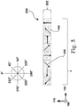
Fig. 3 is a cross-sectional view of a wireless power transmitter magnet 303, where each field generating unit 308A comprises one or morecorresponding coils 302 according to a particular embodiment.Fig. 3 shows power transmitter magnet 303 in a first state 304 and a second state 310. The Fig. power transmitter magnet 303 may comprise part of a wireless induction-basedpower transfer system 300, wherein alternating the current in thecoils 302 of power transmitter magnet 303 induces corresponding current in one or more proximate receiver coils (not shown inFig. 3 ). Power transmitter magnet 303 ofsystem 300 exhibits some similarities to thepower transmitter magnet 102 of theFig. 1 embodiment. For example, and without limitation, power transmitter magnet 303 may comprise a plurality of transmitter magnetic field generating units 308A. Each transmitter magnetic field generating unit 308A may exhibit predominantly a correspondingfirst magnetization direction 320A (which may vary depending on the direction of current flow through its corresponding coil 302). Thefirst magnetization directions 320A may vary in a transmitter magnetization-variation direction 150A. Each of thefirst magnetization directions 320A may be orthogonal to a corresponding transmitter uniform-magnetization direction 160A. In some embodiments, the one or more receiver coils ofsystem 300 may be arranged in a manner similar to that of transmitter magnet 303 with receiver coil units corresponding to thefield generating units 308 of transmitter magnet 303, although this is not necessary. WhileFig. 3 depicts a wireless power transmitter 303, a wireless power receiver could be provided with field generating units arranged in a manner similar to thefield generating units 308 of transmitter magnet 303. - In some embodiments, coils 302 of transmitter 303 may be electrically connected in series. In some embodiments, coils 302 may be fabricated from a single wire. In the
Fig. 3 embodiment of wireless power transmitter 303 (or a similarly configured wireless power receiver), the electrical current-carryingcoils 302 may be arranged such that current flow throughcoils 302 in a first direction causes themagnetization directions 320A of transmitter 303 to have the Halbach arrangement 304 (shown at the top ofFig. 3 ) and such that current flow throughcoils 302 in a second (opposing) direction causes themagnetization directions 320A of transmitter 303 to have the Halbach arrangement 310 (shown at the bottom ofFig. 3 ). Alternating the current flow between these first and second directions creates magnetic field flux which is concentrated on one side of transmitter 303 and which varies between theFig. 3 configurations 304, 310. This concentrated and varying magnetic field can induce current in the receiver coils ofsystem 300. - The magnetic induction wireless
power transfer system 300 of theFig. 3 embodiment may comprise a wireless power transmitter 303 having a plurality of field generating units 308A, each of which may further comprise one or more electrical current-carryingcoils 302. A wireless power receiver (not shown inFig. 3 ) may comprise one or more receiver coils. In some embodiments, a wireless power receiver may comprise a plurality of magnetic field generating units, each of which may further comprise one or more electrical current-carrying coils, and which may have an arrangement similar to that of transmitter 303. An air gap may separate the wireless power transmitter 303 and wireless power receiver. The plurality of electrical current-carryingcoils 302 in wireless power transmitter 303 and the wireless power receiver may be arranged in an array such that the magnetic field strength is greater in the air gap between the wireless power transmitter and wireless power receiver than the magnetic field strength outside of the air gap separating the wireless power transmitter and wireless power receiver. - The
coils 302 in transmitter 303 and the receiver may be arranged such that the magnetization directions of adjacent field-generating units (in the transmitter and/or the receiver) are angularly offset from one another. In the particular case of the illustrated embodiment, adjacent field-generating units 308A exhibit angular offsets, α, of about 90° about their corresponding uniform-magnetization directions 160A. The alternating current going into eachcoil 302 in transmitter 303 may be phased relative to the current inother coils 302 to ensure that the magnetic field directions 320, which may be 306 (vertical in the illustrated view) and 308 (horizontal in the illustrated view) produced by the transmittingcoils 302 achieve strong magnetic field (depicted by bold dotted lines) on one side compared to the magnetic field (depicted by thin dotted lines) on the other (similar to as shown inFig. 1 ). This can be achieved, for example, by connecting the ends of eachadjacent coil 302 in series such that either state 304 or 310 is achieved when the current reverses direction in the transmitter as shown inFig. 3 . Insystem 300, the strongly one-sided time varying magnetic field produced by transmitter 303 induces a time-varying current in one or more receiver coils (which may comprise a set of receiver coils having an arrangement similar to thecoils 302 of transmitter 303) and which are located on the side of transmitter 303 having the stronger field and potentially separated from transmitter 303 by an air gap. Other magnetization patterns may be possible than those listed inFig. 3 such as where the angular offset, α, may range from about 1° to about 90° or more. -
Fig. 4 is a schematic view of a wireless power transmitter or receiver magnet according to an example embodiment.Fig 4 . depicts an exemplary non-unraveled view of a wirelesspower transmitter magnet 402 or receiver magnet. Any of the transmitter and/or receivers of the embodiments described in connection withFigs. 1-3 and5-8 may have the non-unraveled configuration shown inFig. 4 , although this is not necessary.System 400 represents an exemplary embodiment of a wirelesspower transmitter magnet 402 or receiver magnet that could exhibit any of the properties described above or below in relation to a wireless power transmitter magnet (i.e.magnet 104 or any other transmitter magnet or coil herein) or a wireless power receiver magnet (i.e.magnet 102 or any other receiver magnet or coil herein).System 400 may be substantially similar to system 100 (or 200 or any other embodiment herein), although shown from a different perspective. In other respects,system 400 may exhibit similar or identical features as described above in relation tosystem 100 and such similar or identical features would be apparent to those skilled in the art upon reading the description and understanding the figures herein. For example, and without limitation,power transmitter magnet 402 ofsystem 400 comprises a plurality of magnetic field generating units 408 (similar to transmitter magnetic field generating units 108A and receiver magnetic field generating units 108B). Each magneticfield generating unit 408 may exhibit predominantly acorresponding magnetization direction 420. Themagnetization directions 420 may vary in a magnetization-variation direction 150. Each of themagnetization directions 420 may be orthogonal to a corresponding uniform-magnetization direction 160. - In some embodiments of magnetic coupling wireless power transfer charging systems, rotation of coupled magnets creates a current whereby power can be transferred from a power transmitter to a receiver.
Fig. 4 is an illustration of an embodiment of a wirelesspower transmitter magnet 402 or receiver magnet in a disk-like (or cylindrical) shape constructed of a plurality of individual petal-shaped, pie-shaped or wedge-shaped magneticfield generating units 408, which may comprise permanent magnets or coil-based magnets. In this embodiment, petal-shaped individual magneticfield generating units 408 each with aspecific magnetization direction 420 are linked together or otherwise abut one another.Lines 404 denote the location of demarcation where the individual magneticfield generating units 408 are linked side-by-side. - Additionally in the
Fig. 4 embodiment, the magnets are linked to an optionalinner core 406 for further stabilization, althoughcore 406 is not necessary.System 400 may further comprise arotor 418 operative connected totransmitter magnet 402 by whichtransmitter magnet 402 may be rotated about axis 170 (e.g. with a motor or some other mover). Additionally or alternatively, thetransmitter 402 may be rotated in the magnetic-variation direction 150 by coils carrying alternating current (AC) placed behind the magnets (e.g. coils similar tocoils 706 inFig. 7 ). Although the embodiment inFig. 4 shows thetransmitter magnet 402 being depicted as a disk, other non-limiting shapes may be used such as, for example, cylindrical or spherical. The magneticfield generating units 408 may be comprised of permanent magnets such as, but not limited to, NdFeB, samarium cobalt, ferrite, magnetite and alnico magnets made up of combinations of iron, aluminum, nickel, cobalt, titanium and copper and commonly known by trade names such as Alni, Alcomax, Hycomax, Columax, and Ticonal, or combinations thereof. In theFig. 4 system 400, a receiver magnet (not shown) may be provided and may have properties similar to transmitter magnet 402 (except that the receiver magnet is not drivingly rotated). -
Fig. 5 is a cross-sectional view of a wireless power transmitter orreceiver magnet 502 according to an example embodiment which may form part of awireless power system 500 according to an example embodiment.System 500 is substantially similar tosystem 100 except that the angular offset, α, of themagnetization directions 520 is smaller than insystem 100. In other respects,system 500 exhibits similar or identical features as described above in relation tosystem 100 and such similar or identical features would be apparent to those skilled in the art upon reading the description and understanding the figures herein. For example, and without limitation,system 500 comprises a plurality of magnetic field generating units 508 (similar to transmitter magnetic field generating units 108A and receiver magnetic field generating units 108B). Each magneticfield generating unit 508 may exhibit predominantly a corresponding magnetization direction. Themagnetization directions 520 may vary in a magnetization-variation direction 150. Each of themagnetization directions 520 may be orthogonal to a corresponding uniform-magnetization direction 160. Themagnetization directions 520 may exhibit a spatially periodic pattern having a number, λ, of magneticfield generating units 508 in each period. - It may be envisioned that other Halbach arrangement embodiments may be used that differ from those described in
Figs. 1 and2 that may also lead to enhancement of the magnetic field on one side of a transmitter or receiver magnet while minimizing or substantially reducing the magnetic field on the opposite side of the transmitter or receiver. The embodiment illustrated inFig. 5 is a depiction of a cross-section (i.e. an unraveled view) of a wireless transmitter orreceiver magnet 502 comprised of a plurality of individual magneticfield generating units 508 in an arrangement similar to that found inFig. 4 (the rotor is not shown). Themagnetization directions 520 between adjacent individual magneticfield generating units 508, comprising permanent magnets or coils or combinations thereof, within the wireless power transmitter or receiver exhibit angular offsets, α, of about -45° about their corresponding uniform-magnetization directions. The magneticfield generating units 508 may be comprised of permanent magnets such as, but not limited to, NdFeB, samarium cobalt, ferrite, magnetite and alnico magnets made up of combinations of iron, aluminum, nickel, cobalt, titanium and copper and commonly known by trade names such as Alni, Alcomax, Hycomax, Columax, and Ticonal, or combinations thereof. The wireless power transmitter orreceiver magnet embodiment 502 depicted inFig. 5 may further comprise a rotor. The rotor may comprise a rotary assembly having an axle or the like, allowed to rotate by, for example, a bushing or a bearing. -
Fig. 6 is a cross-sectional view of a wireless power transmitter orreceiver magnet 602 according to an example embodiment which may form part of awireless power system 600 according to an example embodiment.System 600 is substantially similar tosystem 100 except that the angular offset, α, of themagnetization directions 620 is smaller than insystem 100. In other respects,system 600 exhibits similar or identical features as described above in relation tosystem 100 and such similar or identical features would be apparent to those skilled in the art upon reading the description and understanding the figures herein. For example, and without limitation,system 600 comprises a plurality of magnetic field generating units 608 (similar to transmitter magnetic field generating units 108A and receiver magnetic field generating units 108B). Each magneticfield generating unit 608 may exhibit predominantly a corresponding magnetization direction. Themagnetization directions 620 may vary in a magnetization-variation direction 150. Each of themagnetization directions 620 may be orthogonal to a corresponding uniform-magnetization direction 160. Themagnetization directions 620 may exhibit a spatially periodic pattern having a number, λ, of magneticfield generating units 608 in each period. - Another Halbach array embodiment may be envisioned as illustrated in
Fig. 6 for use in a wireless power transfer system.Fig. 6 is a depiction of a cross-section of a wireless transmitter orreceiver magnet 602 comprised of a plurality of individual magneticfield generating units 608 in an arrangement similar to that found inFig. 4 (the rotor is not shown). Themagnetization directions 620 between adjacent individual magneticfield generating units 608 comprised of permanent magnets or coils or combinations thereof within the wireless power transmitter or receiver exhibit angular offsets, α, of about -30° about their corresponding uniform-magnetization directions. The magneticfield generating units 608 may be comprised of permanent magnets such as, but not limited to, NdFeB, samarium cobalt, ferrite, magnetite and alnico magnets made up of combinations of iron, aluminum, nickel, cobalt, titanium and copper and commonly known by trade names such as Alni, Alcomax, Hycomax, Columax, and Ticonal, or combinations thereof. The wireless power transmitter orreceiver magnet embodiment 602 depicted inFig. 6 may further comprise a rotor. The rotor may comprise a rotary assembly having an axle or the like, allowed to rotate by, for example, a bushing or a bearing. - In the Halbach array embodiments for wireless power transfer systems described herein, they have been limited to angular offsets, α, of about 30°, 45° and 90° about their corresponding uniform-magnetization directions (i.e. uniform-magnetization directions 160). This has been for purposes of description only and should not be considered limitative. In principle there could be an infinite number of angular offsets, α, in magnetization directions from about ±1° to about ±120° but for practical reasons these may be limited. Furthermore, the magnetization directions aren't required to be vertical or horizontal. It is desired that the magnetization directions "rotate" in different directions for the transmitter and receiver, thereby causing the magnetic field in the gap to become more sinusoidal and hence the induced current in the coil becomes more sinusoidal.
- For magnetically coupled wireless power transfer systems, the transmitter magnet rotor may be driven by a motor and rotated to create a first time-varying magnetic field. This induces rotation in a receiver magnet across a gap to produce a second time-varying magnetic field. The transfer of power across the gap is through magnetic coupling. The second time varying magnetic field induces electrical current in coils around the receiver magnets. An alternative wireless power transfer system that reduces or even eliminates the need for a motor which in turn would lead to a lower cost system with lower maintenance is described below.
-
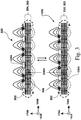
Fig. 7 is a cross-sectional view of a wirelesspower transfer system 700 comprising individual magnetic field generating units made up of both permanent magnets and stationary coils according to an example embodiment.System 700 is substantially similar tosystem 100 except that coils 706 and 712 have been added, as described below. In other respects,system 700 exhibits similar or identical features as described above in relation tosystem 100 and such similar or identical features would be apparent to those skilled in the art upon reading the description and understanding the figures herein. For example, and without limitation,system 700 may comprise a plurality of transmitter magneticfield generating units 708A and a plurality of receiver magneticfield generating units 708B (similar to transmitter magnetic field generating units 108A and receiver magnetic field generating units 108B). Each transmitter magneticfield generating unit 708A may exhibit predominantly a correspondingfirst magnetization direction 720A and each receiver magneticfield generating unit 708B may exhibit predominantly a correspondingsecond magnetization direction 720B. Thefirst magnetization directions 720A may vary in a transmitter magnetization-variation direction 150A and thesecond magnetization directions 720B may vary in a receiver magnetization-variation direction 150B. Each of thefirst magnetization directions 720A may be orthogonal to a corresponding transmitter uniform-magnetization direction 160A and each of thesecond magnetization directions 720B may be orthogonal to a corresponding receiver uniform-magnetization direction 160B. - The embodiment illustrated in
Fig. 7 is a cross-section of a wirelesspower transfer system 700 comprises a combination of a plurality of permanent magnets in a Halbach array and stationary coils. The wireless power transfer system comprises awireless power transmitter 702 that further may comprise a plurality of transmitter magneticfield generating units 708A aligned in the form of a Halbach transmitter magnet (rotor not shown) where the horizontal andvertical magnetization directions 720A of the individual transmitter magneticfield generating units 708A exhibit angular offsets, α, of about -90° about their corresponding uniform-magnetization directions 160A. Placed below the plurality of transmitter magneticfield generating units 708A is a plurality of stationary electrical current-carryingcoils 706. An alternating electrical current may be passed through stationary electrical current-carryingcoils 706 to induce rotational motion in the transmitter magneticfield generating units 708A. - The wireless
power transfer system 700 further comprises awireless power receiver 704 that comprises a plurality of receiver magneticfield generating units 708B aligned in the form of a Halbach receiver magnet (rotor not shown). The horizontal andvertical magnetization directions 720B of the individual receiver magneticfield generating units 708B are offset by an angular offset, α, of about +90° about their corresponding uniform-magnetization directions, or opposite to that found in the Halbach transmitter magnet. The vertical magnetization directions of the Halbach receiver and transmitter magnets are aligned in the same direction while the horizontal magnetization directions of the Halbach transmitter and receiver magnets are in opposite directions. Placed between the plurality of receiver magneticfield generating units 708B in the Halbach receiver magnet (rotor not shown) of the wireless power receiver and the plurality of transmitter magneticfield generating units 708A in the Halbach transmitter magnet (rotor not shown) of the wireless power transmitter is a plurality of stationary electrical current-carrying power receiver coils 712 in which an alternating current is induced by the enhanced magnetic field caused by rotation of the receiver and transmitter magnetic arrays around an axis (i.e. axis 170, not shown). It is preferred that the stationary receiver coils 712 are located in close proximity to the Halbach receiver magnet as the magnetic field is strongest. Thewireless power transmitter 702 andwireless power receiver 704 are separated by anair gap 714. Within theair gap 714 are located the strongest magnetic fields of the Halbach transmitter and receiver magnets. In theregions 716 on the opposite sides of the Halbach transmitter and receiver magnets from theair gap 714 is located the area where the magnetic field is substantially reduced relative to the magnetic fields within theair gap 714. This Halbach arrangement embodiment substantially reduces stray magnetic fields and enhances the magnetic fields within theair gap 714 in order to enhance the efficiency of the power transmission. - Other Halbach arrangement embodiments may be envisioned for use in wireless power transfer systems using combinations of permanent magnets and coils as explained herein and illustrated in the non-limiting example in
Fig. 7 . For example, magnetization directions of the individual magnetic field generating units within the Halbach transmitter and receiver magnets may exhibit angular offsets, α, of about -45° to about -30° about their corresponding uniform-magnetization directions as described inFigs. 5 and6 , respectively. Other angular offsets, α, of varying angles may be used from about ±1° to about ±90° or more. The magneticfield generating units - In an embodiment, the wireless power transmitter in the wireless
power transfer system 700 inFig. 7 further comprises a rotor. In another embodiment, the wireless power receiver in the wirelesspower transfer system 700 inFig. 7 further comprises a rotor. In another embodiment, both the wireless power transmitter comprises a rotor and the wireless power receiver comprises a rotor in the wirelesspower transfer system 700 depicted inFig. 7 . The rotor may comprise a rotary assembly having an axle or the like, allowed to rotate by, for example, a bushing or a bearing. - The wireless
power transfer system 700 embodiment shown inFig. 7 may be operated as follows. Changing the current in the stationary transmitter coils 706 creates a magnetic field that induces the rotation/movement of the Halbach transmitter magneticfield generating units 708A which produces a strong first time-varying magnetic field. This first magnetic field couples with the Halbach receiver magneticfield generating units 708B which rotate/move and produce a second time varying magnetic field that in turn induces a time-varying current in the stationary receiver coils 712 located in theair gap 714 where the magnetic field is the strongest. This results in power being transferred from thewireless power transmitter 702 to thewireless power receiver 704. -
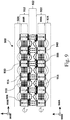
Fig. 8 is a cross-section of a wirelesspower transfer system 800 comprising a combination of a plurality of moveable permanent magnets in a Halbach array and stationary coils according to an example embodiment.System 800 is substantially similar tosystem 100 except that rotatingwireless power transmitter 102 has been replaced with a stationary wireless power transmitter 802 (similar to that ofFig. 2 ). In other respects,system 800 exhibits similar or identical features as described above in relation tosystem 100 and such similar or identical features would be apparent to those skilled in the art upon reading the description and understanding the figures herein. For example, and without limitation,system 800 may comprise a plurality of transmitter magneticfield generating units 808A and a plurality of receiver magneticfield generating units 808B (similar to receiver magnetic field generating units 108B). Each transmitter magneticfield generating unit 808A may exhibit predominantly a corresponding first magnetization direction 820A and each receiver magneticfield generating unit 808B may exhibit predominantly a correspondingsecond magnetization direction 820B. The first magnetization directions 820A may vary in a transmitter magnetization-variation direction 150A and thesecond magnetization directions 820B may vary in a receiver magnetization-variation direction 150B. Each of the first magnetization directions 820A may be orthogonal to a corresponding transmitter uniform-magnetization direction 160A and each of thesecond magnetization directions 820B may be orthogonal to a corresponding receiver uniform-magnetization direction 160B. - The wireless
power transfer system 800 inFig. 8 is comprised of awireless power transmitter 802 that is further comprised of a plurality of stationary electrical current-carryingcoils 804 through which a time-varying current may be passed to create a first time varying magnetic field in a Halbach manner where the resulting horizontal and vertical magnetization directions exhibit angular offsets, α, of about -90° about their corresponding uniform-magnetization directions. The wirelesspower transfer system 800 further comprises awireless power receiver 806 that is comprised of a plurality of magneticfield generating units 808B aligned in the form of a Halbach receiver magnet (rotor not shown) where the horizontal andvertical magnetization directions 820B of the individual receiver magneticfield generating units 808B exhibit angular offsets, α, of about +90° about their corresponding uniform-magnetization directions, or opposite to that found in the Halbach transmitter magnet. The vertical magnetization directions of the Halbach receiver magnet and magnetic field generated by the stationary transmitter coils may be aligned in the same direction while the horizontal magnetization directions are in opposite directions. The magneticfield generating units 808B may be comprised of permanent magnets such as, but not limited to, NdFeB, samarium cobalt, ferrite, magnetite and alnico magnets made up of combinations of iron, aluminum, nickel, cobalt, titanium and copper and commonly known by trade names such as Alni, Alcomax, Hycomax, Columax, and Ticonal, or combinations thereof. - Placed between the plurality of magnetic
field generating units 808B in the Halbach receiver magnet of the wireless power receiver and the plurality ofstationary coils 804 in the Halbach transmitter of thewireless power transmitter 802 is a plurality of stationary power receiver coils 810 where a current is induced. It is preferred that the stationary receiver coils 810 are located close to the magnetic field generating units 808 as the magnetic field is strongest. Thewireless power transmitter 802 andwireless power receiver 806 are in close proximity and separated by anair gap 812. Within theair gap 812 is located the strongest magnetic fields (represented by bold dotted lines) of theHalbach power transmitter 802 andreceiver 806. In theregions 814 on the opposite sides of the power transmitter and receivers from theair gap 812 are located in the area where the magnetic field is substantially reduced relative to the fields within theair gap 812. This Halbach arrangement embodiment substantially reduces stray magnetic fields and enhances the magnetic fields within theair gap 812 in order to enhance the efficiency of the power transmission. Other Halbach arrangement embodiments may be envisioned to use in wireless power transfer systems using combinations of permanent magnets and coils as explained herein and illustrated in the non-limiting example inFig. 8 . For example, magnetization directions 820 of the individual magnetic field generating units within the Halbach transmitter and receiver may exhibit angular offsets, α, of about -45° to about -30° about their corresponding uniform-magnetization directions as described inFigs. 5 and6 , respectively. Other angular offsets, α, of varying angles may be used. In an embodiment, the wireless power receiver further consists of a rotor in the wirelesspower transfer system 800 depicted inFig. 8 . - The wireless
power transfer system 800 embodiment shown inFig. 8 may be operated as follows. Applying a current, such as an alternating current, in the stationary electrical current-carrying transmitter coils 804 creates a first time varying magnetic field in a Halbach arrangement where each individual coil has an angular offset, α. This first time varying magnetic field magnetically couples onto the Halbach magnetic field generating units (permanent magnets) 808B (rotor not shown) in the wirelesspower transfer receiver 806. This induces motion/rotation of the magneticfield generating units 808B. This motion/rotation generates a secondary time-varying magnetic field resulting in electrical current being induced in thecoils 810 adjacent to the magneticfield generating units 808B. - In another embodiment related to wireless
power transfer system 800 inFig. 8 , the wireless power transmitter consists of stationary electrical current-carrying coils and a plurality of moveable permanent magnets in a Halbach array and a rotor. The wireless power receiver comprises stationary current-carrying coils only. Applying a current to the stationary coils in the transmitter creates a first time varying magnetic field in a Halbach arrangement which induces motion/rotation of the magnetic field generating units in the transmitter. This motion/rotation generates a secondary time-varying magnetic field resulting in electrical current being induced in the coils in the wireless power receiver. -
Fig. 9 is a cross-section (taken in a plane orthogonal to uniform-magnetization directions power transfer system 900 comprising a combination of a plurality of moveable permanent magnets and stationary coils according to an example embodiment.System 900 comprises acylindrical transmitter magnet 908A with an axial transmitter magnetization-variation direction 950A about whichmagnets 908A are rotated.System 900 also comprises acylindrical receiver magnet 908B with an axial receiver magnetization-variation direction 950B about whichmagnets 908B are rotated. Rotatingmagnets System 900 is similar tosystem 100 except as described herein. In other respects,system 900 exhibits similar or identical features as described above in relation tosystem 100 and such similar or identical features would be apparent to those skilled in the art upon reading the description and understanding the figures herein. For example, and without limitation,system 900 may comprise a plurality of transmitter magneticfield generating units 908A and a plurality of receiver magneticfield generating units 908B (similar to transmitter magnetic field generating units 108A and receiver magnetic field generating units 108B, although different in shape). Each transmitter magneticfield generating unit 908A may exhibit predominantly a corresponding first magnetization direction 920A and each receiver magneticfield generating unit 908B may exhibit predominantly a corresponding second magnetization direction 920B. The first magnetization directions 920A may vary in a transmitter magnetization-variation direction 950A and the second magnetization directions 920B may vary in a receiver magnetization-variation direction 950B. Each of the first magnetization directions 920A may be orthogonal to a corresponding transmitter uniform-magnetization direction 960A and each of the second magnetization directions 920B may be orthogonal to a corresponding receiver uniform-magnetization direction 960B. - The wireless power transfer system comprises a
wireless power transmitter 902 that further may comprise a plurality of transmitter magneticfield generating units 908A. Magneticfield generating units 908A comprised ofpermanent magnets 906 interleaved with stationary electrical current-carrying coils 918A. Thepermanent magnets 906 may be comprised of permanent magnets such as, but not limited to, NdFeB, samarium cobalt, ferrite, magnetite and alnico magnets made up of combinations of iron, aluminum, nickel, cobalt, titanium and copper and commonly known by trade names such as Alni, Alcomax, Hycomax, Columax, and Ticonal, or combinations thereof. - The
permanent magnets 906 may be in a cylindrical shape (with an axis parallel tomagnetic variation direction 950A) interconnected by a common shaft (not shown) that passes through the stationary coils 918A. Thepermanent magnets 906 may rotate about the magnetization-variation direction 950A and are further surrounded bycoils 940. Magnet rotation is induced by application of a current in thecoils 940 surrounding thepermanent magnets 906. The wirelesspower transfer system 900 further comprises awireless power receiver 912 that further comprises a plurality of receiver magneticfield generating units 908B comprised ofpermanent magnets 916 interleaved with stationary coils 918B. Thepermanent magnets 916 may be in a cylindrical shape interconnected by a common shaft (not shown) that passes through the stationary electrical current-carrying coils 918B. The magnets may rotate about magnetization-variation direction 950B and are further surrounded bycoils 930. Thewireless power transmitter 902 andreceiver 912 are further separated by anair gap 922. - In the example in
Fig. 9 , the magnetization directions of the plurality of magneticfield generating units 908A of thewireless power transmitter 902 exhibit angular offsets, α, of about - 90° about their corresponding uniform-magnetization directions 960. The magnetization directions 920 of the magneticfield generating units 908B of thewireless power receiver 912 exhibit angular offsets, α, of about +90° about their corresponding uniform-magnetization directions. Other angular offsets, α, of magnetization directions of various angles may be used. Thepermanent magnets 916 may be comprised of permanent magnets such as, but not limited to, NdFeB, samarium cobalt, ferrite, magnetite and alnico magnets made up of combinations of iron, aluminum, nickel, cobalt, titanium and copper and commonly known by trade names such as Alni, Alcomax, Hycomax, Columax, and Ticonal, or combinations thereof. - In an embodiment, the wireless power transmitter in the wireless
power transfer system 900 inFig. 9 further comprises a rotor. In another embodiment, the wireless power receiver in the wirelesspower transfer system 900 inFig. 9 further comprises a rotor. In another embodiment, both the wireless power transmitter comprises a rotor and the wireless power receiver comprises a rotor in the wirelesspower transfer system 900 depicted inFig. 9 . The rotor may comprise a rotary assembly having an axle or the like parallel with magnetization-variation directions - The wireless
power transfer system 900 embodiment shown inFig. 9 may be operated as follows. Thestationary coils 918A and 940 in thewireless power transmitter 902 are energized by alternating current to produce a time varying magnetic field that rotates thepermanent magnets 906 connected by a common shaft on an axis parallel to magnetization-variation direction 950B. Thecoils 918A and 940 are interconnected and electrical current through the adjacent coils 918A will flow in a way to maintain a Halbach magnetic field with magnetic flux directed towards the wireless power receiver as much as possible. This forms the first time-varying magnetic field with magnetic field focused towards thereceiver 912. Thepermanent magnets 916 linked by a common shaft in a direction parallel to magnetization-variation direction 950A with interleaved coils 918B on an axis parallel to magnetization-variation direction 950A in thewireless power receiver 912 rotates through magnetic coupling with the first time-varying magnetic field. This motion generates a second time-varying magnetic field which induces electrical current through thecoils 930 around thepermanent magnets 916. Thesecoils 930 are connected to the adjacent (interleaved) coils 918B, which produces a third time-varying magnetic field that cancels and reinforces the second time-varying magnetic field such that a second Halbach magnetic field is formed at the receiver. The magnetic flux is focused towards the wireless power transmitter with the highest magnetic fields within theair gap 922. In theregions 924 on the opposite sides of the power transmitter and receivers from theair gap 922 are located in the area where the magnetic field is substantially reduced relative to the fields within theair gap 922. This Halbach arrangement may substantially reduce stray magnetic fields and enhances the magnetic fields within theair gap 922 in order to enhance the efficiency of the power transmission. - The invention described herein may be used in wireless power transmission systems based on the Faraday effect and Halbach arrays to increase the efficiency of the power transmission and make safer for consumers by reducing stray magnetic fields. Said wireless power transmission systems may be used in applications such as, but not limited to, boats, automobiles, trucks, delivery vehicles, transit buses, ships, aircraft, motorcycles, electric bicycles, consumer devices and medical implants and other devices. A further advantage of the invention described may be the reduction in cost and in weight by eliminating the need for soft-iron cores in the coils. Lastly, the systems described herein may be scalable to more magnets and/or coils to produce different power ranges.
- As will be apparent to those skilled in the art in the light of the foregoing disclosure, many alterations and modifications are possible in the practice of this invention without departing from the scope thereof. For example:
- Various embodiments described herein (
e.g. systems - In some instances, this description and the accompanying claims use terms generally to describe directions, orientations, shapes, relationships (e.g. equalities) and/or the like. For example, transmitter magnetic field generating unit may have a first magnetization direction that is orthogonal to a transmitter magnetization-variation direction. Such directions, orientations, shapes, relationships and/or the like should be considered to accommodate the specified directions, orientations, shapes, relationships and/or the like and/or relatively small deviations (from an operational or engineering perspective) from the specified directions, orientations, shapes, relationships and/or the like.
- In some instances, this description and the accompanying claims refer to transmitter magnetic field generating units using the
reference numerals 108A, 208A, 308A etc. and to receiver magnetic field generating units using thereference numerals 108B, 208B, 308B etc. It should be understood from this description that magneticfield generating units variation directions 150 and like reference numerals may refer to transmitter magnetization-variation directions or receiver magnetization-variation directions. Similarly, this naming principle may apply to magnetization directions (e.g. magnetization directions magnetization directions 160 and like reference numerals) and generally herein. - In some instances, this description may refer to horizontal and vertical magnetization directions in the figures. This is done for convenience. It should be understood that a horizontal magnetization direction is any magnetization direction that, when broken down into horizontal (in the page) and vertical (in the page) components, exhibits a horizontal component of magnitude greater than zero and vertical magnetization directions are magnetization directions that are substantially vertical (in the page).
- In some instances, this description and the accompanying claims refer to the horizontal and vertical directions. This is done for convenience and refers merely to the horizontal and vertical directions in
Figs. 1 to 9 . It should be understood that entire systems (e.g. systems - In some instances, this description and the accompanying claims refer to receiver magnetic field generating units. Where the receiver field generating units comprise coils, this reference is a matter of nomenclature and doesn't necessarily mean that the receiver magnetic field generating units are driven to generate corresponding magnetic fields. In practice, the receiver magnetic field generating units may instead have currents induced therein, which induced currents may in turn create corresponding magnetic fields.
- While a number of exemplary aspects and embodiments have been discussed above, those of skill in the art will recognize certain modifications, permutations, additions and subcombinations thereof. It is therefore intended that the scope of protection is defined by the appended claims.
Claims (10)
- A magnetically-coupled wireless power transfer system (100, 200, 300, 400, 500, 600, 700, 800, 900), comprising:a wireless power transmitter (102, 702) further comprising a plurality of transmitter magnetic field generating units (108A, 208A, 308A, 408, 508, 608, 708A, 808A, 908A);a first time-varying magnetic field created by the wireless power transmitter (102, 702);a wireless power receiver (104, 704) further comprising a plurality of receiver magnetic field generating units (108B, 208B, 308B, 408, 508, 608, 708B, 808B, 908B), the plurality of receiver magnetic field generating units (108B, 208B, 308B, 408, 508, 608, 708B, 808B, 908B) located in the vicinity of the first time-varying magnetic field, the plurality of receiver magnetic field generating units (108B, 208B, 308B, 408, 508, 608, 708B, 808B, 908B) magnetically couplable to the plurality of transmitter magnetic field generating units (108A, 208A, 308A, 408, 508, 608, 708A, 808A, 908A) and the plurality of receiver magnetic field generating units (108B, 208B, 308B, 408, 508, 608, 708B, 808B, 908B) rotatable about a receiver axis (170) in response to the first time-varying magnetic field for power transfer from the wireless power transmitter to the wireless power receiver;an air gap (106, 206) separating the wireless power transmitter (102, 702) and wireless power receiver (104, 704); andwherein said plurality of magnetic field generating units in the wireless power transmitter (102, 702) are arranged in a first Halbach array and said plurality of magnetic field generating units in the wireless power receiver (104, 704) are arranged in a second Halbach array wherein:each of the plurality of transmitter magnetic field generating units (108A, 208A, 308A, 408, 508, 608, 708A, 808A, 908A) exhibits predominantly a corresponding first magnetization direction (120A, 220A, 320A, 420, 520, 620, 720A, 820A, 920A) and the first magnetization directions (120A, 220A, 320A, 420, 520, 620, 720A, 820A, 920A) of the plurality of transmitter magnetic field generating units (108A, 208A, 308A, 408, 508, 608, 708A, 808A, 908A) vary along a transmitter magnetization-variation direction (150A) such that the variation of the first magnetization directions (120A, 220A, 320A, 420, 520, 620, 720A, 820A, 920A) of the transmitter magnetic field generating units (108A, 208A, 308A, 408, 508, 608, 708A, 808A, 908A) exhibits a first spatially periodic pattern along the transmitter magnetization-variation direction, the first spatially periodic pattern having a first period λ1 in the transmitter magnetization-variation direction, where λ1 equals the number of transmitter magnetic field generating units (108A, 208A, 308A, 408, 508, 608, 708A, 808A, 908A) in the first period;each of the plurality of receiver magnetic field generating units (108B, 208B, 308B, 408, 508, 608, 708B, 808B, 908B) exhibits predominantly a corresponding second magnetization direction (120B, 220B, 320B, 420B, 520, 620, 720B, 820B, 920B) and the second magnetization directions (120B, 220B, 320B, 420B, 520, 620, 720B, 820B, 920B) of the plurality of receiver magnetic field generating units (108B, 208B, 308B, 408, 508, 608, 708B, 808B, 908B) vary along a receiver magnetization-variation direction (150B) such that the variation of the second magnetization directions (120B, 220B, 320B, 420B, 520, 620, 720B, 820B, 920B) of the receiver magnetic field generating units (108B, 208B, 308B, 408, 508, 608, 708B, 808B, 908B) exhibits a second spatially periodic pattern along the receiver magnetization-variation direction (150B), the second spatially periodic pattern having a second period λ2 in the receiver magnetization-variation direction (150B), where λ2 equals the number of receiver magnetic field generating units (108B, 208B, 308B, 408, 508, 608, 708B, 808B, 908B) in the second period;angular orientations of the first magnetization directions (120A, 220A, 320A, 420, 520, 620, 720A, 820A, 920A) of transmitter magnetic field generating units (108A, 208A, 308A, 408, 508, 608, 708A, 808A, 908A) adjacent to one another in the transmitter magnetization-variation direction (150A) about their corresponding transmitter uniform-magnetization directions (160A) differ from one another by a first angular offset, α1;angular orientations of the second magnetization directions (120B, 220B, 320B, 420B, 520, 620, 720B, 820B, 920B) of receiver magnetic field generating units (108B, 208B, 308B, 408, 508, 608, 708B, 808B, 908B) adjacent to one another in the receiver magnetization-variation direction (150B) about their corresponding receiver uniform-magnetization directions (160B) differ from one another by a second angular offset, α2; andwherein by said arrangement in the first and second Halbach arrays of the plurality of magnetic field generating units in the wireless power transmitter (102, 702) and wireless power receiver (104, 704), the magnetic field strength is made greater in the air gap (106, 206,) between the wireless power transmitter (102, 702) and wireless power receiver (104, 704) than the magnetic field strength outside of the air gap (106) separating the wireless power transmitter (102, 702) and wireless power receiver (104, 704).
- A magnetically-coupled wireless power transfer system (100, 200, 300, 400, 500, 600, 700, 800, 900) according to claim 1, wherein the first magnetization direction (120A, 220A, 320A, 420, 520, 620, 720A, 820A, 920A) of each transmitter magnetic field generating unit is constant within the transmitter magnetic field generating unit and the second magnetization direction (120B, 220B, 320B, 420B, 520, 620, 720B, 820B, 920B) of each receiver magnetic field generating unit is constant within the receiver magnetic field generating unit.
- A magnetically-coupled wireless power transfer system (100, 200, 300, 400, 500, 600, 700, 800, 900) according to claim 1, wherein the number, λ1, of transmitter magnetic field generating units (108A, 208A, 308A, 408, 508, 608, 708A, 808A, 908A) in the first period comprises four or more transmitter magnetic field generating units (108A, 208A, 308A, 408, 508, 608, 708A, 808A, 908A) and the number, λ2, of receiver magnetic field generating units (108B, 208B, 308B, 408, 508, 608, 708B, 808B, 908B) in the second period comprises four or more receiver magnetic field generating units.
- A magnetically-coupled wireless power transfer system (100, 200, 300, 400, 500, 600, 700, 800, 900) according to claim 1, wherein the first angular offset, α1 is equal to the second angular offset, α2.
- A magnetically-coupled wireless power transfer system (100, 200, 300, 400, 500, 600, 700, 800, 900) according to any one of claims 1 and 4, wherein the number, λ1, of transmitter magnetic field generating units (108A, 208A, 308A, 408, 508, 608, 708A, 808A, 908A) in the first period multiplied by the first angular offset, α1, is equal to 360° and the number, λ2, of receiver magnetic field generating units (108B, 208B, 308B, 408, 508, 608, 708B, 808B, 908B) in the second period multiplied by the second angular offset, α2, is equal to 360°.
- A magnetically-coupled wireless power transfer system (100, 200, 300, 400, 500, 600, 700, 800, 900) according to any one of claims 3 to 5, wherein the plurality of transmitter magnetic field generating units (108A, 208A, 308A, 408, 508, 608, 708A, 808A, 908A) comprises a positive integer multiple of the number, λ1, of transmitter magnetic field generating units (108A, 208A, 308A, 408, 508, 608, 708A, 808A, 908A) in the first period and the plurality of receiver magnetic field generating units (108B, 208B, 308B, 408, 508, 608, 708B, 808B, 908B) comprises a positive integer multiple of the number, λ2, of receiver magnetic field generating units (108B, 208B, 308B, 408, 508, 608, 708B, 808B, 908B) in the second period.
- A magnetically-coupled wireless power transfer system (100, 200, 300, 400, 500, 600, 700, 800, 900) according to any one of claims 1 to 6, wherein at least one of the plurality of transmitter magnetic field generating units (108A, 208A, 308A, 408, 508, 608, 708A, 808A, 908A) comprises a permanent magnet and at least one of the receiver magnetic field generating units (108B, 208B, 308B, 408, 508, 608, 708B, 808B, 908B) comprises a permanent magnet.
- A magnetically-coupled wireless power transfer system (100, 200, 300, 400, 500, 600, 700, 800, 900) according to any one of claims 1 to 7, wherein at least one of the plurality of transmitter magnetic field generating units (108A, 208A, 308A, 408, 508, 608, 708A, 808A, 908A) comprises an electromagnetic coil (302) and at least one of the receiver magnetic field generating units (108B, 208B, 308B, 408, 508, 608, 708B, 808B, 908B) comprises an electromagnetic coil (302).
- A magnetically-coupled wireless power transfer system (100, 200, 300, 400, 500, 600, 700, 800, 900) according to any one of claims 1 to 8, wherein the first time-varying magnetic field is created by rotation of the plurality of transmitter magnetic field generating units (108A, 208A, 308A, 408, 508, 608, 708A, 808A, 908A) of the wireless power transmitter (102, 702).
- A magnetically-coupled wireless power transfer system (100, 200, 300, 400, 500, 600, 700, 800, 900) according to any one of claims 1 to 9, wherein the rotation of the wireless power receiver (104, 704) induces a time-varying current in electrical current-carrying coils that are in close proximity to the receiver (104, 704).
Applications Claiming Priority (2)
| Application Number | Priority Date | Filing Date | Title |
|---|---|---|---|
| US201461984771P | 2014-04-26 | 2014-04-26 | |
| PCT/CA2015/050327 WO2015161370A1 (en) | 2014-04-26 | 2015-04-20 | Magnetic field configuration for a wireless energy transfer system |
Publications (3)
| Publication Number | Publication Date |
|---|---|
| EP3138183A1 EP3138183A1 (en) | 2017-03-08 |
| EP3138183A4 EP3138183A4 (en) | 2018-01-10 |
| EP3138183B1 true EP3138183B1 (en) | 2019-08-21 |
Family
ID=54331528
Family Applications (1)
| Application Number | Title | Priority Date | Filing Date |
|---|---|---|---|
| EP15783944.0A Active EP3138183B1 (en) | 2014-04-26 | 2015-04-20 | Magnetic field configuration for a wireless energy transfer system |
Country Status (4)
| Country | Link |
|---|---|
| US (1) | US10389177B2 (en) |
| EP (1) | EP3138183B1 (en) |
| CN (1) | CN106575884A (en) |
| WO (1) | WO2015161370A1 (en) |
Families Citing this family (10)
| Publication number | Priority date | Publication date | Assignee | Title |
|---|---|---|---|---|
| DE102014222000A1 (en) * | 2014-10-29 | 2016-05-04 | Bayerische Motoren Werke Aktiengesellschaft | Method and ground unit for inductive charging of electric and hybrid vehicles |
| US9849649B2 (en) * | 2015-02-17 | 2017-12-26 | United States Gypsum Company | Magnet receptive panels and methods |
| US20190140562A1 (en) * | 2016-05-05 | 2019-05-09 | Arx Pax Labs, Inc. | Rotary Array Assembly |
| WO2018031918A1 (en) | 2016-08-12 | 2018-02-15 | Hyperloop Technologies, Inc. | Asymmetrical magnet arrays |
| US11028597B2 (en) | 2018-05-10 | 2021-06-08 | United States Gypsum Company | Magnetic fastener technology for wallboard panels |
| US11398330B2 (en) * | 2018-10-19 | 2022-07-26 | Magmedics, LLC | Therapeutic field directional magnetic array |
| US11307106B2 (en) * | 2019-05-23 | 2022-04-19 | City University Of Hong Kong | Torque measurement system |
| CN112635152A (en) * | 2020-12-14 | 2021-04-09 | 瑞声精密制造科技(常州)有限公司 | Annular array magnetic steel system and magnetic attraction positioning system |
| CN114977544A (en) * | 2021-02-18 | 2022-08-30 | Oppo广东移动通信有限公司 | Wireless charging device, device to be charged, charging system, method, and storage medium |
| CN113394920A (en) * | 2021-06-24 | 2021-09-14 | 上海卓荃电子科技有限公司 | Motor rotor temperature measurement system and intelligent temperature control type motor |
Family Cites Families (10)
| Publication number | Priority date | Publication date | Assignee | Title |
|---|---|---|---|---|
| US7893564B2 (en) * | 2008-08-05 | 2011-02-22 | Broadcom Corporation | Phased array wireless resonant power delivery system |
| US8917154B2 (en) * | 2012-12-10 | 2014-12-23 | Correlated Magnetics Research, Llc. | System for concentrating magnetic flux |
| US8937521B2 (en) * | 2012-12-10 | 2015-01-20 | Correlated Magnetics Research, Llc. | System for concentrating magnetic flux of a multi-pole magnetic structure |
| KR101394963B1 (en) * | 2010-07-29 | 2014-05-16 | 한국전자통신연구원 | Wireless power transmitter, wireless power receiver, and method for wireless power transfer using them |
| US9178369B2 (en) * | 2011-01-18 | 2015-11-03 | Mojo Mobility, Inc. | Systems and methods for providing positioning freedom, and support of different voltages, protocols, and power levels in a wireless power system |
| US9997292B2 (en) * | 2011-07-26 | 2018-06-12 | Lg Innotek Co., Ltd. | Wireless power transmitter and wireless power receiver |
| KR101262556B1 (en) * | 2011-10-14 | 2013-05-08 | 엘지이노텍 주식회사 | Wireless power transmission apparatus |
| WO2013059934A1 (en) * | 2011-10-27 | 2013-05-02 | The University Of British Columbia | Displacement devices and methods for fabrication, use and control of same |
| JP5859346B2 (en) * | 2012-03-08 | 2016-02-10 | 日立マクセル株式会社 | Non-contact power transmission apparatus and non-contact power transmission method |
| US9441603B2 (en) * | 2012-09-05 | 2016-09-13 | Lear Corporation | Apparatus for providing concentrated inductive power transfer |
-
2015
- 2015-04-20 WO PCT/CA2015/050327 patent/WO2015161370A1/en active Application Filing
- 2015-04-20 EP EP15783944.0A patent/EP3138183B1/en active Active
- 2015-04-20 CN CN201580033652.8A patent/CN106575884A/en active Pending
-
2016
- 2016-10-25 US US15/334,075 patent/US10389177B2/en not_active Expired - Fee Related
Non-Patent Citations (1)
| Title |
|---|
| None * |
Also Published As
| Publication number | Publication date |
|---|---|
| WO2015161370A1 (en) | 2015-10-29 |
| CN106575884A (en) | 2017-04-19 |
| US20170093215A1 (en) | 2017-03-30 |
| US10389177B2 (en) | 2019-08-20 |
| EP3138183A4 (en) | 2018-01-10 |
| EP3138183A1 (en) | 2017-03-08 |
Similar Documents
| Publication | Publication Date | Title |
|---|---|---|
| EP3138183B1 (en) | Magnetic field configuration for a wireless energy transfer system | |
| CN107534331B (en) | Rotating electric machine and electric power steering device | |
| US10256687B2 (en) | Devices and methods for magnetic flux return optimization in electromagnetic machines | |
| US10734153B2 (en) | Three-phase reactor comprising iron-core units and coils | |
| US20120223594A1 (en) | Wireless power feeder, wireless power receiver, and wireless power transmission system, and coil | |
| CN104185945B (en) | Magnetoresistive coupler with two rotors | |
| WO2013064670A3 (en) | Providing a vehicle with electric energy using a receiving device adapted to receive an alternating electromagnetic field | |
| JP6518675B2 (en) | Spherical hinge universal rotary electric machine, method of manufacturing the same, method of operation | |
| CN203588789U (en) | Actuator | |
| US8664962B2 (en) | Winding method and winding structure of stator for rotation detector, and electric motor comprising rotation detector | |
| US10199889B2 (en) | Electric machine having rotor with slanted permanent magnets | |
| EP3240165A1 (en) | Permanent magnet biased virtual elliptical motor | |
| CN105790534B (en) | Inductive rotating transmitter | |
| CN102064616A (en) | Generator for a bicycle wheel | |
| CN104126266A (en) | Rotor of rotating machine with flux concentration | |
| JP2017526170A (en) | Inductive power transmission equipment | |
| US20070090712A1 (en) | AC generator and method | |
| US10357346B2 (en) | Actuator with enhanced magnetic spring function for personal care appliance | |
| CN104343873B (en) | Permanent-magnetic flexible damping assembly | |
| US8120225B2 (en) | External split field generator | |
| WO2016023122A1 (en) | Methods and apparatus for magnetically coupled wireless power transfer | |
| US20140319950A1 (en) | Disc alternator or motor | |
| WO2015062973A3 (en) | Rotor for an electric machine of a domestic appliance, domestic appliance, and method for producing a rotor for an electric machine of a domestic appliance | |
| CN107591918A (en) | Rotor core and rotor | |
| US20190385805A1 (en) | Contactor assembly and method of operating |
Legal Events
| Date | Code | Title | Description |
|---|---|---|---|
| STAA | Information on the status of an ep patent application or granted ep patent |
Free format text: STATUS: THE INTERNATIONAL PUBLICATION HAS BEEN MADE |
|
| PUAI | Public reference made under article 153(3) epc to a published international application that has entered the european phase |
Free format text: ORIGINAL CODE: 0009012 |
|
| STAA | Information on the status of an ep patent application or granted ep patent |
Free format text: STATUS: REQUEST FOR EXAMINATION WAS MADE |
|
| 17P | Request for examination filed |
Effective date: 20161125 |
|
| AK | Designated contracting states |
Kind code of ref document: A1 Designated state(s): AL AT BE BG CH CY CZ DE DK EE ES FI FR GB GR HR HU IE IS IT LI LT LU LV MC MK MT NL NO PL PT RO RS SE SI SK SM TR |
|
| AX | Request for extension of the european patent |
Extension state: BA ME |
|
| DAV | Request for validation of the european patent (deleted) | ||
| DAX | Request for extension of the european patent (deleted) | ||
| A4 | Supplementary search report drawn up and despatched |
Effective date: 20171207 |
|
| RIC1 | Information provided on ipc code assigned before grant |
Ipc: H01F 7/02 20060101ALI20171201BHEP Ipc: H02J 50/00 20160101AFI20171201BHEP Ipc: H01F 1/03 20060101ALI20171201BHEP |
|
| STAA | Information on the status of an ep patent application or granted ep patent |
Free format text: STATUS: EXAMINATION IS IN PROGRESS |
|
| 17Q | First examination report despatched |
Effective date: 20180801 |
|
| GRAP | Despatch of communication of intention to grant a patent |
Free format text: ORIGINAL CODE: EPIDOSNIGR1 |
|
| STAA | Information on the status of an ep patent application or granted ep patent |
Free format text: STATUS: GRANT OF PATENT IS INTENDED |
|
| INTG | Intention to grant announced |
Effective date: 20190425 |
|
| GRAS | Grant fee paid |
Free format text: ORIGINAL CODE: EPIDOSNIGR3 |
|
| GRAA | (expected) grant |
Free format text: ORIGINAL CODE: 0009210 |
|
| STAA | Information on the status of an ep patent application or granted ep patent |
Free format text: STATUS: THE PATENT HAS BEEN GRANTED |
|
| AK | Designated contracting states |
Kind code of ref document: B1 Designated state(s): AL AT BE BG CH CY CZ DE DK EE ES FI FR GB GR HR HU IE IS IT LI LT LU LV MC MK MT NL NO PL PT RO RS SE SI SK SM TR |
|
| REG | Reference to a national code |
Ref country code: GB Ref legal event code: FG4D |
|
| REG | Reference to a national code |
Ref country code: CH Ref legal event code: EP |
|
| REG | Reference to a national code |
Ref country code: DE Ref legal event code: R096 Ref document number: 602015036338 Country of ref document: DE |
|
| REG | Reference to a national code |
Ref country code: AT Ref legal event code: REF Ref document number: 1170848 Country of ref document: AT Kind code of ref document: T Effective date: 20190915 |
|
| REG | Reference to a national code |
Ref country code: IE Ref legal event code: FG4D |
|
| REG | Reference to a national code |
Ref country code: LT Ref legal event code: MG4D |
|
| REG | Reference to a national code |
Ref country code: NL Ref legal event code: MP Effective date: 20190821 |
|
| PG25 | Lapsed in a contracting state [announced via postgrant information from national office to epo] |
Ref country code: PT Free format text: LAPSE BECAUSE OF FAILURE TO SUBMIT A TRANSLATION OF THE DESCRIPTION OR TO PAY THE FEE WITHIN THE PRESCRIBED TIME-LIMIT Effective date: 20191223 Ref country code: BG Free format text: LAPSE BECAUSE OF FAILURE TO SUBMIT A TRANSLATION OF THE DESCRIPTION OR TO PAY THE FEE WITHIN THE PRESCRIBED TIME-LIMIT Effective date: 20191121 Ref country code: NL Free format text: LAPSE BECAUSE OF FAILURE TO SUBMIT A TRANSLATION OF THE DESCRIPTION OR TO PAY THE FEE WITHIN THE PRESCRIBED TIME-LIMIT Effective date: 20190821 Ref country code: HR Free format text: LAPSE BECAUSE OF FAILURE TO SUBMIT A TRANSLATION OF THE DESCRIPTION OR TO PAY THE FEE WITHIN THE PRESCRIBED TIME-LIMIT Effective date: 20190821 Ref country code: LT Free format text: LAPSE BECAUSE OF FAILURE TO SUBMIT A TRANSLATION OF THE DESCRIPTION OR TO PAY THE FEE WITHIN THE PRESCRIBED TIME-LIMIT Effective date: 20190821 Ref country code: NO Free format text: LAPSE BECAUSE OF FAILURE TO SUBMIT A TRANSLATION OF THE DESCRIPTION OR TO PAY THE FEE WITHIN THE PRESCRIBED TIME-LIMIT Effective date: 20191121 Ref country code: FI Free format text: LAPSE BECAUSE OF FAILURE TO SUBMIT A TRANSLATION OF THE DESCRIPTION OR TO PAY THE FEE WITHIN THE PRESCRIBED TIME-LIMIT Effective date: 20190821 Ref country code: SE Free format text: LAPSE BECAUSE OF FAILURE TO SUBMIT A TRANSLATION OF THE DESCRIPTION OR TO PAY THE FEE WITHIN THE PRESCRIBED TIME-LIMIT Effective date: 20190821 |
|
| PG25 | Lapsed in a contracting state [announced via postgrant information from national office to epo] |
Ref country code: RS Free format text: LAPSE BECAUSE OF FAILURE TO SUBMIT A TRANSLATION OF THE DESCRIPTION OR TO PAY THE FEE WITHIN THE PRESCRIBED TIME-LIMIT Effective date: 20190821 Ref country code: IS Free format text: LAPSE BECAUSE OF FAILURE TO SUBMIT A TRANSLATION OF THE DESCRIPTION OR TO PAY THE FEE WITHIN THE PRESCRIBED TIME-LIMIT Effective date: 20191221 Ref country code: GR Free format text: LAPSE BECAUSE OF FAILURE TO SUBMIT A TRANSLATION OF THE DESCRIPTION OR TO PAY THE FEE WITHIN THE PRESCRIBED TIME-LIMIT Effective date: 20191122 Ref country code: ES Free format text: LAPSE BECAUSE OF FAILURE TO SUBMIT A TRANSLATION OF THE DESCRIPTION OR TO PAY THE FEE WITHIN THE PRESCRIBED TIME-LIMIT Effective date: 20190821 Ref country code: AL Free format text: LAPSE BECAUSE OF FAILURE TO SUBMIT A TRANSLATION OF THE DESCRIPTION OR TO PAY THE FEE WITHIN THE PRESCRIBED TIME-LIMIT Effective date: 20190821 Ref country code: LV Free format text: LAPSE BECAUSE OF FAILURE TO SUBMIT A TRANSLATION OF THE DESCRIPTION OR TO PAY THE FEE WITHIN THE PRESCRIBED TIME-LIMIT Effective date: 20190821 |
|
| REG | Reference to a national code |
Ref country code: AT Ref legal event code: MK05 Ref document number: 1170848 Country of ref document: AT Kind code of ref document: T Effective date: 20190821 |
|
| PG25 | Lapsed in a contracting state [announced via postgrant information from national office to epo] |
Ref country code: TR Free format text: LAPSE BECAUSE OF FAILURE TO SUBMIT A TRANSLATION OF THE DESCRIPTION OR TO PAY THE FEE WITHIN THE PRESCRIBED TIME-LIMIT Effective date: 20190821 |
|
| PG25 | Lapsed in a contracting state [announced via postgrant information from national office to epo] |
Ref country code: AT Free format text: LAPSE BECAUSE OF FAILURE TO SUBMIT A TRANSLATION OF THE DESCRIPTION OR TO PAY THE FEE WITHIN THE PRESCRIBED TIME-LIMIT Effective date: 20190821 Ref country code: PL Free format text: LAPSE BECAUSE OF FAILURE TO SUBMIT A TRANSLATION OF THE DESCRIPTION OR TO PAY THE FEE WITHIN THE PRESCRIBED TIME-LIMIT Effective date: 20190821 Ref country code: IT Free format text: LAPSE BECAUSE OF FAILURE TO SUBMIT A TRANSLATION OF THE DESCRIPTION OR TO PAY THE FEE WITHIN THE PRESCRIBED TIME-LIMIT Effective date: 20190821 Ref country code: RO Free format text: LAPSE BECAUSE OF FAILURE TO SUBMIT A TRANSLATION OF THE DESCRIPTION OR TO PAY THE FEE WITHIN THE PRESCRIBED TIME-LIMIT Effective date: 20190821 Ref country code: EE Free format text: LAPSE BECAUSE OF FAILURE TO SUBMIT A TRANSLATION OF THE DESCRIPTION OR TO PAY THE FEE WITHIN THE PRESCRIBED TIME-LIMIT Effective date: 20190821 Ref country code: DK Free format text: LAPSE BECAUSE OF FAILURE TO SUBMIT A TRANSLATION OF THE DESCRIPTION OR TO PAY THE FEE WITHIN THE PRESCRIBED TIME-LIMIT Effective date: 20190821 |
|
| PG25 | Lapsed in a contracting state [announced via postgrant information from national office to epo] |
Ref country code: CZ Free format text: LAPSE BECAUSE OF FAILURE TO SUBMIT A TRANSLATION OF THE DESCRIPTION OR TO PAY THE FEE WITHIN THE PRESCRIBED TIME-LIMIT Effective date: 20190821 Ref country code: SK Free format text: LAPSE BECAUSE OF FAILURE TO SUBMIT A TRANSLATION OF THE DESCRIPTION OR TO PAY THE FEE WITHIN THE PRESCRIBED TIME-LIMIT Effective date: 20190821 Ref country code: IS Free format text: LAPSE BECAUSE OF FAILURE TO SUBMIT A TRANSLATION OF THE DESCRIPTION OR TO PAY THE FEE WITHIN THE PRESCRIBED TIME-LIMIT Effective date: 20200224 Ref country code: SM Free format text: LAPSE BECAUSE OF FAILURE TO SUBMIT A TRANSLATION OF THE DESCRIPTION OR TO PAY THE FEE WITHIN THE PRESCRIBED TIME-LIMIT Effective date: 20190821 |
|
| REG | Reference to a national code |
Ref country code: DE Ref legal event code: R097 Ref document number: 602015036338 Country of ref document: DE |
|
| PLBE | No opposition filed within time limit |
Free format text: ORIGINAL CODE: 0009261 |
|
| STAA | Information on the status of an ep patent application or granted ep patent |
Free format text: STATUS: NO OPPOSITION FILED WITHIN TIME LIMIT |
|
| PG2D | Information on lapse in contracting state deleted |
Ref country code: IS |
|
| PGFP | Annual fee paid to national office [announced via postgrant information from national office to epo] |
Ref country code: FR Payment date: 20200522 Year of fee payment: 7 Ref country code: DE Payment date: 20200520 Year of fee payment: 6 |
|
| 26N | No opposition filed |
Effective date: 20200603 |
|
| PG25 | Lapsed in a contracting state [announced via postgrant information from national office to epo] |
Ref country code: SI Free format text: LAPSE BECAUSE OF FAILURE TO SUBMIT A TRANSLATION OF THE DESCRIPTION OR TO PAY THE FEE WITHIN THE PRESCRIBED TIME-LIMIT Effective date: 20190821 |
|
| PGFP | Annual fee paid to national office [announced via postgrant information from national office to epo] |
Ref country code: GB Payment date: 20200527 Year of fee payment: 6 |
|
| PG25 | Lapsed in a contracting state [announced via postgrant information from national office to epo] |
Ref country code: MC Free format text: LAPSE BECAUSE OF FAILURE TO SUBMIT A TRANSLATION OF THE DESCRIPTION OR TO PAY THE FEE WITHIN THE PRESCRIBED TIME-LIMIT Effective date: 20190821 |
|
| REG | Reference to a national code |
Ref country code: CH Ref legal event code: PL |
|
| PG25 | Lapsed in a contracting state [announced via postgrant information from national office to epo] |
Ref country code: LU Free format text: LAPSE BECAUSE OF NON-PAYMENT OF DUE FEES Effective date: 20200420 Ref country code: LI Free format text: LAPSE BECAUSE OF NON-PAYMENT OF DUE FEES Effective date: 20200430 Ref country code: CH Free format text: LAPSE BECAUSE OF NON-PAYMENT OF DUE FEES Effective date: 20200430 |
|
| REG | Reference to a national code |
Ref country code: BE Ref legal event code: MM Effective date: 20200430 |
|
| PG25 | Lapsed in a contracting state [announced via postgrant information from national office to epo] |
Ref country code: BE Free format text: LAPSE BECAUSE OF NON-PAYMENT OF DUE FEES Effective date: 20200430 |
|
| PG25 | Lapsed in a contracting state [announced via postgrant information from national office to epo] |
Ref country code: IE Free format text: LAPSE BECAUSE OF NON-PAYMENT OF DUE FEES Effective date: 20200420 |
|
| REG | Reference to a national code |
Ref country code: DE Ref legal event code: R119 Ref document number: 602015036338 Country of ref document: DE |
|
| GBPC | Gb: european patent ceased through non-payment of renewal fee |
Effective date: 20210420 |
|
| PG25 | Lapsed in a contracting state [announced via postgrant information from national office to epo] |
Ref country code: DE Free format text: LAPSE BECAUSE OF NON-PAYMENT OF DUE FEES Effective date: 20211103 Ref country code: GB Free format text: LAPSE BECAUSE OF NON-PAYMENT OF DUE FEES Effective date: 20210420 |
|
| PG25 | Lapsed in a contracting state [announced via postgrant information from national office to epo] |
Ref country code: MT Free format text: LAPSE BECAUSE OF FAILURE TO SUBMIT A TRANSLATION OF THE DESCRIPTION OR TO PAY THE FEE WITHIN THE PRESCRIBED TIME-LIMIT Effective date: 20190821 Ref country code: CY Free format text: LAPSE BECAUSE OF FAILURE TO SUBMIT A TRANSLATION OF THE DESCRIPTION OR TO PAY THE FEE WITHIN THE PRESCRIBED TIME-LIMIT Effective date: 20190821 |
|
| PG25 | Lapsed in a contracting state [announced via postgrant information from national office to epo] |
Ref country code: MK Free format text: LAPSE BECAUSE OF FAILURE TO SUBMIT A TRANSLATION OF THE DESCRIPTION OR TO PAY THE FEE WITHIN THE PRESCRIBED TIME-LIMIT Effective date: 20190821 |
|
| PG25 | Lapsed in a contracting state [announced via postgrant information from national office to epo] |
Ref country code: FR Free format text: LAPSE BECAUSE OF NON-PAYMENT OF DUE FEES Effective date: 20220430 |