EP3137822B1 - Kühlvorrichtung mit entblockiermechanismus für abtauwasserableitung - Google Patents
Kühlvorrichtung mit entblockiermechanismus für abtauwasserableitung Download PDFInfo
- Publication number
- EP3137822B1 EP3137822B1 EP14720603.1A EP14720603A EP3137822B1 EP 3137822 B1 EP3137822 B1 EP 3137822B1 EP 14720603 A EP14720603 A EP 14720603A EP 3137822 B1 EP3137822 B1 EP 3137822B1
- Authority
- EP
- European Patent Office
- Prior art keywords
- discharge line
- evaporator
- cleaning apparatus
- refrigeration appliance
- refrigeration
- Prior art date
- Legal status (The legal status is an assumption and is not a legal conclusion. Google has not performed a legal analysis and makes no representation as to the accuracy of the status listed.)
- Active
Links
Images



Classifications
-
- F—MECHANICAL ENGINEERING; LIGHTING; HEATING; WEAPONS; BLASTING
- F25—REFRIGERATION OR COOLING; COMBINED HEATING AND REFRIGERATION SYSTEMS; HEAT PUMP SYSTEMS; MANUFACTURE OR STORAGE OF ICE; LIQUEFACTION SOLIDIFICATION OF GASES
- F25D—REFRIGERATORS; COLD ROOMS; ICE-BOXES; COOLING OR FREEZING APPARATUS NOT OTHERWISE PROVIDED FOR
- F25D21/00—Defrosting; Preventing frosting; Removing condensed or defrost water
- F25D21/14—Collecting or removing condensed and defrost water; Drip trays
Definitions
- the present invention relates to a refrigeration appliance having a heat exchanger with a defrost water drainage line anti-blockage mechanism.
- the thermal energy absorbed from the inner cabin of the appliance is discharged by means of a condenser.
- the refrigerant fluid is accordingly circulated between a condenser, a tube expander and an evaporator.
- the refrigerant fluid undergoes a phase transition from the liquid phase into the gas phase by way of absorbing the ambient heat of the foodstuff preserved within the cabin while passing through the evaporator.
- Cooling devices allowing optional use for refrigeration of perishable materials e.g. as a fresh food refrigerator or alternatively, as a deep-freeze, utilize as such an evaporator, which is usually located between the inner plastic liner of the storage compartment and the outer housing of the device.
- the evaporator serves for reducing the temperature of circulating air within the cooling device.
- the surface temperature of the evaporator may go as low as -27° Celsius, which is way below the freezing temperature of water, eventually causing frost of the humidity contained in the air.
- the defrost process should therefore be performed in order to deice the frost formed on the refrigeration system.
- a defrost water drainage line in this respect leads to a water collection receptacle, the latter being employed for accumulating and optionally evaporating the defrost water.
- the present invention is devised under the recognition that a facilitated way of cleaning the water drainage line remains a need, either by the maintenance staff or by directly the user of the refrigeration appliance.
- the present invention affords a readily practical and straightforward system, which can be used without involvement of a maintenance staff member.
- CN101936634 disclosing a refrigerator, wherein an evaporator, a thaw water removal device, a condenser and a water receiving tray are arranged in a refrigerator body; the thaw water removal device is arranged between the evaporator and the condenser, and comprises a thaw water drain pipe and a seal chamber; the seal chamber is communicated with the defrost water drain pipe; and the bottom of the seal chamber is provided with a drainage hole.
- the invention also discloses the thaw water removal device.
- the disclosed refrigerator with the defrost water removal device effects drainage and sealing, and simultaneously uses defrost water with lower temperature to cool the condenser.
- Prior art document DE 10 2009 026 667 A1 discloses a household refrigerator with a passage leading from the storage room into the open air.
- the invention also discloses the thaw water removal device.
- the disclosed refrigerator with the defrost water removal device effects drainage and sealing, and simultaneously uses defrost water with lower temperature to cool the condenser.
- the present invention proposes a refrigeration appliance with a heat exchanger in fluid communication with a defrost water drainage line, whose blockage is being avoided by means of a discharge line cleaning mechanism, as provided by the features defined in Claim 1.
- Primary object of the present invention is to provide a refrigeration appliance with a discharge line cleaning mechanism, which can effect cleaning of the discharge line without removing any shelf, connection element, cabin accessory or the storage compartment liner itself.
- the present invention proposes a refrigeration appliance having a defrost system such as for instance a hot gas discharge system or an electric heater system for defrosting evaporator coils.
- a water discharge line carries the defrosted water into a defrost water collection receptacle.
- the discharge line cleaning apparatus of the invention has a handle grip mounted in a visible manner to be manually operable on the evaporator liner of the refrigeration compartment in order to clean the discharge line and the discharge line outlet by moving the handle grip back and forth and in the peripheral directions.
- the handle grip is integrally connected with a cylindrical body as a tubular body inside a cleaning apparatus guiding housing, the latter extending in the discharge line.
- the tubular body is moved in the cleaning apparatus guiding housing such that its cleaning head performs the cleaning operation.
- the tubular body is a resilient part deformable into the shape of the cleaning apparatus guiding housing when moved back and forth.
- An evaporator liner opening opens to the cleaning apparatus guiding housing through an elbow portion, the cleaning apparatus guiding housing then extending parallel to the longitudinal axis of said water discharge line.
- Said cleaning head extend to a lower point in comparison to the level at which the discharge line outlet is located in the discharge line. It has a bowl-shaped structure in the radial center of the discharge line, therefore collecting falling particles.
- the cleaning head's head portion is smaller than the cleaning apparatus guiding housing's diameter as well as the diameter of the discharge line outlet wall.
- the present invention proposes a refrigeration appliance (1) having a cooling or refrigeration compartment for preserving foodstuff, a compressor circulating a refrigerant fluid, a condenser providing the refrigerant fluid to be condensed and an evaporator placed in an evaporator interspace (3) and effecting refrigeration by absorbing the ambient thermal energy.
- a defrost system For defrosting the ice deposited on the evaporator surface caused by frozen water content, a defrost system is provided such that a water discharge line (4) leading from said evaporator interspace (3) to a discharge line outlet (10) allows drainage of the water. The drained water may then reach a defrost receptacle (not shown).
- the evaporator is conventionally placed behind an evaporator liner (2) or cover defining the rear wall of the refrigeration appliance's (1) inner compartment.
- the frost and particles formed around the evaporator coils and being melted by the defrost system, for instance in the form of an electric heater, may fall in large pieces so as to block the discharge line outlet (10).
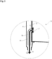
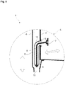
- the present invention provides a discharge line cleaning apparatus (5) readily mounted on the rear wall, i.e. the evaporator liner (2) of the storage compartment of the refrigeration appliance (1).
- said discharge line cleaning apparatus (5) in accordance with the present invention comprises a handle grip (7) for conveniently holding the discharge line cleaning apparatus (5) by reaching to the handle grip (7) at the lower part of the inner wall of the refrigeration cabin and pulling the same out from the evaporator liner (2) surface on which it is mounted.
- the handle grip (7) is integrally connected with a resilient tubular body (8) extending into a cleaning apparatus guiding housing (11) in the form of an internal cylindrical cavity.
- the cleaning apparatus guiding housing (11) has an elbow portion (12) communicating with an evaporator liner opening (6) and the remaining portion thereof extending parallel to the longitudinal axis of the water discharge line (4).
- Said tubular body (8) of the discharge line cleaning apparatus (5) is movably guided within the cleaning apparatus guiding housing (11) in a longitudinally displaceable manner.
- the handle grip (7) of the discharge line cleaning apparatus (5), normally closing the evaporator liner opening (6) can be pulled out so that the resilient tubular body (8) deforms into a longitudinal shape corresponding to the cavity formation of the cleaning apparatus guiding housing (11) and a cleaning head (9) integral with the tubular body (8) at the lowermost end thereof moves upwards to reach the lowermost end of the cleaning apparatus guiding housing (11). While being moved up and down, the cleaning head (9) crush, disperse and disintegrate the ice deposits accumulated around the discharge line outlet (10).
- the cleaning head (9) is designed as a bowl-shaped structure, having a larger top portion, normally retaining and collecting ice deposits as well as any other particles in its inactive state in the center of the flow path, while still allowing water flow down the inner walls of the discharge line (4).
- the bowl-shaped structure therefore helps in maintaining the discharge line outlet (10) open so as to allow water flow.
- the cleaning head (9) designed as a bowl-shaped structure can also be completely pulled up and removed because the head portion's largest diameter is smaller than the diameter of the tubular cleaning apparatus guiding housing (11).
- This also provides that the cleaning head (9) can also be moved in radial directions against the inner walls of the discharge line (4) as well as against the surrounding discharge line outlet (10) wall, the latter's diameter being slightly larger than that of the cleaning apparatus guiding housing (11).
- the discharge line cleaning apparatus (5) when not in use, can be stored in its inactive position until the next time it is used and can as such keep the evaporator liner opening (6) closed.
- the present invention proposes a refrigeration appliance having a cooling or refrigeration compartment for preserving foodstuff, a compressor circulating a refrigerant fluid, a condenser providing the refrigerant fluid to be condensed, an evaporator placed in an evaporator interspace (3) separated from the refrigeration compartment by means of an evaporator liner (2) and effecting refrigeration by absorbing the ambient thermal energy, a defrost system for defrosting evaporator coils and a water discharge line (4) leading from the evaporator interspace (3) to a discharge line outlet (10) so as to allow drainage of defrost water.
- a discharge line cleaning apparatus (5) is provided such that a handle grip (7) thereof being mounted on the evaporator liner (2) of the refrigeration compartment is usable in position control of a cleaning head (9) of the discharge line cleaning apparatus (5).
- the handle grip (7) is operable to be pulled out from an evaporator liner (2) surface.
- the handle grip (7) is connected with a tubular body (8) extending into a cleaning apparatus guiding housing (11) being in the form of a longitudinal cavity.
- the tubular body (8) of the discharge line cleaning apparatus (5) is movably guided within the cleaning apparatus guiding housing (11) in a longitudinally displaceable manner.
- the tubular body (8) is a resilient part deformable into a longitudinal shape dynamically corresponding to the longitudinal cavity formation of the cleaning apparatus guiding housing (11).
- the handle grip (7) is mounted in an evaporator liner opening (6) communicating with a cleaning apparatus guiding housing (11) in the form of a longitudinal cavity extending inside the evaporator interspace (3).
- the cleaning apparatus guiding housing (11) has an elbow portion (12) communicating with the evaporator liner opening (6) and extending parallel to the longitudinal axis of the water discharge line (4).
- the evaporator liner opening (6) is fully covered by the handle grip (7) of the discharge line cleaning apparatus (5).
- the cleaning head (9) extends in its inactive state beyond the level at which the discharge line outlet (10) is located in the discharge line (4).
- the cleaning head (9) is designed as a bowl-shaped structure. According to a yet still further embodiment of the present invention, the cleaning head's (9) head portion's largest diameter is smaller than the diameter of the cleaning apparatus guiding housing (11). According to a yet still further embodiment of the present invention, the cleaning head's (9) head portion's largest diameter is smaller than the diameter of the discharge line outlet (10) wall.
- the handle grip (7) is integrally formed with the tubular body (8) and the tubular body (8) is integrally formed with the cleaning head (9).
- the present invention therefore provides an advantageous and practical solution to prevent total blockage of the discharge line (4).
- the straightforward solution of the invention enables the users clean the discharge line (4) in a readily applicable manner without requiring maintenance service. Even if the deployment of repair or maintenance staff is requested, service members can effectively complete the cleaning operation in a matter of minutes.
Landscapes
- Engineering & Computer Science (AREA)
- Chemical & Material Sciences (AREA)
- Combustion & Propulsion (AREA)
- Physics & Mathematics (AREA)
- Mechanical Engineering (AREA)
- Thermal Sciences (AREA)
- General Engineering & Computer Science (AREA)
- Removal Of Water From Condensation And Defrosting (AREA)
Claims (10)
- Kältegerät mit einem Kühlfach zur Konservierung von Lebensmitteln, einem Kompressor, der ein Kältemittel zirkuliert, einem Kondensator, der das zu kondensierende Kältemittel bereitstellt, einem Verdampfer, der in einem vom Kühlfach getrennten Verdampferzwischenraum (3) mittels einer Verdampferauskleidung angeordnet ist (2) und Kälteerzeugung durch Absorption der umgebenden Wärmeenergie durchführt,Kältegerät eine Wasserablaufleitung (4) und eine Wasserablaufleitung-Reinigungsvorrichtung (5) mit einem Handgriff (7) umfasst,verwendbar in einer Positionskontrolle des Reinigungskopfes (9) der genannten Wasserablaufleitung-Reinigungvorrichtung (5) dadurch gekennzeichnet, dass- das Kältegerät ferner ein Abtausystem zum Abtauen von Verdampferschlangen und die Wasserablaufleitung (4) umfasst, die von dem Verdampferzwischenraum (3), zu einem Ablaufleitungsauslass (10) um das Abtropfen von Tauwasser zu ermöglichen führt;- Wasserablaufleitung-Reinigungsvorrichtung (5) derart vorgesehen ist, dass der Handgriff (7) derselben an der Verdampferverkleidung (2) des Kühlfaches angebracht ist,- der Handgriff (7) in einer Verdampferauskleidungsöffnung (6) angebracht ist, die mit einem Reinigungsvorrichtung-Führungsgehäuse (11) in Verbindung steht, dieser sich in einer Ablaufleitung, in Form eines länglichen Hohlraums innerhalb des Verdampferzwischenraums (3) erstreckt;- Verdampferverkleidungsöffnung (6) vollständig bedeckt durch den Handgriff (7) der Wasserablaufleitung-Reinigungsvorrichtung (5) ist;- Reinigungskopf (9) sich in seinem inaktiven Zustand über das Niveau hinaus, bei dem sich der Wasserablaufleitungauslass (10) in der Ablaufleitung (4) befindet, erstreckt.
- Kältegerät nach Anspruch 1, dadurch gekennzeichnet, dass der Handgriff (7) betriebsfähig ist, um aus einer Oberfläche einer Verdampferverkleidung (2) herausgezogen zu werden.
- Kältegerät nach Anspruch 1 oder 2, dadurch gekennzeichnet, dass der Handgriff (7) verbunden mit einem rohrförmigen Körper (8), der sich in das Reinigungsvorrichtung-Führungsgehäuse (11), das in Form eines längsläufigen Hohlraums ausgebildet ist, erstreckt.
- Kältegerät nach Anspruch 3, dadurch gekennzeichnet, dass der rohrförmige Körper (8) der Wasserablaufleitung- Reinigungsvorrichtung (5) innerhalb des Reinigungsvorrichtung-Führungsgehäuses (11) längsverschiebbar geführt ist.
- Kältegerät nach Anspruch 3 oder 4, dadurch gekennzeichnet, dass der rohgörmige Körper (8) ein Federteil ist, das zu einer länglichen Form verformbar ist, die der längsläufige Hohlraumbildung des Reinigungsvorrichtung-Führungsgehäuses (11) dynamisch entspricht.
- Kältegerät nach einem der Ansprüche 1 bis 5, dadurch gekennzeichnet, dass das Reinigungsvorrichtung-Führungsgehäuse (11) einen Krümmungsabschnitt (12) aufweist, der mit einer Verdampferverkleidungsöffnung (6) in Verbindung steht.
- Kältegerät nach einem der Ansprüche 1 bis 6, dadurch gekennzeichnet, dass das Reinigungskopf (9) als eine schalenförmige Struktur ausgebildet ist.
- Kältegerät nach Anspruch 7, dadurch gekennzeichnet, dass der größte Durchmesser des Kopfteils des Reinigungskopfes (9) kleiner als der Durchmesser des Reinigungsvorrichtung-Führungsgehäuses (11) ist.
- Kältegerät nach Anspruch 7 oder 8, dadurch gekennzeichnet, dass der größte Durchmesser des Kopfteils des Reinigungskopfes (9) kleiner als der Durchmesser der Wand des Wasserablaufleitungauslasses (10) ist.
- Kältegerät nach einem der Ansprüche 3 bis 5, dadurch gekennzeichnet, dass das Handgriff (7) einstückig mit dem rohrförmigen Köper (8) ausgebildet ist und der rohrförmige Körper (8) einstückig mit dem Reinigungskopf (9) ausgebildet ist.
Applications Claiming Priority (1)
| Application Number | Priority Date | Filing Date | Title |
|---|---|---|---|
| PCT/EP2014/058816 WO2015165519A1 (en) | 2014-04-30 | 2014-04-30 | Refrigeration appliance having a defrost water drainage line anti-blockage mechanism |
Publications (2)
| Publication Number | Publication Date |
|---|---|
| EP3137822A1 EP3137822A1 (de) | 2017-03-08 |
| EP3137822B1 true EP3137822B1 (de) | 2018-07-11 |
Family
ID=50628821
Family Applications (1)
| Application Number | Title | Priority Date | Filing Date |
|---|---|---|---|
| EP14720603.1A Active EP3137822B1 (de) | 2014-04-30 | 2014-04-30 | Kühlvorrichtung mit entblockiermechanismus für abtauwasserableitung |
Country Status (2)
| Country | Link |
|---|---|
| EP (1) | EP3137822B1 (de) |
| WO (1) | WO2015165519A1 (de) |
Families Citing this family (1)
| Publication number | Priority date | Publication date | Assignee | Title |
|---|---|---|---|---|
| CN114811011B (zh) * | 2022-04-24 | 2025-06-27 | 安徽马钢和菱实业有限公司 | 一种减速机油位油温显示装置的油管清洁方法 |
Citations (1)
| Publication number | Priority date | Publication date | Assignee | Title |
|---|---|---|---|---|
| CN203719296U (zh) * | 2014-01-08 | 2014-07-16 | 合肥美的电冰箱有限公司 | 冰箱和用于冰箱的排水管清洁塞 |
Family Cites Families (4)
| Publication number | Priority date | Publication date | Assignee | Title |
|---|---|---|---|---|
| US1824924A (en) * | 1931-05-25 | 1931-09-29 | Paul Edwin | Guide for pipe cleaning rods |
| US4179762A (en) * | 1978-08-24 | 1979-12-25 | Barnhardt Kenneth O | Trap and solids removal assembly for drains |
| US5069042A (en) * | 1990-04-13 | 1991-12-03 | Stuchlik Iii Charles F | Cleanable condensate trap |
| DE102009026667A1 (de) * | 2009-06-03 | 2010-12-09 | BSH Bosch und Siemens Hausgeräte GmbH | Kältegerät mit druckausgleichendem Durchgang |
-
2014
- 2014-04-30 WO PCT/EP2014/058816 patent/WO2015165519A1/en not_active Ceased
- 2014-04-30 EP EP14720603.1A patent/EP3137822B1/de active Active
Patent Citations (1)
| Publication number | Priority date | Publication date | Assignee | Title |
|---|---|---|---|---|
| CN203719296U (zh) * | 2014-01-08 | 2014-07-16 | 合肥美的电冰箱有限公司 | 冰箱和用于冰箱的排水管清洁塞 |
Also Published As
| Publication number | Publication date |
|---|---|
| WO2015165519A1 (en) | 2015-11-05 |
| EP3137822A1 (de) | 2017-03-08 |
Similar Documents
| Publication | Publication Date | Title |
|---|---|---|
| US20100031675A1 (en) | Ice making system and method for ice making of refrigerator | |
| US20140209125A1 (en) | Ice maker with slide out sump | |
| CN102829598B (zh) | 一种冰箱自动除霜系统及控制方法 | |
| US8453475B2 (en) | System and method for making ice | |
| KR20100085228A (ko) | 냉장고의 제상 장치 | |
| EP3106798B1 (de) | Eisherstellungssystem und -verfahren für einen kühlschrank | |
| EP3137822B1 (de) | Kühlvorrichtung mit entblockiermechanismus für abtauwasserableitung | |
| US10180273B2 (en) | Ice making system and method for a refrigerator | |
| US20140196493A1 (en) | Refrigerator appliance | |
| KR20180006570A (ko) | 증발기 유닛 및 이를 구비한 냉장고 | |
| KR101698101B1 (ko) | 냉장고 및 이의 제어방법 | |
| CN207317353U (zh) | 直接送风卧式无霜冷柜 | |
| WO2015165512A1 (en) | Refrigeration appliance having an anti-condensation arrangement | |
| KR20130008990A (ko) | 냉장고 제상장치 | |
| WO2015185090A1 (en) | Refrigeration appliance compressor having an integrated water collection receptacle | |
| US10488102B2 (en) | Household cooling appliance with an ice tray and a cooling device in a door | |
| JP2011141061A (ja) | 飲料用缶、飲料用瓶及びペットボトル用急速冷却室を備えた家庭用冷凍冷蔵庫 | |
| EP3034971A1 (de) | Kühlvorrichtung, insbesondere für den haushaltsgebrauch, und zugehöriges verfahren zur herstellung | |
| WO2016034223A1 (en) | Refrigeration appliance compressor variable volume water collection receptacle | |
| CN106225372B (zh) | 直冷式冰箱 | |
| KR20080074434A (ko) | 냉장고 | |
| KR20100085237A (ko) | 바스켓 및 이를 구비하는 냉장고 | |
| US20160231044A1 (en) | Refrigerator having circulation guiding structure enabling an improved thermal distribution profile | |
| KR101328770B1 (ko) | 냉장고의 재열제습 시스템 | |
| WO2012089454A2 (en) | A cooling device comprising a collection container |
Legal Events
| Date | Code | Title | Description |
|---|---|---|---|
| PUAI | Public reference made under article 153(3) epc to a published international application that has entered the european phase |
Free format text: ORIGINAL CODE: 0009012 |
|
| STAA | Information on the status of an ep patent application or granted ep patent |
Free format text: STATUS: REQUEST FOR EXAMINATION WAS MADE |
|
| 17P | Request for examination filed |
Effective date: 20160729 |
|
| AK | Designated contracting states |
Kind code of ref document: A1 Designated state(s): AL AT BE BG CH CY CZ DE DK EE ES FI FR GB GR HR HU IE IS IT LI LT LU LV MC MK MT NL NO PL PT RO RS SE SI SK SM TR |
|
| AX | Request for extension of the european patent |
Extension state: BA ME |
|
| DAX | Request for extension of the european patent (deleted) | ||
| GRAP | Despatch of communication of intention to grant a patent |
Free format text: ORIGINAL CODE: EPIDOSNIGR1 |
|
| STAA | Information on the status of an ep patent application or granted ep patent |
Free format text: STATUS: GRANT OF PATENT IS INTENDED |
|
| INTG | Intention to grant announced |
Effective date: 20180319 |
|
| GRAS | Grant fee paid |
Free format text: ORIGINAL CODE: EPIDOSNIGR3 |
|
| GRAA | (expected) grant |
Free format text: ORIGINAL CODE: 0009210 |
|
| STAA | Information on the status of an ep patent application or granted ep patent |
Free format text: STATUS: THE PATENT HAS BEEN GRANTED |
|
| AK | Designated contracting states |
Kind code of ref document: B1 Designated state(s): AL AT BE BG CH CY CZ DE DK EE ES FI FR GB GR HR HU IE IS IT LI LT LU LV MC MK MT NL NO PL PT RO RS SE SI SK SM TR |
|
| REG | Reference to a national code |
Ref country code: GB Ref legal event code: FG4D |
|
| REG | Reference to a national code |
Ref country code: CH Ref legal event code: EP |
|
| REG | Reference to a national code |
Ref country code: AT Ref legal event code: REF Ref document number: 1017299 Country of ref document: AT Kind code of ref document: T Effective date: 20180715 |
|
| REG | Reference to a national code |
Ref country code: DE Ref legal event code: R096 Ref document number: 602014028256 Country of ref document: DE |
|
| REG | Reference to a national code |
Ref country code: IE Ref legal event code: FG4D |
|
| REG | Reference to a national code |
Ref country code: NL Ref legal event code: MP Effective date: 20180711 |
|
| REG | Reference to a national code |
Ref country code: LT Ref legal event code: MG4D |
|
| REG | Reference to a national code |
Ref country code: AT Ref legal event code: MK05 Ref document number: 1017299 Country of ref document: AT Kind code of ref document: T Effective date: 20180711 |
|
| PG25 | Lapsed in a contracting state [announced via postgrant information from national office to epo] |
Ref country code: NL Free format text: LAPSE BECAUSE OF FAILURE TO SUBMIT A TRANSLATION OF THE DESCRIPTION OR TO PAY THE FEE WITHIN THE PRESCRIBED TIME-LIMIT Effective date: 20180711 |
|
| PG25 | Lapsed in a contracting state [announced via postgrant information from national office to epo] |
Ref country code: GR Free format text: LAPSE BECAUSE OF FAILURE TO SUBMIT A TRANSLATION OF THE DESCRIPTION OR TO PAY THE FEE WITHIN THE PRESCRIBED TIME-LIMIT Effective date: 20181012 Ref country code: NO Free format text: LAPSE BECAUSE OF FAILURE TO SUBMIT A TRANSLATION OF THE DESCRIPTION OR TO PAY THE FEE WITHIN THE PRESCRIBED TIME-LIMIT Effective date: 20181011 Ref country code: AT Free format text: LAPSE BECAUSE OF FAILURE TO SUBMIT A TRANSLATION OF THE DESCRIPTION OR TO PAY THE FEE WITHIN THE PRESCRIBED TIME-LIMIT Effective date: 20180711 Ref country code: BG Free format text: LAPSE BECAUSE OF FAILURE TO SUBMIT A TRANSLATION OF THE DESCRIPTION OR TO PAY THE FEE WITHIN THE PRESCRIBED TIME-LIMIT Effective date: 20181011 Ref country code: FI Free format text: LAPSE BECAUSE OF FAILURE TO SUBMIT A TRANSLATION OF THE DESCRIPTION OR TO PAY THE FEE WITHIN THE PRESCRIBED TIME-LIMIT Effective date: 20180711 Ref country code: PL Free format text: LAPSE BECAUSE OF FAILURE TO SUBMIT A TRANSLATION OF THE DESCRIPTION OR TO PAY THE FEE WITHIN THE PRESCRIBED TIME-LIMIT Effective date: 20180711 Ref country code: LT Free format text: LAPSE BECAUSE OF FAILURE TO SUBMIT A TRANSLATION OF THE DESCRIPTION OR TO PAY THE FEE WITHIN THE PRESCRIBED TIME-LIMIT Effective date: 20180711 Ref country code: IS Free format text: LAPSE BECAUSE OF FAILURE TO SUBMIT A TRANSLATION OF THE DESCRIPTION OR TO PAY THE FEE WITHIN THE PRESCRIBED TIME-LIMIT Effective date: 20181111 Ref country code: RS Free format text: LAPSE BECAUSE OF FAILURE TO SUBMIT A TRANSLATION OF THE DESCRIPTION OR TO PAY THE FEE WITHIN THE PRESCRIBED TIME-LIMIT Effective date: 20180711 Ref country code: SE Free format text: LAPSE BECAUSE OF FAILURE TO SUBMIT A TRANSLATION OF THE DESCRIPTION OR TO PAY THE FEE WITHIN THE PRESCRIBED TIME-LIMIT Effective date: 20180711 |
|
| PG25 | Lapsed in a contracting state [announced via postgrant information from national office to epo] |
Ref country code: AL Free format text: LAPSE BECAUSE OF FAILURE TO SUBMIT A TRANSLATION OF THE DESCRIPTION OR TO PAY THE FEE WITHIN THE PRESCRIBED TIME-LIMIT Effective date: 20180711 Ref country code: LV Free format text: LAPSE BECAUSE OF FAILURE TO SUBMIT A TRANSLATION OF THE DESCRIPTION OR TO PAY THE FEE WITHIN THE PRESCRIBED TIME-LIMIT Effective date: 20180711 Ref country code: HR Free format text: LAPSE BECAUSE OF FAILURE TO SUBMIT A TRANSLATION OF THE DESCRIPTION OR TO PAY THE FEE WITHIN THE PRESCRIBED TIME-LIMIT Effective date: 20180711 |
|
| REG | Reference to a national code |
Ref country code: DE Ref legal event code: R097 Ref document number: 602014028256 Country of ref document: DE |
|
| PG25 | Lapsed in a contracting state [announced via postgrant information from national office to epo] |
Ref country code: EE Free format text: LAPSE BECAUSE OF FAILURE TO SUBMIT A TRANSLATION OF THE DESCRIPTION OR TO PAY THE FEE WITHIN THE PRESCRIBED TIME-LIMIT Effective date: 20180711 Ref country code: IT Free format text: LAPSE BECAUSE OF FAILURE TO SUBMIT A TRANSLATION OF THE DESCRIPTION OR TO PAY THE FEE WITHIN THE PRESCRIBED TIME-LIMIT Effective date: 20180711 Ref country code: ES Free format text: LAPSE BECAUSE OF FAILURE TO SUBMIT A TRANSLATION OF THE DESCRIPTION OR TO PAY THE FEE WITHIN THE PRESCRIBED TIME-LIMIT Effective date: 20180711 Ref country code: RO Free format text: LAPSE BECAUSE OF FAILURE TO SUBMIT A TRANSLATION OF THE DESCRIPTION OR TO PAY THE FEE WITHIN THE PRESCRIBED TIME-LIMIT Effective date: 20180711 Ref country code: CZ Free format text: LAPSE BECAUSE OF FAILURE TO SUBMIT A TRANSLATION OF THE DESCRIPTION OR TO PAY THE FEE WITHIN THE PRESCRIBED TIME-LIMIT Effective date: 20180711 |
|
| PLBE | No opposition filed within time limit |
Free format text: ORIGINAL CODE: 0009261 |
|
| STAA | Information on the status of an ep patent application or granted ep patent |
Free format text: STATUS: NO OPPOSITION FILED WITHIN TIME LIMIT |
|
| PG25 | Lapsed in a contracting state [announced via postgrant information from national office to epo] |
Ref country code: SK Free format text: LAPSE BECAUSE OF FAILURE TO SUBMIT A TRANSLATION OF THE DESCRIPTION OR TO PAY THE FEE WITHIN THE PRESCRIBED TIME-LIMIT Effective date: 20180711 Ref country code: SM Free format text: LAPSE BECAUSE OF FAILURE TO SUBMIT A TRANSLATION OF THE DESCRIPTION OR TO PAY THE FEE WITHIN THE PRESCRIBED TIME-LIMIT Effective date: 20180711 Ref country code: DK Free format text: LAPSE BECAUSE OF FAILURE TO SUBMIT A TRANSLATION OF THE DESCRIPTION OR TO PAY THE FEE WITHIN THE PRESCRIBED TIME-LIMIT Effective date: 20180711 |
|
| 26N | No opposition filed |
Effective date: 20190412 |
|
| PG25 | Lapsed in a contracting state [announced via postgrant information from national office to epo] |
Ref country code: SI Free format text: LAPSE BECAUSE OF FAILURE TO SUBMIT A TRANSLATION OF THE DESCRIPTION OR TO PAY THE FEE WITHIN THE PRESCRIBED TIME-LIMIT Effective date: 20180711 |
|
| REG | Reference to a national code |
Ref country code: CH Ref legal event code: PL |
|
| REG | Reference to a national code |
Ref country code: BE Ref legal event code: MM Effective date: 20190430 |
|
| GBPC | Gb: european patent ceased through non-payment of renewal fee |
Effective date: 20190430 |
|
| PG25 | Lapsed in a contracting state [announced via postgrant information from national office to epo] |
Ref country code: MC Free format text: LAPSE BECAUSE OF FAILURE TO SUBMIT A TRANSLATION OF THE DESCRIPTION OR TO PAY THE FEE WITHIN THE PRESCRIBED TIME-LIMIT Effective date: 20180711 Ref country code: LU Free format text: LAPSE BECAUSE OF NON-PAYMENT OF DUE FEES Effective date: 20190430 |
|
| PG25 | Lapsed in a contracting state [announced via postgrant information from national office to epo] |
Ref country code: GB Free format text: LAPSE BECAUSE OF NON-PAYMENT OF DUE FEES Effective date: 20190430 Ref country code: CH Free format text: LAPSE BECAUSE OF NON-PAYMENT OF DUE FEES Effective date: 20190430 Ref country code: LI Free format text: LAPSE BECAUSE OF NON-PAYMENT OF DUE FEES Effective date: 20190430 |
|
| PG25 | Lapsed in a contracting state [announced via postgrant information from national office to epo] |
Ref country code: FR Free format text: LAPSE BECAUSE OF NON-PAYMENT OF DUE FEES Effective date: 20190430 Ref country code: BE Free format text: LAPSE BECAUSE OF NON-PAYMENT OF DUE FEES Effective date: 20190430 |
|
| PG25 | Lapsed in a contracting state [announced via postgrant information from national office to epo] |
Ref country code: IE Free format text: LAPSE BECAUSE OF NON-PAYMENT OF DUE FEES Effective date: 20190430 |
|
| PG25 | Lapsed in a contracting state [announced via postgrant information from national office to epo] |
Ref country code: PT Free format text: LAPSE BECAUSE OF FAILURE TO SUBMIT A TRANSLATION OF THE DESCRIPTION OR TO PAY THE FEE WITHIN THE PRESCRIBED TIME-LIMIT Effective date: 20181111 |
|
| PG25 | Lapsed in a contracting state [announced via postgrant information from national office to epo] |
Ref country code: CY Free format text: LAPSE BECAUSE OF FAILURE TO SUBMIT A TRANSLATION OF THE DESCRIPTION OR TO PAY THE FEE WITHIN THE PRESCRIBED TIME-LIMIT Effective date: 20180711 |
|
| PG25 | Lapsed in a contracting state [announced via postgrant information from national office to epo] |
Ref country code: MT Free format text: LAPSE BECAUSE OF FAILURE TO SUBMIT A TRANSLATION OF THE DESCRIPTION OR TO PAY THE FEE WITHIN THE PRESCRIBED TIME-LIMIT Effective date: 20180711 Ref country code: HU Free format text: LAPSE BECAUSE OF FAILURE TO SUBMIT A TRANSLATION OF THE DESCRIPTION OR TO PAY THE FEE WITHIN THE PRESCRIBED TIME-LIMIT; INVALID AB INITIO Effective date: 20140430 |
|
| PG25 | Lapsed in a contracting state [announced via postgrant information from national office to epo] |
Ref country code: MK Free format text: LAPSE BECAUSE OF FAILURE TO SUBMIT A TRANSLATION OF THE DESCRIPTION OR TO PAY THE FEE WITHIN THE PRESCRIBED TIME-LIMIT Effective date: 20180711 |
|
| PGFP | Annual fee paid to national office [announced via postgrant information from national office to epo] |
Ref country code: DE Payment date: 20250422 Year of fee payment: 12 |
|
| PGFP | Annual fee paid to national office [announced via postgrant information from national office to epo] |
Ref country code: TR Payment date: 20250414 Year of fee payment: 12 |