EP3137777B1 - System comprising an externally threaded bolt - Google Patents
System comprising an externally threaded bolt Download PDFInfo
- Publication number
- EP3137777B1 EP3137777B1 EP15720557.6A EP15720557A EP3137777B1 EP 3137777 B1 EP3137777 B1 EP 3137777B1 EP 15720557 A EP15720557 A EP 15720557A EP 3137777 B1 EP3137777 B1 EP 3137777B1
- Authority
- EP
- European Patent Office
- Prior art keywords
- thread
- bolt
- threads
- nut
- entry point
- Prior art date
- Legal status (The legal status is an assumption and is not a legal conclusion. Google has not performed a legal analysis and makes no representation as to the accuracy of the status listed.)
- Active
Links
- 239000011295 pitch Substances 0.000 description 20
- 230000002411 adverse Effects 0.000 description 5
- 230000013011 mating Effects 0.000 description 3
- 238000013459 approach Methods 0.000 description 2
- 230000008901 benefit Effects 0.000 description 2
- 238000010586 diagram Methods 0.000 description 2
- 238000000034 method Methods 0.000 description 2
- 238000010276 construction Methods 0.000 description 1
- 230000001419 dependent effect Effects 0.000 description 1
- 230000000694 effects Effects 0.000 description 1
- 238000003780 insertion Methods 0.000 description 1
- 230000037431 insertion Effects 0.000 description 1
- 230000008520 organization Effects 0.000 description 1
Images


Classifications
-
- F—MECHANICAL ENGINEERING; LIGHTING; HEATING; WEAPONS; BLASTING
- F16—ENGINEERING ELEMENTS AND UNITS; GENERAL MEASURES FOR PRODUCING AND MAINTAINING EFFECTIVE FUNCTIONING OF MACHINES OR INSTALLATIONS; THERMAL INSULATION IN GENERAL
- F16B—DEVICES FOR FASTENING OR SECURING CONSTRUCTIONAL ELEMENTS OR MACHINE PARTS TOGETHER, e.g. NAILS, BOLTS, CIRCLIPS, CLAMPS, CLIPS OR WEDGES; JOINTS OR JOINTING
- F16B33/00—Features common to bolt and nut
- F16B33/02—Shape of thread; Special thread-forms
-
- F—MECHANICAL ENGINEERING; LIGHTING; HEATING; WEAPONS; BLASTING
- F16—ENGINEERING ELEMENTS AND UNITS; GENERAL MEASURES FOR PRODUCING AND MAINTAINING EFFECTIVE FUNCTIONING OF MACHINES OR INSTALLATIONS; THERMAL INSULATION IN GENERAL
- F16B—DEVICES FOR FASTENING OR SECURING CONSTRUCTIONAL ELEMENTS OR MACHINE PARTS TOGETHER, e.g. NAILS, BOLTS, CIRCLIPS, CLAMPS, CLIPS OR WEDGES; JOINTS OR JOINTING
- F16B35/00—Screw-bolts; Stay-bolts; Screw-threaded studs; Screws; Set screws
- F16B35/04—Screw-bolts; Stay-bolts; Screw-threaded studs; Screws; Set screws with specially-shaped head or shaft in order to fix the bolt on or in an object
- F16B35/041—Specially-shaped shafts
- F16B35/044—Specially-shaped ends
- F16B35/047—Specially-shaped ends for preventing cross-threading, i.e. preventing skewing of bolt and nut
Description
- This application claims benefit of
U.S. Provisional Application No. 61/987,138, filed on May 1, 2015 - In general and with reference to
Fig. 1 it is recognized that an assembly that requires abolt thread 1, of standard proportions, to be inserted into apre-threaded nut 2, of standard proportions, can often result in a condition where the crest of thebolt thread - As will be appreciated by those skilled in the art, cross threading becomes more prevalent where the axes of the
bolt thread 4 and thenut thread 5 are out of angular alignment at the initial point of assembly. It requires only a small misalignment ofaxes - Many attempts have been introduced to bolt lead entry threads and/or nut entry threads, to overcome this adverse assembly condition. Exemplary anti-cross threading devices are described in
United States Patent Nos. 7,334,975, entitled FASTENER ASSEMBLY, by Jungman, et al ,7,438,512, entitled U-BOLT ASSEMBLY, by Jakuszeski, et al. and5,836,731, entitled ANTI-CROSS THREADED FASTENER, by Goodwin et al. - An example of the systems in current use can be viewed in relation to
Fig. 2 . Conventional systems rely upon changes to the bolt lead entry pointgeometrical configuration 14 that is aimed toward encouraging the lead threads of the bolt to slide over the nut thread root diameter and to assist in the mating threads creating thread pitch engagement and minimize cross threading. The above noted prior art recognizes that the circular (or radius) cross section of thelead entry threads 14 may not achieve this aim and anticipate that an additional plain dog point of circular cross section or of a special form that diminishes in magnitude as the section approaches the bolt entry end may be a requirement toward resisting nut and bolt threads from cross threading. - In each of these cases, the
axial pitch 12 of the bolt lead entry threads are maintained at the same numerical value as the standard pitch of the bolt and nut threads. Without the extended point feature and with a small amount of misalignment between the nut and bolt axes, it remains a possibility for the initial assembly conditions as outlined and discussed in relation toFig. 1 to be present and, due to the influence of theconstant thread pitch 12, cross threading will still occur. -
EP 2 163 773 - In
EP 1 296 070 A2 - The present inventions relates to a fastener system according to
claim 1. Preferred embodiments are part of the the dependent claims. - The organization and method of the invention together with further objects and advantages thereof can best be understood with reference to the following descriptions and accompanying drawings in which like reference numerals identify identical or functionally identical elements and in which:
-
Fig. 1 , previously described, is a schematic diagram illustrating the conditions that take place and can that lead to the adverse assembly condition of cross threading; -
Fig. 2 , previously described, is a schematic diagram illustrating a prior art method aimed toward overcoming cross threading; -
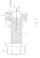
Fig. 3 is a schematic illustration of a bolt in accordance with an illustrative embodiment of the present invention; and -
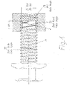
Fig. 4 an illustration of the effect that the variable pitch lead threads have in developing axial alignment of the nut and bolt threads in accordance with an illustrative embodiment of the present invention. - The present disclosure should be considered as an exemplification of the principles of illustrative embodiments of the present invention and that it is not intended to limit the invention to those embodiments illustrated and described herein. The system and principles may be susceptible to embodiments in differing forms from those that are described in detail.
- Referring again to
Fig. 1 , there is shown a schematic illustration of a fastener system comprising a bolt in accordance with the present invention and a pre-threaded nut into which the bolt is to be assembled. It should be noted that while the description is written in terms of a bolt, any externally threaded fastener may be utilized in accordance with alternative embodiments of the present invention. It should further be noted that the description term 'nut' can be related to any internally threaded fastener that may be utilized in accordance with alternative embodiments of the present invention. As such, the description of a bolt and a nut as being utilized should be viewed as exemplary only. - The bolt and nut are being operatively assembled and whereby the
bolt thread crest 10 contacts thenut thread root 11 and creates a potential thread interference, in these contact zones, where the bolt is rotated in a clockwise direction, relative to the nut, when viewed from the bolt head end of the assembly (denoted by arrow X) and due to the thread helix angles of the bolt and nut threads generated from theaxial pitch 12 andmajor diameter 30 of the chosen thread, the bolt wants to move axially forward relative to the nut. However, due to the helix angles of both the nut thread and the bolt thread being of the same magnitude, the crest of the bolt thread maintains its initial contact position with the root of the nut thread and creates an increasing interference in the contact zones. This increasing interference will cause the relative bolt and nut threads to seize or otherwise jam. - Referring again to
Fig. 2 , there is illustrated a proprietary system that has been developed to overcome this initial adverse assembly condition. The system, as illustrated, relates to a number of different patents, described and previously incorporated by reference above. The system illustratively has a bolt threadentry point pitch 12 that is of the same magnitude as the nut andbolt pitches 12. However, a noted disadvantage of such a system is that should the initial thread contact be that of allowing thebolt thread crest 10 to contact thenut thread root 11, a similar adverse assembly condition, to that previously outlined, can develop, i.e., the bolt and the nut may become cross threaded. - Referring to
Fig. 3 of the drawings there is shown a schematic illustration of the bolt in accordance with an illustrative embodiment of the present invention that comprises ahead 20, a shank (or body)portion 21 and alead entry point 22. Thehead 20 can be of any configuration that may be used for developing rotational movement to the bolt by means of a fastener drive system. Theshank portion 21 may be round or may have a lobular cross sectional area as is known to those skilled in the art. - The
shank 21 illustratively has athread 25 formed thereon. Thethread 25 is illustratively generated as a helical form around acore 26 in a manner that contains athread height 27 as being of a constant magnitude for a specified size of bolt. The helical thread generated is illustratively in accordance with a known international/national standards specification or may be in accordance with a proprietary threaded fastener system that may deviate from international and/or national standards specifications. The thread on theshank 21 illustratively has anaxial pitch 12 that develops thethread helix angle 28 in relationship to theaxial pitch 12 and the bolt thread outsidediameter 30. Thebolt thread 25 may extend over the length of the bolt shank or may extend over only a portion thereof. - In accordance with an illustrative embodiment of the present invention, the
bolt thread pitch 12 is the same as the pitch of the pre-threaded nut that has been chosen by the assembly fabricator. - The bolt lead entry threads are illustratively of an
outside diameter 31 that nominally equates to the nutthread root diameter 36. Thethread diameter 31 is nominally parallel in illustrative embodiments of the present invention. It is recognized that for practical purposes, the outside circumscribing circle of thelead threads 31 will be reduced below the inner diameter of thenut threads 36 such that the boltlead entry threads 22 can enter thenut threads 2 without designed interference being present. - The lead entry point threads have a
thread pitch 39 that equates to approximately 1.562 times the threadaxial pitch 12 of the body threads of the bolt in accordance with an illustrative embodiment of the present invention. More generally, the lead entrypoint thread pitch 39 may be within the range of approximately 1.40 to 1.60 times the body threadaxial pitch 12. - Referring to
Fig. 4 it will be seen that thelead entry threads 22 of the bolt do not engage thethread profile 2 of the nut. They do make contact with the root diameter of thenut thread 36 and due to theirhigher pitch 39 andsubsequent helix angle 38, when related to thenut helix angle 28, will accelerate the bolt axial movement relative to the nut thread than would be the case if all threads were of the same pitch. - When the accelerated forward movement takes place there is created axial alignment of the nut and bolt axes such that the
main body threads 25 approach and contact thenut thread cavities 2 in a way that will eliminate the high potential for cross threading that has been encountered with previously designed (prior art) systems. - The geometrical construction of the bolt angle of the lead entry threads and the manner, in which the body threads and the lead entry threads are interrelated, work to ensure that the
thread helix angle 38 of the lead entry threads is greater than thethread helix angle 28 of the body threads. As can be seen inFig. 4 , should the insertion of the bolt be at an angle that does not line up with the axis of the nut thread and should the crest of the lead angle threads contact the root of the nut thread, the higher helix angle of the bolt thread lead will accelerate the bolt threads forward at a rate that is faster than would normally be achieved should the helix angles match. This action will tend toward pulling the axes of the related threaded parts into alignment. - It can be further seen that the action of increasing the forward movement of the lead entry threads relative to the nut threads will eliminate the potential for the bolt thread crest to produce interference with the nut thread root and eliminate the potential for cross threading, in the manner prescribed in the references to
Fig. 1 . - The main body threads will, under these conditions, achieve initial mating thread contact in an acceptable and prescribed manner and will eliminate the cross threading that has been seen as cause for concern.
Claims (4)
- A system comprising:a shank (21) of a bolt, having an external thread (25) suitable to engage a pre-threaded internal thread (12) in anut member, wherein the external thread (25) of the shank and the internal thread of the nut member have a same thread pitch (12) and a same thread helix angle (28);a lead entry point on the bolt, having threads (22) with an entry point thread pitch (39) higher in magnitude than the thread pitch (12) of the shank, wherein the threads of the lead entry point (22) have an entry point helix angle (38) higher in magnitude than the thread helix angle (28), of the shank of the bolt,wherein the lead entry point threads are v-shaped, and
wherein an outside diameter (31) of the threads of the lead entry point (22) is smaller than that of the minor diameter (36) of the nut member to allow for a sliding fit to be present without any interference patterns to occur at these diameters. - The system of claim 1 wherein the entry point thread pitch (39) equals approximately 1.562 times the thread pitch.
- The system of claim 1 wherein the entry point thread pitch lies within the range of 1.4 to 1.6 times greater than the pitch of the threads of the shank.
- The system in accordance with claim 1 wherein a thread root diameter of the threads along the lead entry point is equal to or less than that of a thread root diameter of threads along the shank.
Applications Claiming Priority (2)
| Application Number | Priority Date | Filing Date | Title |
|---|---|---|---|
| US201461987138P | 2014-05-01 | 2014-05-01 | |
| PCT/US2015/027788 WO2015168017A1 (en) | 2014-05-01 | 2015-04-27 | Fastener system comprising an externally threaded bolt and an internally threaded nut for the avoidance of cross-threading of the mating threads during assembly |
Publications (2)
| Publication Number | Publication Date |
|---|---|
| EP3137777A1 EP3137777A1 (en) | 2017-03-08 |
| EP3137777B1 true EP3137777B1 (en) | 2022-06-08 |
Family
ID=53051959
Family Applications (1)
| Application Number | Title | Priority Date | Filing Date |
|---|---|---|---|
| EP15720557.6A Active EP3137777B1 (en) | 2014-05-01 | 2015-04-27 | System comprising an externally threaded bolt |
Country Status (16)
| Country | Link |
|---|---|
| US (2) | US9835193B2 (en) |
| EP (1) | EP3137777B1 (en) |
| JP (1) | JP6482091B2 (en) |
| KR (1) | KR102159855B1 (en) |
| CN (1) | CN106471265A (en) |
| AU (1) | AU2015253420B2 (en) |
| BR (1) | BR112016021101B1 (en) |
| CA (1) | CA2939140C (en) |
| ES (1) | ES2920799T3 (en) |
| MX (1) | MX2016010624A (en) |
| MY (1) | MY188117A (en) |
| PL (1) | PL3137777T3 (en) |
| RU (2) | RU2677409C2 (en) |
| SG (1) | SG11201606809YA (en) |
| TW (1) | TWI680236B (en) |
| WO (1) | WO2015168017A1 (en) |
Families Citing this family (7)
| Publication number | Priority date | Publication date | Assignee | Title |
|---|---|---|---|---|
| USD818356S1 (en) * | 2017-01-04 | 2018-05-22 | Shamrock International Fastener Llc | Bolt |
| USD825322S1 (en) * | 2017-01-04 | 2018-08-14 | Shamrock International Fastener Llc | Nut for bolt |
| IT201700077422A1 (en) * | 2017-07-10 | 2019-01-10 | Mr Ind Fasteners S R L | THREADED PIN |
| JP6980970B2 (en) * | 2018-01-26 | 2021-12-15 | メイラ株式会社 | Bone treatment tools, bone screws and bone plates |
| JP6434668B1 (en) * | 2018-06-13 | 2018-12-05 | 株式会社トープラ | Male thread member |
| US10927877B2 (en) | 2019-01-11 | 2021-02-23 | Mathread, Inc. | Shortened fastener with locally controlled thread height |
| CN110645250B (en) * | 2019-09-30 | 2021-03-02 | 宁波金鼎紧固件有限公司 | Big flange face extrusion self sealss check bolt of hexagonal |
Family Cites Families (19)
| Publication number | Priority date | Publication date | Assignee | Title |
|---|---|---|---|---|
| JPS51131558U (en) * | 1975-04-14 | 1976-10-23 | ||
| US4040328A (en) * | 1976-03-10 | 1977-08-09 | Research Engineering & Manufacturing, Inc. | Thread-forming fastener having dual lobulation and dies for making the same |
| US4844676A (en) | 1986-10-23 | 1989-07-04 | Pheoll Manufacturing Company, Inc. | Self-penetrating screw |
| US5836731A (en) | 1987-05-20 | 1998-11-17 | Mathread, Inc. | Anti-cross threading fastener |
| JP2500997B2 (en) * | 1993-06-30 | 1996-05-29 | 勝美 池田 | How to connect screw bodies |
| JP3469846B2 (en) * | 1999-07-13 | 2003-11-25 | 株式会社メイドー | Guide boss grooved bolt |
| JP2002081426A (en) * | 1999-12-15 | 2002-03-22 | Meidoo:Kk | Bolt with guiding boss portion and manufacturing method therefor |
| US6561741B2 (en) * | 2000-12-19 | 2003-05-13 | Michael A. Garver | Fastener with aligning lead thread |
| US7334975B2 (en) | 2001-08-20 | 2008-02-26 | Maclean-Fogg Company | Fastener assembly |
| US7438512B2 (en) | 2001-08-20 | 2008-10-21 | Maclean-Fogg Company | U-bolt assembly |
| JP4171631B2 (en) | 2001-09-25 | 2008-10-22 | 株式会社青山製作所 | bolt |
| JP2003184848A (en) * | 2001-12-19 | 2003-07-03 | Eco World:Kk | Locking bolt |
| JP2004036733A (en) * | 2002-07-02 | 2004-02-05 | Nitto Seiko Co Ltd | Female screw formation waste absorbing screw |
| RU2361125C1 (en) * | 2005-06-13 | 2009-07-10 | Аояма Сейсакусо Ко., Лтд. | Bolt |
| US7866930B2 (en) * | 2005-06-13 | 2011-01-11 | Aoyama Seisakusho Co., Ltd. | Bolt |
| DE102008042141A1 (en) | 2008-09-16 | 2010-03-25 | Kamax-Werke Rudolf Kellermann Gmbh & Co. Kg | Self-centering screw |
| EP2334938B1 (en) * | 2008-10-02 | 2013-05-01 | Aoyama Seisakusho Co., Ltd. | Anti cross-thread bolt |
| CN201306348Y (en) * | 2009-03-03 | 2009-09-09 | 安徽天大石油管材股份有限公司 | High-strength threaded sleeve with a coupling |
| MX2013012361A (en) | 2011-04-28 | 2014-01-23 | Nitto Seiko Kk | Self-tapping screw. |
-
2015
- 2015-03-31 US US14/674,837 patent/US9835193B2/en active Active
- 2015-04-27 BR BR112016021101-4A patent/BR112016021101B1/en active IP Right Grant
- 2015-04-27 RU RU2016145945A patent/RU2677409C2/en active
- 2015-04-27 MY MYPI2016703970A patent/MY188117A/en unknown
- 2015-04-27 SG SG11201606809YA patent/SG11201606809YA/en unknown
- 2015-04-27 KR KR1020167030053A patent/KR102159855B1/en active IP Right Grant
- 2015-04-27 CN CN201580022148.8A patent/CN106471265A/en active Pending
- 2015-04-27 EP EP15720557.6A patent/EP3137777B1/en active Active
- 2015-04-27 JP JP2016549564A patent/JP6482091B2/en active Active
- 2015-04-27 MX MX2016010624A patent/MX2016010624A/en active IP Right Grant
- 2015-04-27 CA CA2939140A patent/CA2939140C/en active Active
- 2015-04-27 WO PCT/US2015/027788 patent/WO2015168017A1/en active Application Filing
- 2015-04-27 ES ES15720557T patent/ES2920799T3/en active Active
- 2015-04-27 AU AU2015253420A patent/AU2015253420B2/en active Active
- 2015-04-27 RU RU2019100070A patent/RU2019100070A/en unknown
- 2015-04-27 PL PL15720557.6T patent/PL3137777T3/en unknown
- 2015-04-29 TW TW104113628A patent/TWI680236B/en active
-
2017
- 2017-11-09 US US15/808,276 patent/US10690170B2/en active Active
Also Published As
| Publication number | Publication date |
|---|---|
| KR102159855B1 (en) | 2020-09-24 |
| BR112016021101B1 (en) | 2021-09-08 |
| CA2939140C (en) | 2021-04-06 |
| MX2016010624A (en) | 2017-03-20 |
| US10690170B2 (en) | 2020-06-23 |
| TWI680236B (en) | 2019-12-21 |
| WO2015168017A1 (en) | 2015-11-05 |
| ES2920799T3 (en) | 2022-08-09 |
| CN106471265A (en) | 2017-03-01 |
| US20150316089A1 (en) | 2015-11-05 |
| RU2019100070A3 (en) | 2022-02-11 |
| AU2015253420A1 (en) | 2016-08-18 |
| CA2939140A1 (en) | 2015-11-05 |
| PL3137777T3 (en) | 2022-08-29 |
| US20180066695A1 (en) | 2018-03-08 |
| AU2015253420B2 (en) | 2018-07-19 |
| KR20160149200A (en) | 2016-12-27 |
| BR112016021101A2 (en) | 2017-08-15 |
| JP6482091B2 (en) | 2019-03-13 |
| RU2016145945A (en) | 2018-06-05 |
| MY188117A (en) | 2021-11-21 |
| RU2019100070A (en) | 2019-03-22 |
| RU2016145945A3 (en) | 2018-06-27 |
| SG11201606809YA (en) | 2016-11-29 |
| TW201600754A (en) | 2016-01-01 |
| RU2677409C2 (en) | 2019-01-16 |
| US9835193B2 (en) | 2017-12-05 |
| EP3137777A1 (en) | 2017-03-08 |
| JP2017516954A (en) | 2017-06-22 |
Similar Documents
| Publication | Publication Date | Title |
|---|---|---|
| EP3137777B1 (en) | System comprising an externally threaded bolt | |
| AU2013266015B2 (en) | Bone fixation device | |
| JP5655208B2 (en) | Seizure prevention bolt | |
| US10527082B2 (en) | Connection structure for tapered male screw and threaded hole | |
| CN208138279U (en) | The quick-connect machanism of threaded stud component | |
| CN107407315B (en) | Method for correcting translational misalignment between male and female fastener components | |
| TW201721025A (en) | Thread-forming screw with separate thread spiral and different part flank angles | |
| US10508677B2 (en) | Tapered thread connection pair | |
| CN108350921B (en) | Screw, in particular for use in light metal, for forming or tapping | |
| JP6980420B2 (en) | bolt | |
| JP2018513945A (en) | Tamper-proof fastener system | |
| CN107429725B (en) | Male anti-false screw fastening member | |
| US20170227338A1 (en) | Threaded Insert for Use with Archery Arrows and Crossbow Bolts | |
| EP3808999B1 (en) | Male threaded member | |
| JPH11351222A (en) | Improved screw fastener preventing oblique screw-in | |
| US11885365B1 (en) | Rivet nut |
Legal Events
| Date | Code | Title | Description |
|---|---|---|---|
| STAA | Information on the status of an ep patent application or granted ep patent |
Free format text: STATUS: THE INTERNATIONAL PUBLICATION HAS BEEN MADE |
|
| PUAI | Public reference made under article 153(3) epc to a published international application that has entered the european phase |
Free format text: ORIGINAL CODE: 0009012 |
|
| STAA | Information on the status of an ep patent application or granted ep patent |
Free format text: STATUS: REQUEST FOR EXAMINATION WAS MADE |
|
| 17P | Request for examination filed |
Effective date: 20160729 |
|
| AK | Designated contracting states |
Kind code of ref document: A1 Designated state(s): AL AT BE BG CH CY CZ DE DK EE ES FI FR GB GR HR HU IE IS IT LI LT LU LV MC MK MT NL NO PL PT RO RS SE SI SK SM TR |
|
| AX | Request for extension of the european patent |
Extension state: BA ME |
|
| DAV | Request for validation of the european patent (deleted) | ||
| DAX | Request for extension of the european patent (deleted) | ||
| STAA | Information on the status of an ep patent application or granted ep patent |
Free format text: STATUS: EXAMINATION IS IN PROGRESS |
|
| 17Q | First examination report despatched |
Effective date: 20190521 |
|
| STAA | Information on the status of an ep patent application or granted ep patent |
Free format text: STATUS: EXAMINATION IS IN PROGRESS |
|
| STAA | Information on the status of an ep patent application or granted ep patent |
Free format text: STATUS: EXAMINATION IS IN PROGRESS |
|
| GRAP | Despatch of communication of intention to grant a patent |
Free format text: ORIGINAL CODE: EPIDOSNIGR1 |
|
| STAA | Information on the status of an ep patent application or granted ep patent |
Free format text: STATUS: GRANT OF PATENT IS INTENDED |
|
| INTG | Intention to grant announced |
Effective date: 20220103 |
|
| GRAS | Grant fee paid |
Free format text: ORIGINAL CODE: EPIDOSNIGR3 |
|
| GRAA | (expected) grant |
Free format text: ORIGINAL CODE: 0009210 |
|
| STAA | Information on the status of an ep patent application or granted ep patent |
Free format text: STATUS: THE PATENT HAS BEEN GRANTED |
|
| AK | Designated contracting states |
Kind code of ref document: B1 Designated state(s): AL AT BE BG CH CY CZ DE DK EE ES FI FR GB GR HR HU IE IS IT LI LT LU LV MC MK MT NL NO PL PT RO RS SE SI SK SM TR |
|
| REG | Reference to a national code |
Ref country code: GB Ref legal event code: FG4D |
|
| REG | Reference to a national code |
Ref country code: AT Ref legal event code: REF Ref document number: 1497116 Country of ref document: AT Kind code of ref document: T Effective date: 20220615 Ref country code: CH Ref legal event code: EP |
|
| REG | Reference to a national code |
Ref country code: DE Ref legal event code: R096 Ref document number: 602015079338 Country of ref document: DE |
|
| REG | Reference to a national code |
Ref country code: IE Ref legal event code: FG4D |
|
| REG | Reference to a national code |
Ref country code: ES Ref legal event code: FG2A Ref document number: 2920799 Country of ref document: ES Kind code of ref document: T3 Effective date: 20220809 |
|
| REG | Reference to a national code |
Ref country code: SE Ref legal event code: TRGR |
|
| REG | Reference to a national code |
Ref country code: LT Ref legal event code: MG9D |
|
| REG | Reference to a national code |
Ref country code: NL Ref legal event code: MP Effective date: 20220608 |
|
| PG25 | Lapsed in a contracting state [announced via postgrant information from national office to epo] |
Ref country code: NO Free format text: LAPSE BECAUSE OF FAILURE TO SUBMIT A TRANSLATION OF THE DESCRIPTION OR TO PAY THE FEE WITHIN THE PRESCRIBED TIME-LIMIT Effective date: 20220908 Ref country code: LT Free format text: LAPSE BECAUSE OF FAILURE TO SUBMIT A TRANSLATION OF THE DESCRIPTION OR TO PAY THE FEE WITHIN THE PRESCRIBED TIME-LIMIT Effective date: 20220608 Ref country code: HR Free format text: LAPSE BECAUSE OF FAILURE TO SUBMIT A TRANSLATION OF THE DESCRIPTION OR TO PAY THE FEE WITHIN THE PRESCRIBED TIME-LIMIT Effective date: 20220608 Ref country code: GR Free format text: LAPSE BECAUSE OF FAILURE TO SUBMIT A TRANSLATION OF THE DESCRIPTION OR TO PAY THE FEE WITHIN THE PRESCRIBED TIME-LIMIT Effective date: 20220909 Ref country code: FI Free format text: LAPSE BECAUSE OF FAILURE TO SUBMIT A TRANSLATION OF THE DESCRIPTION OR TO PAY THE FEE WITHIN THE PRESCRIBED TIME-LIMIT Effective date: 20220608 Ref country code: BG Free format text: LAPSE BECAUSE OF FAILURE TO SUBMIT A TRANSLATION OF THE DESCRIPTION OR TO PAY THE FEE WITHIN THE PRESCRIBED TIME-LIMIT Effective date: 20220908 |
|
| REG | Reference to a national code |
Ref country code: AT Ref legal event code: MK05 Ref document number: 1497116 Country of ref document: AT Kind code of ref document: T Effective date: 20220608 |
|
| PG25 | Lapsed in a contracting state [announced via postgrant information from national office to epo] |
Ref country code: RS Free format text: LAPSE BECAUSE OF FAILURE TO SUBMIT A TRANSLATION OF THE DESCRIPTION OR TO PAY THE FEE WITHIN THE PRESCRIBED TIME-LIMIT Effective date: 20220608 Ref country code: LV Free format text: LAPSE BECAUSE OF FAILURE TO SUBMIT A TRANSLATION OF THE DESCRIPTION OR TO PAY THE FEE WITHIN THE PRESCRIBED TIME-LIMIT Effective date: 20220608 |
|
| PG25 | Lapsed in a contracting state [announced via postgrant information from national office to epo] |
Ref country code: NL Free format text: LAPSE BECAUSE OF FAILURE TO SUBMIT A TRANSLATION OF THE DESCRIPTION OR TO PAY THE FEE WITHIN THE PRESCRIBED TIME-LIMIT Effective date: 20220608 |
|
| PG25 | Lapsed in a contracting state [announced via postgrant information from national office to epo] |
Ref country code: SM Free format text: LAPSE BECAUSE OF FAILURE TO SUBMIT A TRANSLATION OF THE DESCRIPTION OR TO PAY THE FEE WITHIN THE PRESCRIBED TIME-LIMIT Effective date: 20220608 Ref country code: SK Free format text: LAPSE BECAUSE OF FAILURE TO SUBMIT A TRANSLATION OF THE DESCRIPTION OR TO PAY THE FEE WITHIN THE PRESCRIBED TIME-LIMIT Effective date: 20220608 Ref country code: RO Free format text: LAPSE BECAUSE OF FAILURE TO SUBMIT A TRANSLATION OF THE DESCRIPTION OR TO PAY THE FEE WITHIN THE PRESCRIBED TIME-LIMIT Effective date: 20220608 Ref country code: PT Free format text: LAPSE BECAUSE OF FAILURE TO SUBMIT A TRANSLATION OF THE DESCRIPTION OR TO PAY THE FEE WITHIN THE PRESCRIBED TIME-LIMIT Effective date: 20221010 Ref country code: EE Free format text: LAPSE BECAUSE OF FAILURE TO SUBMIT A TRANSLATION OF THE DESCRIPTION OR TO PAY THE FEE WITHIN THE PRESCRIBED TIME-LIMIT Effective date: 20220608 Ref country code: AT Free format text: LAPSE BECAUSE OF FAILURE TO SUBMIT A TRANSLATION OF THE DESCRIPTION OR TO PAY THE FEE WITHIN THE PRESCRIBED TIME-LIMIT Effective date: 20220608 |
|
| PG25 | Lapsed in a contracting state [announced via postgrant information from national office to epo] |
Ref country code: IS Free format text: LAPSE BECAUSE OF FAILURE TO SUBMIT A TRANSLATION OF THE DESCRIPTION OR TO PAY THE FEE WITHIN THE PRESCRIBED TIME-LIMIT Effective date: 20221008 |
|
| REG | Reference to a national code |
Ref country code: DE Ref legal event code: R097 Ref document number: 602015079338 Country of ref document: DE |
|
| PG25 | Lapsed in a contracting state [announced via postgrant information from national office to epo] |
Ref country code: AL Free format text: LAPSE BECAUSE OF FAILURE TO SUBMIT A TRANSLATION OF THE DESCRIPTION OR TO PAY THE FEE WITHIN THE PRESCRIBED TIME-LIMIT Effective date: 20220608 |
|
| PLBE | No opposition filed within time limit |
Free format text: ORIGINAL CODE: 0009261 |
|
| STAA | Information on the status of an ep patent application or granted ep patent |
Free format text: STATUS: NO OPPOSITION FILED WITHIN TIME LIMIT |
|
| PG25 | Lapsed in a contracting state [announced via postgrant information from national office to epo] |
Ref country code: DK Free format text: LAPSE BECAUSE OF FAILURE TO SUBMIT A TRANSLATION OF THE DESCRIPTION OR TO PAY THE FEE WITHIN THE PRESCRIBED TIME-LIMIT Effective date: 20220608 |
|
| 26N | No opposition filed |
Effective date: 20230310 |
|
| PG25 | Lapsed in a contracting state [announced via postgrant information from national office to epo] |
Ref country code: SI Free format text: LAPSE BECAUSE OF FAILURE TO SUBMIT A TRANSLATION OF THE DESCRIPTION OR TO PAY THE FEE WITHIN THE PRESCRIBED TIME-LIMIT Effective date: 20220608 |
|
| PGFP | Annual fee paid to national office [announced via postgrant information from national office to epo] |
Ref country code: IT Payment date: 20230419 Year of fee payment: 9 Ref country code: FR Payment date: 20230425 Year of fee payment: 9 Ref country code: ES Payment date: 20230503 Year of fee payment: 9 Ref country code: DE Payment date: 20230427 Year of fee payment: 9 Ref country code: CZ Payment date: 20230412 Year of fee payment: 9 Ref country code: CH Payment date: 20230502 Year of fee payment: 9 |
|
| PGFP | Annual fee paid to national office [announced via postgrant information from national office to epo] |
Ref country code: TR Payment date: 20230412 Year of fee payment: 9 Ref country code: SE Payment date: 20230427 Year of fee payment: 9 Ref country code: PL Payment date: 20230404 Year of fee payment: 9 |
|
| PGFP | Annual fee paid to national office [announced via postgrant information from national office to epo] |
Ref country code: GB Payment date: 20230427 Year of fee payment: 9 |
|
| PG25 | Lapsed in a contracting state [announced via postgrant information from national office to epo] |
Ref country code: LU Free format text: LAPSE BECAUSE OF NON-PAYMENT OF DUE FEES Effective date: 20230427 |
|
| REG | Reference to a national code |
Ref country code: BE Ref legal event code: MM Effective date: 20230430 |
|
| PG25 | Lapsed in a contracting state [announced via postgrant information from national office to epo] |
Ref country code: MC Free format text: LAPSE BECAUSE OF FAILURE TO SUBMIT A TRANSLATION OF THE DESCRIPTION OR TO PAY THE FEE WITHIN THE PRESCRIBED TIME-LIMIT Effective date: 20220608 |
|
| PG25 | Lapsed in a contracting state [announced via postgrant information from national office to epo] |
Ref country code: MC Free format text: LAPSE BECAUSE OF FAILURE TO SUBMIT A TRANSLATION OF THE DESCRIPTION OR TO PAY THE FEE WITHIN THE PRESCRIBED TIME-LIMIT Effective date: 20220608 |
|
| REG | Reference to a national code |
Ref country code: IE Ref legal event code: MM4A |
|
| PG25 | Lapsed in a contracting state [announced via postgrant information from national office to epo] |
Ref country code: BE Free format text: LAPSE BECAUSE OF NON-PAYMENT OF DUE FEES Effective date: 20230430 |
|
| PG25 | Lapsed in a contracting state [announced via postgrant information from national office to epo] |
Ref country code: IE Free format text: LAPSE BECAUSE OF NON-PAYMENT OF DUE FEES Effective date: 20230427 |