EP3136830A2 - Gleitschienenanordnung und klammer dafür - Google Patents
Gleitschienenanordnung und klammer dafür Download PDFInfo
- Publication number
- EP3136830A2 EP3136830A2 EP16158662.3A EP16158662A EP3136830A2 EP 3136830 A2 EP3136830 A2 EP 3136830A2 EP 16158662 A EP16158662 A EP 16158662A EP 3136830 A2 EP3136830 A2 EP 3136830A2
- Authority
- EP
- European Patent Office
- Prior art keywords
- hook
- bracket
- side plate
- post
- slide rail
- Prior art date
- Legal status (The legal status is an assumption and is not a legal conclusion. Google has not performed a legal analysis and makes no representation as to the accuracy of the status listed.)
- Granted
Links
Images


Classifications
-
- A—HUMAN NECESSITIES
- A47—FURNITURE; DOMESTIC ARTICLES OR APPLIANCES; COFFEE MILLS; SPICE MILLS; SUCTION CLEANERS IN GENERAL
- A47B—TABLES; DESKS; OFFICE FURNITURE; CABINETS; DRAWERS; GENERAL DETAILS OF FURNITURE
- A47B88/00—Drawers for tables, cabinets or like furniture; Guides for drawers
- A47B88/40—Sliding drawers; Slides or guides therefor
- A47B88/407—Adjustably or detachably mounted drawers
-
- H—ELECTRICITY
- H05—ELECTRIC TECHNIQUES NOT OTHERWISE PROVIDED FOR
- H05K—PRINTED CIRCUITS; CASINGS OR CONSTRUCTIONAL DETAILS OF ELECTRIC APPARATUS; MANUFACTURE OF ASSEMBLAGES OF ELECTRICAL COMPONENTS
- H05K7/00—Constructional details common to different types of electric apparatus
- H05K7/14—Mounting supporting structure in casing or on frame or rack
- H05K7/1485—Servers; Data center rooms, e.g. 19-inch computer racks
- H05K7/1488—Cabinets therefor, e.g. chassis or racks or mechanical interfaces between blades and support structures
- H05K7/1489—Cabinets therefor, e.g. chassis or racks or mechanical interfaces between blades and support structures characterized by the mounting of blades therein, e.g. brackets, rails, trays
-
- A—HUMAN NECESSITIES
- A47—FURNITURE; DOMESTIC ARTICLES OR APPLIANCES; COFFEE MILLS; SPICE MILLS; SUCTION CLEANERS IN GENERAL
- A47B—TABLES; DESKS; OFFICE FURNITURE; CABINETS; DRAWERS; GENERAL DETAILS OF FURNITURE
- A47B88/00—Drawers for tables, cabinets or like furniture; Guides for drawers
- A47B88/40—Sliding drawers; Slides or guides therefor
- A47B88/423—Fastening devices for slides or guides
- A47B88/43—Fastening devices for slides or guides at cabinet side
Definitions
- the present invention relates to a slide rail assembly and more particularly to a slide rail assembly which includes a bracket that can be easily detached from a rack.
- the slide rail tool-free mounting frame includes a pair of rack positioning posts (4) provided on a slide rail rear mounting frame (1) and a rack floating hook (2).
- the rack floating hook (2) includes a pair of hooks (203) respectively provided on a pair of wings (205).
- the pair of wings (205) are each provided with a slide guide sleeve (201) and are in fixed connection through an arch-shaped bent element (206).
- the slide rail rear mounting frame (1) is fixedly provided with two slide guide posts (101) which are respectively sleeved in the slide guide sleeves (201) and are in fixed connection through limit screws (7).
- a first return spring (6) is mounted around each slide guide sleeve (201) and between the corresponding wing (205) and limit screw (7).
- the slide rail rear mounting frame (1) is further provided with a floating pin hole (104) in which a floating pin (3) is placed.
- One end of the floating pin (3) is connected to the arch-shaped bent element (206) through the corresponding limit screw (7) while the other end of the floating pin (3) is a conical head (301) provided in the floating pin hole (104).
- a second return spring (5) is mounted around the floating pin (3) and between an end face of the conical head (301) and the corresponding limit screw (7).
- the floating pin (3) can be driven by an outer rail member of a slide rail to lock/release the slide rail rear mounting frame (1), wherein the outer rail member is housed in the rear mounting frame.
- the complicated structural composition may compromise overall operability.
- Another objective of the present invention is to provide a bracket which has a locking function and can be securely attached to a post of a rack.
- a bracket includes a side plate, an end plate, at least one attaching member, a hook, and an elastic member.
- the end plate is substantially perpendicularly connected to the side plate.
- the at least one attaching member is mounted to the end plate.
- the hook is movably connected to the side plate.
- the elastic member applies an elastic force to the hook in order for the hook to stay at a locked position in response to the elastic force of the elastic member.
- the side plate has a first contact portion, and the hook has a second contact portion.
- One of the first contact portion and the second contact portion includes an inclined guide surface for guiding the hook to tilt by an angle with respect to the side plate.
- one of the bracket and the hook has a guiding portion of a predetermined length, and the hook is connected to the guiding portion via a connector.
- a slide rail assembly configured to be attached to a first post and a second post includes a rail, a first bracket, a second bracket, a hook, and an elastic member.
- the first bracket is detachably attached to the first post.
- the second bracket is detachably attached to the second post.
- the second bracket is movably mounted to the rail.
- the second bracket has a first contact portion.
- the hook is movably connected to the second bracket and has a second contact portion.
- the elastic member applies an elastic force to the hook in order for the hook to stay at a locked position in response to the elastic force of the elastic member.
- the second bracket can be displaced in a first direction so that the first contact portion is pressed against the second contact portion in response to displacement of the second bracket, thereby tilting the hook by an angle with respect to the second bracket and hence moving the hook away from the locked position.
- one of the first contact portion and the second contact portion includes an inclined guide surface.
- one of the second bracket and the hook has a guiding portion of a predetermined length, and the hook is connected to the guiding portion via a connector.
- the bracket i.e., the second bracket
- the hook has a second pressing portion.
- One of the first pressing portion and the second pressing portion includes an inclined guide section. The first pressing portion can be pressed against the second pressing portion to tilt the hook back in place with respect to the second bracket by the aforesaid angle.
- the bracket i.e., the second bracket
- the bracket includes a projecting section and a recessed section, and a portion of the hook corresponds to the projecting section when the hook is at the locked position.
- the bracket i.e., the second bracket
- the bracket has a first mounting feature and a second mounting feature opposite the first mounting feature
- the elastic member is mounted between the first mounting feature and the second mounting feature.
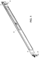
- the slide rail assembly 20 in an embodiment of the present invention is detachably attached to a first post 26 and a second post 28 of a rack via a first bracket 22 and a second bracket 24 respectively.
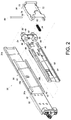
- the slide rail assembly 20 further includes a rail 30 and a supporting frame 32.
- the supporting frame 32 is fixedly connected to the rail 30 and can therefore be viewed as a part of the rail 30.
- the supporting frame 32 has an upper wall 38a, a lower wall 38b, and a longitudinal wall 40 connected between the upper wall 38a and the lower wall 38b.
- the upper wall 38a, the lower wall 38b, and the longitudinal wall 40 jointly define a channel 42.
- the longitudinal wall 40 includes a first portion 44 (e.g., a protruding block) provided in the channel 42.
- the first bracket 22 is mounted to the rail 30 at a position adjacent to a first end portion 31a of the rail 30.
- the second bracket 24 is movably connected to the rail 30 and can be displaced along the rail 30 to a position adjacent to a second end portion 31b of the rail 30. More specifically, the second bracket 24 includes a side plate 46, an end plate 48, at least one attaching member 50, an elastic member 34, and a hook 36.
- the side plate 46 is movably mounted to the rail 30.
- the side plate 46 is fixedly connected with an extension member 52 and is movably mounted in the channel 42 of the supporting frame 32, wherein the extension member 52 includes a second portion 54.
- the side plate 46 has a pair of ears 56 and a first mounting feature 58 located between the ears 56.
- the pair of ears 56 extend from and are bent with respect to the side plate 46.
- One of the second bracket 24 and the hook 36 has a guiding portion 60, such as a longitudinal hole.
- each ear 56 of the second bracket 24 is provided with the guiding portion 60.
- the end plate 48 is substantially perpendicularly connected to the side plate 46.
- the at least one attaching member 50 is mounted on the end plate 48.
- the second bracket 24 further includes a second mounting feature 62 opposite the first mounting feature 58.
- the elastic member 34 is arranged between the first mounting feature 58 and the second mounting feature 62.
- the hook 36 is movably connected to the second bracket 24. In this embodiment, the hook 36 is connected to the guiding portions 60 via a connector 64 for example.
- the hook 36 is movably connected to the second bracket 24.
- the elastic member 34 has a first section 66a and a second section 66b corresponding in position to the first section 66a and is mounted between the first mounting feature 58 and the second mounting feature 62.
- each ear 56 of the side plate 46 of the second bracket 24 has a projecting section 68 and a recessed section 70 adjacent to the projecting section 68.
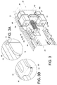
- the hook 36 has a pair of blocking portions 72. The pair of blocking portions 72 can be provided adjacent to the at least one attaching member 50. As shown in FIG. 3 and FIG.
- the second bracket 24 has a first contact portion 74 arranged on the side plate 46, and the hook 36 has a second contact portion 76 corresponding to the first contact portion 74.
- One of the first contact portion 74 and the second contact portion 76 includes an inclined guide surface 78. In this embodiment, for example, it is the second contact portion 76 that includes the inclined guide surface 78.
- the second bracket 24 further has a first pressing portion 80 arranged on each ear 56, and the hook 36 further has a second pressing portion 82 corresponding to the first pressing portions 80.
- Each first pressing portion 80 or the second pressing portion 82 includes an inclined guide section 84. In this embodiment, for example, each first pressing portion 80 includes the inclined guide section 84.
- the second bracket 24 is attached to a hole 88 in the second post 28 via the at least one attaching member 50.
- the elastic member 34 applies an elastic force to the hook 36 so that the hook 36 can stay at a locked position P in response to the elastic force of the elastic member 34.
- the hook 36 has a mounting portion 90 mounted between the first section 66a and the second section 66b of the elastic member 34 (see also FIG. 4A ) in order to keep the hook 36 at the locked position P with respect to the second bracket 24, with the blocking portions 72 of the hook 36 corresponding to the second post 28.
- Each guiding portion 60 has a predetermined length L (e.g., a predetermined longitudinal length) for limiting displacement of the second bracket 24 with respect to the hook 36.
- the first portion 44 corresponds to the second portion 54 (see also FIG. 4B ).
- the operator applies a force to the rail 30 to displace the rail 30 in a first direction D1.
- the rail 30 drives the second bracket 24 into displacement in the first direction D1 such that the blocking portions 72 of the hook 36 are pressed against the second post 28.
- the second bracket 24 is further displaced in the first direction D1 such that the first contact portion 74 of the second bracket 24 is pressed against the second contact portion 76 of the hook 36 (see also FIG. 8A and FIG. 9A ).
- the hook 36 is tilted by an angle with respect to the second bracket 24 and leaves the locked position P, and the blocking portions 72 of the hook 36 are no more pressed against the second post 28.
- the at least one attaching member 50 of the second bracket 24 can now be disengaged from the hole 88 in the second post 28, allowing the slide rail assembly 20 to separate from the second post 28.
- the operator can detach the slide rail assembly 20 from the first post 26 and the second post 28 while standing near the first post 26, and the entire process can be completed easily and rapidly.
- the operator stands near the first post 26 (see also FIG. 5 ) and displaces the rail 30 in a second direction D2 toward the second post 28, with the at least one attaching member 50 of the second bracket 24 corresponding to the hole 88 in the second post 28.
- the blocking portions 72 of the hook 36 end up pressed against the second post 28.
- the first pressing portions 80 of the second bracket 24 are pressed against the second pressing portion 82 of the hook 36 such that the hook 36 is tilted by an angle with respect to the second bracket 24. Certain portions of the hook 36 are now in the recessed sections 70 of the ears 56 respectively.
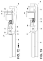
- the hook 36 When the rail 30 is further displaced in the second direction D2, as shown in FIG. 12 and FIG. 13 , the hook 36 is tilted back in place with respect to the second bracket 24 by the aforesaid angle, with the blocking portions 72 of the hook 36 located on the far side of the second post 28, and the at least one attaching member 50 of the second bracket 24 attached to the hole 88 in the second post 28.
- the assembly process is completed. It is worth mentioning that the hook 36 eventually returns to the locked position with respect to the second bracket 24 thanks to the mounting portion 90 responding to the elastic force of the elastic member 34, and in consequence the blocking portions 72 of the hook 36 correspond to the second post 28.
- certain portions of the hook 36 correspond to the projecting sections 68 respectively to ensure that the blocking portions 72 of the hook 36 stay corresponding to the second post 28. As such, a locking function is achieved which prevents the hook 36 from tilting should the hook 36 be subjected to an unwanted external force.
Landscapes
- Engineering & Computer Science (AREA)
- Computer Hardware Design (AREA)
- General Engineering & Computer Science (AREA)
- Microelectronics & Electronic Packaging (AREA)
- Drawers Of Furniture (AREA)
- Seats For Vehicles (AREA)
Applications Claiming Priority (1)
| Application Number | Priority Date | Filing Date | Title |
|---|---|---|---|
| TW104128887A TWI598024B (zh) | 2015-08-31 | 2015-08-31 | 滑軌總成及其托架 |
Publications (3)
| Publication Number | Publication Date |
|---|---|
| EP3136830A2 true EP3136830A2 (de) | 2017-03-01 |
| EP3136830A3 EP3136830A3 (de) | 2017-03-08 |
| EP3136830B1 EP3136830B1 (de) | 2018-02-28 |
Family
ID=55527787
Family Applications (1)
| Application Number | Title | Priority Date | Filing Date |
|---|---|---|---|
| EP16158662.3A Active EP3136830B1 (de) | 2015-08-31 | 2016-03-04 | Gleitschienenanordnung und klammer dafür |
Country Status (4)
| Country | Link |
|---|---|
| US (1) | US9986828B2 (de) |
| EP (1) | EP3136830B1 (de) |
| JP (1) | JP6284969B2 (de) |
| TW (1) | TWI598024B (de) |
Cited By (5)
| Publication number | Priority date | Publication date | Assignee | Title |
|---|---|---|---|---|
| EP3457827A1 (de) * | 2017-09-15 | 2019-03-20 | King Slide Works Co., Ltd. | Gleitschienenanordnung und haltevorrichtung dafür |
| EP3493661A1 (de) * | 2017-12-01 | 2019-06-05 | King Slide Works Co., Ltd. | Traganordnung für gestell |
| CN110139523A (zh) * | 2018-02-09 | 2019-08-16 | 川湖科技股份有限公司 | 用于理线装置与滑轨总成的连接装置 |
| EP3537857A1 (de) * | 2018-03-08 | 2019-09-11 | King Slide Works Co., Ltd. | Gleitschienenanordnung und haltevorrichtung damit |
| CN115701754A (zh) * | 2021-08-02 | 2023-02-10 | 川湖科技股份有限公司 | 支撑装置 |
Families Citing this family (13)
| Publication number | Priority date | Publication date | Assignee | Title |
|---|---|---|---|---|
| TWI594681B (zh) * | 2016-06-06 | 2017-08-01 | Bracket change positioning device | |
| USD858263S1 (en) * | 2016-06-16 | 2019-09-03 | Martas Precision Slide Co., Ltd. | Connector |
| USD884463S1 (en) * | 2016-06-16 | 2020-05-19 | Martas Precision Slide Co., Ltd. | Connector |
| TWI600392B (zh) * | 2016-07-13 | 2017-10-01 | 川湖科技股份有限公司 | 托架裝置 |
| TWI624210B (zh) * | 2016-11-01 | 2018-05-11 | 川湖科技股份有限公司 | 托架裝置 |
| TWI633859B (zh) * | 2017-02-09 | 2018-09-01 | 川湖科技股份有限公司 | 滑軌機構及其托架裝置 |
| CN108720378A (zh) * | 2017-04-14 | 2018-11-02 | 新代产品公司 | 具有调节机构的柜组件 |
| US10070555B1 (en) * | 2017-08-31 | 2018-09-04 | Martas Precision Slide Co., Ltd. | Insertable fixing module of cabinet rail |
| TWI665984B (zh) * | 2017-10-11 | 2019-07-21 | 振躍精密滑軌股份有限公司 | 滑軌托架 |
| CN109874247B (zh) * | 2017-12-05 | 2020-06-23 | 川湖科技股份有限公司 | 可用于机柜的支撑总成 |
| USD892523S1 (en) * | 2017-12-22 | 2020-08-11 | Julius Blum Gmbh | Drawer part |
| US10645826B1 (en) * | 2019-07-23 | 2020-05-05 | Martas Precision Slide Co., Ltd. | Elastic clamping fastener module of industrial cabinet rail |
| CN112333969B (zh) * | 2019-08-05 | 2022-03-22 | 启碁科技股份有限公司 | 柜体 |
Citations (1)
| Publication number | Priority date | Publication date | Assignee | Title |
|---|---|---|---|---|
| CN102695396B (zh) | 2011-03-23 | 2014-12-24 | 雅固拉国际精密工业(苏州)有限公司 | 一种服务器用滑轨免工具安装支架 |
Family Cites Families (18)
| Publication number | Priority date | Publication date | Assignee | Title |
|---|---|---|---|---|
| US7192103B2 (en) | 2002-07-19 | 2007-03-20 | Ergo 2000, Inc. | Spring loaded bracket assembly having a tool-less attachment and removal feature |
| TWM255624U (en) * | 2003-12-30 | 2005-01-11 | King Slide Works Co Ltd | Positioning device for sliding track bracket |
| US8146756B2 (en) | 2007-04-18 | 2012-04-03 | Jonathan Manufacturing Corporation | Universal toolless rack mount bracket |
| US7731142B2 (en) | 2007-12-28 | 2010-06-08 | King Slide Works Co., Ltd. | Tool-less mounting slide bracket |
| CN101558944B (zh) * | 2008-04-16 | 2011-07-27 | 鸿富锦精密工业(深圳)有限公司 | 滑轨固定装置 |
| CN102197925A (zh) * | 2010-03-24 | 2011-09-28 | 鸿富锦精密工业(深圳)有限公司 | 滑轨安装装置 |
| TW201311184A (zh) * | 2011-09-05 | 2013-03-16 | Hon Hai Prec Ind Co Ltd | 滑軌固定裝置 |
| US8727138B2 (en) * | 2011-11-04 | 2014-05-20 | International Business Machines Corporation | Toolless rail enabling simplified installation and removal |
| US9144173B2 (en) * | 2013-02-06 | 2015-09-22 | King Slide Works Co., Ltd. | Slide rail assembly for use in rack system and reinforcement member thereof |
| US20150048227A1 (en) * | 2013-08-19 | 2015-02-19 | Bin Yuann Firstline Industrial Corp. | Rail bracket securing structure |
| US9107322B2 (en) * | 2013-08-19 | 2015-08-11 | Bin Yuann Firstline Industrial Corp. | Fast rail bracket securing structure for server |
| EP2893838B1 (de) * | 2014-01-09 | 2016-05-04 | King Slide Works Co., Ltd. | Schiebeanordnung mit einem verstellbaren Beschlag |
| TWI624208B (zh) * | 2015-05-05 | 2018-05-11 | 川湖科技股份有限公司 | 托架裝置 |
| TWI561153B (en) * | 2015-10-06 | 2016-12-01 | King Slide Works Co Ltd | Slide rail assembly with bracket |
| TWI577314B (zh) * | 2016-02-05 | 2017-04-11 | 川湖科技股份有限公司 | 托架裝置 |
| US10617029B2 (en) * | 2016-04-12 | 2020-04-07 | King Slide Works Co., Ltd. | Bracket device |
| US20170354055A1 (en) * | 2016-06-03 | 2017-12-07 | Kunshan Lemtech SlideTechnology Co., Ltd. | Quick Release Device for a Slide Track |
| TWI600392B (zh) * | 2016-07-13 | 2017-10-01 | 川湖科技股份有限公司 | 托架裝置 |
-
2015
- 2015-08-31 TW TW104128887A patent/TWI598024B/zh active
-
2016
- 2016-02-25 US US15/053,069 patent/US9986828B2/en active Active
- 2016-03-04 EP EP16158662.3A patent/EP3136830B1/de active Active
- 2016-03-14 JP JP2016049459A patent/JP6284969B2/ja active Active
Patent Citations (1)
| Publication number | Priority date | Publication date | Assignee | Title |
|---|---|---|---|---|
| CN102695396B (zh) | 2011-03-23 | 2014-12-24 | 雅固拉国际精密工业(苏州)有限公司 | 一种服务器用滑轨免工具安装支架 |
Cited By (8)
| Publication number | Priority date | Publication date | Assignee | Title |
|---|---|---|---|---|
| EP3457827A1 (de) * | 2017-09-15 | 2019-03-20 | King Slide Works Co., Ltd. | Gleitschienenanordnung und haltevorrichtung dafür |
| EP3493661A1 (de) * | 2017-12-01 | 2019-06-05 | King Slide Works Co., Ltd. | Traganordnung für gestell |
| CN110139523A (zh) * | 2018-02-09 | 2019-08-16 | 川湖科技股份有限公司 | 用于理线装置与滑轨总成的连接装置 |
| CN110139523B (zh) * | 2018-02-09 | 2020-08-04 | 川湖科技股份有限公司 | 用于理线装置与滑轨总成的连接装置 |
| EP3537857A1 (de) * | 2018-03-08 | 2019-09-11 | King Slide Works Co., Ltd. | Gleitschienenanordnung und haltevorrichtung damit |
| US10765207B2 (en) | 2018-03-08 | 2020-09-08 | King Slide Works Co., Ltd. | Slide rail assembly and bracket device thereof |
| US10881203B2 (en) | 2018-03-08 | 2021-01-05 | King Slide Works Co., Ltd. | Slide rail assembly and bracket device thereof |
| CN115701754A (zh) * | 2021-08-02 | 2023-02-10 | 川湖科技股份有限公司 | 支撑装置 |
Also Published As
| Publication number | Publication date |
|---|---|
| TWI598024B (zh) | 2017-09-01 |
| EP3136830B1 (de) | 2018-02-28 |
| JP6284969B2 (ja) | 2018-02-28 |
| EP3136830A3 (de) | 2017-03-08 |
| US9986828B2 (en) | 2018-06-05 |
| JP2017047166A (ja) | 2017-03-09 |
| TW201709800A (zh) | 2017-03-01 |
| US20170055707A1 (en) | 2017-03-02 |
Similar Documents
| Publication | Publication Date | Title |
|---|---|---|
| EP3136830B1 (de) | Gleitschienenanordnung und klammer dafür | |
| EP3131375B1 (de) | Gleitschienenanordnung und haltevorrichtung dafür | |
| EP3148304B1 (de) | Gleitschienenanordnung und haltevorrichtung dafür | |
| US10455938B2 (en) | Slide rail assembly | |
| US10357105B2 (en) | Coupling assembly and bracket device thereof | |
| EP3082387B1 (de) | Gleitschienenanordnung | |
| US10194556B2 (en) | Slide rail mechanism and bracket device thereof | |
| EP3310138B1 (de) | Klammervorrichtung | |
| US9375087B1 (en) | Bracket and mounting device thereof | |
| US7703734B2 (en) | Slide mounting bracket structure | |
| US9629459B2 (en) | Slide rail assembly | |
| US9383038B2 (en) | Cable management arm supporting device and mounting assembly thereof | |
| US10149538B2 (en) | Slide rail mechanism | |
| EP3041329A1 (de) | Kabelmanagementarm | |
| EP3030065B1 (de) | Armstützvorrichtung zur Kabelverwaltung und Montageanordnung dafür | |
| EP3032930B1 (de) | Klammer und Montagevorrichtung dafür | |
| EP3071003B1 (de) | Schienenanordnung | |
| US20200187646A1 (en) | Bracket device |
Legal Events
| Date | Code | Title | Description |
|---|---|---|---|
| PUAI | Public reference made under article 153(3) epc to a published international application that has entered the european phase |
Free format text: ORIGINAL CODE: 0009012 |
|
| PUAL | Search report despatched |
Free format text: ORIGINAL CODE: 0009013 |
|
| AK | Designated contracting states |
Kind code of ref document: A2 Designated state(s): AL AT BE BG CH CY CZ DE DK EE ES FI FR GB GR HR HU IE IS IT LI LT LU LV MC MK MT NL NO PL PT RO RS SE SI SK SM TR |
|
| AX | Request for extension of the european patent |
Extension state: BA ME |
|
| AK | Designated contracting states |
Kind code of ref document: A3 Designated state(s): AL AT BE BG CH CY CZ DE DK EE ES FI FR GB GR HR HU IE IS IT LI LT LU LV MC MK MT NL NO PL PT RO RS SE SI SK SM TR |
|
| AX | Request for extension of the european patent |
Extension state: BA ME |
|
| RIC1 | Information provided on ipc code assigned before grant |
Ipc: H05K 7/14 20060101AFI20170201BHEP |
|
| 17P | Request for examination filed |
Effective date: 20170517 |
|
| RBV | Designated contracting states (corrected) |
Designated state(s): AL AT BE BG CH CY CZ DE DK EE ES FI FR GB GR HR HU IE IS IT LI LT LU LV MC MK MT NL NO PL PT RO RS SE SI SK SM TR |
|
| GRAP | Despatch of communication of intention to grant a patent |
Free format text: ORIGINAL CODE: EPIDOSNIGR1 |
|
| INTG | Intention to grant announced |
Effective date: 20170922 |
|
| GRAS | Grant fee paid |
Free format text: ORIGINAL CODE: EPIDOSNIGR3 |
|
| GRAA | (expected) grant |
Free format text: ORIGINAL CODE: 0009210 |
|
| AK | Designated contracting states |
Kind code of ref document: B1 Designated state(s): AL AT BE BG CH CY CZ DE DK EE ES FI FR GB GR HR HU IE IS IT LI LT LU LV MC MK MT NL NO PL PT RO RS SE SI SK SM TR |
|
| REG | Reference to a national code |
Ref country code: GB Ref legal event code: FG4D Ref country code: CH Ref legal event code: EP |
|
| REG | Reference to a national code |
Ref country code: AT Ref legal event code: REF Ref document number: 975508 Country of ref document: AT Kind code of ref document: T Effective date: 20180315 |
|
| REG | Reference to a national code |
Ref country code: IE Ref legal event code: FG4D |
|
| REG | Reference to a national code |
Ref country code: DE Ref legal event code: R096 Ref document number: 602016001666 Country of ref document: DE |
|
| REG | Reference to a national code |
Ref country code: NL Ref legal event code: MP Effective date: 20180228 |
|
| REG | Reference to a national code |
Ref country code: LT Ref legal event code: MG4D |
|
| REG | Reference to a national code |
Ref country code: AT Ref legal event code: MK05 Ref document number: 975508 Country of ref document: AT Kind code of ref document: T Effective date: 20180228 |
|
| PG25 | Lapsed in a contracting state [announced via postgrant information from national office to epo] |
Ref country code: FI Free format text: LAPSE BECAUSE OF FAILURE TO SUBMIT A TRANSLATION OF THE DESCRIPTION OR TO PAY THE FEE WITHIN THE PRESCRIBED TIME-LIMIT Effective date: 20180228 Ref country code: NO Free format text: LAPSE BECAUSE OF FAILURE TO SUBMIT A TRANSLATION OF THE DESCRIPTION OR TO PAY THE FEE WITHIN THE PRESCRIBED TIME-LIMIT Effective date: 20180528 Ref country code: HR Free format text: LAPSE BECAUSE OF FAILURE TO SUBMIT A TRANSLATION OF THE DESCRIPTION OR TO PAY THE FEE WITHIN THE PRESCRIBED TIME-LIMIT Effective date: 20180228 Ref country code: CY Free format text: LAPSE BECAUSE OF FAILURE TO SUBMIT A TRANSLATION OF THE DESCRIPTION OR TO PAY THE FEE WITHIN THE PRESCRIBED TIME-LIMIT Effective date: 20180228 Ref country code: NL Free format text: LAPSE BECAUSE OF FAILURE TO SUBMIT A TRANSLATION OF THE DESCRIPTION OR TO PAY THE FEE WITHIN THE PRESCRIBED TIME-LIMIT Effective date: 20180228 Ref country code: LT Free format text: LAPSE BECAUSE OF FAILURE TO SUBMIT A TRANSLATION OF THE DESCRIPTION OR TO PAY THE FEE WITHIN THE PRESCRIBED TIME-LIMIT Effective date: 20180228 Ref country code: ES Free format text: LAPSE BECAUSE OF FAILURE TO SUBMIT A TRANSLATION OF THE DESCRIPTION OR TO PAY THE FEE WITHIN THE PRESCRIBED TIME-LIMIT Effective date: 20180228 |
|
| PG25 | Lapsed in a contracting state [announced via postgrant information from national office to epo] |
Ref country code: BG Free format text: LAPSE BECAUSE OF FAILURE TO SUBMIT A TRANSLATION OF THE DESCRIPTION OR TO PAY THE FEE WITHIN THE PRESCRIBED TIME-LIMIT Effective date: 20180528 Ref country code: LV Free format text: LAPSE BECAUSE OF FAILURE TO SUBMIT A TRANSLATION OF THE DESCRIPTION OR TO PAY THE FEE WITHIN THE PRESCRIBED TIME-LIMIT Effective date: 20180228 Ref country code: SE Free format text: LAPSE BECAUSE OF FAILURE TO SUBMIT A TRANSLATION OF THE DESCRIPTION OR TO PAY THE FEE WITHIN THE PRESCRIBED TIME-LIMIT Effective date: 20180228 Ref country code: RS Free format text: LAPSE BECAUSE OF FAILURE TO SUBMIT A TRANSLATION OF THE DESCRIPTION OR TO PAY THE FEE WITHIN THE PRESCRIBED TIME-LIMIT Effective date: 20180228 Ref country code: AT Free format text: LAPSE BECAUSE OF FAILURE TO SUBMIT A TRANSLATION OF THE DESCRIPTION OR TO PAY THE FEE WITHIN THE PRESCRIBED TIME-LIMIT Effective date: 20180228 Ref country code: GR Free format text: LAPSE BECAUSE OF FAILURE TO SUBMIT A TRANSLATION OF THE DESCRIPTION OR TO PAY THE FEE WITHIN THE PRESCRIBED TIME-LIMIT Effective date: 20180529 |
|
| PG25 | Lapsed in a contracting state [announced via postgrant information from national office to epo] |
Ref country code: IT Free format text: LAPSE BECAUSE OF FAILURE TO SUBMIT A TRANSLATION OF THE DESCRIPTION OR TO PAY THE FEE WITHIN THE PRESCRIBED TIME-LIMIT Effective date: 20180228 Ref country code: RO Free format text: LAPSE BECAUSE OF FAILURE TO SUBMIT A TRANSLATION OF THE DESCRIPTION OR TO PAY THE FEE WITHIN THE PRESCRIBED TIME-LIMIT Effective date: 20180228 Ref country code: EE Free format text: LAPSE BECAUSE OF FAILURE TO SUBMIT A TRANSLATION OF THE DESCRIPTION OR TO PAY THE FEE WITHIN THE PRESCRIBED TIME-LIMIT Effective date: 20180228 Ref country code: AL Free format text: LAPSE BECAUSE OF FAILURE TO SUBMIT A TRANSLATION OF THE DESCRIPTION OR TO PAY THE FEE WITHIN THE PRESCRIBED TIME-LIMIT Effective date: 20180228 Ref country code: PL Free format text: LAPSE BECAUSE OF FAILURE TO SUBMIT A TRANSLATION OF THE DESCRIPTION OR TO PAY THE FEE WITHIN THE PRESCRIBED TIME-LIMIT Effective date: 20180228 |
|
| REG | Reference to a national code |
Ref country code: DE Ref legal event code: R097 Ref document number: 602016001666 Country of ref document: DE |
|
| PG25 | Lapsed in a contracting state [announced via postgrant information from national office to epo] |
Ref country code: DK Free format text: LAPSE BECAUSE OF FAILURE TO SUBMIT A TRANSLATION OF THE DESCRIPTION OR TO PAY THE FEE WITHIN THE PRESCRIBED TIME-LIMIT Effective date: 20180228 Ref country code: SK Free format text: LAPSE BECAUSE OF FAILURE TO SUBMIT A TRANSLATION OF THE DESCRIPTION OR TO PAY THE FEE WITHIN THE PRESCRIBED TIME-LIMIT Effective date: 20180228 Ref country code: MC Free format text: LAPSE BECAUSE OF FAILURE TO SUBMIT A TRANSLATION OF THE DESCRIPTION OR TO PAY THE FEE WITHIN THE PRESCRIBED TIME-LIMIT Effective date: 20180228 Ref country code: CZ Free format text: LAPSE BECAUSE OF FAILURE TO SUBMIT A TRANSLATION OF THE DESCRIPTION OR TO PAY THE FEE WITHIN THE PRESCRIBED TIME-LIMIT Effective date: 20180228 Ref country code: SM Free format text: LAPSE BECAUSE OF FAILURE TO SUBMIT A TRANSLATION OF THE DESCRIPTION OR TO PAY THE FEE WITHIN THE PRESCRIBED TIME-LIMIT Effective date: 20180228 |
|
| REG | Reference to a national code |
Ref country code: BE Ref legal event code: MM Effective date: 20180331 |
|
| PG25 | Lapsed in a contracting state [announced via postgrant information from national office to epo] |
Ref country code: LU Free format text: LAPSE BECAUSE OF NON-PAYMENT OF DUE FEES Effective date: 20180304 |
|
| PLBE | No opposition filed within time limit |
Free format text: ORIGINAL CODE: 0009261 |
|
| STAA | Information on the status of an ep patent application or granted ep patent |
Free format text: STATUS: NO OPPOSITION FILED WITHIN TIME LIMIT |
|
| 26N | No opposition filed |
Effective date: 20181129 |
|
| PG25 | Lapsed in a contracting state [announced via postgrant information from national office to epo] |
Ref country code: BE Free format text: LAPSE BECAUSE OF NON-PAYMENT OF DUE FEES Effective date: 20180331 Ref country code: SI Free format text: LAPSE BECAUSE OF FAILURE TO SUBMIT A TRANSLATION OF THE DESCRIPTION OR TO PAY THE FEE WITHIN THE PRESCRIBED TIME-LIMIT Effective date: 20180228 |
|
| PG25 | Lapsed in a contracting state [announced via postgrant information from national office to epo] |
Ref country code: FR Free format text: LAPSE BECAUSE OF NON-PAYMENT OF DUE FEES Effective date: 20180428 |
|
| REG | Reference to a national code |
Ref country code: CH Ref legal event code: PL |
|
| PG25 | Lapsed in a contracting state [announced via postgrant information from national office to epo] |
Ref country code: CH Free format text: LAPSE BECAUSE OF NON-PAYMENT OF DUE FEES Effective date: 20190331 Ref country code: LI Free format text: LAPSE BECAUSE OF NON-PAYMENT OF DUE FEES Effective date: 20190331 Ref country code: MT Free format text: LAPSE BECAUSE OF NON-PAYMENT OF DUE FEES Effective date: 20180304 |
|
| PG25 | Lapsed in a contracting state [announced via postgrant information from national office to epo] |
Ref country code: TR Free format text: LAPSE BECAUSE OF FAILURE TO SUBMIT A TRANSLATION OF THE DESCRIPTION OR TO PAY THE FEE WITHIN THE PRESCRIBED TIME-LIMIT Effective date: 20180228 |
|
| PG25 | Lapsed in a contracting state [announced via postgrant information from national office to epo] |
Ref country code: PT Free format text: LAPSE BECAUSE OF FAILURE TO SUBMIT A TRANSLATION OF THE DESCRIPTION OR TO PAY THE FEE WITHIN THE PRESCRIBED TIME-LIMIT Effective date: 20180228 |
|
| PG25 | Lapsed in a contracting state [announced via postgrant information from national office to epo] |
Ref country code: MK Free format text: LAPSE BECAUSE OF NON-PAYMENT OF DUE FEES Effective date: 20180228 Ref country code: HU Free format text: LAPSE BECAUSE OF FAILURE TO SUBMIT A TRANSLATION OF THE DESCRIPTION OR TO PAY THE FEE WITHIN THE PRESCRIBED TIME-LIMIT; INVALID AB INITIO Effective date: 20160304 |
|
| PG25 | Lapsed in a contracting state [announced via postgrant information from national office to epo] |
Ref country code: IS Free format text: LAPSE BECAUSE OF FAILURE TO SUBMIT A TRANSLATION OF THE DESCRIPTION OR TO PAY THE FEE WITHIN THE PRESCRIBED TIME-LIMIT Effective date: 20180628 |
|
| PGFP | Annual fee paid to national office [announced via postgrant information from national office to epo] |
Ref country code: GB Payment date: 20260108 Year of fee payment: 11 |
|
| PGFP | Annual fee paid to national office [announced via postgrant information from national office to epo] |
Ref country code: DE Payment date: 20260109 Year of fee payment: 11 Ref country code: IE Payment date: 20260108 Year of fee payment: 11 |