EP3136724B1 - Wearable display apparatus, information processing apparatus, and control method therefor - Google Patents
Wearable display apparatus, information processing apparatus, and control method therefor Download PDFInfo
- Publication number
- EP3136724B1 EP3136724B1 EP16001705.9A EP16001705A EP3136724B1 EP 3136724 B1 EP3136724 B1 EP 3136724B1 EP 16001705 A EP16001705 A EP 16001705A EP 3136724 B1 EP3136724 B1 EP 3136724B1
- Authority
- EP
- European Patent Office
- Prior art keywords
- cameras
- image capturing
- capturing means
- observer
- display apparatus
- Prior art date
- Legal status (The legal status is an assumption and is not a legal conclusion. Google has not performed a legal analysis and makes no representation as to the accuracy of the status listed.)
- Active
Links
Images

Classifications
-
- G—PHYSICS
- G06—COMPUTING; CALCULATING OR COUNTING
- G06T—IMAGE DATA PROCESSING OR GENERATION, IN GENERAL
- G06T19/00—Manipulating 3D models or images for computer graphics
- G06T19/006—Mixed reality
-
- H—ELECTRICITY
- H04—ELECTRIC COMMUNICATION TECHNIQUE
- H04N—PICTORIAL COMMUNICATION, e.g. TELEVISION
- H04N13/00—Stereoscopic video systems; Multi-view video systems; Details thereof
- H04N13/20—Image signal generators
- H04N13/204—Image signal generators using stereoscopic image cameras
- H04N13/243—Image signal generators using stereoscopic image cameras using three or more 2D image sensors
-
- G—PHYSICS
- G02—OPTICS
- G02B—OPTICAL ELEMENTS, SYSTEMS OR APPARATUS
- G02B27/00—Optical systems or apparatus not provided for by any of the groups G02B1/00 - G02B26/00, G02B30/00
- G02B27/01—Head-up displays
- G02B27/017—Head mounted
- G02B27/0176—Head mounted characterised by mechanical features
-
- G—PHYSICS
- G06—COMPUTING; CALCULATING OR COUNTING
- G06T—IMAGE DATA PROCESSING OR GENERATION, IN GENERAL
- G06T19/00—Manipulating 3D models or images for computer graphics
- G06T19/003—Navigation within 3D models or images
-
- H—ELECTRICITY
- H04—ELECTRIC COMMUNICATION TECHNIQUE
- H04N—PICTORIAL COMMUNICATION, e.g. TELEVISION
- H04N13/00—Stereoscopic video systems; Multi-view video systems; Details thereof
- H04N13/10—Processing, recording or transmission of stereoscopic or multi-view image signals
- H04N13/106—Processing image signals
- H04N13/156—Mixing image signals
-
- H—ELECTRICITY
- H04—ELECTRIC COMMUNICATION TECHNIQUE
- H04N—PICTORIAL COMMUNICATION, e.g. TELEVISION
- H04N13/00—Stereoscopic video systems; Multi-view video systems; Details thereof
- H04N13/20—Image signal generators
- H04N13/204—Image signal generators using stereoscopic image cameras
- H04N13/239—Image signal generators using stereoscopic image cameras using two 2D image sensors having a relative position equal to or related to the interocular distance
-
- H—ELECTRICITY
- H04—ELECTRIC COMMUNICATION TECHNIQUE
- H04N—PICTORIAL COMMUNICATION, e.g. TELEVISION
- H04N13/00—Stereoscopic video systems; Multi-view video systems; Details thereof
- H04N13/20—Image signal generators
- H04N13/275—Image signal generators from 3D object models, e.g. computer-generated stereoscopic image signals
- H04N13/279—Image signal generators from 3D object models, e.g. computer-generated stereoscopic image signals the virtual viewpoint locations being selected by the viewers or determined by tracking
-
- H—ELECTRICITY
- H04—ELECTRIC COMMUNICATION TECHNIQUE
- H04N—PICTORIAL COMMUNICATION, e.g. TELEVISION
- H04N13/00—Stereoscopic video systems; Multi-view video systems; Details thereof
- H04N13/30—Image reproducers
- H04N13/332—Displays for viewing with the aid of special glasses or head-mounted displays [HMD]
- H04N13/344—Displays for viewing with the aid of special glasses or head-mounted displays [HMD] with head-mounted left-right displays
-
- H—ELECTRICITY
- H04—ELECTRIC COMMUNICATION TECHNIQUE
- H04N—PICTORIAL COMMUNICATION, e.g. TELEVISION
- H04N13/00—Stereoscopic video systems; Multi-view video systems; Details thereof
- H04N13/30—Image reproducers
- H04N13/366—Image reproducers using viewer tracking
-
- H—ELECTRICITY
- H04—ELECTRIC COMMUNICATION TECHNIQUE
- H04N—PICTORIAL COMMUNICATION, e.g. TELEVISION
- H04N13/00—Stereoscopic video systems; Multi-view video systems; Details thereof
- H04N13/30—Image reproducers
- H04N13/366—Image reproducers using viewer tracking
- H04N13/383—Image reproducers using viewer tracking for tracking with gaze detection, i.e. detecting the lines of sight of the viewer's eyes
-
- G—PHYSICS
- G02—OPTICS
- G02B—OPTICAL ELEMENTS, SYSTEMS OR APPARATUS
- G02B27/00—Optical systems or apparatus not provided for by any of the groups G02B1/00 - G02B26/00, G02B30/00
- G02B27/01—Head-up displays
- G02B27/0101—Head-up displays characterised by optical features
- G02B2027/0138—Head-up displays characterised by optical features comprising image capture systems, e.g. camera
-
- G—PHYSICS
- G02—OPTICS
- G02B—OPTICAL ELEMENTS, SYSTEMS OR APPARATUS
- G02B27/00—Optical systems or apparatus not provided for by any of the groups G02B1/00 - G02B26/00, G02B30/00
- G02B27/01—Head-up displays
- G02B27/0101—Head-up displays characterised by optical features
- G02B2027/014—Head-up displays characterised by optical features comprising information/image processing systems
-
- G—PHYSICS
- G02—OPTICS
- G02B—OPTICAL ELEMENTS, SYSTEMS OR APPARATUS
- G02B27/00—Optical systems or apparatus not provided for by any of the groups G02B1/00 - G02B26/00, G02B30/00
- G02B27/01—Head-up displays
- G02B27/0179—Display position adjusting means not related to the information to be displayed
- G02B2027/0187—Display position adjusting means not related to the information to be displayed slaved to motion of at least a part of the body of the user, e.g. head, eye
-
- G—PHYSICS
- G06—COMPUTING; CALCULATING OR COUNTING
- G06T—IMAGE DATA PROCESSING OR GENERATION, IN GENERAL
- G06T2200/00—Indexing scheme for image data processing or generation, in general
- G06T2200/04—Indexing scheme for image data processing or generation, in general involving 3D image data
Definitions
- the present invention relates to a wearable display apparatus represented by an HMD (Head Mounted Display), an information processing apparatus connected to the wearable display apparatus, and a control method for the information processing apparatus.
- HMD Head Mounted Display
- HMD head mounted display
- MR mixed reality
- the HMD for implementing MR includes an image capturing unit for capturing images of an object in correspondence with the right and left eyes of the observer.
- the HMD also includes display units for respectively superimposing and displaying the images shot by the image capturing unit and 3D-CG object images created by a PC or the like, and observation optical systems for projecting the images on the observer.
- Videos projected on the observer are displayed on display devices such as small liquid crystal panels corresponding to the right and left eyes of the observer.
- the videos are enlarged via the observation optical systems respectively corresponding to the right and left eyes of the observer, and projected on the right and left eyeballs of the observer.
- the shot images of the object have a parallax corresponding to the right and left eyes. Furthermore, images each representing the 3D-CG object are created as parallax images corresponding to the right and left eyes of the observer, and then superimposed and displayed on the videos captured by an imaging system. As a result, the observer visually perceives the 3D-CG object as if it existed in a physical space. In this point, the 3D-CG object is also called a virtual object.
- US 2002/0075201 A1 discloses a head-mounted display system comprising an imaging camera for capturing a workspace and a tracking camera aligned at a similar yaw as the imaging camera for capturing a tracking image including a marker structure.
- US 2005/0203380 A1 and US 2007/0273610 A1 also relate to head mounted displays including at least one tracking camera.
- JP 2004-205711 A discloses a head mounted display including a pair of tracking cameras.
- Japanese Patent No. 3363861 discloses a technique of controlling a sensor as a method of detecting the position and orientation of an HMD.
- literature 1 discloses a technique of controlling a sensor as a method of detecting the position and orientation of an HMD.
- separately including a sensor increases components, and thus an increase in weight and an increase in cost caused by the increase in components are concerned.
- Japanese Patent Laid-Open No. 2011-205358 discloses a method in which the image capturing unit of an HMD acquires a video having a wide angle of view, and provides the video having undergone distortion correction to an observer.
- a method of displaying part of a video having a wide angle of view leads to a decrease in resolution, thereby degrading the quality of the video provided to the observer.
- the present invention in its first aspect provides a wearable display apparatus as specified in claims 1 and 2.
- the present invention in its second aspect provides a system as specified in claim 3.
- the present invention in its third aspect provides a control method for an information processing apparatus as specified in claim 4.
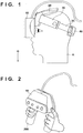
- Fig. 1 is a side view showing a video display apparatus (to be referred to as an HMD hereinafter) worn on the head of an observer according to the embodiment.
- reference numeral 10 denotes an HMD main body which incorporates an optical unit 11 (to be described later); 30, a frame for stably bringing the HMD main body 10 into tight contact with the forehead of an observer H; 35, a band member which extends from two ends of the frame 30, is formed by a flexible member (for example, a thin plate made of polypropylene or the like), and tightens the temporal region and occipital region of the observer H securely; and 20 and 40, pad members which are used to stably and comfortably fix the HMD main body 10 to the head of the observer H.
- a flexible member for example, a thin plate made of polypropylene or the like
- the handled HMD main body 10 may be considered.
- Fig. 2 is a view schematically showing the form of a handheld wearable HMD.
- the HMD main body 10 is separated from a wearing system, and connected to a handheld unit 200.
- the observer H maintains the handheld unit 200 by hands, thereby maintaining a state in which the HMD main body 10 is worn in front of the eyes of the observer H.
- the handheld type can eliminate the inconvenience of the detaching operation, and eliminate the demerit of hygiene, thereby providing an environment in which a plurality of people can use the HMD comfortably. However, both or one of the hands is not freed.
- the HMD main body 10 is worn in front of the eyes of the observer (brought into tight contact with the observer).
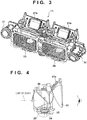
- Fig. 3 is a perspective view showing the optical unit 11 arranged in the HMD main body 10.
- Fig. 4 is a sectional view obtained by cutting the optical unit 11 on one eye side by a plane perpendicular to the optical axis of the observer.
- reference numerals 21a and 21b denote display devices which display two-dimensional videos created by an apparatus such as a PC and each of which is formed by an organic EL or a device such as a liquid crystal for displaying a video in a two-dimensional matrix. Note that each display device is not limited to the device for displaying a video in a two-dimensional matrix, and a scan-type device for displaying a video may be used, as a matter of course.
- Reference numeral 22 denotes a prism serving as a device which enlarges the video displayed on the display device 21a and forms an observation optical system for performing projection on the eyeball of the observer.
- the display device 21a and the prism 22 are arranged in front of the left eye of the observer.
- the display device 21b and a corresponding prism are arranged in front of the right eye of the observer.
- the videos displayed on the display devices 21a and 21b are enlarged through the corresponding prisms, respectively.
- the observer can obtain a high immersion feeling.
- the display devices 21a and 21b and the prism 22 function as display units for presenting images to the observer.
- Reference numerals 23 and 28 denote cameras for capturing images corresponding to the right and left fields of view of the observer.
- the camera 23 is formed from an imaging device 24 and a camera lens 25 for forming an image in the imaging device 24.
- the camera 28 has the same arrangement.
- the cameras 23 and 28 capture images each corresponding to the field of view of the observer.
- the cameras 23 and 28 will be referred to as “main cameras” hereinafter and the cameras 31 and 32 will be referred to as “sub cameras” hereinafter for the sake of convenience.
- the shooting optical axis of each of the main cameras 23 and 28 is bent once by a mirror 26 in an object direction, and changed in the lower direction, thereby entering the main camera 23 or 28.
- the optical path may be bent a plurality of times by a prism.
- the shooting optical axis of each of the main cameras 23 and 28 almost coincides with an observation optical axis on which the observer observes the prism 22, and the main camera shoots a video in the eye direction of the observer.
- each of the main cameras 23 and 28 is almost equal to or slightly wider than the angle of view when the observer observes the video on each of the display devices 21b and 21a.
- the videos shot by the main cameras 23 and 28 are connected to an external information processing apparatus such as a PC by a cable connected to the substrate of the imaging device 24 (the cable is not shown).
- the information processing apparatus generates virtual object images by CG, superimposes the generated virtual object images on the input shot images, and displays them on the display devices 21a and 21b.
- the information processing apparatus creates a virtual object to be displayed on the right and left display devices 21a and 21b.
- the observer observes the virtual object by CG created by the PC as if it existed in the physical space in front of him/her.
- the virtual object For the observer H, the virtual object must exist regardless of the position and orientation of the observer H. For example, when the observer turns right, the virtual object needs to move leftward within the field of view of the observer so that the observer observes the virtual object as if it remained at an original position. That is, the information processing apparatus needs to perform, in each of the images captured by the cameras 23 and 28, processing of superimposing the virtual object so that the position of the virtual object moves leftward. To do this, the position and orientation of the viewpoint of the observer H is detected. To detect the position and orientation of the viewpoint of the observer H, there is provided a technique of arranging a plurality of markers for detecting the position and orientation all over the physical space. The external apparatus already knows the positions and types of the markers.
- the information processing apparatus performs processing of detecting the markers in the right and left images shot by the cameras of the observer H, and detects the position and orientation of the viewpoint of the observer based on the positions and sizes of the markers in the images.
- a preset number or more of markers need to be set within the fields of view of the main cameras 23 and 28, which correspond to the field of view of the observer H.
- the observer can freely change the observation viewpoint position. Therefore, in order for markers as many as markers which can specify the position and orientation to exist in the captured images even at the worst viewpoint position, it is necessary to arrange markers within a preset interval. As a result, in some cases, many markers fall within the field of view of the observer H, thereby causing him/her to lose interest.
- this embodiment will describe an example in which while decreasing the number of markers falling within the field of view of the observer H, the position and orientation of the viewpoint of the observer can be accurately detected.
- the sub cameras 31 and 32 are arranged outside the main cameras 23 and 28 in the HMD main body 10 according to this embodiment.
- Each of the main cameras 23 and 28 captures a video of the field of view of the observer H, and has a restricted angle of view (or focal length) to obtain a video equivalent to that which the observer H actually looks at by naked eyes.
- the sub cameras 31 and 32 are cameras for detecting the position and orientation of the viewpoint of the observer H, and thus have no restrictions on the angles of view. Since the distance between the sub cameras 31 and 32 is set to be longer than that between the right and left eyes of the observer, the accuracy of parallax images is improved.
- the external apparatus acquires in advance camera parameters such as the focal lengths of the lenses and the relative positional relationships between the left and right main cameras 23 and 28 and the left and right sub cameras 31 and 32, and stores and holds them.
- the sub cameras 31 and 32 are used to calculate the position and orientation of the HMD main body 10, and have shooting angles of view wider than those of the main cameras 23 and 28. Therefore, markers for detecting the position and orientation of the HMD main body 10 exist within the fields of view of the sub cameras 31 and 32, and markers need not exist in the fields of view of the main cameras 23 and 28 in the extreme case. That is, in the same physical space, the number of markers to be arranged can be sufficiently decreased.
- the shooting angles of view of the sub cameras 31 and 32 include the angles of view of the main cameras 23 and 28.
- Fig. 5 shows an example of the shape of a marker 301 used to detect the position and orientation of the HMD main body 10.
- the marker 301 has a flat shape, and has a special geometric pattern drawn on the surface.
- images 601 to 604 shown in Fig. 6 are captured.
- the images 601 and 602 are captured by the main cameras 23 and 28, and the images 603 and 604 are captured by the sub cameras 31 and 32.
- the focal lengths and the relative relationship such as the position and orientation of the HMD main body are calculated in accordance with a known procedure based on the images captured by the sub cameras 31 and 32.
- the external apparatus Based on the calculation result, the external apparatus creates images each representing a virtual object based on CG in accordance with the calculated position and orientation, and superimposes them at corresponding positions in the images captured by the main cameras 23 and 28. As a result, even if the observer H moves around in the space, it is possible to create CG in accordance with the observation direction. The observer H can observe the virtual object based on CG as if it was fixed and existed in the physical space.
- the sub cameras 31 and 32 are used to calculate the position and orientation of the HMD main body 10, and have shooting angles of view wider than the angles of view of the main cameras 23 and 28.
- the sub cameras 31 and 32 are arranged at separated positions outside the main cameras 23 and 28. As a result, the parallax between the sub cameras 31 and 32 is larger than that between the main cameras 23 and 28, thereby making it possible to improve the position detection accuracy of the marker 301.
- Videos shot by the sub cameras 31 and 32 include videos shot by the main cameras 23 and 28.
- the sub cameras 31 and 32 are configured to shoot videos having wider angles of view.
- images shot by the sub cameras 31 and 32 include videos of the main cameras 23 and 28. Therefore, if the marker 301 is shot by the main cameras 23 and 28 for shooting the field of view of the observer H, it is ensured that the marker 301 is detected using the sub cameras 31 and 32, and it is thus possible to detect the position and orientation of the HMD main body 10.
- the sub cameras 31 and 32 include the fields of view of the main cameras 23 and 28, and are arranged to be inclined upward or downward. If, for example, the marker 301 is arranged on a ceiling or floor, the marker 301 cannot be detected using the main cameras 23 and 28 unless the HMD is made to turn in that direction, but the sub cameras 31 and 32 have shooting optical axes inclined with respect to those of the main cameras 23 and 28, and can thus detect the marker 301. Therefore, videos from the sub cameras 31 and 32 can be used to detect (or calculate) the position and orientation of the HMD main body 10.
- the observer tends to turn his/her eyes in the horizontal direction in many cases, and thus the marker itself hardly falls within the field of view of the observer H. That is, the observer need not consider the marker.
- the marker 301 is arranged on a wall, another person or object may interfere with the marker, thereby making it impossible to detect the marker.
- the angles of view of the sub cameras 31 and 32 to include those of the main cameras 23 and 28, and making the sub cameras 31 and 32 turn upward or downward by a predetermined angle, the influence of the interference of another person with the marker can be reduced.
- the eye direction of the sub camera 31 faces upward with respect to the optical axis directions of the main cameras 23 and 28, and the sub camera 32 faces downward.
- the imaging devices of the sub cameras 31 and 32 are rotated by 90° and arranged so that videos shot by the sub cameras 31 and 32 are obtained by shooting images each having a vertically-long aspect ratio. For this reason, the markers in the images 603 and 604 captured by the sub cameras 31 and 32 in Fig. 6 are rotated by 90° with respect to the markers in the images 601 and 602 captured by the main cameras 23 and 28.
- a vertically-long shooting range allows a wider range of the ceiling or floor to be shot, thereby widening the detectable range of the marker 301.
- the marker 301 arranged at a position in a direction such as the vertically upward or downward direction in which the observer H does not usually turn his/her eyes can be detected. Furthermore, the observer H can use the HMD without considering the presence of the marker 301, thereby providing a more comfortable environment.
- the marker 301 has been described as a marker obtained by drawing a geometric pattern on a flat plate.
- the shape need not be a rectangle, and various patterns may be used.
- the marker 301 need not be a flat plate, and may be three-dimensionally arranged.
- a mark such as an edge may be detected from a shot image and the position and orientation of the HMD may be calculated based on the detected edge.
- the marker is used to calculate the position and orientation of the HMD main body 10, and is not restricted in terms of the shape or the like, as a matter of course.
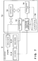
- Fig. 7 is a block diagram showing the connection relationship between the HMD main body 10 and an information processing apparatus 700, and the arrangements of the HMD main body 10 and information processing apparatus 700 according to the embodiment.
- the information processing apparatus 700 has the same hardware as that of a general PC. It is to be understood that the arrangement shown in Fig. 7 is a functional arrangement mainly based on software when an application for communicating with the HMD main body 10 is activated.
- a control unit 701 shown in Fig. 7 is formed by a CPU and a RAM storing an application to be executed by the CPU.
- a storage device 702 stores information indicating the type and arrangement position of the marker 301 in the physical space. Assume that the storage device 702 also stores information about a virtual object to be synthesized.
- the storage device 702 stores parameters such as the focal length of each camera.
- the storage device 702 is typically a hard disk device.
- the HMD main body 10 and the information processing apparatus 700 are connected by, for example, a USB (Universal Serial Bus) interface.
- a communication mode may be a wired or wireless communication mode, and any kind of interface may be used.
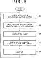
- step S1 the information processing apparatus 700 receives video data captured by the main cameras 23 and 28 and sub cameras 31 and 32 of the HMD main body 10.
- each of the main cameras 23 and 28 and the sub cameras 31 and 32 captures an image at 30 frames/sec, and outputs (transmits) the captured image as a video to the information processing apparatus 700. Therefore, it is to be understood that the processing based on the flowchart of Fig. 8 is executed every 1/30 sec.
- a position and orientation detecting unit 703 analyzes image data in the left and right videos received from the sub cameras 31 and 32.
- the position and orientation detecting unit 703 detects a preset number of markers 301 existing in the image data, and then specifies the markers and detects (calculates) the position and orientation of the HMD main body 10 based on the orientations, sizes, and the like of the markers with reference to the storage device 702. This processing is known and a detailed description thereof will be omitted.
- a CG generating unit 704 generates, based on the position and orientation of the HMD main body 10 detected by the position and orientation detecting unit 703, image data each representing a virtual object to be seen from the right and left viewpoints of the observer H.
- a CG synthesizing unit 705 synthesizes the generated image data each representing the virtual object at corresponding positions in the right and left image data captured by the main cameras 28 and 23.
- the information processing apparatus 700 transmits the synthesized right and left image data to the HMD main body 10 as video frames. As a result, the HMD main body 10 executes processing of displaying the received synthesized image data for the right and left eyes on the display devices 21a and 21b.
- the sub cameras having wider shooting fields of view including those of the main cameras for acquiring videos corresponding to the field of view of the observer are incorporated separately from the main cameras, and used to detect markers for detecting the position and orientation of the HMD main body 10. As a result, it is possible to detect the position and orientation using a smaller number of markers.
- the sub cameras can stably detect the markers by setting the sub cameras so that their fields of view include a ceiling or floor, and arranging the markers on the ceiling or floor.
- the size in the vertical direction of the field of view of each sub camera is larger than the size in the horizontal direction of the field of view, it is possible to readily detect the markers arranged on the ceiling or floor.
- the main cameras 23 and 28 capture color images and the display devices 21a and 21b display color images.
- the sub cameras 31 and 32 desirably include imaging devices for capturing monochrome images.
- R, G, and B sensors are arranged in a matrix pattern, and processing of calculating the average value of the pixel values of the adjacent components of the same type is performed at the time of demosaicing processing.
- demosaicing processing is not necessary, and a high-resolution image can be captured accordingly.
- Embodiment(s) of the present invention can also be realized by a computer of a system or apparatus that reads out and executes computer executable instructions (e.g., one or more programs) recorded on a storage medium (which may also be referred to more fully as a 'non-transitory computer-readable storage medium') to perform the functions of one or more of the above-described embodiment(s) and/or that includes one or more circuits (e.g., application specific integrated circuit (ASIC)) for performing the functions of one or more of the above-described embodiment(s), and by a method performed by the computer of the system or apparatus by, for example, reading out and executing the computer executable instructions from the storage medium to perform the functions of one or more of the above-described embodiment(s) and/or controlling the one or more circuits to perform the functions of one or more of the above-described embodiment(s).
- computer executable instructions e.g., one or more programs
- a storage medium which may also be referred to more fully as
- the computer may comprise one or more processors (e.g., central processing unit (CPU), micro processing unit (MPU)) and may include a network of separate computers or separate processors to read out and execute the computer executable instructions.
- the computer executable instructions may be provided to the computer, for example, from a network or the storage medium.
- the storage medium may include, for example, one or more of a hard disk, a random-access memory (RAM), a read only memory (ROM), a storage of distributed computing systems, an optical disk (such as a compact disc (CD), digital versatile disc (DVD), or Blu-ray Disc (BD)TM), a flash memory device, a memory card, and the like.
Applications Claiming Priority (1)
| Application Number | Priority Date | Filing Date | Title |
|---|---|---|---|
| JP2015168141A JP6641122B2 (ja) | 2015-08-27 | 2015-08-27 | 表示装置及び情報処理装置及びその制御方法 |
Publications (2)
| Publication Number | Publication Date |
|---|---|
| EP3136724A1 EP3136724A1 (en) | 2017-03-01 |
| EP3136724B1 true EP3136724B1 (en) | 2020-04-22 |
Family
ID=56567344
Family Applications (1)
| Application Number | Title | Priority Date | Filing Date |
|---|---|---|---|
| EP16001705.9A Active EP3136724B1 (en) | 2015-08-27 | 2016-08-02 | Wearable display apparatus, information processing apparatus, and control method therefor |
Country Status (3)
| Country | Link |
|---|---|
| US (1) | US20170061695A1 (ja) |
| EP (1) | EP3136724B1 (ja) |
| JP (1) | JP6641122B2 (ja) |
Families Citing this family (4)
| Publication number | Priority date | Publication date | Assignee | Title |
|---|---|---|---|---|
| US10320437B2 (en) * | 2014-10-24 | 2019-06-11 | Usens, Inc. | System and method for immersive and interactive multimedia generation |
| WO2016064435A1 (en) | 2014-10-24 | 2016-04-28 | Usens, Inc. | System and method for immersive and interactive multimedia generation |
| RU2686029C2 (ru) * | 2017-07-19 | 2019-04-23 | Автономная некоммерческая образовательная организация высшего образования "Сколковский институт науки и технологий" | Система виртуальной реальности на основе смартфона и наклонного зеркала |
| US11431952B2 (en) * | 2020-05-11 | 2022-08-30 | Sony Interactive Entertainment Inc. | User selection of virtual camera location to produce video using synthesized input from multiple cameras |
Citations (1)
| Publication number | Priority date | Publication date | Assignee | Title |
|---|---|---|---|---|
| JP2004205711A (ja) * | 2002-12-24 | 2004-07-22 | Canon Inc | 表示装置 |
Family Cites Families (14)
| Publication number | Priority date | Publication date | Assignee | Title |
|---|---|---|---|---|
| JP3387326B2 (ja) * | 1996-08-30 | 2003-03-17 | ミノルタ株式会社 | 映像観察システム |
| JP3363861B2 (ja) | 2000-01-13 | 2003-01-08 | キヤノン株式会社 | 複合現実感提示装置及び複合現実感提示方法並びに記憶媒体 |
| JP2004538538A (ja) * | 2000-10-05 | 2004-12-24 | シーメンス コーポレイト リサーチ インコーポレイテツド | 強化現実可視化付きの、手術中にイメージガイドされる神経外科手術法及び手術用装置 |
| US6891518B2 (en) * | 2000-10-05 | 2005-05-10 | Siemens Corporate Research, Inc. | Augmented reality visualization device |
| US20030227542A1 (en) * | 2001-12-20 | 2003-12-11 | Xiang Zhang | Single-computer real-time stereo augmented reality system |
| US7774044B2 (en) * | 2004-02-17 | 2010-08-10 | Siemens Medical Solutions Usa, Inc. | System and method for augmented reality navigation in a medical intervention procedure |
| JP4834424B2 (ja) * | 2006-03-03 | 2011-12-14 | キヤノン株式会社 | 情報処理装置、情報処理方法、及びプログラム |
| US9323055B2 (en) * | 2006-05-26 | 2016-04-26 | Exelis, Inc. | System and method to display maintenance and operational instructions of an apparatus using augmented reality |
| JP2008146109A (ja) * | 2006-12-05 | 2008-06-26 | Canon Inc | 画像処理方法、画像処理装置 |
| JP2011205358A (ja) | 2010-03-25 | 2011-10-13 | Fujifilm Corp | ヘッドマウントディスプレイ装置 |
| US8885877B2 (en) * | 2011-05-20 | 2014-11-11 | Eyefluence, Inc. | Systems and methods for identifying gaze tracking scene reference locations |
| JP2013174729A (ja) * | 2012-02-24 | 2013-09-05 | Nikon Corp | 情報表示装置、及び情報表示方法 |
| US10110805B2 (en) * | 2012-12-06 | 2018-10-23 | Sandisk Technologies Llc | Head mountable camera system |
| US10061349B2 (en) * | 2012-12-06 | 2018-08-28 | Sandisk Technologies Llc | Head mountable camera system |
-
2015
- 2015-08-27 JP JP2015168141A patent/JP6641122B2/ja active Active
-
2016
- 2016-08-02 EP EP16001705.9A patent/EP3136724B1/en active Active
- 2016-08-22 US US15/243,012 patent/US20170061695A1/en not_active Abandoned
Patent Citations (1)
| Publication number | Priority date | Publication date | Assignee | Title |
|---|---|---|---|---|
| JP2004205711A (ja) * | 2002-12-24 | 2004-07-22 | Canon Inc | 表示装置 |
Also Published As
| Publication number | Publication date |
|---|---|
| JP2017046233A (ja) | 2017-03-02 |
| JP6641122B2 (ja) | 2020-02-05 |
| US20170061695A1 (en) | 2017-03-02 |
| EP3136724A1 (en) | 2017-03-01 |
Similar Documents
| Publication | Publication Date | Title |
|---|---|---|
| CN106062826B (zh) | 图像生成装置以及图像生成方法 | |
| US10269139B2 (en) | Computer program, head-mounted display device, and calibration method | |
| US11184597B2 (en) | Information processing device, image generation method, and head-mounted display | |
| EP3136724B1 (en) | Wearable display apparatus, information processing apparatus, and control method therefor | |
| US20180246331A1 (en) | Helmet-mounted display, visual field calibration method thereof, and mixed reality display system | |
| CN108259883B (zh) | 图像处理方法、头戴式显示器以及可读存储介质 | |
| CN106663336B (zh) | 图像生成装置和图像生成方法 | |
| JP6855313B2 (ja) | 画像表示システム、画像表示装置および画像表示方法 | |
| US10277814B2 (en) | Display control method and system for executing the display control method | |
| TWI788739B (zh) | 3d顯示設備、3d圖像顯示方法 | |
| US20230334684A1 (en) | Scene camera retargeting | |
| US20230156176A1 (en) | Head mounted display apparatus | |
| JP4580678B2 (ja) | 注視点位置表示装置 | |
| JP2011010126A (ja) | 画像処理装置、画像処理方法 | |
| US20230239457A1 (en) | System and method for corrected video-see-through for head mounted displays | |
| US20130050427A1 (en) | Method and apparatus for capturing three-dimensional image and apparatus for displaying three-dimensional image | |
| US20180041699A1 (en) | Image display system | |
| US20150350637A1 (en) | Electronic apparatus and display processing method | |
| JP6649010B2 (ja) | 情報処理装置 | |
| JP4708590B2 (ja) | 複合現実感システム、ヘッドマウントディスプレイ装置、複合現実感実現方法及びプログラム | |
| WO2016132688A1 (en) | Information processing apparatus, information processing method, and storage medium | |
| US10679589B2 (en) | Image processing system, image processing apparatus, and program for generating anamorphic image data | |
| JP2019029721A (ja) | 画像処理装置、画像処理方法およびプログラム | |
| JP2015007722A (ja) | 画像表示装置 | |
| WO2023068087A1 (ja) | ヘッドマウントディスプレイ、情報処理装置および情報処理方法 |
Legal Events
| Date | Code | Title | Description |
|---|---|---|---|
| PUAI | Public reference made under article 153(3) epc to a published international application that has entered the european phase |
Free format text: ORIGINAL CODE: 0009012 |
|
| STAA | Information on the status of an ep patent application or granted ep patent |
Free format text: STATUS: THE APPLICATION HAS BEEN PUBLISHED |
|
| AK | Designated contracting states |
Kind code of ref document: A1 Designated state(s): AL AT BE BG CH CY CZ DE DK EE ES FI FR GB GR HR HU IE IS IT LI LT LU LV MC MK MT NL NO PL PT RO RS SE SI SK SM TR |
|
| AX | Request for extension of the european patent |
Extension state: BA ME |
|
| STAA | Information on the status of an ep patent application or granted ep patent |
Free format text: STATUS: REQUEST FOR EXAMINATION WAS MADE |
|
| 17P | Request for examination filed |
Effective date: 20170901 |
|
| RBV | Designated contracting states (corrected) |
Designated state(s): AL AT BE BG CH CY CZ DE DK EE ES FI FR GB GR HR HU IE IS IT LI LT LU LV MC MK MT NL NO PL PT RO RS SE SI SK SM TR |
|
| REG | Reference to a national code |
Ref country code: DE Ref legal event code: R079 Ref document number: 602016034336 Country of ref document: DE Free format text: PREVIOUS MAIN CLASS: H04N0013020000 Ipc: G02B0027010000 |
|
| RIC1 | Information provided on ipc code assigned before grant |
Ipc: G02B 27/01 20060101AFI20190913BHEP Ipc: H04N 13/156 20180101ALI20190913BHEP Ipc: H04N 13/239 20180101ALI20190913BHEP Ipc: H04N 13/366 20180101ALI20190913BHEP Ipc: H04N 13/279 20180101ALI20190913BHEP Ipc: H04N 13/344 20180101ALI20190913BHEP Ipc: H04N 13/383 20180101ALI20190913BHEP |
|
| GRAP | Despatch of communication of intention to grant a patent |
Free format text: ORIGINAL CODE: EPIDOSNIGR1 |
|
| STAA | Information on the status of an ep patent application or granted ep patent |
Free format text: STATUS: GRANT OF PATENT IS INTENDED |
|
| INTG | Intention to grant announced |
Effective date: 20191106 |
|
| GRAS | Grant fee paid |
Free format text: ORIGINAL CODE: EPIDOSNIGR3 |
|
| GRAA | (expected) grant |
Free format text: ORIGINAL CODE: 0009210 |
|
| STAA | Information on the status of an ep patent application or granted ep patent |
Free format text: STATUS: THE PATENT HAS BEEN GRANTED |
|
| RAP1 | Party data changed (applicant data changed or rights of an application transferred) |
Owner name: CANON KABUSHIKI KAISHA |
|
| AK | Designated contracting states |
Kind code of ref document: B1 Designated state(s): AL AT BE BG CH CY CZ DE DK EE ES FI FR GB GR HR HU IE IS IT LI LT LU LV MC MK MT NL NO PL PT RO RS SE SI SK SM TR |
|
| REG | Reference to a national code |
Ref country code: CH Ref legal event code: EP |
|
| REG | Reference to a national code |
Ref country code: IE Ref legal event code: FG4D |
|
| REG | Reference to a national code |
Ref country code: DE Ref legal event code: R096 Ref document number: 602016034336 Country of ref document: DE |
|
| REG | Reference to a national code |
Ref country code: AT Ref legal event code: REF Ref document number: 1260892 Country of ref document: AT Kind code of ref document: T Effective date: 20200515 |
|
| REG | Reference to a national code |
Ref country code: LT Ref legal event code: MG4D |
|
| REG | Reference to a national code |
Ref country code: NL Ref legal event code: MP Effective date: 20200422 |
|
| PG25 | Lapsed in a contracting state [announced via postgrant information from national office to epo] |
Ref country code: PT Free format text: LAPSE BECAUSE OF FAILURE TO SUBMIT A TRANSLATION OF THE DESCRIPTION OR TO PAY THE FEE WITHIN THE PRESCRIBED TIME-LIMIT Effective date: 20200824 Ref country code: SE Free format text: LAPSE BECAUSE OF FAILURE TO SUBMIT A TRANSLATION OF THE DESCRIPTION OR TO PAY THE FEE WITHIN THE PRESCRIBED TIME-LIMIT Effective date: 20200422 Ref country code: NL Free format text: LAPSE BECAUSE OF FAILURE TO SUBMIT A TRANSLATION OF THE DESCRIPTION OR TO PAY THE FEE WITHIN THE PRESCRIBED TIME-LIMIT Effective date: 20200422 Ref country code: LT Free format text: LAPSE BECAUSE OF FAILURE TO SUBMIT A TRANSLATION OF THE DESCRIPTION OR TO PAY THE FEE WITHIN THE PRESCRIBED TIME-LIMIT Effective date: 20200422 Ref country code: GR Free format text: LAPSE BECAUSE OF FAILURE TO SUBMIT A TRANSLATION OF THE DESCRIPTION OR TO PAY THE FEE WITHIN THE PRESCRIBED TIME-LIMIT Effective date: 20200723 Ref country code: NO Free format text: LAPSE BECAUSE OF FAILURE TO SUBMIT A TRANSLATION OF THE DESCRIPTION OR TO PAY THE FEE WITHIN THE PRESCRIBED TIME-LIMIT Effective date: 20200722 Ref country code: IS Free format text: LAPSE BECAUSE OF FAILURE TO SUBMIT A TRANSLATION OF THE DESCRIPTION OR TO PAY THE FEE WITHIN THE PRESCRIBED TIME-LIMIT Effective date: 20200822 Ref country code: FI Free format text: LAPSE BECAUSE OF FAILURE TO SUBMIT A TRANSLATION OF THE DESCRIPTION OR TO PAY THE FEE WITHIN THE PRESCRIBED TIME-LIMIT Effective date: 20200422 |
|
| REG | Reference to a national code |
Ref country code: AT Ref legal event code: MK05 Ref document number: 1260892 Country of ref document: AT Kind code of ref document: T Effective date: 20200422 |
|
| PG25 | Lapsed in a contracting state [announced via postgrant information from national office to epo] |
Ref country code: LV Free format text: LAPSE BECAUSE OF FAILURE TO SUBMIT A TRANSLATION OF THE DESCRIPTION OR TO PAY THE FEE WITHIN THE PRESCRIBED TIME-LIMIT Effective date: 20200422 Ref country code: RS Free format text: LAPSE BECAUSE OF FAILURE TO SUBMIT A TRANSLATION OF THE DESCRIPTION OR TO PAY THE FEE WITHIN THE PRESCRIBED TIME-LIMIT Effective date: 20200422 Ref country code: HR Free format text: LAPSE BECAUSE OF FAILURE TO SUBMIT A TRANSLATION OF THE DESCRIPTION OR TO PAY THE FEE WITHIN THE PRESCRIBED TIME-LIMIT Effective date: 20200422 Ref country code: BG Free format text: LAPSE BECAUSE OF FAILURE TO SUBMIT A TRANSLATION OF THE DESCRIPTION OR TO PAY THE FEE WITHIN THE PRESCRIBED TIME-LIMIT Effective date: 20200722 |
|
| PG25 | Lapsed in a contracting state [announced via postgrant information from national office to epo] |
Ref country code: AL Free format text: LAPSE BECAUSE OF FAILURE TO SUBMIT A TRANSLATION OF THE DESCRIPTION OR TO PAY THE FEE WITHIN THE PRESCRIBED TIME-LIMIT Effective date: 20200422 |
|
| REG | Reference to a national code |
Ref country code: DE Ref legal event code: R097 Ref document number: 602016034336 Country of ref document: DE |
|
| PG25 | Lapsed in a contracting state [announced via postgrant information from national office to epo] |
Ref country code: CZ Free format text: LAPSE BECAUSE OF FAILURE TO SUBMIT A TRANSLATION OF THE DESCRIPTION OR TO PAY THE FEE WITHIN THE PRESCRIBED TIME-LIMIT Effective date: 20200422 Ref country code: IT Free format text: LAPSE BECAUSE OF FAILURE TO SUBMIT A TRANSLATION OF THE DESCRIPTION OR TO PAY THE FEE WITHIN THE PRESCRIBED TIME-LIMIT Effective date: 20200422 Ref country code: EE Free format text: LAPSE BECAUSE OF FAILURE TO SUBMIT A TRANSLATION OF THE DESCRIPTION OR TO PAY THE FEE WITHIN THE PRESCRIBED TIME-LIMIT Effective date: 20200422 Ref country code: DK Free format text: LAPSE BECAUSE OF FAILURE TO SUBMIT A TRANSLATION OF THE DESCRIPTION OR TO PAY THE FEE WITHIN THE PRESCRIBED TIME-LIMIT Effective date: 20200422 Ref country code: ES Free format text: LAPSE BECAUSE OF FAILURE TO SUBMIT A TRANSLATION OF THE DESCRIPTION OR TO PAY THE FEE WITHIN THE PRESCRIBED TIME-LIMIT Effective date: 20200422 Ref country code: RO Free format text: LAPSE BECAUSE OF FAILURE TO SUBMIT A TRANSLATION OF THE DESCRIPTION OR TO PAY THE FEE WITHIN THE PRESCRIBED TIME-LIMIT Effective date: 20200422 Ref country code: SM Free format text: LAPSE BECAUSE OF FAILURE TO SUBMIT A TRANSLATION OF THE DESCRIPTION OR TO PAY THE FEE WITHIN THE PRESCRIBED TIME-LIMIT Effective date: 20200422 Ref country code: AT Free format text: LAPSE BECAUSE OF FAILURE TO SUBMIT A TRANSLATION OF THE DESCRIPTION OR TO PAY THE FEE WITHIN THE PRESCRIBED TIME-LIMIT Effective date: 20200422 |
|
| PG25 | Lapsed in a contracting state [announced via postgrant information from national office to epo] |
Ref country code: PL Free format text: LAPSE BECAUSE OF FAILURE TO SUBMIT A TRANSLATION OF THE DESCRIPTION OR TO PAY THE FEE WITHIN THE PRESCRIBED TIME-LIMIT Effective date: 20200422 Ref country code: SK Free format text: LAPSE BECAUSE OF FAILURE TO SUBMIT A TRANSLATION OF THE DESCRIPTION OR TO PAY THE FEE WITHIN THE PRESCRIBED TIME-LIMIT Effective date: 20200422 |
|
| PLBE | No opposition filed within time limit |
Free format text: ORIGINAL CODE: 0009261 |
|
| STAA | Information on the status of an ep patent application or granted ep patent |
Free format text: STATUS: NO OPPOSITION FILED WITHIN TIME LIMIT |
|
| REG | Reference to a national code |
Ref country code: DE Ref legal event code: R119 Ref document number: 602016034336 Country of ref document: DE |
|
| 26N | No opposition filed |
Effective date: 20210125 |
|
| PG25 | Lapsed in a contracting state [announced via postgrant information from national office to epo] |
Ref country code: MC Free format text: LAPSE BECAUSE OF FAILURE TO SUBMIT A TRANSLATION OF THE DESCRIPTION OR TO PAY THE FEE WITHIN THE PRESCRIBED TIME-LIMIT Effective date: 20200422 |
|
| REG | Reference to a national code |
Ref country code: CH Ref legal event code: PL |
|
| PG25 | Lapsed in a contracting state [announced via postgrant information from national office to epo] |
Ref country code: CH Free format text: LAPSE BECAUSE OF NON-PAYMENT OF DUE FEES Effective date: 20200831 Ref country code: LU Free format text: LAPSE BECAUSE OF NON-PAYMENT OF DUE FEES Effective date: 20200802 Ref country code: LI Free format text: LAPSE BECAUSE OF NON-PAYMENT OF DUE FEES Effective date: 20200831 |
|
| REG | Reference to a national code |
Ref country code: BE Ref legal event code: MM Effective date: 20200831 |
|
| PG25 | Lapsed in a contracting state [announced via postgrant information from national office to epo] |
Ref country code: SI Free format text: LAPSE BECAUSE OF FAILURE TO SUBMIT A TRANSLATION OF THE DESCRIPTION OR TO PAY THE FEE WITHIN THE PRESCRIBED TIME-LIMIT Effective date: 20200422 |
|
| PG25 | Lapsed in a contracting state [announced via postgrant information from national office to epo] |
Ref country code: DE Free format text: LAPSE BECAUSE OF NON-PAYMENT OF DUE FEES Effective date: 20210302 Ref country code: FR Free format text: LAPSE BECAUSE OF NON-PAYMENT OF DUE FEES Effective date: 20200831 |
|
| PG25 | Lapsed in a contracting state [announced via postgrant information from national office to epo] |
Ref country code: BE Free format text: LAPSE BECAUSE OF NON-PAYMENT OF DUE FEES Effective date: 20200831 Ref country code: IE Free format text: LAPSE BECAUSE OF NON-PAYMENT OF DUE FEES Effective date: 20200802 |
|
| PG25 | Lapsed in a contracting state [announced via postgrant information from national office to epo] |
Ref country code: TR Free format text: LAPSE BECAUSE OF FAILURE TO SUBMIT A TRANSLATION OF THE DESCRIPTION OR TO PAY THE FEE WITHIN THE PRESCRIBED TIME-LIMIT Effective date: 20200422 Ref country code: MT Free format text: LAPSE BECAUSE OF FAILURE TO SUBMIT A TRANSLATION OF THE DESCRIPTION OR TO PAY THE FEE WITHIN THE PRESCRIBED TIME-LIMIT Effective date: 20200422 Ref country code: CY Free format text: LAPSE BECAUSE OF FAILURE TO SUBMIT A TRANSLATION OF THE DESCRIPTION OR TO PAY THE FEE WITHIN THE PRESCRIBED TIME-LIMIT Effective date: 20200422 |
|
| PG25 | Lapsed in a contracting state [announced via postgrant information from national office to epo] |
Ref country code: MK Free format text: LAPSE BECAUSE OF FAILURE TO SUBMIT A TRANSLATION OF THE DESCRIPTION OR TO PAY THE FEE WITHIN THE PRESCRIBED TIME-LIMIT Effective date: 20200422 |
|
| PGFP | Annual fee paid to national office [announced via postgrant information from national office to epo] |
Ref country code: GB Payment date: 20230720 Year of fee payment: 8 |