EP3136641A1 - Verfahren und endgerät zur übertragung eines klangreferenzsignals in einem drahtloskommunikationssystem - Google Patents
Verfahren und endgerät zur übertragung eines klangreferenzsignals in einem drahtloskommunikationssystem Download PDFInfo
- Publication number
- EP3136641A1 EP3136641A1 EP15782272.7A EP15782272A EP3136641A1 EP 3136641 A1 EP3136641 A1 EP 3136641A1 EP 15782272 A EP15782272 A EP 15782272A EP 3136641 A1 EP3136641 A1 EP 3136641A1
- Authority
- EP
- European Patent Office
- Prior art keywords
- srs
- pucch
- transmitted
- terminal
- subframe
- Prior art date
- Legal status (The legal status is an assumption and is not a legal conclusion. Google has not performed a legal analysis and makes no representation as to the accuracy of the status listed.)
- Granted
Links
Images


Classifications
-
- H—ELECTRICITY
- H04—ELECTRIC COMMUNICATION TECHNIQUE
- H04L—TRANSMISSION OF DIGITAL INFORMATION, e.g. TELEGRAPHIC COMMUNICATION
- H04L5/00—Arrangements affording multiple use of the transmission path
- H04L5/003—Arrangements for allocating sub-channels of the transmission path
- H04L5/0048—Allocation of pilot signals, i.e. of signals known to the receiver
- H04L5/0051—Allocation of pilot signals, i.e. of signals known to the receiver of dedicated pilots, i.e. pilots destined for a single user or terminal
-
- H—ELECTRICITY
- H04—ELECTRIC COMMUNICATION TECHNIQUE
- H04L—TRANSMISSION OF DIGITAL INFORMATION, e.g. TELEGRAPHIC COMMUNICATION
- H04L27/00—Modulated-carrier systems
- H04L27/26—Systems using multi-frequency codes
- H04L27/2601—Multicarrier modulation systems
- H04L27/2602—Signal structure
- H04L27/261—Details of reference signals
- H04L27/2613—Structure of the reference signals
-
- H—ELECTRICITY
- H04—ELECTRIC COMMUNICATION TECHNIQUE
- H04L—TRANSMISSION OF DIGITAL INFORMATION, e.g. TELEGRAPHIC COMMUNICATION
- H04L5/00—Arrangements affording multiple use of the transmission path
-
- H—ELECTRICITY
- H04—ELECTRIC COMMUNICATION TECHNIQUE
- H04L—TRANSMISSION OF DIGITAL INFORMATION, e.g. TELEGRAPHIC COMMUNICATION
- H04L5/00—Arrangements affording multiple use of the transmission path
- H04L5/0001—Arrangements for dividing the transmission path
- H04L5/0014—Three-dimensional division
- H04L5/0016—Time-frequency-code
-
- H—ELECTRICITY
- H04—ELECTRIC COMMUNICATION TECHNIQUE
- H04L—TRANSMISSION OF DIGITAL INFORMATION, e.g. TELEGRAPHIC COMMUNICATION
- H04L5/00—Arrangements affording multiple use of the transmission path
- H04L5/003—Arrangements for allocating sub-channels of the transmission path
- H04L5/0053—Allocation of signalling, i.e. of overhead other than pilot signals
-
- H—ELECTRICITY
- H04—ELECTRIC COMMUNICATION TECHNIQUE
- H04W—WIRELESS COMMUNICATION NETWORKS
- H04W72/00—Local resource management
- H04W72/20—Control channels or signalling for resource management
- H04W72/21—Control channels or signalling for resource management in the uplink direction of a wireless link, i.e. towards the network
-
- H—ELECTRICITY
- H04—ELECTRIC COMMUNICATION TECHNIQUE
- H04W—WIRELESS COMMUNICATION NETWORKS
- H04W72/00—Local resource management
- H04W72/20—Control channels or signalling for resource management
- H04W72/23—Control channels or signalling for resource management in the downlink direction of a wireless link, i.e. towards a terminal
Definitions
- the present invention relates to mobile communication..
- 3GPP LTE long term evolution (LTE) evolved from a universal mobile telecommunications system (UMTS) is introduced as the 3GPP release 8.
- 3GPP LTE uses orthogonal frequency division multiple access (OFDMA) in a downlink, and uses single carrier-frequency division multiple access (SC-FDMA) in an uplink.
- OFDMA orthogonal frequency division multiple access
- SC-FDMA single carrier-frequency division multiple access
- MIMO multiple input multiple output
- LTE-A 3GPP LTE-advanced
- 3GPP LTE/LTE-A may divide the physical channel into a downlink channel, i.e., a physical downlink shared channel (PDSCH) and a physical downlink control channel (PDCCH), and an uplink channel, i.e., a physical uplink shared channel (PUSCH) and a physical uplink control channel (PUCCH).
- a downlink channel i.e., a physical downlink shared channel (PDSCH) and a physical downlink control channel (PDCCH)
- PUCCH physical downlink control channel
- PUSCH physical uplink shared channel
- PUCCH physical uplink control channel
- an uplink channel or a downlink channel needs to be estimated for transmission/reception of data, system synchronization acquisition, channel information feedback, and the like.
- fading occurs due to a multi-path time delay.
- a process of restoring a transmission signal by compensating distortion of a signal, which occurs by a rapid environmental change due to the fading is referred to channel estimation.
- a channel state for a cell to which a terminal belongs or another cell needs to be measured.
- the channel estimation is generally performed by using a reference signal (RS) which a transmitter and a receiver mutually know.
- RS reference signal
- An uplink reference signal may be divided into a demodulation reference signal (DMRS) and a sounding reference signal (SRS).
- the DMRS is a reference signal used in the channel estimation for demodulating a received signal.
- the DMRS may be associated with transmission of a PUSCH or PUCCH.
- the SRS is a reference signal which the terminal transmits to a base station for uplink scheduling.
- the base station estimates an uplink channel through the received SRS and uses the estimated uplink channel in the uplink scheduling.
- the SRS may be periodically transmitted or when the base station needs to transmit the SRS, the SRS is triggered by the base station to be aperiodically transmitted.
- the sounding reference signal is not generally transmitted on a transmission region (alternatively, a resource region for the PUCCH) for the PUCCH.
- a situation may be considered, in which the PUCCH is transmitted in a secondary cell (SCell) for the purpose of offloading for the PUCCH even with respect to a cell or a cell group having the same geographical position in a next system.
- SCell secondary cell
- a transmission method of the sounding reference signal through a PUCCH region may be required for more efficient uplink scheduling.
- a method for transmitting a sound reference signal (SRS) in a wireless communication system may be performed by a terminal and may include: receiving, by the terminal an SRS configuration from a base station; determining an SRS subframe on which the SRS is to be transmitted among a plurality of subframes and an SRS transmission region on which the SRS is to be transmitted in a physical uplink control channel (PUCCH) region on the SRS subframe, on the basis of the received SRS configuration; and transmitting the SRS in the SRS transmission region on the determined SRS subframe, wherein when the SRS and a PUCCH are simultaneously transmitted in the SRS transmission region, the SRS and the PUCCH may be multiplexed on the basis of code division multiplexing (CDM).
- CDM code division multiplexing
- the multiplexing may be based on an orthogonal cover code (OCC).
- OCC orthogonal cover code
- the SRS subframe may include two slots including a plurality of orthogonal frequency division multiplexing (OFDM) symbols, and the SRS may be transmitted in the last OFDM symbol of each of the two slots.
- OFDM orthogonal frequency division multiplexing
- the SRS may be transmitted to be symmetric based on the center of an uplink bandwidth.
- the SRS subframe may include two slots including the plurality of orthogonal frequency division multiplexing (OFDM) symbols, and the SRS may be transmitted in any one OFDM symbol of each of the two slots.
- OFDM orthogonal frequency division multiplexing
- the any one OFDM symbol may be designated in the SRS configuration or predesignated according to a radio network temporary identifier (RNTI) of the terminal.
- RNTI radio network temporary identifier
- the SRS subframe may include two slots including the plurality of orthogonal frequency division multiplexing (OFDM) symbols, and the SRS may be transmitted in OFDM symbols corresponding to all or some of DMRSs among the plurality of OFDM symbols.
- OFDM orthogonal frequency division multiplexing
- the SRS may be transmitted based on PUCC format 3.
- the SRS may be transmitted onto a PUCCH resource allocated based on a UL grant.
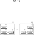
- a terminal for transmitting a sound reference signal (SRS) in a wireless communication system may include: an RF unit configured to receiv an SRS configuration from a base station; and a processor configured to control the RF unit to determine an SRS subframe on which the SRS is to be transmitted among a plurality of subframes and an SRS transmission region on which the SRS is to be transmitted in a physical uplink control channel (PUCCH) region on the SRS subframe, on the basis of the received SRS configuration and transmit the SRS in the SRS transmission region on the determined SRS subframe, wherein when the SRS and a PUCCH are simultaneously transmitted in the SRS transmission region, the SRS and the PUCCH may be multiplexed on the basis of code division multiplexing (CDM).
- CDM code division multiplexing
- the problem in the related art is solved.
- efficient transmission of a sounding reference signal through a PUCCH region is enabled.
- LTE long term evolution
- LTE-A 3rd Generation Partnership Project LTE-advanced
- the term 'include' or 'have' may represent the existence of a feature, a number, a step, an operation, a component, a part or the combination thereof described in the present invention, and may not exclude the existence or addition of another feature, another number, another step, another operation, another component, another part or the combination thereof.
- first' and 'second' are used for the purpose of explanation about various components, and the components are not limited to the terms 'first' and 'second'.
- the terms 'first' and 'second' are only used to distinguish one component from another component.
- a first component may be named as a second component without deviating from the scope of the present invention.
- 'base station' generally refers to a fixed station that communicates with a wireless device and may be denoted by other terms such as eNB (evolved-NodeB), BTS (base transceiver system), or access point.
- eNB evolved-NodeB
- BTS base transceiver system
- 'user equipment may be stationary or mobile, and may be denoted by other terms such as device, wireless device, terminal, MS (mobile station), UT (user terminal), SS (subscriber station), MT (mobile terminal) and etc.
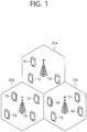
- FIG. 1 illustrates a wireless communication system
- the wireless communication system includes at least one base station (BS) 20.
- Each base station 20 provides a communication service to specific geographical areas (generally, referred to as cells) 20a, 20b, and 20c.
- the cell can be further divided into a plurality of areas (sectors).
- the UE generally belongs to one cell and the cell to which the UE belong is referred to as a serving cell.
- a base station that provides the communication service to the serving cell is referred to as a serving BS. Since the wireless communication system is a cellular system, another cell that neighbors to the serving cell is present. Another cell which neighbors to the serving cell is referred to a neighbor cell.
- a base station that provides the communication service to the neighbor cell is referred to as a neighbor BS.
- the serving cell and the neighbor cell are relatively decided based on the UE.
- a downlink means communication from the base station 20 to the UE1 10 and an uplink means communication from the UE 10 to the base station 20.
- a transmitter may be a part of the base station 20 and a receiver may be a part of the UE 10.
- the transmitter may be a part of the UE 10 and the receiver may be a part of the base station 20.
- the wireless communication system may be generally divided into a frequency division duplex (FDD) type and a time division duplex (TDD) type.
- FDD frequency division duplex
- TDD time division duplex
- uplink transmission and downlink transmission are achieved while occupying different frequency bands.
- the uplink transmission and the downlink transmission are achieved at different time while occupying the same frequency band.
- a channel response of the TDD type is substantially reciprocal. This means that a downlink channel response and an uplink channel response are approximately the same as each other in a given frequency area. Accordingly, in the TDD based wireless communication system, the downlink channel response may be acquired from the uplink channel response.
- the downlink transmission by the base station and the uplink transmission by the terminal may not be performed simultaneously.
- the uplink transmission and the downlink transmission are performed in different subframes.
- FIG. 2 illustrates a structure of a radio frame according to FDD of 3rd generation partnership project (3GPP) long term evolution (LTE).
- 3GPP 3rd generation partnership project
- LTE long term evolution
- the radio frame of FIG. 2 may be found in the section 5 of 3GPP TS 36.211 V10.4.0 (2011-12) "Evolved Universal Terrestrial Radio Access (E-UTRA); Physical Channels and Modulation (Release 10) ".
- the radio frame includes 10 subframes indexed 0 to 9.
- One subframe includes two consecutive slots. Accordingly, the radio frame includes 20 slots.
- the time taken for one subframe to be transmitted is denoted TTI (transmission time interval).
- TTI transmission time interval
- the length of one subframe may be 1ms
- the length of one slot may be 0.5ms.
- the structure of the radio frame is for exemplary purposes only, and thus the number of subframes included in the radio frame or the number of slots included in the subframe may change variously.
- one slot may include a plurality of OFDM symbols.
- the number of OFDM symbols included in one slot may vary depending on a cyclic prefix (CP).
- CP cyclic prefix
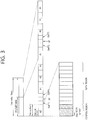
- FIG. 3 illustrates a structure of a downlink radio frame according to TDD in 3GPP LTE.
- Subframes having index #1 and index #6 are denoted special subframes, and include a DwPTS(Downlink Pilot Time Slot: DwPTS), a GP(Guard Period) and an UpPTS(Uplink Pilot Time Slot).
- the DwPTS is used for initial cell search, synchronization, or channel estimation in a terminal.
- the UpPTS is used for channel estimation in the base station and for establishing uplink transmission sync of the terminal.
- the GP is a period for removing interference that arises on uplink due to a multi-path delay of a downlink signal between uplink and downlink.
- Table 1 shows an example of configuration of a radio frame.
- 'D' denotes a DL subframe, 'U' a UL subframe, and 'S' a special subframe.
- the terminal may be aware of whether a subframe is a DL subframe or a UL subframe according to the configuration of the radio frame.
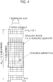
- FIG. 4 illustrates an example of a resource grid for one uplink or downlink slot in 3GPP LTE.
- the uplink slot includes a plurality of OFDM (orthogonal frequency division multiplexing) symbols in the time domain and NRB resource blocks (RBs) in the frequency domain.
- RBs resource blocks
- the number of resource blocks (RBs), i.e., NRB may be one from 6 to 110.
- the resource block is a unit of resource allocation and includes a plurality of sub-carriers in the frequency domain. For example, if one slot includes seven OFDM symbols in the time domain and the resource block includes 12 sub-carriers in the frequency domain, one resource block may include 7x12 resource elements (REs).
- REs resource elements
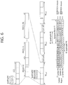
- FIG. 5 illustrates a sturcture of a downlink subframe.
- one slot includes seven OFDM symbols, by way of example.
- the DL (downlink) subframe is split into a control region and a data region in the time domain.
- the control region includes up to first three OFDM symbols in the first slot of the subframe. However, the number of OFDM symbols included in the control region may be changed.
- a PDCCH (physical downlink control channel) and other control channels are assigned to the control region, and a PDSCH is assigned to the data region.
- the physical channels in 3GPP LTE may be classified into data channels such as PDSCH (physical downlink shared channel) and PUSCH (physical uplink shared channel) and control channels such as PDCCH (physical downlink control channel), PCFICH (physical control format indicator channel), PHICH (physical hybrid-ARQ indicator channel) and PUCCH (physical uplink control channel).
- data channels such as PDSCH (physical downlink shared channel) and PUSCH (physical uplink shared channel) and control channels
- PDCCH physical downlink control channel
- PCFICH physical control format indicator channel
- PHICH physical hybrid-ARQ indicator channel
- PUCCH physical uplink control channel
- the PCFICH transmitted in the first OFDM symbol of the subframe carries CIF (control format indicator) regarding the number (i.e., size of the control region) of OFDM symbols used for transmission of control channels in the subframe.
- the wireless device first receives the CIF on the PCFICH and then monitors the PDCCH.
- the PCFICH is transmitted through a fixed PCFICH resource in the subframe without using blind decoding.
- the PHICH carries an ACK (positive-acknowledgement)/NACK (negative-acknowledgement) signal for a UL HARQ (hybrid automatic repeat request).
- the ACK/NACK signal for UL (uplink) data on the PUSCH transmitted by the wireless device is sent on the PHICH.
- the PBCH (physical broadcast channel) is transmitted in the first four OFDM symbols in the second slot of the first subframe of the radio frame.
- the PBCH carries system information necessary for the wireless device to communicate with the base station, and the system information transmitted through the PBCH is denoted MIB (master information block).
- MIB master information block
- SIB system information block
- the PDCCH may carry activation of VoIP (voice over internet protocol) and a set of transmission power control commands for individual UEs in some UE group, resource allocation of an upper layer control message such as a random access response transmitted on the PDSCH, system information on DL-SCH, paging information on PCH, resource allocation information of UL-SCH (uplink shared channel), and resource allocation and transmission format of DL-SCH (downlink-shared channel).
- a plurality of PDCCHs may be sent in the control region, and the terminal may monitor the plurality of PDCCHs.
- the PDCCH is transmitted on one CCE (control channel element) or aggregation of some consecutive CCEs.
- the CCE is a logical allocation unit used for providing a coding rate per radio channel's state to the PDCCH.
- the CCE corresponds to a plurality of resource element groups. Depending on the relationship between the number of CCEs and coding rates provided by the CCEs, the format of the PDCCH and the possible number of PDCCHs are determined.
- the control information transmitted through the PDCCH is denoted downlink control information (DCI).
- DCI may include resource allocation of PDSCH (this is also referred to as DL (downlink) grant), resource allocation of PUSCH (this is also referred to as UL (uplink) grant), a set of transmission power control commands for individual UEs in some UE group, and/or activation of VoIP (Voice over Internet Protocol).
- the base station determines a PDCCH format according to the DCI to be sent to the terminal and adds a CRC (cyclic redundancy check) to control information.
- the CRC is masked with a unique identifier (RNTI; radio network temporary identifier) depending on the owner or purpose of the PDCCH.
- RNTI unique identifier
- the terminal's unique identifier such as C-RNTI (cell-RNTI)
- a paging indicator for example, P-RNTI (paging-RNTI) may be masked to the CRC.
- SI-RNTI system information-RNTI
- RA-RNTI random access-RNTI
- blind decoding is used for detecting a PDCCH.
- the blind decoding is a mode of identifying whether a PDCCH is its own control channel by demasking a desired identifier to the CRC (cyclic redundancy check) of a received PDCCH (this is referred to as candidate PDCCH) and checking a CRC error.
- the base station determines a PDCCH format according to the DCI to be sent to the wireless device, then adds a CRC to the DCI, and masks a unique identifier (this is referred to as RNTI (radio network temporary identifier) to the CRC depending on the owner or purpose of the PDCCH.
- RNTI radio network temporary identifier
- FIG. 6 illustrates an example of resource mapping of a PDCCH.
- R0 denotes a reference signal of a 1 st antenna
- R1 denotes a reference signal of a 2 nd antenna
- R2 denotes a reference signal of a 3 rd antenna
- R3 denotes a reference signal of a 4 th antenna.
- a control region in a subframe includes a plurality of control channel elements (CCEs).
- the CCE is a logical allocation unit used to provide the PDCCH with a coding rate depending on a state of a radio channel, and corresponds to a plurality of resource element groups (REGs).
- the REG includes a plurality of resource elements (REs). According to the relationship between the number of CCEs and the coding rate provided by the CCEs, a PDCCH format and a possible PDCCH bit number are determined.
- a BS determines the number of CCEs used in transmission of the PDCCH according to a channel state. For example, a UE having a good DL channel state may use one CCE in PDCCH transmission. A UE having a poor DL channel state may use 8 CCEs in PDCCH transmission.
- One REG (indicated by a quadruplet in the drawing) includes 4 REs.
- One CCE includes 9 REGs.
- the number of CCEs used to configure one PDCCH may be selected from ⁇ 1, 2, 4, 8 ⁇ . Each element of ⁇ 1, 2, 4, 8 ⁇ is referred to as a CCE aggregation level.
- a control channel consisting of one or more CCEs performs interleaving in unit of REG, and is mapped to a physical resource after performing cyclic shift based on a cell identifier (ID).
- ID cell identifier
- FIG. 7 illustrates an example of monitoring of a PDCCH.
- a UE cannot know about a specific position in a control region in which its PDCCH is transmitted and about a specific CCE aggregation or DCI format used for transmission.
- a plurality of PDCCHs can be transmitted in one subframe, and thus the UE monitors the plurality of PDCCHs in every subframe.
- monitoring is an operation of attempting PDCCH decoding by the UE according to a PDCCH format.
- the 3GPP LTE uses a search space to reduce an overhead of blind decoding.
- the search space can also be called a monitoring set of a CCE for the PDCCH.
- the UE monitors the PDCCH in the search space.
- the search space is classified into a common search space and a UE-specific search space.
- the common search space is a space for searching for a PDCCH having common control information and consists of 16 CCEs indexed with 0 to 15.
- the common search space supports a PDCCH having a CCE aggregation level of ⁇ 4, 8 ⁇ .
- a PDCCH e.g., DCI formats 0, 1A
- the UE-specific search space supports a PDCCH having a CCE aggregation level of ⁇ 1, 2, 4, 8 ⁇ .
- Table 2 shows the number of PDCCH candidates monitored by a wireless device.
- Search space S (L) k Number M (L) of PDCCH candidates
- Type Aggregation level L Size [in CCEs] UE-specific 1 6 6 2 12 6 4 8 2 8 16 2 Commo n 4 16 4 8 16 2
- a size of the search space is determined by Table 2 above, and a start point of the search space is defined differently in the common search space and the UE-specific search space.
- a start point of the common search space is fixed irrespective of a subframe, a start point of the UE-specific search space may vary in every subframe according to a UE identifier (e.g., C-RNTI), a CCE aggregation level, and/or a slot number in a radio frame. If the start point of the UE-specific search space exists in the common search space, the UE-specific search space and the common search space may overlap with each other.
- a search space S (L) k is defined as a set of PDCCH candidates.
- a CCE corresponding to a PDCCH candidate m of the search space S (L) k is given by Equation 1 below.
- N CCE,k denotes the total number of CCEs that can be used for PDCCH transmission in a control region of a subframe k.
- the control region includes a set of CCEs numbered from 0 to N CCE,k -1.
- M (L) denotes the number of PDCCH candidates in a CCE aggregation level L of a given search space.
- a variable Y k is defined by below.
- Y k A ⁇ Y k ⁇ 1 mod D
- a search space and a DCI format used in monitoring are determined according to a transmission mode of the PDSCH.
- a search space and a DCI format used in monitoring are determined according to a transmission mode (TM) of the PDSCH.
- Table 3 shows an example of PDCCH monitoring for which the C-RNTI is configured.
- Transmission mode DCI format Search space Transmission mode of PDSCH according to PDCCH Transmission mode 1 DCI format 1A Public service and terminal specific Single antenna port, port 0 DCI format 1 Terminal specific Single antenna port, port 0 Transmission mode 2 DCI format 1A Public service and terminal specific Transmit diversity DCI format 1 Terminal specific Transmit diversity Transmission mode 3 DCI format 1A Public service and terminal specific Transmit diversity DCI format 2A Terminal specific CDD(Cyclic Delay Diversity) or transmit diversity Transmission mode 4 DCI format 1A Public service and terminal specific Transmit diversity DCI format 2 Terminal specific Closed-loop spatial multiplexing Transmission mode 5 DCI format 1A Public service and terminal specific Transmit diversity DCI format 1D Terminal specific MU-MIMO(Multi-user Multiple Input Multiple Output) Transmission mode 6 DCI format 1A Public service and terminal specific Transmit diversity DCI format 1B Terminal specific Closed-loop spatial multiplexing Transmission mode 7 DCI format 1A Public service and terminal specific If the number of PBCH transmisison ports is 1, single antenna port, port 0.
- transmit diversity DCI format 1 Terminal specific Single antenna port, port 5 Transmission mode 8 DCI format 1A Public service and terminal specific If the number of PBCH transmisison ports is 1, single antenna port, port 0. Otherwise, transmit diversity DCI format 2B Terminal specific Dual layer transmisison (port 7 or 8), or single antenna port, port 7 or 8 Transmission mode 9 DCI format 1 A Public service and terminal specific Non-MBSFN sub-frame: if the number of PBCH antenna ports is 1, port 0 is used as independent antenna port.
- transmit Diversity MBSFN sub-frame port 7 as independent antenna port DCI format 2C Terminal specific 8 transmisison layers, ports 7-14 are used or port 7 or 8 is used as independent antenna port Transmission mode 10 DCI 1A Public service and terminal specific Non-MBSFN sub-frame: if then number of PBCH antenna ports is 1, port 0 is used as independent antenna port. Otherwise, transmit Diversity MBSFN sub-frame: port 7 as independent antenna port DCI format 2D Terminal specific 8 transmisison layers, ports 7-14 are used or port 7 or 8 is used as independent antenna port
- DCI format Contents DCI format 0 Used in PUSCH scheduling DCI format 1 Used in scheduling of one PDSCH codeword DCI format 1A Used in compact scheduling of one PDSCH codeword and random access process DCI format 1B Used in compact scheduling of one PDSCH codeword having precoding information DCI format 1C Used in very compact scheduling of one PDSCH codeword DCI format 1D Used in precoding and compact scheduling of one PDSCH codeword having power offset information DCI format 2 Used in PDSCH scheduling of terminals configured in closed-loop spatial multiplexing mode DCI format 2A Used in PDSCH scheduling of terminals configured in open-loop spatial multiplexing mode DCI format 2B DCI format 2B is used for resouce allocation for dual-layer beamforming of PDSCH.
- DCI format 2C DCI format 2C is used for resouce allocation for closed-loop SU-MIMO or MU-MIMO operation to 8 layers.
- DCI format 2D DCI format 2C is used for resouce allocation to 8 layers.
- DCI format 3 Used to transmit TPC command of PUCCH and PUSCH having 2 bit power adjustments
- DCI format 3A Used to transmit TPC command of PUCCH and PUSCH having 1 bit power adjustment
- DCI format 4 Used in PUSCH scheduling of uplink (UP) operated in multi-antenna port transmisison mode
- FIG. 8 illustrates the architecture of a UL sub-frame in 3GPP LTE.
- the uplink sub-frame may be separated into a control region and a data region in the frequency domain.
- the control region is allocated a PUCCH (physical uplink control channel) for transmission of uplink control information.
- the data region is allocated a PUSCH (physical uplink shared channel) for transmission of data (in some cases, control information may also be transmitted).
- the PUCCH for one user equipment is allocated in resource block (RB) pair in the sub-frame.
- the resource blocks in the resource block pair take up different sub-carriers in each of the first and second slots.
- the frequency occupied by the resource blocks in the resource block pair allocated to the PUCCH is varied with respect to a slot boundary. This is referred to as the RB pair allocated to the PUCCH having been frequency-hopped at the slot boundary.
- a frequency diversity gain may be obtained by transmitting uplink control information through different sub-carriers over time.
- m is a location index indicating a logical frequency-domain location of the RB pair allocated to the PUCCH in the sub-frame.
- Uplink control information transmitted on the PUCCH may include a HARQ ACK/NACK, a channel quality indicator (CQI) indicating the state of a downlink channel, a scheduling request (SR) which is an uplink radio resource allocation request, and the like.
- CQI channel quality indicator
- SR scheduling request
- the PUSCH is mapped to a uplink shared channel (UL-SCH), a transport channel.
- Uplink data transmitted on the PUSCH may be a transport block, a data block for the UL-SCH transmitted during the TTI.
- the transport block may be user information.
- the uplink data may be multiplexed data.
- the multiplexed data may be data obtained by multiplexing the transport block for the UL-SCH and control information.
- control information multiplexed to data may include a CQI, a precoding matrix indicator (PMI), an HARQ, a rank indicator (RI), or the like.
- the uplink data may include only control information.
- a carrier aggregation system aggregates a plurality of component carriers (CCs).
- CCs component carriers
- a meaning of an existing cell is changed according to the above carrier aggregation.
- a cell may signify a combination of a downlink component carrier and an uplink component carrier or an independent downlink component carrier.
- the cell in the carrier aggregation may be classified into a primary cell, a secondary cell, and a serving cell.
- the primary cell signifies a cell operated in a primary frequency.
- the primary cell signifies a cell which UE performs an initial connection establishment procedure or a connection reestablishment procedure or a cell indicated as a primary cell in a handover procedure.
- the secondary cell signifies a cell operating in a secondary frequency. Once the RRC connection is established, the secondary cell is used to provide an additional radio resource.
- the carrier aggregation system may support a plurality of component carriers (CCs), that is, a plurality of serving cells unlike a single carrier system.
- CCs component carriers
- the carrier aggregation system may support a cross-carrier scheduling.
- the cross-carrier scheduling is a scheduling method capable of performing resource allocation of a PDSCH transmitted thrugh other component carrier through a PDCCH transmitted through a specific component carrier and/or resource allocation of a PUSCH transmitted thrugh other component carrier different from a component carrier basically linked with the specific component carrier.
- the PDCCH is monitored in an area restricted to the control region in the subframe, and a CRS transmitted in a full band is used to demodulate the PDCCH.
- a type of control data is diversified and an amount of control data is increased, scheduling flexibility is decreased when using only the existing PDCCH.
- an enhanced PDCCH is introduced.
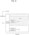
- FIG. 9 illustrates a subframe having an EPDCCH.
- a subframe may include a zero or one PDCCH region 410 or zero or more EPDCCH regions 420 and 430.
- the EPDCCH regions 420 and 430 are regions in which a wireless device monitors an EPDCCH.
- the PDCCH region 410 is located in up to four front OFDM symbols of a subframe, while the EPDCCH regions 420 and 430 may flexibly be scheduled in OFDM symbols after the PDCCH region 410.
- One or more EPDCCH regions 420 and 430 may be designated for the wireless device, and the wireless devices may monitor an EPDCCH in the designated EPDCCH regions 420 and 430.
- the number/location/size of the EPDCCH regions 420 and 430 and/or information on a subframe for monitoring an EPDCCH may be provided by a base station to a wireless device through an RRC message or the like.
- a PDCCH may be demodulated based on a CRS.
- a demodulation (DM) RS may be defined, instead of a CRS, for demodulation of an EPDCCH.
- An associated DM RS may be transmitted in the corresponding EPDCCH regions 420 and 430.
- N maxRB denotes the maximum number of RBs
- ns denotes the number of a slot in a radio frame
- l denotes the number of an OFDM symbol in a slot.
- a pseudo-random sequence c(i) is defined by the following gold sequence with a length of 31.
- ns is the number of a slot in a radio frame
- N EPDCCH,ID is a value associated with an EPDCCH set, which is given through a higher-layer signal
- n EPDCCH,SCID is a specific value.
- the EPDCCH regions 420 and 430 may be used for scheduling for different cells, respectively.
- an EPDCCH in the EPDCCH region 420 may carry scheduling information for a primary cell
- an EPDCCH in the EPDCCH region 430 may carry scheduling information for a secondary cell.
- EPDCCHs are transmitted in the EPDCCH regions 420 and 430 through multiple antennas, the same precoding as for the EPDCCHs may be applied to DM RSs in the EPDCCH regions 420 and 430.
- a transmission resource unit for an EPDCCH is an enhanced control channel element (ECCE).
- an EPDCCH search space may correspond to an EPDCCH region.
- one or more EPDCCH candidates may be monitored by one or more aggregation levels.
- An EPDCCH is transmitted using one or more ECCEs.
- An ECCE includes a plurality of enhanced resource element groups (EREGs).
- An ECCE may include four EREGs or eight EREGs according to a subframe type based on a TDD DL-UL configuration and a CP.
- an ECCE may include four EREGs in a normal CP, while an ECCE may include eight EREGs in an extended CP.
- a physical resource block (PRB) pair refers to two PRBs having the same RB number in one subframe.
- a PRB pair refers to a first PRB of a first slot and a second PRB of a second slot in the same frequency domain.
- a PRB pair includes 12 subcarriers and 14 OFDM symbols and thus includes 168 REs.
- FIG. 10 illustrates an example of a PRB pair.
- a subframe includes two slots and a PRB pair in one slot includes seven OFDM symbols and 12 subcarriers, these numbers of OFDM symbols and subcarriers are provided for illustrative purposes only.
- a PRB pair includes 168 REs.
- 16 EREGs are formed from 144 Res, excluding 24 REs for a DM RS,.
- one EREG may include nine REs.
- a CSI-RS or CRS may be disposed in one PRB pair in addition the DM RM.
- the number of available REs may be reduced and the number of REs included in one EREG may be reduced.
- the number of REs included in an EREG may change, while the number of EREGs included in one PRB pair, 16, does not change.
- 16 EREGs are assigned indexes from 0 to 15.
- nine REs having RE index 0 are allocated to EREG 0.
- nine REs having RE index k are allocated to EREG k.
- an ECCE may include four EREGs, and an ECCE may include eight EREGs in an extended CP.
- An ECCE is defined by an ERGE group. For example, FIG. 6 shows that ECCE #0 includes EREG group #0, ECCE #1 includes EREG group #1, ECCE #2 includes EREG group #2, and ECCE #3 includes EREG group #3.
- ECCE-to-EREG mapping There are localized transmission and distributed transmission in ECCE-to-EREG mapping.
- localized transmission an EREG group forming one ECCE is selected from EREGs in one PRB pair.
- distributed transmission an EREG group forming one ECCE is selected from EREGs in different PRB pairs.
- FIG. 11 illustrates a PUCCH and a PUSCH on an uplink subframe.
- Uplink control information may be transmitted to the PUCCH.
- the PUCCH transmits various types of control information according to a format.
- the UCI includes a HARQ ACK/NACK, a scheduling request (SR), and channel status information (CSI) representing a downlink channel status.
- PUCCH format 1 transmits a scheduling request (SR). In this case, an on-off keying (OOK) mode may be applied.
- PUCCH format 1a transmits an acknowledgement/non-acknowledgment (ACK/NACK) modulated by a binary phase shift keying (BPSK) mode with respect to one codeword.
- PUCCH format 1b transmits an ACK/NACK modulated by a quadrature phase shift keying (QPSK) mode with respect to two codewords.
- PUCCH format 2 transmits a channel quality indicator (CQI) modulated by the QPSK mode.
- PUCCH formats 2a and 2b transport the CQI and the ACK/NACK.
- Table 5 illustrates the PUCCH formats.
- SR Scheduling request
- CSI (20 code bits) Format 2
- Format 3 A plurality of ACK/NACKs for carrier aggregation
- Each PUCCH format is mapped in the PUCCH to be transmitted.
- the number N(2)RB of resource blocks which may be used in the PUCCH formats 2/2a/2b to which the CQI is transmitted may be indicated to the UE through a broadcasted signal.
- the aforementioned CSI is an index representing a status of the DL channel, and may include at least one of a channel quality indicator (CQI) and a precoding matrix indicator (PMI). Further, a precoding type indicator (PTI), a rank indication (RI), and the like may be included.
- CQI channel quality indicator
- PMI precoding matrix indicator
- PTI precoding type indicator
- RI rank indication
- the CQI provides information on link adaptive parameters which may be supported by the UE for a predetermined time.
- the CQI may indicate a data rate which may be supported by the DL channel by considering a characteristic of the UE receiver, a signal to interference plus noise ratio (SINR), and the like.
- the base station may determine modulation (QPSK, 16-QAM, 64-QAM, and the like) to be applied to the DL channel and a coding rate by using the CQI.
- the CQI may be generated by various methods.
- the various methods include a method of quantizing and feed-backing the channel status as it is, a method of calculating and feed-backing a signal to interference plus noise ratio (SINR), a method of notifying a status which is actually applied to the channel such as a modulation coding mode (MCS), and the like.
- SINR signal to interference plus noise ratio
- MCS modulation coding mode
- the CQI is generated based on the MCS
- the MCS includes a modulation mode, a coding mode, and a coding rate according to the coding mode, and the like.
- the PMI provides information on a precoding matrix in precoding based on a code book.
- the PMI is associated with the multiple input multiple output (MIMO).
- MIMO multiple input multiple output
- the feed-backing of the PMI in the MIMO may be called a closed loop MIMO.
- the RI is information on the number of layers recommended by the UE. That is, the RI represents the number of independent streams used in spatial multiplexing.
- the RI is fed-back only in the case where the UE operates in an MIMO mode using the spatial multiplexing.
- the RI is always associated with one or more CQI feed-backs. That is, the fed-back CQI is calculated by assuming a predetermined RI value. Since the rank of the channel is generally changed slower than the CQI, the RI is fed-back less than the number of CQIs.
- a transmission period of the RI may be a multiple of the CQI/PMI transmission period.
- the RI is defined in the entire system band, and a frequency-selective RI feedback is not supported.
- the PUCCH is used only in the transmission of the UCI.
- the PUCCH support multiple formats.
- a PUCCH having different bit numbers for each subframe may be used according to a modulation mode subordinate to the PUCCH format.
- Uplink data transmitted on the PUSCH may be a transmission block which is a data block for the UL-SCH transmitted during the TTI.
- the transmission block may include user data.
- the uplink data may be multiplexed data.
- the multiplexed data may be acquired by multiplexing the transmission block for the UL-SCH and the channel status information.
- the channel status information (CSI) multiplexed in the data may include the CQI, the PMI, the RI, and the like.
- the uplink data may be constituted by only the uplink status information. Periodic or aperiodic channel status information may be transmitted through the PUSCH.
- the PUSCH is allocated by the UL grant on the PDCCH. Although not illustrated, a fourth OFDM symbol of each slot of the normal CP is used in the transmission of a demodulation reference signal (DM RS) for the PUSCH.
- DM RS demodulation reference signal
- the hybrid automatic repeat request may be used.
- the HARQ is a technique in which a transmitter transmits data and thereafter, receives an acknowledgement/not-acknowledgement (ACK/NACK) as reception acknowledgement information for the data and transmits new data or retransmits pre-transmitted data according to the ACK/NACK.
- ACK/NACK acknowledgement/not-acknowledgement
- the ACK/NACK may be transmitted through the physical uplink control channel (PUCCH) which is an uplink control channel.
- PUCCH physical uplink control channel
- an index (this is referred to as a PUCCH index) for determining the PUCCH resource, that is, an index required for transmitting the ACK/NACK signal onto the PUCCH may be expressed by at least any one of (an orthogonal sequence index i, a cyclic shift index Ics, and a resource block index m) or an index n(1)PUCCH for acquiring the three indexes.
- the PUCCH resource may include at least any one of an orthogonal sequence, a cyclic shift, a resource bloc, and a combination thereof and an index which may represent the PUCCH resource may be referred to as the PUCCH index.
- the resource (the PUCCH resource) constituting the PUCCH may be implicitly or explicitly determined.
- the PUCCH resource may be determined based on a resource occupied by a control channel that schedules a physical downlink shared channel (PDSCH) or data (a transport block or codeword) which becomes a target of the ACK/NACK response and the PUCCH resource is referred to as an implicit PUCCH resource.
- PDSCH physical downlink shared channel
- data a transport block or codeword
- uplink reference signal will be described based on Rel-8, but other additional matters including uplink reference signal transmission, and the like in the multiple antennas will be referred together with Rel-10 or Rel-11.
- the reference signal is generally transmitted in sequence.
- a predetermined sequence may be used without a particular limit.
- a sequence PSK-based computer generated sequence
- PSK phase shift keying
- Examples of the PSK include binary phase shift keying (BPSK), quadrature phase shift keying (QPSK), and the like.
- BPSK binary phase shift keying
- QPSK quadrature phase shift keying
- a constant amplitude zero autocorrelation (CAZAC) sequence may be used as the reference signal sequence.
- the CAZAC sequence include a zadoff-chu (ZC) based sequence, a ZC sequence with cyclic extension, a ZC sequence with truncation, and the like.
- a pseudo-random (PN) sequence may be used as the reference signal sequence.
- PN sequence include an m-sequence, a sequence generated through the computer, a gold sequence, a Kasami sequence, and the like.
- a cyclically shifted sequence may be used as the reference signal sequence.
- the uplink reference signal may be divided into the demodulation reference signal (DMRS) and the sounding reference signal (SRS).
- DMRS is a reference signal used in the channel estimation for demodulating a received signal.
- the DMRS may be associated with transmission of a PUSCH or PUCCH.
- SRS is a reference signal which the terminal transmits to a base station for uplink scheduling.
- the base station estimates an uplink channel through the received sounding reference signal and uses the estimated uplink channel in the uplink scheduling.
- the SRS is not associated with transmission of the PUSCH or PUCCH.
- the same type of primary sequence may be used for the DMRS and the SRS.
- precoding applied to the DMRS in uplink multi-antenna transmission may be the same as precoding applied to the PUSCH.
- Cyclic shift separation is a primary mode that multiplexes the DMRS.
- the SRS may not be precoded and further, may an antenna specific reference signal.
- the SRS as a reference signal which the terminal or a relay station transmits to the base station is a reference signal which is not associated with uplink data or control signal transmission.
- the SRS may be generally used for channel quality estimation for frequency selective scheduling in the uplink or used for another purpose.
- the SRS may be used in power control or initial MCS selection, initial power control for data transmission, and the like.
- the SRS is generally transmitted in a last SC-FDMA symbol of one subframe.
- the reference signal sequence r u,v ( ⁇ ) (n) may be defined based on a primary sequence b u,v (n) and a cyclic shift ⁇ by Equation 4.
- r u , v ⁇ n e j ⁇ n b u , v n , 0 ⁇ n ⁇ M sc RS
- N sc RB represents the size of a resource block represented by the number of subcarriers in the frequency domain and N RB max,UL represents a maximum value of an uplink bandwidth represented by the multiple of N sc RB .
- a plurality of reference signal sequences may be defined by differently applying ⁇ which is the cyclic shift value from one primary sequence.
- the primary sequence b u,v (n) is divided into a plurality of groups and in this case, u ⁇ ⁇ 0,1,...,29 ⁇ represents a group index and v represents a primary sequence index in a group.
- the primary sequence depends on the length (M sc RS ) of the primary sequence.
- a sequence group index u and a primary sequence index v in the group may vary depending on a time like group hopping or sequence hopping.
- n SRS cs is a value configured by a higher layer with respect to each terminal and may be any one among integers of 0 to 7.
- the SRS sequence is mapped to a resource element by multiplying ⁇ SRS which is an amplitude scaling factor in order to satisfy transmission power P SRS .
- Equation 6 k 0 represents a starting position in the frequency domain of the SRS and M sc,b RS represents the length of the SRS sequence defined by Equation 7.
- M sc , b RS m SRS , b N sc RB / 2
- m SRS,b may be given by Tables 6 to 9 to be described below with respect to each uplink bandwidth N RB UL .
- k TC ⁇ ⁇ 0,1 ⁇ represents a parameter given to the terminal by the higher layer and n b represents a frequency position index.
- the frequency hopping of the SRS is configured by a parameter b hop ⁇ ⁇ 0,1,2,3 ⁇ given by the higher layer.
- the frequency position index n b is determined by Equation 9.
- n b ⁇ ⁇ 4 n RRC / m SRS , b ⁇ mod N b b ⁇ b hop F b n SRS + ⁇ 4 n RRC / m SRS , b ⁇ mod N b otherwise
- N b may be determined by Tables 6 to 9 to be described and F b (n SRS ) may be determined by Equation 10.
- n SRS represents the number of terminal specific SRS transmission times and may be determined by Equation 11.
- n SRS ⁇ 2 N SP n f + 2 N SP ⁇ 1 ⁇ n s 10 ⁇ + ⁇ T offset T offset_ max ⁇ , for 2 ms SRS periodicity of frame structure 2 ⁇ n f ⁇ 10 + ⁇ n s / 2 ⁇ / T SRS ⁇ , otherwise
- T SRS represents terminal specific periodicity of the SRS transmission
- T offset represents an SRS subframe offset
- T offset_max represents a maximum value of T offset for a specific configuration of the SRS subframe offset.
- T SRS and T offset may be given by Tables 12 and 13 to be described below.
- Tables 6 to 9 show one example of an SRS bandwidth configuration.
- 3-bit cell specific parameters may be broadcasted in order to indicate one bandwidth configuration of 8 bandwidth configurations.
- 2-bit terminal specific parameters may be given from the higher layer in order to indicate one bandwidth configuration of 4 bandwidth configurations.
- Tables 10 and 11 show one example of a cell specific subframe configuration periodicity parameter T SFC for the SRS transmission and one example of a cell specific subframe offset parameter ⁇ SFC .
- Table 10 shows one example of an SRS subframe configuration in an FDD system.
- the SRS subframe configuration may be indicated by a parameter having a length of 4 bits and the periodicity of the SRS subframe may be any one of subframes 1, 2, 5, and 10.
- Table 11 shows one example of an SRS subframe configuration in a TDD system.
- Table 11 srsSubframeConfiguration Binary Configuration Period T SFC (subframes) Transmission offset ⁇ SFC (subframes) 0 0000 5 ⁇ 1 ⁇ 1 0001 5 ⁇ 1,2 ⁇ 2 0010 5 ⁇ 1,3 ⁇ 3 0011 5 ⁇ 1,4 ⁇ 4 0100 5 ⁇ 1,2,3 ⁇ 5 0101 5 ⁇ 1,2,4 ⁇ 6 0110 5 ⁇ 1,3,4 ⁇ 7 0111 5 ⁇ 1,2,3,4 ⁇ 8 1000 10 ⁇ 1,2,6 ⁇ 9 1001 10 ⁇ 1,3,6 ⁇ 10 1010 10 ⁇ 1,6,7 ⁇ 11 1011 10 ⁇ 1,2,6,8 ⁇ 12 1100 10 ⁇ 1,3,6,9 ⁇ 13 1101 10 ⁇ 1,4,6,7 ⁇ 14 1110 reserved reserved 15 1111 reserved reserved reserved
- the transmission power P SRS in subframe i may be determined by Equation 12.
- P SRS i min P CMAX , P SRS_OFFSET + 10 log 10 M SRS + P O_PUSCH j + ⁇ j ⁇ PL + f i
- P CMAX represents the transmission power of a predetermined terminal.
- P SRS_OFFSET represents a terminal specific parameter having a length of 4 bits, which is semi-statically determined by the higher layer.
- Ks 1.25
- P SRS_OFFSET may be determined by the unit of 1 dB in the range of [-3, 12] dB.
- M SRS represents the bandwidth of the SRS transmission, which is represented by the number of resource blocks and P O_PUSCH (j) represents a parameter configured by the sum of P O_NOMINAL_PUSCH (j) which is a cell specific nominal component given by the higher layer and P O_UE_PUSCH (j) which is a terminal specific component given by the higher layer.
- ⁇ (j) represents a 3-bit cell specific parameter given by the higher layer
- PL represents an estimation value of path loss calculated by the terminal
- f(i) represents a current power control adjustment state for the PUSCH.
- a n SRS ⁇ n SRS + ⁇ n SRS / 2 ⁇ + ⁇ ⁇ ⁇ n SRS / K ⁇ mod 2 when K is even n SRS mod 2 when K is odd
- B SRS represents an SRS bandwidth and b hop represents a frequency hopping bandwidth.
- the corresponding SC-FDMA symbol may be used for transmitting the SRS.
- the UpPTS uplink pilot time slot
- two SC-FDMA symbols may be all used for transmitting the SRS and simultaneously assigned to one terminal.
- the terminal When the transmission of the SRS and transmission of PUCCH format 2/2a/2b simultaneously occur in the same subframe, the terminal does not transmit the SRS.
- an ackNackSRS-SimultaneousTransmission parameter is false, when the SRS transmission and transmission of the PUCCH transporting the ACK/NACK and/or a positive SR are performed in the same subframe, the terminal does not continuously transmit the SRS. Further, if an ackNackSRS-SimultaneousTransmission parameter is true, when the SRS transmission and the transmission of the PUCCH transporting the ACK/NACK and/or the positive SR are configured in the same subframe, the terminal uses a shortened PUCCH format and simultaneously transmits the PUCCH transporting the ACK/NACK and/or the positive SR and the SRS.
- the terminal uses the shortened PUCCH format and simultaneously transmits the PUCCH transporting the ACK/NACK and/or the positive SR and the SRS.
- the SRS transmission overlaps with a physical random access channel (PRACH) region for preamble format 4 or exceeds the range of an uplink system bandwidth configured in the cell, the terminal does not transmit the SRS.
- PRACH physical random access channel
- the ackNackSRS-SimultaneousTransmission which is the parameter given by the higher layer determines whether support that the terminal simultaneously transmits the PUCCH transporting the ACK/NACK and the SRS in one subframe.
- the terminal may transmit the ACK/NACK and the SRS in the cell specific SRS subframe.
- the shortened PUCCH format may be used and transmission of the ACK/NACK or SR corresponding to a position where the SRS is transmitted is omitted (punctured).
- the shortened PUCCH format is used in the cell specific SRS subframe even when the terminal does not transmit the SRS in the corresponding subframe.
- the terminal may use general PUCCH format 1/1a/1b in order to transmit the ACK/NACK and the SR.
- Tables 12 and 13 show one example of the terminal specific SRS configuration indicating T SRS which is the SRS transmission periodicity and T offset which is the SRS subframe offset.
- the SRS transmission periodicity T SRS may be determined as any one of ⁇ 2, 5, 10, 20, 40, 80, 160, 320 ⁇ ms.
- Table 12 shows one example of the SRS configuration in the FDD system.
- SRS Configuration Index I SRS SRS Periodicity T SRS (ms)
- SRS Subframe Offset T offset 0 - 1 2 I SRS 2 - 6 5
- I SRS - 7 17 - 36 20
- I SRS - 17 37 - 76 40
- I SRS - 37 77 - 156 80
- I SRS - 77 157 - 316 160
- I SRS - 157 317 - 636 320
- I SRS - 317 637 - 1023 reserved reserved
- Table 13 shows one example of the SRS configuration in the TDD system.
- Configuration Index I SRS SRS Periodicity T SRS (ms) SRS Subframe Offset T offset 0 2 0, 1 1 2 0,2 2 2 1,2 3 2 0,3 4 2 1,3 5 2 0,4 6 2 1,4 7 2 2,3 8 2 2,4 9 2 3,4 10 - 14 5 I SRS - 10 15 - 24 10 I SRS - 15 25 - 44 20 I SRS - 25 45 - 84 40 I SRS - 45 85 - 164 80 I SRS - 85 165 - 324 160 I SRS - 165 325 - 644 320 I SRS - 325 645 - 1023 reserved reserved reserved
- n f represents a frame index and k SRS represents a subframe index in the frame in the FDD system.
- T SRS 2
- k SRS of Equation 13 may be determined by Table 14. [Table 14] subframe index n 0 1 2 3 4 5 6 7 8 9 1st symbol ofUpPTS 2nd symbol ofUpPTS 1st symbol of UpPTS 2nd symbol of UpPTS k SRS in case UpPTS length of 2 symbols 0 1 2 3 4 5 6 7 8 9 k SRS in case UpPTS length of 1 symbol 1 2 3 4 6 7 8 9
- the terminal does not continuously transmit the SRS.
- An SRS transmitting method may be divided into two types.
- a method defined in LTE rel-8 includes a periodic SRS transmitting method that periodically transmits the SRS according to an SRS parameter received by radio resource control (RRC) signaling and an aperiodic SRS transmitting method that transmits the SRS whenever necessary based on a message dynamically triggered from the base station.
- RRC radio resource control
- the aperiodic SRS transmitting method may be adopted.
- the SRS may be transmitted in the terminal specific SRS subframe which is UE-specifically determined.
- the cell specific SRS subframe is periodically configured by the cell specific SRS parameter and a periodic SRS is transmitted in a periodic terminal specific SRS subframe configured by the terminal specific SRS parameter among the cell specific SRS subframes.
- the periodic terminal specific SRS subframe may be a subset of the cell specific SRS subframe.
- the cell specific SRS parameter may be given by the higher layer.
- an aperiodic SRS may be transmitted in an aperiodic terminal specific SRS subframe determined by a terminal specific aperiodic SRS parameter.
- the aperiodic terminal specific SRS subframe in the aperiodic SRS transmitting method may be a subset of the cell specific SRS subframe as defined in the LTE rel-8. Alternatively, the aperiodic terminal specific SRS subframe may be the same as the cell specific SRS subframe.
- the terminal specific aperiodic SRS parameter may also be given by the higher layer similarly to the cell specific SRS parameter.
- the terminal specific aperiodic SRS subframe may be configured by the subframe periodicity and the subframe offset of Table 7 or 8 described above.
- a situation may be considered, in which the PUCCH is transmitted in a secondary cell (SCell) for the purpose of offloading for the PUCCH even with respect to a cell or a cell group having the same geographical position in a next system.
- SCell secondary cell
- the SCell that may transmit the PUCCH may be determined in a step in which the terminal configures the corresponding serving cell and it may be considered that a plurality of configured cells dynamically selects the cell that will transmit the PUCCH.
- the cell that may transmit the PUCCH will be referred to as a primary cell (PCell) and/or a primary SCell (pSCell) for easy description.
- PCell primary cell
- pSCell primary SCell
- An uplink (UL) channel environment needs to be considered in selecting the pSCell and estimating a channel environment of each serving cell through the SRS which the terminal transmits may be considered.
- Selecting the PUSCH and the PUCCH based on the same SRS through the SRS transmission (including a hopping mode) for the full uplink bandwidth (UL BW) including the PUCCH region in a situation in which downlink (DL) traffic and uplink traffic are similar may be considered.
- a general situation is a situation in which the downlink traffic is relatively higher than the uplink traffic and in this case, a situation in which a transmission frequency of the PUCCH is higher than a transmission frequency of the PUSCH may be considered.
- uplink (UL) overhead may be inefficient.
- the uplink overhead may be more inefficient in a situation in which the uplink of the SCell is guaranteed.
- separately configuring the SRS for the PUSCH and the SRS (including all channels/signals that enable the base station to estimate uplink performance of the PUCCH) for the PUCCH may be advantageous in terms of the uplink overhead.
- the base station may configure whether to additionally transmit the SRS for the PUCCH in configuring the SRS with respect to the PUSCH in the related art to the terminal through the higher layer and when whether to additionally transmit the SRS for the PUCCH is configured, additionally configuring the configuration for the corresponding SRS may be considered.
- the disclosures of the present specification propose a detailed configuration or transmission mode for the SRS for the PUCCH in a PUCCH offloading situation.
- a first disclosure among the disclosures of the present specification presents an offloading target configuring mode for the PUCCH
- a second disclosure among the disclosures of the present specification presents a configuration mode of the SRS configuration
- a third disclosure among the disclosures of the present specification presents a detailed configuration mode for the SRS.
- the configuration mode of the offloading target for the PUCCH is described.
- a UCI which may be transmitted through the PUCCH may be constituted by a scheduling request (SR), an HARQ-ACK, a periodic CSI, and the like.
- a method for allocating resources in PUCCH format 1a/1b, PUCCH format 1b (with channel selection), PUCCH format 2/2a/2b, PUCCH format 3, and the like as transmission formats, respectively and the number of resources which may be simultaneously transmitted per RB may be independently designated.
- the PUCCH to be offloaded may be differently configured according to the UCI to be transmitted or the PUCCH format and the offloading may be performed with respect to all PUCCH transmissions.
- the mode 1-1 is a mode that performs offloading of all UCIs.
- the mode 1-2 is a mode that performs offloading of only the periodic CSI.
- the mode 1-2 may be limited to a case of the SR subframe and in particular, limited to a case in which the SR is transmitted in the SR subframe. In this case, the SR and the periodic CSI may be simultaneously transmitted.
- the mode 1-3 is a mode that performs offloading of only the HARQ-ACK.
- the mode 1-4 is a mode that performs offloading of only the SR.
- the mode 1-4 may be limited to a subframe in which the periodic CSI is transmitted.
- the SR and the periodic CSI may be simultaneously transmitted.
- the mode 1-5 is a mode that performs offloading of only the HARQ-ACK and the SR.
- the mode 1-6 is a mode that performs offloading of the remainder other than the UCI corresponding to the PCell.
- the mode 1-7 is a mode that performs offloading of the remainder other than PCell HARQ-ACK and/or SR.
- the mode 1-8 is a mode that the base station signals the UCI to be offloaded to the terminal through the higher layer and the terminal performs the PUCCH offloading based on the corresponding information.
- a UCI which is not offloaded may be transmitted through the PCell.
- the offloaded PUCCH may be transmitted with respect to all serving cells including the PCell.
- the mode 2-1 is a mode that performs offloading of all PUCCH formats.
- the mode 2-2 is a mode that performs offloading of only PUCCH format 1.
- the mode 2-3 is a mode that performs offloading of only PUCCH format 1/1a/1b. In detail, channel selection may be excluded in the case of PUCCH format 1b.
- the mode 2-4 is a mode that performs offloading of only PUCCH format 2/2a/2b.
- the mode 2-5 is a mode that performs offloading of only PUCCH format 3.
- the mode 2-6 is a mode that performs offloading of only PUCCH format 1/1a/1b/3.
- the mode 2-7 is a mode that the base station signals each format to be offloaded to the terminal through the higher layer and the terminal performs the PUCCH offloading based on the corresponding information.
- the UCI which is not offloaded may be transmitted through the PCell and selecting the PUCCH to be offloaded may be configured through combining a simultaneous transmission configuration of the UCI and the format.
- the configuration for the PUCCH SRS may be additionally configured independently from the configuration for the SRS (the SRS of Rel-11 in the related art) for the PUSCH.
- the configuration may be constituted by periodicity, SF offset, cell-specific bandwidth configuration, UE-specific bandwidth configuration, and the like (see the Rel-11).
- the SRS subframe region is shared by the PUSCH.
- the SRS transmittable subframe for the PUCCH when designated as a region that satisfies ⁇ n s /2 ⁇ mod T SFC ⁇ ⁇ SFC , the SRS transmittable subframe for the PUSCH may be designated as a region that satisfies ( ⁇ n s /2 ⁇ - offset 1)mod m 1 T SFC ⁇ ⁇ SFC .
- offset 1 and m 1 may be values configured for the terminal in the base station and it may be considered that the values are also expressed in a reverse form.
- a mode may be adopted, in which the SRS for the PUSCH depends on aperiodic SRS (type 1 SRS) and the SRS for the PUCCH depends on periodic SRS (type 0 SRS).
- the SRS for the PUSCH and the SRS for the PUCCH in the related art with respect to a single cell may collide with each other in the same subframe and an execution procedure for the collision may be required.
- simultaneous transmission of the SRS for the PUSCH and the SRS for the PUCCH may not be supported and in this case, a priority between both SRSs needs to be configured. Configuring the priority based on the channel which becomes the target of the corresponding SRS may be considered.
- the mode 3-1 is a mode that configures the priority of the SRS for the PUCCH to be higher than the priority of the SRS for the PUSCH.
- the mode 3-1 may be to configure the priority of the PUCCH to be higher than the priority of the PUSCH and efficiently manage downlink (DL) throughput performance.
- the mode 3-2 is a mode that configures the priority based on a range of a bandwidth (BW) covered by the SRS according to a configuration with respect to heterogeneous SRSs.
- BW bandwidth
- a start point and an end point of a full BW covered by the SRS may be compared with each other and thereafter, the priority may be determined based on the amount of the covered region.
- the bandwidths of the SRS for the PUSCH and the SRS for the PUCCH are an entire region (in a non-contiguous case, a location where the frequency index is the lowest and a location where the frequency index is the highest) and in the case of the SRS for the PUSCH, when the SRS may be transmitted even with respect to a middle region even in addition to both ends, the priority of the SRS for the PUSCH may be configured to be high.
- the mode 3-3 is a mode that configures the priority through the higher layer.
- the mode 3-4 is a mode that configures the priority of the SRS for the PUSCH to be higher than the priority of the SRS for the PUCCH in order to conserve the existing operation.
- the SRS for the PUSCH may be construed as the SRS of the Rel-11 and the SRS for the PUCCH may be construed as an additionally adopted SRS.
- the mode 4-1 is a mode that configures the priority of the SRS for the PUCCH to be higher than the priority of the SRS for the PUSCH.
- the mode 3-1 may be to configure the priority of the PUCCH to be higher than the priority of the PUSCH and efficiently manage the downlink (DL) throughput performance.
- the mode 4-2 is a mode that configures the priority based on the range of the bandwidth (BW) covered by the SRS according to the configuration with respect to the heterogeneous SRSs.
- the start point and the end point of the full BW covered by the SRS may be compared with each other and thereafter, the priority may be determined based on the amount of the covered region.
- the bandwidths of the SRS for the PUSCH and the SRS for the PUCCH are the entire region (in a non-contiguous case, a location where the frequency index is the lowest and the location where the frequency index is the highest) and in the case of the SRS for the PUSCH, when the SRS may be transmitted even with respect to the middle region even in addition to both ends, the priority of the SRS for the PUSCH may be configured to be high.
- the mode 4-3 is a mode that configures the high priority in the SRS corresponding to the PCell when the SRS is transmitted in the PCell.
- the mode 4-3 is a mode that configures the priority of the SRS corresponding to a cell having the lowest SCell index among SCells to be high when the SRS is not transmitted in the PCell.
- the SRS for the PUSCH when the SRS for the PUSCH is transmitted in the PCell, the SRS for the PUSCH may have the higher priority than the SRS for the PUCCH.
- the mode 4-4 is a mode that configures the priority through the higher layer.
- the SRS for the PUSCH and the SRS for the PUCCH may be simultaneously transmitted, it may be considered that power scaling may be considered with respect to all SRSs to be transmitted like the Rel-11 in the related art with respect to a power limited terminal.
- weighted scaling considering a weighted value with respect to one SRS among the heterogeneous SRSs may be considered.
- the selected SRS may be an SRS corresponding to the PUCCH.
- the selected SRS may be an SRS corresponding to the PCell or an SRS corresponding to an SCell having the lowest SCell index when there is no PCell.
- the priority between the SRS for other channel and the SRS for the PUCCH it may be assumed that the priority for the PUCCH also has the same priority as the SRS of the Rel-11 in the related art.
- the periodic SRS for the PUCCH may have a lower priority than the periodic CSI.
- the SRS configuring mode is described.
- the method according to the third disclosure of the present specification as a method for transmitting a sound reference signal (SRS) by a terminal in a wireless communication system may include: receiving an SRS configuration from a base station by the terminal; determining an SRS subframe to which the SRS is to be transmitted among a plurality of subframes and an SRS transmission region to which the SRS is to be transmitted in a physical uplink control channel (PUCCH) region on the SRS subframe, on the basis of the received SRS configuration; and transmitting the SS to the SRS transmission region on the determined SRS subframe.
- PUCCH physical uplink control channel
- the SRS and the PUCCH may be multiplexed on the basis of code division multiplexing (CDM).
- CDM code division multiplexing
- the multiplexing may be based on an orthogonal cover code (OCC).
- OCC orthogonal cover code
- the SRS subframe may include two slots including a plurality of orthogonal frequency division multiplexing (OFDM) symbols and the SRS may be transmitted in the last OFDM symbol in each of the two slots.
- OFDM orthogonal frequency division multiplexing
- the SRS may be transmitted to be symmetric based on the center of the uplink bandwidth.
- the SRS subframe may include two slots including the plurality of OFDM symbols and the SRS may be transmitted in any one OFDM symbol of each of the two slots.
- the any one OFDM symbol may be designated in the SRS configuration or predesignated according to a radio network temporary identifier (RNTI) of the terminal.
- RNTI radio network temporary identifier
- the SRS subframe may include two slots including the plurality of orthogonal frequency division multiplexing (OFDM) symbols and the SRS may be transmitted in the OFDM symbol corresponding to all or some of the DMRSs among the plurality of OFDM symbols.
- OFDM orthogonal frequency division multiplexing
- the SRS may be transmitted based on PUCC format 3.
- the SRS may be transmitted onto the PUCCH resource allocated based on the UL grant.
- the SRS may be transmitted in a frequency hopping form by the unit (a period depending on the SRS subframe configuration) of the subframe in the PUSCH region other than the PUCCH region or a full uplink bandwidth region (only for the UpPts) according to the configuration.
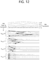
- FIG. 12 illustrates one example of SRS transmission depending on an SRS bandwidth configuration for each subframe or subframe bundle unit.
- a method that configures the corresponding SRS so as to transmit the SRS in the full uplink bandwidth (even in a normal subframe) in the SRS for the PUSCH in the related art may be considered and adopting a new SRS may be considered.
- the new SRS may be an SRS sequence form or a partial symbol form of the PUCCH.
- the SBS may be transmitted in the full uplink bandwidth according to the SRS only for the UpPts. The reason is that the PUCCH is not transmitted in the UpPts.
- the SRS may be transmitted at least with respect to a region other than 1 RB (a total of 2 RBs) at both ends of the bandwidth for a partial uplink bandwidth.
- a section in which the SRS is transmittable is configured to include the full bandwidth region with respect to all uplink bandwidths.
- a value of m SRS,0 configured for each uplink bandwidth in configuring the SRS bandwidth may be modified or added to have a value of the corresponding uplink bandwidth.
- the SRS may be configured to be transmitted in the full uplink bandwidth by adding an offset in calculating M sc , b RS designating the length of an SRS sequence and k 0 p representing a frequency start position for the SRS.
- the offset may be a signal which the base station configures and signals for the terminal or a predetermined value.
- the offset may be 0 or nonzero according to whether to support the SRS for the PUCCH.
- Equations given below show detailed examples regarding the addition of the offset.
- estimating the channel quality for the PUCCH region may be inefficient by an SRS drop depending on the PUCCH transmission. Further, in the above case, while even the SRS for the PUSCH is simultaneously dropped, the PUSCH transmission may also be inefficiently operated.
- the SRS may be transmitted in the full uplink bandwidth, in particular, a region including the PUCCH region and even in the case of a hopping pattern, only the PUCCH region or a region in which the SRS is not transmitted may be designated.
- a mode through the additional offset may be considered like the mode that extends the SRS in the related art or redefining the SRS bandwidth configuration may be considered.
- the Rel-11 SRS in the related art is configured to be transmitted only in the PUSCH region in order to estimate the PUSCH channel quality and the base station may configure to transmit the additionally SRS only in the PUCCH region for the terminal.
- Adopting the new SRS may be considered in order to estimate the channel quality of the PUCCH region.
- the SRS may be transmitted in a plurality of frequency regions in order to show an effect for slot hopping (a mapping structure of a frequency hopping form with respect to the slot in the subframe) of the PUCCH.
- the SRS for the PUCCH is transmitted simultaneously in RB index m and N RB UL ⁇ m in the last OFDM symbol of the subframe in which the SRS is transmitted when the uplink bandwidth is N RB UL ,
- FIG 13 illustrates one example for a case where an SRS for the PUSCH and an SRS for the PUCCH are simultaneously transmitted.
- the terminal needs to be able to support non-contiguous transmission even with respect to the same band.
- the configuration scheme B relates to a case where simultaneous transmission of the PUCCH and since the PUSCH is configured and the corresponding second SRS may be frequently dropped at the time of the additional PUCCH transmission, the configuration scheme may be a case where the shortened PUCCH is configured and may relate to a case where the PUCCH region in which the second SRS is transmitted is also a region for PUCCH format 1/1a/1b/3.
- the PUCCH may have a plurality of PUCCH resources in the same RB and each PUCCH resource may be divided in a combination form of the cyclic shift and/or the orthogonal cover code (OCC).
- OCC orthogonal cover code
- the appropriate cyclic shift value is allocated to the second SRS (the SRS for the PUCCH)
- the mode C-1 is a mode that transmits the last OFDM symbol of each slot in a region where the transmission of the second SRS is configured.
- FIG 14 illustrates an SRS transmission method depending on a C-1-th method.
- the frequency domains of the SRSs transmitted in the respective slots may be symmetric to each other based on the center with respect to the uplink bandwidth.
- the SRS when the SRS is transmitted in RB index m in a first slot, the SRS is transmitted in RB index N RB UL ⁇ m in a second slot.
- the mode C-2 is a mode that transmits the SRS in one OFDM symbol of each slot in the region where the transmission of the second SRS is configured.
- the base station may announce the OFDM symbol at the time of configuring the second SRS and the OFDM symbol may be predesignated according to a terminal RNTI. Therefore, more SRS resources may be secured.
- the mode C-3 is a mode that transmits the second SRS in the OFDM symbol corresponding to all or some of the DMRSs.
- the mode C-3 may be applied in the case of PUCCH format 3.
- the reason may be that the CDM of the data region may be performed through the OCC in the case of PUCCH format 3.
- the mode C-4 is a mode that the base station allocates the PUCCH resource to the terminal and the terminal transmits the PUCCH according to the allocated PUCCH resource.
- the PUCCH may be construed as the second SRS.
- the PUCCH may operate based on the uplink grant.
- the PUCCH resource may be included in the corresponding uplink grant.
- the mode may be applied differently for each PUCCH format.
- the aperiodic SRS when the aperiodic SRS is configured, it may be considered that a new format is added with respect to the DCI for triggering the corresponding SRS and it may be considered that the existing SRS field is reused or added.
- triggering for the first SRS or triggering for the second SRS may be distinguished according to the subframe in which the corresponding DCI is transmitted.
- the DCI is transmitted after 4 subframes from the subframe in which the DCI for the triggering is transmitted without being limited to the SRS subframe.
- FIG. 15 is a block diagram illustrating a wireless communication system in which a disclosure of the present specification is implemented.
- a base station 200 includes a processor 201, a memory 202, and a radio frequency (RF) unit 203.
- the memory 202 is connected with the processor 201 to store various pieces of information for driving the processor 201.
- the RF unit 203 is connected with the processor 201 to transmit and/or receive a radio signal.
- the processor 201 implements a function, a process, and/or a method which are proposed. In the aforementioned embodiment, the operation of the base station may be implemented by the processor 201.
- a terminal 100 includes a processor 101, a memory 102, and an RF unit 103.
- the memory 102 is connected with the processor 101 to store various pieces of information for driving the processor 101.
- the RF unit 103 is connected with the processor 101 to transmit and/or receive a radio signal.
- the processor 101 implements a function, a process, and/or a method which are proposed.
- the processor may include an application-specific integrated circuit (ASIC), another chip set, a logic circuit and/or a data processing apparatus.
- the memory may include a read-only memory (ROM), a random access memory (RAM), a flash memory, a memory card, a storage medium, and/or other storage device.
- the RF unit may include a baseband circuit for processing the radio signal.
- the aforementioned technique may be implemented by a module (a process, a function, and the like) that performs the aforementioned function.
- the module may be stored in the memory and executed by the processor.
- the memory may be positioned inside or outside the processor and connected with the processor by various well-known means.
- a terminal for transmitting a sound reference signal (SRS) in a wireless communication system may include: an RF unit receiving an SRS configuration from a base station by the terminal; and a processor controlling the RF unit to determine an SRS subframe to which the SRS is to be transmitted among a plurality of subframes and an SRS transmission region to which the SRS is to be transmitted in a physical uplink control channel (PUCCH) region on the SRS subframe, on the basis of the received SRS configuration and transmit the SRS to the SRS transmission region on the determined SRS subframe.
- PUCCH physical uplink control channel
- the SRS and the PUCCH may be multiplexed on the basis of code division multiplexing (CDM).
- CDM code division multiplexing
- the SRS subframe may include two slots including a plurality of orthogonal frequency division multiplexing (OFDM) symbols and the SRS may be transmitted in any one OFDM symbol in each of the two slots.
- OFDM orthogonal frequency division multiplexing
- the any one OFDM symbol may be designated in the SRS configuration or predesignated according to a radio network temporary identifier (RNTI) of the terminal.
- RNTI radio network temporary identifier
- any one OFDM symbol may be the last symbol of each of the two slots.
- the SRS may be transmitted to be symmetric based on the center of the uplink bandwidth.
Landscapes
- Engineering & Computer Science (AREA)
- Signal Processing (AREA)
- Computer Networks & Wireless Communication (AREA)
- Mobile Radio Communication Systems (AREA)
Applications Claiming Priority (2)
| Application Number | Priority Date | Filing Date | Title |
|---|---|---|---|
| US201461981847P | 2014-04-20 | 2014-04-20 | |
| PCT/KR2015/003883 WO2015163645A1 (ko) | 2014-04-20 | 2015-04-17 | 무선 통신 시스템에서의 사운딩 참조 신호 전송 방법 및 단말 |
Publications (3)
| Publication Number | Publication Date |
|---|---|
| EP3136641A1 true EP3136641A1 (de) | 2017-03-01 |
| EP3136641A4 EP3136641A4 (de) | 2017-12-20 |
| EP3136641B1 EP3136641B1 (de) | 2019-07-24 |
Family
ID=54332747
Family Applications (1)
| Application Number | Title | Priority Date | Filing Date |
|---|---|---|---|
| EP15782272.7A Active EP3136641B1 (de) | 2014-04-20 | 2015-04-17 | Verfahren und endgerät zur übertragung eines klangreferenzsignals in einem drahtloskommunikationssystem |
Country Status (4)
| Country | Link |
|---|---|
| US (1) | US10291377B2 (de) |
| EP (1) | EP3136641B1 (de) |
| CN (1) | CN106233658B (de) |
| WO (1) | WO2015163645A1 (de) |
Cited By (3)
| Publication number | Priority date | Publication date | Assignee | Title |
|---|---|---|---|---|
| EP3528565A4 (de) * | 2016-11-04 | 2019-10-30 | Huawei Technologies Co., Ltd. | Verfahren zur übertragung eines klangreferenzsignals sowie netzwerkvorrichtung und endgerätevorrichtung |
| EP3536071A4 (de) * | 2016-11-04 | 2020-03-11 | MediaTek Inc. | Verfahren und vorrichtung zum multiplexen von physikalischen uplink-steuerkanälen in der mobilen kommunikation |
| WO2022047717A1 (en) * | 2020-09-04 | 2022-03-10 | Qualcomm Incorporated | Group common downlink control information enhancements for partial frequency sounding of multiple ues |
Families Citing this family (47)
| Publication number | Priority date | Publication date | Assignee | Title |
|---|---|---|---|---|
| US8660057B2 (en) * | 2010-08-26 | 2014-02-25 | Golba, Llc | Method and system for distributed communication |
| CN106717091A (zh) * | 2014-09-04 | 2017-05-24 | 华为技术有限公司 | 用于针对d2d传送资源分配的系统和方法 |
| US9930654B2 (en) * | 2015-03-17 | 2018-03-27 | Motorola Mobility Llc | Method and apparatus for scheduling user equipment uplink transmissions on an unlicensed carrier |
| US10980022B2 (en) * | 2015-12-04 | 2021-04-13 | Qualcomm Incorporated | Coupled mode common uplink burst in TDD subframe structure |
| US10917878B2 (en) * | 2016-03-11 | 2021-02-09 | Qualcomm Incorporated | Techniques for acknowledging scheduling request transmissions on a contention-based physical uplink shared channel |
| WO2017171901A1 (en) * | 2016-03-29 | 2017-10-05 | Intel IP Corporation | Frame structures for beam switching and refinement in cellular systems |
| WO2017166321A1 (zh) * | 2016-04-01 | 2017-10-05 | 华为技术有限公司 | 上行信息传输方法、终端设备及接入网设备 |
| WO2017196483A1 (en) * | 2016-05-13 | 2017-11-16 | Intel IP Corporation | Multi-user multiple input multiple ouput systems |
| JP6891419B2 (ja) * | 2016-07-29 | 2021-06-18 | ソニーグループ株式会社 | 端末装置、基地局、方法及び記録媒体 |
| CN107888355B (zh) * | 2016-09-30 | 2021-07-30 | 中兴通讯股份有限公司 | 测量参考信号的发送方法及装置、接收方法及装置 |
| KR20180049781A (ko) * | 2016-11-03 | 2018-05-11 | 삼성전자주식회사 | 빔포밍 시스템에서 단말의 송신 전력 제어 방법 및 장치 |
| WO2018084626A1 (ko) | 2016-11-03 | 2018-05-11 | 삼성전자 주식회사 | 빔포밍 시스템에서 단말의 송신 전력 제어 방법 및 장치 |
| CN108632977B (zh) * | 2017-03-24 | 2023-04-07 | 中兴通讯股份有限公司 | 功率状态转换方法及装置、终端、存储介质、处理器 |
| US10547422B2 (en) * | 2017-04-13 | 2020-01-28 | Qualcomm Incorporated | SRS transmission with implied RTS/CTS |
| CN108809555B (zh) * | 2017-04-28 | 2021-05-25 | 普天信息技术有限公司 | 一种专有lte网络pucch信道映射方法及装置 |
| KR102288629B1 (ko) * | 2017-05-04 | 2021-08-11 | 삼성전자 주식회사 | 무선 통신 시스템에서 상향 제어 채널 전송 방법 및 장치 |
| CN108809587B (zh) | 2017-05-05 | 2021-06-08 | 华为技术有限公司 | 确定参考信号序列的方法、终端设备、网络设备 |
| EP3639447A1 (de) * | 2017-06-12 | 2020-04-22 | Intel IP Corporation | Design einer lotungsreferenzsignalfolge |
| US11445483B2 (en) * | 2017-08-01 | 2022-09-13 | Qualcomm Incorporated | Uplink control channel resource definition and mapping to user equipment |
| US10855421B2 (en) * | 2017-08-10 | 2020-12-01 | Qualcomm Incorporated | Configuration of sounding reference signal resources in an uplink transmission time interval |
| EP4586541A3 (de) * | 2017-08-10 | 2025-08-20 | Panasonic Intellectual Property Corporation of America | Benutzergerät, basisstation und drahtloskommunikationsverfahren |
| EP3665826A1 (de) * | 2017-08-11 | 2020-06-17 | Telefonaktiebolaget LM Ericsson (Publ) | Srs-sprungmuster auf der basis der bandbreitenkonfiguration eines benutzergeräts |
| CN109495959A (zh) * | 2017-09-11 | 2019-03-19 | 维沃移动通信有限公司 | 功率控制方法、网络设备及终端 |
| PE20201434A1 (es) | 2017-11-17 | 2020-12-09 | Ntt Docomo Inc | Terminal de usuario y metodo de comunicacion por radio |
| CN109803414B (zh) * | 2017-11-17 | 2021-10-26 | 华为技术有限公司 | 资源分配的方法和装置 |
| CN109818895B (zh) * | 2017-11-17 | 2022-04-29 | 中兴通讯股份有限公司 | 确定序列组的方法及装置,确定循环移位的方法及装置 |
| CN110034889B (zh) * | 2018-01-12 | 2021-12-28 | 华为技术有限公司 | 一种探测参考信号srs配置方法和装置 |
| WO2019194021A1 (ja) * | 2018-04-04 | 2019-10-10 | 三菱電機株式会社 | 通信システム、基地局および端末装置 |
| US11252704B2 (en) * | 2018-06-08 | 2022-02-15 | Qualcomm Incorporated | Spatially multiplexing physical uplink control channel (PUCCH) and sounding reference signal (SRS) |
| US12040999B2 (en) | 2018-08-10 | 2024-07-16 | Apple Inc. | Sounding reference signal (SRS) transmission framework |
| US10701694B2 (en) * | 2018-08-21 | 2020-06-30 | Phazr, Inc. | Selective crest factor reduction and digital pre-distortion of physical channels and physical signals |
| WO2020047789A1 (zh) * | 2018-09-05 | 2020-03-12 | 华为技术有限公司 | 一种pucch的传输方法及装置 |
| US20220095333A1 (en) * | 2019-01-09 | 2022-03-24 | Ntt Docomo, Inc. | User terminal and radio communication method |
| EP3955503B1 (de) * | 2019-05-10 | 2023-08-02 | LG Electronics Inc. | Verfahren und vorrichtung zum senden und empfangen eines sounding- referenzsignals in einem drahtlosen kommunikationssystem |
| US11924819B2 (en) * | 2019-05-24 | 2024-03-05 | Qualcomm Incorporated | Power limits based on signal type for managing maximum permissible exposure |
| CN111600691B (zh) * | 2019-06-05 | 2022-04-15 | 维沃移动通信有限公司 | 非授权频段的探测参考信号的传输方法和设备 |
| CN114175761B (zh) * | 2019-06-13 | 2024-01-09 | 株式会社Ntt都科摩 | 终端以及无线通信方法 |
| EP3986049B1 (de) * | 2019-06-14 | 2025-02-26 | Ntt Docomo, Inc. | Endgerät und funkkommunikationsverfahren |
| JP7248795B2 (ja) * | 2019-06-21 | 2023-03-29 | 株式会社Nttドコモ | 端末、無線通信方法、基地局及びシステム |
| CN113826342B (zh) * | 2019-08-13 | 2022-10-11 | 华为技术有限公司 | 一种通信方法及相关设备 |
| CN113015249B (zh) * | 2019-12-20 | 2022-09-23 | 大唐移动通信设备有限公司 | 一种物理上行共享信道pusch非码本传输方法和装置 |
| CN114830589B (zh) * | 2020-02-04 | 2024-06-18 | Lg电子株式会社 | 无线通信系统中重复发送上行链路信道的方法和设备 |
| CN113225813B (zh) * | 2020-02-04 | 2023-02-03 | 华为技术服务有限公司 | 一种上行参考信号发射方式确定方法、装置及系统 |
| CN116195337A (zh) * | 2020-07-31 | 2023-05-30 | 株式会社Ntt都科摩 | 终端、无线通信方法以及基站 |
| US12438668B2 (en) * | 2020-08-24 | 2025-10-07 | Qualcomm Incorporated | Sounding reference signal (SRS) time bundling for partial frequency sounding |
| CN114765513B (zh) * | 2021-01-15 | 2024-12-24 | 维沃移动通信有限公司 | Srs传输方法、装置、设备及存储介质 |
| WO2022226688A1 (en) * | 2021-04-25 | 2022-11-03 | Qualcomm Incorporated | Sounding reference signal configuration and activation for partial frequency sounding |
Family Cites Families (14)
| Publication number | Priority date | Publication date | Assignee | Title |
|---|---|---|---|---|
| JP5024533B2 (ja) | 2007-06-19 | 2012-09-12 | 日本電気株式会社 | 移動通信システムにおけるリファレンス信号系列の割当方法および装置 |
| HUE054192T2 (hu) * | 2009-03-17 | 2021-08-30 | Philip Morris Products Sa | Dohányalapú aeroszol-fejlesztõ rendszer |
| US9270356B2 (en) * | 2009-03-22 | 2016-02-23 | Lg Electronics Inc. | Channel-sounding method using a plurality of antennas, and apparatus for same |
| KR101294815B1 (ko) * | 2009-05-15 | 2013-08-08 | 엘지전자 주식회사 | 무선 통신 시스템에서 사운딩 참조 신호 송신 방법 및 이를 위한 장치 |
| WO2011041623A1 (en) * | 2009-10-01 | 2011-04-07 | Interdigital Patent Holdings, Inc. | Uplink control data transmission |
| EP2793420B1 (de) * | 2010-01-07 | 2019-05-29 | Samsung Electronics Co., Ltd | Benutzergerät, Basisstation und Verfahren zur Erweiterung der Merkmale von Uplink-Referenzsignalen |
| CN101827444B (zh) * | 2010-03-31 | 2015-03-25 | 中兴通讯股份有限公司 | 一种测量参考信号的信令配置系统及方法 |
| US8737257B2 (en) | 2010-10-28 | 2014-05-27 | Lg Electronics Inc. | Method and apparatus for adjusting sound reference signal transmission power |
| CN102098086B (zh) * | 2010-12-30 | 2016-03-02 | 中兴通讯股份有限公司 | 数据发送方法及装置 |
| US8665811B2 (en) * | 2011-08-15 | 2014-03-04 | Motorola Mobility Llc | Reference signal for a control channel in wireless communication network |
| US9706533B2 (en) | 2012-02-10 | 2017-07-11 | Nokia Solutions And Networks Oy | Method and apparatus for transmitting a reference signal in a communication system |
| KR20140032545A (ko) * | 2012-08-31 | 2014-03-17 | 삼성전자주식회사 | 상향링크 제어 채널 자원이 동적으로 변하는 무선통신 시스템에서 사운딩 운용 방법 및 장치 |
| CN105191178B (zh) * | 2013-05-01 | 2019-06-28 | 三星电子株式会社 | 用于设备到设备通信系统的方法和装置 |
| WO2015113499A1 (en) * | 2014-01-28 | 2015-08-06 | Mediatek Singapore Pte. Ltd. | Time domain multiplexing ul transmission on multiple serving cells for a mobile station with single transmitter |
-
2015
- 2015-04-17 US US15/304,445 patent/US10291377B2/en active Active
- 2015-04-17 CN CN201580020695.2A patent/CN106233658B/zh active Active
- 2015-04-17 WO PCT/KR2015/003883 patent/WO2015163645A1/ko not_active Ceased
- 2015-04-17 EP EP15782272.7A patent/EP3136641B1/de active Active
Cited By (4)
| Publication number | Priority date | Publication date | Assignee | Title |
|---|---|---|---|---|
| EP3528565A4 (de) * | 2016-11-04 | 2019-10-30 | Huawei Technologies Co., Ltd. | Verfahren zur übertragung eines klangreferenzsignals sowie netzwerkvorrichtung und endgerätevorrichtung |
| EP3536071A4 (de) * | 2016-11-04 | 2020-03-11 | MediaTek Inc. | Verfahren und vorrichtung zum multiplexen von physikalischen uplink-steuerkanälen in der mobilen kommunikation |
| WO2022047717A1 (en) * | 2020-09-04 | 2022-03-10 | Qualcomm Incorporated | Group common downlink control information enhancements for partial frequency sounding of multiple ues |
| US12418903B2 (en) | 2020-09-04 | 2025-09-16 | Qualcomm Incorporated | Group common downlink control information enhancements for partial frequency sounding of multiple UEs |
Also Published As
| Publication number | Publication date |
|---|---|
| US10291377B2 (en) | 2019-05-14 |
| EP3136641A4 (de) | 2017-12-20 |
| EP3136641B1 (de) | 2019-07-24 |
| CN106233658A (zh) | 2016-12-14 |
| WO2015163645A1 (ko) | 2015-10-29 |
| CN106233658B (zh) | 2019-07-16 |
| US20170033908A1 (en) | 2017-02-02 |
Similar Documents
| Publication | Publication Date | Title |
|---|---|---|
| EP3136641B1 (de) | Verfahren und endgerät zur übertragung eines klangreferenzsignals in einem drahtloskommunikationssystem | |
| US11265195B2 (en) | Method for transmitting uplink control channel and user equipment for performing same | |
| US10560873B2 (en) | Reception method of MTC device | |
| US10129000B2 (en) | Method and terminal for transmitting uplink control channel in wireless communication system | |
| US9860890B2 (en) | Method and terminal for receiving bundle of EPDCCHs | |
| US10938543B2 (en) | Wireless device and method for receiving downlink control channel | |
| US9974057B2 (en) | Method for transmitting HARQ ACK/NACK from user equipment simultaneously accessing multiple cells | |
| EP3116185B1 (de) | Verfahren und entsprechendes endgerät zur einstellung der downlink-leistung für kommunikationstechniken unter verwendung einer modulation höherer ordnung | |
| US9986590B2 (en) | Method for concurrently accessing plurality of cells and user equipment | |
| EP2953287B1 (de) | Verfahren und vorrichtung zur übertragung von empfangsbestätigungen in einem drahtlosen kommunikationssystem | |
| EP2908446B1 (de) | Verfahren und vorrichtung zur übertragung von bestätigungen in einem drahtlosen kommunikationssystem | |
| EP3200412A1 (de) | Verfahren und mtc-vorrichtung zum empfangen von downlink-steuerkanälen | |
| US10827505B2 (en) | Method for receiving downlink control channel by MTC device, and terminal | |
| US20160254899A1 (en) | Harq operation when tdd cell and fdd cell are included in carrier aggregation | |
| US10855423B2 (en) | Enhanced channel estimation method and user equipment performing the same | |
| US9515759B2 (en) | Method of demodulating data on new type of carrier wave | |
| US20140355451A1 (en) | Method for monitoring a downlink control channel, and wireless device |
Legal Events
| Date | Code | Title | Description |
|---|---|---|---|
| STAA | Information on the status of an ep patent application or granted ep patent |
Free format text: STATUS: THE INTERNATIONAL PUBLICATION HAS BEEN MADE |
|
| PUAI | Public reference made under article 153(3) epc to a published international application that has entered the european phase |
Free format text: ORIGINAL CODE: 0009012 |
|
| STAA | Information on the status of an ep patent application or granted ep patent |
Free format text: STATUS: REQUEST FOR EXAMINATION WAS MADE |
|
| 17P | Request for examination filed |
Effective date: 20161021 |
|
| AK | Designated contracting states |
Kind code of ref document: A1 Designated state(s): AL AT BE BG CH CY CZ DE DK EE ES FI FR GB GR HR HU IE IS IT LI LT LU LV MC MK MT NL NO PL PT RO RS SE SI SK SM TR |
|
| AX | Request for extension of the european patent |
Extension state: BA ME |
|
| DAV | Request for validation of the european patent (deleted) | ||
| DAX | Request for extension of the european patent (deleted) | ||
| A4 | Supplementary search report drawn up and despatched |
Effective date: 20171116 |
|
| RIC1 | Information provided on ipc code assigned before grant |
Ipc: H04L 5/00 20060101AFI20171110BHEP Ipc: H04L 27/26 20060101ALI20171110BHEP Ipc: H04W 72/04 20090101ALI20171110BHEP |
|
| STAA | Information on the status of an ep patent application or granted ep patent |
Free format text: STATUS: EXAMINATION IS IN PROGRESS |
|
| 17Q | First examination report despatched |
Effective date: 20180822 |
|
| GRAP | Despatch of communication of intention to grant a patent |
Free format text: ORIGINAL CODE: EPIDOSNIGR1 |
|
| STAA | Information on the status of an ep patent application or granted ep patent |
Free format text: STATUS: GRANT OF PATENT IS INTENDED |
|
| INTG | Intention to grant announced |
Effective date: 20190215 |
|
| GRAS | Grant fee paid |
Free format text: ORIGINAL CODE: EPIDOSNIGR3 |
|
| GRAA | (expected) grant |
Free format text: ORIGINAL CODE: 0009210 |
|
| STAA | Information on the status of an ep patent application or granted ep patent |
Free format text: STATUS: THE PATENT HAS BEEN GRANTED |
|
| AK | Designated contracting states |
Kind code of ref document: B1 Designated state(s): AL AT BE BG CH CY CZ DE DK EE ES FI FR GB GR HR HU IE IS IT LI LT LU LV MC MK MT NL NO PL PT RO RS SE SI SK SM TR |
|
| REG | Reference to a national code |
Ref country code: GB Ref legal event code: FG4D |
|
| REG | Reference to a national code |
Ref country code: CH Ref legal event code: EP |
|
| REG | Reference to a national code |
Ref country code: DE Ref legal event code: R096 Ref document number: 602015034397 Country of ref document: DE |
|
| REG | Reference to a national code |
Ref country code: AT Ref legal event code: REF Ref document number: 1159508 Country of ref document: AT Kind code of ref document: T Effective date: 20190815 |
|
| REG | Reference to a national code |
Ref country code: IE Ref legal event code: FG4D |
|
| REG | Reference to a national code |
Ref country code: NL Ref legal event code: MP Effective date: 20190724 |
|
| REG | Reference to a national code |
Ref country code: LT Ref legal event code: MG4D |
|
| REG | Reference to a national code |
Ref country code: AT Ref legal event code: MK05 Ref document number: 1159508 Country of ref document: AT Kind code of ref document: T Effective date: 20190724 |
|
| PG25 | Lapsed in a contracting state [announced via postgrant information from national office to epo] |
Ref country code: PT Free format text: LAPSE BECAUSE OF FAILURE TO SUBMIT A TRANSLATION OF THE DESCRIPTION OR TO PAY THE FEE WITHIN THE PRESCRIBED TIME-LIMIT Effective date: 20191125 Ref country code: NL Free format text: LAPSE BECAUSE OF FAILURE TO SUBMIT A TRANSLATION OF THE DESCRIPTION OR TO PAY THE FEE WITHIN THE PRESCRIBED TIME-LIMIT Effective date: 20190724 Ref country code: HR Free format text: LAPSE BECAUSE OF FAILURE TO SUBMIT A TRANSLATION OF THE DESCRIPTION OR TO PAY THE FEE WITHIN THE PRESCRIBED TIME-LIMIT Effective date: 20190724 Ref country code: AT Free format text: LAPSE BECAUSE OF FAILURE TO SUBMIT A TRANSLATION OF THE DESCRIPTION OR TO PAY THE FEE WITHIN THE PRESCRIBED TIME-LIMIT Effective date: 20190724 Ref country code: LT Free format text: LAPSE BECAUSE OF FAILURE TO SUBMIT A TRANSLATION OF THE DESCRIPTION OR TO PAY THE FEE WITHIN THE PRESCRIBED TIME-LIMIT Effective date: 20190724 Ref country code: NO Free format text: LAPSE BECAUSE OF FAILURE TO SUBMIT A TRANSLATION OF THE DESCRIPTION OR TO PAY THE FEE WITHIN THE PRESCRIBED TIME-LIMIT Effective date: 20191024 Ref country code: BG Free format text: LAPSE BECAUSE OF FAILURE TO SUBMIT A TRANSLATION OF THE DESCRIPTION OR TO PAY THE FEE WITHIN THE PRESCRIBED TIME-LIMIT Effective date: 20191024 Ref country code: FI Free format text: LAPSE BECAUSE OF FAILURE TO SUBMIT A TRANSLATION OF THE DESCRIPTION OR TO PAY THE FEE WITHIN THE PRESCRIBED TIME-LIMIT Effective date: 20190724 Ref country code: SE Free format text: LAPSE BECAUSE OF FAILURE TO SUBMIT A TRANSLATION OF THE DESCRIPTION OR TO PAY THE FEE WITHIN THE PRESCRIBED TIME-LIMIT Effective date: 20190724 |
|
| PG25 | Lapsed in a contracting state [announced via postgrant information from national office to epo] |
Ref country code: RS Free format text: LAPSE BECAUSE OF FAILURE TO SUBMIT A TRANSLATION OF THE DESCRIPTION OR TO PAY THE FEE WITHIN THE PRESCRIBED TIME-LIMIT Effective date: 20190724 Ref country code: LV Free format text: LAPSE BECAUSE OF FAILURE TO SUBMIT A TRANSLATION OF THE DESCRIPTION OR TO PAY THE FEE WITHIN THE PRESCRIBED TIME-LIMIT Effective date: 20190724 Ref country code: GR Free format text: LAPSE BECAUSE OF FAILURE TO SUBMIT A TRANSLATION OF THE DESCRIPTION OR TO PAY THE FEE WITHIN THE PRESCRIBED TIME-LIMIT Effective date: 20191025 Ref country code: IS Free format text: LAPSE BECAUSE OF FAILURE TO SUBMIT A TRANSLATION OF THE DESCRIPTION OR TO PAY THE FEE WITHIN THE PRESCRIBED TIME-LIMIT Effective date: 20191124 Ref country code: AL Free format text: LAPSE BECAUSE OF FAILURE TO SUBMIT A TRANSLATION OF THE DESCRIPTION OR TO PAY THE FEE WITHIN THE PRESCRIBED TIME-LIMIT Effective date: 20190724 Ref country code: ES Free format text: LAPSE BECAUSE OF FAILURE TO SUBMIT A TRANSLATION OF THE DESCRIPTION OR TO PAY THE FEE WITHIN THE PRESCRIBED TIME-LIMIT Effective date: 20190724 |
|
| PG25 | Lapsed in a contracting state [announced via postgrant information from national office to epo] |
Ref country code: TR Free format text: LAPSE BECAUSE OF FAILURE TO SUBMIT A TRANSLATION OF THE DESCRIPTION OR TO PAY THE FEE WITHIN THE PRESCRIBED TIME-LIMIT Effective date: 20190724 |
|
| PG25 | Lapsed in a contracting state [announced via postgrant information from national office to epo] |
Ref country code: RO Free format text: LAPSE BECAUSE OF FAILURE TO SUBMIT A TRANSLATION OF THE DESCRIPTION OR TO PAY THE FEE WITHIN THE PRESCRIBED TIME-LIMIT Effective date: 20190724 Ref country code: IT Free format text: LAPSE BECAUSE OF FAILURE TO SUBMIT A TRANSLATION OF THE DESCRIPTION OR TO PAY THE FEE WITHIN THE PRESCRIBED TIME-LIMIT Effective date: 20190724 Ref country code: PL Free format text: LAPSE BECAUSE OF FAILURE TO SUBMIT A TRANSLATION OF THE DESCRIPTION OR TO PAY THE FEE WITHIN THE PRESCRIBED TIME-LIMIT Effective date: 20190724 Ref country code: EE Free format text: LAPSE BECAUSE OF FAILURE TO SUBMIT A TRANSLATION OF THE DESCRIPTION OR TO PAY THE FEE WITHIN THE PRESCRIBED TIME-LIMIT Effective date: 20190724 Ref country code: DK Free format text: LAPSE BECAUSE OF FAILURE TO SUBMIT A TRANSLATION OF THE DESCRIPTION OR TO PAY THE FEE WITHIN THE PRESCRIBED TIME-LIMIT Effective date: 20190724 |
|
| PG25 | Lapsed in a contracting state [announced via postgrant information from national office to epo] |
Ref country code: IS Free format text: LAPSE BECAUSE OF FAILURE TO SUBMIT A TRANSLATION OF THE DESCRIPTION OR TO PAY THE FEE WITHIN THE PRESCRIBED TIME-LIMIT Effective date: 20200224 Ref country code: SK Free format text: LAPSE BECAUSE OF FAILURE TO SUBMIT A TRANSLATION OF THE DESCRIPTION OR TO PAY THE FEE WITHIN THE PRESCRIBED TIME-LIMIT Effective date: 20190724 Ref country code: CZ Free format text: LAPSE BECAUSE OF FAILURE TO SUBMIT A TRANSLATION OF THE DESCRIPTION OR TO PAY THE FEE WITHIN THE PRESCRIBED TIME-LIMIT Effective date: 20190724 Ref country code: SM Free format text: LAPSE BECAUSE OF FAILURE TO SUBMIT A TRANSLATION OF THE DESCRIPTION OR TO PAY THE FEE WITHIN THE PRESCRIBED TIME-LIMIT Effective date: 20190724 |
|
| REG | Reference to a national code |
Ref country code: DE Ref legal event code: R097 Ref document number: 602015034397 Country of ref document: DE |
|
| PLBE | No opposition filed within time limit |
Free format text: ORIGINAL CODE: 0009261 |
|
| STAA | Information on the status of an ep patent application or granted ep patent |
Free format text: STATUS: NO OPPOSITION FILED WITHIN TIME LIMIT |
|
| PG2D | Information on lapse in contracting state deleted |
Ref country code: IS |
|
| 26N | No opposition filed |
Effective date: 20200603 |
|
| PG25 | Lapsed in a contracting state [announced via postgrant information from national office to epo] |
Ref country code: SI Free format text: LAPSE BECAUSE OF FAILURE TO SUBMIT A TRANSLATION OF THE DESCRIPTION OR TO PAY THE FEE WITHIN THE PRESCRIBED TIME-LIMIT Effective date: 20190724 |
|
| PG25 | Lapsed in a contracting state [announced via postgrant information from national office to epo] |
Ref country code: MC Free format text: LAPSE BECAUSE OF FAILURE TO SUBMIT A TRANSLATION OF THE DESCRIPTION OR TO PAY THE FEE WITHIN THE PRESCRIBED TIME-LIMIT Effective date: 20190724 |
|
| REG | Reference to a national code |
Ref country code: CH Ref legal event code: PL |
|
| PG25 | Lapsed in a contracting state [announced via postgrant information from national office to epo] |
Ref country code: FR Free format text: LAPSE BECAUSE OF NON-PAYMENT OF DUE FEES Effective date: 20200430 Ref country code: LI Free format text: LAPSE BECAUSE OF NON-PAYMENT OF DUE FEES Effective date: 20200430 Ref country code: LU Free format text: LAPSE BECAUSE OF NON-PAYMENT OF DUE FEES Effective date: 20200417 Ref country code: CH Free format text: LAPSE BECAUSE OF NON-PAYMENT OF DUE FEES Effective date: 20200430 |
|
| REG | Reference to a national code |
Ref country code: BE Ref legal event code: MM Effective date: 20200430 |
|
| PG25 | Lapsed in a contracting state [announced via postgrant information from national office to epo] |
Ref country code: BE Free format text: LAPSE BECAUSE OF NON-PAYMENT OF DUE FEES Effective date: 20200430 |
|
| GBPC | Gb: european patent ceased through non-payment of renewal fee |
Effective date: 20200417 |
|
| PG25 | Lapsed in a contracting state [announced via postgrant information from national office to epo] |
Ref country code: IE Free format text: LAPSE BECAUSE OF NON-PAYMENT OF DUE FEES Effective date: 20200417 Ref country code: GB Free format text: LAPSE BECAUSE OF NON-PAYMENT OF DUE FEES Effective date: 20200417 |
|
| PG25 | Lapsed in a contracting state [announced via postgrant information from national office to epo] |
Ref country code: MT Free format text: LAPSE BECAUSE OF FAILURE TO SUBMIT A TRANSLATION OF THE DESCRIPTION OR TO PAY THE FEE WITHIN THE PRESCRIBED TIME-LIMIT Effective date: 20190724 Ref country code: CY Free format text: LAPSE BECAUSE OF FAILURE TO SUBMIT A TRANSLATION OF THE DESCRIPTION OR TO PAY THE FEE WITHIN THE PRESCRIBED TIME-LIMIT Effective date: 20190724 |
|
| PG25 | Lapsed in a contracting state [announced via postgrant information from national office to epo] |
Ref country code: MK Free format text: LAPSE BECAUSE OF FAILURE TO SUBMIT A TRANSLATION OF THE DESCRIPTION OR TO PAY THE FEE WITHIN THE PRESCRIBED TIME-LIMIT Effective date: 20190724 |
|
| PGFP | Annual fee paid to national office [announced via postgrant information from national office to epo] |
Ref country code: DE Payment date: 20250305 Year of fee payment: 11 |