EP3136629A1 - Broadcast relay assistance device, broadcast relay assistance device control method and control program - Google Patents
Broadcast relay assistance device, broadcast relay assistance device control method and control program Download PDFInfo
- Publication number
- EP3136629A1 EP3136629A1 EP14889887.7A EP14889887A EP3136629A1 EP 3136629 A1 EP3136629 A1 EP 3136629A1 EP 14889887 A EP14889887 A EP 14889887A EP 3136629 A1 EP3136629 A1 EP 3136629A1
- Authority
- EP
- European Patent Office
- Prior art keywords
- broadcast
- broadcast audio
- anomaly
- audio signals
- assistance device
- Prior art date
- Legal status (The legal status is an assumption and is not a legal conclusion. Google has not performed a legal analysis and makes no representation as to the accuracy of the status listed.)
- Granted
Links
- 238000000034 method Methods 0.000 title claims description 11
- 230000005236 sound signal Effects 0.000 claims abstract description 78
- 238000001514 detection method Methods 0.000 claims abstract description 44
- 230000006870 function Effects 0.000 claims description 6
- 230000001012 protector Effects 0.000 description 17
- 238000010586 diagram Methods 0.000 description 13
- 230000005540 biological transmission Effects 0.000 description 8
- 230000000903 blocking effect Effects 0.000 description 4
- 239000002131 composite material Substances 0.000 description 3
- 230000004048 modification Effects 0.000 description 2
- 238000012986 modification Methods 0.000 description 2
- 230000008569 process Effects 0.000 description 2
- 238000011084 recovery Methods 0.000 description 2
- 230000002547 anomalous effect Effects 0.000 description 1
- 230000008859 change Effects 0.000 description 1
- 230000006378 damage Effects 0.000 description 1
- 238000009499 grossing Methods 0.000 description 1
- 230000007246 mechanism Effects 0.000 description 1
- 230000004044 response Effects 0.000 description 1
- 238000006467 substitution reaction Methods 0.000 description 1
- 230000001629 suppression Effects 0.000 description 1
Images


Classifications
-
- H—ELECTRICITY
- H04—ELECTRIC COMMUNICATION TECHNIQUE
- H04B—TRANSMISSION
- H04B17/00—Monitoring; Testing
- H04B17/40—Monitoring; Testing of relay systems
-
- H—ELECTRICITY
- H04—ELECTRIC COMMUNICATION TECHNIQUE
- H04H—BROADCAST COMMUNICATION
- H04H20/00—Arrangements for broadcast or for distribution combined with broadcast
- H04H20/02—Arrangements for relaying broadcast information
-
- H—ELECTRICITY
- H04—ELECTRIC COMMUNICATION TECHNIQUE
- H04H—BROADCAST COMMUNICATION
- H04H20/00—Arrangements for broadcast or for distribution combined with broadcast
- H04H20/12—Arrangements for observation, testing or troubleshooting
Definitions
- Embodiments of the present invention relate to a broadcast relay assistance device, and a control method and a control program for a broadcast relay assistance device.
- broadcast audio signals (radio program) are produced in a studio with studio equipment and transmitted to a transmitting station with a transmitter via a relay device.
- AM waves are generated with the transmitter and sent to a certain broadcast service area.
- transmitters adopt control technique for blocking AM wave outputs for a short period of time in case of occurrence of anomaly such as stroke of lightning and release thunder energy to the ground (grounding), for example.
- AM wave outputs are blocked for a short period of time for the purpose of blocking continuation of a load short circuit state (follow current) generated by the thunder energy.
- Patent Literatures propose a technique to monitor a standing wave ratio (SWR) or discharge light and to block AM wave outputs for a short period of time.
- SWR standing wave ratio
- conventional transmitters include a mechanism to block AM wave outputs for a short period of time upon occurrence of anomaly such as a stroke of lightning to protect the transmitters.
- short-time blocking of AM wave outputs may cause silent time in broadcast audio signals received by a receiver and thus interruption of sound for example, which may result in auditorily undesirable broadcasting.
- the present invention has been devised in consideration to the above.
- An object thereof is to provide a broadcast relay assistance device, and a control method and a control program for a broadcast relay assistance device which can mitigate the influence of a silent state on a listener even when the silent state occurs (short-time blocking of AM wave outputs) upon occurrence of anomaly.
- a memory of a broadcast relay assistance device of an embodiment stores broadcast audio data corresponding to input broadcast audio signals in a chronological order.
- an output unit performs processing including reading, from the memory, based on an anomaly detection signal received from outside, the broadcast audio data corresponding to the broadcast audio signals that would have been broadcast during an anomaly detected period, and outputting the corresponding broadcast audio signals after an anomaly is resolved.
- FIG. 1 is a schematic explanatory diagram of the configuration of a medium wave radio broadcast system of an embodiment.
- a medium wave radio broadcast system 10 includes a broadcast audio signal generation device 21 to generate a broadcast audio signal Sba that is audio signals for broadcasting, a relay device 22 to relay the broadcast audio signal Sba generated by the broadcast audio signal generation device 21, a transmitter 23 to modulate the amplitude of the broadcast audio signal Sba relayed by the relay device 22 and to output it as transmission signal, an antenna matcher 24 to match impedance between an output terminal of the transmitter 23 and an antenna 25, and the antenna 25 to emit the transmission signal being high frequency signal into a space as radio wave.
- FIG. 2 is a schematic block diagram of the configuration of a transmitter.
- the transmitter 23 functions as a broadcast relay assistance device.
- the transmitter 23 includes an audio unit 32 which receives the broadcast audio signal Sba generated by the broadcast audio signal generation device 21 via the relay device 22 and an audio signal input terminal 31 and adds a time code representing a reproduction order to the broadcast audio signal Sba to store it as broadcast audio data Dba and output the broadcast audio signal in association with the time code, and an AM wave generator 33 having n power amplifiers (PAs) (not illustrated), to generate AM waves by AM modulation of carrier waves based on the broadcast audio signal output by the audio unit 32 and to output the AM waves.
- PAs power amplifiers
- the transmitter 23 includes a pickup 35 to output the AM waves output from the AM wave generator 33 without change to the antenna matcher 24 via an AM wave output terminal 34 and to pick up AM waves for detection of anomaly such as a stroke of lightning when continuance of broadcasting may cause the transmitter 23 to fail due to such anomaly, an anomaly detector 36 to detect an anomaly based on the AM waves picked up by the pickup 35 and to output an anomaly detection signal upon detection of the anomaly, and an instantaneous halting unit 37 to, upon receipt of the anomaly detection signal, control the AM wave generator 33 to halt the output, and to notify the audio unit 32 of output halting start upon the receipt of the anomaly detection signal and to notify the audio unit 32 of output halting cancellation upon no receipt of the anomaly detection signal.
- a pickup 35 to output the AM waves output from the AM wave generator 33 without change to the antenna matcher 24 via an AM wave output terminal 34 and to pick up AM waves for detection of anomaly such as a stroke of lightning when continuance of broadcasting may cause the transmitter 23 to fail due to
- the pickup 35 picks up an AM wave output from the AM wave generator 33 and measures a voltage value and a current value.
- the pickup 35 outputs the measured voltage value and current value to the anomaly detector 36 as pick-up signals Sp.
- the anomaly detector 36 is configured as an analog circuit including an analog IC such as an operational amplifier which receives the voltage value and the current value (measured values) measured by the pickup 35 as the pick-up signals Sp.
- the anomaly detector 36 performs addition, subtraction, division, smoothing, or correction on the measured voltage value and current value and outputs them to the instantaneous halting unit 37 as an anomaly discrimination value Vm.
- the anomaly detector 36 can calculate the anomaly discrimination value Vm from the voltage value and a voltage value different in phase by n/2 from the voltage value.
- the instantaneous halting unit 37 In order to block the AM wave generator 33 from outputting AM waves for a certain period of time by controlling a power amplifier (not illustrated) of the AM wave generator 33 to be into an off state from an on-controlled state based on the anomaly discrimination value Vm, the instantaneous halting unit 37 outputs the anomaly detection signal Se to the audio unit 32.
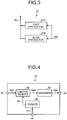
- FIG. 3 is a functional block diagram of the configuration of the instantaneous halting unit.
- the instantaneous halting unit 37 includes a fast protector 37A.
- This fast protector 37A is configured of an analog circuit for example as illustrated in FIG. 3 .
- the fast protector 37A controls all of the power amplifiers (not illustrated) of the AM wave generator 33 to be placed into an off state from an on-controlled state based on the anomaly discrimination value Vm and outputs as the anomaly detection signal Se a first control signal PC11 which places the AM wave generator 33 in a halting state.
- the instantaneous halting unit 37 further includes a slow protector 37B.
- This slow protector 37B is configured as a composite circuit of an analog circuit and a digital circuit as illustrated in FIG. 3 .
- the slow protector 37B outputs as the anomaly detection signal Se a second control signal PC12 which controls all of the power amplifiers (not illustrated) of the AM wave generator 33 to be placed in the off state from the on-controlled state based on the anomaly discrimination value Vm to place the AM wave generator 33 in the halting state.
- the fast protector 37A of the instantaneous halting unit 37 is configured of an analog circuit including an analog IC such as an operational amplifier or a comparator to output to the audio unit 32 the first control signal PC11 as the anomaly detection signal Se that controls all of the on-controlled power amplifiers of the AM wave generator to be placed in the off state when the anomaly discrimination value Vm output by the anomaly detector 36 is more than or equal to a first reference value which is a preset threshold value.
- the slow protector 37B of the instantaneous halting unit 37 is configured as a composite circuit of an analog circuit including an analog IC such as an operational amplifier or an A/D converter and a digital circuit such as a CPU, a CPLD, and an FPGA.
- the slow protector 37B outputs the second control signal PC12 as the anomaly detection signal Se to the audio unit 32.
- a pulse width of the first control signal PC11 output by the fast protector 37A is set to be longer than an operation delay time in the slow protector 37B configured as a composite circuit of an analog circuit and a digital circuit. This is to prevent the protection by the fast protector 37A from being cancelled before the protection by the slow protector 37B starts, that is, before the second control signal PC12 is output.
- the slow protector 37B restarts all of the power amplifiers (not illustrated) to place them in the on state again for a short period of time and recalculates the anomaly discrimination value Vm.
- the anomaly discrimination value Vm falls to or below the first reference value, the output of the anomaly detection signal Se is canceled.
- the slow protector 37B further has a function to increase or decrease the anomaly discrimination value Vm when the value vm output by the anomaly detector 36 is less than or equal to the first reference value and more than or equal to the second reference value which are preset threshold values.
- the AM wave output is not blocked during the increase or decrease operation and the anomaly detection signal Se is thus not output basically.
- the anomaly detection signal Se can be output to implement broadcast relay assistance processing.
- the broadcast relay assistance processing will be described later. In this case, for example a dynamic range controlling process may be added to add a sound quality improving method.
- the anomaly discrimination values Vm of the fast protector 37A and the slow protector 37B may differ, however, they can be deemed equivalent for the operation since the difference is attributable to different calculation results from the same source.
- FIG. 4 is a schematic block diagram of the configuration of the audio unit.
- the audio unit 32 generally includes a trigger 42, a control memory 44, and a shrinker 46.
- the trigger 42 receives the anomaly detection signal Se via an anomaly information input terminal 41 and outputs a control signal for the output control of the broadcast audio signal Sba based on the anomaly detection signal Se.
- the control memory 44 receives the broadcast audio signal Sba via an audio signal input terminal 43, encodes the broadcast audio signal Sba, and stores it as the broadcast audio data added with a time code representing a reproduction order.
- the control memory 44 further sequentially outputs the broadcast audio data during normalcy, calculates silent time upon occurrence of anomaly based on the control signal output by the trigger 42, and outputs silent time data corresponding to the silent time and the broadcast audio data Dba corresponding to the silent time data.
- the shrinker 46 adjusts actual reproduction time of the broadcast audio signal Sba corresponding to the broadcast audio data Dba based on the decoded broadcast audio data Dba and the silent time data for output from an audio signal output terminal 45.
- the broadcast audio signal generation device 21 of the medium wave radio broadcast system 10 generates broadcast audio signals Sba as audio signals for broadcasting and outputs them to the relay device 22.
- the relay device 22 relays the broadcast audio signals Sba generated by the broadcast audio signal generation device 21 to the audio signal input terminal 31 of the transmitter 23.
- the audio unit 32 of the transmitter 23 receives the broadcast audio signals Sba from the relay device 22 via the audio signal input terminal 31, adds a time code representing a reproduction order to the signals and stores them as broadcast audio data. In parallel with this, the audio unit 32 outputs, to the AM wave generator 33, the broadcast audio signals Sba in association with the time code.
- the AM wave generator 33 performs AM modulation of carrier waves based on the broadcast audio signals Sba output by the audio unit 32 to generate AM waves and outputs them to the pickup 35.
- the pickup 35 outputs the AM waves output by the AM wave generator 33 to the antenna matcher 24 via the AM wave output terminal 34. In parallel with this, the pickup 35 picks up AM waves for anomaly detection.
- the anomaly detector 36 calculates the anomaly discrimination value Vm based on the AM waves picked up by the pickup 35 and outputs the value to the instantaneous halting unit 37.
- the instantaneous halting unit 37 does not output the anomaly detection signal Se.
- the AM wave generator 33 thus continues to output AM waves and the antenna matcher 24 matches impedance between the output terminal of the transmitter 23 and the antenna 25.
- the antenna 25 emits high-frequency transmission signals to a space as radio waves for broadcasting.
- the broadcast audio signal generation device 21 of the medium wave radio broadcast system 10 generates the broadcast audio signals Sba as audio signals for broadcasting and outputs them to the relay device 22.
- the relay device 22 relays the broadcast audio signals Sba generated by the broadcast audio signal generation device 21 to the audio signal input terminal 31 of the transmitter 23.
- the audio unit 32 of the transmitter 23 receives the broadcast audio signals Sba from the relay device 22 via the audio signal input terminal 31, adds to the signals Sba a time code representing a reproduction order, and stores them as broadcast audio data. In parallel with this, the audio unit 32 outputs, to the AM wave generator 33, the broadcast audio signals Sba in association with the time code.
- the AM wave generator 33 performs AM modulation of carrier waves based on the broadcast audio signals Sba output by the audio unit 32 and thereby generates and outputs AM waves to the pickup 35.
- the pickup 35 outputs the AM waves output by the AM wave generator 33 to the antenna matcher 24 via the AM wave output terminal 34. In parallel with this, the pickup 35 picks up AM waves for anomaly detection.
- the anomaly detector 36 calculates the anomaly discrimination value Vm based on the AM waves picked up by the pickup 35 and outputs the anomaly detection signal Se to the instantaneous halting unit 37 based on the anomaly discrimination value Vm.
- the instantaneous halting unit 37 upon receipt of the anomaly detection signal Se, the instantaneous halting unit 37 outputs the anomaly detection signal Se to the audio unit 32 and controls the AM wave generator 33 to interrupt AM wave outputs for a certain period of time.
- the AM wave generator 33 stops outputting the AM waves and thus the transmission antenna 25 halts emitting the high-frequency transmission signals to a space as radio waves, thereby interrupting broadcasting.
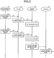
- FIG. 5 is a process sequence chart of the audio unit upon detection of anomaly.
- the trigger 42 of the audio unit 32 controls the output of the broadcast audio signals Sba based on the anomaly detection signal Se. More specifically, the trigger 42 of the audio unit 32 outputs, to the control memory 44 (step S12), the first control signal SC1 for setting a reproduction start point (rewinding point).
- the control memory 44 sets the reproduction start point (reproduction start time: rewinding point) (step S13).
- the trigger 42 of the audio unit 32 outputs, to the control memory 44, the second control signal SC2 for processing a silent part due to anomaly detection, in response to the cancellation of the anomaly detection signal Se (step S15).
- the control memory 44 then outputs, to the shrinker 46, broadcast audio data which, with no interruption of broadcasting, would otherwise have been broadcast during the calculated silent time and until the silent time elapses from the reproduction start point (reproduction start time) (step S17).
- the shrinker 46 outputs, to the AM wave generator 33, the broadcast audio signals Sba corresponding to the broadcast audio data based on the decoded broadcast audio data from the control memory 44 and the silent time data (step S18).
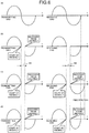
- FIG. 6 is an explanatory diagram of specific operations.
- FIG. 6(a) schematically presents reproduction states of the broadcast audio signals Sba at a transmitting end and a receiving end when no anomaly is detected, and occurrence of the same audio waveform.
- FIG. 6(b) schematically presents conventional reproduction states of broadcast audio signals Sba on a transmitting end and a receiving end upon detection of anomaly. It is seen from the drawing that the reproduced broadcast audio signals Sba is interrupted at the receiving end from occurrence of the anomaly to recovery from the anomaly at the transmitting end. Conventionally, sound is thus interrupted at the receiving end and transmitted contents are also interrupted.
- the broadcast audio signals Sba from output start time to output cancellation time of the anomaly detection signal Se are transmitted.
- the shrinker 46 can be configured to adjust the actual reproduction time of the broadcast audio signals Sba for output to the AM wave generator 33.
- FIG. 6(d) is an explanatory diagram of adjustment of the actual reproduction time of the broadcast audio signals Sba.
- the shrinker 46 here shortens only the reproduction time by so-called time stretching without changing the pitch of the broadcast sound, and reproduces the signals for a length of time obtained by subtracting the silent time from the original reproduction time.
- FIG. 7 is an explanatory diagram of the relation between a program broadcasting period and a commercial broadcasting period.
- a commercial broadcasting period TB2 continues with a program broadcasting period TB1 .
- broadcast program sound NS1 is broadcast sound which is originally scheduled to be broadcast in the silent period NS while broadcast program sound SS1 is broadcast sound which is originally scheduled to be broadcast in the broadcasting period TB1 after the silent period NS.
- the broadcast program sound NS1 and the broadcast program sound SS1 are together subjected to time stretching and thereby controlled to be completely broadcast within a broadcasting period SS.
- An actual program period thus falls within the original program period as illustrated in FIG. 7(c) , and is prevented from cutting into the commercial period.
- the broadcast program sound NS1 and the broadcast program sound SS1 are both subjected to time stretching in the above description; however, with a short silent period NS, the broadcast program sound NS1 and a part of the broadcast program sound SS1 can be subjected to time stretching.
- the part of the broadcast program sound SS1 can be a continuous part or discrete parts.
- a head of the broadcast program sound SS1 may be subjected to time stretching integrally with the broadcast program sound NS1.
- ends of the program broadcast sound NS1 and the broadcast program sound SS1 may be integrally subjected to time stretching.
- the respective multiple parts of the broadcast program sound NS1 and the broadcast program sound SS1 may be integrally subjected to time stretching.
- a part of the broadcast program sound NS1 can be deleted (usually a head part) and the remaining part of the broadcast program sound NS1 and the broadcast program sound SS1 can be subjected to the processing (time stretching) in the program period in the same manner.
- the reproduction start point coincides with anomaly detection timing, and hence does not always fall at a phonetically appropriate point. Specifically, it may come at the middle of a word (for example a reproduction start time of the "r" sound of the word “broadcast”) or during reproduction of one sound (for example during reproduction of the "e” sound of the word “speech"). In such a case, it is possible to extract the head of a word or the head of a sound by sound recognition, for example and transmit the broadcast audio data from time corresponding to a phonetically appropriate separating point prior to the reproduction start point.
- a word for example a reproduction start time of the "r" sound of the word "broadcast”
- reproduction of one sound for example during reproduction of the "e” sound of the word "speech”
- control memory 44 of the audio unit 32 outputs, to the AM wave generator 33, the broadcast audio signals Sba output within a period from the anomaly detection to the end of the anomaly detection.
- the AM wave generator 33 This allows the AM wave generator 33 to generate AM waves again by the AM modulation of carrier waves based on the broadcast audio signals Sba output by the audio unit 32, and to output them to the pickup 35.
- the pickup 35 outputs the AM waves output by the AM wave generator 33 to the antenna matcher 24 via the AM wave output terminal 34.
- the antenna matcher 24 matches impedance between the output terminal of the transmitter 23 and the antenna 25.
- the antenna 25 emits high-frequency transmission signals to a space as radio waves and continues to broadcast again.
- the suppression of missing information can inhibit a listener from being affected by the silent state, for example.
- the trigger 4 outputs the first control signal SC1 and the second control signal SC2 to the control memory 44 based on the anomaly detection signal Se from the instantaneous halting unit 37; however, the trigger 42 can be omitted and the control memory 44 can be configured to output and cancel the output of the anomaly detection signal Se, the first control signal SC1, and the second control signal SC2 in the same manner.
- the audio unit 32 of the transmitter 23 functions as the broadcast relay assistance device; however, the broadcast audio signal generation device 21 or the relay device 22 can be configured to have the same or like functions (functions of the trigger 42, the control memory 44, and the shrinker 46).
- the instantaneous halting unit 37 of the transmitter 23 is required to feed back the signals to the broadcast audio signal generation device 21 or the relay device 22.
- a pilot signal may be superimposed on the broadcast audio signal Sba.
- the pilot signal of a single tone may be used and added to a frequency other than audible frequencies (e.g. 7.5 kHz or more).
- the above descriptions have exemplified a configuration that a commercial broadcasting period is not subjected to anomaly handling.
- the above processing may not be performed, for example, to a broadcast period where the processing of broadcast sound may induce a copyright issue (e.g. music broadcasting period) or a broadcast period where processing to content is prohibited by law and content is required to be broadcast as it is (e.g. election broadcasting period).
- the broadcast relay assistance device of the present embodiment includes a control device such as a CPU and a memory device such as a read only memory (ROM) or a RAM and thus can have a hardware configuration using a general computer.
- a control device such as a CPU
- a memory device such as a read only memory (ROM) or a RAM
- a control program executed in the broadcast relay assistance device of the present embodiment can be stored and provided in an installable or executable file format on a computer-readable recording medium such as a CD-ROM, a flexible disc (FD), a CD-R, and a digital versatile disk (DVD).
- a computer-readable recording medium such as a CD-ROM, a flexible disc (FD), a CD-R, and a digital versatile disk (DVD).
- control program executed in the broadcast relay assistance device of the present embodiment may be stored in a computer connected to a network such as the Internet and provided by download via the network. Moreover, the control program executed in the broadcast relay assistance device of the present embodiment may be provided or distributed via a network such as the Internet.
- control program of the broadcast relay assistance device of the present embodiment may be incorporated into a ROM or the like in advance.
- the control program executed in the broadcast relay assistance device of the present embodiment has a module configuration including the aforementioned respective units or elements (memory, output unit, ).
- a CPU processor
- the memory, the output unit, ... are thus generated on the main memory device.
Landscapes
- Engineering & Computer Science (AREA)
- Signal Processing (AREA)
- Physics & Mathematics (AREA)
- Electromagnetism (AREA)
- Computer Networks & Wireless Communication (AREA)
- Radio Relay Systems (AREA)
- Transmitters (AREA)
Abstract
Description
- Embodiments of the present invention relate to a broadcast relay assistance device, and a control method and a control program for a broadcast relay assistance device.
- In medium wave radio broadcasting, broadcast audio signals (radio program) are produced in a studio with studio equipment and transmitted to a transmitting station with a transmitter via a relay device. In the transmitting station, AM waves are generated with the transmitter and sent to a certain broadcast service area.
- Meanwhile, transmitters adopt control technique for blocking AM wave outputs for a short period of time in case of occurrence of anomaly such as stroke of lightning and release thunder energy to the ground (grounding), for example.
- This is intended to prevent destruction of a transmitter (especially an amplifier) by the thunder energy. AM wave outputs are blocked for a short period of time for the purpose of blocking continuation of a load short circuit state (follow current) generated by the thunder energy.
- For example, Patent Literatures propose a technique to monitor a standing wave ratio (SWR) or discharge light and to block AM wave outputs for a short period of time.
-
- Patent Literature 1:
Japanese Patent Application Laid-open No. 9-162759 - Patent Literature 2:
Japanese Patent Application Laid-open No. 2013-191997 - As described above, conventional transmitters include a mechanism to block AM wave outputs for a short period of time upon occurrence of anomaly such as a stroke of lightning to protect the transmitters. However, short-time blocking of AM wave outputs may cause silent time in broadcast audio signals received by a receiver and thus interruption of sound for example, which may result in auditorily undesirable broadcasting.
- The present invention has been devised in consideration to the above. An object thereof is to provide a broadcast relay assistance device, and a control method and a control program for a broadcast relay assistance device which can mitigate the influence of a silent state on a listener even when the silent state occurs (short-time blocking of AM wave outputs) upon occurrence of anomaly.
- A memory of a broadcast relay assistance device of an embodiment stores broadcast audio data corresponding to input broadcast audio signals in a chronological order. Thereby, an output unit performs processing including reading, from the memory, based on an anomaly detection signal received from outside, the broadcast audio data corresponding to the broadcast audio signals that would have been broadcast during an anomaly detected period, and outputting the corresponding broadcast audio signals after an anomaly is resolved.
-
-
FIG. 1 is a schematic explanatory diagram of a configuration of a medium wave radio broadcast system of an embodiment. -
FIG. 2 is a schematic block diagram of a configuration of a transmitter. -
FIG. 3 is a functional block diagram of a configuration of an instantaneous halting unit. -
FIG. 4 is a schematic block diagram of a configuration of an audio unit. -
FIG. 5 is a processing sequence chart of the audio unit upon detection of anomaly. -
FIG. 6 is explanatory diagrams of specific operations. -
FIG. 7 is explanatory diagrams of relation between a program broadcasting period and a commercial broadcasting period. - Hereinafter, embodiments will be described with reference to the drawings.
-
FIG. 1 is a schematic explanatory diagram of the configuration of a medium wave radio broadcast system of an embodiment. - A medium wave
radio broadcast system 10 includes a broadcast audiosignal generation device 21 to generate a broadcast audio signal Sba that is audio signals for broadcasting, arelay device 22 to relay the broadcast audio signal Sba generated by the broadcast audiosignal generation device 21, atransmitter 23 to modulate the amplitude of the broadcast audio signal Sba relayed by therelay device 22 and to output it as transmission signal, an antenna matcher 24 to match impedance between an output terminal of thetransmitter 23 and anantenna 25, and theantenna 25 to emit the transmission signal being high frequency signal into a space as radio wave. -
FIG. 2 is a schematic block diagram of the configuration of a transmitter. - Herein, the
transmitter 23 functions as a broadcast relay assistance device. - The
transmitter 23 includes anaudio unit 32 which receives the broadcast audio signal Sba generated by the broadcast audiosignal generation device 21 via therelay device 22 and an audiosignal input terminal 31 and adds a time code representing a reproduction order to the broadcast audio signal Sba to store it as broadcast audio data Dba and output the broadcast audio signal in association with the time code, and anAM wave generator 33 having n power amplifiers (PAs) (not illustrated), to generate AM waves by AM modulation of carrier waves based on the broadcast audio signal output by theaudio unit 32 and to output the AM waves. - The
transmitter 23 includes apickup 35 to output the AM waves output from theAM wave generator 33 without change to the antenna matcher 24 via an AMwave output terminal 34 and to pick up AM waves for detection of anomaly such as a stroke of lightning when continuance of broadcasting may cause thetransmitter 23 to fail due to such anomaly, ananomaly detector 36 to detect an anomaly based on the AM waves picked up by thepickup 35 and to output an anomaly detection signal upon detection of the anomaly, and aninstantaneous halting unit 37 to, upon receipt of the anomaly detection signal, control theAM wave generator 33 to halt the output, and to notify theaudio unit 32 of output halting start upon the receipt of the anomaly detection signal and to notify theaudio unit 32 of output halting cancellation upon no receipt of the anomaly detection signal. - The
pickup 35 picks up an AM wave output from theAM wave generator 33 and measures a voltage value and a current value. Thepickup 35 outputs the measured voltage value and current value to theanomaly detector 36 as pick-up signals Sp. - The
anomaly detector 36 is configured as an analog circuit including an analog IC such as an operational amplifier which receives the voltage value and the current value (measured values) measured by thepickup 35 as the pick-up signals Sp. Theanomaly detector 36 performs addition, subtraction, division, smoothing, or correction on the measured voltage value and current value and outputs them to theinstantaneous halting unit 37 as an anomaly discrimination value Vm. - The
anomaly detector 36 can calculate the anomaly discrimination value Vm from the voltage value and a voltage value different in phase by n/2 from the voltage value. - The configuration of the
instantaneous halting unit 37 will be now described more specifically. - In order to block the
AM wave generator 33 from outputting AM waves for a certain period of time by controlling a power amplifier (not illustrated) of theAM wave generator 33 to be into an off state from an on-controlled state based on the anomaly discrimination value Vm, theinstantaneous halting unit 37 outputs the anomaly detection signal Se to theaudio unit 32. -
FIG. 3 is a functional block diagram of the configuration of the instantaneous halting unit. - The
instantaneous halting unit 37 includes afast protector 37A. Thisfast protector 37A is configured of an analog circuit for example as illustrated inFIG. 3 . Thefast protector 37A controls all of the power amplifiers (not illustrated) of theAM wave generator 33 to be placed into an off state from an on-controlled state based on the anomaly discrimination value Vm and outputs as the anomaly detection signal Se a first control signal PC11 which places theAM wave generator 33 in a halting state. - The
instantaneous halting unit 37 further includes aslow protector 37B. Thisslow protector 37B is configured as a composite circuit of an analog circuit and a digital circuit as illustrated inFIG. 3 . Theslow protector 37B outputs as the anomaly detection signal Se a second control signal PC12 which controls all of the power amplifiers (not illustrated) of theAM wave generator 33 to be placed in the off state from the on-controlled state based on the anomaly discrimination value Vm to place theAM wave generator 33 in the halting state. - More specifically, the
fast protector 37A of theinstantaneous halting unit 37 is configured of an analog circuit including an analog IC such as an operational amplifier or a comparator to output to theaudio unit 32 the first control signal PC11 as the anomaly detection signal Se that controls all of the on-controlled power amplifiers of the AM wave generator to be placed in the off state when the anomaly discrimination value Vm output by theanomaly detector 36 is more than or equal to a first reference value which is a preset threshold value. - The
slow protector 37B of theinstantaneous halting unit 37 is configured as a composite circuit of an analog circuit including an analog IC such as an operational amplifier or an A/D converter and a digital circuit such as a CPU, a CPLD, and an FPGA. Theslow protector 37B outputs the second control signal PC12 as the anomaly detection signal Se to theaudio unit 32. - In the above configuration, a pulse width of the first control signal PC11 output by the
fast protector 37A is set to be longer than an operation delay time in theslow protector 37B configured as a composite circuit of an analog circuit and a digital circuit. This is to prevent the protection by thefast protector 37A from being cancelled before the protection by theslow protector 37B starts, that is, before the second control signal PC12 is output. - In order to determine whether the anomalous state is resolved after the second control signal PC12 is output, the
slow protector 37B restarts all of the power amplifiers (not illustrated) to place them in the on state again for a short period of time and recalculates the anomaly discrimination value Vm. When the anomaly discrimination value Vm falls to or below the first reference value, the output of the anomaly detection signal Se is canceled. - The
slow protector 37B further has a function to increase or decrease the anomaly discrimination value Vm when the value vm output by theanomaly detector 36 is less than or equal to the first reference value and more than or equal to the second reference value which are preset threshold values. Note that the AM wave output is not blocked during the increase or decrease operation and the anomaly detection signal Se is thus not output basically. However, with a decrease in audio volume taken into account, the anomaly detection signal Se can be output to implement broadcast relay assistance processing. The broadcast relay assistance processing will be described later. In this case, for example a dynamic range controlling process may be added to add a sound quality improving method. The anomaly discrimination values Vm of thefast protector 37A and theslow protector 37B may differ, however, they can be deemed equivalent for the operation since the difference is attributable to different calculation results from the same source. -
FIG. 4 is a schematic block diagram of the configuration of the audio unit. - The
audio unit 32 generally includes atrigger 42, acontrol memory 44, and ashrinker 46. - In the above configuration, the
trigger 42 receives the anomaly detection signal Se via an anomalyinformation input terminal 41 and outputs a control signal for the output control of the broadcast audio signal Sba based on the anomaly detection signal Se. - The
control memory 44 receives the broadcast audio signal Sba via an audiosignal input terminal 43, encodes the broadcast audio signal Sba, and stores it as the broadcast audio data added with a time code representing a reproduction order. Thecontrol memory 44 further sequentially outputs the broadcast audio data during normalcy, calculates silent time upon occurrence of anomaly based on the control signal output by thetrigger 42, and outputs silent time data corresponding to the silent time and the broadcast audio data Dba corresponding to the silent time data. - The
shrinker 46 adjusts actual reproduction time of the broadcast audio signal Sba corresponding to the broadcast audio data Dba based on the decoded broadcast audio data Dba and the silent time data for output from an audiosignal output terminal 45. - Next, the operations of the embodiment will be described.
- First, normal operations will be described.
- The broadcast audio
signal generation device 21 of the medium waveradio broadcast system 10 generates broadcast audio signals Sba as audio signals for broadcasting and outputs them to therelay device 22. - The
relay device 22 relays the broadcast audio signals Sba generated by the broadcast audiosignal generation device 21 to the audiosignal input terminal 31 of thetransmitter 23. - The
audio unit 32 of thetransmitter 23 receives the broadcast audio signals Sba from therelay device 22 via the audiosignal input terminal 31, adds a time code representing a reproduction order to the signals and stores them as broadcast audio data. In parallel with this, theaudio unit 32 outputs, to theAM wave generator 33, the broadcast audio signals Sba in association with the time code. - The
AM wave generator 33 performs AM modulation of carrier waves based on the broadcast audio signals Sba output by theaudio unit 32 to generate AM waves and outputs them to thepickup 35. - The
pickup 35 outputs the AM waves output by theAM wave generator 33 to theantenna matcher 24 via the AMwave output terminal 34. In parallel with this, thepickup 35 picks up AM waves for anomaly detection. - Thereby, the
anomaly detector 36 calculates the anomaly discrimination value Vm based on the AM waves picked up by thepickup 35 and outputs the value to the instantaneous haltingunit 37. However, during normal time with no anomaly detected, the instantaneous haltingunit 37 does not output the anomaly detection signal Se. TheAM wave generator 33 thus continues to output AM waves and theantenna matcher 24 matches impedance between the output terminal of thetransmitter 23 and theantenna 25. Theantenna 25 emits high-frequency transmission signals to a space as radio waves for broadcasting. - Next, operations upon anomaly will be described.
- The broadcast audio
signal generation device 21 of the medium waveradio broadcast system 10 generates the broadcast audio signals Sba as audio signals for broadcasting and outputs them to therelay device 22. - The
relay device 22 relays the broadcast audio signals Sba generated by the broadcast audiosignal generation device 21 to the audiosignal input terminal 31 of thetransmitter 23. - The
audio unit 32 of thetransmitter 23 receives the broadcast audio signals Sba from therelay device 22 via the audiosignal input terminal 31, adds to the signals Sba a time code representing a reproduction order, and stores them as broadcast audio data. In parallel with this, theaudio unit 32 outputs, to theAM wave generator 33, the broadcast audio signals Sba in association with the time code. - The
AM wave generator 33 performs AM modulation of carrier waves based on the broadcast audio signals Sba output by theaudio unit 32 and thereby generates and outputs AM waves to thepickup 35. - The
pickup 35 outputs the AM waves output by theAM wave generator 33 to theantenna matcher 24 via the AMwave output terminal 34. In parallel with this, thepickup 35 picks up AM waves for anomaly detection. - Thereby, the
anomaly detector 36 calculates the anomaly discrimination value Vm based on the AM waves picked up by thepickup 35 and outputs the anomaly detection signal Se to the instantaneous haltingunit 37 based on the anomaly discrimination value Vm. - Thus, upon receipt of the anomaly detection signal Se, the instantaneous halting
unit 37 outputs the anomaly detection signal Se to theaudio unit 32 and controls theAM wave generator 33 to interrupt AM wave outputs for a certain period of time. - As a result, the
AM wave generator 33 stops outputting the AM waves and thus thetransmission antenna 25 halts emitting the high-frequency transmission signals to a space as radio waves, thereby interrupting broadcasting. -
FIG. 5 is a process sequence chart of the audio unit upon detection of anomaly. - When receiving the anomaly detection signal Se from the instantaneous halting unit 37 (step S11) via the anomaly
information input terminal 41, thetrigger 42 of theaudio unit 32 controls the output of the broadcast audio signals Sba based on the anomaly detection signal Se. More specifically, thetrigger 42 of theaudio unit 32 outputs, to the control memory 44 (step S12), the first control signal SC1 for setting a reproduction start point (rewinding point). - When receiving the first control signal SC1 from the
trigger 42, thecontrol memory 44 sets the reproduction start point (reproduction start time: rewinding point) (step S13). - Then, upon cancellation of the anomaly detection signal Se from the instantaneous halting unit 37 (step S14), the
trigger 42 of theaudio unit 32 outputs, to thecontrol memory 44, the second control signal SC2 for processing a silent part due to anomaly detection, in response to the cancellation of the anomaly detection signal Se (step S15). - When receiving the second control signal SC2, the
control memory 44 calculates a silent time (= reception time of the second control signal - reception time of the first control signal) caused by the interruption of broadcasting (step S16). - The
control memory 44 then outputs, to theshrinker 46, broadcast audio data which, with no interruption of broadcasting, would otherwise have been broadcast during the calculated silent time and until the silent time elapses from the reproduction start point (reproduction start time) (step S17). - Thereby, the
shrinker 46 outputs, to theAM wave generator 33, the broadcast audio signals Sba corresponding to the broadcast audio data based on the decoded broadcast audio data from thecontrol memory 44 and the silent time data (step S18). -
FIG. 6 is an explanatory diagram of specific operations. -
FIG. 6(a) schematically presents reproduction states of the broadcast audio signals Sba at a transmitting end and a receiving end when no anomaly is detected, and occurrence of the same audio waveform. - In contrast,
FIG. 6(b) schematically presents conventional reproduction states of broadcast audio signals Sba on a transmitting end and a receiving end upon detection of anomaly. It is seen from the drawing that the reproduced broadcast audio signals Sba is interrupted at the receiving end from occurrence of the anomaly to recovery from the anomaly at the transmitting end. Conventionally, sound is thus interrupted at the receiving end and transmitted contents are also interrupted. - In the present embodiment, as illustrated in
FIG. 6(c) , at time at which the output of the anomaly detection signal Se is canceled (anomaly recovery time), the broadcast audio signals Sba from output start time to output cancellation time of the anomaly detection signal Se are transmitted. - As a result, as illustrated in
FIG. 6(c) , although a silent interval occurs, broadcast sound is not interrupted after the transmission of the broadcast audio signals Sba, thereby implementing reliable information transmission. - Meanwhile, it is seen from the comparison between
FIG. 6(a) and FIG. 6(c) that, through the simple processing as above, broadcast time is extended by a length of time corresponding to the silent time. - Actual radio broadcasting, however, includes advertisements. It is thus undesirable that a program period cut into a commercial period.
- In view of this, the
shrinker 46 can be configured to adjust the actual reproduction time of the broadcast audio signals Sba for output to theAM wave generator 33. -
FIG. 6(d) is an explanatory diagram of adjustment of the actual reproduction time of the broadcast audio signals Sba. - The
shrinker 46 here shortens only the reproduction time by so-called time stretching without changing the pitch of the broadcast sound, and reproduces the signals for a length of time obtained by subtracting the silent time from the original reproduction time. -
FIG. 7 is an explanatory diagram of the relation between a program broadcasting period and a commercial broadcasting period. - As illustrated in
FIG. 7(a) , with no anomaly occurring, a commercial broadcasting period TB2 continues with a program broadcasting period TB1 . - In such a state, when anomaly occurs during the program broadcasting period TB1 as illustrated in
FIG. 7(b) , a silent time NS occurs in the program broadcasting period. - Herein, it is assumed that broadcast program sound NS1 is broadcast sound which is originally scheduled to be broadcast in the silent period NS while broadcast program sound SS1 is broadcast sound which is originally scheduled to be broadcast in the broadcasting period TB1 after the silent period NS.
- Continued normal broadcast under such circumstances results in missing broadcast program sound NS1. In the present embodiment, however, the broadcast program sound NS1 and the broadcast program sound SS1 are together subjected to time stretching and thereby controlled to be completely broadcast within a broadcasting period SS.
- An actual program period thus falls within the original program period as illustrated in
FIG. 7(c) , and is prevented from cutting into the commercial period. - The broadcast program sound NS1 and the broadcast program sound SS1 are both subjected to time stretching in the above description; however, with a short silent period NS, the broadcast program sound NS1 and a part of the broadcast program sound SS1 can be subjected to time stretching. In this case, the part of the broadcast program sound SS1 can be a continuous part or discrete parts.
- More specifically, a head of the broadcast program sound SS1 may be subjected to time stretching integrally with the broadcast program sound NS1. Alternatively, ends of the program broadcast sound NS1 and the broadcast program sound SS1 may be integrally subjected to time stretching. Alternatively, the respective multiple parts of the broadcast program sound NS1 and the broadcast program sound SS1 may be integrally subjected to time stretching.
- When the silent time period NS is long and time stretching of the program period causes too much auditory discomfort, a part of the broadcast program sound NS1 can be deleted (usually a head part) and the remaining part of the broadcast program sound NS1 and the broadcast program sound SS1 can be subjected to the processing (time stretching) in the program period in the same manner.
- In such a configuration, the reproduction start point coincides with anomaly detection timing, and hence does not always fall at a phonetically appropriate point. Specifically, it may come at the middle of a word (for example a reproduction start time of the "r" sound of the word "broadcast") or during reproduction of one sound (for example during reproduction of the "e" sound of the word "speech"). In such a case, it is possible to extract the head of a word or the head of a sound by sound recognition, for example and transmit the broadcast audio data from time corresponding to a phonetically appropriate separating point prior to the reproduction start point.
- As a result of the above, the
control memory 44 of theaudio unit 32 outputs, to theAM wave generator 33, the broadcast audio signals Sba output within a period from the anomaly detection to the end of the anomaly detection. - This allows the
AM wave generator 33 to generate AM waves again by the AM modulation of carrier waves based on the broadcast audio signals Sba output by theaudio unit 32, and to output them to thepickup 35. Thepickup 35 outputs the AM waves output by theAM wave generator 33 to theantenna matcher 24 via the AMwave output terminal 34. - The
antenna matcher 24 matches impedance between the output terminal of thetransmitter 23 and theantenna 25. Theantenna 25 emits high-frequency transmission signals to a space as radio waves and continues to broadcast again. - As described above, according to the present embodiment, even when a silent state occurs in the case of anomaly such as a stroke of lightning (AM wave output is blocked for a short period of time), the suppression of missing information can inhibit a listener from being affected by the silent state, for example.
- Next, modification of the embodiment will be described.
- In the above descriptions, the trigger 4 outputs the first control signal SC1 and the second control signal SC2 to the
control memory 44 based on the anomaly detection signal Se from the instantaneous haltingunit 37; however, thetrigger 42 can be omitted and thecontrol memory 44 can be configured to output and cancel the output of the anomaly detection signal Se, the first control signal SC1, and the second control signal SC2 in the same manner. - In the above descriptions, the
audio unit 32 of thetransmitter 23 functions as the broadcast relay assistance device; however, the broadcast audiosignal generation device 21 or therelay device 22 can be configured to have the same or like functions (functions of thetrigger 42, thecontrol memory 44, and the shrinker 46). In this case, the instantaneous haltingunit 37 of thetransmitter 23 is required to feed back the signals to the broadcast audiosignal generation device 21 or therelay device 22. - The above descriptions do not include how to discriminate the program broadcasting period and the commercial broadcasting period. For example, a pilot signal may be superimposed on the broadcast audio signal Sba. In this case, for example, the pilot signal of a single tone may be used and added to a frequency other than audible frequencies (e.g. 7.5 kHz or more).
- The above descriptions have exemplified a configuration that a commercial broadcasting period is not subjected to anomaly handling. However, the above processing may not be performed, for example, to a broadcast period where the processing of broadcast sound may induce a copyright issue (e.g. music broadcasting period) or a broadcast period where processing to content is prohibited by law and content is required to be broadcast as it is (e.g. election broadcasting period).
- The broadcast relay assistance device of the present embodiment includes a control device such as a CPU and a memory device such as a read only memory (ROM) or a RAM and thus can have a hardware configuration using a general computer.
- A control program executed in the broadcast relay assistance device of the present embodiment can be stored and provided in an installable or executable file format on a computer-readable recording medium such as a CD-ROM, a flexible disc (FD), a CD-R, and a digital versatile disk (DVD).
- Furthermore, the control program executed in the broadcast relay assistance device of the present embodiment may be stored in a computer connected to a network such as the Internet and provided by download via the network. Moreover, the control program executed in the broadcast relay assistance device of the present embodiment may be provided or distributed via a network such as the Internet.
- Furthermore, the control program of the broadcast relay assistance device of the present embodiment may be incorporated into a ROM or the like in advance.
- The control program executed in the broadcast relay assistance device of the present embodiment has a module configuration including the aforementioned respective units or elements (memory, output unit, ...). As actual hardware, a CPU (processor) reads the control program from the recording medium and executes the control program, thereby allowing the respective units or elements to be loaded on a main memory device. The memory, the output unit, ... are thus generated on the main memory device.
- While certain embodiments have been described, these embodiments have been presented by way of example only, and are not intended to limit the scope of the inventions. Indeed, the novel embodiments described herein may be embodied in a variety of other forms; furthermore, various omissions, substitutions and changes in the form of the embodiments described herein may be made without departing from the spirit of the inventions. The accompanying claims and their equivalents are intended to cover such forms or modifications as would fall within the scope and spirit of the inventions.
Claims (9)
- A broadcast relay assistance device, comprising:a memory that stores broadcast audio data corresponding to input broadcast audio signals in a chronological order; andan output unit that performs processing including reading, from the memory, based on an anomaly detection signal received from outside, the broadcast audio data corresponding to the broadcast audio signals that would have been broadcast during an anomaly detected period, and outputting the corresponding broadcast audio signals after an anomaly is resolved.
- The broadcast relay assistance device according to claim 1,
wherein the output unit performs the processing by also including the broadcast audio data corresponding to the broadcast audio signals that would have been broadcast during a period subsequent to the anomaly detected period. - The broadcast relay assistance device according to claim 1,
wherein the output unit performs the processing including the broadcast audio data corresponding to the broadcast audio signals broadcast immediately before the anomaly detected period. - The broadcast relay assistance device according to claim 1,
wherein the output unit completes outputting of all the broadcast audio signals read from the memory corresponding to the broadcast audio data, by timing at which with no detection of anomaly, the outputting would have completed. - The broadcast relay assistance device according to claim 4,
wherein the output unit completes the outputting by time stretching of the broadcast audio signals by the timing at which with no detection of anomaly, the outputting would have completed. - The broadcast relay assistance device according to claim 1,
wherein, of the broadcast audio signals, the broadcast audio signals to be processed by the output unit are distinguishable, and
the output unit performs the processing only on the broadcast audio signals to be processed. - The broadcast relay assistance device according to claim 6,
wherein the broadcast audio signals include a superposed pilot signal, and
the output unit distinguishes the broadcast audio signals to be processed based on the pilot signal. - A control method for a broadcast relay assistance device, the method executed in a broadcast relay assistance device comprising a memory to store broadcast audio data, the method comprising:storing, in a chronological order, broadcast audio data corresponding to broadcast audio signals input to the memory; andreading, from the memory, based on an anomaly detection signal received from outside, the broadcast audio data corresponding to the broadcast audio signals that would have been broadcast during an anomaly detected period , and outputting the corresponding broadcast audio signals after an anomaly is resolved.
- A control program for causing a computer to control a broadcast relay assistance device, the program executed in a broadcast relay assistance device comprising a memory to store broadcast audio data,
the control program for causing the computer to function as:a memory controller that stores, in a chronological order, broadcast audio data corresponding to broadcast audio signals input to the memory; andan output unit that reads, from the memory, based on the anomaly detection signal received from outside, the broadcast audio data corresponding to the broadcast audio signals that would have been broadcast during an anomaly detected period , outputs the corresponding broadcast audio signals after an anomaly is resolved.
Applications Claiming Priority (2)
| Application Number | Priority Date | Filing Date | Title |
|---|---|---|---|
| JP2014089566A JP5937134B2 (en) | 2014-04-23 | 2014-04-23 | Broadcast continuation support apparatus, control method and control program for broadcast continuation support apparatus |
| PCT/JP2014/084634 WO2015162831A1 (en) | 2014-04-23 | 2014-12-26 | Broadcast relay assistance device, broadcast relay assistance device control method and control program |
Publications (3)
| Publication Number | Publication Date |
|---|---|
| EP3136629A1 true EP3136629A1 (en) | 2017-03-01 |
| EP3136629A4 EP3136629A4 (en) | 2017-09-27 |
| EP3136629B1 EP3136629B1 (en) | 2020-01-22 |
Family
ID=54332015
Family Applications (1)
| Application Number | Title | Priority Date | Filing Date |
|---|---|---|---|
| EP14889887.7A Active EP3136629B1 (en) | 2014-04-23 | 2014-12-26 | Broadcast relay assistance device, broadcast relay assistance device control method and control program |
Country Status (5)
| Country | Link |
|---|---|
| US (1) | US10250344B2 (en) |
| EP (1) | EP3136629B1 (en) |
| JP (1) | JP5937134B2 (en) |
| CN (1) | CN106233645B (en) |
| WO (1) | WO2015162831A1 (en) |
Families Citing this family (1)
| Publication number | Priority date | Publication date | Assignee | Title |
|---|---|---|---|---|
| EP4084366A1 (en) * | 2021-04-26 | 2022-11-02 | Aptiv Technologies Limited | Method for testing in-vehicle radio broadcast receiver device |
Family Cites Families (16)
| Publication number | Priority date | Publication date | Assignee | Title |
|---|---|---|---|---|
| JPH09162759A (en) | 1995-12-11 | 1997-06-20 | Nec Eng Ltd | Protection circuit for medium radio wave broadcast equipment |
| US6961513B2 (en) * | 1999-12-16 | 2005-11-01 | Sony Corporation | Audio signal processing method, audio signal processing apparatus, Hi-Fi video apparatus, digital video apparatus and 8 mm video apparatus |
| JP2001177803A (en) * | 1999-12-16 | 2001-06-29 | Sony Corp | Audio signal processing method, audio signal reproducing device, hi-fi video device, digital video device, 8 mm video device |
| JP2004040604A (en) * | 2002-07-05 | 2004-02-05 | Nippon Hoso Kyokai <Nhk> | Broadcast communication content sending method, broadcast communication content sending device, broadcast communication content sending program and broadcast communication content receiving method, broadcast communication content receiving device, broadcast communication content receiving program |
| KR20050121067A (en) * | 2004-06-21 | 2005-12-26 | 삼성전자주식회사 | Wireless communication system using wireless channel and wireless communication method thereof |
| US7511467B2 (en) * | 2005-10-14 | 2009-03-31 | Nokia Corporation | Detection of lightning |
| JP2007243906A (en) * | 2006-02-07 | 2007-09-20 | Toshiba Corp | Broadcast equipment for closed space |
| JP5130734B2 (en) * | 2007-02-15 | 2013-01-30 | ソニー株式会社 | Information processing apparatus, information processing method, and computer program |
| JP5631672B2 (en) | 2010-09-08 | 2014-11-26 | 株式会社東芝 | Booklet page turning device |
| KR101337116B1 (en) | 2010-09-08 | 2013-12-05 | 가부시끼가이샤 도시바 | Apparatus for turning page of booklet |
| JP5342033B2 (en) * | 2012-03-13 | 2013-11-13 | 株式会社東芝 | Digital amplitude modulation device and control method of digital amplitude modulation device |
| US8935581B2 (en) * | 2012-04-19 | 2015-01-13 | Netflix, Inc. | Upstream fault detection |
| KR20130123713A (en) * | 2012-05-03 | 2013-11-13 | 현대모비스 주식회사 | Method removing pop-noise |
| JP5575189B2 (en) * | 2012-07-04 | 2014-08-20 | 株式会社東芝 | Digital amplitude modulation device and control method of digital amplitude modulation device |
| JP6180780B2 (en) * | 2013-04-22 | 2017-08-16 | 三菱電機ビルテクノサービス株式会社 | Video data transmission apparatus and video data management system |
| CN103986833A (en) * | 2014-05-22 | 2014-08-13 | 小米科技有限责任公司 | Abnormal condition monitoring method and device |
-
2014
- 2014-04-23 JP JP2014089566A patent/JP5937134B2/en not_active Expired - Fee Related
- 2014-12-26 WO PCT/JP2014/084634 patent/WO2015162831A1/en not_active Ceased
- 2014-12-26 EP EP14889887.7A patent/EP3136629B1/en active Active
- 2014-12-26 US US15/305,508 patent/US10250344B2/en not_active Expired - Fee Related
- 2014-12-26 CN CN201480078113.1A patent/CN106233645B/en not_active Expired - Fee Related
Also Published As
| Publication number | Publication date |
|---|---|
| JP5937134B2 (en) | 2016-06-22 |
| US20170041089A1 (en) | 2017-02-09 |
| CN106233645B (en) | 2020-01-31 |
| CN106233645A (en) | 2016-12-14 |
| US10250344B2 (en) | 2019-04-02 |
| EP3136629A4 (en) | 2017-09-27 |
| EP3136629B1 (en) | 2020-01-22 |
| JP2015210288A (en) | 2015-11-24 |
| WO2015162831A1 (en) | 2015-10-29 |
Similar Documents
| Publication | Publication Date | Title |
|---|---|---|
| CN109640223B (en) | Howling suppression method and device, sound and sound amplification system | |
| EP3748635B1 (en) | Acoustic device and acoustic processing method | |
| US10250344B2 (en) | Broadcast of audio data based on input broadcast signals stored during a detected anomaly period by lightning energy | |
| US10320432B2 (en) | Appliance for receiving radio frequency signals, usable in particular for the management of uplink signals | |
| MX2014009225A (en) | Method for performing announcements in a means of transport. | |
| JP5575189B2 (en) | Digital amplitude modulation device and control method of digital amplitude modulation device | |
| JP2006254345A (en) | Transmitter power amplifier | |
| US8879583B1 (en) | Radio frequency conditioning unit | |
| US20190296782A1 (en) | Receiver and non-transitory computer readable medium storing program | |
| US12039964B2 (en) | Audio processing system signal-level based temporal masking | |
| JP6419429B2 (en) | Digital amplitude modulator | |
| JP2019184475A (en) | Discharge accident detection structure | |
| JP2007325225A (en) | Noise detection device and am broadcast receiver | |
| JP2013012973A (en) | Digital amplifier, method of controlling digital amplifier, and program | |
| JP4916477B2 (en) | Audio amplifier | |
| JP2001313567A (en) | High power selective signal attenuator and attenuation method | |
| JP2014519745A (en) | Reduce distortion | |
| JP4613138B2 (en) | Relay device | |
| JP7090801B2 (en) | Transmitter, receiver, and wireless microphone system | |
| JP7150536B2 (en) | Impedance adjustment method and impedance adjustment program | |
| KR101106283B1 (en) | Adaptive tone jammer removal device and method | |
| JP4606864B2 (en) | AGC circuit and control method | |
| JP4690803B2 (en) | Broadcast relay equipment | |
| US20240356654A1 (en) | Signal amplification method and optical receiving apparatus | |
| US20180159481A1 (en) | Low-noise amplification device, method, and attenuation adjustment program |
Legal Events
| Date | Code | Title | Description |
|---|---|---|---|
| STAA | Information on the status of an ep patent application or granted ep patent |
Free format text: STATUS: THE INTERNATIONAL PUBLICATION HAS BEEN MADE |
|
| PUAI | Public reference made under article 153(3) epc to a published international application that has entered the european phase |
Free format text: ORIGINAL CODE: 0009012 |
|
| STAA | Information on the status of an ep patent application or granted ep patent |
Free format text: STATUS: REQUEST FOR EXAMINATION WAS MADE |
|
| 17P | Request for examination filed |
Effective date: 20161018 |
|
| AK | Designated contracting states |
Kind code of ref document: A1 Designated state(s): AL AT BE BG CH CY CZ DE DK EE ES FI FR GB GR HR HU IE IS IT LI LT LU LV MC MK MT NL NO PL PT RO RS SE SI SK SM TR |
|
| AX | Request for extension of the european patent |
Extension state: BA ME |
|
| DAX | Request for extension of the european patent (deleted) | ||
| A4 | Supplementary search report drawn up and despatched |
Effective date: 20170828 |
|
| RIC1 | Information provided on ipc code assigned before grant |
Ipc: G10L 21/057 20130101ALI20170822BHEP Ipc: H04H 20/12 20080101AFI20170822BHEP Ipc: G10L 19/005 20130101ALI20170822BHEP |
|
| STAA | Information on the status of an ep patent application or granted ep patent |
Free format text: STATUS: EXAMINATION IS IN PROGRESS |
|
| 17Q | First examination report despatched |
Effective date: 20180924 |
|
| GRAP | Despatch of communication of intention to grant a patent |
Free format text: ORIGINAL CODE: EPIDOSNIGR1 |
|
| STAA | Information on the status of an ep patent application or granted ep patent |
Free format text: STATUS: GRANT OF PATENT IS INTENDED |
|
| INTG | Intention to grant announced |
Effective date: 20190913 |
|
| GRAS | Grant fee paid |
Free format text: ORIGINAL CODE: EPIDOSNIGR3 |
|
| GRAA | (expected) grant |
Free format text: ORIGINAL CODE: 0009210 |
|
| STAA | Information on the status of an ep patent application or granted ep patent |
Free format text: STATUS: THE PATENT HAS BEEN GRANTED |
|
| REG | Reference to a national code |
Ref country code: DE Ref legal event code: R082 Ref document number: 602014060514 Country of ref document: DE Representative=s name: HOFFMANN - EITLE PATENT- UND RECHTSANWAELTE PA, DE |
|
| AK | Designated contracting states |
Kind code of ref document: B1 Designated state(s): AL AT BE BG CH CY CZ DE DK EE ES FI FR GB GR HR HU IE IS IT LI LT LU LV MC MK MT NL NO PL PT RO RS SE SI SK SM TR |
|
| REG | Reference to a national code |
Ref country code: GB Ref legal event code: FG4D |
|
| REG | Reference to a national code |
Ref country code: CH Ref legal event code: EP |
|
| REG | Reference to a national code |
Ref country code: AT Ref legal event code: REF Ref document number: 1227619 Country of ref document: AT Kind code of ref document: T Effective date: 20200215 |
|
| REG | Reference to a national code |
Ref country code: IE Ref legal event code: FG4D |
|
| REG | Reference to a national code |
Ref country code: DE Ref legal event code: R096 Ref document number: 602014060514 Country of ref document: DE |
|
| REG | Reference to a national code |
Ref country code: NL Ref legal event code: MP Effective date: 20200122 |
|
| REG | Reference to a national code |
Ref country code: LT Ref legal event code: MG4D |
|
| PG25 | Lapsed in a contracting state [announced via postgrant information from national office to epo] |
Ref country code: NL Free format text: LAPSE BECAUSE OF FAILURE TO SUBMIT A TRANSLATION OF THE DESCRIPTION OR TO PAY THE FEE WITHIN THE PRESCRIBED TIME-LIMIT Effective date: 20200122 Ref country code: NO Free format text: LAPSE BECAUSE OF FAILURE TO SUBMIT A TRANSLATION OF THE DESCRIPTION OR TO PAY THE FEE WITHIN THE PRESCRIBED TIME-LIMIT Effective date: 20200422 Ref country code: RS Free format text: LAPSE BECAUSE OF FAILURE TO SUBMIT A TRANSLATION OF THE DESCRIPTION OR TO PAY THE FEE WITHIN THE PRESCRIBED TIME-LIMIT Effective date: 20200122 Ref country code: FI Free format text: LAPSE BECAUSE OF FAILURE TO SUBMIT A TRANSLATION OF THE DESCRIPTION OR TO PAY THE FEE WITHIN THE PRESCRIBED TIME-LIMIT Effective date: 20200122 Ref country code: PT Free format text: LAPSE BECAUSE OF FAILURE TO SUBMIT A TRANSLATION OF THE DESCRIPTION OR TO PAY THE FEE WITHIN THE PRESCRIBED TIME-LIMIT Effective date: 20200614 |
|
| PG25 | Lapsed in a contracting state [announced via postgrant information from national office to epo] |
Ref country code: LV Free format text: LAPSE BECAUSE OF FAILURE TO SUBMIT A TRANSLATION OF THE DESCRIPTION OR TO PAY THE FEE WITHIN THE PRESCRIBED TIME-LIMIT Effective date: 20200122 Ref country code: SE Free format text: LAPSE BECAUSE OF FAILURE TO SUBMIT A TRANSLATION OF THE DESCRIPTION OR TO PAY THE FEE WITHIN THE PRESCRIBED TIME-LIMIT Effective date: 20200122 Ref country code: IS Free format text: LAPSE BECAUSE OF FAILURE TO SUBMIT A TRANSLATION OF THE DESCRIPTION OR TO PAY THE FEE WITHIN THE PRESCRIBED TIME-LIMIT Effective date: 20200522 Ref country code: GR Free format text: LAPSE BECAUSE OF FAILURE TO SUBMIT A TRANSLATION OF THE DESCRIPTION OR TO PAY THE FEE WITHIN THE PRESCRIBED TIME-LIMIT Effective date: 20200423 Ref country code: BG Free format text: LAPSE BECAUSE OF FAILURE TO SUBMIT A TRANSLATION OF THE DESCRIPTION OR TO PAY THE FEE WITHIN THE PRESCRIBED TIME-LIMIT Effective date: 20200422 Ref country code: HR Free format text: LAPSE BECAUSE OF FAILURE TO SUBMIT A TRANSLATION OF THE DESCRIPTION OR TO PAY THE FEE WITHIN THE PRESCRIBED TIME-LIMIT Effective date: 20200122 |
|
| REG | Reference to a national code |
Ref country code: DE Ref legal event code: R097 Ref document number: 602014060514 Country of ref document: DE |
|
| PG25 | Lapsed in a contracting state [announced via postgrant information from national office to epo] |
Ref country code: SM Free format text: LAPSE BECAUSE OF FAILURE TO SUBMIT A TRANSLATION OF THE DESCRIPTION OR TO PAY THE FEE WITHIN THE PRESCRIBED TIME-LIMIT Effective date: 20200122 Ref country code: DK Free format text: LAPSE BECAUSE OF FAILURE TO SUBMIT A TRANSLATION OF THE DESCRIPTION OR TO PAY THE FEE WITHIN THE PRESCRIBED TIME-LIMIT Effective date: 20200122 Ref country code: LT Free format text: LAPSE BECAUSE OF FAILURE TO SUBMIT A TRANSLATION OF THE DESCRIPTION OR TO PAY THE FEE WITHIN THE PRESCRIBED TIME-LIMIT Effective date: 20200122 Ref country code: EE Free format text: LAPSE BECAUSE OF FAILURE TO SUBMIT A TRANSLATION OF THE DESCRIPTION OR TO PAY THE FEE WITHIN THE PRESCRIBED TIME-LIMIT Effective date: 20200122 Ref country code: ES Free format text: LAPSE BECAUSE OF FAILURE TO SUBMIT A TRANSLATION OF THE DESCRIPTION OR TO PAY THE FEE WITHIN THE PRESCRIBED TIME-LIMIT Effective date: 20200122 Ref country code: RO Free format text: LAPSE BECAUSE OF FAILURE TO SUBMIT A TRANSLATION OF THE DESCRIPTION OR TO PAY THE FEE WITHIN THE PRESCRIBED TIME-LIMIT Effective date: 20200122 Ref country code: SK Free format text: LAPSE BECAUSE OF FAILURE TO SUBMIT A TRANSLATION OF THE DESCRIPTION OR TO PAY THE FEE WITHIN THE PRESCRIBED TIME-LIMIT Effective date: 20200122 Ref country code: CZ Free format text: LAPSE BECAUSE OF FAILURE TO SUBMIT A TRANSLATION OF THE DESCRIPTION OR TO PAY THE FEE WITHIN THE PRESCRIBED TIME-LIMIT Effective date: 20200122 |
|
| REG | Reference to a national code |
Ref country code: AT Ref legal event code: MK05 Ref document number: 1227619 Country of ref document: AT Kind code of ref document: T Effective date: 20200122 |
|
| PLBE | No opposition filed within time limit |
Free format text: ORIGINAL CODE: 0009261 |
|
| STAA | Information on the status of an ep patent application or granted ep patent |
Free format text: STATUS: NO OPPOSITION FILED WITHIN TIME LIMIT |
|
| 26N | No opposition filed |
Effective date: 20201023 |
|
| PG25 | Lapsed in a contracting state [announced via postgrant information from national office to epo] |
Ref country code: IT Free format text: LAPSE BECAUSE OF FAILURE TO SUBMIT A TRANSLATION OF THE DESCRIPTION OR TO PAY THE FEE WITHIN THE PRESCRIBED TIME-LIMIT Effective date: 20200122 Ref country code: AT Free format text: LAPSE BECAUSE OF FAILURE TO SUBMIT A TRANSLATION OF THE DESCRIPTION OR TO PAY THE FEE WITHIN THE PRESCRIBED TIME-LIMIT Effective date: 20200122 |
|
| PGFP | Annual fee paid to national office [announced via postgrant information from national office to epo] |
Ref country code: GB Payment date: 20201217 Year of fee payment: 7 Ref country code: DE Payment date: 20201216 Year of fee payment: 7 Ref country code: FR Payment date: 20201112 Year of fee payment: 7 |
|
| PG25 | Lapsed in a contracting state [announced via postgrant information from national office to epo] |
Ref country code: SI Free format text: LAPSE BECAUSE OF FAILURE TO SUBMIT A TRANSLATION OF THE DESCRIPTION OR TO PAY THE FEE WITHIN THE PRESCRIBED TIME-LIMIT Effective date: 20200122 Ref country code: PL Free format text: LAPSE BECAUSE OF FAILURE TO SUBMIT A TRANSLATION OF THE DESCRIPTION OR TO PAY THE FEE WITHIN THE PRESCRIBED TIME-LIMIT Effective date: 20200122 |
|
| REG | Reference to a national code |
Ref country code: CH Ref legal event code: PL |
|
| PG25 | Lapsed in a contracting state [announced via postgrant information from national office to epo] |
Ref country code: MC Free format text: LAPSE BECAUSE OF FAILURE TO SUBMIT A TRANSLATION OF THE DESCRIPTION OR TO PAY THE FEE WITHIN THE PRESCRIBED TIME-LIMIT Effective date: 20200122 |
|
| REG | Reference to a national code |
Ref country code: BE Ref legal event code: MM Effective date: 20201231 |
|
| PG25 | Lapsed in a contracting state [announced via postgrant information from national office to epo] |
Ref country code: IE Free format text: LAPSE BECAUSE OF NON-PAYMENT OF DUE FEES Effective date: 20201226 Ref country code: LU Free format text: LAPSE BECAUSE OF NON-PAYMENT OF DUE FEES Effective date: 20201226 |
|
| PG25 | Lapsed in a contracting state [announced via postgrant information from national office to epo] |
Ref country code: LI Free format text: LAPSE BECAUSE OF NON-PAYMENT OF DUE FEES Effective date: 20201231 Ref country code: CH Free format text: LAPSE BECAUSE OF NON-PAYMENT OF DUE FEES Effective date: 20201231 |
|
| PG25 | Lapsed in a contracting state [announced via postgrant information from national office to epo] |
Ref country code: TR Free format text: LAPSE BECAUSE OF FAILURE TO SUBMIT A TRANSLATION OF THE DESCRIPTION OR TO PAY THE FEE WITHIN THE PRESCRIBED TIME-LIMIT Effective date: 20200122 Ref country code: MT Free format text: LAPSE BECAUSE OF FAILURE TO SUBMIT A TRANSLATION OF THE DESCRIPTION OR TO PAY THE FEE WITHIN THE PRESCRIBED TIME-LIMIT Effective date: 20200122 Ref country code: CY Free format text: LAPSE BECAUSE OF FAILURE TO SUBMIT A TRANSLATION OF THE DESCRIPTION OR TO PAY THE FEE WITHIN THE PRESCRIBED TIME-LIMIT Effective date: 20200122 |
|
| PG25 | Lapsed in a contracting state [announced via postgrant information from national office to epo] |
Ref country code: MK Free format text: LAPSE BECAUSE OF FAILURE TO SUBMIT A TRANSLATION OF THE DESCRIPTION OR TO PAY THE FEE WITHIN THE PRESCRIBED TIME-LIMIT Effective date: 20200122 Ref country code: AL Free format text: LAPSE BECAUSE OF FAILURE TO SUBMIT A TRANSLATION OF THE DESCRIPTION OR TO PAY THE FEE WITHIN THE PRESCRIBED TIME-LIMIT Effective date: 20200122 |
|
| REG | Reference to a national code |
Ref country code: DE Ref legal event code: R119 Ref document number: 602014060514 Country of ref document: DE |
|
| PG25 | Lapsed in a contracting state [announced via postgrant information from national office to epo] |
Ref country code: BE Free format text: LAPSE BECAUSE OF NON-PAYMENT OF DUE FEES Effective date: 20201231 |
|
| GBPC | Gb: european patent ceased through non-payment of renewal fee |
Effective date: 20211226 |
|
| PG25 | Lapsed in a contracting state [announced via postgrant information from national office to epo] |
Ref country code: GB Free format text: LAPSE BECAUSE OF NON-PAYMENT OF DUE FEES Effective date: 20211226 Ref country code: DE Free format text: LAPSE BECAUSE OF NON-PAYMENT OF DUE FEES Effective date: 20220701 |
|
| PG25 | Lapsed in a contracting state [announced via postgrant information from national office to epo] |
Ref country code: FR Free format text: LAPSE BECAUSE OF NON-PAYMENT OF DUE FEES Effective date: 20211231 |