EP3136533A1 - Control method and control device - Google Patents
Control method and control device Download PDFInfo
- Publication number
- EP3136533A1 EP3136533A1 EP15783548.9A EP15783548A EP3136533A1 EP 3136533 A1 EP3136533 A1 EP 3136533A1 EP 15783548 A EP15783548 A EP 15783548A EP 3136533 A1 EP3136533 A1 EP 3136533A1
- Authority
- EP
- European Patent Office
- Prior art keywords
- electric energy
- value
- discharge
- storage battery
- charge
- Prior art date
- Legal status (The legal status is an assumption and is not a legal conclusion. Google has not performed a legal analysis and makes no representation as to the accuracy of the status listed.)
- Granted
Links
Images



Classifications
-
- H—ELECTRICITY
- H02—GENERATION; CONVERSION OR DISTRIBUTION OF ELECTRIC POWER
- H02J—ELECTRIC POWER NETWORKS; CIRCUIT ARRANGEMENTS OR SYSTEMS FOR SUPPLYING OR DISTRIBUTING ELECTRIC POWER; SYSTEMS FOR STORING ELECTRIC ENERGY
- H02J3/00—Circuit arrangements for AC mains or AC distribution networks
- H02J3/28—Arrangements for balancing of the load in networks by storage of energy
- H02J3/32—Arrangements for balancing of the load in networks by storage of energy using batteries or super capacitors with converting means
-
- H—ELECTRICITY
- H02—GENERATION; CONVERSION OR DISTRIBUTION OF ELECTRIC POWER
- H02J—ELECTRIC POWER NETWORKS; CIRCUIT ARRANGEMENTS OR SYSTEMS FOR SUPPLYING OR DISTRIBUTING ELECTRIC POWER; SYSTEMS FOR STORING ELECTRIC ENERGY
- H02J13/00—Circuit arrangements for providing remote monitoring or remote control of equipment in a power distribution network
-
- H—ELECTRICITY
- H02—GENERATION; CONVERSION OR DISTRIBUTION OF ELECTRIC POWER
- H02J—ELECTRIC POWER NETWORKS; CIRCUIT ARRANGEMENTS OR SYSTEMS FOR SUPPLYING OR DISTRIBUTING ELECTRIC POWER; SYSTEMS FOR STORING ELECTRIC ENERGY
- H02J3/00—Circuit arrangements for AC mains or AC distribution networks
-
- H—ELECTRICITY
- H02—GENERATION; CONVERSION OR DISTRIBUTION OF ELECTRIC POWER
- H02J—ELECTRIC POWER NETWORKS; CIRCUIT ARRANGEMENTS OR SYSTEMS FOR SUPPLYING OR DISTRIBUTING ELECTRIC POWER; SYSTEMS FOR STORING ELECTRIC ENERGY
- H02J3/00—Circuit arrangements for AC mains or AC distribution networks
- H02J3/38—Arrangements for feeding a single network from two or more generators or sources in parallel; Arrangements for feeding already energised networks from additional generators or sources in parallel
-
- H—ELECTRICITY
- H02—GENERATION; CONVERSION OR DISTRIBUTION OF ELECTRIC POWER
- H02J—ELECTRIC POWER NETWORKS; CIRCUIT ARRANGEMENTS OR SYSTEMS FOR SUPPLYING OR DISTRIBUTING ELECTRIC POWER; SYSTEMS FOR STORING ELECTRIC ENERGY
- H02J7/00—Circuit arrangements for charging or discharging batteries or for supplying loads from batteries
- H02J7/865—Battery or charger load switching, e.g. concurrent charging and load supply
-
- H—ELECTRICITY
- H02—GENERATION; CONVERSION OR DISTRIBUTION OF ELECTRIC POWER
- H02J—ELECTRIC POWER NETWORKS; CIRCUIT ARRANGEMENTS OR SYSTEMS FOR SUPPLYING OR DISTRIBUTING ELECTRIC POWER; SYSTEMS FOR STORING ELECTRIC ENERGY
- H02J9/00—Circuit arrangements for emergency or stand-by power supply, e.g. for emergency lighting
-
- H—ELECTRICITY
- H02—GENERATION; CONVERSION OR DISTRIBUTION OF ELECTRIC POWER
- H02M—APPARATUS FOR CONVERSION BETWEEN AC AND AC, BETWEEN AC AND DC, OR BETWEEN DC AND DC, AND FOR USE WITH MAINS OR SIMILAR POWER SUPPLY SYSTEMS; CONVERSION OF DC OR AC INPUT POWER INTO SURGE OUTPUT POWER; CONTROL OR REGULATION THEREOF
- H02M7/00—Conversion of AC power input into DC power output; Conversion of DC power input into AC power output
- H02M7/66—Conversion of AC power input into DC power output; Conversion of DC power input into AC power output with possibility of reversal
- H02M7/68—Conversion of AC power input into DC power output; Conversion of DC power input into AC power output with possibility of reversal by static converters
Definitions
- the present disclosure relates to a control method and a control device for a storage battery provided in a consumer site that receives its electric power supply from a system.
- electric power supply systems including storage batteries interconnected to commercial electric power systems (hereinafter, simply called the systems) to store electric power supplied from the systems for later use.
- Such electric power supply systems may be provided in households, commercial and industrial facilities, and others to store, in the storage batteries, electric power purchased from the electric power systems during a certain time period, such as midnight, when the cost of electric power is relatively low and to supply the electric power to electric power loads located in the households or premises by discharging the storage batteries during a certain time period, such as daytime.
- Patent Literature 1 describes an electric power supply control device configured to supply electric power from a storage battery when an estimated electric energy generation is less than an estimated electric energy demand in an electric power supply system connected to a system and an electric power generator.
- Patent Literature 1 estimates the electric energy demand based on an electric energy demand obtained at a certain date and time in the past. For example, the time when the peak electric power is used varies with environments, such as ambient temperature conditions, and the technology described in Patent Literature 1 is not considered to reduce the peak electric power from the system with high precision, nor does it charge and discharge the storage battery highly efficiently for that purpose.
- the present disclosure has been conceived in light of the above circumstances, and the present disclosure is to provide a control method and a control device both of which allow highly efficient charge and discharge of the storage battery.
- a control method for a storage battery provided in a consumer site that receives electric power supply from a system including: a first monitoring step of monitoring a first electric energy supplied from the system per unit time period, where the unit time period is shorter than a predetermined time limit; a second monitoring step of monitoring a second electric energy supplied from the system per predetermined time limit; a calculation step of obtaining a change over time in the first electric energy; and an instruction step of instructing the storage battery to discharge electric power to supply a load located in the consumer site in accordance with the change over time in the first electric energy and with a peak value in the past pertaining to the second electric energy.
- control device that controls a storage battery provided in a consumer site, which receives electric power supply from a system
- the control device including: a calculator that obtains a change over time in a first electric energy supplied from the system per unit time period, where the unit time period is shorter than a predetermined time limit; and a charge and discharge instructor that instructs the storage battery to discharge electric power to supply a load located in the consumer site in accordance with the change over time in the first electric energy and with a peak value in the past pertaining to a second electric energy supplied from the system per predetermined time limit.
- a control method and a control device allow highly efficient charge and discharge of a storage battery.
- FIG. 1 is a function block diagram illustrating a schematic configuration of an electric power supply system including a control device according to a first embodiment.
- electric power supplied to a load 108 is represented by a thick solid line, and solid lines with arrows indicate flow of a control signal or data.
- An electric power supply system 10 may be provided in, for example, a household or any of a variety of commercial and industrial facilities.
- the electric power supply system 10 includes a storage battery 100, a voltage sensor 101 that detects voltage of the storage battery 100, a control device 102 that controls charge and discharge of the storage battery 100, and a converter 122 that allows bidirectional conversion between an alternating current and a direct current.
- the control device 102 charges the storage battery 100 with electric power supplied from a system 104.
- the control device 102 also controls the storage battery 100 to discharge electric power to supply the load 108 located in a consumer site. That is to say, the electric power supply system 10 may supply, to the load 108, electric power supplied from the system 104 and electric power charged in and then discharged from the storage battery 100. With the electric power discharged from the storage battery 100, the electric power supply system 10 may reduce a peak electric power from the system 104.
- the control device 102 also controls conversion, performed in the converter 122, between an alternating current supplied from the system 104 and a direct current in the storage battery 100.
- the converter 122 is, for example, a bidirectional inverter. A detailed description is given later below of control, performed by the control device 102, over charge and discharge of the storage battery 100.
- An electric energy meter 25 detects an electric energy supplied (electric power purchased) from the system 104 and outputs pulses in accordance with the supplied electric energy. As an example, the electric energy meter 25 outputs pulses at a rate of 2000 pulses / 1 kWh. In other words, in this example, the electric energy meter 25 outputs 1 pulse everytime a supplied electric energy of 0.5 Wh is detected.
- a demand monitoring device 24 is a device provided for determining an electric power rate (price) at the time of receiving electric power supply.
- an electric power seller supplies the electric power that a high-voltage electric power receiver, such as a commercial facility, receives from the system 104, and the electric power is sold and purchased according to a contract made with the electric power seller.
- an electric power rate used for purchase is determined by the highest value in the past 1 year among average electric energy values each calculated based on an electric energy supplied in a predetermined time limit (e.g., 30 minutes) (this electric energy corresponding to a second electric energy).
- the demand monitoring device 24 measures the second electric energy by counting the number of pulses from the electric energy meter 25 during each predetermined time limit.
- the predetermined time limit refers to a predetermined time period, such as 30 minutes, and may also be called the demand time limit.
- the demand time limit differs depending on countries, and the demand time limit is defined, for example, as 30 minutes in Japan, 60 minutes in the U.S., and 15 minutes in Germany.
- the second electric energy is measured based on the number of pulses detected from the beginning to the end of the predetermined time limit.
- the demand monitoring device 24 resets a count value of the number of pulses at the beginning of each predetermined time limit, counts the number of pulses from the beginning to the end of the predetermined time limit, and replaces the previous count value with the counted number as the electric energy. Thus, the demand monitoring device 24 measures the second electric energy.
- the demand monitoring device 24 converts the measured second electric energy into an average electric power value in the predetermined time limit.
- the predetermined time limit is defined as 30 minutes and that the measured second electric energy, that is to say, an electric energy supplied in 30 minutes, is a [kWh].
- the electric power seller stores, for the past 1 year, information pertaining to average electric power values per 30 minutes and determines the electric power rate based on the highest value among the average electric power values in the past 1 year.
- the storage battery 100 is provided for reducing the peak electric power from the system 104.
- the storage battery 100 may be, for example, a lithium ion battery or a nickel metal hydride battery including a plurality of cells connected in series.
- the voltage sensor 101 which detects voltage of the storage battery 100, transmits a result of the detection to the control device 102.
- the control device 102 includes a charge and discharge instructor 120, a calculator 126, and a temperature determinator 128 that receives an ambient temperature detected by a temperature sensor 103, and a storage 134.
- the calculator 126 operates in synchronization with the demand monitoring device 24 and calculates the second electric energy based on pulses from the same electric energy meter 25 by using the same logic as the demand monitoring device 24. That is to say, the calculator 126 also counts, for each predetermined time limit, pulses outputted from the electric energy meter 25 in synchronization with the demand monitoring device 24 and calculates the second electric energy based on the number of pulses from the beginning to the end of the predetermined time limit.
- the calculator 126 since the calculator 126 is temporally synchronized and obtains the electric energy from the same source, the same value of the second electric energy is measured by the calculator 126. That is to say, the second electric energy monitored by the demand monitoring device 24 may be monitored by the control device 102 (the calculator 126).
- the calculator 126 counts, for each time period (e.g., 1 minute, which may also be called the unit time period below) that is shorter than the predetermined time limit, the number of pulses and calculates an electric energy supplied in the unit time period (this electric energy corresponding to a first electric energy). The calculator 126 then calculates, as a change over time in the first electric energy, a difference in the first electric energy supplied in consecutive unit time periods or calculates a value obtained by differentiating the first electric energy by the time period.
- time period e.g., 1 minute, which may also be called the unit time period below
- the calculator 126 calculates an approximate curve based on a plot of a plurality of values of the first electric energy with use of, for example, the least-square approach and calculates, as a differential value of the first electric energy, an inclination of the approximate curve at arbitrary time.
- the calculator 126 also calculates, for each unit time period, an estimated value of the second electric energy.
- the estimated value of the second electric energy refers to a value of the second electric energy expected at the end of the predetermined time limit that is yet to come.
- the calculator 126 transmits, to the storage 134, the first electric energy, the change over time in the first electric energy, the second electric energy, a peak value in the past pertaining to the second electric energy, the estimated value of the second electric energy, or the like calculated by the calculator 126, and subsequently stores the transmitted data together with other data, such as a first threshold value and a second threshold value that are described later.
- the charge and discharge instructor 120 instructs the storage battery 100 to discharge electric power to supply the load 108 located in the consumer site in accordance with the change over time in the first electric energy and the peak value (maximum value) in the past pertaining to the second electric energy.
- the charge and discharge instructor 120 receives, from the calculator 126, the second electric energy calculated by the current time and monitors the second electric energy (i.e., an integrated electric energy monitored by the demand monitoring device 24).
- the charge and discharge instructor 120 Based on the change over time in the first electric energy in the predetermined time limit to which the current time belongs, the charge and discharge instructor 120 detects, for example, that the difference value or the differential value of the first electric energy is minimum after being a positive value, and by doing so, the charge and discharge instructor 120 grasps that the peak electric power (i.e., an electric power that might exceed the peak value in the past) is likely to be used in that predetermined time limit. As described later, the charge and discharge instructor 120 may detect that the difference value or the differential value of the first electric energy is minimum after being a positive value while taking into consideration the peak value in the past pertaining to the second electric energy and may instruct the storage battery 100 to discharge electric power to supply the load 108 located in the consumer site. Accordingly, the peak electric power from the system 104 is reduced with high precision, and the storage battery 100 is charged and discharged highly efficiently.
- the peak electric power i.e., an electric power that might exceed the peak value in the past
- the term minimum herein refers to a changing point from a positive value to zero or a negative value.
- the minimum is not necessarily zero.
- the calculator 126 measures the first electric energy once every unit time period, zero is detected as the difference value of first electric energy only when the first electric energy remains completely the same two consecutive times, and such a case is very rare. Accordingly, cases where the difference value of first electric energy changes from, for example, "+ 4 kWh" to "+ 1 kWh" and to "- 3 kWh", without zero being detected, are considered to occur frequently. In such a case, the charge and discharge instructor 120 determines the negative value "- 3 kWh" as minimum.
- the charge and discharge instructor 120 may also determine that the difference value or the differential value of the first electric energy is minimum when the difference value or the differential value changes to be less than or equal to a predetermined reference value (e.g., "+ 2 kWh"), which is a positive value close to zero. For example, the charge and discharge instructor 120 determines that the difference value or the differential value of the first electric energy is minimum when the difference value or the differential value changes from a value greater than the reference value to be within the range from zero to the reference value.
- a predetermined reference value e.g., "+ 2 kWh
- the charge and discharge instructor 120 determines that the difference value or the differential value of the first electric energy is minimum when the difference value or the differential value stays within the aforementioned range several consecutive times or for a predetermined time period after falling, from a value greater than the reference value, within the range.
- the charge and discharge instructor 120 may also instruct the storage battery 100 to start to discharge for the load 108 when the difference value or the differential value of the first electric energy is minimum after being a positive value.
- the control device 102 may reduce electric power to be purchased from the system 104 at appropriate timing. This allows the control device 102 to prevent use of an electric energy exceeding the peak value in the past pertaining to the second electric energy as much as possible. Furthermore, even when the peak value is to be updated in the event of use of an electric energy exceeding the peak value in the past, the control device 102 may reduce the increase.
- the charge and discharge instructor 120 compares the estimated value of the second electric energy with the first threshold value.
- the charge and discharge instructor 120 may instruct the storage battery 100 to start to discharge for the load 108.
- the control device 102 may reduce unnecessary discharge and perform charge and discharge of the storage battery 100 even more efficiently.
- the charge and discharge instructor 120 does not instruct the storage battery 100 to discharge.
- the charge and discharge instructor 120 may instruct the storage battery 100 to discharge only when the second electric energy is likely to exceed the peak value (i.e., only when a contract demand is likely to be updated). This prevents circumstances where electric power in the storage battery 100 is in shortage before the storage battery 100 is instructed to discharge.
- the charge and discharge instructor 120 also acquires, from the storage 134, the peak value in the past pertaining to the second electric energy.
- the charge and discharge instructor 120 may store, in the storage 134, the peak value in the past as a result of the update.
- the first threshold value may be determined in accordance with the peak value in the past pertaining to the second electric energy. Although the first threshold value may be the peak value in the past itself, the first threshold value is preferably slightly less than the peak value in the past with a slight margin from the peak value. For example, the control device 102 may determine the first threshold by subtracting a predetermined value from the peak value in the past and store the determined value in the storage 134. When the peak value in the past is updated, a new first threshold value is determined in conjunction with the peak value as a result of the update. The above configuration allows the control device 102 to control discharge of the storage battery 100 flexibly in accordance with current conditions.
- the charge and discharge instructor 120 may also instruct the storage battery 100 to discharge for the load 108 so that the final second electric energy in the predetermined time limit to which the current time belongs will not exceed the peak value in the past.
- the control device 102 may regulate the electric power that is to be discharged from the storage battery 100 in correspondence to the peak value in the past pertaining to the second electric energy, and accordingly, perform control to further prevent update of the contract demand.
- the charge and discharge instructor 120 also compares the estimated value of the second electric energy with the second threshold value.
- the charge and discharge instructor 120 may also instruct the storage battery 100 to charge when determining that the estimated value of the second electric energy is less than the second threshold value.
- the control device 102 may control the timing of charge to the storage battery 100.
- the second threshold value is less than or equal to the first threshold value.
- the storage battery 100 is charged proactively unless the storage battery 100 is instructed to discharge.
- the second threshold value may similarly be determined based on the peak value in the past pertaining to the second electric energy.
- the control device 102 may determine the first threshold by subtracting a predetermined value from the peak value in the past pertaining to the second electric energy and store the determined value in the storage 134.
- the charge and discharge instructor 120 may perform the aforementioned control when the temperature determinator 128 determines that an ambient temperature is greater than or equal to a first temperature or less than a second temperature that is less than the first temperature.
- a first temperature e.g. 25 °C
- an electric power consumption of the load 108 may be increased due to the high temperature.
- the ambient temperature is less than the second temperature (e.g., 10 °C)
- the electric power consumption of the load 108 may be increased due to the low temperature.
- the aforementioned control may be performed effectively when the electric power consumption of the load 108 may be increased.
- FIG. 2 is a schematic view illustrating electric power supplied from the system 104.
- a plurality of values of the second electric energy on a certain day is represented by a bar graph.
- the example of FIG. 2 illustrates the second electric energy PPa while the storage battery 100 is not instructed to charge nor to discharge by the control device 102 as described above.
- the peak value (hereinafter, called the peak value P0a) in the past pertaining to the second electric energy is 40 kWh according to the contract demand.
- the first threshold value TH1 and the second threshold value TH2 are set to 35 kWh.
- the second electric energy PPa reaches three maxima, and the second electric energy PPa at maxima P1 and P2 are greater than or equal to the first threshold value TH1, and the second electric energy PPa at maximum Px is less than the first threshold value TH1.
- FIG. 3 illustrates an example of charge and discharge of the storage battery 100 for reducing the peak electric power.
- FIG. 3 enlarges a portion of FIG. 2 that corresponds to the interval Rx.
- the temperature determinator 128 determines that the ambient temperature detected by the temperature sensor 103 is greater than or equal to the first temperature, and the charge and discharge instructor 120 instructs the storage battery 100 to charge and discharge.
- FIG. 3 illustrates a discharged electric energy PDa and a charged electric energy PCa. That is to say, the second electric energy PPa illustrated in FIG. 3 is reduced by the discharged electric energy PDa discharged from the storage battery 100 and increased by the charged electric energy PCa charged to the storage battery 100.
- FIG. 3 illustrates that the difference value or the differential value of the first electric energy PMa is minimum after being a positive value.
- FIG. 3 illustrate the first electric energy PMa by a curve, not by a bar graph.
- the charge and discharge instructor 120 instructs the storage battery 100 to discharge for the load 108 at time Ta and time Tc, that is to say, at each time when the difference value or the differential value of the first electric energy PMa is minimum after being a positive value. Consequently, at each of the maxima P1 and P2 illustrated in FIG. 3 , the second electric energy PPa is reduced by the corresponding discharged electric energy PDa.
- the charge and discharge instructor 120 also regulates the discharged electric energy PDa so that the second electric energy in any time limit (from 11 : 30 to 12 : 00 and from 16 : 00 to 16 : 30 in this example) in which the charge and discharge instructor 120 instructs the storage battery 100 to start discharge will not exceed the peak value P0a.
- the charge and discharge instructor 120 does not cause discharge at the time of maximum Px. That is to say, in cases where the second electric energy is not likely to exceed the peak value in the past (i.e., the contract demand is not likely to be updated), the control device 102 does not cause discharge even when the difference value or the differential value of the first electric energy is minimum after being a positive value.
- the estimated value of the second electric energy PPa being greater than or equal to the first threshold TH1 as the conditions of discharge, unwanted discharge is prevented.
- the charge and discharge instructor 120 starts to instruct the storage battery 100 to discharge for the load 108, and the discharge is continued until the time Tb, when the difference value or the differential value of the first electric energy is a negative predetermined value. Furthermore, at the time Tc, the charge and discharge instructor 120 starts to instruct the storage battery 100 to discharge for the load 108, and the discharge is continued until time Td, when the difference value or the differential value of the first electric energy is a negative predetermined value.
- the negative predetermined value is a difference in the first electric energy and may be a value, such as "- 1 kWh".
- selecting a value with a large absolute value as the negative predetermined value prolongs a time period of discharge for the load 108. For instance, by changing the negative predetermined value from "- 1 kWh" to "- 1.5 kWh", the time period of discharge is prolonged.
- the time period of discharge for the load 108 may be regulated depending on the predetermined value selected.
- the charge and discharge instructor 120 may stop discharge for the load 108 at border time between two consecutive predetermined time limits (i.e., at the beginning of a next predetermined time limit).
- This other embodiment is described with reference to the example of FIG. 3 .
- the charge and discharge instructor 120 starts to instruct the storage battery 100 to discharge for the load 108, and at time Te, which is border time between predetermined time periods, the discharge is stopped.
- the control device 102 stops charge to or discharge from the storage battery 100, and this allows the control device 102 to manage charge and discharge in the unit of a predetermined time limit.
- control over charge and discharge is simplified, and load on the control device 102 for arithmetic processing is reduced.
- the charge and discharge instructor 120 instructs the storage battery 100 to charge.
- the charge and discharge instructor 120 instructs the storage battery 100 to charge in time periods from 10 : 30 to 11 : 00, from 12 : 30 to 13 : 30, from 14 : 00 to 15 : 30, and from 16 : 30 to 17 : 00.
- the charge and discharge instructor 120 prevents circumstances where electric power in the storage battery 100 is in shortage when the storage battery 100 is instructed to discharge.
- the peak electric power is reduced at the time (of the maxima P1 and P2 in the example of FIG. 3 ) when the difference value or the differential value of the first electric energy is minimum after being a positive value.
- the second electric energy PPa would be a maximum value PN0.
- the second electric energy PPa stays within a maximum value PN1 at most.
- the maximum value PN1 is less than the maximum value PN0.
- the contract demand is determined by the highest value among values of electric power averaged per predetermined time limit in the past 1 year. Accordingly, by the charge and discharge instructor 120 thus reducing the peak electric power, the demands for economical efficiency in the consumer site are met.
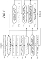
- FIG. 4 is a flowchart illustrating exemplary operation procedure of the control device 102.
- the procedure illustrated in FIG. 4 is performed, for example, every 1 minute in accordance with the unit time period of the first electric energy.
- the control device 102 receives information pertaining to an ambient temperature, that is to say, data pertaining to the ambient temperature detected by the temperature sensor 103 (Step S2).
- the temperature determinator 128 included in the control device 102 determines whether the ambient temperature detected by the temperature sensor 103 is greater than or equal to the first temperature or less than the second temperature (Step S4).
- the second temperature is less than the first temperature.
- the temperature determinator 128 determines that the ambient temperature is greater than or equal to the second temperature and less than the first temperature (No in Step S4)
- the following control, performed by the charge and discharge instructor 120, over charge and discharge of the storage battery 100 is not performed. That is to say, since the electric power consumption of the load 108 is determined to be unlikely to increase to the extent where the second electric energy exceeds the peak value in the past, the charge and discharge instructor 120 may stop operation.
- the storage battery 100 may be instructed to charge and discharge according to a conventional technique. Examples of the conventional technique include a technique of causing discharge during a predetermined time period in day time and cause charge during a predetermined time period in night time.
- the control device 102 When the temperature determinator 128 determines that the ambient temperature is greater than or equal to the first temperature and less than the second temperature (Yes in Step S4), the control device 102 operates the charge and discharge instructor 120 for the following control.
- the control device 102 receives the first electric energy (Step S6), receives the second electric energy (Step S8), and controls the calculator 126 to obtain the difference value or the differential value of the first electric energy (Step S10).
- Step S6, Step S8, and Step S10 respectively correspond to a first monitoring step, a second monitoring step, and an calculation step according to the present disclosure.
- a step described below, performed by the charge and discharge instructor 120, of instructing the storage battery 100 to charge and discharge corresponds to an instruction step according to the present disclosure.
- Step S12 When the storage battery 100 is instructed to discharge (Yes in Step S12), and, when the difference value or the differential value of the first electric energy is less than the negative predetermined value (Yes in Step S14), the charge and discharge instructor 120 stops the discharge from the storage battery 100 (Step S16).
- Step S16 After Step S16 and when the storage battery 100 is not instructed to discharge (No in Step S12) or when the difference value or the differential value of the first electric energy is not less than the negative predetermined value (No in Step S14), the charge and discharge instructor 120 determines whether the estimated value of the second electric energy is less than the second threshold value (Step S18). When determining that the estimated value of the second electric energy is less than the second threshold value (Yes in Step S18), the charge and discharge instructor 120 instructs the storage battery 100 to charge (Step S20). As described above, to prevent circumstances where electric power in the storage battery 100 is in shortage when the storage battery 100 is instructed to discharge, the charge and discharge instructor 120 proactively instructs the storage battery 100 to charge when the estimated value of the second electric energy is less than the second threshold value TH2.
- Step S20 After Step S20 or when determining that the estimated value of the second electric energy is greater than or equal to the second threshold value (No in Step S18), the charge and discharge instructor 120 determines whether the estimated value of the second electric energy is greater than or equal to the first threshold value (Step S22). When the second electric energy is greater than or equal to the first threshold value (Yes in Step S22) and when the difference value or the differential value of the first electric energy is minimum after being a positive value (Yes in Step S24), the charge and discharge instructor 120 instructs the storage battery 100 to start to discharge (Step S26).
- Step S26 After Step S26, and when determining that the estimated value of the second electric energy is less than the first threshold value (No in Step S22) or when the difference value or the differential value of the first electric energy is not minimum after being a positive value (No in Step S24), the control device 102 ends the series of processing.
- the control device 102 may instruct the storage battery 100 to discharge electric power to supply the load 108 located in the consumer site at any time when the difference value or the differential value of the first electric energy is minimum after being a positive value while taking into account the peak value in the past pertaining to the second electric energy. Accordingly, the peak electric power from the system 104 is reduced with high precision, and the storage battery is charged and discharged highly efficiently.
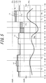
- FIG. 5 illustrates an example of charging and discharging of a storage battery for reducing the peak electric power according to the control device of the present embodiment.
- the charge and discharge instructor 120 in the example of FIG. 5 instructs the storage battery 100 to discharge before time of maximum.
- the same reference numerals are assigned to the same elements as FIG. 3 , and a description thereof is omitted.
- the charge and discharge instructor 120 receives, from the calculator 126, the difference value or the differential value of the first electric energy.
- the charge and discharge instructor 120 instructs the storage battery 100 to discharge for the load 108 in each time period when the difference value or the differential value of the first electric energy changes from a positive predetermined value to a negative predetermined value.
- the positive predetermined value differs in sign from the negative predetermined value.
- the positive predetermined value may be "+ 1 kWh"
- the negative predetermined value may be "- 1 kWh”.
- a time periods of discharge of the storage battery 100 may be adjusted.
- the charge and discharge instructor 120 starts to instruct the storage battery 100 to discharge for the load 108, and the discharge is continued until time Ty. Furthermore, at the time Tz, the charge and discharge instructor 120 starts to instruct the storage battery 100 to discharge for the load 108, and the discharge is continued until time Tw.
- discharge for the load 108 starts to be instructed at timing (i.e., time Tx and Tz) before the difference value or the differential value of the first electric energy is minimum. Accordingly, the peak electric power is reduced before the time of maxima P1 and P2.
- the maximum value in the corresponding interval is the maximum value PN1 in the example of the first embodiment (refer to FIG. 3 )
- the maximum value is reduced to a maximum value PN2 ( ⁇ the maximum value PN1) in the example of FIG. 5 .
- the charge and discharge instructor 120 when determining that the estimated value of the second electric energy PPa is less than the second threshold value TH2, the charge and discharge instructor 120 instructs the storage battery 100 to charge.
- the second threshold value TH2 is less than the first threshold value TH1
- frequent switching between charge and discharge instructions from the charge and discharge instructor 120 due to a momentary change in the second electric energy PPa is prevented.
- FIG. 6 is a flowchart illustrating exemplary operation procedure of the control device 102 according to the present embodiment.
- the same reference numerals are assigned to the same steps as FIG. 4 , and a description thereof is omitted.
- Steps S2, S4, S6, S8, and S10 in FIG. 6 are the same as those denoted by the same reference numerals in FIG. 4 , and a description thereof is omitted.
- Step S10 the control device 102 determines whether the estimated value of the second electric energy is less than the second threshold value (Step S18), instructs the storage battery 100 to charge (Step S20), and determines whether the estimated value of the second electric energy is greater than or equal to the first threshold value (Step S22).
- the charge and discharge instructor 120 instructs the storage battery 100 to start to discharge or, if the storage battery 100 is already instructed to discharge, maintains the discharge state (Step S32).
- the phrase that the difference value or the differential value of the first electric energy is within the predetermined range refers to the state where the difference value or the differential value of the first electric energy may range from the positive predetermined value to the negative predetermined value. In the example of FIG.
- Step S30 When the difference value or the differential value of the first electric energy is not within the predetermined range (No in Step S30) and when the storage battery 100 is instructed to discharge (Yes in Step S34), the charge and discharge instructor 120 stops instructing the storage battery 100 to discharge (Step S36). After Step S32, after Step S36, or when the storage battery 100 is not instructed to discharge (No in Step S34), the control device 102 ends the series of processing.
- control device 102 allows highly efficient charge and discharge of the storage battery 100 similarly to the first embodiment and may reduce the peak electric power more than the first embodiment.
- control device 102 may use a result of detection received from the voltage sensor 101 in instructing the storage battery 100 to charge and discharge. For example, when determining that the voltage of the storage battery 100 is less than a first threshold voltage, the charge and discharge instructor 120 may instruct the storage battery 100 to charge, and when determining that the voltage of the storage battery 100 is greater than or equal to a second threshold voltage, the charge and discharge instructor 120 may instruct the storage battery 100 to discharge.
- the charge and discharge instructor 120 included in the control device 102 may instruct the storage battery 100 to discharge.
Landscapes
- Engineering & Computer Science (AREA)
- Power Engineering (AREA)
- Business, Economics & Management (AREA)
- Emergency Management (AREA)
- Supply And Distribution Of Alternating Current (AREA)
- Charge And Discharge Circuits For Batteries Or The Like (AREA)
Abstract
Description
- The present application claims priority to and the benefit of
Japanese Patent Application No. 20I A--094561 (filed on April 24, 2014 - The present disclosure relates to a control method and a control device for a storage battery provided in a consumer site that receives its electric power supply from a system.
- In the context of demands for peak shift (i.e., load balancing) of electric power supply in the society as a whole and economical efficiency in consumer sites, there are proposed electric power supply systems including storage batteries interconnected to commercial electric power systems (hereinafter, simply called the systems) to store electric power supplied from the systems for later use. Such electric power supply systems may be provided in households, commercial and industrial facilities, and others to store, in the storage batteries, electric power purchased from the electric power systems during a certain time period, such as midnight, when the cost of electric power is relatively low and to supply the electric power to electric power loads located in the households or premises by discharging the storage batteries during a certain time period, such as daytime.
- For instance, Patent Literature 1 describes an electric power supply control device configured to supply electric power from a storage battery when an estimated electric energy generation is less than an estimated electric energy demand in an electric power supply system connected to a system and an electric power generator.
- PTL 1:
JP2013165534A - Herein, from the viewpoints of peak shift of electric power supply and economical efficiency, required is an electric power supply system that reduces a the peak electric power from a system thorough charge and discharge of a storage battery at appropriate timing taking the peak electric power into account. The technology described in Patent Literature 1 estimates the electric energy demand based on an electric energy demand obtained at a certain date and time in the past. For example, the time when the peak electric power is used varies with environments, such as ambient temperature conditions, and the technology described in Patent Literature 1 is not considered to reduce the peak electric power from the system with high precision, nor does it charge and discharge the storage battery highly efficiently for that purpose.
- The present disclosure has been conceived in light of the above circumstances, and the present disclosure is to provide a control method and a control device both of which allow highly efficient charge and discharge of the storage battery.
- One of aspects of the present disclosure for solving the above problem resides in a control method for a storage battery provided in a consumer site that receives electric power supply from a system, the control method including: a first monitoring step of monitoring a first electric energy supplied from the system per unit time period, where the unit time period is shorter than a predetermined time limit; a second monitoring step of monitoring a second electric energy supplied from the system per predetermined time limit; a calculation step of obtaining a change over time in the first electric energy; and an instruction step of instructing the storage battery to discharge electric power to supply a load located in the consumer site in accordance with the change over time in the first electric energy and with a peak value in the past pertaining to the second electric energy.
- Another aspect of the present disclosure for solving the above problem resides in a control device that controls a storage battery provided in a consumer site, which receives electric power supply from a system, the control device including: a calculator that obtains a change over time in a first electric energy supplied from the system per unit time period, where the unit time period is shorter than a predetermined time limit; and a charge and discharge instructor that instructs the storage battery to discharge electric power to supply a load located in the consumer site in accordance with the change over time in the first electric energy and with a peak value in the past pertaining to a second electric energy supplied from the system per predetermined time limit. (Advantageous Effect)
- A control method and a control device according to the present disclosure allow highly efficient charge and discharge of a storage battery.
- In the accompanying drawings:
-
FIG. 1 is a block diagram illustrating schematic configurations of a control device and an electric power supply system including the control device according to a first embodiment of the present disclosure; -
FIG. 2 is a schematic view illustrating changes in electric energy; -
FIG. 3 illustrates an example of charge and discharge of a storage battery for reducing a peak electric power; -
Fig. 4 is a flowchart illustrating a control method according to the first embodiment of the present disclosure; -
FIG. 5 illustrates another example of charge and discharge of a storage battery for reducing the peak electric power; and -
FIG. 6 is a flowchart illustrating a control method according to a second embodiment of the present disclosure. -
FIG. 1 is a function block diagram illustrating a schematic configuration of an electric power supply system including a control device according to a first embodiment. InFIG. 1 , electric power supplied to aload 108 is represented by a thick solid line, and solid lines with arrows indicate flow of a control signal or data. - An electric
power supply system 10 may be provided in, for example, a household or any of a variety of commercial and industrial facilities. The electricpower supply system 10 includes astorage battery 100, avoltage sensor 101 that detects voltage of thestorage battery 100, acontrol device 102 that controls charge and discharge of thestorage battery 100, and aconverter 122 that allows bidirectional conversion between an alternating current and a direct current. - Via the
converter 122, thecontrol device 102 charges thestorage battery 100 with electric power supplied from asystem 104. Thecontrol device 102 also controls thestorage battery 100 to discharge electric power to supply theload 108 located in a consumer site. That is to say, the electricpower supply system 10 may supply, to theload 108, electric power supplied from thesystem 104 and electric power charged in and then discharged from thestorage battery 100. With the electric power discharged from thestorage battery 100, the electricpower supply system 10 may reduce a peak electric power from thesystem 104. - The
control device 102 also controls conversion, performed in theconverter 122, between an alternating current supplied from thesystem 104 and a direct current in thestorage battery 100. Theconverter 122 is, for example, a bidirectional inverter. A detailed description is given later below of control, performed by thecontrol device 102, over charge and discharge of thestorage battery 100. - An
electric energy meter 25 detects an electric energy supplied (electric power purchased) from thesystem 104 and outputs pulses in accordance with the supplied electric energy. As an example, theelectric energy meter 25 outputs pulses at a rate of 2000 pulses / 1 kWh. In other words, in this example, theelectric energy meter 25 outputs 1 pulse everytime a supplied electric energy of 0.5 Wh is detected. - A
demand monitoring device 24 is a device provided for determining an electric power rate (price) at the time of receiving electric power supply. In Japan, an electric power seller supplies the electric power that a high-voltage electric power receiver, such as a commercial facility, receives from thesystem 104, and the electric power is sold and purchased according to a contract made with the electric power seller. Especially, as described below, an electric power rate used for purchase is determined by the highest value in the past 1 year among average electric energy values each calculated based on an electric energy supplied in a predetermined time limit (e.g., 30 minutes) (this electric energy corresponding to a second electric energy). - The
demand monitoring device 24 measures the second electric energy by counting the number of pulses from theelectric energy meter 25 during each predetermined time limit. The predetermined time limit refers to a predetermined time period, such as 30 minutes, and may also be called the demand time limit. The demand time limit differs depending on countries, and the demand time limit is defined, for example, as 30 minutes in Japan, 60 minutes in the U.S., and 15 minutes in Germany. The second electric energy is measured based on the number of pulses detected from the beginning to the end of the predetermined time limit. In detail, thedemand monitoring device 24 resets a count value of the number of pulses at the beginning of each predetermined time limit, counts the number of pulses from the beginning to the end of the predetermined time limit, and replaces the previous count value with the counted number as the electric energy. Thus, thedemand monitoring device 24 measures the second electric energy. - Then, the
demand monitoring device 24 converts the measured second electric energy into an average electric power value in the predetermined time limit. For example, suppose that the predetermined time limit is defined as 30 minutes and that the measured second electric energy, that is to say, an electric energy supplied in 30 minutes, is a [kWh]. In this case, the average electric power value P [kW] in 30 minutes (0.5 hour) is represented by P = a / 0.5 = 2a [kW]. Eventually, the electric power seller stores, for the past 1 year, information pertaining to average electric power values per 30 minutes and determines the electric power rate based on the highest value among the average electric power values in the past 1 year. - As described earlier, the
storage battery 100 is provided for reducing the peak electric power from thesystem 104. Thestorage battery 100 may be, for example, a lithium ion battery or a nickel metal hydride battery including a plurality of cells connected in series. Thevoltage sensor 101, which detects voltage of thestorage battery 100, transmits a result of the detection to thecontrol device 102. - The
control device 102 includes a charge anddischarge instructor 120, acalculator 126, and atemperature determinator 128 that receives an ambient temperature detected by atemperature sensor 103, and astorage 134. - The
calculator 126 operates in synchronization with thedemand monitoring device 24 and calculates the second electric energy based on pulses from the sameelectric energy meter 25 by using the same logic as thedemand monitoring device 24. That is to say, thecalculator 126 also counts, for each predetermined time limit, pulses outputted from theelectric energy meter 25 in synchronization with thedemand monitoring device 24 and calculates the second electric energy based on the number of pulses from the beginning to the end of the predetermined time limit. Thus, it is to be noted that, since thecalculator 126 is temporally synchronized and obtains the electric energy from the same source, the same value of the second electric energy is measured by thecalculator 126. That is to say, the second electric energy monitored by thedemand monitoring device 24 may be monitored by the control device 102 (the calculator 126). - Furthermore, the
calculator 126 counts, for each time period (e.g., 1 minute, which may also be called the unit time period below) that is shorter than the predetermined time limit, the number of pulses and calculates an electric energy supplied in the unit time period (this electric energy corresponding to a first electric energy). Thecalculator 126 then calculates, as a change over time in the first electric energy, a difference in the first electric energy supplied in consecutive unit time periods or calculates a value obtained by differentiating the first electric energy by the time period. In detail, thecalculator 126 calculates, as a difference value of the first electric energy, a difference Δ = W(k) - W(k-1) between the first electric energy W(k-1) at time k-1 and the first electric energy W(k) at time k that are each discretized by the unit time period. Alternatively, thecalculator 126 calculates an approximate curve based on a plot of a plurality of values of the first electric energy with use of, for example, the least-square approach and calculates, as a differential value of the first electric energy, an inclination of the approximate curve at arbitrary time. - The
calculator 126 also calculates, for each unit time period, an estimated value of the second electric energy. Herein, the estimated value of the second electric energy is a value obtained, for example, by multiplying the predetermined time limit (e.g., 30 minutes), and a value obtained by dividing a sum of the first electric energy (W(1) + W(2) + ... + W(n)) supplied from the beginning (time k = 0) to a current time (time k = n) of a predetermined time limit to which the current time belongs by a time period (e.g., n minutes) from the beginning of the predetermined time limit to the current time. That is to say, the estimated value of the second electric energy refers to a value of the second electric energy expected at the end of the predetermined time limit that is yet to come. - Moreover, the
calculator 126 transmits, to thestorage 134, the first electric energy, the change over time in the first electric energy, the second electric energy, a peak value in the past pertaining to the second electric energy, the estimated value of the second electric energy, or the like calculated by thecalculator 126, and subsequently stores the transmitted data together with other data, such as a first threshold value and a second threshold value that are described later. - The charge and
discharge instructor 120 instructs thestorage battery 100 to discharge electric power to supply theload 108 located in the consumer site in accordance with the change over time in the first electric energy and the peak value (maximum value) in the past pertaining to the second electric energy. The charge anddischarge instructor 120 receives, from thecalculator 126, the second electric energy calculated by the current time and monitors the second electric energy (i.e., an integrated electric energy monitored by the demand monitoring device 24). - Based on the change over time in the first electric energy in the predetermined time limit to which the current time belongs, the charge and
discharge instructor 120 detects, for example, that the difference value or the differential value of the first electric energy is minimum after being a positive value, and by doing so, the charge anddischarge instructor 120 grasps that the peak electric power (i.e., an electric power that might exceed the peak value in the past) is likely to be used in that predetermined time limit. As described later, the charge anddischarge instructor 120 may detect that the difference value or the differential value of the first electric energy is minimum after being a positive value while taking into consideration the peak value in the past pertaining to the second electric energy and may instruct thestorage battery 100 to discharge electric power to supply theload 108 located in the consumer site. Accordingly, the peak electric power from thesystem 104 is reduced with high precision, and thestorage battery 100 is charged and discharged highly efficiently. - Additionally, the term minimum herein refers to a changing point from a positive value to zero or a negative value. The minimum is not necessarily zero. Especially, since the
calculator 126 measures the first electric energy once every unit time period, zero is detected as the difference value of first electric energy only when the first electric energy remains completely the same two consecutive times, and such a case is very rare. Accordingly, cases where the difference value of first electric energy changes from, for example, "+ 4 kWh" to "+ 1 kWh" and to "- 3 kWh", without zero being detected, are considered to occur frequently. In such a case, the charge anddischarge instructor 120 determines the negative value "- 3 kWh" as minimum. Alternatively, the charge anddischarge instructor 120 may also determine that the difference value or the differential value of the first electric energy is minimum when the difference value or the differential value changes to be less than or equal to a predetermined reference value (e.g., "+ 2 kWh"), which is a positive value close to zero. For example, the charge anddischarge instructor 120 determines that the difference value or the differential value of the first electric energy is minimum when the difference value or the differential value changes from a value greater than the reference value to be within the range from zero to the reference value. Preferably, the charge anddischarge instructor 120 determines that the difference value or the differential value of the first electric energy is minimum when the difference value or the differential value stays within the aforementioned range several consecutive times or for a predetermined time period after falling, from a value greater than the reference value, within the range. - The charge and
discharge instructor 120 may also instruct thestorage battery 100 to start to discharge for theload 108 when the difference value or the differential value of the first electric energy is minimum after being a positive value. At this time, thecontrol device 102 may reduce electric power to be purchased from thesystem 104 at appropriate timing. This allows thecontrol device 102 to prevent use of an electric energy exceeding the peak value in the past pertaining to the second electric energy as much as possible. Furthermore, even when the peak value is to be updated in the event of use of an electric energy exceeding the peak value in the past, thecontrol device 102 may reduce the increase. - Preferably, when the difference value or the differential value of the first electric energy is minimum after being a positive value, the charge and
discharge instructor 120 compares the estimated value of the second electric energy with the first threshold value. When the estimated value of the second electric energy is greater than the first threshold value, the charge anddischarge instructor 120 may instruct thestorage battery 100 to start to discharge for theload 108. By setting the first threshold, thecontrol device 102 may reduce unnecessary discharge and perform charge and discharge of thestorage battery 100 even more efficiently. At this time, if the estimated value of the second electric energy is less than the first threshold value, the charge anddischarge instructor 120 does not instruct thestorage battery 100 to discharge. For example, as described later, in cases where the first threshold value is determined based on the peak value in the past pertaining to the second electric energy, the charge anddischarge instructor 120 may instruct thestorage battery 100 to discharge only when the second electric energy is likely to exceed the peak value (i.e., only when a contract demand is likely to be updated). This prevents circumstances where electric power in thestorage battery 100 is in shortage before thestorage battery 100 is instructed to discharge. - The charge and
discharge instructor 120 also acquires, from thestorage 134, the peak value in the past pertaining to the second electric energy. Herein, when the peak value in the past pertaining to the second electric energy is updated, the charge anddischarge instructor 120 may store, in thestorage 134, the peak value in the past as a result of the update. - The first threshold value may be determined in accordance with the peak value in the past pertaining to the second electric energy. Although the first threshold value may be the peak value in the past itself, the first threshold value is preferably slightly less than the peak value in the past with a slight margin from the peak value. For example, the
control device 102 may determine the first threshold by subtracting a predetermined value from the peak value in the past and store the determined value in thestorage 134. When the peak value in the past is updated, a new first threshold value is determined in conjunction with the peak value as a result of the update. The above configuration allows thecontrol device 102 to control discharge of thestorage battery 100 flexibly in accordance with current conditions. - Based on the peak value in the past pertaining to the second electric energy that is acquired from the
storage 134, the charge anddischarge instructor 120 may also instruct thestorage battery 100 to discharge for theload 108 so that the final second electric energy in the predetermined time limit to which the current time belongs will not exceed the peak value in the past. At this time, thecontrol device 102 may regulate the electric power that is to be discharged from thestorage battery 100 in correspondence to the peak value in the past pertaining to the second electric energy, and accordingly, perform control to further prevent update of the contract demand. - The charge and
discharge instructor 120 also compares the estimated value of the second electric energy with the second threshold value. The charge anddischarge instructor 120 may also instruct thestorage battery 100 to charge when determining that the estimated value of the second electric energy is less than the second threshold value. By setting the second threshold value, thecontrol device 102 may control the timing of charge to thestorage battery 100. Herein, the second threshold value is less than or equal to the first threshold value. When the second threshold value is equal to the first threshold value, thestorage battery 100 is charged proactively unless thestorage battery 100 is instructed to discharge. The second threshold value may similarly be determined based on the peak value in the past pertaining to the second electric energy. For example, thecontrol device 102 may determine the first threshold by subtracting a predetermined value from the peak value in the past pertaining to the second electric energy and store the determined value in thestorage 134. - Herein, the charge and
discharge instructor 120 may perform the aforementioned control when thetemperature determinator 128 determines that an ambient temperature is greater than or equal to a first temperature or less than a second temperature that is less than the first temperature. When the ambient temperature is greater than or equal to the first temperature (e.g., 25 °C), an electric power consumption of theload 108 may be increased due to the high temperature. When the ambient temperature is less than the second temperature (e.g., 10 °C), the electric power consumption of theload 108 may be increased due to the low temperature. The aforementioned control may be performed effectively when the electric power consumption of theload 108 may be increased. - Next, a description is given in detail of control, performed by the
control device 102, over charge and discharge of thestorage battery 100.FIG. 2 is a schematic view illustrating electric power supplied from thesystem 104. InFIG. 2 , a plurality of values of the second electric energy on a certain day is represented by a bar graph. The example ofFIG. 2 illustrates the second electric energy PPa while thestorage battery 100 is not instructed to charge nor to discharge by thecontrol device 102 as described above. - In
FIG. 2 , the peak value (hereinafter, called the peak value P0a) in the past pertaining to the second electric energy is 40 kWh according to the contract demand. The first threshold value TH1 and the second threshold value TH2 are set to 35 kWh. In an interval Rx from 10 : 30 to 17 : 00, the second electric energy PPa reaches three maxima, and the second electric energy PPa at maxima P1 and P2 are greater than or equal to the first threshold value TH1, and the second electric energy PPa at maximum Px is less than the first threshold value TH1. -
FIG. 3 illustrates an example of charge and discharge of thestorage battery 100 for reducing the peak electric power.FIG. 3 enlarges a portion ofFIG. 2 that corresponds to the interval Rx. In the example ofFIG. 3 , thetemperature determinator 128 determines that the ambient temperature detected by thetemperature sensor 103 is greater than or equal to the first temperature, and the charge anddischarge instructor 120 instructs thestorage battery 100 to charge and discharge. Accordingly, unlikeFIG. 2 ,FIG. 3 illustrates a discharged electric energy PDa and a charged electric energy PCa. That is to say, the second electric energy PPa illustrated inFIG. 3 is reduced by the discharged electric energy PDa discharged from thestorage battery 100 and increased by the charged electric energy PCa charged to thestorage battery 100. - Firstly, a description is given of discharge in the example of
FIG. 3 .As described earlier, the charge anddischarge instructor 120 detects that the difference value or the differential value of the first electric energy PMa is minimum after being a positive value. Herein, for improved visualization,FIG. 3 (andFIG. 5 ) illustrate the first electric energy PMa by a curve, not by a bar graph. - In the example of
FIG. 3 , the charge anddischarge instructor 120 instructs thestorage battery 100 to discharge for theload 108 at time Ta and time Tc, that is to say, at each time when the difference value or the differential value of the first electric energy PMa is minimum after being a positive value. Consequently, at each of the maxima P1 and P2 illustrated inFIG. 3 , the second electric energy PPa is reduced by the corresponding discharged electric energy PDa. Additionally, the charge anddischarge instructor 120 also regulates the discharged electric energy PDa so that the second electric energy in any time limit (from 11 : 30 to 12 : 00 and from 16 : 00 to 16 : 30 in this example) in which the charge anddischarge instructor 120 instructs thestorage battery 100 to start discharge will not exceed the peak value P0a. - In the example illustrated in
FIG. 3 , not only the time of maximum but also the estimated value of the second electric energy PPa being greater than or equal to the first threshold value TH1 is regarded as conditions of discharge by the charge anddischarge instructor 120. Accordingly, the charge anddischarge instructor 120 does not cause discharge at the time of maximum Px. That is to say, in cases where the second electric energy is not likely to exceed the peak value in the past (i.e., the contract demand is not likely to be updated), thecontrol device 102 does not cause discharge even when the difference value or the differential value of the first electric energy is minimum after being a positive value. By setting the estimated value of the second electric energy PPa being greater than or equal to the first threshold TH1 as the conditions of discharge, unwanted discharge is prevented. - At the time Ta, the charge and
discharge instructor 120 starts to instruct thestorage battery 100 to discharge for theload 108, and the discharge is continued until the time Tb, when the difference value or the differential value of the first electric energy is a negative predetermined value. Furthermore, at the time Tc, the charge anddischarge instructor 120 starts to instruct thestorage battery 100 to discharge for theload 108, and the discharge is continued until time Td, when the difference value or the differential value of the first electric energy is a negative predetermined value. In the example ofFIG. 3 , the negative predetermined value is a difference in the first electric energy and may be a value, such as "- 1 kWh". Herein, selecting a value with a large absolute value as the negative predetermined value prolongs a time period of discharge for theload 108. For instance, by changing the negative predetermined value from "- 1 kWh" to "- 1.5 kWh", the time period of discharge is prolonged. Thus, the time period of discharge for theload 108 may be regulated depending on the predetermined value selected. - Herein, in another embodiment, the charge and
discharge instructor 120 may stop discharge for theload 108 at border time between two consecutive predetermined time limits (i.e., at the beginning of a next predetermined time limit). This other embodiment is described with reference to the example ofFIG. 3 . At the time Ta, the charge anddischarge instructor 120 starts to instruct thestorage battery 100 to discharge for theload 108, and at time Te, which is border time between predetermined time periods, the discharge is stopped. At this time, upon starting to monitor a new predetermined time limit, thecontrol device 102 stops charge to or discharge from thestorage battery 100, and this allows thecontrol device 102 to manage charge and discharge in the unit of a predetermined time limit. In this other embodiment, control over charge and discharge is simplified, and load on thecontrol device 102 for arithmetic processing is reduced. - Secondly, with reference to
FIG. 3 , a description is given of control over charge according to the present embodiment. When determining that the estimated value of the second electric energy PPa is less than the second threshold value TH2, the charge anddischarge instructor 120 instructs thestorage battery 100 to charge. In the example ofFIG. 3 , the charge anddischarge instructor 120 instructs thestorage battery 100 to charge in time periods from 10 : 30 to 11 : 00, from 12 : 30 to 13 : 30, from 14 : 00 to 15 : 30, and from 16 : 30 to 17 : 00. By instructing thestorage battery 100 to charge proactively when the estimated value of the second electric energy PPa is less than the second threshold value TH2, the charge anddischarge instructor 120 prevents circumstances where electric power in thestorage battery 100 is in shortage when thestorage battery 100 is instructed to discharge. - By the charge and
discharge instructor 120 instructing thestorage battery 100 to discharge in this way, the peak electric power is reduced at the time (of the maxima P1 and P2 in the example ofFIG. 3 ) when the difference value or the differential value of the first electric energy is minimum after being a positive value. Providing that the charge anddischarge instructor 120 does not instruct thestorage battery 100 to discharge, at the maximum P2, the second electric energy PPa would be a maximum value PN0. However, by the charge anddischarge instructor 120 instructing thestorage battery 100 to discharge, the second electric energy PPa stays within a maximum value PN1 at most. Herein, the maximum value PN1 is less than the maximum value PN0. As described earlier, the contract demand is determined by the highest value among values of electric power averaged per predetermined time limit in the past 1 year. Accordingly, by the charge anddischarge instructor 120 thus reducing the peak electric power, the demands for economical efficiency in the consumer site are met. -
FIG. 4 is a flowchart illustrating exemplary operation procedure of thecontrol device 102. The procedure illustrated inFIG. 4 is performed, for example, every 1 minute in accordance with the unit time period of the first electric energy. - To start with, the
control device 102 receives information pertaining to an ambient temperature, that is to say, data pertaining to the ambient temperature detected by the temperature sensor 103 (Step S2). Thetemperature determinator 128 included in thecontrol device 102 determines whether the ambient temperature detected by thetemperature sensor 103 is greater than or equal to the first temperature or less than the second temperature (Step S4). Herein, the second temperature is less than the first temperature. - When the
temperature determinator 128 determines that the ambient temperature is greater than or equal to the second temperature and less than the first temperature (No in Step S4), the following control, performed by the charge anddischarge instructor 120, over charge and discharge of thestorage battery 100 is not performed. That is to say, since the electric power consumption of theload 108 is determined to be unlikely to increase to the extent where the second electric energy exceeds the peak value in the past, the charge anddischarge instructor 120 may stop operation. At this time, thestorage battery 100 may be instructed to charge and discharge according to a conventional technique. Examples of the conventional technique include a technique of causing discharge during a predetermined time period in day time and cause charge during a predetermined time period in night time. - When the
temperature determinator 128 determines that the ambient temperature is greater than or equal to the first temperature and less than the second temperature (Yes in Step S4), thecontrol device 102 operates the charge anddischarge instructor 120 for the following control. - The
control device 102 receives the first electric energy (Step S6), receives the second electric energy (Step S8), and controls thecalculator 126 to obtain the difference value or the differential value of the first electric energy (Step S10). Step S6, Step S8, and Step S10 respectively correspond to a first monitoring step, a second monitoring step, and an calculation step according to the present disclosure. Furthermore, a step described below, performed by the charge anddischarge instructor 120, of instructing thestorage battery 100 to charge and discharge corresponds to an instruction step according to the present disclosure. - When the
storage battery 100 is instructed to discharge (Yes in Step S12), and, when the difference value or the differential value of the first electric energy is less than the negative predetermined value (Yes in Step S14), the charge anddischarge instructor 120 stops the discharge from the storage battery 100 (Step S16). - After Step S16 and when the
storage battery 100 is not instructed to discharge (No in Step S12) or when the difference value or the differential value of the first electric energy is not less than the negative predetermined value (No in Step S14), the charge anddischarge instructor 120 determines whether the estimated value of the second electric energy is less than the second threshold value (Step S18). When determining that the estimated value of the second electric energy is less than the second threshold value (Yes in Step S18), the charge anddischarge instructor 120 instructs thestorage battery 100 to charge (Step S20). As described above, to prevent circumstances where electric power in thestorage battery 100 is in shortage when thestorage battery 100 is instructed to discharge, the charge anddischarge instructor 120 proactively instructs thestorage battery 100 to charge when the estimated value of the second electric energy is less than the second threshold value TH2. - After Step S20 or when determining that the estimated value of the second electric energy is greater than or equal to the second threshold value (No in Step S18), the charge and
discharge instructor 120 determines whether the estimated value of the second electric energy is greater than or equal to the first threshold value (Step S22). When the second electric energy is greater than or equal to the first threshold value (Yes in Step S22) and when the difference value or the differential value of the first electric energy is minimum after being a positive value (Yes in Step S24), the charge anddischarge instructor 120 instructs thestorage battery 100 to start to discharge (Step S26). - After Step S26, and when determining that the estimated value of the second electric energy is less than the first threshold value (No in Step S22) or when the difference value or the differential value of the first electric energy is not minimum after being a positive value (No in Step S24), the
control device 102 ends the series of processing. - The
control device 102 according to the present embodiment that is configured as above may instruct thestorage battery 100 to discharge electric power to supply theload 108 located in the consumer site at any time when the difference value or the differential value of the first electric energy is minimum after being a positive value while taking into account the peak value in the past pertaining to the second electric energy. Accordingly, the peak electric power from thesystem 104 is reduced with high precision, and the storage battery is charged and discharged highly efficiently. - A control device according to a second embodiment of the present disclosure will be described below. The configuration of the control device according to the present embodiment is the same as the control device according to the first embodiment (refer to
FIG. 1 ), and a description thereof is omitted.FIG. 5 illustrates an example of charging and discharging of a storage battery for reducing the peak electric power according to the control device of the present embodiment. Unlike the example of the first embodiment (refer toFIG. 3 ), the charge anddischarge instructor 120 in the example ofFIG. 5 instructs thestorage battery 100 to discharge before time of maximum. Furthermore, inFIG. 5 , the same reference numerals are assigned to the same elements asFIG. 3 , and a description thereof is omitted. - Firstly, a description is given of discharge in the example of
FIG. 5 . Similarly to the first embodiment, the charge anddischarge instructor 120 receives, from thecalculator 126, the difference value or the differential value of the first electric energy. The charge anddischarge instructor 120 instructs thestorage battery 100 to discharge for theload 108 in each time period when the difference value or the differential value of the first electric energy changes from a positive predetermined value to a negative predetermined value. Herein, the positive predetermined value differs in sign from the negative predetermined value. For example, the positive predetermined value may be "+ 1 kWh", and the negative predetermined value may be "- 1 kWh". Similarly to the first embodiment, by setting these predetermined values, a time periods of discharge of thestorage battery 100 may be adjusted. - In the example of
FIG. 5 , at time Tx, the charge anddischarge instructor 120 starts to instruct thestorage battery 100 to discharge for theload 108, and the discharge is continued until time Ty. Furthermore, at the time Tz, the charge anddischarge instructor 120 starts to instruct thestorage battery 100 to discharge for theload 108, and the discharge is continued until time Tw. In the example ofFIG. 5 , unlike the first embodiment, discharge for theload 108 starts to be instructed at timing (i.e., time Tx and Tz) before the difference value or the differential value of the first electric energy is minimum. Accordingly, the peak electric power is reduced before the time of maxima P1 and P2. Although the maximum value in the corresponding interval is the maximum value PN1 in the example of the first embodiment (refer toFIG. 3 ), the maximum value is reduced to a maximum value PN2 (< the maximum value PN1) in the example ofFIG. 5 . - Next, a description is given of charge in the example of
FIG. 5 . Similarly to the first embodiment, when determining that the estimated value of the second electric energy PPa is less than the second threshold value TH2, the charge anddischarge instructor 120 instructs thestorage battery 100 to charge. Herein, since in the example ofFIG. 5 the second threshold value TH2 is less than the first threshold value TH1, frequent switching between charge and discharge instructions from the charge anddischarge instructor 120 due to a momentary change in the second electric energy PPa is prevented. -
FIG. 6 is a flowchart illustrating exemplary operation procedure of thecontrol device 102 according to the present embodiment. InFIG. 6 , the same reference numerals are assigned to the same steps asFIG. 4 , and a description thereof is omitted. For example, Steps S2, S4, S6, S8, and S10 inFIG. 6 are the same as those denoted by the same reference numerals inFIG. 4 , and a description thereof is omitted. - After Step S10, the
control device 102 determines whether the estimated value of the second electric energy is less than the second threshold value (Step S18), instructs thestorage battery 100 to charge (Step S20), and determines whether the estimated value of the second electric energy is greater than or equal to the first threshold value (Step S22). These steps are the same as those denoted by the same reference numerals inFIG. 4 , and a description is omitted. - When the estimated value of the second electric energy is greater than or equal to the first threshold value (Yes in Step S22) and when the difference value or the differential value of the first electric energy is within a predetermined range (Yes in Step S30), the charge and
discharge instructor 120 instructs thestorage battery 100 to start to discharge or, if thestorage battery 100 is already instructed to discharge, maintains the discharge state (Step S32). Herein, the phrase that the difference value or the differential value of the first electric energy is within the predetermined range refers to the state where the difference value or the differential value of the first electric energy may range from the positive predetermined value to the negative predetermined value. In the example ofFIG. 5 , when the difference value or the differential value of the first electric energy is in the range from "+ 1 kWh", which is the positive predetermined value, to "- 1 kWh", which is the negative predetermined value, the charge anddischarge instructor 120 instructs thestorage battery 100 to discharge. - When the difference value or the differential value of the first electric energy is not within the predetermined range (No in Step S30) and when the
storage battery 100 is instructed to discharge (Yes in Step S34), the charge anddischarge instructor 120 stops instructing thestorage battery 100 to discharge (Step S36). After Step S32, after Step S36, or when thestorage battery 100 is not instructed to discharge (No in Step S34), thecontrol device 102 ends the series of processing. - Thus, the
control device 102 according to the second embodiment allows highly efficient charge and discharge of thestorage battery 100 similarly to the first embodiment and may reduce the peak electric power more than the first embodiment. - Although the present disclosure has been described based on the drawings and the embodiments, it is to be noted that a person skilled in the art may easily make various changes and modifications according to the present disclosure. Therefore, note that such changes and modifications are included within the scope of the present disclosure. For example, functions and so forth included in various blocks, steps, or the like may be rearranged in any logically consistent way. Furthermore, blocks and steps may be combined into one or may be divided.
- As an example, the
control device 102 may use a result of detection received from thevoltage sensor 101 in instructing thestorage battery 100 to charge and discharge. For example, when determining that the voltage of thestorage battery 100 is less than a first threshold voltage, the charge anddischarge instructor 120 may instruct thestorage battery 100 to charge, and when determining that the voltage of thestorage battery 100 is greater than or equal to a second threshold voltage, the charge anddischarge instructor 120 may instruct thestorage battery 100 to discharge. - Furthermore, when, for example, the difference value or the differential value of the first electric energy is large and when the second electric energy is expected to exceed the peak value in the past according to the contract demand, the charge and
discharge instructor 120 included in thecontrol device 102 may instruct thestorage battery 100 to discharge. -
- 10
- Electric power supply system
- 24
- Demand monitoring device
- 25
- Electric energy meter
- 100
- Storage battery
- 101
- Voltage sensor
- 102
- Control device
- 103
- Temperature sensor
- 104
- System
- 108
- Load
- 120
- Charge and discharge instructor
- 122
- Converter
- 126
- Calculator
- 128
- Temperature determinator
- 134
- Storage
Claims (10)
- A control method for a storage battery provided in a consumer site that receives electric power supply from a system, the control method comprising:a first monitoring step of monitoring a first electric energy supplied from the system per unit time period, where the unit time period is shorter than a predetermined time limit;a second monitoring step of monitoring a second electric energy supplied from the system per predetermined time limit;a calculation step of obtaining a change over time in the first electric energy; andan instruction step of instructing the storage battery to discharge electric power to supply a load located in the consumer site in accordance with the change over time in the first electric energy and with a peak value in the past pertaining to the second electric energy.
- The control method of claim 1, wherein
in the instruction step,
in accordance with the change over time in the first electric energy, when a difference value or a differential value of the first electric energy is zero or a negative value after being a positive value or when the differential value or the derivative value of the first electric energy is within the range of from zero to a predetermined reference value after being a value greater than the predetermined reference value, the storage battery is instructed to start to discharge. - The control method of claim 2, wherein
in the instruction step,
when an estimated value of the second electric energy is greater than a first threshold value, the storage battery is instructed to start to discharge, and when the estimated value is less than the first threshold value, the storage battery is not instructed to discharge, the estimated value of the second electric energy being calculated based on the first electric energy from beginning of a predetermined time limit to which a current time belongs to the current time. - The control method of claim 3, wherein the first threshold value varies according to the peak value.
- The control method of any one of claims 2 to 4, wherein
in the instruction step,
when the storage battery is instructed to start to discharge, the storage battery is instructed to start to discharge so that the second electric energy in a predetermined time limit to which a current time belongs does not exceed the peak value. - The control method of any one of claims 1 to 5, wherein
in the instruction step,
when an estimated value of the second electric energy is less than a second threshold value, the storage battery is instructed to charge, the estimated value of the second electric energy being calculated based on the first electric energy from beginning of a predetermined time limit to which a current time belongs to the current time. - The control method of any one of claims 1 to 6, wherein
in the instruction step,
when monitoring of a new predetermined time limit is started in the second monitoring step while the storage battery is being charged or discharged, the charge or the discharge of the storage battery is stopped. - The control method of any one of claims 1 to 7, wherein
the instruction step is performed when an ambient temperature of the consumer site is determined to be greater than or equal to a first temperature or to be less than a second temperature that is lower than the first temperature. - The control method of claim 1, wherein
in the instruction step,
in accordance with the change over time in the first electric energy, the storage battery is instructed to discharge during a time period in which a difference value or a differential value of the first electric energy changes from a positive predetermined value to a negative predetermined value. - A control device that controls a storage battery provided in a consumer site, which receives electric power supply from a system, the control device comprising:a calculator that obtains a change over time in a first electric energy supplied from the system per unit time period, where the unit time period is shorter than a predetermined time limit; anda charge and discharge instructor that instructs the storage battery to discharge electric power to supply a load located in the consumer site in accordance with the change over time in the first electric energy and with a peak value in the past pertaining to a second electric energy supplied from the system per predetermined time limit.
Applications Claiming Priority (2)
| Application Number | Priority Date | Filing Date | Title |
|---|---|---|---|
| JP2014090561 | 2014-04-24 | ||
| PCT/JP2015/002252 WO2015162941A1 (en) | 2014-04-24 | 2015-04-24 | Control method and control device |
Publications (3)
| Publication Number | Publication Date |
|---|---|
| EP3136533A1 true EP3136533A1 (en) | 2017-03-01 |
| EP3136533A4 EP3136533A4 (en) | 2017-12-20 |
| EP3136533B1 EP3136533B1 (en) | 2019-11-13 |
Family
ID=54332115
Family Applications (1)
| Application Number | Title | Priority Date | Filing Date |
|---|---|---|---|
| EP15783548.9A Active EP3136533B1 (en) | 2014-04-24 | 2015-04-24 | Control method and control device |
Country Status (4)
| Country | Link |
|---|---|
| US (1) | US10348087B2 (en) |
| EP (1) | EP3136533B1 (en) |
| JP (1) | JP6317431B2 (en) |
| WO (1) | WO2015162941A1 (en) |
Cited By (1)
| Publication number | Priority date | Publication date | Assignee | Title |
|---|---|---|---|---|
| CN112787356A (en) * | 2019-11-11 | 2021-05-11 | 阿里巴巴集团控股有限公司 | Discharge device, system, method and storage medium |
Families Citing this family (2)
| Publication number | Priority date | Publication date | Assignee | Title |
|---|---|---|---|---|
| CN113747548B (en) * | 2020-05-27 | 2023-11-10 | 上海华为技术有限公司 | Electric energy control methods and related equipment |
| WO2024070016A1 (en) * | 2022-09-29 | 2024-04-04 | 株式会社日立ハイテク | Charging plan creation method, charging plan creation device, and charging plan providing system |
Family Cites Families (15)
| Publication number | Priority date | Publication date | Assignee | Title |
|---|---|---|---|---|
| US6870279B2 (en) * | 1998-01-05 | 2005-03-22 | Capstone Turbine Corporation | Method and system for control of turbogenerator power and temperature |
| JP3737640B2 (en) * | 1998-11-06 | 2006-01-18 | 株式会社東芝 | Power fluctuation detection device and computer-readable storage medium |
| JP2006158146A (en) * | 2004-12-01 | 2006-06-15 | Toko Electric Corp | Power supply management system |
| JP5288782B2 (en) | 2007-03-09 | 2013-09-11 | 三洋電機株式会社 | Demand control system, demand controller, demand program, and demand control method |
| CN101877487B (en) * | 2009-04-30 | 2013-04-10 | 比亚迪股份有限公司 | Battery energy storage power station and method for balancing power network load |
| US8478452B2 (en) * | 2010-04-06 | 2013-07-02 | Battelle Memorial Institute | Grid regulation services for energy storage devices based on grid frequency |
| JP2013165534A (en) | 2010-06-03 | 2013-08-22 | Sanyo Electric Co Ltd | Power supply control device |
| WO2012127595A1 (en) * | 2011-03-18 | 2012-09-27 | 富士通株式会社 | Power-leveling control apparatus, power leveling power-storage apparatus, power-leveling control method, and leveling program |
| WO2013038483A1 (en) * | 2011-09-13 | 2013-03-21 | 東芝三菱電機産業システム株式会社 | Peak cut system |
| US8774976B2 (en) * | 2012-05-31 | 2014-07-08 | Sharp Laboratories Of America, Inc. | Method and system for reducing peak load charge on utility bill using target peak load and countermeasures |
| CN105359369A (en) * | 2013-03-19 | 2016-02-24 | 法国电力公司 | Energy management device and its associated method |
| GB2514092B (en) * | 2013-03-21 | 2017-11-29 | Powervault Ltd | Electrical energy storage device and system |
| US9660450B2 (en) * | 2013-10-17 | 2017-05-23 | Zhangjiakou Wind And Solar Power Energy Demonstration | Monitoring system and method for megawatt level battery energy storage power plant |
| US10747289B2 (en) * | 2013-10-28 | 2020-08-18 | Virtual Power Systems, Inc. | Data center power manipulation |
| US9956027B2 (en) * | 2014-06-11 | 2018-05-01 | Encision Inc. | Device and method for detecting faults in a shielded instrument |
-
2015
- 2015-04-24 US US15/306,476 patent/US10348087B2/en active Active
- 2015-04-24 EP EP15783548.9A patent/EP3136533B1/en active Active
- 2015-04-24 JP JP2016514730A patent/JP6317431B2/en active Active
- 2015-04-24 WO PCT/JP2015/002252 patent/WO2015162941A1/en not_active Ceased
Cited By (1)
| Publication number | Priority date | Publication date | Assignee | Title |
|---|---|---|---|---|
| CN112787356A (en) * | 2019-11-11 | 2021-05-11 | 阿里巴巴集团控股有限公司 | Discharge device, system, method and storage medium |
Also Published As
| Publication number | Publication date |
|---|---|
| JPWO2015162941A1 (en) | 2017-04-13 |
| JP6317431B2 (en) | 2018-04-25 |
| EP3136533B1 (en) | 2019-11-13 |
| US10348087B2 (en) | 2019-07-09 |
| EP3136533A4 (en) | 2017-12-20 |
| WO2015162941A1 (en) | 2015-10-29 |
| US20170047736A1 (en) | 2017-02-16 |
Similar Documents
| Publication | Publication Date | Title |
|---|---|---|
| EP2475060B1 (en) | Energy storage system | |
| CN104303386B (en) | Power control unit and electrical control method | |
| EP2602902B1 (en) | Power supplying system | |
| EP2744063B1 (en) | Energy management device, energy management system, and program | |
| EP3018486A1 (en) | Vehicle storage battery management device, vehicle power unit, and vehicle storage battery management method | |
| EP3073597A1 (en) | Storage battery control device, control method, control program, and electricity storage system | |
| WO2016084396A1 (en) | Power control device, power control method, and power control system | |
| US10496060B2 (en) | Power management system and method for power management | |
| EP3136533B1 (en) | Control method and control device | |
| WO2015056634A1 (en) | Electricity storage system | |
| JP2014217195A (en) | Charge setting device, power adjustment device | |
| EP2830183B1 (en) | Power consumption mode guiding device and system | |
| JP6181201B2 (en) | Storage battery control device | |
| JP2013201819A (en) | Storage battery control device | |
| JP6415872B2 (en) | Electric power demand control device | |
| JP5964668B2 (en) | Backup power supply system | |
| JP2016187292A (en) | Power storage system and management device | |
| JP2018038229A (en) | Power storage system | |
| JP6178179B2 (en) | Power storage device | |
| JP2013176190A (en) | Secondary battery control device | |
| JP6249356B2 (en) | Storage battery control device, storage battery control system | |
| JP2016103890A (en) | Power control unit and power control system | |
| JP6314603B2 (en) | Electric vehicle charging device and method | |
| JPWO2015159426A1 (en) | Charge / discharge control system, control device, charge / discharge control method, and program | |
| JP2013236519A (en) | Storage battery charge/discharge control device |
Legal Events
| Date | Code | Title | Description |
|---|---|---|---|
| STAA | Information on the status of an ep patent application or granted ep patent |
Free format text: STATUS: THE INTERNATIONAL PUBLICATION HAS BEEN MADE |
|
| PUAI | Public reference made under article 153(3) epc to a published international application that has entered the european phase |
Free format text: ORIGINAL CODE: 0009012 |
|
| STAA | Information on the status of an ep patent application or granted ep patent |
Free format text: STATUS: REQUEST FOR EXAMINATION WAS MADE |
|
| 17P | Request for examination filed |
Effective date: 20161024 |
|
| AK | Designated contracting states |
Kind code of ref document: A1 Designated state(s): AL AT BE BG CH CY CZ DE DK EE ES FI FR GB GR HR HU IE IS IT LI LT LU LV MC MK MT NL NO PL PT RO RS SE SI SK SM TR |
|
| AX | Request for extension of the european patent |
Extension state: BA ME |
|
| DAV | Request for validation of the european patent (deleted) | ||
| DAX | Request for extension of the european patent (deleted) | ||
| A4 | Supplementary search report drawn up and despatched |
Effective date: 20171116 |
|
| RIC1 | Information provided on ipc code assigned before grant |
Ipc: H02J 9/00 20060101ALI20171110BHEP Ipc: H02J 3/32 20060101AFI20171110BHEP Ipc: H02J 3/38 20060101ALI20171110BHEP |
|
| STAA | Information on the status of an ep patent application or granted ep patent |
Free format text: STATUS: EXAMINATION IS IN PROGRESS |
|
| 17Q | First examination report despatched |
Effective date: 20180718 |
|
| GRAP | Despatch of communication of intention to grant a patent |
Free format text: ORIGINAL CODE: EPIDOSNIGR1 |
|
| STAA | Information on the status of an ep patent application or granted ep patent |
Free format text: STATUS: GRANT OF PATENT IS INTENDED |
|
| INTG | Intention to grant announced |
Effective date: 20190603 |
|
| GRAS | Grant fee paid |
Free format text: ORIGINAL CODE: EPIDOSNIGR3 |
|
| GRAA | (expected) grant |
Free format text: ORIGINAL CODE: 0009210 |
|
| STAA | Information on the status of an ep patent application or granted ep patent |
Free format text: STATUS: THE PATENT HAS BEEN GRANTED |
|
| AK | Designated contracting states |
Kind code of ref document: B1 Designated state(s): AL AT BE BG CH CY CZ DE DK EE ES FI FR GB GR HR HU IE IS IT LI LT LU LV MC MK MT NL NO PL PT RO RS SE SI SK SM TR |
|
| REG | Reference to a national code |
Ref country code: CH Ref legal event code: EP Ref country code: AT Ref legal event code: REF Ref document number: 1202675 Country of ref document: AT Kind code of ref document: T Effective date: 20191115 |
|
| REG | Reference to a national code |
Ref country code: DE Ref legal event code: R096 Ref document number: 602015041714 Country of ref document: DE |
|
| REG | Reference to a national code |
Ref country code: IE Ref legal event code: FG4D |
|
| REG | Reference to a national code |
Ref country code: NL Ref legal event code: MP Effective date: 20191113 |
|
| REG | Reference to a national code |
Ref country code: LT Ref legal event code: MG4D |
|
| PG25 | Lapsed in a contracting state [announced via postgrant information from national office to epo] |
Ref country code: NL Free format text: LAPSE BECAUSE OF FAILURE TO SUBMIT A TRANSLATION OF THE DESCRIPTION OR TO PAY THE FEE WITHIN THE PRESCRIBED TIME-LIMIT Effective date: 20191113 Ref country code: LV Free format text: LAPSE BECAUSE OF FAILURE TO SUBMIT A TRANSLATION OF THE DESCRIPTION OR TO PAY THE FEE WITHIN THE PRESCRIBED TIME-LIMIT Effective date: 20191113 Ref country code: SE Free format text: LAPSE BECAUSE OF FAILURE TO SUBMIT A TRANSLATION OF THE DESCRIPTION OR TO PAY THE FEE WITHIN THE PRESCRIBED TIME-LIMIT Effective date: 20191113 Ref country code: NO Free format text: LAPSE BECAUSE OF FAILURE TO SUBMIT A TRANSLATION OF THE DESCRIPTION OR TO PAY THE FEE WITHIN THE PRESCRIBED TIME-LIMIT Effective date: 20200213 Ref country code: GR Free format text: LAPSE BECAUSE OF FAILURE TO SUBMIT A TRANSLATION OF THE DESCRIPTION OR TO PAY THE FEE WITHIN THE PRESCRIBED TIME-LIMIT Effective date: 20200214 Ref country code: LT Free format text: LAPSE BECAUSE OF FAILURE TO SUBMIT A TRANSLATION OF THE DESCRIPTION OR TO PAY THE FEE WITHIN THE PRESCRIBED TIME-LIMIT Effective date: 20191113 Ref country code: PT Free format text: LAPSE BECAUSE OF FAILURE TO SUBMIT A TRANSLATION OF THE DESCRIPTION OR TO PAY THE FEE WITHIN THE PRESCRIBED TIME-LIMIT Effective date: 20200313 Ref country code: PL Free format text: LAPSE BECAUSE OF FAILURE TO SUBMIT A TRANSLATION OF THE DESCRIPTION OR TO PAY THE FEE WITHIN THE PRESCRIBED TIME-LIMIT Effective date: 20191113 Ref country code: FI Free format text: LAPSE BECAUSE OF FAILURE TO SUBMIT A TRANSLATION OF THE DESCRIPTION OR TO PAY THE FEE WITHIN THE PRESCRIBED TIME-LIMIT Effective date: 20191113 Ref country code: BG Free format text: LAPSE BECAUSE OF FAILURE TO SUBMIT A TRANSLATION OF THE DESCRIPTION OR TO PAY THE FEE WITHIN THE PRESCRIBED TIME-LIMIT Effective date: 20200213 |
|
| PG25 | Lapsed in a contracting state [announced via postgrant information from national office to epo] |
Ref country code: HR Free format text: LAPSE BECAUSE OF FAILURE TO SUBMIT A TRANSLATION OF THE DESCRIPTION OR TO PAY THE FEE WITHIN THE PRESCRIBED TIME-LIMIT Effective date: 20191113 Ref country code: IS Free format text: LAPSE BECAUSE OF FAILURE TO SUBMIT A TRANSLATION OF THE DESCRIPTION OR TO PAY THE FEE WITHIN THE PRESCRIBED TIME-LIMIT Effective date: 20200313 Ref country code: RS Free format text: LAPSE BECAUSE OF FAILURE TO SUBMIT A TRANSLATION OF THE DESCRIPTION OR TO PAY THE FEE WITHIN THE PRESCRIBED TIME-LIMIT Effective date: 20191113 |
|
| PG25 | Lapsed in a contracting state [announced via postgrant information from national office to epo] |
Ref country code: AL Free format text: LAPSE BECAUSE OF FAILURE TO SUBMIT A TRANSLATION OF THE DESCRIPTION OR TO PAY THE FEE WITHIN THE PRESCRIBED TIME-LIMIT Effective date: 20191113 |
|
| PG25 | Lapsed in a contracting state [announced via postgrant information from national office to epo] |
Ref country code: DK Free format text: LAPSE BECAUSE OF FAILURE TO SUBMIT A TRANSLATION OF THE DESCRIPTION OR TO PAY THE FEE WITHIN THE PRESCRIBED TIME-LIMIT Effective date: 20191113 Ref country code: EE Free format text: LAPSE BECAUSE OF FAILURE TO SUBMIT A TRANSLATION OF THE DESCRIPTION OR TO PAY THE FEE WITHIN THE PRESCRIBED TIME-LIMIT Effective date: 20191113 Ref country code: ES Free format text: LAPSE BECAUSE OF FAILURE TO SUBMIT A TRANSLATION OF THE DESCRIPTION OR TO PAY THE FEE WITHIN THE PRESCRIBED TIME-LIMIT Effective date: 20191113 Ref country code: RO Free format text: LAPSE BECAUSE OF FAILURE TO SUBMIT A TRANSLATION OF THE DESCRIPTION OR TO PAY THE FEE WITHIN THE PRESCRIBED TIME-LIMIT Effective date: 20191113 Ref country code: CZ Free format text: LAPSE BECAUSE OF FAILURE TO SUBMIT A TRANSLATION OF THE DESCRIPTION OR TO PAY THE FEE WITHIN THE PRESCRIBED TIME-LIMIT Effective date: 20191113 |
|
| REG | Reference to a national code |
Ref country code: DE Ref legal event code: R097 Ref document number: 602015041714 Country of ref document: DE |
|
| REG | Reference to a national code |
Ref country code: AT Ref legal event code: MK05 Ref document number: 1202675 Country of ref document: AT Kind code of ref document: T Effective date: 20191113 |
|
| PG25 | Lapsed in a contracting state [announced via postgrant information from national office to epo] |
Ref country code: SK Free format text: LAPSE BECAUSE OF FAILURE TO SUBMIT A TRANSLATION OF THE DESCRIPTION OR TO PAY THE FEE WITHIN THE PRESCRIBED TIME-LIMIT Effective date: 20191113 Ref country code: SM Free format text: LAPSE BECAUSE OF FAILURE TO SUBMIT A TRANSLATION OF THE DESCRIPTION OR TO PAY THE FEE WITHIN THE PRESCRIBED TIME-LIMIT Effective date: 20191113 |
|
| PLBE | No opposition filed within time limit |
Free format text: ORIGINAL CODE: 0009261 |
|
| STAA | Information on the status of an ep patent application or granted ep patent |
Free format text: STATUS: NO OPPOSITION FILED WITHIN TIME LIMIT |
|
| 26N | No opposition filed |
Effective date: 20200814 |
|
| PG25 | Lapsed in a contracting state [announced via postgrant information from national office to epo] |
Ref country code: SI Free format text: LAPSE BECAUSE OF FAILURE TO SUBMIT A TRANSLATION OF THE DESCRIPTION OR TO PAY THE FEE WITHIN THE PRESCRIBED TIME-LIMIT Effective date: 20191113 Ref country code: AT Free format text: LAPSE BECAUSE OF FAILURE TO SUBMIT A TRANSLATION OF THE DESCRIPTION OR TO PAY THE FEE WITHIN THE PRESCRIBED TIME-LIMIT Effective date: 20191113 Ref country code: MC Free format text: LAPSE BECAUSE OF FAILURE TO SUBMIT A TRANSLATION OF THE DESCRIPTION OR TO PAY THE FEE WITHIN THE PRESCRIBED TIME-LIMIT Effective date: 20191113 |
|
| REG | Reference to a national code |
Ref country code: CH Ref legal event code: PL |
|
| PG25 | Lapsed in a contracting state [announced via postgrant information from national office to epo] |
Ref country code: LU Free format text: LAPSE BECAUSE OF NON-PAYMENT OF DUE FEES Effective date: 20200424 Ref country code: CH Free format text: LAPSE BECAUSE OF NON-PAYMENT OF DUE FEES Effective date: 20200430 Ref country code: LI Free format text: LAPSE BECAUSE OF NON-PAYMENT OF DUE FEES Effective date: 20200430 Ref country code: FR Free format text: LAPSE BECAUSE OF NON-PAYMENT OF DUE FEES Effective date: 20200430 Ref country code: IT Free format text: LAPSE BECAUSE OF FAILURE TO SUBMIT A TRANSLATION OF THE DESCRIPTION OR TO PAY THE FEE WITHIN THE PRESCRIBED TIME-LIMIT Effective date: 20191113 |
|
| REG | Reference to a national code |
Ref country code: BE Ref legal event code: MM Effective date: 20200430 |
|
| PG25 | Lapsed in a contracting state [announced via postgrant information from national office to epo] |
Ref country code: BE Free format text: LAPSE BECAUSE OF NON-PAYMENT OF DUE FEES Effective date: 20200430 |
|
| GBPC | Gb: european patent ceased through non-payment of renewal fee |
Effective date: 20200424 |
|
| PG25 | Lapsed in a contracting state [announced via postgrant information from national office to epo] |
Ref country code: GB Free format text: LAPSE BECAUSE OF NON-PAYMENT OF DUE FEES Effective date: 20200424 Ref country code: IE Free format text: LAPSE BECAUSE OF NON-PAYMENT OF DUE FEES Effective date: 20200424 |
|
| PG25 | Lapsed in a contracting state [announced via postgrant information from national office to epo] |
Ref country code: TR Free format text: LAPSE BECAUSE OF FAILURE TO SUBMIT A TRANSLATION OF THE DESCRIPTION OR TO PAY THE FEE WITHIN THE PRESCRIBED TIME-LIMIT Effective date: 20191113 Ref country code: MT Free format text: LAPSE BECAUSE OF FAILURE TO SUBMIT A TRANSLATION OF THE DESCRIPTION OR TO PAY THE FEE WITHIN THE PRESCRIBED TIME-LIMIT Effective date: 20191113 Ref country code: CY Free format text: LAPSE BECAUSE OF FAILURE TO SUBMIT A TRANSLATION OF THE DESCRIPTION OR TO PAY THE FEE WITHIN THE PRESCRIBED TIME-LIMIT Effective date: 20191113 |
|
| PG25 | Lapsed in a contracting state [announced via postgrant information from national office to epo] |
Ref country code: MK Free format text: LAPSE BECAUSE OF FAILURE TO SUBMIT A TRANSLATION OF THE DESCRIPTION OR TO PAY THE FEE WITHIN THE PRESCRIBED TIME-LIMIT Effective date: 20191113 |
|
| P01 | Opt-out of the competence of the unified patent court (upc) registered |
Effective date: 20230508 |
|
| PGFP | Annual fee paid to national office [announced via postgrant information from national office to epo] |
Ref country code: DE Payment date: 20230228 Year of fee payment: 9 |
|
| REG | Reference to a national code |
Ref country code: DE Ref legal event code: R119 Ref document number: 602015041714 Country of ref document: DE |
|
| PG25 | Lapsed in a contracting state [announced via postgrant information from national office to epo] |
Ref country code: DE Free format text: LAPSE BECAUSE OF NON-PAYMENT OF DUE FEES Effective date: 20251104 |