EP3136486A1 - Diagnostic device - Google Patents
Diagnostic device Download PDFInfo
- Publication number
- EP3136486A1 EP3136486A1 EP16185023.5A EP16185023A EP3136486A1 EP 3136486 A1 EP3136486 A1 EP 3136486A1 EP 16185023 A EP16185023 A EP 16185023A EP 3136486 A1 EP3136486 A1 EP 3136486A1
- Authority
- EP
- European Patent Office
- Prior art keywords
- cell
- cells
- impedance
- absolute value
- fuel cell
- Prior art date
- Legal status (The legal status is an assumption and is not a legal conclusion. Google has not performed a legal analysis and makes no representation as to the accuracy of the status listed.)
- Granted
Links
- 239000000446 fuel Substances 0.000 claims abstract description 108
- UFHFLCQGNIYNRP-UHFFFAOYSA-N Hydrogen Chemical compound [H][H] UFHFLCQGNIYNRP-UHFFFAOYSA-N 0.000 claims abstract description 107
- 230000007812 deficiency Effects 0.000 claims abstract description 78
- 239000001257 hydrogen Substances 0.000 claims abstract description 60
- 229910052739 hydrogen Inorganic materials 0.000 claims abstract description 60
- 206010021143 Hypoxia Diseases 0.000 claims abstract description 11
- 238000001514 detection method Methods 0.000 claims description 36
- QVGXLLKOCUKJST-UHFFFAOYSA-N atomic oxygen Chemical compound [O] QVGXLLKOCUKJST-UHFFFAOYSA-N 0.000 claims description 15
- 239000001301 oxygen Substances 0.000 claims description 15
- 229910052760 oxygen Inorganic materials 0.000 claims description 15
- 238000003487 electrochemical reaction Methods 0.000 claims description 12
- 239000007800 oxidant agent Substances 0.000 claims description 11
- 230000003321 amplification Effects 0.000 claims description 8
- 238000003199 nucleic acid amplification method Methods 0.000 claims description 8
- 238000003745 diagnosis Methods 0.000 abstract description 14
- 210000004027 cell Anatomy 0.000 description 309
- MYMOFIZGZYHOMD-UHFFFAOYSA-N Dioxygen Chemical compound O=O MYMOFIZGZYHOMD-UHFFFAOYSA-N 0.000 description 51
- 229910001882 dioxygen Inorganic materials 0.000 description 50
- 238000010248 power generation Methods 0.000 description 22
- 230000002950 deficient Effects 0.000 description 14
- XLYOFNOQVPJJNP-UHFFFAOYSA-N water Substances O XLYOFNOQVPJJNP-UHFFFAOYSA-N 0.000 description 13
- 239000002737 fuel gas Substances 0.000 description 12
- 230000001105 regulatory effect Effects 0.000 description 12
- 239000007789 gas Substances 0.000 description 11
- 239000003054 catalyst Substances 0.000 description 9
- 239000000498 cooling water Substances 0.000 description 8
- 238000006243 chemical reaction Methods 0.000 description 7
- 150000002431 hydrogen Chemical class 0.000 description 6
- 238000011144 upstream manufacturing Methods 0.000 description 6
- 238000010586 diagram Methods 0.000 description 5
- 238000006722 reduction reaction Methods 0.000 description 5
- 238000009792 diffusion process Methods 0.000 description 4
- 239000000463 material Substances 0.000 description 4
- 239000012528 membrane Substances 0.000 description 4
- 230000001590 oxidative effect Effects 0.000 description 4
- OKTJSMMVPCPJKN-UHFFFAOYSA-N Carbon Chemical compound [C] OKTJSMMVPCPJKN-UHFFFAOYSA-N 0.000 description 3
- 210000004460 N cell Anatomy 0.000 description 3
- 229910052799 carbon Inorganic materials 0.000 description 3
- 239000003792 electrolyte Substances 0.000 description 3
- 239000012535 impurity Substances 0.000 description 3
- 239000007788 liquid Substances 0.000 description 3
- 238000000034 method Methods 0.000 description 3
- 230000005855 radiation Effects 0.000 description 3
- 230000006835 compression Effects 0.000 description 2
- 238000007906 compression Methods 0.000 description 2
- 230000007246 mechanism Effects 0.000 description 2
- BASFCYQUMIYNBI-UHFFFAOYSA-N platinum Chemical compound [Pt] BASFCYQUMIYNBI-UHFFFAOYSA-N 0.000 description 2
- 239000002861 polymer material Substances 0.000 description 2
- 238000005086 pumping Methods 0.000 description 2
- 239000004215 Carbon black (E152) Substances 0.000 description 1
- 230000002457 bidirectional effect Effects 0.000 description 1
- 230000003197 catalytic effect Effects 0.000 description 1
- 230000008859 change Effects 0.000 description 1
- 238000001816 cooling Methods 0.000 description 1
- 239000004744 fabric Substances 0.000 description 1
- NBVXSUQYWXRMNV-UHFFFAOYSA-N fluoromethane Chemical compound FC NBVXSUQYWXRMNV-UHFFFAOYSA-N 0.000 description 1
- 229930195733 hydrocarbon Natural products 0.000 description 1
- 150000002430 hydrocarbons Chemical class 0.000 description 1
- 230000002401 inhibitory effect Effects 0.000 description 1
- 239000003014 ion exchange membrane Substances 0.000 description 1
- 229920000554 ionomer Polymers 0.000 description 1
- 238000007254 oxidation reaction Methods 0.000 description 1
- 239000002245 particle Substances 0.000 description 1
- 230000035699 permeability Effects 0.000 description 1
- 229910052697 platinum Inorganic materials 0.000 description 1
- 229920000642 polymer Polymers 0.000 description 1
- 239000012495 reaction gas Substances 0.000 description 1
- 239000007787 solid Substances 0.000 description 1
Images


Classifications
-
- H—ELECTRICITY
- H01—ELECTRIC ELEMENTS
- H01M—PROCESSES OR MEANS, e.g. BATTERIES, FOR THE DIRECT CONVERSION OF CHEMICAL ENERGY INTO ELECTRICAL ENERGY
- H01M8/00—Fuel cells; Manufacture thereof
- H01M8/04—Auxiliary arrangements, e.g. for control of pressure or for circulation of fluids
-
- H—ELECTRICITY
- H01—ELECTRIC ELEMENTS
- H01M—PROCESSES OR MEANS, e.g. BATTERIES, FOR THE DIRECT CONVERSION OF CHEMICAL ENERGY INTO ELECTRICAL ENERGY
- H01M8/00—Fuel cells; Manufacture thereof
- H01M8/04—Auxiliary arrangements, e.g. for control of pressure or for circulation of fluids
- H01M8/04082—Arrangements for control of reactant parameters, e.g. pressure or concentration
- H01M8/04089—Arrangements for control of reactant parameters, e.g. pressure or concentration of gaseous reactants
-
- G—PHYSICS
- G01—MEASURING; TESTING
- G01R—MEASURING ELECTRIC VARIABLES; MEASURING MAGNETIC VARIABLES
- G01R31/00—Arrangements for testing electric properties; Arrangements for locating electric faults; Arrangements for electrical testing characterised by what is being tested not provided for elsewhere
- G01R31/36—Arrangements for testing, measuring or monitoring the electrical condition of accumulators or electric batteries, e.g. capacity or state of charge [SoC]
- G01R31/389—Measuring internal impedance, internal conductance or related variables
-
- G—PHYSICS
- G01—MEASURING; TESTING
- G01R—MEASURING ELECTRIC VARIABLES; MEASURING MAGNETIC VARIABLES
- G01R19/00—Arrangements for measuring currents or voltages or for indicating presence or sign thereof
- G01R19/165—Indicating that current or voltage is either above or below a predetermined value or within or outside a predetermined range of values
- G01R19/16533—Indicating that current or voltage is either above or below a predetermined value or within or outside a predetermined range of values characterised by the application
- G01R19/16538—Indicating that current or voltage is either above or below a predetermined value or within or outside a predetermined range of values characterised by the application in AC or DC supplies
- G01R19/16542—Indicating that current or voltage is either above or below a predetermined value or within or outside a predetermined range of values characterised by the application in AC or DC supplies for batteries
-
- G—PHYSICS
- G01—MEASURING; TESTING
- G01R—MEASURING ELECTRIC VARIABLES; MEASURING MAGNETIC VARIABLES
- G01R31/00—Arrangements for testing electric properties; Arrangements for locating electric faults; Arrangements for electrical testing characterised by what is being tested not provided for elsewhere
- G01R31/36—Arrangements for testing, measuring or monitoring the electrical condition of accumulators or electric batteries, e.g. capacity or state of charge [SoC]
- G01R31/382—Arrangements for monitoring battery or accumulator variables, e.g. SoC
- G01R31/3842—Arrangements for monitoring battery or accumulator variables, e.g. SoC combining voltage and current measurements
-
- G—PHYSICS
- G01—MEASURING; TESTING
- G01R—MEASURING ELECTRIC VARIABLES; MEASURING MAGNETIC VARIABLES
- G01R31/00—Arrangements for testing electric properties; Arrangements for locating electric faults; Arrangements for electrical testing characterised by what is being tested not provided for elsewhere
- G01R31/36—Arrangements for testing, measuring or monitoring the electrical condition of accumulators or electric batteries, e.g. capacity or state of charge [SoC]
- G01R31/396—Acquisition or processing of data for testing or for monitoring individual cells or groups of cells within a battery
-
- H—ELECTRICITY
- H01—ELECTRIC ELEMENTS
- H01M—PROCESSES OR MEANS, e.g. BATTERIES, FOR THE DIRECT CONVERSION OF CHEMICAL ENERGY INTO ELECTRICAL ENERGY
- H01M8/00—Fuel cells; Manufacture thereof
- H01M8/04—Auxiliary arrangements, e.g. for control of pressure or for circulation of fluids
- H01M8/04298—Processes for controlling fuel cells or fuel cell systems
- H01M8/04313—Processes for controlling fuel cells or fuel cell systems characterised by the detection or assessment of variables; characterised by the detection or assessment of failure or abnormal function
- H01M8/0444—Concentration; Density
- H01M8/04447—Concentration; Density of anode reactants at the inlet or inside the fuel cell
-
- H—ELECTRICITY
- H01—ELECTRIC ELEMENTS
- H01M—PROCESSES OR MEANS, e.g. BATTERIES, FOR THE DIRECT CONVERSION OF CHEMICAL ENERGY INTO ELECTRICAL ENERGY
- H01M8/00—Fuel cells; Manufacture thereof
- H01M8/04—Auxiliary arrangements, e.g. for control of pressure or for circulation of fluids
- H01M8/04298—Processes for controlling fuel cells or fuel cell systems
- H01M8/04313—Processes for controlling fuel cells or fuel cell systems characterised by the detection or assessment of variables; characterised by the detection or assessment of failure or abnormal function
- H01M8/0444—Concentration; Density
- H01M8/04455—Concentration; Density of cathode reactants at the inlet or inside the fuel cell
-
- H—ELECTRICITY
- H01—ELECTRIC ELEMENTS
- H01M—PROCESSES OR MEANS, e.g. BATTERIES, FOR THE DIRECT CONVERSION OF CHEMICAL ENERGY INTO ELECTRICAL ENERGY
- H01M8/00—Fuel cells; Manufacture thereof
- H01M8/04—Auxiliary arrangements, e.g. for control of pressure or for circulation of fluids
- H01M8/04298—Processes for controlling fuel cells or fuel cell systems
- H01M8/04313—Processes for controlling fuel cells or fuel cell systems characterised by the detection or assessment of variables; characterised by the detection or assessment of failure or abnormal function
- H01M8/04537—Electric variables
- H01M8/04544—Voltage
- H01M8/04552—Voltage of the individual fuel cell
-
- H—ELECTRICITY
- H01—ELECTRIC ELEMENTS
- H01M—PROCESSES OR MEANS, e.g. BATTERIES, FOR THE DIRECT CONVERSION OF CHEMICAL ENERGY INTO ELECTRICAL ENERGY
- H01M8/00—Fuel cells; Manufacture thereof
- H01M8/04—Auxiliary arrangements, e.g. for control of pressure or for circulation of fluids
- H01M8/04298—Processes for controlling fuel cells or fuel cell systems
- H01M8/04313—Processes for controlling fuel cells or fuel cell systems characterised by the detection or assessment of variables; characterised by the detection or assessment of failure or abnormal function
- H01M8/04537—Electric variables
- H01M8/04544—Voltage
- H01M8/04559—Voltage of fuel cell stacks
-
- H—ELECTRICITY
- H01—ELECTRIC ELEMENTS
- H01M—PROCESSES OR MEANS, e.g. BATTERIES, FOR THE DIRECT CONVERSION OF CHEMICAL ENERGY INTO ELECTRICAL ENERGY
- H01M8/00—Fuel cells; Manufacture thereof
- H01M8/04—Auxiliary arrangements, e.g. for control of pressure or for circulation of fluids
- H01M8/04298—Processes for controlling fuel cells or fuel cell systems
- H01M8/04313—Processes for controlling fuel cells or fuel cell systems characterised by the detection or assessment of variables; characterised by the detection or assessment of failure or abnormal function
- H01M8/04537—Electric variables
- H01M8/04574—Current
- H01M8/04582—Current of the individual fuel cell
-
- H—ELECTRICITY
- H01—ELECTRIC ELEMENTS
- H01M—PROCESSES OR MEANS, e.g. BATTERIES, FOR THE DIRECT CONVERSION OF CHEMICAL ENERGY INTO ELECTRICAL ENERGY
- H01M8/00—Fuel cells; Manufacture thereof
- H01M8/04—Auxiliary arrangements, e.g. for control of pressure or for circulation of fluids
- H01M8/04298—Processes for controlling fuel cells or fuel cell systems
- H01M8/04313—Processes for controlling fuel cells or fuel cell systems characterised by the detection or assessment of variables; characterised by the detection or assessment of failure or abnormal function
- H01M8/04537—Electric variables
- H01M8/04574—Current
- H01M8/04589—Current of fuel cell stacks
-
- H—ELECTRICITY
- H01—ELECTRIC ELEMENTS
- H01M—PROCESSES OR MEANS, e.g. BATTERIES, FOR THE DIRECT CONVERSION OF CHEMICAL ENERGY INTO ELECTRICAL ENERGY
- H01M8/00—Fuel cells; Manufacture thereof
- H01M8/04—Auxiliary arrangements, e.g. for control of pressure or for circulation of fluids
- H01M8/04298—Processes for controlling fuel cells or fuel cell systems
- H01M8/04313—Processes for controlling fuel cells or fuel cell systems characterised by the detection or assessment of variables; characterised by the detection or assessment of failure or abnormal function
- H01M8/04537—Electric variables
- H01M8/04634—Other electric variables, e.g. resistance or impedance
- H01M8/04641—Other electric variables, e.g. resistance or impedance of the individual fuel cell
-
- H—ELECTRICITY
- H01—ELECTRIC ELEMENTS
- H01M—PROCESSES OR MEANS, e.g. BATTERIES, FOR THE DIRECT CONVERSION OF CHEMICAL ENERGY INTO ELECTRICAL ENERGY
- H01M8/00—Fuel cells; Manufacture thereof
- H01M8/04—Auxiliary arrangements, e.g. for control of pressure or for circulation of fluids
- H01M8/04298—Processes for controlling fuel cells or fuel cell systems
- H01M8/04313—Processes for controlling fuel cells or fuel cell systems characterised by the detection or assessment of variables; characterised by the detection or assessment of failure or abnormal function
- H01M8/04537—Electric variables
- H01M8/04634—Other electric variables, e.g. resistance or impedance
- H01M8/04649—Other electric variables, e.g. resistance or impedance of fuel cell stacks
-
- H—ELECTRICITY
- H01—ELECTRIC ELEMENTS
- H01M—PROCESSES OR MEANS, e.g. BATTERIES, FOR THE DIRECT CONVERSION OF CHEMICAL ENERGY INTO ELECTRICAL ENERGY
- H01M8/00—Fuel cells; Manufacture thereof
- H01M8/04—Auxiliary arrangements, e.g. for control of pressure or for circulation of fluids
- H01M8/04298—Processes for controlling fuel cells or fuel cell systems
- H01M8/04313—Processes for controlling fuel cells or fuel cell systems characterised by the detection or assessment of variables; characterised by the detection or assessment of failure or abnormal function
- H01M8/04664—Failure or abnormal function
- H01M8/04671—Failure or abnormal function of the individual fuel cell
-
- H—ELECTRICITY
- H01—ELECTRIC ELEMENTS
- H01M—PROCESSES OR MEANS, e.g. BATTERIES, FOR THE DIRECT CONVERSION OF CHEMICAL ENERGY INTO ELECTRICAL ENERGY
- H01M8/00—Fuel cells; Manufacture thereof
- H01M8/04—Auxiliary arrangements, e.g. for control of pressure or for circulation of fluids
- H01M8/04298—Processes for controlling fuel cells or fuel cell systems
- H01M8/04694—Processes for controlling fuel cells or fuel cell systems characterised by variables to be controlled
- H01M8/04746—Pressure; Flow
- H01M8/04753—Pressure; Flow of fuel cell reactants
-
- H—ELECTRICITY
- H01—ELECTRIC ELEMENTS
- H01M—PROCESSES OR MEANS, e.g. BATTERIES, FOR THE DIRECT CONVERSION OF CHEMICAL ENERGY INTO ELECTRICAL ENERGY
- H01M8/00—Fuel cells; Manufacture thereof
- H01M8/10—Fuel cells with solid electrolytes
- H01M2008/1095—Fuel cells with polymeric electrolytes
-
- H—ELECTRICITY
- H01—ELECTRIC ELEMENTS
- H01M—PROCESSES OR MEANS, e.g. BATTERIES, FOR THE DIRECT CONVERSION OF CHEMICAL ENERGY INTO ELECTRICAL ENERGY
- H01M2250/00—Fuel cells for particular applications; Specific features of fuel cell system
- H01M2250/20—Fuel cells in motive systems, e.g. vehicle, ship, plane
-
- Y—GENERAL TAGGING OF NEW TECHNOLOGICAL DEVELOPMENTS; GENERAL TAGGING OF CROSS-SECTIONAL TECHNOLOGIES SPANNING OVER SEVERAL SECTIONS OF THE IPC; TECHNICAL SUBJECTS COVERED BY FORMER USPC CROSS-REFERENCE ART COLLECTIONS [XRACs] AND DIGESTS
- Y02—TECHNOLOGIES OR APPLICATIONS FOR MITIGATION OR ADAPTATION AGAINST CLIMATE CHANGE
- Y02E—REDUCTION OF GREENHOUSE GAS [GHG] EMISSIONS, RELATED TO ENERGY GENERATION, TRANSMISSION OR DISTRIBUTION
- Y02E60/00—Enabling technologies; Technologies with a potential or indirect contribution to GHG emissions mitigation
- Y02E60/30—Hydrogen technology
- Y02E60/50—Fuel cells
-
- Y—GENERAL TAGGING OF NEW TECHNOLOGICAL DEVELOPMENTS; GENERAL TAGGING OF CROSS-SECTIONAL TECHNOLOGIES SPANNING OVER SEVERAL SECTIONS OF THE IPC; TECHNICAL SUBJECTS COVERED BY FORMER USPC CROSS-REFERENCE ART COLLECTIONS [XRACs] AND DIGESTS
- Y02—TECHNOLOGIES OR APPLICATIONS FOR MITIGATION OR ADAPTATION AGAINST CLIMATE CHANGE
- Y02T—CLIMATE CHANGE MITIGATION TECHNOLOGIES RELATED TO TRANSPORTATION
- Y02T90/00—Enabling technologies or technologies with a potential or indirect contribution to GHG emissions mitigation
- Y02T90/40—Application of hydrogen technology to transportation, e.g. using fuel cells
Definitions
- the invention relates to a diagnostic device that diagnoses a state of a fuel cell.
- a fuel cell system is known that is provided with a fuel cell in which a plurality of cells generating electric energy by using an electrochemical reaction of an oxygen gas and a hydrogen gas are stacked and an output control unit which generates an alternating current and an AC voltage in an output of the fuel cell (for example, refer to Japanese Patent Application Publication No. 2013-140715 ( JP 2013-140715 A )).
- This fuel cell system is provided with an impedance calculation unit and a hydrogen concentration calculation unit.
- the impedance calculation unit obtains an absolute value of an internal impedance of the fuel cell as a whole based on the alternating current and the AC voltage output from the fuel cell.
- the hydrogen concentration calculation unit calculates a hydrogen concentration of the fuel cell based on the absolute value of the internal impedance of the fuel cell.
- JP 2012-252986 A a deficiency or non-deficiency in the oxygen gas or the hydrogen gas is diagnosed based on an impedance of any of the plurality of cells and the amount of a decrease in an output voltage of any of the plurality of cells.
- the impedance of any of the cells is measured, and then it is diagnosed that the cell is deficient in either the oxygen gas or the hydrogen gas when an absolute value of the measured impedance has increased. In addition, it is determined, in accordance with the amount of the decrease in the output voltage of the cell, whether the cell is deficient in the oxygen gas or the hydrogen gas.
- the fuel cell system that is disclosed in JP 2012-252986 A requires the amount of the decrease in the output voltage of any of the cells, in addition to the absolute value of the impedance of the cell, for whether the cell is deficient in the hydrogen gas or the oxygen gas to be determined.
- the invention provides a diagnostic device that diagnoses whether any cell is deficient in a hydrogen gas or an oxygen gas without using the amount of a decrease in an output voltage of the cell.
- a first aspect of the invention relates to a diagnostic device diagnosing a state of a fuel cell in which a plurality of cells generating electric energy by using an electrochemical reaction of an oxidizing agent containing oxygen and a fuel containing hydrogen are stacked.
- the diagnostic device includes signal superimposition means for superimposing an alternating current on an output current of the fuel cell, first voltage detection means for detecting each of voltages output from the respective cells, second voltage detection means for detecting a voltage output from the fuel cell, current detection means for obtaining a current flowing through the plurality of cells, first calculation means for calculating a first low-frequency impedance with respect to the alternating current with regard to any of the plurality of cells based on the current detected by the current detection means and the voltage detected by the first voltage detection means, second calculation means for calculating a second low-frequency impedance of the entire fuel cell with respect to the alternating current or a third low-frequency impedance with respect to the alternating current with regard to a reference cell selected in advance among the plurality of cells as one
- this diagnostic device it can be diagnosed whether any of the cells is in the state of the hydrogen deficiency by the reference impedance being compared to the cell impedance and without the amount of a decrease in an output voltage of the cell being used.
- a second aspect of the invention relates to a diagnostic device diagnosing a state of a fuel cell in which a plurality of cells generating electric energy by using an electrochemical reaction of an oxidizing agent containing oxygen and a fuel containing hydrogen are stacked.
- the diagnostic device includes signal superimposition means for superimposing an alternating current on an output current of the fuel cell, first voltage detection means for detecting each of voltages output from the respective cells, second voltage detection means for detecting a voltage output from the fuel cell, current detection means for obtaining a current flowing through the plurality of cells, first calculation means for calculating a first low-frequency impedance with respect to the alternating current with regard to any of the plurality of cells based on the current detected by the current detection means and the voltage detected by the first voltage detection means, second calculation means for calculating a second low-frequency impedance of the entire fuel cell with respect to the alternating current or a third low-frequency impedance with respect to the alternating current with regard to a reference cell selected in advance among the plurality of cells as one
- this diagnostic device it can be diagnosed whether any of the cells is in the state of the oxygen deficiency by the reference impedance being compared to the cell impedance and without the amount of a decrease in an output voltage of the cell being used.
- the diagnostic device 5 according to this embodiment is applied to a fuel cell vehicle as a type of electric car.
- the diagnostic device 5 according to this embodiment diagnoses a state of a fuel cell 10 that is mounted in the vehicle.
- the fuel cell 10 outputs electric energy by using an electrochemical reaction of reaction gases such as a fuel gas including a hydrogen gas and an oxidant gas including an oxygen gas (air in this example).
- reaction gases such as a fuel gas including a hydrogen gas and an oxidant gas including an oxygen gas (air in this example).
- a solid polymer-type fuel cell is adopted as the fuel cell 10.
- the fuel cell 10 supplies DC electric power that is generated by electric power generation to electrical loads (not illustrated), such as an electric motor mainly for vehicle traveling and a secondary battery, via a DC-DC converter 51a.
- the fuel cell 10 according to this embodiment is a stack structure in which a plurality of cells 10a are stacked as minimum units.
- the fuel cell 10 according to this embodiment is configured as a serial connection body in which the plurality of cells 10a are electrically connected in series.
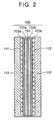
- FIG. 2 which is a sectional view, a membrane electrode assembly 100 that is configured by a pair of catalyst layers 102a, 102b pinching both sides of an electrolyte membrane 101, a pair of diffusion layers 103a, 103b that are placed on both sides of the membrane electrode assembly 100, and separators 110 that pinch these constitute the plurality of cells 10a.
- the electrolyte membrane 101 is a proton-conducting ion exchange membrane that is formed by the use of a hydrous polymer material such as fluorocarbon-based and hydrocarbon-based polymer materials.
- Each of the pair of catalyst layers 102a, 102b constitutes an electrode.
- the anode side catalyst layer 102a that constitutes an anode electrode and the cathode side catalyst layer 102b that constitutes a cathode electrode constitute the pair of catalyst layers 102a, 102b.
- materials (such as platinum particles) 102c that exert a catalytic action, carrying carbons 102d that carry the materials 102c, and an ionomer (electrolyte polymer) 102e that covers the carrying carbons 102d constitute each of the catalyst layers 102a, 102b.
- the diffusion layers 103a, 103b diffuse the reaction gas to the catalyst layers 102a, 102b, respectively.
- a porous member that has gas permeability and electron conductivity constitutes the diffusion layers 103a, 103b.
- An electrically conductive carbonaceous base material is an example of a material that constitutes the separator 110.
- a hydrogen flow path 111 through which the fuel gas flows is formed at a site of each of the separators 110 that faces the anode side catalyst layer 102a.
- An air flow path 112 through which the oxidant gas flows is formed at a site of each of the separators 110 that faces the cathode side catalyst layer 102b.
- each of the plurality of cells 10a outputs the electric energy, by the electrochemical reaction of the hydrogen gas and the oxygen gas, as follows. (Anode side) H 2 ⁇ 2H + +2e - (Cathode side) 2H++1/2O 2 +2e - ⁇ H 2 O
- the fuel cell 10 is electrically connected to the various electrical loads via the DC-DC converter 51a that is capable of bidirectional electric power supply.
- the DC-DC converter 51a, a voltage sensor 52a, and a current sensor 52b constitute a current control device 51.
- the DC-DC converter 51a controls an electric power flow from the fuel cell 10 to the various electrical loads or from the various electrical loads to the fuel cell 10.
- the diagnostic device 5 which diagnoses a deficiency of the hydrogen gas and a deficiency of the oxygen gas in the cells 10a, is connected to the fuel cell 10 according to this embodiment.
- the diagnostic device 5 will be described later.
- An air supply pipe 20 and an air discharge pipe 21 are connected to the fuel cell 10 that is illustrated in FIG. 1 .
- the air supply pipe 20 is to supply the air to an air inlet portion 11 a.
- the air discharge pipe 21 is to discharge the air, produced water, and impurities to the outside from an air outlet portion limb.
- the air inlet portion 11 a constitutes a gas inlet portion that supplies the oxidant gas to the air flow paths 112 of the plurality of cells 10a.
- the air outlet portion 11b constitutes a gas outlet portion that discharges the produced water, the impurities, and the air from the air flow paths 112 of the plurality of cells 10a.
- An air pump 22 is disposed in a most upstream portion of the air supply pipe 20.
- the air pump 22 is to pump the air suctioned from an atmosphere to the fuel cell 10.
- the air pump 22 is an electric pump.
- a compression mechanism that pumps the air and an electric motor that drives the compression mechanism constitute the air pump 22.
- An air pressure regulating valve 23 which adjusts a pressure of the air that is supplied to the fuel cell 10, is disposed on the air supply pipe 20 between the air pump 22 and the fuel cell 10.
- a valve body that adjusts a degree of opening of an air flow path in the air supply pipe 20 through which the air flows and an electric actuator that drives this valve body constitute the air pressure regulating valve 23.
- An electromagnetic valve 24 is disposed on the air discharge pipe 21.
- the electromagnetic valve 24 is to discharge, to the outside, the air, the produced water, the impurities, and the like present in the fuel cell 10.
- a valve body that adjusts a degree of opening of an air discharge passage in the air discharge pipe 21 through which the air is discharged and an electric actuator that drives this valve body constitute the electromagnetic valve 24.
- a hydrogen supply pipe 30 and a hydrogen discharge pipe 31 are connected to the fuel cell 10, too.
- the hydrogen supply pipe 30 has a hydrogen supply flow path for supply of hydrogen to a hydrogen inlet portion 12a.
- the hydrogen discharge pipe 31 is provided with a hydrogen discharge flow path for discharge of a very small amount of unreacted hydrogen or the like to the outside from a hydrogen outlet portion 12b.
- the hydrogen inlet portion 12a constitutes a gas inlet portion that supplies the fuel gas to the hydrogen flow paths 111 of the plurality of cells 10a.
- the hydrogen outlet portion 12b constitutes a gas outlet portion that discharges the unreacted hydrogen or the like from the hydrogen flow paths 111 of the plurality of cells 10a.
- a high-pressure hydrogen tank 32 filled with high-pressure hydrogen is disposed in a most upstream portion of the hydrogen supply pipe 30.
- a hydrogen pressure regulating valve 33 which adjusts a pressure of the hydrogen that is supplied to the fuel cell 10, is disposed on the hydrogen supply pipe 30 between the high-pressure hydrogen tank 32 and the fuel cell 10.
- a valve body that adjusts a degree of opening of the hydrogen supply flow path in the hydrogen supply pipe 30 and an electric actuator that drives this valve body constitute the hydrogen pressure regulating valve 33.
- An electromagnetic valve 34 is disposed on the hydrogen discharge pipe 31.
- the electromagnetic valve 34 is to discharge the very small amount of unreacted hydrogen or the like to the outside.
- a valve body that adjusts a degree of opening of the hydrogen discharge flow path in the hydrogen discharge pipe 31 and an electric actuator that drives this valve body constitute the electromagnetic valve 34.
- the pressure regulating valves 23, 33, the electromagnetic valves 24, 34, and the air pump 22 are controlled by the diagnostic device 5.
- a cooling water circulation circuit 4 through which cooling water circulates is also connected to the fuel cell 10 as a cooling system that adjusts a temperature of the fuel cell 10.
- a water pump 41 that circulates the cooling water and a radiator 42, which radiates the cooling water that has passed through the fuel cell 10 by heat exchange between the cooling water and outside air, are disposed in the cooling water circulation circuit 4.
- the radiator 42 cools the cooling water by using the outside air that is blown by an electric fan 43.
- a bypass flow path 44 is disposed in the cooling water circulation circuit 4, too.
- the bypass flow path 44 allows an inlet of the water pump 41 and a water outlet of the fuel cell 10 to be connected to each other by bypassing the radiator 42.
- Also disposed is a three-way valve 45 that connects either the bypass flow path 44 or a water outlet of the radiator 42 to the inlet of the water pump 41.
- FIG. 4 shows, in a perspective view, a part of the cells 10a constituting the fuel cell 10 so as to show an internal structure of the fuel cell 10.
- a microcomputer, a memory, a digital/analog converter, an analog/digital converter, and the like constitute the diagnostic device 5.
- an AC component ⁇ I addition unit 510, a ⁇ In calculation unit 540, a Zn calculation unit 520, and a diagnosis unit 530 are main components constituting the diagnostic device 5.
- the AC component ⁇ I addition unit 510 superimposes an alternating current of a low frequency f (AC component ⁇ I) on an output current of the fuel cell 10 through the DC-DC converter 51a.
- the DC-DC converter 51 a is connected to the fuel cell 10, and superimposes the alternating current from the AC component ⁇ I addition unit 510 on the output current of the fuel cell 10 as illustrated in FIG. 5 .
- each alternating current that is superimposed in the DC-DC converter 51a is within 10% of the output current (electric power generation current) of the fuel cell 10 in view of an electric power generation state of the fuel cell 10.
- the alternating current may change in accordance with the electric power generation state of the fuel cell 10, too.
- the AC component ⁇ I addition unit 510 may be configured to superimpose, through the DC-DC converter 51 a, alternating currents of a plurality of different frequencies on the output current (electric power generation current) of the fuel cell 10.
- the ⁇ In calculation unit 540 calculates an AC component ⁇ In of the low frequency f (that is, the alternating current of the low frequency f) in a total current I flowing through the fuel cell 10 based on a detection current I of the current sensor 52b.
- a method such as the fast Fourier transform is used when the ⁇ In calculation unit 540 according to this embodiment calculates the AC component ⁇ In.
- the current sensor 52b detects the total current I flowing through the fuel cell 10.
- the total current I is a current including the output current of the fuel cell 10 (detection current I in FIG. 5 ) and the alternating current of the low frequency f (AC component ⁇ I in FIG. 5 ).
- the Zn calculation unit 520 calculates, for each of the cells 10a, an AC component ⁇ V of the low frequency f (that is, an AC voltage of the low frequency f) in a cell voltage output from the cell 10a based on an output voltage of an amplification circuit 53.
- a method such as the fast Fourier transform is used when the Zn calculation unit 520 according to this embodiment calculates the AC component ⁇ V.
- the impedance of the cell 10a with respect to the alternating current will be referred to as a cell impedance.
- the amplification circuit 53 amplifies and outputs a voltage output from the cell monitor 54 for each of the cells 10a.
- the cell monitor 54 is voltage detection means for detecting voltages output from the cells 10a for each of the cells 10a. Accordingly, the amplification circuit 53 amplifies each of the cell voltages output from the plurality of cells 10a.
- the voltage sensor 52a detects the voltage output from the fuel cell 10 as a whole (that is, all of the plurality of cells 10a). Hereinafter, this voltage will be referred to as a total voltage.
- the Zn calculation unit 520 calculates an AC component V of the low frequency f (that is, the AC voltage of the low frequency f) in the total voltage based on a detection voltage of the voltage sensor 52a.
- a method such as the fast Fourier transform is used when the Zn calculation unit 520 according to this embodiment calculates the AC component V.
- the Zn calculation unit 520 calculates an impedance of the entire fuel cell 10 (that is, all of the plurality of cells 10a) with respect to the alternating current (hereinafter, referred to as a stack overall impedance ⁇ Zn) by dividing the "AC component V” by the "AC component ⁇ In calculated by the ⁇ In calculation unit 540".
- the diagnosis unit 530 diagnoses the deficiency of the hydrogen gas and the deficiency of the oxygen gas with regard to any of the cells 10a by comparing an absolute value of the cell impedance of each of the cells 10a to an absolute value of a reference impedance.
- a reaction in an air electrode (cathode) changes to a carbon oxidation reaction from an oxygen reduction reaction at a time of normal electric power generation.
- the cell 10a subjected to the deficiency of the hydrogen gas will be referred to as a hydrogen gas-deficient cell.
- a reaction resistance of the hydrogen gas-deficient cell becomes far greater than a reaction resistance of the cell 10a having the oxygen reduction reaction. Accordingly, the absolute value of the cell impedance of the hydrogen gas-deficient cell becomes greater than the absolute value of the cell impedance of the cell 10a having the oxygen reduction reaction.
- the absolute value of the cell impedance of the cell 10a at a time of hydrogen deficiency becomes greater than the absolute value of the cell impedance of the cell 10a at the time of the normal electric power generation (refer to FIG. 6 ).
- the time of the normal electric power generation refers to a no-deficiency state where the hydrogen gas and the oxygen gas are sufficiently supplied to the cell 10a at a time when the electric power generation is performed by the cell 10a.
- the reaction in the air electrode changes to a hydrogen pumping reaction from the oxygen reduction reaction at the time of the normal electric power generation.
- the cell 10a subjected to the deficiency of the oxygen gas will be referred to as an oxygen-deficient cell.
- the high-frequency impedance refers to an impedance of the cell 10a with respect to a high-frequency alternating current when an alternating current of high frequency (such as 1 kHz) is superimposed on the output current of the fuel cell 10.
- the absolute value of the impedance of the cell 10a at a time of air (oxygen gas) deficiency becomes smaller than the absolute value of the impedance of the cell 10a at the time of the normal electric power generation (refer to FIG. 7 ).
- the AC component ⁇ I addition unit 510 superimposes, through the DC-DC converter 51 a, the alternating current of the low frequency f (AC component ⁇ I) on the output current (electric power generation current) of the fuel cell 10.
- the ⁇ In calculation unit 540 calculates the AC component ⁇ In of the low frequency f in the total current I flowing through the fuel cell 10 based on the detection current I of the current sensor 52b.
- the cell monitor 54 detects the output voltages ⁇ V of the cells 10a for each of the cells 10a.
- the amplification circuit 53 amplifies and outputs each of the output voltages ⁇ V of the respective cells 10a output from the cell monitor 54.
- the Zn calculation unit 520 calculates the cell impedance of each of the cells 10a based on the output voltage of the amplification circuit 53 and the AC component ⁇ In calculated by the ⁇ In calculation unit 540.
- the Zn calculation unit 520 calculates the stack overall impedance based on the total voltage detected by the voltage sensor 52a and the AC component ⁇ In calculated by the ⁇ In calculation unit 540.
- the diagnosis unit 530 diagnoses whether any of the cells 10a is deficient in the hydrogen gas and the oxygen gas based on the stack overall impedance and the cell impedance of each of the cells 10a.
- the diagnosis unit 530 executes the diagnosis processing in accordance with a flowchart that is illustrated in FIG. 8.
- FIG. 8 is the flowchart illustrating the diagnosis processing that is executed by the diagnosis unit 530.
- Step 100 the reference impedance is calculated that is used for the diagnosis of whether the cell 10a is deficient in the hydrogen gas and the oxygen gas.
- the reference impedance is the impedance of the reference cell 10a, which is one of the plurality of cells 10a that is selected in advance.
- the reference cell 10a is one of the plurality of cells 10a that is selected in advance, in which it is assumed that the deficiency of the hydrogen gas and the deficiency of the oxygen gas are unlikely to occur. The selection of the reference cell 10a will be described later.
- An average value that is obtained by the stack overall impedance ⁇ Zn being divided by the number N of the cells 10a may be used, instead of the impedance of the reference cell 10a, as the reference impedance.
- Step 110 (absolute value of the reference impedance + a predetermined value P) is obtained by the predetermined value ⁇ being added to the absolute value of the reference impedance, and it is determined whether the absolute value of the cell impedance of any of the cells 10a exceeds the (absolute value of the reference impedance + the predetermined value ⁇ ).
- Any of the cells 10a is any one of the plurality of cells 10a.
- the predetermined value ⁇ is a value that is determined in advance for a threshold to be compared to the absolute value of the cell impedance to be adjusted.
- Step 110 When the absolute value of the cell impedance of any of the cells 10a exceeds the (absolute value of the reference impedance + the predetermined value ⁇ ), for example, a YES determination is made in Step 110. At this time, it is diagnosed that any of the cells 10a is in a state of the hydrogen gas deficiency.
- the fuel cell 10 is subjected to a feedback control so that the state of the hydrogen deficiency of any of the cells 10a is avoided. Specifically, a degree of opening of the hydrogen pressure regulating valve 33 is increased and a degree of opening of the electromagnetic valve 34 is increased.
- the amount of the fuel gas supplied from the high-pressure hydrogen tank 32 to the plurality of cells 10a (that is, the hydrogen gas) can be increased. Accordingly, the amount of the hydrogen gas supplied to any of the cells 10a can be increased. In this manner, the state of the hydrogen gas deficiency of any of the cells 10a can be avoided. Subsequently, the processing proceeds to Step 130.
- a rotation speed of an electric pump for fuel gas circulation may be increased in a system that has the electric pump for fuel gas circulation for fuel gas pumping with respect to the fuel cell 10. This allows the amount of the hydrogen gas supplied from the high-pressure hydrogen tank 32 to the plurality of cells 10a to increase and the deficiency of the hydrogen gas to be avoided.
- Step 110 A NO determination is made in Step 110 when the absolute value of the cell impedance of any of the cells 10a is smaller than the (absolute value of the reference impedance + the predetermined value ⁇ ). At this time, it is diagnosed that none of the cells 10a is in the state of the hydrogen gas deficiency. The processing proceeds to Step 130 in this case, too.
- Step 130 (absolute value of the reference impedance-a predetermined value ⁇ ) is obtained by the predetermined value ⁇ being subtracted from the absolute value of the reference impedance, and it is determined whether the absolute value of the cell impedance of any of the cells 10a is smaller than the (absolute value of the reference impedance-the predetermined value ⁇ ).
- the predetermined value ⁇ is a value that is determined in advance for the threshold to be compared to the absolute value of the cell impedance to be adjusted.
- Step 130 When the absolute value of the cell impedance of any of the cells 10a is smaller than the (absolute value of the reference impedance-the predetermined value ⁇ ), for example, a YES determination is made in Step 130. At this time, it is diagnosed that any of the cells 10a is in a state of the oxygen gas deficiency.
- the fuel cell 10 is subjected to a feedback control so that the state of the oxygen deficiency of any of the cells 10a is avoided.
- the amount of the air blown from the air pump 22 that is, the amount of the oxygen gas that is supplied
- the amount of the oxygen gas that is supplied is increased by a rotation speed of the electric motor of the air pump 22 being increased. Accordingly, the deficiency of the oxygen gas can be avoided.
- a degree of opening of the air pressure regulating valve 23 is increased and a degree of opening of the electromagnetic valve 24 is increased. Accordingly, the deficiency of the oxygen gas can be avoided, because water inhibiting oxygen gas transport is removed by a volumetric flow rate of the air blown from the air pump 22 being increased.
- the state of the oxygen gas deficiency of any of the cells 10a can be avoided by the amount of the air (that is, the oxygen gas) supplied to any of the cells 10a being increased.
- This diagnosis processing is carried out for each of the plurality of cells 10a.
- a hydrogen gas deficiency avoidance control (Step 120) is carried out. Then, the deficiency of the hydrogen gas can be avoided.
- an oxygen gas deficiency avoidance control (Step 140) is carried out. Then, the deficiency of the oxygen gas can be avoided.
- both the hydrogen gas deficiency avoidance control (Step 120) and the oxygen gas deficiency avoidance control (Step 140) are carried out. Then, the deficiency of the hydrogen gas and the deficiency of the oxygen gas can be avoided.
- the AC component ⁇ I addition unit 510 superimposes the alternating current on the output current of the fuel cell 10 in the diagnostic device that diagnoses the state of the fuel cell 10 in which the plurality of cells 10a are stacked to generate the electric energy by using the electrochemical reaction of the oxygen gas and the hydrogen gas.
- the cell monitor 54 detects the output voltage ⁇ V of each of the cells 10a.
- the ⁇ In calculation unit 540 detects the total current flowing through the plurality of cells 10a.
- the Zn calculation unit 520 calculates the cell impedance with respect to the alternating current with regard to any of the plurality of cells 10a.
- the absolute value of the impedance of the cell 10a at the time of the hydrogen deficiency becomes greater than the absolute value of the impedance of the cell 10a at the time of the normal electric power generation.
- the time of the normal electric power generation refers to the no-deficiency state where the hydrogen gas and the oxygen gas are sufficiently supplied to the cell 10a at a time when the electrochemical reaction is performed by the cell 10a.
- the diagnostic device 5 can diagnose that any of the cells 10a is in the state of the hydrogen gas deficiency when it is determined that the absolute value of the cell impedance of any of the cells 10a exceeds the (absolute value of the reference impedance + the predetermined value ⁇ ).
- the absolute value of the impedance of the cell 10a at the time of the oxygen gas deficiency becomes smaller than the absolute value of the impedance of the cell 10a at the time of the normal electric power generation.
- the diagnostic device 5 can diagnose that any of the cells 10a is in the state of the oxygen gas deficiency when it is determined that the absolute value of the cell impedance is smaller than the (absolute value of the reference impedance-the predetermined value ⁇ ).
- the diagnostic device 5 can diagnose that any of the cells 10a is in the state of the hydrogen gas deficiency by comparing the absolute value of the reference impedance to the absolute value of the cell impedance and without using the amount of a decrease in the output voltage of the cell 10a.
- the diagnostic device 5 diagnoses that the cell 10a is subjected to the deficiency of the hydrogen gas, the deficiency of the hydrogen gas of the cell 10a can be avoided by the fuel cell 10 being controlled.
- the diagnostic device 5 diagnoses that the cell 10a is subjected to the deficiency of the oxygen gas, the deficiency of the oxygen gas of the cell 10a can be avoided by the fuel cell 10 being controlled.
- the diagnostic device 5 diagnoses that the cell 10a is subjected to the deficiency of the oxygen gas and the deficiency of the hydrogen gas, the deficiency of the oxygen gas and the deficiency of the hydrogen gas of the cell 10a can be avoided by the fuel cell 10 being controlled.
- the reference cell 10a for hydrogen gas deficiency diagnosis can be selected as follows. For example, one of the plurality of cells 10a that is likely to have a highest fuel gas (hydrogen gas) flow velocity can be selected as the reference cell 10a. More specifically, one of the plurality of cells 10a that is on an upstream side in a fuel gas flow direction (that is, on the high-pressure hydrogen tank 32 side) is likely to have the highest fuel gas (hydrogen gas) flow velocity, and thus this cell 10a on the upstream side in the fuel gas flow direction can be selected as the reference cell 10a.
- one of the plurality of cells 10a that is on a central side in a cell stacking direction can be selected as the reference cell 10a.
- One of the plurality of cells 10a that is on an end side in the cell stacking direction is likely to be subjected to radiation, and thus is likely to be subjected to water clogging in the hydrogen flow path 111 and the deficiency of the hydrogen gas.
- the one of the plurality of cells 10a that is on the central side in the cell stacking direction is less likely to be subjected to radiation, and thus is less likely to be subjected to the deficiency of the hydrogen gas attributable to water clogging.
- the reference cell 10a for oxygen gas deficiency diagnosis can be selected as follows. For example, one of the plurality of cells 10a that is likely to have a highest air (oxygen gas) flow velocity can be selected as the reference cell 10a. More specifically, one of the plurality of cells 10a in the fuel cell 10 that is on an upstream side in an air flow direction (that is, on the air pump 22 side) is likely to have the highest air flow velocity, and thus this cell 10a on the upstream side in the air flow direction can be selected as the reference cell 10a.
- one of the plurality of cells 10a that is on the central side in the cell stacking direction can be selected as the reference cell 10a.
- One of the plurality of cells 10a that is on the end side in the cell stacking direction is likely to be subjected to radiation, and thus is likely to be subjected to water clogging in the air flow path 112 and the deficiency of the oxygen gas.
- the one of the plurality of cells 10a that is on the central side in the cell stacking direction is less likely to be subjected to the deficiency of the oxygen gas attributable to the water clogging in the air flow path 112.
- Step 100 can be regarded as second calculation means
- Step 110 can be regarded as first determination means
- Step 130 can be regarded as second determination means and third determination means
- Step 120 can be regarded as first control means.
- the hydrogen pressure regulating valve 33 and the electromagnetic valve 34 can be regarded as first adjustment means
- the air pump 22, the air pressure regulating valve 23, and the electromagnetic valve 24 can be regarded as second adjustment means
- Step 140 can be regarded as second control means.
Landscapes
- Engineering & Computer Science (AREA)
- Chemical Kinetics & Catalysis (AREA)
- Life Sciences & Earth Sciences (AREA)
- Manufacturing & Machinery (AREA)
- Sustainable Development (AREA)
- Sustainable Energy (AREA)
- Chemical & Material Sciences (AREA)
- Electrochemistry (AREA)
- General Chemical & Material Sciences (AREA)
- Physics & Mathematics (AREA)
- General Physics & Mathematics (AREA)
- Power Engineering (AREA)
- Fuel Cell (AREA)
Abstract
Description
- The invention relates to a diagnostic device that diagnoses a state of a fuel cell.
- A fuel cell system is known that is provided with a fuel cell in which a plurality of cells generating electric energy by using an electrochemical reaction of an oxygen gas and a hydrogen gas are stacked and an output control unit which generates an alternating current and an AC voltage in an output of the fuel cell (for example, refer to Japanese Patent Application Publication No.
2013-140715 JP 2013-140715 A - This fuel cell system is provided with an impedance calculation unit and a hydrogen concentration calculation unit. The impedance calculation unit obtains an absolute value of an internal impedance of the fuel cell as a whole based on the alternating current and the AC voltage output from the fuel cell. The hydrogen concentration calculation unit calculates a hydrogen concentration of the fuel cell based on the absolute value of the internal impedance of the fuel cell.
- In addition, in a fuel cell system that is disclosed in Japanese Patent Application Publication No.
2012-252986 JP 2012-252986 A - Specifically, the impedance of any of the cells is measured, and then it is diagnosed that the cell is deficient in either the oxygen gas or the hydrogen gas when an absolute value of the measured impedance has increased. In addition, it is determined, in accordance with the amount of the decrease in the output voltage of the cell, whether the cell is deficient in the oxygen gas or the hydrogen gas.
- In the fuel cell system that is disclosed in
JP 2013-140715 A - The fuel cell system that is disclosed in
JP 2012-252986 A - The invention provides a diagnostic device that diagnoses whether any cell is deficient in a hydrogen gas or an oxygen gas without using the amount of a decrease in an output voltage of the cell.
- A first aspect of the invention relates to a diagnostic device diagnosing a state of a fuel cell in which a plurality of cells generating electric energy by using an electrochemical reaction of an oxidizing agent containing oxygen and a fuel containing hydrogen are stacked. The diagnostic device includes signal superimposition means for superimposing an alternating current on an output current of the fuel cell, first voltage detection means for detecting each of voltages output from the respective cells, second voltage detection means for detecting a voltage output from the fuel cell, current detection means for obtaining a current flowing through the plurality of cells, first calculation means for calculating a first low-frequency impedance with respect to the alternating current with regard to any of the plurality of cells based on the current detected by the current detection means and the voltage detected by the first voltage detection means, second calculation means for calculating a second low-frequency impedance of the entire fuel cell with respect to the alternating current or a third low-frequency impedance with respect to the alternating current with regard to a reference cell selected in advance among the plurality of cells as one of the cells in which a hydrogen deficiency is unlikely to occur based on the current detected by the current detection means and the voltages detected by the first and second voltage detection means and calculating a reference impedance based on the calculated second or third low-frequency impedance, and first determination means for determining whether an absolute value of the first low-frequency impedance calculated by the first calculation means exceeds an absolute value of the reference impedance, in which the first determination means diagnoses that any cell is in a state of the hydrogen deficiency when the first determination means determines that the absolute value of the first low-frequency impedance calculated by the first calculation means exceeds the absolute value of the reference impedance.
- According to this diagnostic device, it can be diagnosed whether any of the cells is in the state of the hydrogen deficiency by the reference impedance being compared to the cell impedance and without the amount of a decrease in an output voltage of the cell being used.
- A frequency within a range of 1 Hz to 200 Hz, for example, is used as the low frequency.
- A second aspect of the invention relates to a diagnostic device diagnosing a state of a fuel cell in which a plurality of cells generating electric energy by using an electrochemical reaction of an oxidizing agent containing oxygen and a fuel containing hydrogen are stacked. The diagnostic device includes signal superimposition means for superimposing an alternating current on an output current of the fuel cell, first voltage detection means for detecting each of voltages output from the respective cells, second voltage detection means for detecting a voltage output from the fuel cell, current detection means for obtaining a current flowing through the plurality of cells, first calculation means for calculating a first low-frequency impedance with respect to the alternating current with regard to any of the plurality of cells based on the current detected by the current detection means and the voltage detected by the first voltage detection means, second calculation means for calculating a second low-frequency impedance of the entire fuel cell with respect to the alternating current or a third low-frequency impedance with respect to the alternating current with regard to a reference cell selected in advance among the plurality of cells as one of the cells in which an oxygen deficiency is unlikely to occur based on the current detected by the current detection means and the voltages detected by the first and second voltage detection means and calculating a reference impedance based on the calculated second or third low-frequency impedance, and third determination means for determining whether an absolute value of the first low-frequency impedance calculated by the first calculation means is smaller than an absolute value of the reference impedance, in which the first determination means diagnoses that any cell is in a state of the oxygen deficiency when the third determination means determines that the absolute value of the first low-frequency impedance calculated by the first calculation means is smaller than the absolute value of the reference impedance.
- According to this diagnostic device, it can be diagnosed whether any of the cells is in the state of the oxygen deficiency by the reference impedance being compared to the cell impedance and without the amount of a decrease in an output voltage of the cell being used.
- Features, advantages, and technical and industrial significance of exemplary embodiments of the invention will be described below with reference to the accompanying drawings, in which like numerals denote like elements, and wherein:
-
FIG. 1 is an overall configuration diagram illustrating a fuel cell system according to an embodiment of the invention; -
FIG. 2 is a schematic sectional view of a single cell according to the embodiment; -
FIG. 3 is a schematic sectional view illustrating an internal structure of the single cell according to the embodiment; -
FIG. 4 is a schematic diagram illustrating a diagnostic device according to the embodiment; -
FIG. 5 is an explanatory diagram for showing an alternating current that is superimposed on an output current of a fuel cell by a signal superimposition unit according to the embodiment; -
FIG. 6 is a histogram in which a cell impedance at a time of hydrogen deficiency and a cell impedance at a time of normal electric power generation are compared to each other according to the embodiment; -
FIG. 7 is a histogram in which a cell impedance at a time of air deficiency (oxygen deficiency) and the cell impedance at the time of the normal electric power generation are compared to each other according to the embodiment; and -
FIG. 8 is a flowchart illustrating a fuel cell diagnosis processing that is executed by the diagnostic device according to the embodiment. - Hereinafter, a
fuel cell system 1 to which adiagnostic device 5 according to an embodiment of the invention is applied will be described with reference to accompanying drawings. Thediagnostic device 5 according to this embodiment is applied to a fuel cell vehicle as a type of electric car. Thediagnostic device 5 according to this embodiment diagnoses a state of afuel cell 10 that is mounted in the vehicle. - The
fuel cell 10 outputs electric energy by using an electrochemical reaction of reaction gases such as a fuel gas including a hydrogen gas and an oxidant gas including an oxygen gas (air in this example). In this embodiment, a solid polymer-type fuel cell is adopted as thefuel cell 10. - As illustrated in
FIG. 1 , which is an overall configuration diagram, thefuel cell 10 supplies DC electric power that is generated by electric power generation to electrical loads (not illustrated), such as an electric motor mainly for vehicle traveling and a secondary battery, via a DC-DC converter 51a. - The
fuel cell 10 according to this embodiment is a stack structure in which a plurality ofcells 10a are stacked as minimum units. Thefuel cell 10 according to this embodiment is configured as a serial connection body in which the plurality ofcells 10a are electrically connected in series. - As illustrated in
FIG. 2 , which is a sectional view, amembrane electrode assembly 100 that is configured by a pair ofcatalyst layers electrolyte membrane 101, a pair ofdiffusion layers membrane electrode assembly 100, andseparators 110 that pinch these constitute the plurality ofcells 10a. - The
electrolyte membrane 101 is a proton-conducting ion exchange membrane that is formed by the use of a hydrous polymer material such as fluorocarbon-based and hydrocarbon-based polymer materials. - Each of the pair of
catalyst layers side catalyst layer 102a that constitutes an anode electrode and the cathodeside catalyst layer 102b that constitutes a cathode electrode constitute the pair ofcatalyst layers FIG. 3 , which is a schematic diagram, materials (such as platinum particles) 102c that exert a catalytic action, carryingcarbons 102d that carry thematerials 102c, and an ionomer (electrolyte polymer) 102e that covers thecarrying carbons 102d constitute each of thecatalyst layers - The
diffusion layers catalyst layers diffusion layers - An electrically conductive carbonaceous base material is an example of a material that constitutes the
separator 110. Ahydrogen flow path 111 through which the fuel gas flows is formed at a site of each of theseparators 110 that faces the anodeside catalyst layer 102a. Anair flow path 112 through which the oxidant gas flows is formed at a site of each of theseparators 110 that faces the cathodeside catalyst layer 102b. - Once the fuel gas and the oxidant gas are supplied, each of the plurality of
cells 10a outputs the electric energy, by the electrochemical reaction of the hydrogen gas and the oxygen gas, as follows.
(Anode side) H2→2H++2e-
(Cathode side) 2H++1/2O2+2e-→H2O
- Referring back to
FIG. 1 , thefuel cell 10 is electrically connected to the various electrical loads via the DC-DC converter 51a that is capable of bidirectional electric power supply. The DC-DC converter 51a, avoltage sensor 52a, and acurrent sensor 52b constitute acurrent control device 51. The DC-DC converter 51a controls an electric power flow from thefuel cell 10 to the various electrical loads or from the various electrical loads to thefuel cell 10. - The
diagnostic device 5, which diagnoses a deficiency of the hydrogen gas and a deficiency of the oxygen gas in thecells 10a, is connected to thefuel cell 10 according to this embodiment. Thediagnostic device 5 will be described later. - An
air supply pipe 20 and anair discharge pipe 21 are connected to thefuel cell 10 that is illustrated inFIG. 1 . Theair supply pipe 20 is to supply the air to anair inlet portion 11 a. Theair discharge pipe 21 is to discharge the air, produced water, and impurities to the outside from an air outlet portion limb. - The
air inlet portion 11 a constitutes a gas inlet portion that supplies the oxidant gas to theair flow paths 112 of the plurality ofcells 10a. Theair outlet portion 11b constitutes a gas outlet portion that discharges the produced water, the impurities, and the air from theair flow paths 112 of the plurality ofcells 10a. - An air pump 22 is disposed in a most upstream portion of the
air supply pipe 20. The air pump 22 is to pump the air suctioned from an atmosphere to thefuel cell 10. The air pump 22 is an electric pump. A compression mechanism that pumps the air and an electric motor that drives the compression mechanism constitute the air pump 22. - An air
pressure regulating valve 23, which adjusts a pressure of the air that is supplied to thefuel cell 10, is disposed on theair supply pipe 20 between the air pump 22 and thefuel cell 10. A valve body that adjusts a degree of opening of an air flow path in theair supply pipe 20 through which the air flows and an electric actuator that drives this valve body constitute the airpressure regulating valve 23. - An
electromagnetic valve 24 is disposed on theair discharge pipe 21. Theelectromagnetic valve 24 is to discharge, to the outside, the air, the produced water, the impurities, and the like present in thefuel cell 10. A valve body that adjusts a degree of opening of an air discharge passage in theair discharge pipe 21 through which the air is discharged and an electric actuator that drives this valve body constitute theelectromagnetic valve 24. - A
hydrogen supply pipe 30 and ahydrogen discharge pipe 31 are connected to thefuel cell 10, too. Thehydrogen supply pipe 30 has a hydrogen supply flow path for supply of hydrogen to ahydrogen inlet portion 12a. Thehydrogen discharge pipe 31 is provided with a hydrogen discharge flow path for discharge of a very small amount of unreacted hydrogen or the like to the outside from ahydrogen outlet portion 12b. - The
hydrogen inlet portion 12a constitutes a gas inlet portion that supplies the fuel gas to thehydrogen flow paths 111 of the plurality ofcells 10a. Thehydrogen outlet portion 12b constitutes a gas outlet portion that discharges the unreacted hydrogen or the like from thehydrogen flow paths 111 of the plurality ofcells 10a. - A high-
pressure hydrogen tank 32 filled with high-pressure hydrogen is disposed in a most upstream portion of thehydrogen supply pipe 30. A hydrogenpressure regulating valve 33, which adjusts a pressure of the hydrogen that is supplied to thefuel cell 10, is disposed on thehydrogen supply pipe 30 between the high-pressure hydrogen tank 32 and thefuel cell 10. A valve body that adjusts a degree of opening of the hydrogen supply flow path in thehydrogen supply pipe 30 and an electric actuator that drives this valve body constitute the hydrogenpressure regulating valve 33. - An
electromagnetic valve 34 is disposed on thehydrogen discharge pipe 31. Theelectromagnetic valve 34 is to discharge the very small amount of unreacted hydrogen or the like to the outside. A valve body that adjusts a degree of opening of the hydrogen discharge flow path in thehydrogen discharge pipe 31 and an electric actuator that drives this valve body constitute theelectromagnetic valve 34. - In this embodiment, the
pressure regulating valves electromagnetic valves diagnostic device 5. - A cooling
water circulation circuit 4 through which cooling water circulates is also connected to thefuel cell 10 as a cooling system that adjusts a temperature of thefuel cell 10. Awater pump 41 that circulates the cooling water and aradiator 42, which radiates the cooling water that has passed through thefuel cell 10 by heat exchange between the cooling water and outside air, are disposed in the coolingwater circulation circuit 4. Theradiator 42 cools the cooling water by using the outside air that is blown by anelectric fan 43. - A
bypass flow path 44 is disposed in the coolingwater circulation circuit 4, too. Thebypass flow path 44 allows an inlet of thewater pump 41 and a water outlet of thefuel cell 10 to be connected to each other by bypassing theradiator 42. Also disposed is a three-way valve 45 that connects either thebypass flow path 44 or a water outlet of theradiator 42 to the inlet of thewater pump 41. - Hereinafter, the
diagnostic device 5 according to this embodiment will be described with reference toFIG. 4. FIG. 4 shows, in a perspective view, a part of thecells 10a constituting thefuel cell 10 so as to show an internal structure of thefuel cell 10. - A microcomputer, a memory, a digital/analog converter, an analog/digital converter, and the like constitute the
diagnostic device 5. Specifically, an AC componentΔI addition unit 510, aΔIn calculation unit 540, aZn calculation unit 520, and adiagnosis unit 530 are main components constituting thediagnostic device 5. - The AC component
ΔI addition unit 510 superimposes an alternating current of a low frequency f (AC component ΔI) on an output current of thefuel cell 10 through the DC-DC converter 51a. The DC-DC converter 51 a is connected to thefuel cell 10, and superimposes the alternating current from the AC componentΔI addition unit 510 on the output current of thefuel cell 10 as illustrated inFIG. 5 . A frequency within a range of 1 Hz to 200 Hz, for example, is used as the low frequency f according to this embodiment. - It is desirable that each alternating current that is superimposed in the DC-
DC converter 51a is within 10% of the output current (electric power generation current) of thefuel cell 10 in view of an electric power generation state of thefuel cell 10. The alternating current may change in accordance with the electric power generation state of thefuel cell 10, too. - In addition, the AC component
ΔI addition unit 510 may be configured to superimpose, through the DC-DC converter 51 a, alternating currents of a plurality of different frequencies on the output current (electric power generation current) of thefuel cell 10. - The
ΔIn calculation unit 540 calculates an AC component ΔIn of the low frequency f (that is, the alternating current of the low frequency f) in a total current I flowing through thefuel cell 10 based on a detection current I of thecurrent sensor 52b. A method such as the fast Fourier transform is used when theΔIn calculation unit 540 according to this embodiment calculates the AC component ΔIn. - The
current sensor 52b detects the total current I flowing through thefuel cell 10. The total current I is a current including the output current of the fuel cell 10 (detection current I inFIG. 5 ) and the alternating current of the low frequency f (AC component ΔI inFIG. 5 ). - The
Zn calculation unit 520 calculates, for each of thecells 10a, an AC component ΔV of the low frequency f (that is, an AC voltage of the low frequency f) in a cell voltage output from thecell 10a based on an output voltage of anamplification circuit 53. A method such as the fast Fourier transform is used when theZn calculation unit 520 according to this embodiment calculates the AC component ΔV. - In addition, the
Zn calculation unit 520 calculates, for each of thecells 10a, an impedance of thecell 10a with respect to the alternating current by dividing the "AC component ΔV" by the "AC component ΔIn calculated by theΔIn calculation unit 540" (=ΔV/ΔIn). Hereinafter, the impedance of thecell 10a with respect to the alternating current will be referred to as a cell impedance. - The
amplification circuit 53 amplifies and outputs a voltage output from the cell monitor 54 for each of thecells 10a. The cell monitor 54 is voltage detection means for detecting voltages output from thecells 10a for each of thecells 10a. Accordingly, theamplification circuit 53 amplifies each of the cell voltages output from the plurality ofcells 10a. - The
voltage sensor 52a detects the voltage output from thefuel cell 10 as a whole (that is, all of the plurality ofcells 10a). Hereinafter, this voltage will be referred to as a total voltage. - The
Zn calculation unit 520 calculates an AC component V of the low frequency f (that is, the AC voltage of the low frequency f) in the total voltage based on a detection voltage of thevoltage sensor 52a. A method such as the fast Fourier transform is used when theZn calculation unit 520 according to this embodiment calculates the AC component V. - Furthermore, the
Zn calculation unit 520 calculates an impedance of the entire fuel cell 10 (that is, all of the plurality ofcells 10a) with respect to the alternating current (hereinafter, referred to as a stack overall impedance ∑Zn) by dividing the "AC component V" by the "AC component ΔIn calculated by theΔIn calculation unit 540". - The
diagnosis unit 530 diagnoses the deficiency of the hydrogen gas and the deficiency of the oxygen gas with regard to any of thecells 10a by comparing an absolute value of the cell impedance of each of thecells 10a to an absolute value of a reference impedance. - Hereinafter, a principle of the diagnosis of the deficiency of the hydrogen gas and the deficiency of the oxygen gas in the
fuel cell system 1 according to this embodiment that is based on the comparison between the absolute value of the cell impedance and the absolute value of the reference impedance will be described. - When the deficiency of the hydrogen gas is caused during the electric power generation by the
cell 10a, a reaction in an air electrode (cathode) changes to a carbon oxidation reaction from an oxygen reduction reaction at a time of normal electric power generation. Hereinafter, thecell 10a subjected to the deficiency of the hydrogen gas will be referred to as a hydrogen gas-deficient cell. - At this time, a reaction resistance of the hydrogen gas-deficient cell becomes far greater than a reaction resistance of the
cell 10a having the oxygen reduction reaction. Accordingly, the absolute value of the cell impedance of the hydrogen gas-deficient cell becomes greater than the absolute value of the cell impedance of thecell 10a having the oxygen reduction reaction. - Accordingly, the absolute value of the cell impedance of the
cell 10a at a time of hydrogen deficiency becomes greater than the absolute value of the cell impedance of thecell 10a at the time of the normal electric power generation (refer toFIG. 6 ). The time of the normal electric power generation refers to a no-deficiency state where the hydrogen gas and the oxygen gas are sufficiently supplied to thecell 10a at a time when the electric power generation is performed by thecell 10a. - By the above, it is determined whether the absolute value of the cell impedance of any of the
cells 10a exceeds the absolute value of the reference impedance with the absolute value of the cell impedance of thecell 10a at the time of the normal electric power generation being used as the reference impedance. Then, it can be diagnosed whether any of thecells 10a is subjected to the deficiency of the hydrogen gas. - When the deficiency of the oxygen gas is caused during the electric power generation by the
cell 10a, the reaction in the air electrode changes to a hydrogen pumping reaction from the oxygen reduction reaction at the time of the normal electric power generation. Hereinafter, thecell 10a subjected to the deficiency of the oxygen gas will be referred to as an oxygen-deficient cell. - At this time, a reaction resistance relating to oxygen diffusion disappears in the oxygen-deficient cell, and thus the cell impedance of the oxygen-deficient cell becomes a value close to a high-frequency impedance and the absolute value of the impedance of the oxygen-deficient cell becomes smaller than the absolute value of the impedance of the
cell 10a having the oxygen reduction reaction. - The high-frequency impedance refers to an impedance of the
cell 10a with respect to a high-frequency alternating current when an alternating current of high frequency (such as 1 kHz) is superimposed on the output current of thefuel cell 10. - The absolute value of the impedance of the
cell 10a at a time of air (oxygen gas) deficiency becomes smaller than the absolute value of the impedance of thecell 10a at the time of the normal electric power generation (refer toFIG. 7 ). - By the above, it can be diagnosed whether any of the
cells 10a is subjected to the deficiency of the oxygen gas by whether the absolute value of the cell impedance of any of thecells 10a is smaller than the absolute value of the reference impedance being determined. - Hereinafter, an operation of the
fuel cell system 1 according to this embodiment will be described. - Firstly, the AC component
ΔI addition unit 510 superimposes, through the DC-DC converter 51 a, the alternating current of the low frequency f (AC component ΔI) on the output current (electric power generation current) of thefuel cell 10. - The
ΔIn calculation unit 540 calculates the AC component ΔIn of the low frequency f in the total current I flowing through thefuel cell 10 based on the detection current I of thecurrent sensor 52b. - The cell monitor 54 detects the output voltages ΔV of the
cells 10a for each of thecells 10a. Theamplification circuit 53 amplifies and outputs each of the output voltages ΔV of therespective cells 10a output from thecell monitor 54. - The
Zn calculation unit 520 calculates the cell impedance of each of thecells 10a based on the output voltage of theamplification circuit 53 and the AC component ΔIn calculated by theΔIn calculation unit 540. - The
Zn calculation unit 520 calculates the stack overall impedance based on the total voltage detected by thevoltage sensor 52a and the AC component ΔIn calculated by theΔIn calculation unit 540. - At this time, the
diagnosis unit 530 diagnoses whether any of thecells 10a is deficient in the hydrogen gas and the oxygen gas based on the stack overall impedance and the cell impedance of each of thecells 10a. - Specifically, the
diagnosis unit 530 executes the diagnosis processing in accordance with a flowchart that is illustrated inFIG. 8. FIG. 8 is the flowchart illustrating the diagnosis processing that is executed by thediagnosis unit 530. - Firstly, in
Step 100, the reference impedance is calculated that is used for the diagnosis of whether thecell 10a is deficient in the hydrogen gas and the oxygen gas. - The reference impedance is the impedance of the
reference cell 10a, which is one of the plurality ofcells 10a that is selected in advance. Thereference cell 10a is one of the plurality ofcells 10a that is selected in advance, in which it is assumed that the deficiency of the hydrogen gas and the deficiency of the oxygen gas are unlikely to occur. The selection of thereference cell 10a will be described later. - An average value that is obtained by the stack overall impedance ΣZn being divided by the number N of the
cells 10a (=∑Zn/N) may be used, instead of the impedance of thereference cell 10a, as the reference impedance. - Then, in
Step 110, (absolute value of the reference impedance + a predetermined value P) is obtained by the predetermined value β being added to the absolute value of the reference impedance, and it is determined whether the absolute value of the cell impedance of any of thecells 10a exceeds the (absolute value of the reference impedance + the predetermined value β). Any of thecells 10a is any one of the plurality ofcells 10a. The predetermined value β is a value that is determined in advance for a threshold to be compared to the absolute value of the cell impedance to be adjusted. - When the absolute value of the cell impedance of any of the
cells 10a exceeds the (absolute value of the reference impedance + the predetermined value β), for example, a YES determination is made inStep 110. At this time, it is diagnosed that any of thecells 10a is in a state of the hydrogen gas deficiency. - At this time, the
fuel cell 10 is subjected to a feedback control so that the state of the hydrogen deficiency of any of thecells 10a is avoided. Specifically, a degree of opening of the hydrogenpressure regulating valve 33 is increased and a degree of opening of theelectromagnetic valve 34 is increased. - Then, the amount of the fuel gas supplied from the high-
pressure hydrogen tank 32 to the plurality ofcells 10a (that is, the hydrogen gas) can be increased. Accordingly, the amount of the hydrogen gas supplied to any of thecells 10a can be increased. In this manner, the state of the hydrogen gas deficiency of any of thecells 10a can be avoided. Subsequently, the processing proceeds to Step 130. - In order to avoid the deficiency of the hydrogen gas, a rotation speed of an electric pump for fuel gas circulation may be increased in a system that has the electric pump for fuel gas circulation for fuel gas pumping with respect to the
fuel cell 10. This allows the amount of the hydrogen gas supplied from the high-pressure hydrogen tank 32 to the plurality ofcells 10a to increase and the deficiency of the hydrogen gas to be avoided. - A NO determination is made in
Step 110 when the absolute value of the cell impedance of any of thecells 10a is smaller than the (absolute value of the reference impedance + the predetermined value β). At this time, it is diagnosed that none of thecells 10a is in the state of the hydrogen gas deficiency. The processing proceeds to Step 130 in this case, too. - Then, in Step 130, (absolute value of the reference impedance-a predetermined value α) is obtained by the predetermined value α being subtracted from the absolute value of the reference impedance, and it is determined whether the absolute value of the cell impedance of any of the
cells 10a is smaller than the (absolute value of the reference impedance-the predetermined value α). The predetermined value α is a value that is determined in advance for the threshold to be compared to the absolute value of the cell impedance to be adjusted. - When the absolute value of the cell impedance of any of the
cells 10a is smaller than the (absolute value of the reference impedance-the predetermined value α), for example, a YES determination is made in Step 130. At this time, it is diagnosed that any of thecells 10a is in a state of the oxygen gas deficiency. - At this time, the
fuel cell 10 is subjected to a feedback control so that the state of the oxygen deficiency of any of thecells 10a is avoided. Specifically, the amount of the air blown from the air pump 22 (that is, the amount of the oxygen gas that is supplied) is increased by a rotation speed of the electric motor of the air pump 22 being increased. Accordingly, the deficiency of the oxygen gas can be avoided. - Alternatively, a degree of opening of the air
pressure regulating valve 23 is increased and a degree of opening of theelectromagnetic valve 24 is increased. Accordingly, the deficiency of the oxygen gas can be avoided, because water inhibiting oxygen gas transport is removed by a volumetric flow rate of the air blown from the air pump 22 being increased. - In this manner, the state of the oxygen gas deficiency of any of the
cells 10a can be avoided by the amount of the air (that is, the oxygen gas) supplied to any of thecells 10a being increased. - This diagnosis processing is carried out for each of the plurality of
cells 10a. When the deficiency of the hydrogen gas has occurred, a hydrogen gas deficiency avoidance control (Step 120) is carried out. Then, the deficiency of the hydrogen gas can be avoided. When the deficiency of the oxygen gas has occurred, an oxygen gas deficiency avoidance control (Step 140) is carried out. Then, the deficiency of the oxygen gas can be avoided. When both the deficiency of the oxygen gas and the deficiency of the hydrogen gas have occurred, both the hydrogen gas deficiency avoidance control (Step 120) and the oxygen gas deficiency avoidance control (Step 140) are carried out. Then, the deficiency of the hydrogen gas and the deficiency of the oxygen gas can be avoided. - According to this embodiment described above, the AC component
ΔI addition unit 510 superimposes the alternating current on the output current of thefuel cell 10 in the diagnostic device that diagnoses the state of thefuel cell 10 in which the plurality ofcells 10a are stacked to generate the electric energy by using the electrochemical reaction of the oxygen gas and the hydrogen gas. The cell monitor 54 detects the output voltage ΔV of each of thecells 10a. TheΔIn calculation unit 540 detects the total current flowing through the plurality ofcells 10a. TheZn calculation unit 520 calculates the cell impedance with respect to the alternating current with regard to any of the plurality ofcells 10a. The absolute value of the impedance of thecell 10a at the time of the hydrogen deficiency becomes greater than the absolute value of the impedance of thecell 10a at the time of the normal electric power generation. The time of the normal electric power generation refers to the no-deficiency state where the hydrogen gas and the oxygen gas are sufficiently supplied to thecell 10a at a time when the electrochemical reaction is performed by thecell 10a. - The
diagnostic device 5 can diagnose that any of thecells 10a is in the state of the hydrogen gas deficiency when it is determined that the absolute value of the cell impedance of any of thecells 10a exceeds the (absolute value of the reference impedance + the predetermined value β). - The absolute value of the impedance of the
cell 10a at the time of the oxygen gas deficiency becomes smaller than the absolute value of the impedance of thecell 10a at the time of the normal electric power generation. Thediagnostic device 5 can diagnose that any of thecells 10a is in the state of the oxygen gas deficiency when it is determined that the absolute value of the cell impedance is smaller than the (absolute value of the reference impedance-the predetermined value α). - Accordingly, the
diagnostic device 5 can diagnose that any of thecells 10a is in the state of the hydrogen gas deficiency by comparing the absolute value of the reference impedance to the absolute value of the cell impedance and without using the amount of a decrease in the output voltage of thecell 10a. - When the
diagnostic device 5 diagnoses that thecell 10a is subjected to the deficiency of the hydrogen gas, the deficiency of the hydrogen gas of thecell 10a can be avoided by thefuel cell 10 being controlled. When thediagnostic device 5 diagnoses that thecell 10a is subjected to the deficiency of the oxygen gas, the deficiency of the oxygen gas of thecell 10a can be avoided by thefuel cell 10 being controlled. When thediagnostic device 5 diagnoses that thecell 10a is subjected to the deficiency of the oxygen gas and the deficiency of the hydrogen gas, the deficiency of the oxygen gas and the deficiency of the hydrogen gas of thecell 10a can be avoided by thefuel cell 10 being controlled. - Hereinafter, the selection of the
reference cell 10a according to this embodiment will be described. - Firstly, the
reference cell 10a for hydrogen gas deficiency diagnosis can be selected as follows. For example, one of the plurality ofcells 10a that is likely to have a highest fuel gas (hydrogen gas) flow velocity can be selected as thereference cell 10a. More specifically, one of the plurality ofcells 10a that is on an upstream side in a fuel gas flow direction (that is, on the high-pressure hydrogen tank 32 side) is likely to have the highest fuel gas (hydrogen gas) flow velocity, and thus thiscell 10a on the upstream side in the fuel gas flow direction can be selected as thereference cell 10a. - In addition, one of the plurality of
cells 10a that is on a central side in a cell stacking direction can be selected as thereference cell 10a. One of the plurality ofcells 10a that is on an end side in the cell stacking direction is likely to be subjected to radiation, and thus is likely to be subjected to water clogging in thehydrogen flow path 111 and the deficiency of the hydrogen gas. In contrast, the one of the plurality ofcells 10a that is on the central side in the cell stacking direction is less likely to be subjected to radiation, and thus is less likely to be subjected to the deficiency of the hydrogen gas attributable to water clogging. - The
reference cell 10a for oxygen gas deficiency diagnosis can be selected as follows. For example, one of the plurality ofcells 10a that is likely to have a highest air (oxygen gas) flow velocity can be selected as thereference cell 10a. More specifically, one of the plurality ofcells 10a in thefuel cell 10 that is on an upstream side in an air flow direction (that is, on the air pump 22 side) is likely to have the highest air flow velocity, and thus thiscell 10a on the upstream side in the air flow direction can be selected as thereference cell 10a. - In addition, one of the plurality of
cells 10a that is on the central side in the cell stacking direction can be selected as thereference cell 10a. One of the plurality ofcells 10a that is on the end side in the cell stacking direction is likely to be subjected to radiation, and thus is likely to be subjected to water clogging in theair flow path 112 and the deficiency of the oxygen gas. In contrast, the one of the plurality ofcells 10a that is on the central side in the cell stacking direction is less likely to be subjected to the deficiency of the oxygen gas attributable to the water clogging in theair flow path 112. -
- (1) In the embodiment described above, an example has been described in which the hydrogen gas deficiency and the oxygen gas deficiency are diagnosed based on the cell impedance of any one of the plurality of
cells 10a. This may be replaced with the following (a) and (b) instead.- (a) Firstly, a total number of the
cells 10a that constitute thefuel cell 10 is regarded as N, and the number of any of thecells 10a is regarded as M. In this case, M is an integer that is equal to or greater than two and satisfies M<N.
A sum total that is obtained by addition of the absolute values of the impedances of anyM cells 10a among theN cells 10a is calculated as the absolute value of the cell impedance.
In this case, "(absolute value of the reference impedance + the predetermined value β) x N" is regarded as a first threshold. By whether the absolute value of the cell impedance exceeds the first threshold being determined, it is diagnosed whether the deficiency of the hydrogen gas has occurred in anyM cells 10a.
"(Absolute value of the reference impedance-the predetermined value α) x N" is regarded as a second threshold. By whether the absolute value of the cell impedance exceeds the second threshold being determined, it is diagnosed whether the deficiency of the oxygen gas has occurred in anyM cells 10a. - (b) An average value Zav of the absolute values of the impedances of any
M cells 10a among theN cells 10a is calculated as the absolute value of the cell impedance.
M cells 10a by whether the absolute value of the cell impedance exceeds the (absolute value of the reference impedance + the predetermined value P) being determined.
In addition, it is diagnosed whether the deficiency of the oxygen gas has occurred in anyM cells 10a by whether the absolute value of the cell impedance is smaller than the (absolute value of the reference impedance-the predetermined value α) being determined.
In this manner, whether the deficiency of the hydrogen gas or the deficiency of the oxygen gas has occurred can be diagnosed by (a) and (b) with regard to therespective N cells 10a for each of theM cells 10a. - (a) Firstly, a total number of the
- (2) In the embodiment described above, an example has been described in which the electric energy is output through the electrochemical reaction of the hydrogen gas and the oxygen gas, which are gases, in the
fuel cell 10. This may be replaced with the following (c) and (d) instead.- (c) Liquid hydrogen or a hydrogen-containing liquid fuel is used during the electric power generation by the
fuel cell 10 based on the electrochemical reaction. (d) An oxidizing agent of liquid oxygen or an oxygen-containing liquid is used during the electric power generation by thefuel cell 10 based on the electrochemical reaction.
- (c) Liquid hydrogen or a hydrogen-containing liquid fuel is used during the electric power generation by the
- (3) In the embodiment described above, an example has been described in which the air pump 22, the air
pressure regulating valve 23, and theelectromagnetic valve 24 are respectively controlled to avoid the state of the oxygen gas deficiency in any of thecells 10a. This may be replaced with the following (e) and (f) instead.- (e) The
diagnostic device 5 increases the amount of the air blown from the air pump 22 without changing the degree of opening of the airpressure regulating valve 23 and the degree of opening of theelectromagnetic valve 24. Then, the amount of the air that is blown and supplied from the air pump 22 to thefuel cell 10 can be increased. - (f) The
diagnostic device 5 increases the degree of opening of the airpressure regulating valve 23 and increases the degree of opening of theelectromagnetic valve 24 without changing the amount of the air blown from the air pump 22 to thefuel cell 10. Then, a pressure loss of the flow of the air blown to thefuel cell 10 can be reduced. Accordingly, the amount of the air that is blown and supplied from the air pump 22 to thefuel cell 10 can be increased.
- (e) The
- (4) In the embodiment described above, an example has been described in which the fuel cell system according to the invention is applied to the electric car. The fuel cell system according to the invention may be an installation-type fuel cell system instead.
- (5) The invention is not limited to the embodiments described above and can be appropriately modified without departing from the scope of the claims. It is a matter of course that the elements that constitute the embodiments described above are optional except for a case where it is clarified that the elements are indispensable, a case where the elements are regarded as being indispensable in principle, and the like. In addition, the invention is not limited to specific numbers except for a case where figures regarding the elements constituting the embodiments such as the numbers, numerical values, amounts, and ranges of the elements are mentioned in the embodiments described above, a case where it is clarified that the numbers are essential, a case where the invention is limited to certain numbers in principle, and the like. Furthermore, the invention is not limited to shapes, positional relationships, and the like of the elements mentioned in the embodiments described above except for a case where the invention is limited to the shapes, the positional relationships, and the like in principle and a case where this is clarified.
- Step 100 can be regarded as second calculation means, Step 110 can be regarded as first determination means, Step 130 can be regarded as second determination means and third determination means, and Step 120 can be regarded as first control means. The hydrogen
pressure regulating valve 33 and theelectromagnetic valve 34 can be regarded as first adjustment means, the air pump 22, the airpressure regulating valve 23, and theelectromagnetic valve 24 can be regarded as second adjustment means, and Step 140 can be regarded as second control means.
Claims (7)
- A diagnostic device diagnosing a state of a fuel cell (10) in which a plurality of cells (10a) generating electric energy by using an electrochemical reaction of an oxidizing agent containing oxygen and a fuel containing hydrogen are stacked, the diagnostic device being characterized by comprising:signal superimposition means (510) for superimposing an alternating current on an output current of the fuel cell;first voltage detection means (54) for detecting each of voltages output from the respective cells;second voltage detection means (52a) for detecting a voltage output from the fuel cell;current detection means (52b) for obtaining a current flowing through the plurality of cells;first calculation means (520) for calculating a first low-frequency impedance with respect to the alternating current with regard to any of the plurality of cells based on the current detected by the current detection means and the voltage detected by the first voltage detection means;second calculation means (S100) for calculating a second low-frequency impedance of an entire fuel cell with respect to the alternating current or a third low-frequency impedance with respect to the alternating current with regard to a reference cell selected in advance among the plurality of cells as one of the cells in which a hydrogen deficiency is unlikely to occur based on the current detected by the current detection means and the voltages detected by the first and second voltage detection means and calculating a reference impedance based on the calculated second or third low-frequency impedance; andfirst determination means (S110) for determining whether an absolute value of the first low-frequency impedance calculated by the first calculation means exceeds an absolute value of the reference impedance,wherein the first determination means diagnoses that any cell is in a state of the hydrogen deficiency when the first determination means determines that the absolute value of the first low-frequency impedance calculated by the first calculation means exceeds the absolute value of the reference impedance.
- The diagnostic device according to claim 1, further comprising:first adjustment means (33, 34) for adjusting an amount of the fuel supplied to the fuel cell; andfirst control means (S120) for controlling the first adjustment means such that the amount of the fuel supplied to the fuel cell is increased to avoid the state of the hydrogen deficiency in any cell, when it is diagnosed that any cell is in the state of the hydrogen deficiency.
- The diagnostic device according to claim 1 or 2, further comprising:second determination means (S130) for determining whether the absolute value of the first low-frequency impedance calculated by the first calculation means is smaller than the absolute value of the reference impedance,wherein the first determination means diagnoses that any cell is in a state of an oxygen deficiency when the second determination means determines that the absolute value of the first low-frequency impedance calculated by the first calculation means is smaller than the absolute value of the reference impedance.
- The diagnostic device according to claim 3, further comprising:second adjustment means (22, 23, 24) for adjusting an amount of the oxidizing agent supplied to the fuel cell; andsecond control means (S140) for controlling the second adjustment means such that the amount of the oxidizing agent supplied to the fuel cell is increased to avoid the state of the oxygen deficiency in any cell, when it is diagnosed that any cell is in the state of the oxygen deficiency.
- The diagnostic device according to any one of claims 1 to 4, further comprising:a voltage amplification circuit (53) amplifying the voltages detected by the first voltage detection means for each of the cells,wherein the first calculation means calculates the first low-frequency impedance of any cell based on the current detected by the current detection means and an output voltage of the voltage amplification circuit, andthe second calculation means calculates the reference impedance of the reference cell based on the current detected by the current detection means and the output voltage of the voltage amplification circuit.
- The diagnostic device according to any one of claims 1 to 5,
wherein the first calculation means calculates the first low-frequency impedances of any two or more of the plurality of cells. - A diagnostic device diagnosing a state of a fuel cell (10) in which a plurality of cells (10a) generating electric energy by using an electrochemical reaction of an oxidizing agent containing oxygen and a fuel containing hydrogen are stacked, the diagnostic device being characterized by comprising:signal superimposition means (510) for superimposing an alternating current on an output current of the fuel cell;first voltage detection means (54) for detecting each of voltages output from the respective cells;second voltage detection means (52a) for detecting a voltage output from the fuel cell;current detection means (52b) for obtaining a current flowing through the plurality of cells;first calculation means (520) for calculating a first low-frequency impedance with respect to the alternating current with regard to any of the plurality of cells based on the current detected by the current detection means and the voltage detected by the first voltage detection means;second calculation means (S100) for calculating a second low-frequency impedance of an entire fuel cell with respect to the alternating current or a third low-frequency impedance with respect to the alternating current with regard to a reference cell selected in advance among the plurality of cells as one of the cells in which an oxygen deficiency is unlikely to occur based on the current detected by the current detection means and the voltages detected by the first and second voltage detection means and calculating a reference impedance based on the calculated second or third low-frequency impedance; anddetermination means (S130) for determining whether an absolute value of the first low-frequency impedance calculated by the first calculation means is smaller than an absolute value of the reference impedance,wherein the determination means diagnoses that any cell is in a state of the oxygen deficiency when the determination means determines that the absolute value of the first low-frequency impedance calculated by the first calculation means is smaller than the absolute value of the reference impedance.
Applications Claiming Priority (1)
| Application Number | Priority Date | Filing Date | Title |
|---|---|---|---|
| JP2015168057A JP6455363B2 (en) | 2015-08-27 | 2015-08-27 | Diagnostic equipment |
Publications (3)
| Publication Number | Publication Date |
|---|---|
| EP3136486A1 true EP3136486A1 (en) | 2017-03-01 |
| EP3136486A9 EP3136486A9 (en) | 2018-01-10 |
| EP3136486B1 EP3136486B1 (en) | 2018-05-02 |
Family
ID=56802282
Family Applications (1)
| Application Number | Title | Priority Date | Filing Date |
|---|---|---|---|
| EP16185023.5A Not-in-force EP3136486B1 (en) | 2015-08-27 | 2016-08-19 | Diagnostic device |
Country Status (7)
| Country | Link |
|---|---|
| US (1) | US10180462B2 (en) |
| EP (1) | EP3136486B1 (en) |
| JP (1) | JP6455363B2 (en) |
| KR (1) | KR101870520B1 (en) |
| CN (1) | CN106486684B (en) |
| CA (1) | CA2939730C (en) |
| NO (1) | NO3136486T3 (en) |
Cited By (1)
| Publication number | Priority date | Publication date | Assignee | Title |
|---|---|---|---|---|
| CN111077467A (en) * | 2019-12-06 | 2020-04-28 | 清华大学 | An impedance measurement method and system |
Families Citing this family (15)
| Publication number | Priority date | Publication date | Assignee | Title |
|---|---|---|---|---|
| JP6504466B2 (en) * | 2016-04-07 | 2019-04-24 | トヨタ自動車株式会社 | Hydrogen deficiency determining method and hydrogen deficiency determining apparatus |
| JP6875207B2 (en) * | 2017-06-19 | 2021-05-19 | 株式会社Soken | Fuel cell system |
| US10481215B2 (en) * | 2017-08-31 | 2019-11-19 | GM Global Technology Operations LLC | Method and apparatus for evaluating a battery cell |
| JP7156920B2 (en) * | 2018-11-28 | 2022-10-19 | 株式会社Soken | FUEL CELL MONITOR AND METHOD FOR DETERMINING FUEL CELL STATE |
| JP7208832B2 (en) * | 2019-03-07 | 2023-01-19 | 株式会社豊田自動織機 | FUEL CELL SYSTEM, VEHICLE, AND CONTROL METHOD FOR FUEL CELL SYSTEM |
| KR102277686B1 (en) * | 2019-11-22 | 2021-07-15 | 현대모비스 주식회사 | Apparatus for detecting voltage of fuel cell stack |
| DE102020214590A1 (en) * | 2019-11-22 | 2021-05-27 | Hyundai Mobis Co., Ltd. | Device for sampling voltage information of a fuel cell |
| KR102881935B1 (en) | 2019-12-12 | 2025-11-05 | 현대자동차주식회사 | Method for measuring impedance of fuel cell stack in vehicle |
| WO2021182263A1 (en) * | 2020-03-11 | 2021-09-16 | パナソニックIpマネジメント株式会社 | Arc detection device, power conditioner, indoor wiring system, breaker, solar panel, solar panel-attached module, and connection box |
| JP7484354B2 (en) * | 2020-04-03 | 2024-05-16 | 株式会社アイシン | Fuel cell system and method for determining fuel shortage |
| JP2022007515A (en) * | 2020-06-26 | 2022-01-13 | 株式会社デンソー | Battery diagnosis system |
| CN112054230B (en) * | 2020-09-15 | 2022-02-08 | 上海燃料电池汽车动力系统有限公司 | Fault diagnosis method and system for hydrogen fuel cell drainage and exhaust device |
| KR20230072921A (en) | 2021-11-18 | 2023-05-25 | 현대자동차주식회사 | Apparatus for measuring impedance of fuel cell for vehicle and method thereof |
| JP7787003B2 (en) * | 2022-04-08 | 2025-12-16 | 株式会社豊田自動織機 | fuel cell system |
| DE102022208221A1 (en) | 2022-08-08 | 2024-02-08 | Robert Bosch Gesellschaft mit beschränkter Haftung | Method for determining an electrical resistance of at least one fuel cell, fuel cell system and vehicle |
Citations (6)
| Publication number | Priority date | Publication date | Assignee | Title |
|---|---|---|---|---|
| US20090110985A1 (en) * | 2005-06-30 | 2009-04-30 | Kota Manabe | Fuel Cell System |
| US20100216043A1 (en) * | 2009-02-25 | 2010-08-26 | Bloom Energy Corporation | Fuel cell monitoring and control system |
| US20120038373A1 (en) * | 2009-05-08 | 2012-02-16 | Toyota Jidosha Kabushiki Kaisha | Apparatus for estimating fuel-cell hydrogen concentration and fuel cell system |
| JP2012252986A (en) | 2011-06-07 | 2012-12-20 | Nippon Soken Inc | Fuel cell system |
| JP2013140715A (en) | 2012-01-05 | 2013-07-18 | Nissan Motor Co Ltd | Fuel cell system |
| US20140295302A1 (en) * | 2013-04-02 | 2014-10-02 | Denso Corporation | Fuel cell monitoring device |
Family Cites Families (12)
| Publication number | Priority date | Publication date | Assignee | Title |
|---|---|---|---|---|
| US20070172708A1 (en) * | 2004-03-12 | 2007-07-26 | Yasuo Takebe | Fuel cell system failure diagnosis method, failure diagnosis device using same, and fuel cell system |
| JP4720105B2 (en) | 2004-05-20 | 2011-07-13 | 日産自動車株式会社 | Fuel cell diagnostic device and fuel cell diagnostic method |
| US8331445B2 (en) * | 2004-06-01 | 2012-12-11 | Qualcomm Incorporated | Method, apparatus, and system for enhancing robustness of predictive video codecs using a side-channel based on distributed source coding techniques |
| JP4807000B2 (en) * | 2005-08-09 | 2011-11-02 | トヨタ自動車株式会社 | Performance degradation determination apparatus and method |
| JP4892888B2 (en) | 2005-08-18 | 2012-03-07 | トヨタ自動車株式会社 | FUEL CELL SYSTEM AND METHOD FOR OPERATING FUEL CELL SYSTEM |
| JP4963373B2 (en) * | 2006-04-19 | 2012-06-27 | 株式会社日本自動車部品総合研究所 | Fuel cell internal state observation device |
| JP4407750B2 (en) * | 2007-12-27 | 2010-02-03 | トヨタ自動車株式会社 | Fuel cell system and control method thereof. |
| JP4640661B2 (en) * | 2009-01-13 | 2011-03-02 | トヨタ自動車株式会社 | Fuel cell system |
| JP5779952B2 (en) * | 2011-04-13 | 2015-09-16 | 株式会社デンソー | Fuel cell system |
| JP5793989B2 (en) * | 2011-06-24 | 2015-10-14 | 株式会社日本自動車部品総合研究所 | Fuel cell condition diagnosis device |
| JP5849864B2 (en) * | 2012-06-12 | 2016-02-03 | 株式会社日本自動車部品総合研究所 | Fuel cell diagnostic device |
| KR101416400B1 (en) * | 2012-12-11 | 2014-08-07 | 현대자동차 주식회사 | Method and apparatus for diagnosing fault of fuel cell stack |
-
2015
- 2015-08-27 JP JP2015168057A patent/JP6455363B2/en active Active
-
2016
- 2016-08-19 EP EP16185023.5A patent/EP3136486B1/en not_active Not-in-force
- 2016-08-19 NO NO16185023A patent/NO3136486T3/no unknown
- 2016-08-19 US US15/241,167 patent/US10180462B2/en active Active
- 2016-08-23 CA CA2939730A patent/CA2939730C/en not_active Expired - Fee Related
- 2016-08-24 KR KR1020160107457A patent/KR101870520B1/en not_active Expired - Fee Related
- 2016-08-25 CN CN201610728889.4A patent/CN106486684B/en not_active Expired - Fee Related
Patent Citations (6)
| Publication number | Priority date | Publication date | Assignee | Title |
|---|---|---|---|---|
| US20090110985A1 (en) * | 2005-06-30 | 2009-04-30 | Kota Manabe | Fuel Cell System |
| US20100216043A1 (en) * | 2009-02-25 | 2010-08-26 | Bloom Energy Corporation | Fuel cell monitoring and control system |
| US20120038373A1 (en) * | 2009-05-08 | 2012-02-16 | Toyota Jidosha Kabushiki Kaisha | Apparatus for estimating fuel-cell hydrogen concentration and fuel cell system |
| JP2012252986A (en) | 2011-06-07 | 2012-12-20 | Nippon Soken Inc | Fuel cell system |
| JP2013140715A (en) | 2012-01-05 | 2013-07-18 | Nissan Motor Co Ltd | Fuel cell system |
| US20140295302A1 (en) * | 2013-04-02 | 2014-10-02 | Denso Corporation | Fuel cell monitoring device |
Cited By (1)
| Publication number | Priority date | Publication date | Assignee | Title |
|---|---|---|---|---|
| CN111077467A (en) * | 2019-12-06 | 2020-04-28 | 清华大学 | An impedance measurement method and system |
Also Published As
| Publication number | Publication date |
|---|---|
| EP3136486B1 (en) | 2018-05-02 |
| NO3136486T3 (en) | 2018-09-29 |
| JP6455363B2 (en) | 2019-01-23 |
| US20170059663A1 (en) | 2017-03-02 |
| CA2939730A1 (en) | 2017-02-27 |
| KR101870520B1 (en) | 2018-06-22 |
| CN106486684B (en) | 2019-11-08 |
| CA2939730C (en) | 2019-02-12 |
| JP2017045648A (en) | 2017-03-02 |
| KR20170026194A (en) | 2017-03-08 |
| CN106486684A (en) | 2017-03-08 |
| US10180462B2 (en) | 2019-01-15 |
| EP3136486A9 (en) | 2018-01-10 |
Similar Documents
| Publication | Publication Date | Title |
|---|---|---|
| EP3136486B1 (en) | Diagnostic device | |
| JP6569464B2 (en) | Fuel cell diagnostic device | |
| JP4821962B2 (en) | Fuel cell system | |
| US8343679B2 (en) | Fuel cell system and hydrogen leak judgment method in the system | |
| JP4905706B2 (en) | Fuel cell system and control method thereof | |
| US9444112B2 (en) | Fuel cell monitoring device | |
| KR101755923B1 (en) | Method and system for diagnosing contamination of fuel cell stack | |
| JP2015043313A (en) | Fuel cell humidification control method and fuel cell system | |
| JP2013101914A (en) | Fuel cell and method of operating the same | |
| US10714775B2 (en) | Fuel cell system | |
| JP2013258043A (en) | Fuel cell diagnosis device | |
| WO2016157320A1 (en) | Fuel cell system and fuel cell system control method | |
| JP2013109949A (en) | Fuel cell system | |
| US10218019B2 (en) | Method of determining hydrogen deficiency and device for determining hydrogen deficiency | |
| JP2022044327A (en) | Fuel cell system | |
| JP6642229B2 (en) | Fuel cell system | |
| JP5011670B2 (en) | Fuel cell voltage regulator | |
| JP6737210B2 (en) | Fuel cell system | |
| JP2021180151A (en) | Fuel battery system | |
| CN114628746A (en) | Fuel cell system | |
| JP2021128866A (en) | Fuel cell system | |
| CN105470528A (en) | Fuel cell and moving body |
Legal Events
| Date | Code | Title | Description |
|---|---|---|---|
| PUAI | Public reference made under article 153(3) epc to a published international application that has entered the european phase |
Free format text: ORIGINAL CODE: 0009012 |
|
| STAA | Information on the status of an ep patent application or granted ep patent |
Free format text: STATUS: REQUEST FOR EXAMINATION WAS MADE |
|
| 17P | Request for examination filed |
Effective date: 20160819 |
|
| AK | Designated contracting states |
Kind code of ref document: A1 Designated state(s): AL AT BE BG CH CY CZ DE DK EE ES FI FR GB GR HR HU IE IS IT LI LT LU LV MC MK MT NL NO PL PT RO RS SE SI SK SM TR |
|
| AX | Request for extension of the european patent |
Extension state: BA ME |
|
| RAP1 | Party data changed (applicant data changed or rights of an application transferred) |
Owner name: TOYOTA JIDOSHA KABUSHIKI KAISHA |
|
| GRAP | Despatch of communication of intention to grant a patent |
Free format text: ORIGINAL CODE: EPIDOSNIGR1 |
|
| STAA | Information on the status of an ep patent application or granted ep patent |
Free format text: STATUS: GRANT OF PATENT IS INTENDED |
|
| RIC1 | Information provided on ipc code assigned before grant |
Ipc: H01M 8/04537 20160101AFI20171127BHEP Ipc: G01R 31/36 20060101ALI20171127BHEP Ipc: H01M 8/0444 20160101ALI20171127BHEP Ipc: H01M 8/04664 20160101ALI20171127BHEP Ipc: H01M 8/04746 20160101ALI20171127BHEP Ipc: H01M 8/1018 20160101ALN20171127BHEP |
|
| INTG | Intention to grant announced |
Effective date: 20171214 |
|
| RAP1 | Party data changed (applicant data changed or rights of an application transferred) |
Owner name: TOYOTA JIDOSHA KABUSHIKI KAISHA |
|
| GRAS | Grant fee paid |
Free format text: ORIGINAL CODE: EPIDOSNIGR3 |
|
| GRAA | (expected) grant |
Free format text: ORIGINAL CODE: 0009210 |
|
| STAA | Information on the status of an ep patent application or granted ep patent |
Free format text: STATUS: THE PATENT HAS BEEN GRANTED |
|
| AK | Designated contracting states |
Kind code of ref document: B1 Designated state(s): AL AT BE BG CH CY CZ DE DK EE ES FI FR GB GR HR HU IE IS IT LI LT LU LV MC MK MT NL NO PL PT RO RS SE SI SK SM TR |
|
| REG | Reference to a national code |
Ref country code: GB Ref legal event code: FG4D |
|
| REG | Reference to a national code |
Ref country code: CH Ref legal event code: EP Ref country code: AT Ref legal event code: REF Ref document number: 996207 Country of ref document: AT Kind code of ref document: T Effective date: 20180515 |
|
| REG | Reference to a national code |
Ref country code: DE Ref legal event code: R096 Ref document number: 602016002741 Country of ref document: DE Ref country code: IE Ref legal event code: FG4D |
|
| REG | Reference to a national code |
Ref country code: DE Ref legal event code: R096 Ref document number: 602016002741 Country of ref document: DE |
|
| REG | Reference to a national code |
Ref country code: NO Ref legal event code: T2 Effective date: 20180502 |
|
| REG | Reference to a national code |
Ref country code: NL Ref legal event code: MP Effective date: 20180502 |
|
| REG | Reference to a national code |
Ref country code: LT Ref legal event code: MG4D |
|
| REG | Reference to a national code |
Ref country code: DE Ref legal event code: R084 Ref document number: 602016002741 Country of ref document: DE |
|
| PG25 | Lapsed in a contracting state [announced via postgrant information from national office to epo] |
Ref country code: BG Free format text: LAPSE BECAUSE OF FAILURE TO SUBMIT A TRANSLATION OF THE DESCRIPTION OR TO PAY THE FEE WITHIN THE PRESCRIBED TIME-LIMIT Effective date: 20180802 Ref country code: ES Free format text: LAPSE BECAUSE OF FAILURE TO SUBMIT A TRANSLATION OF THE DESCRIPTION OR TO PAY THE FEE WITHIN THE PRESCRIBED TIME-LIMIT Effective date: 20180502 Ref country code: LT Free format text: LAPSE BECAUSE OF FAILURE TO SUBMIT A TRANSLATION OF THE DESCRIPTION OR TO PAY THE FEE WITHIN THE PRESCRIBED TIME-LIMIT Effective date: 20180502 Ref country code: FI Free format text: LAPSE BECAUSE OF FAILURE TO SUBMIT A TRANSLATION OF THE DESCRIPTION OR TO PAY THE FEE WITHIN THE PRESCRIBED TIME-LIMIT Effective date: 20180502 Ref country code: SE Free format text: LAPSE BECAUSE OF FAILURE TO SUBMIT A TRANSLATION OF THE DESCRIPTION OR TO PAY THE FEE WITHIN THE PRESCRIBED TIME-LIMIT Effective date: 20180502 |
|
| REG | Reference to a national code |
Ref country code: GB Ref legal event code: 746 Effective date: 20181026 |
|
| PG25 | Lapsed in a contracting state [announced via postgrant information from national office to epo] |
Ref country code: RS Free format text: LAPSE BECAUSE OF FAILURE TO SUBMIT A TRANSLATION OF THE DESCRIPTION OR TO PAY THE FEE WITHIN THE PRESCRIBED TIME-LIMIT Effective date: 20180502 Ref country code: HR Free format text: LAPSE BECAUSE OF FAILURE TO SUBMIT A TRANSLATION OF THE DESCRIPTION OR TO PAY THE FEE WITHIN THE PRESCRIBED TIME-LIMIT Effective date: 20180502 Ref country code: GR Free format text: LAPSE BECAUSE OF FAILURE TO SUBMIT A TRANSLATION OF THE DESCRIPTION OR TO PAY THE FEE WITHIN THE PRESCRIBED TIME-LIMIT Effective date: 20180803 Ref country code: LV Free format text: LAPSE BECAUSE OF FAILURE TO SUBMIT A TRANSLATION OF THE DESCRIPTION OR TO PAY THE FEE WITHIN THE PRESCRIBED TIME-LIMIT Effective date: 20180502 Ref country code: NL Free format text: LAPSE BECAUSE OF FAILURE TO SUBMIT A TRANSLATION OF THE DESCRIPTION OR TO PAY THE FEE WITHIN THE PRESCRIBED TIME-LIMIT Effective date: 20180502 |
|
| REG | Reference to a national code |
Ref country code: AT Ref legal event code: MK05 Ref document number: 996207 Country of ref document: AT Kind code of ref document: T Effective date: 20180502 |
|
| PG25 | Lapsed in a contracting state [announced via postgrant information from national office to epo] |
Ref country code: SK Free format text: LAPSE BECAUSE OF FAILURE TO SUBMIT A TRANSLATION OF THE DESCRIPTION OR TO PAY THE FEE WITHIN THE PRESCRIBED TIME-LIMIT Effective date: 20180502 Ref country code: RO Free format text: LAPSE BECAUSE OF FAILURE TO SUBMIT A TRANSLATION OF THE DESCRIPTION OR TO PAY THE FEE WITHIN THE PRESCRIBED TIME-LIMIT Effective date: 20180502 Ref country code: PL Free format text: LAPSE BECAUSE OF FAILURE TO SUBMIT A TRANSLATION OF THE DESCRIPTION OR TO PAY THE FEE WITHIN THE PRESCRIBED TIME-LIMIT Effective date: 20180502 Ref country code: CZ Free format text: LAPSE BECAUSE OF FAILURE TO SUBMIT A TRANSLATION OF THE DESCRIPTION OR TO PAY THE FEE WITHIN THE PRESCRIBED TIME-LIMIT Effective date: 20180502 Ref country code: DK Free format text: LAPSE BECAUSE OF FAILURE TO SUBMIT A TRANSLATION OF THE DESCRIPTION OR TO PAY THE FEE WITHIN THE PRESCRIBED TIME-LIMIT Effective date: 20180502 Ref country code: AT Free format text: LAPSE BECAUSE OF FAILURE TO SUBMIT A TRANSLATION OF THE DESCRIPTION OR TO PAY THE FEE WITHIN THE PRESCRIBED TIME-LIMIT Effective date: 20180502 Ref country code: EE Free format text: LAPSE BECAUSE OF FAILURE TO SUBMIT A TRANSLATION OF THE DESCRIPTION OR TO PAY THE FEE WITHIN THE PRESCRIBED TIME-LIMIT Effective date: 20180502 |
|
| REG | Reference to a national code |
Ref country code: DE Ref legal event code: R097 Ref document number: 602016002741 Country of ref document: DE |
|
| PG25 | Lapsed in a contracting state [announced via postgrant information from national office to epo] |
Ref country code: SM Free format text: LAPSE BECAUSE OF FAILURE TO SUBMIT A TRANSLATION OF THE DESCRIPTION OR TO PAY THE FEE WITHIN THE PRESCRIBED TIME-LIMIT Effective date: 20180502 Ref country code: IT Free format text: LAPSE BECAUSE OF FAILURE TO SUBMIT A TRANSLATION OF THE DESCRIPTION OR TO PAY THE FEE WITHIN THE PRESCRIBED TIME-LIMIT Effective date: 20180502 |
|
| PLBE | No opposition filed within time limit |
Free format text: ORIGINAL CODE: 0009261 |
|
| STAA | Information on the status of an ep patent application or granted ep patent |
Free format text: STATUS: NO OPPOSITION FILED WITHIN TIME LIMIT |
|
| PG25 | Lapsed in a contracting state [announced via postgrant information from national office to epo] |
Ref country code: MC Free format text: LAPSE BECAUSE OF FAILURE TO SUBMIT A TRANSLATION OF THE DESCRIPTION OR TO PAY THE FEE WITHIN THE PRESCRIBED TIME-LIMIT Effective date: 20180502 |
|
| 26N | No opposition filed |
Effective date: 20190205 |
|
| PG25 | Lapsed in a contracting state [announced via postgrant information from national office to epo] |
Ref country code: LU Free format text: LAPSE BECAUSE OF NON-PAYMENT OF DUE FEES Effective date: 20180819 |
|
| REG | Reference to a national code |
Ref country code: BE Ref legal event code: MM Effective date: 20180831 |
|
| REG | Reference to a national code |
Ref country code: IE Ref legal event code: MM4A |
|
| PG25 | Lapsed in a contracting state [announced via postgrant information from national office to epo] |
Ref country code: SI Free format text: LAPSE BECAUSE OF FAILURE TO SUBMIT A TRANSLATION OF THE DESCRIPTION OR TO PAY THE FEE WITHIN THE PRESCRIBED TIME-LIMIT Effective date: 20180502 |
|
| PG25 | Lapsed in a contracting state [announced via postgrant information from national office to epo] |
Ref country code: IE Free format text: LAPSE BECAUSE OF NON-PAYMENT OF DUE FEES Effective date: 20180819 |
|
| PG25 | Lapsed in a contracting state [announced via postgrant information from national office to epo] |
Ref country code: BE Free format text: LAPSE BECAUSE OF NON-PAYMENT OF DUE FEES Effective date: 20180831 Ref country code: FR Free format text: LAPSE BECAUSE OF NON-PAYMENT OF DUE FEES Effective date: 20180831 |
|
| PG25 | Lapsed in a contracting state [announced via postgrant information from national office to epo] |
Ref country code: AL Free format text: LAPSE BECAUSE OF FAILURE TO SUBMIT A TRANSLATION OF THE DESCRIPTION OR TO PAY THE FEE WITHIN THE PRESCRIBED TIME-LIMIT Effective date: 20180502 |
|
| PG25 | Lapsed in a contracting state [announced via postgrant information from national office to epo] |
Ref country code: MT Free format text: LAPSE BECAUSE OF NON-PAYMENT OF DUE FEES Effective date: 20180819 |
|
| PG25 | Lapsed in a contracting state [announced via postgrant information from national office to epo] |
Ref country code: TR Free format text: LAPSE BECAUSE OF FAILURE TO SUBMIT A TRANSLATION OF THE DESCRIPTION OR TO PAY THE FEE WITHIN THE PRESCRIBED TIME-LIMIT Effective date: 20180502 |
|
| PG25 | Lapsed in a contracting state [announced via postgrant information from national office to epo] |
Ref country code: CH Free format text: LAPSE BECAUSE OF NON-PAYMENT OF DUE FEES Effective date: 20190831 Ref country code: LI Free format text: LAPSE BECAUSE OF NON-PAYMENT OF DUE FEES Effective date: 20190831 Ref country code: PT Free format text: LAPSE BECAUSE OF FAILURE TO SUBMIT A TRANSLATION OF THE DESCRIPTION OR TO PAY THE FEE WITHIN THE PRESCRIBED TIME-LIMIT Effective date: 20180502 |
|
| PG25 | Lapsed in a contracting state [announced via postgrant information from national office to epo] |
Ref country code: MK Free format text: LAPSE BECAUSE OF NON-PAYMENT OF DUE FEES Effective date: 20180502 Ref country code: CY Free format text: LAPSE BECAUSE OF FAILURE TO SUBMIT A TRANSLATION OF THE DESCRIPTION OR TO PAY THE FEE WITHIN THE PRESCRIBED TIME-LIMIT Effective date: 20180502 Ref country code: HU Free format text: LAPSE BECAUSE OF FAILURE TO SUBMIT A TRANSLATION OF THE DESCRIPTION OR TO PAY THE FEE WITHIN THE PRESCRIBED TIME-LIMIT; INVALID AB INITIO Effective date: 20160819 |
|
| PG25 | Lapsed in a contracting state [announced via postgrant information from national office to epo] |
Ref country code: IS Free format text: LAPSE BECAUSE OF FAILURE TO SUBMIT A TRANSLATION OF THE DESCRIPTION OR TO PAY THE FEE WITHIN THE PRESCRIBED TIME-LIMIT Effective date: 20180902 |
|
| PGFP | Annual fee paid to national office [announced via postgrant information from national office to epo] |
Ref country code: NO Payment date: 20210810 Year of fee payment: 6 Ref country code: GB Payment date: 20210714 Year of fee payment: 6 Ref country code: DE Payment date: 20210706 Year of fee payment: 6 |
|
| REG | Reference to a national code |
Ref country code: DE Ref legal event code: R119 Ref document number: 602016002741 Country of ref document: DE |
|
| REG | Reference to a national code |
Ref country code: NO Ref legal event code: MMEP |
|
| GBPC | Gb: european patent ceased through non-payment of renewal fee |
Effective date: 20220819 |
|
| PG25 | Lapsed in a contracting state [announced via postgrant information from national office to epo] |
Ref country code: NO Free format text: LAPSE BECAUSE OF NON-PAYMENT OF DUE FEES Effective date: 20220831 |
|
| PG25 | Lapsed in a contracting state [announced via postgrant information from national office to epo] |
Ref country code: DE Free format text: LAPSE BECAUSE OF NON-PAYMENT OF DUE FEES Effective date: 20230301 |
|
| PG25 | Lapsed in a contracting state [announced via postgrant information from national office to epo] |
Ref country code: GB Free format text: LAPSE BECAUSE OF NON-PAYMENT OF DUE FEES Effective date: 20220819 |