EP3136124B1 - Procédé pour mettre en service des capteurs radar dans un véhicule à moteur et véhicule à moteur - Google Patents
Procédé pour mettre en service des capteurs radar dans un véhicule à moteur et véhicule à moteur Download PDFInfo
- Publication number
- EP3136124B1 EP3136124B1 EP16179733.7A EP16179733A EP3136124B1 EP 3136124 B1 EP3136124 B1 EP 3136124B1 EP 16179733 A EP16179733 A EP 16179733A EP 3136124 B1 EP3136124 B1 EP 3136124B1
- Authority
- EP
- European Patent Office
- Prior art keywords
- radar
- motor vehicle
- radar sensors
- installation
- sensors
- Prior art date
- Legal status (The legal status is an assumption and is not a legal conclusion. Google has not performed a legal analysis and makes no representation as to the accuracy of the status listed.)
- Active
Links
- 238000000034 method Methods 0.000 title claims description 22
- 238000009434 installation Methods 0.000 claims description 69
- 238000001514 detection method Methods 0.000 claims description 14
- 238000011156 evaluation Methods 0.000 claims description 8
- 238000005259 measurement Methods 0.000 claims description 7
- 230000009466 transformation Effects 0.000 claims description 6
- 230000005855 radiation Effects 0.000 claims description 4
- 238000012544 monitoring process Methods 0.000 claims description 2
- 239000004065 semiconductor Substances 0.000 description 9
- 238000013461 design Methods 0.000 description 6
- 238000005516 engineering process Methods 0.000 description 6
- 230000007613 environmental effect Effects 0.000 description 5
- 230000005540 biological transmission Effects 0.000 description 3
- 230000000694 effects Effects 0.000 description 3
- 238000012545 processing Methods 0.000 description 3
- 230000006978 adaptation Effects 0.000 description 2
- 238000004519 manufacturing process Methods 0.000 description 2
- 230000003313 weakening effect Effects 0.000 description 2
- 229910001218 Gallium arsenide Inorganic materials 0.000 description 1
- 229910000577 Silicon-germanium Inorganic materials 0.000 description 1
- 238000006243 chemical reaction Methods 0.000 description 1
- 238000004891 communication Methods 0.000 description 1
- 238000011161 development Methods 0.000 description 1
- 238000010586 diagram Methods 0.000 description 1
- 230000010354 integration Effects 0.000 description 1
- 230000002452 interceptive effect Effects 0.000 description 1
- 239000002245 particle Substances 0.000 description 1
- 230000000717 retained effect Effects 0.000 description 1
- 239000007787 solid Substances 0.000 description 1
- 238000012360 testing method Methods 0.000 description 1
Images
Classifications
-
- G—PHYSICS
- G01—MEASURING; TESTING
- G01S—RADIO DIRECTION-FINDING; RADIO NAVIGATION; DETERMINING DISTANCE OR VELOCITY BY USE OF RADIO WAVES; LOCATING OR PRESENCE-DETECTING BY USE OF THE REFLECTION OR RERADIATION OF RADIO WAVES; ANALOGOUS ARRANGEMENTS USING OTHER WAVES
- G01S7/00—Details of systems according to groups G01S13/00, G01S15/00, G01S17/00
- G01S7/02—Details of systems according to groups G01S13/00, G01S15/00, G01S17/00 of systems according to group G01S13/00
- G01S7/40—Means for monitoring or calibrating
- G01S7/4004—Means for monitoring or calibrating of parts of a radar system
- G01S7/4026—Antenna boresight
-
- G—PHYSICS
- G01—MEASURING; TESTING
- G01S—RADIO DIRECTION-FINDING; RADIO NAVIGATION; DETERMINING DISTANCE OR VELOCITY BY USE OF RADIO WAVES; LOCATING OR PRESENCE-DETECTING BY USE OF THE REFLECTION OR RERADIATION OF RADIO WAVES; ANALOGOUS ARRANGEMENTS USING OTHER WAVES
- G01S13/00—Systems using the reflection or reradiation of radio waves, e.g. radar systems; Analogous systems using reflection or reradiation of waves whose nature or wavelength is irrelevant or unspecified
- G01S13/87—Combinations of radar systems, e.g. primary radar and secondary radar
-
- G—PHYSICS
- G01—MEASURING; TESTING
- G01S—RADIO DIRECTION-FINDING; RADIO NAVIGATION; DETERMINING DISTANCE OR VELOCITY BY USE OF RADIO WAVES; LOCATING OR PRESENCE-DETECTING BY USE OF THE REFLECTION OR RERADIATION OF RADIO WAVES; ANALOGOUS ARRANGEMENTS USING OTHER WAVES
- G01S13/00—Systems using the reflection or reradiation of radio waves, e.g. radar systems; Analogous systems using reflection or reradiation of waves whose nature or wavelength is irrelevant or unspecified
- G01S13/88—Radar or analogous systems specially adapted for specific applications
- G01S13/93—Radar or analogous systems specially adapted for specific applications for anti-collision purposes
- G01S13/931—Radar or analogous systems specially adapted for specific applications for anti-collision purposes of land vehicles
-
- G—PHYSICS
- G01—MEASURING; TESTING
- G01S—RADIO DIRECTION-FINDING; RADIO NAVIGATION; DETERMINING DISTANCE OR VELOCITY BY USE OF RADIO WAVES; LOCATING OR PRESENCE-DETECTING BY USE OF THE REFLECTION OR RERADIATION OF RADIO WAVES; ANALOGOUS ARRANGEMENTS USING OTHER WAVES
- G01S7/00—Details of systems according to groups G01S13/00, G01S15/00, G01S17/00
- G01S7/02—Details of systems according to groups G01S13/00, G01S15/00, G01S17/00 of systems according to group G01S13/00
- G01S7/40—Means for monitoring or calibrating
-
- G—PHYSICS
- G01—MEASURING; TESTING
- G01S—RADIO DIRECTION-FINDING; RADIO NAVIGATION; DETERMINING DISTANCE OR VELOCITY BY USE OF RADIO WAVES; LOCATING OR PRESENCE-DETECTING BY USE OF THE REFLECTION OR RERADIATION OF RADIO WAVES; ANALOGOUS ARRANGEMENTS USING OTHER WAVES
- G01S13/00—Systems using the reflection or reradiation of radio waves, e.g. radar systems; Analogous systems using reflection or reradiation of waves whose nature or wavelength is irrelevant or unspecified
- G01S13/02—Systems using reflection of radio waves, e.g. primary radar systems; Analogous systems
- G01S13/0209—Systems with very large relative bandwidth, i.e. larger than 10 %, e.g. baseband, pulse, carrier-free, ultrawideband
-
- G—PHYSICS
- G01—MEASURING; TESTING
- G01S—RADIO DIRECTION-FINDING; RADIO NAVIGATION; DETERMINING DISTANCE OR VELOCITY BY USE OF RADIO WAVES; LOCATING OR PRESENCE-DETECTING BY USE OF THE REFLECTION OR RERADIATION OF RADIO WAVES; ANALOGOUS ARRANGEMENTS USING OTHER WAVES
- G01S13/00—Systems using the reflection or reradiation of radio waves, e.g. radar systems; Analogous systems using reflection or reradiation of waves whose nature or wavelength is irrelevant or unspecified
- G01S13/88—Radar or analogous systems specially adapted for specific applications
- G01S13/93—Radar or analogous systems specially adapted for specific applications for anti-collision purposes
- G01S13/931—Radar or analogous systems specially adapted for specific applications for anti-collision purposes of land vehicles
- G01S2013/9327—Sensor installation details
- G01S2013/93271—Sensor installation details in the front of the vehicles
-
- G—PHYSICS
- G01—MEASURING; TESTING
- G01S—RADIO DIRECTION-FINDING; RADIO NAVIGATION; DETERMINING DISTANCE OR VELOCITY BY USE OF RADIO WAVES; LOCATING OR PRESENCE-DETECTING BY USE OF THE REFLECTION OR RERADIATION OF RADIO WAVES; ANALOGOUS ARRANGEMENTS USING OTHER WAVES
- G01S13/00—Systems using the reflection or reradiation of radio waves, e.g. radar systems; Analogous systems using reflection or reradiation of waves whose nature or wavelength is irrelevant or unspecified
- G01S13/88—Radar or analogous systems specially adapted for specific applications
- G01S13/93—Radar or analogous systems specially adapted for specific applications for anti-collision purposes
- G01S13/931—Radar or analogous systems specially adapted for specific applications for anti-collision purposes of land vehicles
- G01S2013/9327—Sensor installation details
- G01S2013/93272—Sensor installation details in the back of the vehicles
-
- G—PHYSICS
- G01—MEASURING; TESTING
- G01S—RADIO DIRECTION-FINDING; RADIO NAVIGATION; DETERMINING DISTANCE OR VELOCITY BY USE OF RADIO WAVES; LOCATING OR PRESENCE-DETECTING BY USE OF THE REFLECTION OR RERADIATION OF RADIO WAVES; ANALOGOUS ARRANGEMENTS USING OTHER WAVES
- G01S13/00—Systems using the reflection or reradiation of radio waves, e.g. radar systems; Analogous systems using reflection or reradiation of waves whose nature or wavelength is irrelevant or unspecified
- G01S13/88—Radar or analogous systems specially adapted for specific applications
- G01S13/93—Radar or analogous systems specially adapted for specific applications for anti-collision purposes
- G01S13/931—Radar or analogous systems specially adapted for specific applications for anti-collision purposes of land vehicles
- G01S2013/9327—Sensor installation details
- G01S2013/93274—Sensor installation details on the side of the vehicles
-
- G—PHYSICS
- G01—MEASURING; TESTING
- G01S—RADIO DIRECTION-FINDING; RADIO NAVIGATION; DETERMINING DISTANCE OR VELOCITY BY USE OF RADIO WAVES; LOCATING OR PRESENCE-DETECTING BY USE OF THE REFLECTION OR RERADIATION OF RADIO WAVES; ANALOGOUS ARRANGEMENTS USING OTHER WAVES
- G01S13/00—Systems using the reflection or reradiation of radio waves, e.g. radar systems; Analogous systems using reflection or reradiation of waves whose nature or wavelength is irrelevant or unspecified
- G01S13/88—Radar or analogous systems specially adapted for specific applications
- G01S13/93—Radar or analogous systems specially adapted for specific applications for anti-collision purposes
- G01S13/931—Radar or analogous systems specially adapted for specific applications for anti-collision purposes of land vehicles
- G01S2013/9327—Sensor installation details
- G01S2013/93275—Sensor installation details in the bumper area
-
- G—PHYSICS
- G01—MEASURING; TESTING
- G01S—RADIO DIRECTION-FINDING; RADIO NAVIGATION; DETERMINING DISTANCE OR VELOCITY BY USE OF RADIO WAVES; LOCATING OR PRESENCE-DETECTING BY USE OF THE REFLECTION OR RERADIATION OF RADIO WAVES; ANALOGOUS ARRANGEMENTS USING OTHER WAVES
- G01S7/00—Details of systems according to groups G01S13/00, G01S15/00, G01S17/00
- G01S7/02—Details of systems according to groups G01S13/00, G01S15/00, G01S17/00 of systems according to group G01S13/00
- G01S7/40—Means for monitoring or calibrating
- G01S7/4004—Means for monitoring or calibrating of parts of a radar system
- G01S7/4039—Means for monitoring or calibrating of parts of a radar system of sensor or antenna obstruction, e.g. dirt- or ice-coating
-
- G—PHYSICS
- G01—MEASURING; TESTING
- G01S—RADIO DIRECTION-FINDING; RADIO NAVIGATION; DETERMINING DISTANCE OR VELOCITY BY USE OF RADIO WAVES; LOCATING OR PRESENCE-DETECTING BY USE OF THE REFLECTION OR RERADIATION OF RADIO WAVES; ANALOGOUS ARRANGEMENTS USING OTHER WAVES
- G01S7/00—Details of systems according to groups G01S13/00, G01S15/00, G01S17/00
- G01S7/02—Details of systems according to groups G01S13/00, G01S15/00, G01S17/00 of systems according to group G01S13/00
- G01S7/40—Means for monitoring or calibrating
- G01S7/4052—Means for monitoring or calibrating by simulation of echoes
- G01S7/406—Means for monitoring or calibrating by simulation of echoes using internally generated reference signals, e.g. via delay line, via RF or IF signal injection or via integrated reference reflector or transponder
- G01S7/4078—Means for monitoring or calibrating by simulation of echoes using internally generated reference signals, e.g. via delay line, via RF or IF signal injection or via integrated reference reflector or transponder involving an integrated reference reflector or reference transponder
Definitions
- the invention relates to a method for operating radar sensors in a motor vehicle, the radar sensors being installed in different installation positions in the motor vehicle, and to a motor vehicle.
- radar sensors are mostly used as environment sensors for a medium and larger distance range in order to be able to determine other road users or larger objects in terms of distance, angle and relative speed.
- Such radar data can be included in environment models or can also be made available directly to vehicle systems.
- longitudinal guidance systems such as ACC or also safety systems make use of radar data.
- Radar sensors of conventional design usually have a larger dimension and are rather bulky, since the antennas and the electronic components required directly on the antenna, i.e. the radar front end, are integrated in a housing.
- the electronic components mainly form the radar transceiver, which contains a frequency control (usually comprising a phase-locked loop - PLL), mixing devices, a low noise amplifier (LNA) and the like, but often control modules and digital signal processing components are also implemented close to the antenna, for example by already processed
- a frequency control usually comprising a phase-locked loop - PLL
- mixing devices usually comprising a phase-locked loop - PLL
- LNA low noise amplifier
- control modules and digital signal processing components are also implemented close to the antenna, for example by already processed
- sensor data for example object lists
- a connected bus for example a CAN bus.
- CMOS complementary metal-oxide-semiconductor
- an extremely cost-effective small radar sensor is possible, which can meet installation space requirements significantly better and, due to the short signal paths, also has a very low signal-to-noise ratio and for high frequencies and larger, variable frequency bandwidths is suitable. Therefore, such small-sized radar sensors can also be used for short-range applications, for example in the range from 30 cm to 10 m.
- CMOS transceiver chip and / or a package with a CMOS transceiver chip and antenna on a common printed circuit board with a digital signal processor (DSP processor) or to integrate the functions of the signal processor into the CMOS Integrate transceiver chip.
- DSP processor digital signal processor
- a plurality of radar sensors are often used in motor vehicles, it being preferred to accommodate these in a concealed manner in different installation positions in the motor vehicle, for example inside doors behind one windows permeable to radar rays or within bumpers. Furthermore, the fastening of radar sensors is usually taken into account in advance when designing bumpers for motor vehicles.
- the radar sensors are placed at a very early stage of development, that is, their installation positions are determined. The placement of the radar sensors is based, for example, on empirical values from the past and / or installation guidelines from the suppliers of the radar sensors. The effects of the installation position can only be measured when the radar sensors are actually installed in the motor vehicle or specifically in the bumper.
- the installation environment at the installation positions of the radar sensors can impair the performance of the respective radar sensor. Therefore, if the same configuration is retained for all radar sensors, the performance cannot be guaranteed over all radar sensors that are installed in different installation positions in the motor vehicle, since the installation conditions are different.
- Factors that can impair the functioning of the radar sensor are, for example, the relative installation angle azimuth / elevation of the radar sensor to the bumper, ribs or discontinuities in the radiation area of the antenna arrangement, metallic structures in the installation environment of the radar sensor, the installation height relative to the ground / subsurface and the like.
- the post-published WO 2016/087010 A1 discloses a method for configuring at least one radar sensor installed in one of several installation positions in a motor vehicle with regard to the installation position and a motor vehicle.
- There identification structures are provided so that they can be detected by a radar sensor, which can be recognized in the radar data, so that in particular a control device can perform a suitable configuration of the sensor.
- a configuration specific to the installation position is specifically understood to mean a conversion of detected object information into the vehicle coordinate system.
- the invention is therefore based on the object of allowing different installation positions in a motor vehicle for radar sensors to be taken into account more easily, in particular using radar sensors of the same design for all installation positions.
- a central control device for example a control device of a central driver assistance system
- the individual radar sensors being assigned the corresponding configuration information by the control device during installation or replacement.
- the radar sensors are operated with the correct configuration parameters or with the correct operating software.
- the control and complexity when installing a radar sensor is extremely low.
- the risk that the radar sensors are installed incorrectly is also extremely low, since all radar sensors are in all Installation positions of the motor vehicle can be installed. This means that, in particular, it can be provided that radar sensors are used which are all designed identically before the configuration, in particular with regard to the software components.
- each radar sensor is initially provided with the same software configuration (basic software), with the radar sensors being updated after installation by the configuration information depending on the installation position, in particular also by a flash process. It is therefore advantageously possible, instead of having different radar sensors, ie different parts, depending on the installation position, to keep only a single type of radar sensor ready. As a result, the control effort and the complexity in a radar system are significantly reduced. The risk of incorrect installation when replacing is eliminated. Mixed sheeting is easily made possible. Since the radar sensors can receive and use the configuration information specific to the installation position without fundamentally changing the entire operating software of the radar sensor, there is less safeguarding effort with regard to the software design of the radar sensors. The effort in production and in external workshops is reduced as no special equipment is required.
- the radar sensors are at least partially installed behind a component of the motor vehicle to be irradiated, in particular in a bumper or in a door and / or the in particular eight radar sensors are part of a radar system that detects the surroundings of the motor vehicle in a 360 ° angular range .
- a component of the motor vehicle to be irradiated in particular in a bumper or in a door
- the in particular eight radar sensors are part of a radar system that detects the surroundings of the motor vehicle in a 360 ° angular range .
- different environmental conditions arise depending on the installation position, for example due to the special design the components to be irradiated are given.
- there may also be other environmental influences on the performance of the radar sensors for example with regard to the side lobes when the radar sensor is in operation, into which radar radiation is also emitted.
- Such special environmental properties at installation positions can now be taken into account within the scope of the present invention, which will be discussed in greater detail below.
- the radar sensors can also be part of a radar system which comprises at least eight radar sensors and monitors the surroundings of the motor vehicle in a 360 ° radius.
- three radar sensors can be installed in the front and rear bumpers of the motor vehicle, while two additional radar sensors are concealed in the side doors of the motor vehicle, for example behind a radar-permeable window embedded in the door panel.
- the configuration information can include calibration data, in particular with regard to the installation position and / or a transformation between a coordinate system of the radar sensor and a coordinate system of the motor vehicle. It is therefore possible to provide the radar sensor with certain calibration values that are specified by the installation position. In this way the calibration process is simplified overall.
- properties of a component of the motor vehicle that is to be irradiated during the measurement process and / or detected by secondary radar lobes are used.
- the thickness of the component to be irradiated and its weakening effect can be taken into account, which can also apply to discontinuities and the like, for example ribs in the profile of a bumper and the like.
- Disruptive influences for example metallic objects in the vicinity of the radar sensor, are also previously known and can be suitably taken into account when operating the radar sensor.
- the adaptation of the operation to properties of components in the vicinity of the motor vehicle or, in general, the consideration of the installation environment can relate not only to transmission parameters but also to evaluation parameters, in particular algorithms and the like used specifically for evaluation.
- the invention provides that at least one evaluation parameter describing a detection threshold and / or at least one tracking parameter related to tracking of an object and / or at least one tracking parameter related to monitoring of incorrect alignment and / or at least one related to a fast Fourier transformation is used as operating parameter Evaluation parameters and / or at least one transmission parameter describing the number of chirps and / or the frequency bandwidth can be used.
- operating parameter Evaluation parameters and / or at least one transmission parameter describing the number of chirps and / or the frequency bandwidth can be used.
- a large number of other operating parameters are also conceivable that can be selected depending on the installation environment, for example those that activate certain operating modes to enable variable detection areas of any shape and the like.
- the invention also relates to a motor vehicle comprising a radar system with a plurality of radar sensors which are installed in different installation positions in the motor vehicle, and a control unit which is designed to carry out the method according to the invention. All statements relating to the method according to the invention can be applied analogously to the motor vehicle according to the invention, so that the advantages already mentioned can also be obtained with this.
- semiconductor-based radar sensors are preferably used, in particular those based on CMOS, since, as already explained at the beginning, they can be implemented extremely compactly and are particularly suitable, concealed in the motor vehicle to become.
- the accuracy given by such radar sensors can be used particularly well if the best possible performance is given through suitable configurations.
- the radar sensor can thus have a radar transceiver implemented by a semiconductor chip, the semiconductor chip in particular being a CMOS chip.
- the semiconductor chip can also be used to implement a control unit of the radar sensor and / or a digital signal processing component, these two elements being particularly suitable for implementing the operating software and implementing operating parameters under the configuration parameters.
- the semiconductor chip and an antenna arrangement of the radar sensor can be implemented as a package.
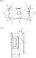
- Fig. 1 shows a schematic diagram of a motor vehicle 1 according to the invention, with which a detection of the surroundings by radar sensors 2 of a radar system is possible in a 360 ° angular range around the motor vehicle 1, as visualized by the indicated detection areas 3.
- the three front radar sensors 2 are installed in a front bumper 4, and the three rear radar sensors 2 are installed in a rear bumper 5.
- the lateral radar sensors 2 are provided in doors 6 of the motor vehicle 1, an overpainted radar-permeable window being provided in the door panel.
- the radar sensors 2 are implemented extremely compactly using CMOS technology.
- the radar system is also assigned a central control device 7, which in the present case also serves as a control device of a central driver assistance system in which the environment data of all environment sensors, including the radar sensors 2, are collected and summarized as an environment model, which is used to perform various functions Implement driver assistance systems.
- the radar system shown here with the radar sensors 2 and the control unit 7 is designed to carry out the method according to the invention.
- the radar sensors 2 are clearly all installed in a clearly defined manner at different installation positions in the motor vehicle. Their alignment and their installation environment are therefore, at least for the most part, already known when the motor vehicle 1 is designed. This is exploited in that installation-specific configuration information is stored in control device 7 for each installation position, the operating software and / or configuration parameters for radar sensors installed at the corresponding installation position 2 contains. This means that the radar sensors 2 are all designed the same at the time of installation, both in terms of hardware and software design. After the corresponding radar sensor 2 has been installed, it logs on to the control unit 7 via a corresponding communication connection, which then also knows the installation position of the radar sensor 2. Methods for determining the installation position or for identifying radar sensors 2 are already known and can also be used here, be it by using dedicated connections to each radar sensor 2 or by coding the installation position via radar sensor internal or external radar sensor devices, test measurements and the like.
- the control device 7 then transmits the configuration information assigned to the installation position back to the corresponding radar sensor 2, which uses it to configure itself accordingly, thus for example appropriately installing operating software and / or implementing the configuration parameters, which are operating parameters in particular.
- the configuration information includes operating parameters that describe the installation environment and adaptations of the measurement process. For example, components to be irradiated by the radar sensor and / or components which otherwise influence the measurement are taken into account in order to achieve optimal performance of the radar sensors 2 at the installation position.
- the operating parameters can, for example, transmit parameters, in particular the number of chirps and the frequency bandwidth, as well as evaluation parameters, in particular parameters of a fast Fourier transformation, tracking parameters that parameterize tracking algorithms or can be used to select tracking algorithms, misalignment parameters that relate to misalignment detection algorithms, threshold values for detection and the like include more.
- a calibration value of 0.5 °, a detection threshold of 0.5 °, a detection threshold of 2.5 decibels, multi-object tracking as a tracking hypothesis, a particle filter as a tracking algorithm, a Frequency bandwidth of 4 GHz etc. must be specified.
- a radar sensor 2 installed in a bumper 4, 5 with a bumper base part 8 and a bumper closing part 9, which in the present case has a printed circuit board 11 held in a housing 10 on which a package 12 composed of a CMOS chip 13 and an antenna arrangement 14 is arranged.
- the CMOS chip 13 also realizes a control unit and a digital signal processing component of the radar sensor 2.
- the detection area 3 of the radar sensor 2 has already been selected specifically for the installation position so that as few disruptive influences as possible from the bumper closing part 4 and other components, such as the metallic component 15, occur.
- the bumper closing part 9 must be irradiated as a component to be irradiated and therefore already has a certain weakening effect which can be taken into account accordingly in the transmission parameters and / or evaluation parameters.
- the bumper closing part 9 also has a discontinuity in the form of ribs, which can provide unwanted reflections. Such effects can also be taken into account if optimal operating parameters for the radar sensor 2 are determined. Reflection effects occurring in side lobes also appear the component 15 and the bumper closing part 9, as indicated according to the arrows 17, are taken into account.
- the operating parameters of the configuration information allow the radar sensor 2 to be operated in an ideally matched manner to its installation position and the installation environment given there.
Landscapes
- Engineering & Computer Science (AREA)
- Radar, Positioning & Navigation (AREA)
- Remote Sensing (AREA)
- Physics & Mathematics (AREA)
- Computer Networks & Wireless Communication (AREA)
- General Physics & Mathematics (AREA)
- Electromagnetism (AREA)
- Radar Systems Or Details Thereof (AREA)
Claims (6)
- Procédé pour mettre en service des capteurs radar (2) dans un véhicule à moteur (1), dans lequel les capteurs radar (2) sont montés à différentes positions de montage dans le véhicule à moteur (1) ;
caractérisé en ce qu'
après le montage d'un capteur radar (2) à une position de montage, un logiciel de mise en service et/ou des informations de configuration comprenant des paramètres de configuration d'un dispositif de commande (7) central communiquant avec les capteurs radar (2) est/sont transmis(es) au capteur radar (2) et y est/sont utilisé(es) pour la configuration du capteur radar (2), à la suite de quoi le capteur radar (2) est mis en service selon les informations de configuration, dans lequel les paramètres de fonctionnement décrivant les adaptations du processus de mesure concernant l'environnement de montage sont utilisés comme informations de configuration, dans lequel des paramètres de mise en service prenant en compte des caractéristiques d'un composant (15) à rayonner et/ou saisi par des lobes radar secondaires pendant le processus de mesure du véhicule à moteur (1) sont utilisés, dans lequel au moins un paramètre d'évaluation décrivant un seuil de détection et/ou au moins un paramètre de suivi concernant un suivi d'un objet et/ou au moins un paramètre de désajustement concernant un contrôle d'un désajustement et/ou au moins un paramètre d'évaluation concernant une transformation rapide de Fourier et/ou au moins un paramètre d'émission décrivant le nombre de fréquences parasites et/ou la bande de fréquence sont utilisés comme paramètre de mise de service. - Procédé selon la revendication 1, caractérisé en ce que
les capteurs radar (2) sont montés au moins partiellement derrière un composant à rayonner du véhicule à moteur (1), en particulier dans un pare-chocs (4, 5) ou dans une porte (6), et/ou les en particulier huit capteurs radar (2) font partie d'un système radar saisissant l'environnement du véhicule à moteur (1) dans une zone angulaire de 360°. - Procédé selon la revendication 1 ou 2,
caractérisé en ce que
les informations de configuration comprennent des données d'étalonnage, en particulier concernant la position de montage et/ou une transformation entre un système de coordonnées du capteur radar (2) et un système de coordonnées du véhicule à moteur (1). - Procédé selon l'une quelconque des revendications précédentes,
caractérisé en ce que
des paramètres de mise en service décrivant la zone de détection souhaitée (3) à la position de montage sont utilisés. - Procédé selon l'une quelconque des revendications précédentes,
caractérisé en ce que
des capteurs radar (2) sont utilisés, qui sont tous réalisés de manière identique avant la configuration. - Véhicule à moteur (1), comprenant un système radar avec plusieurs capteurs radar (2), qui sont montés à différentes positions de montage dans le véhicule à moteur (1), et un dispositif de commande (7), qui est réalisé pour effectuer un procédé selon l'une quelconque des revendications précédentes.
Applications Claiming Priority (1)
| Application Number | Priority Date | Filing Date | Title |
|---|---|---|---|
| DE102015011022.5A DE102015011022B4 (de) | 2015-08-22 | 2015-08-22 | Verfahren zum Betrieb von Radarsensoren in einem Kraftfahrzeug und Kraftfahrzeug |
Publications (2)
| Publication Number | Publication Date |
|---|---|
| EP3136124A1 EP3136124A1 (fr) | 2017-03-01 |
| EP3136124B1 true EP3136124B1 (fr) | 2020-09-09 |
Family
ID=56413589
Family Applications (1)
| Application Number | Title | Priority Date | Filing Date |
|---|---|---|---|
| EP16179733.7A Active EP3136124B1 (fr) | 2015-08-22 | 2016-07-15 | Procédé pour mettre en service des capteurs radar dans un véhicule à moteur et véhicule à moteur |
Country Status (2)
| Country | Link |
|---|---|
| EP (1) | EP3136124B1 (fr) |
| DE (1) | DE102015011022B4 (fr) |
Families Citing this family (1)
| Publication number | Priority date | Publication date | Assignee | Title |
|---|---|---|---|---|
| EP3483623A1 (fr) * | 2017-11-13 | 2019-05-15 | CUB Elecparts Inc. | Procédé de réglage de radar de véhicule |
Family Cites Families (4)
| Publication number | Priority date | Publication date | Assignee | Title |
|---|---|---|---|---|
| DE102004038494A1 (de) * | 2004-08-07 | 2006-03-16 | Robert Bosch Gmbh | Verfahren und Vorrichtung zum Betreiben eines Sensorsystems |
| DE102011086244A1 (de) * | 2011-11-14 | 2013-05-16 | Robert Bosch Gmbh | Verfahren zum Betreiben eines Sensors |
| DE102014009869A1 (de) * | 2014-07-03 | 2016-01-21 | Audi Ag | Verfahren zum Betrieb eines Radarsensors in einem Kraftfahrzeug und Kraftfahrzeug |
| DE102014017917B3 (de) * | 2014-12-04 | 2015-11-12 | Audi Ag | Verfahren zum Konfigurieren wenigstens eines an einer von mehreren Einbaupositionen in einem Kraftfahrzeug verbauten Radarsensors hinsichtlich der Einbauposition und Kraftfahrzeug |
-
2015
- 2015-08-22 DE DE102015011022.5A patent/DE102015011022B4/de active Active
-
2016
- 2016-07-15 EP EP16179733.7A patent/EP3136124B1/fr active Active
Non-Patent Citations (1)
| Title |
|---|
| None * |
Also Published As
| Publication number | Publication date |
|---|---|
| DE102015011022B4 (de) | 2019-11-28 |
| EP3136124A1 (fr) | 2017-03-01 |
| DE102015011022A1 (de) | 2017-02-23 |
Similar Documents
| Publication | Publication Date | Title |
|---|---|---|
| EP3452847B1 (fr) | Véhicule automobile comprenant au moins deux capteurs radars | |
| DE102017216435A1 (de) | Verfahren zum Betrieb von Radarsensoren und Kraftfahrzeug | |
| EP1274909A1 (fr) | Systeme pour controler l'autorisation d'acces a un vehicule | |
| EP3130940B1 (fr) | Procede d'amelioration de la performance d'un capteur radar base sur la technologie des semi-conducteurs dans un vehicule automobile et vehicule automobile | |
| EP3215866B1 (fr) | Capteur radar pour l'utilisation à une partie d'un véhicule, véhicule et procédé pour l'operation d'un capteur radar | |
| DE102015011020B3 (de) | Verfahren zur Zuordnung von vorgegebenen Einbaupositionen zu an den Einbaupositionen in einem Kraftfahrzeug verbauten Radarsensoren und Kraftfahrzeug | |
| EP3239733B1 (fr) | Procédé de fonctionnement d'un capteur radar dans un véhicule automobile et véhicule automobile | |
| DE102016220084A1 (de) | Kraftfahrzeug mit wenigstens einer Tür und einem Radarsensor, Verfahren zur Steuerung einer Antriebseinrichtung für eine Tür eines Kraftfahrzeugs | |
| DE102014010381A1 (de) | Verfahren zum Betrieb eines Fahrzeugsystems eines Kraftfahrzeugs zum Schutz vor Beschädigungen durch Unebenheiten des Untergrunds und Kraftfahrzeug | |
| DE102015007040B4 (de) | Verfahren zur Detektion und Klassifikation von Fußgängern in einer Umgebung eines Kraftfahrzeugs und Kraftfahrzeug | |
| DE102014011121A1 (de) | Kraftfahrzeug mit einem Kollisionsschutzsystem für wenigstens eine Tür | |
| DE102016001310B4 (de) | Verfahren zum Betrieb eines verdeckt verbauten Radarsensors in einem Kraftfahrzeug, Radarsensoranordnung und Kraftfahrzeug | |
| DE102016004305A1 (de) | Kraftfahrzeug mit mehreren an unterschiedlichen Einbaupositionen angeordneten Radarsensoren und Verfahren zum Betreiben mehrerer an unterschiedlichen Einbaupositionen eines Kraftfahrzeugs angeordneter Radarsensoren | |
| DE102015011928A1 (de) | Verfahren zum Betrieb eines Sicherheitssystems eines Kraftfahrzeugs und Kraftfahrzeug | |
| DE102015007034B4 (de) | Verfahren zum Betrieb eines Parkassistenzsystems eines Kraftfahrzeugs und Kraftfahrzeug | |
| DE102014111098A1 (de) | Sensorvorrichtung mit Ultraschallsensor und Radarsensor zum Erfassen eines Objekts in einem Umfeld eines Kraftfahrzeugs und Kraftfahrzeug | |
| EP3136124B1 (fr) | Procédé pour mettre en service des capteurs radar dans un véhicule à moteur et véhicule à moteur | |
| DE102017216567A1 (de) | Verfahrung zur Ermittlung einer Umgebungskarte in einem Kraftfahrzeug und Kraftfahrzeug | |
| DE102019211722B3 (de) | Kraftfahrzeug und Verfahren zum Betrieb von Radarsensoren in einem Kraftfahrzeug | |
| DE102015004468A1 (de) | Verfahren zum Betrieb eines Fahrerassistenzsystems und Kraftfahrzeug | |
| EP3109663B1 (fr) | Procédé destiné au fonctionnement d'un système d'assistance du conducteur d'un véhicule automobile et véhicule automobile | |
| DE102017214964B4 (de) | Verfahren zur Ermittlung einer Umfeldkarte in einem Kraftfahrzeug und Kraftfahrzeug | |
| DE102019114876B4 (de) | Radarantennenanordnung für ein Fahrzeug, umfassend zumindest ein Fahrzeugbauteil, und Fahrzeug | |
| EP3059606A1 (fr) | Procede de determination d'une information de densite de trafic dans un vehicule automobile et vehicule automobile | |
| DE102015009308B4 (de) | Verfahren zum Betrieb eines Fahrerassistenzsystems und Kraftfahrzeug |
Legal Events
| Date | Code | Title | Description |
|---|---|---|---|
| PUAI | Public reference made under article 153(3) epc to a published international application that has entered the european phase |
Free format text: ORIGINAL CODE: 0009012 |
|
| STAA | Information on the status of an ep patent application or granted ep patent |
Free format text: STATUS: THE APPLICATION HAS BEEN PUBLISHED |
|
| AK | Designated contracting states |
Kind code of ref document: A1 Designated state(s): AL AT BE BG CH CY CZ DE DK EE ES FI FR GB GR HR HU IE IS IT LI LT LU LV MC MK MT NL NO PL PT RO RS SE SI SK SM TR |
|
| AX | Request for extension of the european patent |
Extension state: BA ME |
|
| STAA | Information on the status of an ep patent application or granted ep patent |
Free format text: STATUS: REQUEST FOR EXAMINATION WAS MADE |
|
| 17P | Request for examination filed |
Effective date: 20170901 |
|
| RBV | Designated contracting states (corrected) |
Designated state(s): AL AT BE BG CH CY CZ DE DK EE ES FI FR GB GR HR HU IE IS IT LI LT LU LV MC MK MT NL NO PL PT RO RS SE SI SK SM TR |
|
| STAA | Information on the status of an ep patent application or granted ep patent |
Free format text: STATUS: EXAMINATION IS IN PROGRESS |
|
| 17Q | First examination report despatched |
Effective date: 20190508 |
|
| RIC1 | Information provided on ipc code assigned before grant |
Ipc: G01S 13/87 20060101ALI20200325BHEP Ipc: G01S 13/931 20200101ALI20200325BHEP Ipc: G01S 13/02 20060101ALN20200325BHEP Ipc: G01S 7/40 20060101AFI20200325BHEP |
|
| GRAP | Despatch of communication of intention to grant a patent |
Free format text: ORIGINAL CODE: EPIDOSNIGR1 |
|
| STAA | Information on the status of an ep patent application or granted ep patent |
Free format text: STATUS: GRANT OF PATENT IS INTENDED |
|
| INTG | Intention to grant announced |
Effective date: 20200526 |
|
| RIN1 | Information on inventor provided before grant (corrected) |
Inventor name: KHLIFI, RACHID |
|
| GRAS | Grant fee paid |
Free format text: ORIGINAL CODE: EPIDOSNIGR3 |
|
| GRAA | (expected) grant |
Free format text: ORIGINAL CODE: 0009210 |
|
| STAA | Information on the status of an ep patent application or granted ep patent |
Free format text: STATUS: THE PATENT HAS BEEN GRANTED |
|
| AK | Designated contracting states |
Kind code of ref document: B1 Designated state(s): AL AT BE BG CH CY CZ DE DK EE ES FI FR GB GR HR HU IE IS IT LI LT LU LV MC MK MT NL NO PL PT RO RS SE SI SK SM TR |
|
| REG | Reference to a national code |
Ref country code: GB Ref legal event code: FG4D Free format text: NOT ENGLISH |
|
| REG | Reference to a national code |
Ref country code: AT Ref legal event code: REF Ref document number: 1312268 Country of ref document: AT Kind code of ref document: T Effective date: 20200915 Ref country code: CH Ref legal event code: EP |
|
| REG | Reference to a national code |
Ref country code: DE Ref legal event code: R096 Ref document number: 502016011085 Country of ref document: DE |
|
| REG | Reference to a national code |
Ref country code: IE Ref legal event code: FG4D Free format text: LANGUAGE OF EP DOCUMENT: GERMAN |
|
| REG | Reference to a national code |
Ref country code: LT Ref legal event code: MG4D |
|
| PG25 | Lapsed in a contracting state [announced via postgrant information from national office to epo] |
Ref country code: NO Free format text: LAPSE BECAUSE OF FAILURE TO SUBMIT A TRANSLATION OF THE DESCRIPTION OR TO PAY THE FEE WITHIN THE PRESCRIBED TIME-LIMIT Effective date: 20201209 Ref country code: SE Free format text: LAPSE BECAUSE OF FAILURE TO SUBMIT A TRANSLATION OF THE DESCRIPTION OR TO PAY THE FEE WITHIN THE PRESCRIBED TIME-LIMIT Effective date: 20200909 Ref country code: FI Free format text: LAPSE BECAUSE OF FAILURE TO SUBMIT A TRANSLATION OF THE DESCRIPTION OR TO PAY THE FEE WITHIN THE PRESCRIBED TIME-LIMIT Effective date: 20200909 Ref country code: LT Free format text: LAPSE BECAUSE OF FAILURE TO SUBMIT A TRANSLATION OF THE DESCRIPTION OR TO PAY THE FEE WITHIN THE PRESCRIBED TIME-LIMIT Effective date: 20200909 Ref country code: HR Free format text: LAPSE BECAUSE OF FAILURE TO SUBMIT A TRANSLATION OF THE DESCRIPTION OR TO PAY THE FEE WITHIN THE PRESCRIBED TIME-LIMIT Effective date: 20200909 Ref country code: BG Free format text: LAPSE BECAUSE OF FAILURE TO SUBMIT A TRANSLATION OF THE DESCRIPTION OR TO PAY THE FEE WITHIN THE PRESCRIBED TIME-LIMIT Effective date: 20201209 Ref country code: GR Free format text: LAPSE BECAUSE OF FAILURE TO SUBMIT A TRANSLATION OF THE DESCRIPTION OR TO PAY THE FEE WITHIN THE PRESCRIBED TIME-LIMIT Effective date: 20201210 |
|
| REG | Reference to a national code |
Ref country code: NL Ref legal event code: MP Effective date: 20200909 |
|
| PG25 | Lapsed in a contracting state [announced via postgrant information from national office to epo] |
Ref country code: RS Free format text: LAPSE BECAUSE OF FAILURE TO SUBMIT A TRANSLATION OF THE DESCRIPTION OR TO PAY THE FEE WITHIN THE PRESCRIBED TIME-LIMIT Effective date: 20200909 Ref country code: PL Free format text: LAPSE BECAUSE OF FAILURE TO SUBMIT A TRANSLATION OF THE DESCRIPTION OR TO PAY THE FEE WITHIN THE PRESCRIBED TIME-LIMIT Effective date: 20200909 Ref country code: LV Free format text: LAPSE BECAUSE OF FAILURE TO SUBMIT A TRANSLATION OF THE DESCRIPTION OR TO PAY THE FEE WITHIN THE PRESCRIBED TIME-LIMIT Effective date: 20200909 |
|
| PG25 | Lapsed in a contracting state [announced via postgrant information from national office to epo] |
Ref country code: NL Free format text: LAPSE BECAUSE OF FAILURE TO SUBMIT A TRANSLATION OF THE DESCRIPTION OR TO PAY THE FEE WITHIN THE PRESCRIBED TIME-LIMIT Effective date: 20200909 Ref country code: CZ Free format text: LAPSE BECAUSE OF FAILURE TO SUBMIT A TRANSLATION OF THE DESCRIPTION OR TO PAY THE FEE WITHIN THE PRESCRIBED TIME-LIMIT Effective date: 20200909 Ref country code: PT Free format text: LAPSE BECAUSE OF FAILURE TO SUBMIT A TRANSLATION OF THE DESCRIPTION OR TO PAY THE FEE WITHIN THE PRESCRIBED TIME-LIMIT Effective date: 20210111 Ref country code: SM Free format text: LAPSE BECAUSE OF FAILURE TO SUBMIT A TRANSLATION OF THE DESCRIPTION OR TO PAY THE FEE WITHIN THE PRESCRIBED TIME-LIMIT Effective date: 20200909 Ref country code: RO Free format text: LAPSE BECAUSE OF FAILURE TO SUBMIT A TRANSLATION OF THE DESCRIPTION OR TO PAY THE FEE WITHIN THE PRESCRIBED TIME-LIMIT Effective date: 20200909 Ref country code: EE Free format text: LAPSE BECAUSE OF FAILURE TO SUBMIT A TRANSLATION OF THE DESCRIPTION OR TO PAY THE FEE WITHIN THE PRESCRIBED TIME-LIMIT Effective date: 20200909 |
|
| PG25 | Lapsed in a contracting state [announced via postgrant information from national office to epo] |
Ref country code: AL Free format text: LAPSE BECAUSE OF FAILURE TO SUBMIT A TRANSLATION OF THE DESCRIPTION OR TO PAY THE FEE WITHIN THE PRESCRIBED TIME-LIMIT Effective date: 20200909 Ref country code: ES Free format text: LAPSE BECAUSE OF FAILURE TO SUBMIT A TRANSLATION OF THE DESCRIPTION OR TO PAY THE FEE WITHIN THE PRESCRIBED TIME-LIMIT Effective date: 20200909 Ref country code: IS Free format text: LAPSE BECAUSE OF FAILURE TO SUBMIT A TRANSLATION OF THE DESCRIPTION OR TO PAY THE FEE WITHIN THE PRESCRIBED TIME-LIMIT Effective date: 20210109 |
|
| REG | Reference to a national code |
Ref country code: DE Ref legal event code: R097 Ref document number: 502016011085 Country of ref document: DE |
|
| PG25 | Lapsed in a contracting state [announced via postgrant information from national office to epo] |
Ref country code: SK Free format text: LAPSE BECAUSE OF FAILURE TO SUBMIT A TRANSLATION OF THE DESCRIPTION OR TO PAY THE FEE WITHIN THE PRESCRIBED TIME-LIMIT Effective date: 20200909 |
|
| PLBE | No opposition filed within time limit |
Free format text: ORIGINAL CODE: 0009261 |
|
| STAA | Information on the status of an ep patent application or granted ep patent |
Free format text: STATUS: NO OPPOSITION FILED WITHIN TIME LIMIT |
|
| 26N | No opposition filed |
Effective date: 20210610 |
|
| PG25 | Lapsed in a contracting state [announced via postgrant information from national office to epo] |
Ref country code: DK Free format text: LAPSE BECAUSE OF FAILURE TO SUBMIT A TRANSLATION OF THE DESCRIPTION OR TO PAY THE FEE WITHIN THE PRESCRIBED TIME-LIMIT Effective date: 20200909 Ref country code: SI Free format text: LAPSE BECAUSE OF FAILURE TO SUBMIT A TRANSLATION OF THE DESCRIPTION OR TO PAY THE FEE WITHIN THE PRESCRIBED TIME-LIMIT Effective date: 20200909 |
|
| PG25 | Lapsed in a contracting state [announced via postgrant information from national office to epo] |
Ref country code: IT Free format text: LAPSE BECAUSE OF FAILURE TO SUBMIT A TRANSLATION OF THE DESCRIPTION OR TO PAY THE FEE WITHIN THE PRESCRIBED TIME-LIMIT Effective date: 20200909 |
|
| REG | Reference to a national code |
Ref country code: CH Ref legal event code: PL |
|
| PG25 | Lapsed in a contracting state [announced via postgrant information from national office to epo] |
Ref country code: MC Free format text: LAPSE BECAUSE OF FAILURE TO SUBMIT A TRANSLATION OF THE DESCRIPTION OR TO PAY THE FEE WITHIN THE PRESCRIBED TIME-LIMIT Effective date: 20200909 |
|
| REG | Reference to a national code |
Ref country code: BE Ref legal event code: MM Effective date: 20210731 |
|
| PG25 | Lapsed in a contracting state [announced via postgrant information from national office to epo] |
Ref country code: LI Free format text: LAPSE BECAUSE OF NON-PAYMENT OF DUE FEES Effective date: 20210731 Ref country code: CH Free format text: LAPSE BECAUSE OF NON-PAYMENT OF DUE FEES Effective date: 20210731 |
|
| PG25 | Lapsed in a contracting state [announced via postgrant information from national office to epo] |
Ref country code: LU Free format text: LAPSE BECAUSE OF NON-PAYMENT OF DUE FEES Effective date: 20210715 |
|
| PG25 | Lapsed in a contracting state [announced via postgrant information from national office to epo] |
Ref country code: IE Free format text: LAPSE BECAUSE OF NON-PAYMENT OF DUE FEES Effective date: 20210715 Ref country code: BE Free format text: LAPSE BECAUSE OF NON-PAYMENT OF DUE FEES Effective date: 20210731 |
|
| REG | Reference to a national code |
Ref country code: AT Ref legal event code: MM01 Ref document number: 1312268 Country of ref document: AT Kind code of ref document: T Effective date: 20210715 |
|
| PG25 | Lapsed in a contracting state [announced via postgrant information from national office to epo] |
Ref country code: AT Free format text: LAPSE BECAUSE OF NON-PAYMENT OF DUE FEES Effective date: 20210715 |
|
| PG25 | Lapsed in a contracting state [announced via postgrant information from national office to epo] |
Ref country code: HU Free format text: LAPSE BECAUSE OF FAILURE TO SUBMIT A TRANSLATION OF THE DESCRIPTION OR TO PAY THE FEE WITHIN THE PRESCRIBED TIME-LIMIT; INVALID AB INITIO Effective date: 20160715 |
|
| PG25 | Lapsed in a contracting state [announced via postgrant information from national office to epo] |
Ref country code: CY Free format text: LAPSE BECAUSE OF FAILURE TO SUBMIT A TRANSLATION OF THE DESCRIPTION OR TO PAY THE FEE WITHIN THE PRESCRIBED TIME-LIMIT Effective date: 20200909 |
|
| P01 | Opt-out of the competence of the unified patent court (upc) registered |
Effective date: 20230530 |
|
| PGFP | Annual fee paid to national office [announced via postgrant information from national office to epo] |
Ref country code: GB Payment date: 20230720 Year of fee payment: 8 |
|
| PGFP | Annual fee paid to national office [announced via postgrant information from national office to epo] |
Ref country code: FR Payment date: 20230721 Year of fee payment: 8 Ref country code: DE Payment date: 20230731 Year of fee payment: 8 |
|
| PG25 | Lapsed in a contracting state [announced via postgrant information from national office to epo] |
Ref country code: MK Free format text: LAPSE BECAUSE OF FAILURE TO SUBMIT A TRANSLATION OF THE DESCRIPTION OR TO PAY THE FEE WITHIN THE PRESCRIBED TIME-LIMIT Effective date: 20200909 |