EP3136082A1 - Cyclic flexing salt-spray chamber and methods - Google Patents
Cyclic flexing salt-spray chamber and methods Download PDFInfo
- Publication number
- EP3136082A1 EP3136082A1 EP16183323.1A EP16183323A EP3136082A1 EP 3136082 A1 EP3136082 A1 EP 3136082A1 EP 16183323 A EP16183323 A EP 16183323A EP 3136082 A1 EP3136082 A1 EP 3136082A1
- Authority
- EP
- European Patent Office
- Prior art keywords
- material system
- flexing
- chamber
- salt fog
- exposing
- Prior art date
- Legal status (The legal status is an assumption and is not a legal conclusion. Google has not performed a legal analysis and makes no representation as to the accuracy of the status listed.)
- Granted
Links
Images

Classifications
-
- G—PHYSICS
- G01—MEASURING; TESTING
- G01N—INVESTIGATING OR ANALYSING MATERIALS BY DETERMINING THEIR CHEMICAL OR PHYSICAL PROPERTIES
- G01N17/00—Investigating resistance of materials to the weather, to corrosion, or to light
- G01N17/02—Electrochemical measuring systems for weathering, corrosion or corrosion-protection measurement
-
- G—PHYSICS
- G01—MEASURING; TESTING
- G01N—INVESTIGATING OR ANALYSING MATERIALS BY DETERMINING THEIR CHEMICAL OR PHYSICAL PROPERTIES
- G01N17/00—Investigating resistance of materials to the weather, to corrosion, or to light
-
- G—PHYSICS
- G01—MEASURING; TESTING
- G01N—INVESTIGATING OR ANALYSING MATERIALS BY DETERMINING THEIR CHEMICAL OR PHYSICAL PROPERTIES
- G01N17/00—Investigating resistance of materials to the weather, to corrosion, or to light
- G01N17/002—Test chambers
-
- G—PHYSICS
- G01—MEASURING; TESTING
- G01N—INVESTIGATING OR ANALYSING MATERIALS BY DETERMINING THEIR CHEMICAL OR PHYSICAL PROPERTIES
- G01N3/00—Investigating strength properties of solid materials by application of mechanical stress
- G01N3/32—Investigating strength properties of solid materials by application of mechanical stress by applying repeated or pulsating forces
-
- G—PHYSICS
- G01—MEASURING; TESTING
- G01N—INVESTIGATING OR ANALYSING MATERIALS BY DETERMINING THEIR CHEMICAL OR PHYSICAL PROPERTIES
- G01N17/00—Investigating resistance of materials to the weather, to corrosion, or to light
- G01N17/006—Investigating resistance of materials to the weather, to corrosion, or to light of metals
-
- G—PHYSICS
- G01—MEASURING; TESTING
- G01N—INVESTIGATING OR ANALYSING MATERIALS BY DETERMINING THEIR CHEMICAL OR PHYSICAL PROPERTIES
- G01N2203/00—Investigating strength properties of solid materials by application of mechanical stress
- G01N2203/0001—Type of application of the stress
- G01N2203/0005—Repeated or cyclic
- G01N2203/0007—Low frequencies up to 100 Hz
-
- G—PHYSICS
- G01—MEASURING; TESTING
- G01N—INVESTIGATING OR ANALYSING MATERIALS BY DETERMINING THEIR CHEMICAL OR PHYSICAL PROPERTIES
- G01N2203/00—Investigating strength properties of solid materials by application of mechanical stress
- G01N2203/0014—Type of force applied
- G01N2203/0023—Bending
-
- G—PHYSICS
- G01—MEASURING; TESTING
- G01N—INVESTIGATING OR ANALYSING MATERIALS BY DETERMINING THEIR CHEMICAL OR PHYSICAL PROPERTIES
- G01N2203/00—Investigating strength properties of solid materials by application of mechanical stress
- G01N2203/02—Details not specific for a particular testing method
- G01N2203/022—Environment of the test
- G01N2203/0236—Other environments
- G01N2203/024—Corrosive
Definitions
- aspects described herein generally relate to apparatus and methods for determining operational performance of material systems.
- an aircraft will experience repeated and harsh conditions resulting in degradation of component parts of the aircraft. Such degradation may take the form of, for example, corrosion and subsequent metal fatigue and fracture. Corrosion can contribute to a decrease in the integrity and strength of aircraft components. More specifically, a material system comprising aircraft components, such as fuselage or skin panels, a coated lap joint between two metal panels, or a wing-to-fuselage assembly on the exterior of an aircraft, may corrode over time due to exposure to mechanical and chemical stresses during use of the aircraft. Before a material is determined to be suitable for use as an aircraft material system, it may be desirable to determine the material system's propensity to corrode.
- aircraft components such as fuselage or skin panels, a coated lap joint between two metal panels, or a wing-to-fuselage assembly on the exterior of an aircraft.
- aspects described herein generally relate to methods and apparatus for determining operational environment-specific performance, lifetime assessment, and failure mode investigation of material systems.
- a method for determining material performance includes exposing a material system to salt fog. The method further includes flexing the material system.
- a method for determining material performance includes exposing a material system to a salt fog wherein the pH of the salt fog ranges from about 3.0 to about 9.0. The method further includes flexing the material system at a frequency from about 0.1 Hz to about 60 Hz.
- a material performance chamber comprises a salt fog chamber and a jaw configured to flex a material system.
- Apparatus generally comprise a salt fog chamber comprising material system flexing components to more accurately test corrosion of an aircraft material system such as a panel, a coated lap joint between two metal panels, and a wing-to-fuselage assembly.
- a corrosion chamber comprises an enclosure, a fog nozzle, a liquid reservoir, and a fixture support for gripping and flexing a material system.
- Methods for determining corrosion include exposing a material system to salt fog and flexing the material system at a frequency.
- a method for determining corrosion includes exposing a material system to a salt fog for a duration of about 1 hour to about 4500 hours wherein the pH of the salt fog is from about 3.0 to about 9.0 and flexing the panel at a frequency from about 0.1 Hz to about 60 Hz.
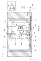
- Figure 1 is a plan view of an apparatus 100 for accelerating and controlling the corrosion-related failure modes of a material system, according to an aspect of the disclosure.
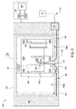
- Figure 2 is a side perspective view of apparatus 100 of Figure 1 .
- One or more components of apparatus 100 are made from materials that show resistance to a corrosive environment, such as an environment containing a salt fog.
- apparatus 100 includes an enclosure 160 having one or more fog nozzles 102 (one shown) disposed therein and configured to spray a treating liquid, such as a salt fog, in the enclosure 160.
- a fixture support is disposed in the enclosure to support a material system for exposure and flexing therein.
- Apparatus 100 includes a liquid reservoir 104 to supply a treating liquid to fog nozzle 102.
- Fog nozzle 102 may be a nozzle, such as an atomizing nozzle, a nozzle calibrated for air consumption, BETE full cone nozzle, hollow cone nozzle, fan misting nozzle, tank washing spray nozzle, NASA Mod1 nozzle for water spray atomization and droplet control, Q-Lab OEM fogging nozzle, Cool Clean ChilAire Lite spray applicator nozzle, and combinations thereof.
- Fog nozzle 102 may be comprised of materials such as hard rubber, plastic, or other inert materials.
- the fixture support comprises jaws 124a-e configured to flex a material system.
- Plate 146 is configured to support jaws 124a-e.
- plate 146 comprises a mounting plate disposed on an I-Beam grate.
- Plate 146 is positioned between fog nozzle 102 and jaws 124a-124e (as shown in Figures 1 and 2 ), allowing treating liquid to enter the enclosure without directly impinging upon a material system held by one or more jaws 124a-e. This configuration mimics general humid atmospheric conditions, as compared to direct rainfall onto an aircraft material system.
- jaws 124a-e may be positioned between fog nozzle 102 and plate 146 (this configuration not shown), allowing direct flow of treating liquid toward a material system held by one or more jaws 124a-e.
- This configuration mimics direct rain fall or aerosol deposition onto an aircraft material system.
- Fog nozzle 102 may be configured for flow angle adjustment, allowing flow of treating liquid at one or more angles relative to a material system surface.
- a material system surface may be parallel to a principal direction of flow of liquid through apparatus 100, based upon the dominant surface being tested, which reduces liquid collection on a material system during corrosion testing performed in apparatus 100.
- fog nozzle 102 may be directed or baffled so that the liquid does not impinge directly on a material system.
- a fog pump 108 is configured to assist flow of a liquid from liquid reservoir 104 to fog nozzle 102 via first fluid line 106 and second fluid line 110.
- First fluid line 106 couples liquid reservoir 104 at a first end with fog pump 108 at a second end to provide liquid communication of liquid reservoir 104 with fog pump 108.
- Second fluid line 110 couples fog pump 108 at a first end with fog nozzle 102 at a second end to provide liquid communication of fog pump 108 with fog nozzle 102.
- a compressed air source 112 and bubble tower 114 are configured to provide humidified air to fog nozzle 102.
- a pressure in the enclosure may be regulated to mimic the pressure experienced by an aircraft at various altitudes during real world use.
- compressed air source 112 is configured to flow air at a pressure ranging from about 2 PSI to about 50 PSI, from about 5 PSI to about 30 PSI, from about 12 PSI to about 18 PSI. In these ranges, lower pressure values mimic pressures experienced by an aircraft at higher altitudes while higher pressure values mimic pressures experienced by an aircraft at lower altitudes and closer to sea level.
- Air may include a mixture of gases similar to that found in an ambient atmosphere, for example, comprising about 78% N 2 , about 21% O 2 , and about 0.039% CO 2 , among other gases.
- Third fluid line 116 couples bubble tower 114 at a first end with fog nozzle 102 at a second end to provide air and liquid communication of bubble tower 114 with fog nozzle 102.
- a compressed air line 118 couples compressed air source 112 at a first end with bubble tower 114 at a second end to provide air communication of compressed air source 112 with bubble tower 114.
- Bubble tower 114 may contain a liquid, such as water, to provide initial humidification or additional humidification to air flowed from compressed air source 112 via compressed air line 118.
- a vent 122 may be coupled with the first chamber wall 130, a second chamber wall 132, or a third wall 152 ( Figure 2 ) to provide pressure regulation inside of apparatus 100.
- a heater 120 may be provided and configured to heat the inside of apparatus 100 such as enclosure 160. Heater 120 may be disposed adjacent to a first wall 130 of apparatus 100 and coupled with third wall 152 ( Figure 2 ). Heater 120 may be adhered to third wall 152 using by any suitable adherent, such as rivets. Heater 120 may be coupled with and controlled by controller 138.
- Fixture support is configured to support and flex a material system positioned in the enclosure for testing.
- Jaws 124a, 124b, 124c, 124d, and 124e are configured to flex a material system, such as a panel, a coated lap joint between two metal panels, a wing-to-fuselage assembly, and combinations thereof.
- the material system may be an aircraft material system, such as a panel, such as a skin or fuselage flat panel.
- the material system may have a width that is, for example, about 4 inches, and a length that is for example, about 6 inches to about 14.5 inches.
- the fixture support may flex a material system to a strain ranging from about 0.05% to about 50%, about 0.1 % to about 30%, about 0.3% to about 5%, such as about 0.37%.
- Fixture support comprising one or more jaws 124a-e is configured to grip and release a material system.
- Jaws 124a-e are configured to flex a material system from a first starting position to a fully or partially flexed second position.
- Jaws 124a-e are configured to flex a material system from a first position to greater than 0° to about 180° from the starting position, such as about 5° to about 90°, such as about 5° to about 45°, during a flexing process.
- Jaws 124a-124e may be the same size or different sizes.
- jaw 124a may be the same size as jaw 124b, but be a different size than jaw 124d (as shown in Figure 1 ).
- jaws 124a-124e may be positioned from one another by a distance that is the same or different than a distance between a different pair of jaws 124a-e. For example, a first distance between jaw 124a and 124b may be different than a second distance between jaw 124d and 124e.
- Various jaw sizes and various distances between jaws allow, for example, simultaneous testing of different sized material systems, such as panels, during an exposing and flexing process within apparatus 100.
- one or more of jaws 124a-e comprises steel.
- one or more of jaws 124a-e is anodized.
- one or more of jaws 124a-e comprises an inert material such as hard rubber and/or plastic.
- jaws 124a-e are configured to support a material system, such as a panel, from about 15° and about 30° relative to a first wall 130 and/or second wall 132, which reduces liquid collection on a material system during corrosion testing performed in apparatus 100.
- jaw 124a is configured to grip a material system at a first end of the material system and jaw 124b is configured to grip the material system at a second end of the material system.
- jaws 124a-e are configured to flex a material system simultaneously or alternatively.
- a motor 126 operates jaws 124a-e.
- Inlet tube 128 is coupled with motor 126 at a first end and coupled with first wall 130 at a second end for providing cooling material, such as air, to motor 126.
- Outlet tube 134 is coupled with motor 126 at a first end and coupled with first wall 130 at a second end for removing hot air exhaust from motor 126.
- Outer enclosure 136 surrounds motor 126 to enclose and protect the motor from liquid emitted from fog nozzle 102 or any other liquid present inside of apparatus 100.
- Jaws 124a-e are supported by plate 146.
- Plate 146 is supported by legs 148a, 148b, 148c, 148d, 148e, and 148f.
- Legs 148a-f are coupled with plate 146 at a first end and a chamber wall, a rack 150a, or a rack 150b at a second end.
- Parts of apparatus 100 described herein may comprise materials that are suitably inert to conditions within apparatus 100 during a cyclic flexing fog spray process.
- Suitably inert materials may include plastic, glass, stone, metal, rubber, and/or epoxy.
- Apparatus 100 may be controlled by a processor based system controller such as controller 138.
- the controller 138 may be configured to control apparatus 100 parts and processing parameters associated with a cyclic flexing fog spray process.
- the controller 138 includes a programmable central processing unit (CPU) 140 that is operable with a memory 142 and a mass storage device, an input control unit, and a display unit (not shown), such as power supplies, clocks, cache, input/output (I/O) circuits, and the like, coupled to the various components of the apparatus 100 to facilitate control of a cyclic flexing fog spray process.
- Controller 138 may be in electronic communication with, for example, outlet tube 134, vent 122, heater 120, and/or jaws 124a-e.
- the CPU 140 may be one of any form of general purpose computer processor that can be used in an industrial setting, such as a programmable logic controller (PLC), for controlling various chambers and sub-processors.
- the memory 142 is coupled to the CPU 140 and the memory 142 is non-transitory and may be one or more of readily available memory such as random access memory (RAM), read only memory (ROM), floppy disk drive, hard disk, or any other form of digital storage, local or remote.
- Support circuits 144 are coupled to the CPU 140 for supporting the processor in a conventional manner. Information obtained from cyclic flexing fog spray processes with apparatus 100 may be stored in the memory 142, typically as a software routine.
- the software routine may also be stored and/or executed by a second CPU (not shown) that is remotely located from the hardware being controlled by the CPU 140.
- the memory 142 is in the form of computer-readable storage media that contains instructions, that when executed by the CPU 140, facilitates the operation of the apparatus 100.
- the instructions in the memory 142 are in the form of a program product such as a program that implements the method of the present disclosure.
- the program code may conform to any one of a number of different programming languages.
- the disclosure may be implemented as a program product stored on computer-readable storage media for use with a computer system.
- the program(s) of the program product define functions of the aspects (including the methods described herein).
- Illustrative computer-readable storage media include, but are not limited to: (i) non-writable storage media (e.g., read-only memory devices within a computer such as CD-ROM disks readable by a CD-ROM drive, flash memory, ROM chips or any type of solid-state non-volatile semiconductor memory) on which information is permanently stored; and (ii) writable storage media (e.g., floppy disks within a diskette drive or hard-disk drive or any type of solid-state random-access semiconductor memory) on which alterable information is stored.
- non-writable storage media e.g., read-only memory devices within a computer such as CD-ROM disks readable by a CD-ROM drive, flash memory, ROM chips or any type of solid-state non-volatile semiconductor memory
- writable storage media e.g., floppy disks within a diskette drive or hard-disk drive or any type of solid-state random-access semiconductor memory
- FIG 3 is a plan view of an apparatus 300 for accelerating and controlling the corrosion-related failure modes of a material system, according to an aspect of the disclosure.
- the components of apparatus 300 are the same as the components shown in apparatus 100 of Figure 1 , except that motor 126 is not encompassed by outer enclosure 136 (outer enclosure 136 is not present), motor 126 is located external to first chamber wall 130, and inlet tube 128, and outlet tube 134 are not present.
- Motor 126 is coupled to first chamber wall 130.
- motor 126 (coupled to first chamber wall 130) translates bending motion inside the chamber via a screw, such as a ball screw, Acme screws, Lead screws, Roller screws, and screw mount, or an axle, passing into the chamber (not shown).
- a screw maintains spacing between stationary block 406 and mobile block 404 during flexing.
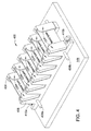
- FIG 4 is a perspective view of a flexer 400 configured to perform cyclic flexing, according to an aspect of the disclosure.
- Flexer 400 may be located inside of a material performance chamber, as described for Figure 1 .
- flexer 400 includes a mobile block 404 and a stationary block 406.
- Stationary block 406 is mounted to plate 146 by mounting bolts 410a and 410b.
- Mobile block 404 is slidably disposed on plate 146 adjacent to stationary block 406. Linear displacement between stationary block 406 and mobile block 404 is maintained by guide rods 408a and 408b.
- Guide rods 408a and 408b may comprise stainless steel, high density polypropylene, high density polyethylene, chromium, such as an Armology coating, and combinations thereof.
- Each of guide rods 408a and 408b is coupled with stationary block 406 and mobile block 404.
- Guide rods 408a and 408b are parallel to one another.
- Stationary block 406 and mobile block 404 mount or otherwise support jaws 124a-f.
- Stationary block 406 mounts a first side of jaws 124a-f in a stationary position during flexing, while mobile block 404 mounts a second side of jaws 124a-f and allows movement of the second side of jaws 124a-f during flexing.
- Stationary block 406 and mobile block 404 may comprise high density polyethylene.
- the mobile block is shifted laterally relative to the stationary block from a starting point to an end point resulting in flexing of the material system positioned in jaws 124a-f.
- the starting point , end point, and shift distance may be controlled by a user of flexer 400 based on test fixture mechanical boundary limits, mechanical stop blocks, or fixture driving system software controls.
- Each of stationary block 406 and mobile block 404 includes a base and a plurality of stanchions extending from the base perpendicular thereto. Each stanchion may be rectangular or angled to provide an angle on which each of the jaws 124a-f can be mounted. Jaws 124a-f are hinged, which allows bending of a material system while compressing the material system.
- jaws 124a-f may be mounted on one side of each stanchion and disposed at an angle from, for example, 15° to 30° relative to a line perpendicular to the base. Other angles relative to perpendicular are contemplated to achieve a desired testing condition for a material panel.
- the angle of jaws 124a-f determines the angular position of the material system.
- a material system is disposed at an angle from, for example, 15° to 30° relative to a line perpendicular to the base.
- jaws 124a-f are non-conductive and non-metallic so as to have little or no galvanic effect on the material system.
- One or more of jaws 124a-f may comprise high density polyethylene, commercial grade Titanium (II) with polyethylene insert, sacrificial 316SS with polyethylene insert, or combinations thereof, which prevents (partially or completely) galvanic corrosion of the jaws and material systems during testing.
- One or more of jaws 124a-f may comprise a sleeve cover comprising, for example, polyethylene, which further prevents galvanic corrosion of the jaws and material systems during testing.
- a material performance chamber contains more than one flexer 400. In some aspects where a material performance chamber contains more than one flexer 400, guide rods 408a and 408b extend through multiple flexers 400.
- a flexer such as flexer 400, provides variable displacement of a mobile block and material systems at variable frequencies that are adjustable in real-time.
- a flexer also allows for application of tension and compression to a material system.
- a material testing process such as a cyclic flexing fog spray process, for example, within apparatus 100, may be performed by exposing a material system, such as a panel, to a treating liquid, such as a salt fog, and flexing the material system.
- the exposing may be performed for from about 1 hour to about 4500 hours, such as about 200 hours to about 2000 hours, such as about 500 hours to about 1000 hours. Exposing a material system to a treating liquid for about 1 hour mimics, for example, salt fog exposure experienced by the material system as part of an aircraft in an arid climate.
- the liquid may contain water that is reagent grade water.
- the liquid may be a salt solution.
- the salt solution may comprise sodium chloride.
- the salt solution may contain about 2 parts sodium chloride in 98 parts water to about 6 parts sodium chloride in 94 parts water, such as about 5 parts sodium chloride in about 95 parts water.
- the liquid, such as a salt solution may contain less than about 0.1% of bromide, fluoride and iodide.
- the liquid such as a salt solution
- the liquid may contain less than about 1 ppm, such as about 0.3 ppm, by mass of copper.
- the liquid, such as a salt solution might not contain anti-caking agents, as such agents may act as corrosion inhibitors.
- Material systems which may be tested include, for example, aircraft panels which may form the skins or fuselage of an aircraft, a coated lap joint between two metal panels, a wing-to-fuselage assembly, and combinations thereof.
- the material systems may comprise a metal or alloy.
- Common material systems may comprise aluminum. Panels may comprise aluminum and/or an alloy, such as AA2024, AA7075, AA5083, aluminum lithium, or high entropy multicomponent alloys.
- the liquid may be atomized to form the treating liquid, such as a salt fog, that may have a pH ranging from about 3 to about 11, such as about 5 to about 8, such as about 6.5 to about 7.2. pH may be measured using a suitable glass pH-sensing electrode, reference electrode, and pH meter system. It may be desirable to adjust the pH of the treating liquid. For example, a treating liquid having a low pH may mimic a polluted atmosphere containing acid rain and the like. Furthermore, pH of the liquid that is atomized into the treating liquid may be adjusted to recalibrate the liquid during an exposing process. pH may be adjusted by, for example, addition of hydrochloric acid (HCl) to decrease the pH or addition of sodium hydroxide (NaOH) to increase the pH.
- HCl hydrochloric acid
- NaOH sodium hydroxide
- the liquid such as a salt fog
- the liquid may be flowed at a rate of about 0.5 milliliters per hour (mL/h) to about 5 mL/h per 80 cm 2 of horizontal collection area, such as about 1 mL/h to about 2 mL/h per 80 cm 2 of horizontal collection area.
- a material system such as a panel, may be flexed by a fixture support using one of jaws 124a-e or by a plurality of jaws 124a-e. Flexing may be performed at varying frequencies to mimic the effect of mechanical stresses for corrosive conditions experienced by an aircraft material system under real world conditions.
- a material system may be flexed at a frequency from about 0.1 Hertz (Hz) to about 150 Hz, about 0.1 Hz to about 100 Hz, about 0.1 Hz to about 60 Hz.
- Hz Hertz
- the greater the curvature of a flexed material system the greater the degradation to the material system using apparatus and methods of the present disclosure.
- a flat panel having a length of 6 inches may be gripped by two jaws with a distance of 6 inches between the two jaws.
- the panel may be flexed at a rate of 0.33 Hz during exposure to a salt fog solution.
- a flat panel having a length of 7.5 inches may be gripped by two jaws also having a distance of 6 inches between the two jaws.
- the panel may be flexed at a rate of 0.33 Hz during exposure to a salt fog solution.
- the panel having a length of 7.5 inches has an increased curvature and undergoes increased degradation as compared to the panel having a length of 6 inches under otherwise identical conditions.
- mechanical stresses that give curvature to a material system result in cracking of the material system which permits access of corrosive fluid, such as a salt fog, into a crack of the material system.
- corrosive fluid may further enter between various additional layers, if present, on the surface of the material system. Additional layers may include, for example, a surface finish, a primer, and/or a top coat. Accordingly, corrosive fluid may cause corrosion of the material system and/or one or more of the additional layers of the material system. Such conditions mimic the conditions experienced by an aircraft material system, such as a panel, during real world use.
- an exposure zone such as an enclosure 160 of apparatus 100
- the temperature may be monitored by a recording device or by a thermometer (not shown) that can be read from an outside surface of apparatus 100.
- exposing a material system, such as a panel, to a liquid, such as a salt fog, and flexing the material system may be performed concurrently. In some aspects, exposing a material system, such as a panel, to a liquid, such as a salt fog, and flexing the material system may be performed sequentially. In some aspects, a material system may be exposed to a salt fog and flexed concurrently as well as sequentially, which provides recreation of an irregular or variable flight-specific strain profile that may be experienced by a material system in service. In some aspects, exposing a material system to a liquid and/or flexing the material system may be interrupted to inspect, rearrange, or remove the material system, and/or replenish a solution, such as a solution in liquid reservoir 104.
- the material system is washed, such as with water, to remove byproducts of the treating solution, e.g., salt deposits, from the surface of the material system, followed by drying of the material system.
- a material system may, additionally or alternatively, be washed with an HCl solution and/or hexamethylene tetramine, followed by rinsing with reagent grade water. After washing, the material system may be dried.
- the extent of corrosion may be determined by a mass loss technique by weighing the material system after washing/drying and subtracting the weight from the weight of the material system before the exposing to a liquid, such as a salt fog, and the flexing.
- a material system such as a panel, may have one or more surface layers such as a surface finish, a primer, and/or a top coat. Corrosion may occur at one or more of these layers in a real world setting due to mechanical and chemical stresses. Apparatus and methods described herein allow for corrosion testing that mimics the corrosion experienced by a material system under real world conditions by subjecting the material system to mechanical as well as chemical stresses. Apparatus and methods described herein allow for corrosion testing at one or more of a material system surface, a finished surface, a primer surface, and/or a top coat surface.
- a material system is a flat metal panel, which may be coated.
- the material performance of the flat panel is tested by cyclically flexing the panel while exposing the panel to at least a cycle of salt fog. Following exposure and flexing, the panel is assessed for corrosion onset, rate of propagation, and performance.
- a material system comprises two flat metal panels connected, joined, or fastened together using metallic fasteners, screws, bolts, or other hardware, before being exposed to at least a cycle of salt fog. The material system may then be assessed for corrosion onset, rate of propagation, and performance.
- a material system comprises a mechanical joint or knuckle joint that may be made of metallic or composite materials and coated before being exposed to a cyclic salt fog before being assessed for corrosion onset, rate of propagation, and performance.
- a material system comprises a structural system replicative of aircraft components, representing a side-of-body join, a stringer-to-fuselage assembly, a fuselage panel, or wing spar-to-fuselage assembly.
- the produced assemblies may be actuated or flexed while being exposed to at least a cycles of salt fog before being assessed for corrosion onset, rate of propagation, and performance.
- Apparatus and methods described herein provide a controlled salt fog environment and monitoring of material performance, such as corrosion, on a variety of material systems, such as aircraft material systems, such as panels, coated lap joints between two or more panels, wing-to-fuselage assemblies, and combinations thereof. Apparatus and methods described herein provide an ability to replicate in-service, real-world failure modes and mechanisms in a controlled exposure environment.
- Mechanical flexing of a material system in an apparatus of the present disclosure may result in increased corrosion of a material system, such as a panel.
- the compounding effects of mechanical and chemical stresses combine to induce corrosion, which more accurately replicates corrosion experienced by a material system, such as an aircraft panel, in a real-world environment.
- the methods and apparatus of the present disclosure more accurately simulate the corrosion observed with aircraft material systems during real-world use of the aircraft.
- Methods and apparatus of the present disclosure allow for testing corrosion of stand-alone material systems and the interfaces between coating layers, which more accurately represents the corrosion experienced by material systems, such as panels, during actual use of the material systems as part of an aircraft.
- the methods and apparatus of the present disclosure further allow re-creation of irregular flight-specific strain profiles so that improved predictive as well as forensic investigations of aircraft material systems may be performed.
- aspects of the present disclosure may be devised without departing from the basic scope thereof.
- material systems such as aircraft material systems, such as panels, coated lap joints between two or more panels, and wing-to-fuselage assemblies
- aspects of the present disclosure may be directed to other material systems not associated with an aircraft, such as a multicomponent material system used in aerospace, automotive, marine, energy industry, and the like.
Landscapes
- Life Sciences & Earth Sciences (AREA)
- General Health & Medical Sciences (AREA)
- Immunology (AREA)
- Chemical & Material Sciences (AREA)
- Analytical Chemistry (AREA)
- Biochemistry (AREA)
- Physics & Mathematics (AREA)
- General Physics & Mathematics (AREA)
- Health & Medical Sciences (AREA)
- Pathology (AREA)
- Biodiversity & Conservation Biology (AREA)
- Ecology (AREA)
- Environmental & Geological Engineering (AREA)
- Environmental Sciences (AREA)
- Testing Resistance To Weather, Investigating Materials By Mechanical Methods (AREA)
Abstract
Description
- Aspects described herein generally relate to apparatus and methods for determining operational performance of material systems.
- Spanning the lifetime of operation, an aircraft will experience repeated and harsh conditions resulting in degradation of component parts of the aircraft. Such degradation may take the form of, for example, corrosion and subsequent metal fatigue and fracture. Corrosion can contribute to a decrease in the integrity and strength of aircraft components. More specifically, a material system comprising aircraft components, such as fuselage or skin panels, a coated lap joint between two metal panels, or a wing-to-fuselage assembly on the exterior of an aircraft, may corrode over time due to exposure to mechanical and chemical stresses during use of the aircraft. Before a material is determined to be suitable for use as an aircraft material system, it may be desirable to determine the material system's propensity to corrode. However, performance of aircraft material systems, such as panels, during actual, real world use of the aircraft seldom correlates with corrosion testing data. Furthermore, corrosion tests often lack consistency between tests. For example, variability is observed when similar material systems are corroded in different testing apparatuses even though the testing conditions are nominally similar. Material system corrosion during actual use versus corrosion experienced during testing is particularly disparate when the material system comprises alloys or the material system has surface finishes, primers or top coats applied to the material system. Furthermore, conventional processes for testing corrosion are not effective at controlling the environment at any particular site on or within a test material system.
- Therefore, there is a need in the art for methods and apparatus with controlled exposure environments for determining operational environment-specific performance, lifetime assessment, and failure mode investigation, i.e. an exposure environment that more closely mimics the conditions a material system will experience when incorporated as a component of an aircraft during actual, real-world use.
- Aspects described herein generally relate to methods and apparatus for determining operational environment-specific performance, lifetime assessment, and failure mode investigation of material systems.
- In one aspect, a method for determining material performance includes exposing a material system to salt fog. The method further includes flexing the material system.
- In another aspect, a method for determining material performance includes exposing a material system to a salt fog wherein the pH of the salt fog ranges from about 3.0 to about 9.0. The method further includes flexing the material system at a frequency from about 0.1 Hz to about 60 Hz.
- In another aspect, a material performance chamber comprises a salt fog chamber and a jaw configured to flex a material system.
- So that the manner in which the above recited features of the present disclosure can be understood in detail, a more particular description of the disclosure, briefly summarized above, may be had by reference to aspects, some of which are illustrated in the appended drawings. It is to be noted, however, that the appended drawings illustrate only typical aspects of this present disclosure and are therefore not to be considered limiting of its scope, for the present disclosure may admit to other equally effective aspects.
-
Figure 1 is a plan view of an apparatus for accelerating and controlling the corrosion-related failure modes of a material system, according to an aspect of the disclosure. -
Figure 2 is a side perspective view of an apparatus for accelerating and controlling the corrosion-related failure modes of a material system, according to an aspect of the disclosure. -
Figure 3 is a plan view of an apparatus for accelerating and controlling the corrosion-related failure modes of a material system, according to an aspect of the disclosure. -
Figure 4 is a perspective view of a flexer configured to perform cyclic flexing, according to an aspect of the disclosure. - To facilitate understanding, identical reference numerals have been used, where possible, to designate identical elements that are common to the figures. The figures are not drawn to scale and may be simplified for clarity. It is contemplated that elements and features of one aspect may be beneficially incorporated in other aspects without further recitation.
- The descriptions of the various aspects of the present disclosure have been presented for purposes of illustration, but are not intended to be exhaustive or limited to the aspects disclosed. Many modifications and variations will be apparent to those of ordinary skill in the art without departing from the scope and spirit of the described aspects. The terminology used herein was chosen to best explain the principles of the aspects, the practical application or technical improvement over technologies found in the marketplace, or to enable others of ordinary skill in the art to understand the aspects disclosed herein.
- Aspects described herein generally relate to apparatus and methods for determining operational performance of material systems. For example, determining operational environment-specific performance, lifetime assessment, and failure mode investigation of material systems may be accomplished by aspects described herein. Apparatus generally comprise a salt fog chamber comprising material system flexing components to more accurately test corrosion of an aircraft material system such as a panel, a coated lap joint between two metal panels, and a wing-to-fuselage assembly. In one aspect, a corrosion chamber comprises an enclosure, a fog nozzle, a liquid reservoir, and a fixture support for gripping and flexing a material system. Methods for determining corrosion include exposing a material system to salt fog and flexing the material system at a frequency. In one aspect, a method for determining corrosion includes exposing a material system to a salt fog for a duration of about 1 hour to about 4500 hours wherein the pH of the salt fog is from about 3.0 to about 9.0 and flexing the panel at a frequency from about 0.1 Hz to about 60 Hz.
-
Figure 1 is a plan view of anapparatus 100 for accelerating and controlling the corrosion-related failure modes of a material system, according to an aspect of the disclosure.Figure 2 is a side perspective view ofapparatus 100 ofFigure 1 . One or more components ofapparatus 100 are made from materials that show resistance to a corrosive environment, such as an environment containing a salt fog. As shown inFigures 1 and2 ,apparatus 100 includes anenclosure 160 having one or more fog nozzles 102 (one shown) disposed therein and configured to spray a treating liquid, such as a salt fog, in theenclosure 160. A fixture support is disposed in the enclosure to support a material system for exposure and flexing therein.Apparatus 100 includes aliquid reservoir 104 to supply a treating liquid to fognozzle 102. Fognozzle 102 may be a nozzle, such as an atomizing nozzle, a nozzle calibrated for air consumption, BETE full cone nozzle, hollow cone nozzle, fan misting nozzle, tank washing spray nozzle, NASA Mod1 nozzle for water spray atomization and droplet control, Q-Lab OEM fogging nozzle, Cool Clean ChilAire Lite spray applicator nozzle, and combinations thereof. Fognozzle 102 may be comprised of materials such as hard rubber, plastic, or other inert materials. - The fixture support comprises
jaws 124a-e configured to flex a material system.Plate 146 is configured to supportjaws 124a-e. In some aspects,plate 146 comprises a mounting plate disposed on an I-Beam grate.Plate 146 is positioned betweenfog nozzle 102 andjaws 124a-124e (as shown inFigures 1 and2 ), allowing treating liquid to enter the enclosure without directly impinging upon a material system held by one ormore jaws 124a-e. This configuration mimics general humid atmospheric conditions, as compared to direct rainfall onto an aircraft material system. Alternatively,jaws 124a-e may be positioned betweenfog nozzle 102 and plate 146 (this configuration not shown), allowing direct flow of treating liquid toward a material system held by one ormore jaws 124a-e. This configuration mimics direct rain fall or aerosol deposition onto an aircraft material system.Fog nozzle 102 may be configured for flow angle adjustment, allowing flow of treating liquid at one or more angles relative to a material system surface. In some aspects, a material system surface may be parallel to a principal direction of flow of liquid throughapparatus 100, based upon the dominant surface being tested, which reduces liquid collection on a material system during corrosion testing performed inapparatus 100. In such aspects,fog nozzle 102 may be directed or baffled so that the liquid does not impinge directly on a material system. (Fog nozzle 102, avent 122, amotor 126, anouter enclosure 136, andlegs 148a-f are shown as dashed lines inFigure 1 to indicate that these parts are located behind aplate 146 in the aspect shown inFigure 1 ). - A
fog pump 108 is configured to assist flow of a liquid fromliquid reservoir 104 to fognozzle 102 viafirst fluid line 106 andsecond fluid line 110.First fluid line 106 couplesliquid reservoir 104 at a first end withfog pump 108 at a second end to provide liquid communication ofliquid reservoir 104 withfog pump 108.Second fluid line 110couples fog pump 108 at a first end withfog nozzle 102 at a second end to provide liquid communication offog pump 108 withfog nozzle 102. - A
compressed air source 112 andbubble tower 114 are configured to provide humidified air to fognozzle 102. In some aspects, a pressure in the enclosure may be regulated to mimic the pressure experienced by an aircraft at various altitudes during real world use. Accordingly,compressed air source 112 is configured to flow air at a pressure ranging from about 2 PSI to about 50 PSI, from about 5 PSI to about 30 PSI, from about 12 PSI to about 18 PSI. In these ranges, lower pressure values mimic pressures experienced by an aircraft at higher altitudes while higher pressure values mimic pressures experienced by an aircraft at lower altitudes and closer to sea level. Air may include a mixture of gases similar to that found in an ambient atmosphere, for example, comprising about 78% N2, about 21% O2, and about 0.039% CO2, among other gases.Third fluid line 116couples bubble tower 114 at a first end withfog nozzle 102 at a second end to provide air and liquid communication ofbubble tower 114 withfog nozzle 102. Acompressed air line 118 couples compressedair source 112 at a first end withbubble tower 114 at a second end to provide air communication ofcompressed air source 112 withbubble tower 114.Bubble tower 114 may contain a liquid, such as water, to provide initial humidification or additional humidification to air flowed fromcompressed air source 112 viacompressed air line 118. - A
vent 122 may be coupled with thefirst chamber wall 130, asecond chamber wall 132, or a third wall 152 (Figure 2 ) to provide pressure regulation inside ofapparatus 100. Aheater 120 may be provided and configured to heat the inside ofapparatus 100 such asenclosure 160.Heater 120 may be disposed adjacent to afirst wall 130 ofapparatus 100 and coupled with third wall 152 (Figure 2 ).Heater 120 may be adhered tothird wall 152 using by any suitable adherent, such as rivets.Heater 120 may be coupled with and controlled bycontroller 138. - Fixture support is configured to support and flex a material system positioned in the enclosure for testing.
Jaws - Fixture support comprising one or
more jaws 124a-e is configured to grip and release a material system.Jaws 124a-e are configured to flex a material system from a first starting position to a fully or partially flexed second position.Jaws 124a-e are configured to flex a material system from a first position to greater than 0° to about 180° from the starting position, such as about 5° to about 90°, such as about 5° to about 45°, during a flexing process.Jaws 124a-124e may be the same size or different sizes. For example,jaw 124a may be the same size asjaw 124b, but be a different size thanjaw 124d (as shown inFigure 1 ). Furthermore,jaws 124a-124e may be positioned from one another by a distance that is the same or different than a distance between a different pair ofjaws 124a-e. For example, a first distance betweenjaw jaw apparatus 100. In some aspects, one or more ofjaws 124a-e comprises steel. In some aspects, one or more ofjaws 124a-e is anodized. In some aspects, one or more ofjaws 124a-e comprises an inert material such as hard rubber and/or plastic. In some aspects,jaws 124a-e are configured to support a material system, such as a panel, from about 15° and about 30° relative to afirst wall 130 and/orsecond wall 132, which reduces liquid collection on a material system during corrosion testing performed inapparatus 100. In some aspects,jaw 124a is configured to grip a material system at a first end of the material system andjaw 124b is configured to grip the material system at a second end of the material system. In some aspects,jaws 124a-e are configured to flex a material system simultaneously or alternatively. - A
motor 126 operatesjaws 124a-e.Inlet tube 128 is coupled withmotor 126 at a first end and coupled withfirst wall 130 at a second end for providing cooling material, such as air, tomotor 126.Outlet tube 134 is coupled withmotor 126 at a first end and coupled withfirst wall 130 at a second end for removing hot air exhaust frommotor 126.Outer enclosure 136 surroundsmotor 126 to enclose and protect the motor from liquid emitted fromfog nozzle 102 or any other liquid present inside ofapparatus 100.Jaws 124a-e are supported byplate 146.Plate 146 is supported bylegs Legs 148a-f are coupled withplate 146 at a first end and a chamber wall, arack 150a, or arack 150b at a second end. Parts ofapparatus 100 described herein may comprise materials that are suitably inert to conditions withinapparatus 100 during a cyclic flexing fog spray process. Suitably inert materials may include plastic, glass, stone, metal, rubber, and/or epoxy. -
Apparatus 100 may be controlled by a processor based system controller such ascontroller 138. For example, thecontroller 138 may be configured to controlapparatus 100 parts and processing parameters associated with a cyclic flexing fog spray process. Thecontroller 138 includes a programmable central processing unit (CPU) 140 that is operable with amemory 142 and a mass storage device, an input control unit, and a display unit (not shown), such as power supplies, clocks, cache, input/output (I/O) circuits, and the like, coupled to the various components of theapparatus 100 to facilitate control of a cyclic flexing fog spray process.Controller 138 may be in electronic communication with, for example,outlet tube 134, vent 122,heater 120, and/orjaws 124a-e. - To facilitate control of the
apparatus 100 described above, theCPU 140 may be one of any form of general purpose computer processor that can be used in an industrial setting, such as a programmable logic controller (PLC), for controlling various chambers and sub-processors. Thememory 142 is coupled to theCPU 140 and thememory 142 is non-transitory and may be one or more of readily available memory such as random access memory (RAM), read only memory (ROM), floppy disk drive, hard disk, or any other form of digital storage, local or remote.Support circuits 144 are coupled to theCPU 140 for supporting the processor in a conventional manner. Information obtained from cyclic flexing fog spray processes withapparatus 100 may be stored in thememory 142, typically as a software routine. The software routine may also be stored and/or executed by a second CPU (not shown) that is remotely located from the hardware being controlled by theCPU 140. Thememory 142 is in the form of computer-readable storage media that contains instructions, that when executed by theCPU 140, facilitates the operation of theapparatus 100. The instructions in thememory 142 are in the form of a program product such as a program that implements the method of the present disclosure. The program code may conform to any one of a number of different programming languages. In some aspects, the disclosure may be implemented as a program product stored on computer-readable storage media for use with a computer system. The program(s) of the program product define functions of the aspects (including the methods described herein). Illustrative computer-readable storage media include, but are not limited to: (i) non-writable storage media (e.g., read-only memory devices within a computer such as CD-ROM disks readable by a CD-ROM drive, flash memory, ROM chips or any type of solid-state non-volatile semiconductor memory) on which information is permanently stored; and (ii) writable storage media (e.g., floppy disks within a diskette drive or hard-disk drive or any type of solid-state random-access semiconductor memory) on which alterable information is stored. Such computer-readable storage media, when carrying computer-readable instructions that direct the functions of the methods and apparatus described herein, are aspects of the present disclosure. -
Figure 3 is a plan view of anapparatus 300 for accelerating and controlling the corrosion-related failure modes of a material system, according to an aspect of the disclosure. As shown inFigure 3 , the components ofapparatus 300 are the same as the components shown inapparatus 100 ofFigure 1 , except thatmotor 126 is not encompassed by outer enclosure 136 (outer enclosure 136 is not present),motor 126 is located external tofirst chamber wall 130, andinlet tube 128, andoutlet tube 134 are not present.Motor 126 is coupled tofirst chamber wall 130. In some aspects, motor 126 (coupled to first chamber wall 130) translates bending motion inside the chamber via a screw, such as a ball screw, Acme screws, Lead screws, Roller screws, and screw mount, or an axle, passing into the chamber (not shown). A screw maintains spacing betweenstationary block 406 andmobile block 404 during flexing. -
Figure 4 is a perspective view of aflexer 400 configured to perform cyclic flexing, according to an aspect of the disclosure.Flexer 400 may be located inside of a material performance chamber, as described forFigure 1 . As shown inFigure 4 ,flexer 400 includes amobile block 404 and astationary block 406.Stationary block 406 is mounted to plate 146 by mountingbolts Mobile block 404 is slidably disposed onplate 146 adjacent tostationary block 406. Linear displacement betweenstationary block 406 andmobile block 404 is maintained byguide rods Guide rods guide rods stationary block 406 andmobile block 404.Guide rods Stationary block 406 andmobile block 404 mount or otherwise supportjaws 124a-f.Stationary block 406 mounts a first side ofjaws 124a-f in a stationary position during flexing, whilemobile block 404 mounts a second side ofjaws 124a-f and allows movement of the second side ofjaws 124a-f during flexing.Stationary block 406 andmobile block 404 may comprise high density polyethylene. During flexing, the mobile block is shifted laterally relative to the stationary block from a starting point to an end point resulting in flexing of the material system positioned injaws 124a-f. The starting point , end point, and shift distance may be controlled by a user offlexer 400 based on test fixture mechanical boundary limits, mechanical stop blocks, or fixture driving system software controls. Each ofstationary block 406 andmobile block 404 includes a base and a plurality of stanchions extending from the base perpendicular thereto. Each stanchion may be rectangular or angled to provide an angle on which each of thejaws 124a-f can be mounted.Jaws 124a-f are hinged, which allows bending of a material system while compressing the material system. For example,jaws 124a-f may be mounted on one side of each stanchion and disposed at an angle from, for example, 15° to 30° relative to a line perpendicular to the base. Other angles relative to perpendicular are contemplated to achieve a desired testing condition for a material panel. The angle ofjaws 124a-f determines the angular position of the material system. In some aspects, a material system is disposed at an angle from, for example, 15° to 30° relative to a line perpendicular to the base. In some aspects,jaws 124a-f are non-conductive and non-metallic so as to have little or no galvanic effect on the material system. One or more ofjaws 124a-f may comprise high density polyethylene, commercial grade Titanium (II) with polyethylene insert, sacrificial 316SS with polyethylene insert, or combinations thereof, which prevents (partially or completely) galvanic corrosion of the jaws and material systems during testing. One or more ofjaws 124a-f may comprise a sleeve cover comprising, for example, polyethylene, which further prevents galvanic corrosion of the jaws and material systems during testing. In some aspects of the present disclosure, a material performance chamber contains more than oneflexer 400. In some aspects where a material performance chamber contains more than one flexer 400, guiderods multiple flexers 400. - A flexer, such as
flexer 400, provides variable displacement of a mobile block and material systems at variable frequencies that are adjustable in real-time. A flexer also allows for application of tension and compression to a material system. - A material testing process such as a cyclic flexing fog spray process, for example, within
apparatus 100, may be performed by exposing a material system, such as a panel, to a treating liquid, such as a salt fog, and flexing the material system. The exposing may be performed for from about 1 hour to about 4500 hours, such as about 200 hours to about 2000 hours, such as about 500 hours to about 1000 hours. Exposing a material system to a treating liquid for about 1 hour mimics, for example, salt fog exposure experienced by the material system as part of an aircraft in an arid climate. Exposing a material system to a treating liquid for about 4500 hours mimics, for example, salt fog exposure experienced by the material system as part of an aircraft in a very humid climate or a moderately humid climate for a prolonged period of time. The liquid may contain water that is reagent grade water. The liquid may be a salt solution. The salt solution may comprise sodium chloride. The salt solution may contain about 2 parts sodium chloride in 98 parts water to about 6 parts sodium chloride in 94 parts water, such as about 5 parts sodium chloride in about 95 parts water. The liquid, such as a salt solution, may contain less than about 0.1% of bromide, fluoride and iodide. The liquid, such as a salt solution, may contain less than about 1 ppm, such as about 0.3 ppm, by mass of copper. The liquid, such as a salt solution, might not contain anti-caking agents, as such agents may act as corrosion inhibitors. Material systems which may be tested include, for example, aircraft panels which may form the skins or fuselage of an aircraft, a coated lap joint between two metal panels, a wing-to-fuselage assembly, and combinations thereof. The material systems may comprise a metal or alloy. Common material systems may comprise aluminum. Panels may comprise aluminum and/or an alloy, such as AA2024, AA7075, AA5083, aluminum lithium, or high entropy multicomponent alloys. The liquid may be atomized to form the treating liquid, such as a salt fog, that may have a pH ranging from about 3 to about 11, such as about 5 to about 8, such as about 6.5 to about 7.2. pH may be measured using a suitable glass pH-sensing electrode, reference electrode, and pH meter system. It may be desirable to adjust the pH of the treating liquid. For example, a treating liquid having a low pH may mimic a polluted atmosphere containing acid rain and the like. Furthermore, pH of the liquid that is atomized into the treating liquid may be adjusted to recalibrate the liquid during an exposing process. pH may be adjusted by, for example, addition of hydrochloric acid (HCl) to decrease the pH or addition of sodium hydroxide (NaOH) to increase the pH. The liquid, such as a salt fog, may be flowed at a rate of about 0.5 milliliters per hour (mL/h) to about 5 mL/h per 80 cm2 of horizontal collection area, such as about 1 mL/h to about 2 mL/h per 80 cm2 of horizontal collection area. In some aspects, a material system, such as a panel, may be flexed by a fixture support using one ofjaws 124a-e or by a plurality ofjaws 124a-e. Flexing may be performed at varying frequencies to mimic the effect of mechanical stresses for corrosive conditions experienced by an aircraft material system under real world conditions. For example, a material system may be flexed at a frequency from about 0.1 Hertz (Hz) to about 150 Hz, about 0.1 Hz to about 100 Hz, about 0.1 Hz to about 60 Hz. Furthermore, the greater the curvature of a flexed material system, the greater the degradation to the material system using apparatus and methods of the present disclosure. For example, a flat panel having a length of 6 inches may be gripped by two jaws with a distance of 6 inches between the two jaws. The panel may be flexed at a rate of 0.33 Hz during exposure to a salt fog solution. In another example, a flat panel having a length of 7.5 inches may be gripped by two jaws also having a distance of 6 inches between the two jaws. The panel may be flexed at a rate of 0.33 Hz during exposure to a salt fog solution. The panel having a length of 7.5 inches has an increased curvature and undergoes increased degradation as compared to the panel having a length of 6 inches under otherwise identical conditions. Without being bound by theory, mechanical stresses that give curvature to a material system result in cracking of the material system which permits access of corrosive fluid, such as a salt fog, into a crack of the material system. After entering a crack of the material system, corrosive fluid may further enter between various additional layers, if present, on the surface of the material system. Additional layers may include, for example, a surface finish, a primer, and/or a top coat. Accordingly, corrosive fluid may cause corrosion of the material system and/or one or more of the additional layers of the material system. Such conditions mimic the conditions experienced by an aircraft material system, such as a panel, during real world use. - In some aspects, an exposure zone, such as an
enclosure 160 ofapparatus 100, may be maintained at a temperature ranging from about - 196°C to about 100°C, - 50°C to about 95°C, 0°C to about 50°C, such as about 33°C to about 37°C, for example about 35°C, during the exposing of a material system to a treating liquid (such as a salt solution atomized into a salt fog), and/or the flexing the material system. The temperature may be monitored by a recording device or by a thermometer (not shown) that can be read from an outside surface ofapparatus 100. In some aspects, exposing a material system, such as a panel, to a liquid, such as a salt fog, and flexing the material system may be performed concurrently. In some aspects, exposing a material system, such as a panel, to a liquid, such as a salt fog, and flexing the material system may be performed sequentially. In some aspects, a material system may be exposed to a salt fog and flexed concurrently as well as sequentially, which provides recreation of an irregular or variable flight-specific strain profile that may be experienced by a material system in service. In some aspects, exposing a material system to a liquid and/or flexing the material system may be interrupted to inspect, rearrange, or remove the material system, and/or replenish a solution, such as a solution inliquid reservoir 104. - Once the exposing process is complete, the extent of corrosion is measured. The material system is washed, such as with water, to remove byproducts of the treating solution, e.g., salt deposits, from the surface of the material system, followed by drying of the material system. A material system may, additionally or alternatively, be washed with an HCl solution and/or hexamethylene tetramine, followed by rinsing with reagent grade water. After washing, the material system may be dried. The extent of corrosion may be determined by a mass loss technique by weighing the material system after washing/drying and subtracting the weight from the weight of the material system before the exposing to a liquid, such as a salt fog, and the flexing.
- A material system, such as a panel, may have one or more surface layers such as a surface finish, a primer, and/or a top coat. Corrosion may occur at one or more of these layers in a real world setting due to mechanical and chemical stresses. Apparatus and methods described herein allow for corrosion testing that mimics the corrosion experienced by a material system under real world conditions by subjecting the material system to mechanical as well as chemical stresses. Apparatus and methods described herein allow for corrosion testing at one or more of a material system surface, a finished surface, a primer surface, and/or a top coat surface.
- An aluminum panel measuring 3.75 inches wide by 14.5 inches long was secured by two jaws in a fixture support in the device described in
Figure 1 . While flexing the panel at about 1 Hz, the panel was exposed to a sodium chloride salt fog (pH 6.8) for 500 hours. After the exposing and flexing, the aluminum panel was washed with water and dried. To determine the overall corrosion of the panel under these conditions, the panel was then weighed, and this weight was subtracted from the weight of the panel prior to exposing and flexing. Further, electrochemical measurements were made on the material system to assess degree and extent of corrosive damage imparted during the test. - In some aspects, a material system is a flat metal panel, which may be coated. The material performance of the flat panel is tested by cyclically flexing the panel while exposing the panel to at least a cycle of salt fog. Following exposure and flexing, the panel is assessed for corrosion onset, rate of propagation, and performance.
- In some aspects, a material system comprises two flat metal panels connected, joined, or fastened together using metallic fasteners, screws, bolts, or other hardware, before being exposed to at least a cycle of salt fog. The material system may then be assessed for corrosion onset, rate of propagation, and performance.
- In some aspects, a material system comprises a mechanical joint or knuckle joint that may be made of metallic or composite materials and coated before being exposed to a cyclic salt fog before being assessed for corrosion onset, rate of propagation, and performance.
- In some aspects, a material system comprises a structural system replicative of aircraft components, representing a side-of-body join, a stringer-to-fuselage assembly, a fuselage panel, or wing spar-to-fuselage assembly. The produced assemblies may be actuated or flexed while being exposed to at least a cycles of salt fog before being assessed for corrosion onset, rate of propagation, and performance.
- Apparatus and methods described herein provide a controlled salt fog environment and monitoring of material performance, such as corrosion, on a variety of material systems, such as aircraft material systems, such as panels, coated lap joints between two or more panels, wing-to-fuselage assemblies, and combinations thereof. Apparatus and methods described herein provide an ability to replicate in-service, real-world failure modes and mechanisms in a controlled exposure environment.
- Mechanical flexing of a material system in an apparatus of the present disclosure may result in increased corrosion of a material system, such as a panel. The compounding effects of mechanical and chemical stresses combine to induce corrosion, which more accurately replicates corrosion experienced by a material system, such as an aircraft panel, in a real-world environment.
- Accordingly, the methods and apparatus of the present disclosure more accurately simulate the corrosion observed with aircraft material systems during real-world use of the aircraft. Methods and apparatus of the present disclosure allow for testing corrosion of stand-alone material systems and the interfaces between coating layers, which more accurately represents the corrosion experienced by material systems, such as panels, during actual use of the material systems as part of an aircraft. The methods and apparatus of the present disclosure further allow re-creation of irregular flight-specific strain profiles so that improved predictive as well as forensic investigations of aircraft material systems may be performed.
- Further, embodiments are described in the following clauses:
- Clause A1. A method for determining material performance, for example the material performance of a material system, comprising:
- exposing a material system to salt fog; and
- flexing the material system.
- Clause A2. The method of Clause A1, wherein the flexing is performed at a frequency from about 0.1 Hz to about 60 Hz.
- Clause A3. The method of Clauses A1 or A2, wherein the flexing the material system and the exposing the material system are performed concurrently.
- Clause A4. The method of Clause A1 or A2, wherein the flexing the material system and the exposing the material system are performed sequentially.
- Clause A5. The method of any of Clauses A1 to A4, wherein the pH of the salt fog ranges from about 3.0 to about 9.0.
- Clause A6. A method for determining material performance comprising: exposing a material system to a salt fog wherein the pH of the salt fog ranges from about 3.0 to about 9.0; and
flexing the material system at a frequency from about 0.1 Hz to about 60 Hz. - Clause A7. The method of any of Clauses A1 to A6, wherein the flexing is performed by a jaw coupled with the material system and a motor coupled with the jaw.
- Clause A8. The method of any of Clauses A1 to A7, further comprising maintaining an exposure zone at a temperature of from about - 50°C to about 95°C during the exposing the material system to salt fog.
- Clause A9. The method of any of Clauses A1 to A8, wherein the exposing the material system and the flexing the material system are performed in the same chamber.
- Clause A10. The method of Clause A9, wherein the exposing the material system and the flexing the material system are performed concurrently.
- Clause A11. The method of any of Clauses A1 to A10, further comprising inspecting the material system after exposure to the salt fog and flexing.
- Clause A12. The method of any of Clauses A1 to A11, further comprising determining the extent of corrosion of the material system, for example using a mass loss technique by weighing the material system before and after the exposure to the salt fog and the flexing.
- Clause B1. A material performance chamber comprising:
- a salt fog chamber; and
- a jaw configured to flex a material system.
- Clause B2. The material performance chamber of Clause B1, further comprising: a motor located internal to the chamber;
an inlet tube coupled with the motor at a first end and a first wall at a second end; and
an outlet tube coupled with the motor at a first end and the first wall or a second wall at a second end. - Clause B3. The material performance chamber of Clause B1, further comprising a motor located external to the chamber.
- Clause B4. The material performance chamber of Clause B2 or B3, wherein the motor comprises an outer enclosure to protect the motor from a salt fog.
- Clause B5. The material performance chamber of any of Clauses B1 to B4, further comprising:
- a controller in electrical communication with a vent, a heater, and the jaw.
- Clause B6. The material performance chamber of any of Clauses B1 to B5, wherein the jaw comprises a material selected from the group consisting of high density polyethylene, high density polypropylene, commercial grade Titanium (II) with polyethylene insert, sacrificial 316SS with polyethylene insert, and combinations thereof.
- Clause B7. The material performance chamber of any of Clauses B1 to B6, wherein the jaw comprises a sleeve cover, wherein the sleeve cover comprises polyethylene.
- Clause B8. The material performance chamber of any of Clauses B1 to B7, wherein the jaw is non-conductive and non-metallic.
- Clause B9. The material performance chamber of any of Clauses B1 to B8, further comprising a mobile block and a stationary block.
- Clause B10. The material performance chamber of Clause B9, further comprising a first guide rod and a second guide rod.
- Clause B11. The material performance chamber of Clause B10, wherein the jaw is disposed at an angle from about 15° to about 30° relative to a line perpendicular to the base.
- While the foregoing is directed to aspects of the present disclosure, other and further aspects of the present disclosure may be devised without departing from the basic scope thereof. Furthermore, while the foregoing is directed to material systems, such as aircraft material systems, such as panels, coated lap joints between two or more panels, and wing-to-fuselage assemblies, aspects of the present disclosure may be directed to other material systems not associated with an aircraft, such as a multicomponent material system used in aerospace, automotive, marine, energy industry, and the like.
Claims (15)
- A method for determining material performance comprising:exposing a material system to salt fog; andflexing the material system.
- The method of claim 1, wherein the flexing is performed at a frequency from about 0.1 Hz to about 60 Hz.
- The method of claims 1 or 2, wherein the flexing the material system and the exposing the material system are performed concurrently or sequentially.
- The method of any preceding claim for determining material performance comprising:exposing the material system to the salt fog wherein the pH of the salt fog ranges from about 3.0 to about 9.0.
- The method of any preceding claim, wherein the flexing is performed by a jaw coupled with the material system and a motor coupled with the jaw.
- The method of claims 4 or 5, further comprising maintaining an exposure zone at a temperature of from about - 50°C to about 95°C while exposing the material system to salt fog.
- The method of any preceding claim, wherein the exposing the material system and the flexing the material system are performed in the same chamber.
- The method of any preceding claim, further comprising inspecting the material system.
- The method of any preceding claim, further comprising determining the extent of corrosion of the material system, for example using a mass loss technique by weighing the material system before and after the exposure to the salt fog and the flexing.
- A material performance chamber comprising:a salt fog chamber; anda jaw configured to flex a material system.
- The material performance chamber of claim 10, further comprising:a motor located internal to the chamber;an inlet tube coupled with the motor at a first end and a first wall at a second end; andan outlet tube coupled with the motor at a first end and the first wall or a second wall at a second end.
- The material performance chamber of claim 10, further comprising a motor located external to the chamber.
- The material performance chamber of claim 11 or claim 12, wherein the motor comprises an outer enclosure to protect the motor from a salt fog.
- The material performance chamber of any of claims 11 - 13, further comprising:a controller in electrical communication with a vent, a heater, and the jaw.
- The material performance chamber of any of claims 11 - 14,
wherein the jaw comprises a material selected from the group consisting of high density polyethylene, high density polypropylene, commercial grade Titanium (II) with polyethylene insert, sacrificial 316SS with polyethylene insert, and combinations thereof.
Applications Claiming Priority (1)
| Application Number | Priority Date | Filing Date | Title |
|---|---|---|---|
| US14/838,904 US10012581B2 (en) | 2015-08-28 | 2015-08-28 | Cyclic flexing salt-spray chamber and methods |
Publications (2)
| Publication Number | Publication Date |
|---|---|
| EP3136082A1 true EP3136082A1 (en) | 2017-03-01 |
| EP3136082B1 EP3136082B1 (en) | 2022-05-04 |
Family
ID=56893682
Family Applications (1)
| Application Number | Title | Priority Date | Filing Date |
|---|---|---|---|
| EP16183323.1A Active EP3136082B1 (en) | 2015-08-28 | 2016-08-09 | Cyclic flexing salt-spray chamber |
Country Status (4)
| Country | Link |
|---|---|
| US (2) | US10012581B2 (en) |
| EP (1) | EP3136082B1 (en) |
| JP (3) | JP6240708B2 (en) |
| CN (1) | CN106483030B (en) |
Cited By (2)
| Publication number | Priority date | Publication date | Assignee | Title |
|---|---|---|---|---|
| WO2022001703A1 (en) * | 2020-07-03 | 2022-01-06 | 中国兵器工业第五九研究所 | Marine climate environment-bending load coordinated acceleration test method for metal material |
| CN115950813A (en) * | 2023-03-09 | 2023-04-11 | 江苏科菱库热工技术有限公司 | Salt spray corrosion test device for finned heat exchanger |
Families Citing this family (6)
| Publication number | Priority date | Publication date | Assignee | Title |
|---|---|---|---|---|
| US10393645B2 (en) * | 2016-11-18 | 2019-08-27 | The Boeing Company | Manufacture electrodes for electrochemical monitoring |
| CN107462515B (en) * | 2017-08-30 | 2023-04-21 | 合肥维晶电器有限公司 | A precision salt spray testing machine |
| US11175214B2 (en) * | 2018-12-18 | 2021-11-16 | The Boeing Company | Cyclic flexing environmental chamber and methods |
| CN109827895A (en) * | 2019-03-14 | 2019-05-31 | 贵州大学 | A kind of salt air corrosion experimental provision and its operating method for material metal experiment |
| CN115610698B (en) * | 2022-10-11 | 2024-12-20 | 中国航空工业集团公司西安飞机设计研究所 | A method for verifying corrosion protection of offshore aircraft |
| US20250237597A1 (en) * | 2024-01-19 | 2025-07-24 | The Boeing Company | Flexural corrosion machine advance model |
Citations (2)
| Publication number | Priority date | Publication date | Assignee | Title |
|---|---|---|---|---|
| DE9309063U1 (en) * | 1993-06-17 | 1993-08-19 | Industrieanlagen-Betriebsgesellschaft Mbh, 85521 Ottobrunn | Corrosion chamber with mechanical loads on the test specimen |
| US6615671B1 (en) * | 1999-02-03 | 2003-09-09 | Daimlerchrysler Rail Systems Gmbh | Method for determining the fatigue strength of a corrodible connecting part |
Family Cites Families (28)
| Publication number | Priority date | Publication date | Assignee | Title |
|---|---|---|---|---|
| US3226965A (en) | 1962-01-05 | 1966-01-04 | Continental Can Co | Device to achieve multiple reverse flexing of continuous steel strip |
| US4096742A (en) | 1977-02-16 | 1978-06-27 | Basf Wyandotte Corporation | Flexing device for testing resilient articles and method of compression testing |
| JPS58148340A (en) | 1982-02-26 | 1983-09-03 | Sharp Corp | Hot air type heater |
| JPS6066133A (en) * | 1983-09-20 | 1985-04-16 | Fuji Electric Corp Res & Dev Ltd | Bending fatigue testing device |
| JPS6056253U (en) * | 1983-09-26 | 1985-04-19 | 三菱重工業株式会社 | Three-point bending test jig |
| US5188456A (en) * | 1991-11-29 | 1993-02-23 | Hoechst Celanese Corporation | Apparatus for thermomechanical testing of fibers |
| JP3700331B2 (en) | 1997-06-25 | 2005-09-28 | 松下電工株式会社 | Dimmer |
| JPH11166885A (en) * | 1997-12-03 | 1999-06-22 | Nippon Steel Corp | Hot corrosion fatigue testing method and apparatus |
| US5945594A (en) * | 1998-10-14 | 1999-08-31 | Meritor Light Vehicle Systems-France | Method and apparatus for the electrochemical inspection of galvanized cable and method and apparatus for predicting the corrosion life of galvanized cable undergoing mechanical fatigue |
| JP3066162U (en) * | 1999-07-28 | 2000-02-18 | スガ試験機株式会社 | Spray test equipment |
| JP3806708B2 (en) * | 2003-08-29 | 2006-08-09 | 積水ハウス株式会社 | Compound deterioration accelerator |
| JP4586194B2 (en) * | 2005-03-15 | 2010-11-24 | 独立行政法人物質・材料研究機構 | Stress corrosion cracking test method |
| CN200972450Y (en) * | 2006-10-26 | 2007-11-07 | 中国船舶重工集团公司第七二五研究所 | Salt air corrosion faigue test device |
| EP2122317A4 (en) * | 2007-02-21 | 2012-09-19 | Univ Illinois | MICROMECHANICAL DURATION TEST CELL, DEVICE, SYSTEM AND METHOD |
| FR2964100B1 (en) * | 2010-08-24 | 2015-10-16 | Saint Gobain | METHOD FOR SELECTING AN INTERCALAR FOR VIBRO-ACOUSTIC, INTERCALAR AND GLAZING AMORTIZATION COMPRISING SUCH AN INTERCALAR |
| JP2012242342A (en) * | 2011-05-24 | 2012-12-10 | Hitachi-Ge Nuclear Energy Ltd | Material testing method and material testing device |
| KR101420070B1 (en) * | 2011-06-29 | 2014-07-17 | 미츠비시 마테리알 가부시키가이샤 | Silver-white copper alloy method for manufacturing silver-white copper alloy |
| US20130011688A1 (en) * | 2011-07-08 | 2013-01-10 | Michael Lee Beaver | Corrosion Resistant Metal Coating and Method of Making Same |
| US8844879B2 (en) * | 2011-12-12 | 2014-09-30 | The Boeing Company | Wing variable camber trailing edge tip |
| CN202383033U (en) * | 2011-12-14 | 2012-08-15 | 东莞市信测科技有限公司 | Deflection testing device |
| CN102608301A (en) * | 2012-03-13 | 2012-07-25 | 广州合成材料研究院有限公司 | Salt mist system of multifactor environmental aging test device for composite material |
| CN103048259B (en) * | 2012-12-11 | 2015-08-05 | 广州供电局有限公司 | Salt mist environmental test device and salt mist environment production method thereof |
| CN203216823U (en) * | 2013-04-23 | 2013-09-25 | 上海德奈斯检测技术有限公司 | Salt spraying tester |
| CN203365256U (en) * | 2013-05-06 | 2013-12-25 | 中国人民解放军军械工程学院 | Dynamic salt fog test system |
| CN203365289U (en) * | 2013-05-28 | 2013-12-25 | 资阳赛特化工有限公司 | Simulation type salt fog machine |
| JP2015083929A (en) * | 2013-10-25 | 2015-04-30 | 株式会社ビスキャス | Cable metal coat repeated bending test method and repeated bending test device |
| US10139337B2 (en) * | 2014-02-06 | 2018-11-27 | The Boeing Company | System and method for testing a material system |
| CN104977244A (en) * | 2015-07-09 | 2015-10-14 | 中国矿业大学 | Reconfigurable modular environmental test chamber |
-
2015
- 2015-08-28 US US14/838,904 patent/US10012581B2/en active Active
-
2016
- 2016-05-12 JP JP2016095890A patent/JP6240708B2/en active Active
- 2016-08-08 CN CN201610645399.8A patent/CN106483030B/en active Active
- 2016-08-09 EP EP16183323.1A patent/EP3136082B1/en active Active
-
2017
- 2017-10-24 JP JP2017205076A patent/JP6538798B2/en active Active
-
2018
- 2018-06-29 US US16/023,203 patent/US10436703B2/en active Active
-
2019
- 2019-06-05 JP JP2019105431A patent/JP6737927B2/en active Active
Patent Citations (2)
| Publication number | Priority date | Publication date | Assignee | Title |
|---|---|---|---|---|
| DE9309063U1 (en) * | 1993-06-17 | 1993-08-19 | Industrieanlagen-Betriebsgesellschaft Mbh, 85521 Ottobrunn | Corrosion chamber with mechanical loads on the test specimen |
| US6615671B1 (en) * | 1999-02-03 | 2003-09-09 | Daimlerchrysler Rail Systems Gmbh | Method for determining the fatigue strength of a corrodible connecting part |
Non-Patent Citations (1)
| Title |
|---|
| CHEMIN A E A ET AL: "Effect of saline corrosion environment on fatigue crack growth of 7475-T7351 aluminum alloy under TWIST flight loading", ENGINEERING FRACTURE MECHANICS, vol. 141, 27 May 2015 (2015-05-27), pages 274 - 290, XP029163649, ISSN: 0013-7944, DOI: 10.1016/J.ENGFRACMECH.2015.05.038 * |
Cited By (2)
| Publication number | Priority date | Publication date | Assignee | Title |
|---|---|---|---|---|
| WO2022001703A1 (en) * | 2020-07-03 | 2022-01-06 | 中国兵器工业第五九研究所 | Marine climate environment-bending load coordinated acceleration test method for metal material |
| CN115950813A (en) * | 2023-03-09 | 2023-04-11 | 江苏科菱库热工技术有限公司 | Salt spray corrosion test device for finned heat exchanger |
Also Published As
| Publication number | Publication date |
|---|---|
| JP2018049025A (en) | 2018-03-29 |
| US10012581B2 (en) | 2018-07-03 |
| US10436703B2 (en) | 2019-10-08 |
| JP6240708B2 (en) | 2017-11-29 |
| CN106483030A (en) | 2017-03-08 |
| JP6538798B2 (en) | 2019-07-03 |
| US20170059472A1 (en) | 2017-03-02 |
| JP6737927B2 (en) | 2020-08-12 |
| JP2019144274A (en) | 2019-08-29 |
| JP2017044682A (en) | 2017-03-02 |
| CN106483030B (en) | 2021-06-04 |
| EP3136082B1 (en) | 2022-05-04 |
| US20180313745A1 (en) | 2018-11-01 |
Similar Documents
| Publication | Publication Date | Title |
|---|---|---|
| US10436703B2 (en) | Cyclic flexing salt-spray chamber and methods | |
| US10761009B2 (en) | Manufacture electrodes for electrochemical monitoring | |
| EP3671177B1 (en) | Cyclic flexing environmental chamber and methods | |
| US9134222B1 (en) | System and method for stress corrosion testing | |
| KR20080103124A (en) | Test apparatus for evaluating corrosion fatigue of automobile chassis parts | |
| CN204882334U (en) | Salt atmosphere test case | |
| Demo et al. | Wireless corrosion monitoring for evaluation of aircraft structural health | |
| EP4589283A1 (en) | Flexural corrosion machine advance model | |
| JP2008070298A (en) | Steel corrosion resistance test method and evaluation method | |
| CN113820231A (en) | Corrosion fatigue coupling testing machine | |
| US20210349008A1 (en) | Systems and methods for measuring galvanic corrosion potential | |
| Xiaofei et al. | Assessment of aging performance of polyurethane coating for 7B04 Al-alloy with an accelerated testing spectrum | |
| CN121185867B (en) | Methods for predicting paint mist concentration, methods for adjusting negative pressure intensity during recovery, and recovery devices. | |
| Flores-Baez | Engineering Research | |
| Agnew et al. | Evaluation of Inhibited Organic Coating Protection Against Environmentally Assisted Cracking of High Strength Aluminum Alloys | |
| CN121185867A (en) | Methods for predicting paint mist concentration, methods for adjusting negative pressure intensity during recovery, and recovery devices. | |
| CN119595530A (en) | Electrically accelerated corrosion test device and test method for large-diameter water pipeline model | |
| JP2022159003A (en) | Durability evaluation method for anti-corrosive coating | |
| CN120427502A (en) | A method and screening device for selecting materials for urea hydrolyzer | |
| Izadi et al. | Effect of Surface Roughness on Fouling of Calcium Carbonate: An Experimental Investigation | |
| Torng et al. | Reliability Evaluation for Aerospace Anodizing Process of Aluminum | |
| Yokota et al. | Initial Corrosion Behavior of Galvanized Steels in Atmospheric Environment | |
| Hyun et al. | Evaluation of Corrosion Protection for Epoxy and Urethane Coating by EIS under Various Cyclic Corrosion Tests | |
| Gambina et al. | Predicting Long-Term Coating System Performance Using Neural Network Models and Sensitive Short-Term Coating Measurements | |
| JP2007024828A (en) | Acceleration test method of metallic corrosion, and corrosion life prediction method by the method |
Legal Events
| Date | Code | Title | Description |
|---|---|---|---|
| PUAI | Public reference made under article 153(3) epc to a published international application that has entered the european phase |
Free format text: ORIGINAL CODE: 0009012 |
|
| STAA | Information on the status of an ep patent application or granted ep patent |
Free format text: STATUS: REQUEST FOR EXAMINATION WAS MADE |
|
| 17P | Request for examination filed |
Effective date: 20160809 |
|
| AK | Designated contracting states |
Kind code of ref document: A1 Designated state(s): AL AT BE BG CH CY CZ DE DK EE ES FI FR GB GR HR HU IE IS IT LI LT LU LV MC MK MT NL NO PL PT RO RS SE SI SK SM TR |
|
| AX | Request for extension of the european patent |
Extension state: BA ME |
|
| STAA | Information on the status of an ep patent application or granted ep patent |
Free format text: STATUS: EXAMINATION IS IN PROGRESS |
|
| 17Q | First examination report despatched |
Effective date: 20180618 |
|
| REG | Reference to a national code |
Ref country code: DE Ref legal event code: R079 Ref document number: 602016071683 Country of ref document: DE Free format text: PREVIOUS MAIN CLASS: G01N0017000000 Ipc: G01N0003320000 |
|
| GRAP | Despatch of communication of intention to grant a patent |
Free format text: ORIGINAL CODE: EPIDOSNIGR1 |
|
| STAA | Information on the status of an ep patent application or granted ep patent |
Free format text: STATUS: GRANT OF PATENT IS INTENDED |
|
| RIC1 | Information provided on ipc code assigned before grant |
Ipc: G01N 17/00 20060101ALI20210831BHEP Ipc: G01N 3/32 20060101AFI20210831BHEP |
|
| INTG | Intention to grant announced |
Effective date: 20210929 |
|
| GRAJ | Information related to disapproval of communication of intention to grant by the applicant or resumption of examination proceedings by the epo deleted |
Free format text: ORIGINAL CODE: EPIDOSDIGR1 |
|
| STAA | Information on the status of an ep patent application or granted ep patent |
Free format text: STATUS: EXAMINATION IS IN PROGRESS |
|
| GRAP | Despatch of communication of intention to grant a patent |
Free format text: ORIGINAL CODE: EPIDOSNIGR1 |
|
| STAA | Information on the status of an ep patent application or granted ep patent |
Free format text: STATUS: GRANT OF PATENT IS INTENDED |
|
| INTC | Intention to grant announced (deleted) | ||
| INTG | Intention to grant announced |
Effective date: 20220121 |
|
| GRAS | Grant fee paid |
Free format text: ORIGINAL CODE: EPIDOSNIGR3 |
|
| GRAA | (expected) grant |
Free format text: ORIGINAL CODE: 0009210 |
|
| STAA | Information on the status of an ep patent application or granted ep patent |
Free format text: STATUS: THE PATENT HAS BEEN GRANTED |
|
| AK | Designated contracting states |
Kind code of ref document: B1 Designated state(s): AL AT BE BG CH CY CZ DE DK EE ES FI FR GB GR HR HU IE IS IT LI LT LU LV MC MK MT NL NO PL PT RO RS SE SI SK SM TR |
|
| REG | Reference to a national code |
Ref country code: GB Ref legal event code: FG4D |
|
| REG | Reference to a national code |
Ref country code: CH Ref legal event code: EP |
|
| REG | Reference to a national code |
Ref country code: AT Ref legal event code: REF Ref document number: 1489549 Country of ref document: AT Kind code of ref document: T Effective date: 20220515 |
|
| REG | Reference to a national code |
Ref country code: DE Ref legal event code: R096 Ref document number: 602016071683 Country of ref document: DE |
|
| REG | Reference to a national code |
Ref country code: IE Ref legal event code: FG4D |
|
| REG | Reference to a national code |
Ref country code: LT Ref legal event code: MG9D |
|
| REG | Reference to a national code |
Ref country code: NL Ref legal event code: MP Effective date: 20220504 |
|
| REG | Reference to a national code |
Ref country code: AT Ref legal event code: MK05 Ref document number: 1489549 Country of ref document: AT Kind code of ref document: T Effective date: 20220504 |
|
| PG25 | Lapsed in a contracting state [announced via postgrant information from national office to epo] |
Ref country code: SE Free format text: LAPSE BECAUSE OF FAILURE TO SUBMIT A TRANSLATION OF THE DESCRIPTION OR TO PAY THE FEE WITHIN THE PRESCRIBED TIME-LIMIT Effective date: 20220504 Ref country code: PT Free format text: LAPSE BECAUSE OF FAILURE TO SUBMIT A TRANSLATION OF THE DESCRIPTION OR TO PAY THE FEE WITHIN THE PRESCRIBED TIME-LIMIT Effective date: 20220905 Ref country code: NO Free format text: LAPSE BECAUSE OF FAILURE TO SUBMIT A TRANSLATION OF THE DESCRIPTION OR TO PAY THE FEE WITHIN THE PRESCRIBED TIME-LIMIT Effective date: 20220804 Ref country code: NL Free format text: LAPSE BECAUSE OF FAILURE TO SUBMIT A TRANSLATION OF THE DESCRIPTION OR TO PAY THE FEE WITHIN THE PRESCRIBED TIME-LIMIT Effective date: 20220504 Ref country code: LT Free format text: LAPSE BECAUSE OF FAILURE TO SUBMIT A TRANSLATION OF THE DESCRIPTION OR TO PAY THE FEE WITHIN THE PRESCRIBED TIME-LIMIT Effective date: 20220504 Ref country code: HR Free format text: LAPSE BECAUSE OF FAILURE TO SUBMIT A TRANSLATION OF THE DESCRIPTION OR TO PAY THE FEE WITHIN THE PRESCRIBED TIME-LIMIT Effective date: 20220504 Ref country code: GR Free format text: LAPSE BECAUSE OF FAILURE TO SUBMIT A TRANSLATION OF THE DESCRIPTION OR TO PAY THE FEE WITHIN THE PRESCRIBED TIME-LIMIT Effective date: 20220805 Ref country code: FI Free format text: LAPSE BECAUSE OF FAILURE TO SUBMIT A TRANSLATION OF THE DESCRIPTION OR TO PAY THE FEE WITHIN THE PRESCRIBED TIME-LIMIT Effective date: 20220504 Ref country code: ES Free format text: LAPSE BECAUSE OF FAILURE TO SUBMIT A TRANSLATION OF THE DESCRIPTION OR TO PAY THE FEE WITHIN THE PRESCRIBED TIME-LIMIT Effective date: 20220504 Ref country code: BG Free format text: LAPSE BECAUSE OF FAILURE TO SUBMIT A TRANSLATION OF THE DESCRIPTION OR TO PAY THE FEE WITHIN THE PRESCRIBED TIME-LIMIT Effective date: 20220804 Ref country code: AT Free format text: LAPSE BECAUSE OF FAILURE TO SUBMIT A TRANSLATION OF THE DESCRIPTION OR TO PAY THE FEE WITHIN THE PRESCRIBED TIME-LIMIT Effective date: 20220504 |
|
| PG25 | Lapsed in a contracting state [announced via postgrant information from national office to epo] |
Ref country code: RS Free format text: LAPSE BECAUSE OF FAILURE TO SUBMIT A TRANSLATION OF THE DESCRIPTION OR TO PAY THE FEE WITHIN THE PRESCRIBED TIME-LIMIT Effective date: 20220504 Ref country code: PL Free format text: LAPSE BECAUSE OF FAILURE TO SUBMIT A TRANSLATION OF THE DESCRIPTION OR TO PAY THE FEE WITHIN THE PRESCRIBED TIME-LIMIT Effective date: 20220504 Ref country code: LV Free format text: LAPSE BECAUSE OF FAILURE TO SUBMIT A TRANSLATION OF THE DESCRIPTION OR TO PAY THE FEE WITHIN THE PRESCRIBED TIME-LIMIT Effective date: 20220504 Ref country code: IS Free format text: LAPSE BECAUSE OF FAILURE TO SUBMIT A TRANSLATION OF THE DESCRIPTION OR TO PAY THE FEE WITHIN THE PRESCRIBED TIME-LIMIT Effective date: 20220904 |
|
| PG25 | Lapsed in a contracting state [announced via postgrant information from national office to epo] |
Ref country code: SM Free format text: LAPSE BECAUSE OF FAILURE TO SUBMIT A TRANSLATION OF THE DESCRIPTION OR TO PAY THE FEE WITHIN THE PRESCRIBED TIME-LIMIT Effective date: 20220504 Ref country code: SK Free format text: LAPSE BECAUSE OF FAILURE TO SUBMIT A TRANSLATION OF THE DESCRIPTION OR TO PAY THE FEE WITHIN THE PRESCRIBED TIME-LIMIT Effective date: 20220504 Ref country code: RO Free format text: LAPSE BECAUSE OF FAILURE TO SUBMIT A TRANSLATION OF THE DESCRIPTION OR TO PAY THE FEE WITHIN THE PRESCRIBED TIME-LIMIT Effective date: 20220504 Ref country code: EE Free format text: LAPSE BECAUSE OF FAILURE TO SUBMIT A TRANSLATION OF THE DESCRIPTION OR TO PAY THE FEE WITHIN THE PRESCRIBED TIME-LIMIT Effective date: 20220504 Ref country code: DK Free format text: LAPSE BECAUSE OF FAILURE TO SUBMIT A TRANSLATION OF THE DESCRIPTION OR TO PAY THE FEE WITHIN THE PRESCRIBED TIME-LIMIT Effective date: 20220504 Ref country code: CZ Free format text: LAPSE BECAUSE OF FAILURE TO SUBMIT A TRANSLATION OF THE DESCRIPTION OR TO PAY THE FEE WITHIN THE PRESCRIBED TIME-LIMIT Effective date: 20220504 |
|
| REG | Reference to a national code |
Ref country code: DE Ref legal event code: R097 Ref document number: 602016071683 Country of ref document: DE |
|
| PLBE | No opposition filed within time limit |
Free format text: ORIGINAL CODE: 0009261 |
|
| STAA | Information on the status of an ep patent application or granted ep patent |
Free format text: STATUS: NO OPPOSITION FILED WITHIN TIME LIMIT |
|
| RAP4 | Party data changed (patent owner data changed or rights of a patent transferred) |
Owner name: THE BOEING COMPANY |
|
| PG25 | Lapsed in a contracting state [announced via postgrant information from national office to epo] |
Ref country code: MC Free format text: LAPSE BECAUSE OF FAILURE TO SUBMIT A TRANSLATION OF THE DESCRIPTION OR TO PAY THE FEE WITHIN THE PRESCRIBED TIME-LIMIT Effective date: 20220504 Ref country code: AL Free format text: LAPSE BECAUSE OF FAILURE TO SUBMIT A TRANSLATION OF THE DESCRIPTION OR TO PAY THE FEE WITHIN THE PRESCRIBED TIME-LIMIT Effective date: 20220504 |
|
| REG | Reference to a national code |
Ref country code: CH Ref legal event code: PL |
|
| 26N | No opposition filed |
Effective date: 20230207 |
|
| PG25 | Lapsed in a contracting state [announced via postgrant information from national office to epo] |
Ref country code: LU Free format text: LAPSE BECAUSE OF NON-PAYMENT OF DUE FEES Effective date: 20220809 Ref country code: LI Free format text: LAPSE BECAUSE OF NON-PAYMENT OF DUE FEES Effective date: 20220831 Ref country code: CH Free format text: LAPSE BECAUSE OF NON-PAYMENT OF DUE FEES Effective date: 20220831 |
|
| REG | Reference to a national code |
Ref country code: BE Ref legal event code: MM Effective date: 20220831 |
|
| PG25 | Lapsed in a contracting state [announced via postgrant information from national office to epo] |
Ref country code: SI Free format text: LAPSE BECAUSE OF FAILURE TO SUBMIT A TRANSLATION OF THE DESCRIPTION OR TO PAY THE FEE WITHIN THE PRESCRIBED TIME-LIMIT Effective date: 20220504 |
|
| P01 | Opt-out of the competence of the unified patent court (upc) registered |
Effective date: 20230516 |
|
| PG25 | Lapsed in a contracting state [announced via postgrant information from national office to epo] |
Ref country code: IE Free format text: LAPSE BECAUSE OF NON-PAYMENT OF DUE FEES Effective date: 20220809 |
|
| PG25 | Lapsed in a contracting state [announced via postgrant information from national office to epo] |
Ref country code: BE Free format text: LAPSE BECAUSE OF NON-PAYMENT OF DUE FEES Effective date: 20220831 |
|
| PG25 | Lapsed in a contracting state [announced via postgrant information from national office to epo] |
Ref country code: IT Free format text: LAPSE BECAUSE OF FAILURE TO SUBMIT A TRANSLATION OF THE DESCRIPTION OR TO PAY THE FEE WITHIN THE PRESCRIBED TIME-LIMIT Effective date: 20220504 |
|
| PG25 | Lapsed in a contracting state [announced via postgrant information from national office to epo] |
Ref country code: HU Free format text: LAPSE BECAUSE OF FAILURE TO SUBMIT A TRANSLATION OF THE DESCRIPTION OR TO PAY THE FEE WITHIN THE PRESCRIBED TIME-LIMIT; INVALID AB INITIO Effective date: 20160809 |
|
| PG25 | Lapsed in a contracting state [announced via postgrant information from national office to epo] |
Ref country code: CY Free format text: LAPSE BECAUSE OF FAILURE TO SUBMIT A TRANSLATION OF THE DESCRIPTION OR TO PAY THE FEE WITHIN THE PRESCRIBED TIME-LIMIT Effective date: 20220504 |
|
| PG25 | Lapsed in a contracting state [announced via postgrant information from national office to epo] |
Ref country code: MK Free format text: LAPSE BECAUSE OF FAILURE TO SUBMIT A TRANSLATION OF THE DESCRIPTION OR TO PAY THE FEE WITHIN THE PRESCRIBED TIME-LIMIT Effective date: 20220504 |
|
| PG25 | Lapsed in a contracting state [announced via postgrant information from national office to epo] |
Ref country code: TR Free format text: LAPSE BECAUSE OF FAILURE TO SUBMIT A TRANSLATION OF THE DESCRIPTION OR TO PAY THE FEE WITHIN THE PRESCRIBED TIME-LIMIT Effective date: 20220504 |
|
| PG25 | Lapsed in a contracting state [announced via postgrant information from national office to epo] |
Ref country code: MT Free format text: LAPSE BECAUSE OF FAILURE TO SUBMIT A TRANSLATION OF THE DESCRIPTION OR TO PAY THE FEE WITHIN THE PRESCRIBED TIME-LIMIT Effective date: 20220504 |
|
| PG25 | Lapsed in a contracting state [announced via postgrant information from national office to epo] |
Ref country code: BG Free format text: LAPSE BECAUSE OF FAILURE TO SUBMIT A TRANSLATION OF THE DESCRIPTION OR TO PAY THE FEE WITHIN THE PRESCRIBED TIME-LIMIT Effective date: 20220504 |
|
| PG25 | Lapsed in a contracting state [announced via postgrant information from national office to epo] |
Ref country code: BG Free format text: LAPSE BECAUSE OF FAILURE TO SUBMIT A TRANSLATION OF THE DESCRIPTION OR TO PAY THE FEE WITHIN THE PRESCRIBED TIME-LIMIT Effective date: 20220504 |
|
| PGFP | Annual fee paid to national office [announced via postgrant information from national office to epo] |
Ref country code: DE Payment date: 20250827 Year of fee payment: 10 |
|
| PGFP | Annual fee paid to national office [announced via postgrant information from national office to epo] |
Ref country code: GB Payment date: 20250827 Year of fee payment: 10 |
|
| PGFP | Annual fee paid to national office [announced via postgrant information from national office to epo] |
Ref country code: FR Payment date: 20250825 Year of fee payment: 10 |