EP3135917B1 - Vacuum pump - Google Patents
Vacuum pump Download PDFInfo
- Publication number
- EP3135917B1 EP3135917B1 EP15182200.4A EP15182200A EP3135917B1 EP 3135917 B1 EP3135917 B1 EP 3135917B1 EP 15182200 A EP15182200 A EP 15182200A EP 3135917 B1 EP3135917 B1 EP 3135917B1
- Authority
- EP
- European Patent Office
- Prior art keywords
- section
- vacuum pump
- molded seal
- accordance
- groove
- Prior art date
- Legal status (The legal status is an assumption and is not a legal conclusion. Google has not performed a legal analysis and makes no representation as to the accuracy of the status listed.)
- Active
Links
- 238000007789 sealing Methods 0.000 claims description 29
- 230000002093 peripheral effect Effects 0.000 claims description 14
- 239000000314 lubricant Substances 0.000 description 6
- 238000010276 construction Methods 0.000 description 3
- 230000008719 thickening Effects 0.000 description 2
- 230000006835 compression Effects 0.000 description 1
- 238000007906 compression Methods 0.000 description 1
- 238000011109 contamination Methods 0.000 description 1
- 238000005553 drilling Methods 0.000 description 1
- 238000009434 installation Methods 0.000 description 1
- 238000004519 manufacturing process Methods 0.000 description 1
- 230000000087 stabilizing effect Effects 0.000 description 1
Images


Classifications
-
- F—MECHANICAL ENGINEERING; LIGHTING; HEATING; WEAPONS; BLASTING
- F04—POSITIVE - DISPLACEMENT MACHINES FOR LIQUIDS; PUMPS FOR LIQUIDS OR ELASTIC FLUIDS
- F04D—NON-POSITIVE-DISPLACEMENT PUMPS
- F04D19/00—Axial-flow pumps
- F04D19/02—Multi-stage pumps
- F04D19/04—Multi-stage pumps specially adapted to the production of a high vacuum, e.g. molecular pumps
- F04D19/042—Turbomolecular vacuum pumps
-
- F—MECHANICAL ENGINEERING; LIGHTING; HEATING; WEAPONS; BLASTING
- F04—POSITIVE - DISPLACEMENT MACHINES FOR LIQUIDS; PUMPS FOR LIQUIDS OR ELASTIC FLUIDS
- F04D—NON-POSITIVE-DISPLACEMENT PUMPS
- F04D17/00—Radial-flow pumps, e.g. centrifugal pumps; Helico-centrifugal pumps
- F04D17/08—Centrifugal pumps
- F04D17/16—Centrifugal pumps for displacing without appreciable compression
- F04D17/168—Pumps specially adapted to produce a vacuum
-
- F—MECHANICAL ENGINEERING; LIGHTING; HEATING; WEAPONS; BLASTING
- F04—POSITIVE - DISPLACEMENT MACHINES FOR LIQUIDS; PUMPS FOR LIQUIDS OR ELASTIC FLUIDS
- F04D—NON-POSITIVE-DISPLACEMENT PUMPS
- F04D29/00—Details, component parts, or accessories
- F04D29/08—Sealings
- F04D29/083—Sealings especially adapted for elastic fluid pumps
Definitions
- the present invention relates to a vacuum pump, in particular a turbomolecular pump, which comprises a first component and a second component, which are connected to one another in a final assembled state, a seal being provided to seal the connection.
- the EP 2 846 044 A1 describes, for example, sealing of a housing of a vacuum pump with the aid of an O-ring.
- the DE 42 30 710 A1 discloses a seal for an oil pan with a stabilizing insert.
- the WO 01/79730 A2 deals with a gasket for curved surfaces.
- the post-published EP 2 975 268 A2 however, it refers to a vacuum pump system that consists of at least two vacuum pumps which are connected to one another during operation via appropriate seals.
- the O-rings used often have to be deformed due to the cramped conditions in order to be able to use them correctly. It is not uncommon for the O-rings to fall down during pre-assembly, which leads to unnecessary time losses.
- At least one separate, one-piece molded seal is provided to seal the connection between the two components, which can be releasably attached to one of the two components for pre-assembly and which defines at least two circumferentially closed sealing areas that are to be sealed separately from one another.
- the cross-section of the molded seal varies locally.
- two separate sealing elements are also not provided, which seal the two sealing areas from the outside and / or from one another.
- the path is taken to provide a molded seal which is adapted to the respective construction and which seals two or more sealing areas.
- the molded seal can be arranged on one of the two components in a single pre-assembly step. The connection between component and molded seal can be released. so that the molded seal can also be easily replaced in the event of service. Since only a single, specially adapted seal is provided, the assembly of the two components can be carried out quickly, easily and reliably.
- the first component and / or the second component has a groove into which the molded seal can be introduced at least in sections for pre-assembly.
- the groove is dimensioned such that the molded seal is clamped and / or braced in the groove at least in sections.
- a jamming can be achieved, for example, in that a width of the groove in at least one section of the groove is slightly smaller than a thickness of the molded seal in a section of the molded seal assigned to the section of the groove.
- a narrowing of the groove - or a thickening of the molded seal - is provided in this embodiment in order to secure the molded seal against accidentally falling out. It is not necessary that the clamping is present everywhere. In principle, it is sufficient if at least one "clamping point" is provided. However, “full" clamping may be appropriate in certain cases.
- the course of the groove can be selected in such a way that the molded seal is stretched or compressed when it is introduced into the groove.
- bracing can be generated if a groove section that is assigned to one of the two closed sealing areas is somewhat longer than the corresponding section of the molded seal. In order to introduce this section of the molded seal, it must consequently be stretched, whereby the molded seal is pressed against an inner wall of the groove.
- an inverse configuration is also possible, in which at least one section of the molded seal that defines one of the two sealing areas is upset and pressed against an outer wall of the groove.
- Another measure, which - alone or in combination with the measures described above - can serve to prevent the molded seal from accidentally falling out, is to provide at least one recess on the first and / or the second component into which a securing section of the Form seal can be introduced at least in sections.
- the recess is dimensioned in particular such that the securing section is clamped in the recess.
- the securing section can, for example, be designed in the form of a tab and / or comprise a web, at the end of which a thickened pin is arranged. This can be pressed into the recess mentioned above in order to releasably secure the molded seal on the first or the second component.
- the molded seal has a peripheral section which jointly surrounds the sealing areas in the peripheral direction.
- the area enclosed by the circumferential section is divided into the at least two separate sealing areas by at least one dividing section connected to the circumferential section.
- the dividing section can be designed like a web. In particular, it extends essentially in a straight line.
- the dividing section has a smaller cross section than the peripheral section.
- the peripheral section can have an essentially rectangular, in particular square, basic shape.
- the corners of the basic shape mentioned above can be rounded. It goes without saying, however, that any other basic shapes are also conceivable.
- a round, oval, square or rectangular cross section of the molded seal offers good sealing properties in many cases at comparatively low manufacturing costs.
- the cross-section of the molded seal can also be more complex.
- the components to be connected often each have flat connecting surfaces, so that a molded seal extending essentially in one plane proves to be suitable.
- the molded seal can also have any three-dimensional shape in order to take into account complex connection geometries of the two components.
- the first component is a base body or housing component of the vacuum pump.
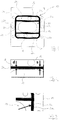
- Fig. 1 shows a molded seal 10 which is inserted into a groove 12 which is formed on a component 14 of a vacuum pump.
- the component 14 can, for example, be a base body of a turbo molecular pump to which a further component is attached, for example a lubricant pump.
- the component 14 has a series of channels 16, 18 and (fastening) bores 20 which are to be connected to corresponding channels or bores of the component to be fastened.
- the molded seal 10 is inserted into the groove 12 when the vacuum pump is installed.
- the one-piece molded seal 10 is used. This comprises a circumferential section 22 which is essentially square and has rounded corners. Web 24, which are connected to side sections 26a, 26b of the circumferential section 22, divide the area surrounded by the circumferential section 22 into three sealing areas 28a, 28b, 28c. Each sealing area 28a, 28b, 28c is sealed off from the exterior and from the respectively adjacent sealing area.
- the molded seal 10 has the advantage that only one component specially adapted for the present design is required, which can be precisely inserted into the groove 12.
- a thickness d of the web 24 is smaller than a width s of the corresponding section of the groove 12.
- the thickness d is slightly greater than the width s, so that the molded seal 10 is held in the groove 12 by clamping forces is.
- the clamping forces required to secure against unintentional falling out of the molded seal 10 are comparatively low, so that even a small oversize of the molded seal 10 in relation to the groove 12 ensures reliable fixing of the molded seal 10.
- the molded seal 10 is not provided in all areas with a greater thickness d than the width s of the groove 12. In many cases it is sufficient to provide only one or more sections in which the thickness d is greater than that Width s.
- the molded seal 10 is clamped into the groove 12. This is achieved, for example, in that the side sections 26a, 26b between the webs 24 are slightly shorter than the corresponding sections of the groove 12. Then the molded seal 10 has to be stretched a little in sections in order to be able to be inserted into the groove 12, whereby sections of the molded seal 10 are pressed against the insides of corresponding sections of the groove 12, which is shown in FIG Fig. 3 is indicated by an arrow.
- the same can also be achieved by an inverse construction, in which the molded seal 10 has, at least in sections, a certain oversize with respect to corresponding sections of the groove 12, so that parts of the molded seal 10 are pressed against an outside of the groove 12. In this case, the molded seal 10 must be slightly compressed in order to be able to be inserted into the groove 12.
- Fig. 4 makes it clear that it is not absolutely necessary to design the molded seal the same everywhere with regard to its thickness d.
- the webs 24 are made thinner than the peripheral section 22 (d2 ⁇ d1).
- certain areas of the circumferential section 22 be constricted or thickened. Thickenings can, for example, enable local terminal points.
- securing sections 30 can be provided, which is based on the in Fig. 5 Shown embodiment 10 "of the molded seal is explained.
- the securing sections 30 each comprise a web 24 'which connects a pin 32 to the peripheral section 22.
- the pins 32 are pressed into recesses provided for this purpose in the component 14 in order to the molded seal 10" in the To fix groove 12 or to make a contribution to their fixation.
- securing sections 30 are conceivable. These can be designed, for example, like tabs.
- the number, design and arrangement of the securing sections 30 to be provided depends, among other things, on the installation space available and the required reliability of the fixing.
- the molded seals 10, 10 ′, 10 ′′ described above define an essentially square base area which is divided into three sealing areas 28a, 28b, 28c by two straight and symmetrically arranged webs 24. Deviations from this configuration are entirely possible 22 have any geometry.
- the webs 24 do not necessarily have to be straight and can have any geometry.
- the configuration of the molded seal is dictated by the geometry of the areas to be sealed.
- the molded seal can have sections extending out of the plane of the image so that The molded seal is not an essentially flat structure (cf. molded seals 10, 10 ', 10 "), but rather has a three-dimensional structure.
- a closed sealing area 28d by means of a sealing section 34, the sealing section 34 being connected to the peripheral section 22 by at least one - for example, web-like - connecting section 36 (see molded seal 10 '"in Fig. 6 ).
- the sealing area 28d lies completely within the circumferential section 22, which encloses a sealing area 28e surrounding the sealing area 28d.
Description
Die vorliegende Erfindung betrifft eine Vakuumpumpe, insbesondere eine Turbomolekularpumpe, die ein erstes Bauteil und ein zweites Bauteil umfasst, die in einem endmontierten Zustand miteinander verbunden sind, wobei zur Abdichtung der Verbindung eine Dichtung vorgesehen ist.The present invention relates to a vacuum pump, in particular a turbomolecular pump, which comprises a first component and a second component, which are connected to one another in a final assembled state, a seal being provided to seal the connection.
Bei Vakuumpumpen ist die Thematik "Dichtigkeit" naturgemäß von zentraler Bedeutung. Zur Abdichtung von miteinander verbundenen Bauteilen der Vakuumpumpe werden eine Vielzahl von Dichtungen eingesetzt. Meist gilt es, Kanäle und/oder Komponenten eines Pumpraums der Pumpe sowie deren eingangs- und ausgangsseitigen Anschlüsse abzudichten. Aber auch in anderen Funktionsbereichen der Pumpe muss eine zuverlässige Abdichtung gewährleistet sein, beispielsweise im Bereich einer der Vakuumpumpe zugeordneten Schmiermittelpumpe. Zwischen dem Gehäuse der Vakuumpumpe und der Schmiermittelpumpe wird bisher ein O-Ring zur Abdichtung von Schmiermittelkanälen gegenüber dem Außenraum eingesetzt. Ein zweiter, kleinerer O-Ring verhindert, dass Schmiermittel zur Steuerplatine und sogar bis in den Motorraum der Pumpe gelangen kann.In the case of vacuum pumps, the subject of "tightness" is naturally of central importance. A large number of seals are used to seal interconnected components of the vacuum pump. Mostly, it is necessary to seal channels and / or components of a pump chamber of the pump and their inlet and outlet connections. However, reliable sealing must also be ensured in other functional areas of the pump, for example in the area of a lubricant pump assigned to the vacuum pump. Up to now, an O-ring has been used between the housing of the vacuum pump and the lubricant pump to seal lubricant channels from the outside. A second, smaller O-ring prevents lubricant from reaching the control board and even into the pump's engine compartment.
Die
Zur Abdichtung vor Verschmutzungen bei Vakuumpumpen wird auf die
In der Praxis rutscht insbesondere der kleinere O-Ring bei der Montage der Schmiermittelpumpe an der Vakuumpumpe leicht aus der vorgesehenen Position und es ist nicht ganz einfach, ihn korrekt zu platzieren. Es besteht also eine gewisse Gefahr, dass die Verbindung der beiden Komponenten Leckagestellen aufweist.In practice, the smaller O-ring in particular easily slips out of its intended position when the lubricant pump is mounted on the vacuum pump and it is not very easy to position it correctly. There is therefore a certain risk that the connection between the two components will have leakage points.
Außerdem müssen die verwendeten O-Ringe aufgrund der beengten Verhältnisse oftmals deformiert werden, um korrekt eingesetzt werden zu können. Nicht selten fallen die O-Ringe sogar bei der Vormontage herunter, was zu unnötigen Zeitverlusten führt.In addition, the O-rings used often have to be deformed due to the cramped conditions in order to be able to use them correctly. It is not uncommon for the O-rings to fall down during pre-assembly, which leads to unnecessary time losses.
Es ist daher eine Aufgabe der vorliegenden Erfindung, eine Vakuumpumpe zu schaffen, die zuverlässig und einfach zu montieren ist und deren Komponenten zuverlässig abgedichtet sind.It is therefore an object of the present invention to provide a vacuum pump which is reliable and easy to assemble and the components of which are reliably sealed.
Die Lösung dieser Aufgabe erfolgt durch eine Vakuumpumpe mit den Merkmalen des Anspruchs 1.This problem is solved by a vacuum pump with the features of
Erfindungsgemäß ist zur Abdichtung der Verbindung zwischen den beiden Bauteilen zumindest eine separate, einteilige Formdichtung vorgesehen, die zur Vormontage lösbar an einem der beiden Bauteile befestigbar ist und die zumindest zwei in Umfangsrichtung geschlossene Dichtbereiche definiert, die separat voneinander abzudichten sind. Der Querschnitt der Formdichtung variiert lokal.According to the invention, at least one separate, one-piece molded seal is provided to seal the connection between the two components, which can be releasably attached to one of the two components for pre-assembly and which defines at least two circumferentially closed sealing areas that are to be sealed separately from one another. The cross-section of the molded seal varies locally.
Erfindungsgemäß sind außerdem nicht zwei separate Dichtelemente vorgesehen, die die beiden Dichtbereiche gegenüber dem Außenraum und/oder gegeneinander abdichten.According to the invention, two separate sealing elements are also not provided, which seal the two sealing areas from the outside and / or from one another.
Erfindungsgemäß wird der Weg beschritten, eine an die jeweilige Konstruktion angepasste Formdichtung vorzusehen, die zwei oder mehr Dichtbereiche abdichtet. In einem einzigen Vormontageschritt lässt sich die Formdichtung an einem der beiden Bauteile anordnen. Die Verbindung Bauteil/Formdichtung ist dabei lösbar. so dass auch im Servicefall ein leichter Austausch der Formdichtung möglich ist. Da lediglich eine einzige, speziell angepasste Dichtung vorgesehen ist, kann die Montage der beiden Bauteile schnell, einfach und zuverlässig durchgeführt werden.According to the invention, the path is taken to provide a molded seal which is adapted to the respective construction and which seals two or more sealing areas. The molded seal can be arranged on one of the two components in a single pre-assembly step. The connection between component and molded seal can be released. so that the molded seal can also be easily replaced in the event of service. Since only a single, specially adapted seal is provided, the assembly of the two components can be carried out quickly, easily and reliably.
Weitere Ausführungsformen der Erfindung sind in der Beschreibung, den Ansprüchen und den beigefügten Zeichnungen angegeben.Further embodiments of the invention are indicated in the description, the claims and the accompanying drawings.
Gemäß einer Ausführungsform weist das erste Bauteil und/oder das zweite Bauteil eine Nut auf, in die die Formdichtung zur Vormontage zumindest abschnittsweise einbringbar ist. Insbesondere ist die Nut derart dimensioniert, dass die Formdichtung zumindest abschnittsweise in der Nut geklemmt und/oder verspannt ist. Eine Verklemmung kann beispielsweise dadurch erreicht werden, dass eine Breite der Nut in zumindest einem Abschnitt der Nut geringfügig kleiner ist als eine Dicke der Formdichtung in einem dem Abschnitt der Nut zugeordneten Abschnitt der Formdichtung. Mit anderen Worten ist bei dieser Ausführungsform eine Verengung der Nut - oder eine Verdickung der Formdichtung - vorgesehen, um die Formdichtung gegen ein unbeabsichtigtes Herausfallen zu sichern. Dabei ist es nicht notwendig, dass die Klemmung überall vorliegt. Grundsätzlich ist es ausreichend, wenn zumindest eine "Klemmstelle" vorgesehen ist. Eine "vollständige" Klemmung kann in bestimmten Fällen jedoch geeignet sein.According to one embodiment, the first component and / or the second component has a groove into which the molded seal can be introduced at least in sections for pre-assembly. In particular, the groove is dimensioned such that the molded seal is clamped and / or braced in the groove at least in sections. A jamming can be achieved, for example, in that a width of the groove in at least one section of the groove is slightly smaller than a thickness of the molded seal in a section of the molded seal assigned to the section of the groove. In other words, a narrowing of the groove - or a thickening of the molded seal - is provided in this embodiment in order to secure the molded seal against accidentally falling out. It is not necessary that the clamping is present everywhere. In principle, it is sufficient if at least one "clamping point" is provided. However, "full" clamping may be appropriate in certain cases.
Zusätzlich oder alternativ kann der Verlauf der Nut derart gewählt sein, dass die Formdichtung in einem in die Nut eingebrachten Zustand gedehnt oder gestaucht ist. Beispielsweise ist ein Verspannen erzeugbar, wenn ein Nutabschnitt, der einen der beiden geschlossenen Dichtbereiche zugeordnet ist, etwas länger ist, als der entsprechende Abschnitt der Formdichtung. Zum Einbringen dieses Abschnitts der Formdichtung muss diese folglich gedehnt werden, wodurch die Formdichtung gegen eine Innenwand der Nut gepresst wird. Grundsätzlich ist auch eine inverse Ausgestaltung möglich, bei der zumindest ein einen der beiden Dichtbereiche definierender Abschnitt der Formdichtung gestaucht und gegen eine Außenwand der Nut gepresst wird.Additionally or alternatively, the course of the groove can be selected in such a way that the molded seal is stretched or compressed when it is introduced into the groove. For example, bracing can be generated if a groove section that is assigned to one of the two closed sealing areas is somewhat longer than the corresponding section of the molded seal. In order to introduce this section of the molded seal, it must consequently be stretched, whereby the molded seal is pressed against an inner wall of the groove. In principle, an inverse configuration is also possible, in which at least one section of the molded seal that defines one of the two sealing areas is upset and pressed against an outer wall of the groove.
Eine weitere Maßnahme, die - alleine oder in Kombination mit den vorstehend beschriebenen Maßnahmen - dazu dienen kann, ein unbeabsichtigtes Herausfallen der Formdichtung zu verhindern, besteht darin, an dem ersten und/oder dem zweiten Bauteil zumindest eine Ausnehmung vorzusehen, in die ein Sicherungsabschnitt der Formdichtung zumindest abschnittsweise einbringbar ist. Die Ausnehmung ist dabei insbesondere derart dimensioniert, dass der Sicherungsabschnitt in der Ausnehmung geklemmt ist. Der Sicherungsabschnitt kann beispielsweise laschenförmig ausgebildet sein und/oder einen Steg umfassen, an dessen Ende ein verdickter Zapfen angeordnet ist. Dieser kann in die vorstehend genannte Ausnehmung gedrückt werden, um die Formdichtung lösbar an dem ersten oder dem zweiten Bauteil zu sichern.Another measure, which - alone or in combination with the measures described above - can serve to prevent the molded seal from accidentally falling out, is to provide at least one recess on the first and / or the second component into which a securing section of the Form seal can be introduced at least in sections. The recess is dimensioned in particular such that the securing section is clamped in the recess. The securing section can, for example, be designed in the form of a tab and / or comprise a web, at the end of which a thickened pin is arranged. This can be pressed into the recess mentioned above in order to releasably secure the molded seal on the first or the second component.
Gemäß einer weiteren Ausführungsform weist die Formdichtung einen Umfangsabschnitt auf, der die Dichtbereiche in Umfangsrichtung gemeinsam umschließt. Der von dem Umfangsabschnitt umschlossene Bereich ist durch zumindest einen mit dem Umfangsabschnitt verbundenen Teilungsabschnitt in die zumindest zwei separaten Dichtbereiche aufgeteilt. Es versteht sich, dass grundsätzlich eine beliebige Anzahl von Teilungsabschnitten und beliebig geformte Teilungsabschnitte vorgesehen sein können, um die benötigte Anzahl und Formgebung der Dichtbereiche zu erhalten.According to a further embodiment, the molded seal has a peripheral section which jointly surrounds the sealing areas in the peripheral direction. The area enclosed by the circumferential section is divided into the at least two separate sealing areas by at least one dividing section connected to the circumferential section. It goes without saying that, in principle, any number of dividing sections and dividing sections of any shape can be provided in order to obtain the required number and shape of the sealing areas.
Der Teilungsabschnitt kann stegartig ausgebildet sein. Insbesondere erstreckt er sich im Wesentlichen geradlinig.The dividing section can be designed like a web. In particular, it extends essentially in a straight line.
In vielen Fällen ist es vorteilhaft, wenn der Teilungsabschnitt einen kleineren Querschnitt aufweist als der Umfangsabschnitt. Der Umfangsabschnitt kann eine im Wesentlichen rechteckige, insbesondere quadratische Grundform aufweisen. Die Ecken der vorstehend genannten Grundform können abgerundet sein. Es versteht sich jedoch, dass auch beliebige andere Grundformen denkbar sind.In many cases it is advantageous if the dividing section has a smaller cross section than the peripheral section. The peripheral section can have an essentially rectangular, in particular square, basic shape. The corners of the basic shape mentioned above can be rounded. It goes without saying, however, that any other basic shapes are also conceivable.
Ein runder, ovaler, quadratischer oder rechteckiger Querschnitt der Formdichtung bietet in vielen Fällen gute Dichteigenschaften bei vergleichsweise günstigen Herstellungskosten. Für spezielle Anwendungen kann der Querschnitt der Formdichtung jedoch auch komplexer sein.A round, oval, square or rectangular cross section of the molded seal offers good sealing properties in many cases at comparatively low manufacturing costs. For special applications, however, the cross-section of the molded seal can also be more complex.
Oftmals weisen die zu verbindenden Bauteile jeweils ebene Verbindungsflächen auf, so dass eine sich in Wesentlichen in einer Ebene erstreckende Formdichtung als geeignet erweist. Die Formdichtung kann jedoch auch beliebige dreidimensionale Formgebungen aufweisen, um komplexen Anschlussgeometrien der beiden Bauteile Rechnung zu tragen.The components to be connected often each have flat connecting surfaces, so that a molded seal extending essentially in one plane proves to be suitable. However, the molded seal can also have any three-dimensional shape in order to take into account complex connection geometries of the two components.
Insbesondere ist das erste Bauteil ein Grundkörper oder Gehäusebauteil der Vakuumpumpe.In particular, the first component is a base body or housing component of the vacuum pump.
Nachfolgend wird die Erfindung rein beispielhaft anhand vorteilhafter Ausführungsformen unter Bezugnahme auf die beigefügten Zeichnungen erläutert. Es zeigen:
- Fig. 1
- eine Formdichtung gemäß einer Ausführungsform der erfindungsgemäßen Vakuumpumpe,
- Fig. 2 und 3
- Vergrößerungen von Abschnitten der in
Fig. 1 gezeigten Formdichtung und - Fig. 4 bis 6
- weitere Ausführungsformen der Formdichtung einer erfindungsgemäßen Vakuumpumpe.
- Fig. 1
- a molded seal according to an embodiment of the vacuum pump according to the invention,
- Figs. 2 and 3
- Enlargements of sections of the in
Fig. 1 Shaped seal and - Figures 4 to 6
- further embodiments of the molded seal of a vacuum pump according to the invention.
Um die Kanäle 16, 18 gegeneinander und gegenüber dem Außenraum abzudichten, wird die Formdichtung 10 bei der Montage der Vakuumpumpe in die Nut 12 eingesetzt. Anstelle herkömmlicher separater Dichtungen, die die Kanäle 16, 18 separat umgeben und abdichten, wird die einteilige Formdichtung 10 verwendet. Diese umfasst einen Umfangsabschnitt 22, der im Wesentlichen quadratisch ausgebildet ist und abgerundete Ecken aufweist. Stege 24, die mit Seitenabschnitten 26a, 26b des Umfangsabschnitts 22 verbunden sind, teilen den durch den Umfangsabschnitt 22 umgebenen Bereich in drei Dichtbereiche 28a, 28b, 28c auf. Jeder Dichtbereich 28a, 28b, 28c ist gegenüber dem Außenraum und gegenüber dem jeweils benachbarten Dichtbereich abgedichtet.In order to seal the
Gegenüber der herkömmlichen Bauweise, separate Dichtringe vorzusehen, weist die Formdichtung 10 den Vorteil auf, dass lediglich eine speziell für die vorliegende Konstruktion angepasste Komponente benötigt wird, die sich präzise in die Nut 12 einsetzen lässt.Compared to the conventional design of providing separate sealing rings, the molded
In
Alternativ oder zusätzlich kann vorgesehen sein, dass die Formdichtung 10 in die Nut 12 eingespannt wird. Dies wird beispielsweise dadurch erreicht, dass die Seitenabschnitte 26a, 26b zwischen den Stegen 24 etwas kürzer sind als die entsprechenden Abschnitte der Nut 12. Dann muss nämlich die Formdichtung 10 abschnittsweise etwas gedehnt werden, um in die Nut 12 eingesetzt werden zu können, wodurch Abschnitte der Formdichtung 10 an die Innenseiten entsprechender Abschnitte der Nut 12 gepresst werden, was in
Die vorstehend beschriebenen Konstruktionsprinzipien können auch auf andere Bereiche der Formdichtung 10 - oder auf diese als Ganzes - angewendet werden.The construction principles described above can also be applied to other areas of the molded seal 10 - or to this as a whole.
Alternativ oder zusätzlich zu den vorstehend beschriebenen Fixierungsmöglichkeiten mittels Klemmwirkung, Dehnung und/oder Stauchung können Sicherungsabschnitte 30 vorgesehen sein, was anhand der in
Alternative Ausgestaltungen und/oder Anordnungen der Sicherungsabschnitte 30 sind denkbar. Diese können beispielsweise laschenartig ausgebildet sein. Die Anzahl, Ausgestaltung und Anordnung der vorzusehenden Sicherungsabschnitte 30 hängt unter anderem von dem zur Verfügung stehenden Bauraum und der erforderlichen Zuverlässigkeit der Fixierung ab.Alternative configurations and / or arrangements of the securing
Die vorstehend beschriebenen Formdichtungen 10, 10', 10" definieren eine im Wesentlichen quadratische Grundfläche, die durch zwei gerade und symmetrisch angeordnete Stege 24 in drei Dichtbereiche 28a, 28b, 28c aufgeteilt wird. Abweichungen von dieser Ausgestaltung sind durchaus möglich. Beispielsweise kann der Umfangsabschnitt 22 eine beliebige Geometrie aufweisen. Die Stege 24 müssen nicht zwingend geradlinig sein und können eine beliebige Geometrie aufweisen. Letztlich wird die Ausgestaltung der Formdichtung durch die Geometrie der abzudichtenden Bereiche diktiert. Die Formdichtung kann sich aus der Bildebene heraus erstreckende Abschnitte aufweisen, so dass die Formdichtung keine im Wesentlichen ebene Struktur ist (vgl. Formdichtungen 10, 10', 10"), sondern eine dreidimensionale Struktur aufweist.The molded seals 10, 10 ′, 10 ″ described above define an essentially square base area which is divided into three sealing
Grundsätzlich ist es auch denkbar, durch einen Dichtungsabschnitt 34 einen geschlossenen Dichtbereich 28d zu begrenzen, wobei der Dichtungsabschnitt 34 mit zumindest einem - z.B. stegartigen - Verbindungsabschnitt 36 mit dem Umfangsabschnitt 22 verbunden ist (siehe Formdichtung 10'" in
- 10, 10', 10", 10'"10, 10 ', 10 ", 10'"
- FormdichtungMolded seal
- 1212
- NutGroove
- 1414th
- BauteilComponent
- 1616
- Kanalchannel
- 1818th
- Kanalchannel
- 2020th
- Bohrungdrilling
- 2222nd
- UmfangsabschnittCircumferential section
- 24, 24'24, 24 '
- Stegweb
- 26a, 26b26a, 26b
- SeitenabschnittSide section
- 28a, 28b, 28c, 28d, 28e28a, 28b, 28c, 28d, 28e
- DichtbereichSealing area
- 3030th
- SicherungsabschnittFuse section
- 3232
- PinPin code
- 3434
- DichtungsabschnittSealing section
- 3636
- VerbindungsabschnittConnection section
- d, d1, d2d, d1, d2
- Dickethickness
- ss
- Breitewidth
Claims (14)
- A vacuum pump, in particular a turbomolecular pump, comprising a first component (14) and a second component which are connected to one another in a final assembled state, wherein at least one separate, single-part molded seal (10, 10', 10", 10"') is provided for sealing the connection of the components and is releasably fastenable to one of the two components (14) for a pre-assembly, characterized in that
the molded seal (10, 10', 10", 10'") defines at least two sealing regions (28a, 28b, 28c, 28d, 28e) which are closed in the peripheral direction and which are to be sealed separately from one another; and in that
a cross-section of the molded seal (10, 10', 10", 10'") varies locally. - A vacuum pump in accordance with claim 1,
characterized in that
the first component (14) and/or the second component has/have a groove (12) into which the molded seal (10, 10', 10", 10'") can be at least sectionally inserted for a pre-assembly. - A vacuum pump in accordance with claim 2,
characterized in that
the groove (12) is dimensioned such that the molded seal (10, 10', 10", 10'") is at least sectionally clamped and/or tensioned in the groove (12). - A vacuum pump in accordance with claim 3,
characterized in that
a width (s) of the groove (12) in at least one section of the groove (12) is slightly smaller than the thickness (d) of the molded seal (10, 10', 10", 10'") in a section of the molded seal (10, 10', 10", 10'") associated with the section of the groove (12). - A vacuum pump in accordance with claim 3 or claim 4,
characterized in that
the course of the groove (12) is selected such that the molded seal (10, 10', 10", 10"') is stretched or compressed in a state inserted into the groove (12). - A vacuum pump in accordance with at least one of the preceding claims,
characterized in that
the first component (14) and/or the second component has/have at least one recess into which a securing section (30) of the molded seal (10") can be at least sectionally inserted for a pre-assembly, in particular with the recess being dimensioned such that the securing section (30) is clamped in the recess. - A vacuum pump in accordance with claim 6,
characterized in that
the securing section is lug-shaped and/or comprises a web (24') at whose end a thickened pin (32) is arranged. - A vacuum pump in accordance with at least one of the preceding claims,
characterized in that
the molded seal (10, 10', 10", 10'") has a peripheral section (22) which jointly surrounds the sealing regions (28a, 28b, 28c, 28d, 28e) in the peripheral direction, with the region surrounded by the peripheral section (22) being divided into the separate sealing regions (28a, 28b, 28c or 28d, 28e) by at least one division section (24, 34) connected to the peripheral section (22). - A vacuum pump in accordance with claim 8,
characterized in that
the division section (24, 34) is formed in a web-like manner, in particular in a straight line. - A vacuum pump in accordance with claim 8 or claim 9,
characterized in that
the division section (24, 24) has a smaller cross-section than the peripheral section (22). - A vacuum pump in accordance with at least one of the preceding claims 8 to 10,
characterized in that
the peripheral section (22) has a substantially rectangular basic shape, in particular a square basic shape. - A vacuum pump in accordance with at least one of the preceding claims,
characterized in that
a cross-section of the molded seal (10, 10', 10", 10"') is round, oval, square or rectangular. - A vacuum pump in accordance with at least one of the preceding claims,
characterized in that
the molded seal (10, 10', 10", 10'") extends substantially in one plane; or in that the molded seal has a three-dimensional geometry. - A vacuum pump in accordance with at least one of the preceding claims,
characterized in that
the first component (14) is a base body or a housing component of the vacuum pump.
Priority Applications (1)
| Application Number | Priority Date | Filing Date | Title |
|---|---|---|---|
| EP15182200.4A EP3135917B1 (en) | 2015-08-24 | 2015-08-24 | Vacuum pump |
Applications Claiming Priority (1)
| Application Number | Priority Date | Filing Date | Title |
|---|---|---|---|
| EP15182200.4A EP3135917B1 (en) | 2015-08-24 | 2015-08-24 | Vacuum pump |
Publications (2)
| Publication Number | Publication Date |
|---|---|
| EP3135917A1 EP3135917A1 (en) | 2017-03-01 |
| EP3135917B1 true EP3135917B1 (en) | 2020-10-07 |
Family
ID=53969286
Family Applications (1)
| Application Number | Title | Priority Date | Filing Date |
|---|---|---|---|
| EP15182200.4A Active EP3135917B1 (en) | 2015-08-24 | 2015-08-24 | Vacuum pump |
Country Status (1)
| Country | Link |
|---|---|
| EP (1) | EP3135917B1 (en) |
Families Citing this family (1)
| Publication number | Priority date | Publication date | Assignee | Title |
|---|---|---|---|---|
| EP3470681B1 (en) | 2017-10-10 | 2021-09-22 | Pfeiffer Vacuum Gmbh | Electric feedthrough for a vacuum device, in the form of a pcb |
Citations (1)
| Publication number | Priority date | Publication date | Assignee | Title |
|---|---|---|---|---|
| EP2975268A2 (en) * | 2014-07-17 | 2016-01-20 | Pfeiffer Vacuum Gmbh | Vacuum system |
Family Cites Families (5)
| Publication number | Priority date | Publication date | Assignee | Title |
|---|---|---|---|---|
| DE4230710C2 (en) * | 1992-09-14 | 1995-02-02 | Goetze Ag | Device for sealing between the oil pan and crankcase of an internal combustion engine |
| US6460859B1 (en) * | 2000-04-12 | 2002-10-08 | Parker-Hannifin Corporation | Resilient elastomer and metal retainer gasket for sealing between curved surfaces |
| EP2636905B1 (en) * | 2012-03-05 | 2015-07-08 | Sulzer Management AG | Sealing assembly and pump with a sealing assembly |
| WO2014049728A1 (en) * | 2012-09-26 | 2014-04-03 | 株式会社島津製作所 | Protective net for vacuum pump, manufacturing method for same, and vacuum pump |
| DE102013109637A1 (en) * | 2013-09-04 | 2015-03-05 | Pfeiffer Vacuum Gmbh | Vacuum pump and arrangement with a vacuum pump |
-
2015
- 2015-08-24 EP EP15182200.4A patent/EP3135917B1/en active Active
Patent Citations (1)
| Publication number | Priority date | Publication date | Assignee | Title |
|---|---|---|---|---|
| EP2975268A2 (en) * | 2014-07-17 | 2016-01-20 | Pfeiffer Vacuum Gmbh | Vacuum system |
Also Published As
| Publication number | Publication date |
|---|---|
| EP3135917A1 (en) | 2017-03-01 |
Similar Documents
| Publication | Publication Date | Title |
|---|---|---|
| EP3004702B1 (en) | Combination of a housing and a valve | |
| DE202006007821U1 (en) | Clamp or guide rail with captive protection for retaining bolts | |
| DE3817472A1 (en) | LOCK FOR A FLUIDIC CONNECTOR | |
| DE102014203913A1 (en) | Rifle | |
| EP2606233B1 (en) | Valve of a piston pump with a closing body | |
| DE102014100758B4 (en) | Play-free plug connection for pipe and hose lines | |
| DE102005058161B4 (en) | Quick release for the installation area | |
| EP3135917B1 (en) | Vacuum pump | |
| EP2715200B1 (en) | Play-free plug connection for pipe or tube lines | |
| EP1184572B1 (en) | High pressure seal | |
| DE10307529A1 (en) | Fuel filter for a motor vehicle's fuel injection system has a rod-shaped filter body guided on its ends in a supply channel | |
| EP3746692B1 (en) | Water pipe with pipe fitting | |
| DE202021102165U1 (en) | Attachment system | |
| EP2775178B1 (en) | Multipath valve block | |
| WO2001018362A1 (en) | Combination consisting of a main unit and of at least one external-mounted functional unit | |
| DE102009056336A1 (en) | Pipe coupling system, in particular for a tapping device | |
| EP3366851A1 (en) | Universal filling valve set | |
| EP2960402A1 (en) | Lock cylinder system | |
| EP3659222B1 (en) | Arrangement with two cabinet frames connected through a baying connector | |
| DE10218025B4 (en) | Throttling device, in particular for a high-pressure force injection device for an internal combustion engine | |
| WO2017178231A1 (en) | Control ring for surge arresters | |
| DE102017100331A1 (en) | Mounting arrangement for connecting components, component connection and scissor lift | |
| DE102016000494A1 (en) | Component assembly and this having air conditioning | |
| DE102016218565B4 (en) | Hydraulic system with a housing | |
| DE102021209233A1 (en) | ring seal |
Legal Events
| Date | Code | Title | Description |
|---|---|---|---|
| PUAI | Public reference made under article 153(3) epc to a published international application that has entered the european phase |
Free format text: ORIGINAL CODE: 0009012 |
|
| STAA | Information on the status of an ep patent application or granted ep patent |
Free format text: STATUS: THE APPLICATION HAS BEEN PUBLISHED |
|
| AK | Designated contracting states |
Kind code of ref document: A1 Designated state(s): AL AT BE BG CH CY CZ DE DK EE ES FI FR GB GR HR HU IE IS IT LI LT LU LV MC MK MT NL NO PL PT RO RS SE SI SK SM TR |
|
| AX | Request for extension of the european patent |
Extension state: BA ME |
|
| STAA | Information on the status of an ep patent application or granted ep patent |
Free format text: STATUS: REQUEST FOR EXAMINATION WAS MADE |
|
| 17P | Request for examination filed |
Effective date: 20170718 |
|
| RBV | Designated contracting states (corrected) |
Designated state(s): AL AT BE BG CH CY CZ DE DK EE ES FI FR GB GR HR HU IE IS IT LI LT LU LV MC MK MT NL NO PL PT RO RS SE SI SK SM TR |
|
| STAA | Information on the status of an ep patent application or granted ep patent |
Free format text: STATUS: EXAMINATION IS IN PROGRESS |
|
| 17Q | First examination report despatched |
Effective date: 20190822 |
|
| GRAP | Despatch of communication of intention to grant a patent |
Free format text: ORIGINAL CODE: EPIDOSNIGR1 |
|
| STAA | Information on the status of an ep patent application or granted ep patent |
Free format text: STATUS: GRANT OF PATENT IS INTENDED |
|
| INTG | Intention to grant announced |
Effective date: 20200630 |
|
| GRAS | Grant fee paid |
Free format text: ORIGINAL CODE: EPIDOSNIGR3 |
|
| GRAA | (expected) grant |
Free format text: ORIGINAL CODE: 0009210 |
|
| STAA | Information on the status of an ep patent application or granted ep patent |
Free format text: STATUS: THE PATENT HAS BEEN GRANTED |
|
| AK | Designated contracting states |
Kind code of ref document: B1 Designated state(s): AL AT BE BG CH CY CZ DE DK EE ES FI FR GB GR HR HU IE IS IT LI LT LU LV MC MK MT NL NO PL PT RO RS SE SI SK SM TR |
|
| REG | Reference to a national code |
Ref country code: GB Ref legal event code: FG4D Free format text: NOT ENGLISH |
|
| REG | Reference to a national code |
Ref country code: CH Ref legal event code: EP Ref country code: AT Ref legal event code: REF Ref document number: 1321430 Country of ref document: AT Kind code of ref document: T Effective date: 20201015 |
|
| REG | Reference to a national code |
Ref country code: DE Ref legal event code: R096 Ref document number: 502015013591 Country of ref document: DE |
|
| REG | Reference to a national code |
Ref country code: IE Ref legal event code: FG4D Free format text: LANGUAGE OF EP DOCUMENT: GERMAN |
|
| REG | Reference to a national code |
Ref country code: NL Ref legal event code: MP Effective date: 20201007 |
|
| PG25 | Lapsed in a contracting state [announced via postgrant information from national office to epo] |
Ref country code: RS Free format text: LAPSE BECAUSE OF FAILURE TO SUBMIT A TRANSLATION OF THE DESCRIPTION OR TO PAY THE FEE WITHIN THE PRESCRIBED TIME-LIMIT Effective date: 20201007 Ref country code: FI Free format text: LAPSE BECAUSE OF FAILURE TO SUBMIT A TRANSLATION OF THE DESCRIPTION OR TO PAY THE FEE WITHIN THE PRESCRIBED TIME-LIMIT Effective date: 20201007 Ref country code: NO Free format text: LAPSE BECAUSE OF FAILURE TO SUBMIT A TRANSLATION OF THE DESCRIPTION OR TO PAY THE FEE WITHIN THE PRESCRIBED TIME-LIMIT Effective date: 20210107 Ref country code: NL Free format text: LAPSE BECAUSE OF FAILURE TO SUBMIT A TRANSLATION OF THE DESCRIPTION OR TO PAY THE FEE WITHIN THE PRESCRIBED TIME-LIMIT Effective date: 20201007 Ref country code: PT Free format text: LAPSE BECAUSE OF FAILURE TO SUBMIT A TRANSLATION OF THE DESCRIPTION OR TO PAY THE FEE WITHIN THE PRESCRIBED TIME-LIMIT Effective date: 20210208 Ref country code: GR Free format text: LAPSE BECAUSE OF FAILURE TO SUBMIT A TRANSLATION OF THE DESCRIPTION OR TO PAY THE FEE WITHIN THE PRESCRIBED TIME-LIMIT Effective date: 20210108 |
|
| REG | Reference to a national code |
Ref country code: LT Ref legal event code: MG4D |
|
| PG25 | Lapsed in a contracting state [announced via postgrant information from national office to epo] |
Ref country code: ES Free format text: LAPSE BECAUSE OF FAILURE TO SUBMIT A TRANSLATION OF THE DESCRIPTION OR TO PAY THE FEE WITHIN THE PRESCRIBED TIME-LIMIT Effective date: 20201007 Ref country code: BG Free format text: LAPSE BECAUSE OF FAILURE TO SUBMIT A TRANSLATION OF THE DESCRIPTION OR TO PAY THE FEE WITHIN THE PRESCRIBED TIME-LIMIT Effective date: 20210107 Ref country code: IS Free format text: LAPSE BECAUSE OF FAILURE TO SUBMIT A TRANSLATION OF THE DESCRIPTION OR TO PAY THE FEE WITHIN THE PRESCRIBED TIME-LIMIT Effective date: 20210207 Ref country code: PL Free format text: LAPSE BECAUSE OF FAILURE TO SUBMIT A TRANSLATION OF THE DESCRIPTION OR TO PAY THE FEE WITHIN THE PRESCRIBED TIME-LIMIT Effective date: 20201007 Ref country code: LV Free format text: LAPSE BECAUSE OF FAILURE TO SUBMIT A TRANSLATION OF THE DESCRIPTION OR TO PAY THE FEE WITHIN THE PRESCRIBED TIME-LIMIT Effective date: 20201007 Ref country code: SE Free format text: LAPSE BECAUSE OF FAILURE TO SUBMIT A TRANSLATION OF THE DESCRIPTION OR TO PAY THE FEE WITHIN THE PRESCRIBED TIME-LIMIT Effective date: 20201007 |
|
| PG25 | Lapsed in a contracting state [announced via postgrant information from national office to epo] |
Ref country code: HR Free format text: LAPSE BECAUSE OF FAILURE TO SUBMIT A TRANSLATION OF THE DESCRIPTION OR TO PAY THE FEE WITHIN THE PRESCRIBED TIME-LIMIT Effective date: 20201007 |
|
| REG | Reference to a national code |
Ref country code: DE Ref legal event code: R097 Ref document number: 502015013591 Country of ref document: DE |
|
| PG25 | Lapsed in a contracting state [announced via postgrant information from national office to epo] |
Ref country code: EE Free format text: LAPSE BECAUSE OF FAILURE TO SUBMIT A TRANSLATION OF THE DESCRIPTION OR TO PAY THE FEE WITHIN THE PRESCRIBED TIME-LIMIT Effective date: 20201007 Ref country code: SM Free format text: LAPSE BECAUSE OF FAILURE TO SUBMIT A TRANSLATION OF THE DESCRIPTION OR TO PAY THE FEE WITHIN THE PRESCRIBED TIME-LIMIT Effective date: 20201007 Ref country code: RO Free format text: LAPSE BECAUSE OF FAILURE TO SUBMIT A TRANSLATION OF THE DESCRIPTION OR TO PAY THE FEE WITHIN THE PRESCRIBED TIME-LIMIT Effective date: 20201007 Ref country code: SK Free format text: LAPSE BECAUSE OF FAILURE TO SUBMIT A TRANSLATION OF THE DESCRIPTION OR TO PAY THE FEE WITHIN THE PRESCRIBED TIME-LIMIT Effective date: 20201007 Ref country code: LT Free format text: LAPSE BECAUSE OF FAILURE TO SUBMIT A TRANSLATION OF THE DESCRIPTION OR TO PAY THE FEE WITHIN THE PRESCRIBED TIME-LIMIT Effective date: 20201007 |
|
| PLBE | No opposition filed within time limit |
Free format text: ORIGINAL CODE: 0009261 |
|
| STAA | Information on the status of an ep patent application or granted ep patent |
Free format text: STATUS: NO OPPOSITION FILED WITHIN TIME LIMIT |
|
| PG25 | Lapsed in a contracting state [announced via postgrant information from national office to epo] |
Ref country code: DK Free format text: LAPSE BECAUSE OF FAILURE TO SUBMIT A TRANSLATION OF THE DESCRIPTION OR TO PAY THE FEE WITHIN THE PRESCRIBED TIME-LIMIT Effective date: 20201007 |
|
| 26N | No opposition filed |
Effective date: 20210708 |
|
| PG25 | Lapsed in a contracting state [announced via postgrant information from national office to epo] |
Ref country code: AL Free format text: LAPSE BECAUSE OF FAILURE TO SUBMIT A TRANSLATION OF THE DESCRIPTION OR TO PAY THE FEE WITHIN THE PRESCRIBED TIME-LIMIT Effective date: 20201007 |
|
| PG25 | Lapsed in a contracting state [announced via postgrant information from national office to epo] |
Ref country code: SI Free format text: LAPSE BECAUSE OF FAILURE TO SUBMIT A TRANSLATION OF THE DESCRIPTION OR TO PAY THE FEE WITHIN THE PRESCRIBED TIME-LIMIT Effective date: 20201007 |
|
| REG | Reference to a national code |
Ref country code: CH Ref legal event code: PL |
|
| PG25 | Lapsed in a contracting state [announced via postgrant information from national office to epo] |
Ref country code: MC Free format text: LAPSE BECAUSE OF FAILURE TO SUBMIT A TRANSLATION OF THE DESCRIPTION OR TO PAY THE FEE WITHIN THE PRESCRIBED TIME-LIMIT Effective date: 20201007 |
|
| REG | Reference to a national code |
Ref country code: BE Ref legal event code: MM Effective date: 20210831 |
|
| PG25 | Lapsed in a contracting state [announced via postgrant information from national office to epo] |
Ref country code: LI Free format text: LAPSE BECAUSE OF NON-PAYMENT OF DUE FEES Effective date: 20210831 Ref country code: CH Free format text: LAPSE BECAUSE OF NON-PAYMENT OF DUE FEES Effective date: 20210831 |
|
| PG25 | Lapsed in a contracting state [announced via postgrant information from national office to epo] |
Ref country code: IS Free format text: LAPSE BECAUSE OF FAILURE TO SUBMIT A TRANSLATION OF THE DESCRIPTION OR TO PAY THE FEE WITHIN THE PRESCRIBED TIME-LIMIT Effective date: 20210207 Ref country code: LU Free format text: LAPSE BECAUSE OF NON-PAYMENT OF DUE FEES Effective date: 20210824 |
|
| PG25 | Lapsed in a contracting state [announced via postgrant information from national office to epo] |
Ref country code: IE Free format text: LAPSE BECAUSE OF NON-PAYMENT OF DUE FEES Effective date: 20210824 Ref country code: FR Free format text: LAPSE BECAUSE OF NON-PAYMENT OF DUE FEES Effective date: 20210831 Ref country code: BE Free format text: LAPSE BECAUSE OF NON-PAYMENT OF DUE FEES Effective date: 20210831 |
|
| REG | Reference to a national code |
Ref country code: AT Ref legal event code: MM01 Ref document number: 1321430 Country of ref document: AT Kind code of ref document: T Effective date: 20210824 |
|
| PG25 | Lapsed in a contracting state [announced via postgrant information from national office to epo] |
Ref country code: AT Free format text: LAPSE BECAUSE OF NON-PAYMENT OF DUE FEES Effective date: 20210824 |
|
| PG25 | Lapsed in a contracting state [announced via postgrant information from national office to epo] |
Ref country code: HU Free format text: LAPSE BECAUSE OF FAILURE TO SUBMIT A TRANSLATION OF THE DESCRIPTION OR TO PAY THE FEE WITHIN THE PRESCRIBED TIME-LIMIT; INVALID AB INITIO Effective date: 20150824 |
|
| PG25 | Lapsed in a contracting state [announced via postgrant information from national office to epo] |
Ref country code: CY Free format text: LAPSE BECAUSE OF FAILURE TO SUBMIT A TRANSLATION OF THE DESCRIPTION OR TO PAY THE FEE WITHIN THE PRESCRIBED TIME-LIMIT Effective date: 20201007 |
|
| PGFP | Annual fee paid to national office [announced via postgrant information from national office to epo] |
Ref country code: IT Payment date: 20230825 Year of fee payment: 9 Ref country code: GB Payment date: 20230822 Year of fee payment: 9 Ref country code: CZ Payment date: 20230815 Year of fee payment: 9 |
|
| PGFP | Annual fee paid to national office [announced via postgrant information from national office to epo] |
Ref country code: DE Payment date: 20231027 Year of fee payment: 9 |