EP3135870A1 - System for suppressing acoustic noise within a gas turbine combustor - Google Patents
System for suppressing acoustic noise within a gas turbine combustor Download PDFInfo
- Publication number
- EP3135870A1 EP3135870A1 EP16184595.3A EP16184595A EP3135870A1 EP 3135870 A1 EP3135870 A1 EP 3135870A1 EP 16184595 A EP16184595 A EP 16184595A EP 3135870 A1 EP3135870 A1 EP 3135870A1
- Authority
- EP
- European Patent Office
- Prior art keywords
- baffle plate
- air plenum
- outer casing
- air
- combustion chamber
- Prior art date
- Legal status (The legal status is an assumption and is not a legal conclusion. Google has not performed a legal analysis and makes no representation as to the accuracy of the status listed.)
- Withdrawn
Links
- 230000005534 acoustic noise Effects 0.000 title claims abstract description 7
- 238000002485 combustion reaction Methods 0.000 claims abstract description 100
- 239000012530 fluid Substances 0.000 claims abstract description 31
- 230000003068 static effect Effects 0.000 claims abstract description 27
- 238000004891 communication Methods 0.000 claims abstract description 26
- 238000011144 upstream manufacturing Methods 0.000 claims abstract description 18
- 238000000605 extraction Methods 0.000 claims description 19
- 239000007789 gas Substances 0.000 description 33
- 239000000567 combustion gas Substances 0.000 description 8
- 239000000446 fuel Substances 0.000 description 8
- 230000010355 oscillation Effects 0.000 description 8
- 239000000203 mixture Substances 0.000 description 3
- 239000011153 ceramic matrix composite Substances 0.000 description 2
- 238000001816 cooling Methods 0.000 description 2
- 238000012986 modification Methods 0.000 description 2
- 230000004048 modification Effects 0.000 description 2
- 230000009467 reduction Effects 0.000 description 2
- 230000008878 coupling Effects 0.000 description 1
- 238000010168 coupling process Methods 0.000 description 1
- 238000005859 coupling reaction Methods 0.000 description 1
- 238000013016 damping Methods 0.000 description 1
- 230000000694 effects Effects 0.000 description 1
- 230000002708 enhancing effect Effects 0.000 description 1
- 230000005284 excitation Effects 0.000 description 1
- 239000000463 material Substances 0.000 description 1
- 229910001092 metal group alloy Inorganic materials 0.000 description 1
- 238000000034 method Methods 0.000 description 1
- 230000000116 mitigating effect Effects 0.000 description 1
- 230000037361 pathway Effects 0.000 description 1
- 230000001902 propagating effect Effects 0.000 description 1
- 230000001141 propulsive effect Effects 0.000 description 1
- 238000004513 sizing Methods 0.000 description 1
- 230000001052 transient effect Effects 0.000 description 1
Images


Classifications
-
- F—MECHANICAL ENGINEERING; LIGHTING; HEATING; WEAPONS; BLASTING
- F02—COMBUSTION ENGINES; HOT-GAS OR COMBUSTION-PRODUCT ENGINE PLANTS
- F02C—GAS-TURBINE PLANTS; AIR INTAKES FOR JET-PROPULSION PLANTS; CONTROLLING FUEL SUPPLY IN AIR-BREATHING JET-PROPULSION PLANTS
- F02C7/00—Features, components parts, details or accessories, not provided for in, or of interest apart form groups F02C1/00 - F02C6/00; Air intakes for jet-propulsion plants
- F02C7/04—Air intakes for gas-turbine plants or jet-propulsion plants
- F02C7/045—Air intakes for gas-turbine plants or jet-propulsion plants having provisions for noise suppression
-
- F—MECHANICAL ENGINEERING; LIGHTING; HEATING; WEAPONS; BLASTING
- F02—COMBUSTION ENGINES; HOT-GAS OR COMBUSTION-PRODUCT ENGINE PLANTS
- F02C—GAS-TURBINE PLANTS; AIR INTAKES FOR JET-PROPULSION PLANTS; CONTROLLING FUEL SUPPLY IN AIR-BREATHING JET-PROPULSION PLANTS
- F02C7/00—Features, components parts, details or accessories, not provided for in, or of interest apart form groups F02C1/00 - F02C6/00; Air intakes for jet-propulsion plants
- F02C7/24—Heat or noise insulation
-
- F—MECHANICAL ENGINEERING; LIGHTING; HEATING; WEAPONS; BLASTING
- F01—MACHINES OR ENGINES IN GENERAL; ENGINE PLANTS IN GENERAL; STEAM ENGINES
- F01D—NON-POSITIVE DISPLACEMENT MACHINES OR ENGINES, e.g. STEAM TURBINES
- F01D25/00—Component parts, details, or accessories, not provided for in, or of interest apart from, other groups
- F01D25/04—Antivibration arrangements
-
- F—MECHANICAL ENGINEERING; LIGHTING; HEATING; WEAPONS; BLASTING
- F01—MACHINES OR ENGINES IN GENERAL; ENGINE PLANTS IN GENERAL; STEAM ENGINES
- F01D—NON-POSITIVE DISPLACEMENT MACHINES OR ENGINES, e.g. STEAM TURBINES
- F01D9/00—Stators
- F01D9/02—Nozzles; Nozzle boxes; Stator blades; Guide conduits, e.g. individual nozzles
-
- F—MECHANICAL ENGINEERING; LIGHTING; HEATING; WEAPONS; BLASTING
- F02—COMBUSTION ENGINES; HOT-GAS OR COMBUSTION-PRODUCT ENGINE PLANTS
- F02C—GAS-TURBINE PLANTS; AIR INTAKES FOR JET-PROPULSION PLANTS; CONTROLLING FUEL SUPPLY IN AIR-BREATHING JET-PROPULSION PLANTS
- F02C3/00—Gas-turbine plants characterised by the use of combustion products as the working fluid
- F02C3/04—Gas-turbine plants characterised by the use of combustion products as the working fluid having a turbine driving a compressor
-
- F—MECHANICAL ENGINEERING; LIGHTING; HEATING; WEAPONS; BLASTING
- F02—COMBUSTION ENGINES; HOT-GAS OR COMBUSTION-PRODUCT ENGINE PLANTS
- F02C—GAS-TURBINE PLANTS; AIR INTAKES FOR JET-PROPULSION PLANTS; CONTROLLING FUEL SUPPLY IN AIR-BREATHING JET-PROPULSION PLANTS
- F02C3/00—Gas-turbine plants characterised by the use of combustion products as the working fluid
- F02C3/14—Gas-turbine plants characterised by the use of combustion products as the working fluid characterised by the arrangement of the combustion chamber in the plant
-
- F—MECHANICAL ENGINEERING; LIGHTING; HEATING; WEAPONS; BLASTING
- F02—COMBUSTION ENGINES; HOT-GAS OR COMBUSTION-PRODUCT ENGINE PLANTS
- F02C—GAS-TURBINE PLANTS; AIR INTAKES FOR JET-PROPULSION PLANTS; CONTROLLING FUEL SUPPLY IN AIR-BREATHING JET-PROPULSION PLANTS
- F02C7/00—Features, components parts, details or accessories, not provided for in, or of interest apart form groups F02C1/00 - F02C6/00; Air intakes for jet-propulsion plants
- F02C7/04—Air intakes for gas-turbine plants or jet-propulsion plants
-
- F—MECHANICAL ENGINEERING; LIGHTING; HEATING; WEAPONS; BLASTING
- F02—COMBUSTION ENGINES; HOT-GAS OR COMBUSTION-PRODUCT ENGINE PLANTS
- F02C—GAS-TURBINE PLANTS; AIR INTAKES FOR JET-PROPULSION PLANTS; CONTROLLING FUEL SUPPLY IN AIR-BREATHING JET-PROPULSION PLANTS
- F02C9/00—Controlling gas-turbine plants; Controlling fuel supply in air- breathing jet-propulsion plants
- F02C9/16—Control of working fluid flow
- F02C9/18—Control of working fluid flow by bleeding, bypassing or acting on variable working fluid interconnections between turbines or compressors or their stages
-
- F—MECHANICAL ENGINEERING; LIGHTING; HEATING; WEAPONS; BLASTING
- F23—COMBUSTION APPARATUS; COMBUSTION PROCESSES
- F23R—GENERATING COMBUSTION PRODUCTS OF HIGH PRESSURE OR HIGH VELOCITY, e.g. GAS-TURBINE COMBUSTION CHAMBERS
- F23R3/00—Continuous combustion chambers using liquid or gaseous fuel
- F23R3/02—Continuous combustion chambers using liquid or gaseous fuel characterised by the air-flow or gas-flow configuration
- F23R3/04—Air inlet arrangements
-
- F—MECHANICAL ENGINEERING; LIGHTING; HEATING; WEAPONS; BLASTING
- F23—COMBUSTION APPARATUS; COMBUSTION PROCESSES
- F23R—GENERATING COMBUSTION PRODUCTS OF HIGH PRESSURE OR HIGH VELOCITY, e.g. GAS-TURBINE COMBUSTION CHAMBERS
- F23R3/00—Continuous combustion chambers using liquid or gaseous fuel
- F23R3/42—Continuous combustion chambers using liquid or gaseous fuel characterised by the arrangement or form of the flame tubes or combustion chambers
-
- F—MECHANICAL ENGINEERING; LIGHTING; HEATING; WEAPONS; BLASTING
- F05—INDEXING SCHEMES RELATING TO ENGINES OR PUMPS IN VARIOUS SUBCLASSES OF CLASSES F01-F04
- F05D—INDEXING SCHEME FOR ASPECTS RELATING TO NON-POSITIVE-DISPLACEMENT MACHINES OR ENGINES, GAS-TURBINES OR JET-PROPULSION PLANTS
- F05D2220/00—Application
- F05D2220/30—Application in turbines
- F05D2220/32—Application in turbines in gas turbines
-
- F—MECHANICAL ENGINEERING; LIGHTING; HEATING; WEAPONS; BLASTING
- F05—INDEXING SCHEMES RELATING TO ENGINES OR PUMPS IN VARIOUS SUBCLASSES OF CLASSES F01-F04
- F05D—INDEXING SCHEME FOR ASPECTS RELATING TO NON-POSITIVE-DISPLACEMENT MACHINES OR ENGINES, GAS-TURBINES OR JET-PROPULSION PLANTS
- F05D2220/00—Application
- F05D2220/30—Application in turbines
- F05D2220/36—Application in turbines specially adapted for the fan of turbofan engines
-
- F—MECHANICAL ENGINEERING; LIGHTING; HEATING; WEAPONS; BLASTING
- F05—INDEXING SCHEMES RELATING TO ENGINES OR PUMPS IN VARIOUS SUBCLASSES OF CLASSES F01-F04
- F05D—INDEXING SCHEME FOR ASPECTS RELATING TO NON-POSITIVE-DISPLACEMENT MACHINES OR ENGINES, GAS-TURBINES OR JET-PROPULSION PLANTS
- F05D2240/00—Components
- F05D2240/20—Rotors
- F05D2240/24—Rotors for turbines
-
- F—MECHANICAL ENGINEERING; LIGHTING; HEATING; WEAPONS; BLASTING
- F05—INDEXING SCHEMES RELATING TO ENGINES OR PUMPS IN VARIOUS SUBCLASSES OF CLASSES F01-F04
- F05D—INDEXING SCHEME FOR ASPECTS RELATING TO NON-POSITIVE-DISPLACEMENT MACHINES OR ENGINES, GAS-TURBINES OR JET-PROPULSION PLANTS
- F05D2240/00—Components
- F05D2240/35—Combustors or associated equipment
-
- F—MECHANICAL ENGINEERING; LIGHTING; HEATING; WEAPONS; BLASTING
- F05—INDEXING SCHEMES RELATING TO ENGINES OR PUMPS IN VARIOUS SUBCLASSES OF CLASSES F01-F04
- F05D—INDEXING SCHEME FOR ASPECTS RELATING TO NON-POSITIVE-DISPLACEMENT MACHINES OR ENGINES, GAS-TURBINES OR JET-PROPULSION PLANTS
- F05D2260/00—Function
- F05D2260/96—Preventing, counteracting or reducing vibration or noise
- F05D2260/963—Preventing, counteracting or reducing vibration or noise by Helmholtz resonators
-
- F—MECHANICAL ENGINEERING; LIGHTING; HEATING; WEAPONS; BLASTING
- F05—INDEXING SCHEMES RELATING TO ENGINES OR PUMPS IN VARIOUS SUBCLASSES OF CLASSES F01-F04
- F05D—INDEXING SCHEME FOR ASPECTS RELATING TO NON-POSITIVE-DISPLACEMENT MACHINES OR ENGINES, GAS-TURBINES OR JET-PROPULSION PLANTS
- F05D2260/00—Function
- F05D2260/96—Preventing, counteracting or reducing vibration or noise
- F05D2260/964—Preventing, counteracting or reducing vibration or noise counteracting thermoacoustic noise
-
- F—MECHANICAL ENGINEERING; LIGHTING; HEATING; WEAPONS; BLASTING
- F23—COMBUSTION APPARATUS; COMBUSTION PROCESSES
- F23R—GENERATING COMBUSTION PRODUCTS OF HIGH PRESSURE OR HIGH VELOCITY, e.g. GAS-TURBINE COMBUSTION CHAMBERS
- F23R2900/00—Special features of, or arrangements for continuous combustion chambers; Combustion processes therefor
- F23R2900/00014—Reducing thermo-acoustic vibrations by passive means, e.g. by Helmholtz resonators
-
- Y—GENERAL TAGGING OF NEW TECHNOLOGICAL DEVELOPMENTS; GENERAL TAGGING OF CROSS-SECTIONAL TECHNOLOGIES SPANNING OVER SEVERAL SECTIONS OF THE IPC; TECHNICAL SUBJECTS COVERED BY FORMER USPC CROSS-REFERENCE ART COLLECTIONS [XRACs] AND DIGESTS
- Y02—TECHNOLOGIES OR APPLICATIONS FOR MITIGATION OR ADAPTATION AGAINST CLIMATE CHANGE
- Y02T—CLIMATE CHANGE MITIGATION TECHNOLOGIES RELATED TO TRANSPORTATION
- Y02T50/00—Aeronautics or air transport
- Y02T50/60—Efficient propulsion technologies, e.g. for aircraft
Definitions
- the present subject matter relates generally to a gas turbine engine. More particularly, the present subject matter relates to a system for suppressing acoustic noise within a combustor of the gas turbine engine.
- a high-bypass type turbofan engine generally includes a fan section and a core gas turbine engine.
- the gas turbine engine includes, in serial flow order, a low pressure compressor, a high pressure compressor, a combustion section, a high pressure turbine and a low pressure turbine.
- a high pressure shaft couples the high pressure compressor to the high pressure turbine.
- a low pressure shaft extends coaxially within the high pressure shaft and couples the low pressure compressor to the low pressure turbine.
- the fan section includes a plurality of fan blades coupled to a fan shaft and disposed upstream from an inlet of the low pressure compressor.
- the fan shaft may be coupled to the low pressure shaft either directly or indirectly, for example, via a gearbox.
- an outer casing or nacelle circumscribes the fan blades and at least a portion of the gas turbine engine.
- a bypass air passage is defined between an outer casing of the gas turbine engine and the nacelle.
- the air flowing though the inlet is progressively compressed as it flows through the low pressure compressor and the high pressure compressor, thus providing a highly compressed air to a diffuser cavity or head end portion of the combustion section.
- a portion of the compressed air flows into a combustion chamber of the combustion section.
- Fuel is injected into the combustion chamber via one or more fuel injectors.
- the fuel and air mixture is burned to provide combustion gases.
- the combustion gases are routed from the combustion chamber through the high pressure turbine, thus rotatably driving the high pressure compressor via the high pressure shaft.
- the combustion gases then flow aft through the low pressure turbine, thereby rotatably driving the low pressure compressor and the fan blades via the low pressure shaft and the fan shaft.
- the combustion gases are exhausted from the gas turbine via an exhaust nozzle, thus providing a portion of total thrust of the turbofan engine.
- These pressure oscillations generate acoustic waves that may propagate downstream from the combustion chamber towards the high pressure turbine and/or upstream from the combustion chamber back towards the diffuser cavity and/or the compressor outlet.
- Low frequency to intermediate frequency combustion dynamics such as those that occur during engine startup and/or during a low power to idle operating condition may negatively impact compressor stall margin, reduce operability margin of the turbofan engine and/or may increase external combustion noise or growl.
- higher frequency combustion dynamics 250-1000Hz
- a system for suppressing combustion dynamics within a combustion section of a gas turbine engine would be useful.
- the present subject matter is directed to a system for suppressing acoustic noise within a combustion section of a gas turbine.
- the system includes at least one static structure disposed forward of a combustion chamber defined within the combustion section.
- the static structure at least partially defines a diffuser cavity upstream of the combustion chamber.
- a baffle plate is coupled to the static structure.
- the baffle plate and the static structure at least partially define an air plenum within the combustion section forward of the combustion chamber.
- the baffle plate includes an aperture that provides for fluid communication between the diffuser cavity and the air plenum.
- the at least one static structure and the baffle plate define a Helmholtz resonator within the combustion section.
- the gas turbine includes an outer casing that at least partially encases an annular combustor.
- the outer casing at least partially defines a diffuser cavity that is upstream from a combustion chamber of the annular combustor.
- a compressor diffuser body extends at least partially into the diffuser cavity.
- a baffle plate extends radially between the compressor diffuser body and the outer casing and circumferentially within the outer casing.
- the baffle plate, the compressor diffuser body and the outer casing at least partially define an air plenum within the outer casing forward of the combustion chamber.
- the baffle plate includes and/or defines an aperture that provides for fluid communication between the diffuser cavity and the air plenum.
- the air plenum at least partially defines a Helmholtz resonator within the outer casing.
- the Turbofan engine includes a gas turbine engine having, in serial flow order, a low pressure compressor, a high pressure compressor, a combustion section including an annular combustor encased within an outer casing, a high pressure turbine and a low pressure turbine.
- the combustion section further comprises a diffuser cavity that is upstream from a combustion chamber of the annular combustor, at least a portion of a compressor diffuser body that extends into the diffuser cavity and a baffle plate that extends radially between the compressor diffuser body and the outer casing and circumferentially within the outer casing.
- the baffle plate, the compressor diffuser body and the outer casing at least partially define an air plenum within the outer casing forward of the combustion chamber.
- the baffle plate includes a plurality of apertures that provide for fluid communication between the diffuser cavity and the air plenum.
- the air plenum at least partially defines a Helmholtz resonator within the combustion section.
- upstream refers to the flow direction from which the fluid flows
- downstream refers to the flow direction to which the fluid flows.
- FIG. 1 is a schematic partially cross-sectioned side view of an exemplary high by-pass turbofan jet engine 10 herein referred to as "turbofan 10" as may incorporate various embodiments of the present invention.
- the turbofan 10 has a longitudinal or axial centerline axis 12 that extends therethrough for reference purposes.
- the turbofan 10 may include a fan assembly 14 and a core turbine engine or gas turbine engine 16 disposed downstream from the fan assembly 14.
- the gas turbine engine 16 may generally include a substantially tubular outer casing 18 that defines an annular inlet 20.
- the outer casing 18 encases or at least partially forms, in serial flow relationship, a compressor section having a booster or low pressure (LP) compressor 22, a high pressure (HP) compressor 24, a combustion section 26, a turbine section including a high pressure (HP) turbine 28, a low pressure (LP) turbine 30 and a jet exhaust nozzle section 32.
- a high pressure (HP) rotor shaft 34 drivingly connects the HP turbine 28 to the HP compressor 24.
- a low pressure (LP) rotor shaft 36 drivingly connects the LP turbine 30 to the LP compressor 22.
- the LP rotor shaft 36 may also be connected to a fan shaft 38 of the fan assembly 14.
- the LP rotor shaft 36 may be connected to the fan shaft 38 via a reduction gear 40 such as in an indirect-drive or geared-drive configuration.
- the fan assembly 14 includes a plurality of fan blades 42 that are coupled to and that extend radially outwardly from the fan shaft 38.
- An annular fan casing or nacelle 44 circumferentially surrounds the fan assembly 14 and/or at least a portion of the gas turbine engine 16.
- the nacelle 44 may be configured to be supported relative to the gas turbine engine 16 by a plurality of circumferentially-spaced outlet guide vanes or struts 46.
- at least a portion of the nacelle 44 may extend over an outer portion of the gas turbine engine 16 so as to define a bypass airflow passage 48 therebetween.
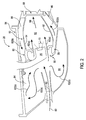
- FIG. 2 is a cross sectional side view of an exemplary combustion section 26 of the gas turbine engine 16 as shown in FIG. 1 , as may incorporate various embodiments of the present invention.
- the combustion section 26 may generally include an annular type combustor 50 having an annular inner liner 52, an annular outer liner 54 and a generally domed end 56 that extends radially between upstream ends 58, 60 of the inner liner 52 and the outer liner 54 respectfully.
- the inner liner 52 is radially spaced from the outer liner 54 with respect to engine centerline 12 ( FIG. 1 ) and defines a generally annular combustion chamber 62 therebetween.
- the inner liner 52 and/or the outer liner 54 may be at least partially or entirely formed from metal alloys or ceramic matrix composite (CMC) materials.
- CMC ceramic matrix composite
- the inner liner 52 and the outer liner 54 may be encased within a combustor or outer casing 64.
- An outer flow passage 66 may be defined around the inner liner 52 and/or the outer liner 54.
- the inner liner 52 and the outer liner 54 may extend from the domed end 56 towards a turbine nozzle or inlet 68 to the HP turbine 28 ( FIG. 1 ), thus at least partially defining a hot gas path between the combustor 50 and the HP turbine 28.
- a fuel injector or nozzle 70 may extend at least partially through the domed end 56 and provides a fuel 72 to the combustion chamber 62.
- a volume of air as indicated schematically by arrows 74 enters the turbofan 10 through an associated inlet 76 of the nacelle 44 and/or fan assembly 14.
- a portion of the air as indicated schematically by arrows 78 is directed or routed into the bypass airflow passage 48 while another portion of the air as indicated schematically by arrow 80 is directed or routed into the LP compressor 22.
- Air 80 is progressively compressed as it flows through the LP and HP compressors 22, 24 towards the combustion section 26.
- the now compressed air as indicated schematically by arrows 82 flows into a diffuser cavity or head end portion 84 of the combustion section 26.
- the compressed air 82 pressurizes the diffuser cavity 84.
- a first portion of the of the compressed air 82 flows from the diffuser cavity 84 into the combustion chamber 62 where it is mixed with the fuel 72 and burned, thus generating combustion gases, as indicated schematically by arrows 86, within the combustor 50.
- the LP and HP compressors 22, 24 provide more compressed air to the diffuser cavity 84 than is needed for combustion. Therefore, a second portion of the compressed air 82 as indicated schematically by arrows 82(b) may be used for various purposes other than combustion. For example, as shown in FIG.
- compressed air 82(b) may be routed into the outer flow passage 66 to provide cooling to the inner and outer liners 52, 54.
- at least a portion of compressed air 82(b) may be routed out of the diffuser cavity 84.
- a portion of compressed air 82(b) may be directed through various flow passages to provide cooling air to at least one of the HP turbine 28 or the LP turbine 30.
- the combustion gases 86 generated in the combustion chamber 62 flow from the combustor 50 into the HP turbine 28, thus causing the HP rotor shaft 34 to rotate, thereby supporting operation of the HP compressor 24.
- the combustion gases 86 are then routed through the LP turbine 30, thus causing the LP rotor shaft 36 to rotate, thereby supporting operation of the LP compressor 22 and/or rotation of the fan shaft 38.
- the combustion gases 86 are then exhausted through the jet exhaust nozzle section 32 of the gas turbine engine 16 to provide propulsive thrust.
- pressure oscillations occur within the combustion chamber 62. These pressure oscillations may be driven, at least in part, by a coupling between the flame's unsteady heat release dynamics, the overall acoustics of the combustor and transient fluid dynamics within the combustor 50.
- the pressure oscillations generally result in undesirable high-amplitude, self-sustaining pressure oscillations within the combustor 50. These pressure oscillations may result in intense, frequently single-frequency acoustic waves that may propagate within the generally closed combustion section 26.
- these pressure oscillations may generate acoustic waves at frequencies ranging from about 50Hz to about 1000Hz or even higher. These acoustic waves may propagate downstream from the combustion chamber 62 towards the high pressure turbine 28 and/or upstream from the combustion chamber 62 back towards the diffuser cavity 84 and/or the outlet of the HP compressor 24.
- low frequency acoustic waves such as those that occur during engine startup and/or during a low power to idle operating condition and/or higher frequency waves (250-100Hz) which may occur during takeoff and other operating conditions may reduce operability margin of the turbofan engine and/or may increase external combustion noise or growl.
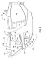
- FIG. 3 is a cross sectional side view of the exemplary combustion section 26 of the gas turbine engine 16 as shown in FIG. 2 , according to at least one embodiment of the present invention.
- the combustion section 26 includes a system 100 for suppressing acoustic noise within the combustion section 26 of the gas turbine engine 16.
- the system 100 as provided herein defines a Helmholtz resonator within the combustion section 26 that is tuned to a target frequency.
- the system 100 includes one or more static structures or walls 102 that at least partially define the diffuser cavity 84, a baffle plate 104 that extends radially between the one or more static structures 102 and circumferentially within the outer casing 64 of the combustion section 26, and a bleed air plenum 106 defined between the baffle plate 104 and the one or more static structures 102.
- the system 100 further includes a bleed-air extraction port 108 that provides for fluid communication out of the air plenum 106.
- the one or more static structures 102, the baffle plate 104 and the air plenum 106 are disposed and/or defined within the combustion section 26 downstream from the HP compressor 24 ( FIG. 1 ) and forward of and/or upstream from the fuel injector 70 and the combustion chamber 62 ( FIG. 2 ).
- the one or more static structures 102 may comprise, at least in part, a portion of a compressor diffuser body 110 of the HP compressor 24 and a portion 112 of the outer casing 64 that surrounds the combustion section 26.
- the air plenum 106 has a volume "VP" that is distinct from a volume "VC" of the diffuser cavity 84.
- the bleed-air extraction port 108 defines a flow passage that extends from the air plenum through the outer casing 64.
- the bleed-air extraction port 108 may be fluidly connected to various components of the turbofan 10 and/or to various components of an associated aircraft (not shown).
- the baffle plate 104 includes and/or defines one or more apertures or openings 114 that provide for fluid communication between the diffuser cavity 84 and the air plenum 106.
- FIG. 4 provides a front view of the baffle plate 104 as shown in FIG. 3 , according to at least one embodiment of the present disclosure.
- the baffle plate may include a plurality of the apertures 114.
- the apertures 114 may be size similarly or may be sized differently.
- the apertures 114 may have any shape and are not limited to any particular shape unless otherwise specified in the claims.
- the apertures 114 may be generally circular, generally triangular, generally rectangular/square or generally oval.
- the system 100 may include at least one resonator tube or resonator tube 116 that extends from an inner surface 118 of the baffle into the air plenum 106.
- the system 100 may include a plurality of resonator tubes 116 that extend from the inner surface 118 of the baffle into the air plenum 106.
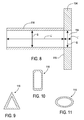
- FIG. 8 provides a cross sectioned side view of a portion of the baffle plate 104 and an exemplary resonator tube 116 according to at least one embodiment of the present disclosure. As shown in FIG.
- the resonator tubes 116 may be generally hollow or tubular and may be generally aligned with and in fluid communication with a corresponding aperture 114, thus providing for fluid communication through the resonator tube 116 between the diffuser cavity 84 ( FIG. 3 ) and the air plenum 106 ( FIG. 3 ).
- the resonator tubes 116 or the orifice 114 can have equal or non-equal size and may have unequal distribution circumferentially or radially.
- the resonator tube(s) 116 may have any shape and are not limited to any particular shape unless otherwise specified in the claims.
- the resonator tube(s) 116 may be generally circular, generally triangular, generally rectangular/square or generally oval.
- the air plenum 106 and the aperture(s) 114 the resonator tube(s) must be sized appropriately.
- L' may be equal to the thickness of the baffle 104 at the aperture 114 location and S is equal to the opening area of the aperture 114.
- the system 100 defines a Helmholtz resonator within the combustion section 26 that is tuned to a target frequency.
- the Helmholtz resonator is tuned by appropriately sizing the baffle plate 104, the aperture(s) 114 and the resonator tube(s) 116.
- a portion of compressed air 82(b) and the acoustic waves generated by the combustion process flow through the aperture(s) 114 in the baffle plate 104 and through the resonator tube(s) 116 into the air plenum 106.
- the bleed-air cavity 106 acts as a Helmholtz resonator within the combustion section 26 forward of and/or upstream from the fuel injector 70 and the combustion chamber 62.
- the aperture(s) 114 and/or the resonator tube(s) 116 allow for tuning of the Helmholtz resonator to suppress the target frequencies such as the low frequency acoustic waves (50-250Hz) and/or the higher frequency waves (250-1000Hz) generated within the combustion chamber 62 and propagating within the combustion section 26.
- Flow form the bleed-air extraction port 108 may be modulated to bias the flow out of bleed-air plenum, thus further enhancing the dampening effects of the system 100.
- system 100 may provide various technical advantages over existing combustor dampening systems.
- system 100 is formed as an integral part of existing combustor architecture, therefore no additional space is required within the combustion section 26.
- the system 100 is relatively easily configurable to fit existing combustion systems and is uniquely tunable to target frequencies of a specific combustion system.
- the system 100 as provided herein is positioned upstream or forward of the combustion chamber 62, thereby reducing potential thermal issues associated with placing damping systems downstream from the combustion chamber 62.
- Other advantages of the system 100 may include reduction of compressor operability margins typically required for combustor noise or growl, mitigation of the need to use pilot/main split for combustor noise or growl control at sub-idle and idle conditions.
Landscapes
- Engineering & Computer Science (AREA)
- Chemical & Material Sciences (AREA)
- Combustion & Propulsion (AREA)
- Mechanical Engineering (AREA)
- General Engineering & Computer Science (AREA)
- Physics & Mathematics (AREA)
- Fluid Mechanics (AREA)
- Structures Of Non-Positive Displacement Pumps (AREA)
Abstract
Description
- The present subject matter relates generally to a gas turbine engine. More particularly, the present subject matter relates to a system for suppressing acoustic noise within a combustor of the gas turbine engine.
- A high-bypass type turbofan engine generally includes a fan section and a core gas turbine engine. The gas turbine engine includes, in serial flow order, a low pressure compressor, a high pressure compressor, a combustion section, a high pressure turbine and a low pressure turbine. A high pressure shaft couples the high pressure compressor to the high pressure turbine. A low pressure shaft extends coaxially within the high pressure shaft and couples the low pressure compressor to the low pressure turbine.
- The fan section includes a plurality of fan blades coupled to a fan shaft and disposed upstream from an inlet of the low pressure compressor. The fan shaft may be coupled to the low pressure shaft either directly or indirectly, for example, via a gearbox. In particular configurations, an outer casing or nacelle circumscribes the fan blades and at least a portion of the gas turbine engine. A bypass air passage is defined between an outer casing of the gas turbine engine and the nacelle.
- In operation, air flows across the fan blades and towards the bypass air passage. A portion of the air flows into the inlet of the low pressure compressor while the remainder of the air is routed through the bypass passage. The air flowing though the inlet is progressively compressed as it flows through the low pressure compressor and the high pressure compressor, thus providing a highly compressed air to a diffuser cavity or head end portion of the combustion section. A portion of the compressed air flows into a combustion chamber of the combustion section. Fuel is injected into the combustion chamber via one or more fuel injectors. The fuel and air mixture is burned to provide combustion gases. The combustion gases are routed from the combustion chamber through the high pressure turbine, thus rotatably driving the high pressure compressor via the high pressure shaft. The combustion gases then flow aft through the low pressure turbine, thereby rotatably driving the low pressure compressor and the fan blades via the low pressure shaft and the fan shaft. The combustion gases are exhausted from the gas turbine via an exhaust nozzle, thus providing a portion of total thrust of the turbofan engine.
- As the fuel-air mixture burns, pressure oscillations or "combustion dynamics", driven at least in part by heat release during the combustion process, occur within the combustion chamber. These pressure oscillations generate acoustic waves that may propagate downstream from the combustion chamber towards the high pressure turbine and/or upstream from the combustion chamber back towards the diffuser cavity and/or the compressor outlet.
- Low frequency to intermediate frequency combustion dynamics (50-250Hz) such as those that occur during engine startup and/or during a low power to idle operating condition may negatively impact compressor stall margin, reduce operability margin of the turbofan engine and/or may increase external combustion noise or growl. In addition or in the alternative higher frequency combustion dynamics (250-1000Hz) such as those that may occur during operation of the combustor may result in excitation of turbine blades or cause other vibration related issues. Consequently, a system for suppressing combustion dynamics within a combustion section of a gas turbine engine would be useful.
- Aspects and advantages of the invention will be set forth in part in the following description, or may be obvious from the description, or may be learned through practice of the invention.
- In one aspect the present subject matter is directed to a system for suppressing acoustic noise within a combustion section of a gas turbine. The system includes at least one static structure disposed forward of a combustion chamber defined within the combustion section. The static structure at least partially defines a diffuser cavity upstream of the combustion chamber. A baffle plate is coupled to the static structure. The baffle plate and the static structure at least partially define an air plenum within the combustion section forward of the combustion chamber. The baffle plate includes an aperture that provides for fluid communication between the diffuser cavity and the air plenum. The at least one static structure and the baffle plate define a Helmholtz resonator within the combustion section.
- Another aspect of the present subject matter is directed to a gas turbine engine. The gas turbine includes an outer casing that at least partially encases an annular combustor. The outer casing at least partially defines a diffuser cavity that is upstream from a combustion chamber of the annular combustor. A compressor diffuser body extends at least partially into the diffuser cavity. A baffle plate extends radially between the compressor diffuser body and the outer casing and circumferentially within the outer casing. The baffle plate, the compressor diffuser body and the outer casing at least partially define an air plenum within the outer casing forward of the combustion chamber. The baffle plate includes and/or defines an aperture that provides for fluid communication between the diffuser cavity and the air plenum. The air plenum at least partially defines a Helmholtz resonator within the outer casing.
- Another aspect of the present disclosure is directed to a high by-pass turbofan engine. The Turbofan engine includes a gas turbine engine having, in serial flow order, a low pressure compressor, a high pressure compressor, a combustion section including an annular combustor encased within an outer casing, a high pressure turbine and a low pressure turbine. The combustion section further comprises a diffuser cavity that is upstream from a combustion chamber of the annular combustor, at least a portion of a compressor diffuser body that extends into the diffuser cavity and a baffle plate that extends radially between the compressor diffuser body and the outer casing and circumferentially within the outer casing. The baffle plate, the compressor diffuser body and the outer casing at least partially define an air plenum within the outer casing forward of the combustion chamber. The baffle plate includes a plurality of apertures that provide for fluid communication between the diffuser cavity and the air plenum. The air plenum at least partially defines a Helmholtz resonator within the combustion section.
- These and other features, aspects and advantages of the present invention will become better understood with reference to the following description and appended claims. The accompanying drawings, which are incorporated in and constitute a part of this specification, illustrate aspects of the invention and, together with the description, serve to explain the principles of the invention.
- A full and enabling disclosure of the present invention, including the best mode thereof, directed to one of ordinary skill in the art, is set forth in the specification, which makes reference to the appended figures, in which:
-
FIG. 1 is a schematic cross-sectional view of an exemplary high-bypass turbofan jet engine as may incorporate various embodiments of the present invention; -
FIG. 2 is a cross sectional side view of a combustion section of the high by-pass turbofan jet engine as shown inFIG. 1 , as may incorporate various embodiments of the present invention; -
FIG. 3 is a cross sectional side view of a combustion section of the high by-pass turbofan jet engine as shown inFIG. 2 , according to at least one embodiment of the present invention; -
FIG. 4 is an enlarged view of an exemplary baffle plate according to at least one embodiment of the present invention; -
FIG. 5 provides an exemplary cross sectional shape of an aperture of the baffle plate as shown inFIG. 4 , according to an exemplary embodiment of the present invention; -
FIG. 6 provides an exemplary cross sectional shape of an aperture of the baffle plate as shown inFIG. 4 , according to an exemplary embodiment of the present invention; -
FIG. 7 provides an exemplary cross sectional shape of an aperture of the baffle plate as shown inFIG. 4 , according to an exemplary embodiment of the present invention; -
FIG. 8 is an enlarged cross sectional view of a portion of the baffle plate as shown in -
FIG. 4 including an exemplary resonator tube, according to at least one embodiment of the present invention; -
FIG. 9 provides an exemplary cross sectional shape of a resonator tube, according to an exemplary embodiment of the present invention; -
FIG. 10 provides an exemplary cross sectional shape of a resonator tube, according to an exemplary embodiment of the present invention; and -
FIG. 11 provides an exemplary cross sectional shape of a resonator tube, according to an exemplary embodiment of the present invention. - Reference will now be made in detail to present embodiments of the invention, one or more examples of which are illustrated in the accompanying drawings. The detailed description uses numerical and letter designations to refer to features in the drawings. Like or similar designations in the drawings and description have been used to refer to like or similar parts of the invention. As used herein, the terms "first", "second", and "third" may be used interchangeably to distinguish one component from another and are not intended to signify location or importance of the individual components. The terms "upstream" and "downstream" refer to the relative flow direction with respect to fluid flow in a fluid pathway. For example, "upstream" refers to the flow direction from which the fluid flows, and "downstream" refers to the flow direction to which the fluid flows.
- Each example is provided by way of explanation of the invention, not limitation of the invention. In fact, it will be apparent to those skilled in the art that modifications and variations can be made in the present invention without departing from the scope thereof. For instance, features illustrated or described as part of one embodiment may be used on another embodiment to yield a still further embodiment. Thus, it is intended that the present invention covers such modifications and variations as come within the scope of the appended claims and their equivalents.
- Referring now to the drawings, wherein identical numerals indicate the same elements throughout the figures,
FIG. 1 is a schematic partially cross-sectioned side view of an exemplary high by-passturbofan jet engine 10 herein referred to as "turbofan 10" as may incorporate various embodiments of the present invention. As shown inFIG. 1 , theturbofan 10 has a longitudinal oraxial centerline axis 12 that extends therethrough for reference purposes. In general, theturbofan 10 may include afan assembly 14 and a core turbine engine orgas turbine engine 16 disposed downstream from thefan assembly 14. - The
gas turbine engine 16 may generally include a substantially tubularouter casing 18 that defines anannular inlet 20. Theouter casing 18 encases or at least partially forms, in serial flow relationship, a compressor section having a booster or low pressure (LP)compressor 22, a high pressure (HP)compressor 24, acombustion section 26, a turbine section including a high pressure (HP)turbine 28, a low pressure (LP)turbine 30 and a jetexhaust nozzle section 32. A high pressure (HP)rotor shaft 34 drivingly connects theHP turbine 28 to theHP compressor 24. A low pressure (LP)rotor shaft 36 drivingly connects theLP turbine 30 to theLP compressor 22. TheLP rotor shaft 36 may also be connected to afan shaft 38 of thefan assembly 14. In particular embodiments, as shown inFIG. 1 , theLP rotor shaft 36 may be connected to thefan shaft 38 via areduction gear 40 such as in an indirect-drive or geared-drive configuration. - As shown in
FIG. 1 , thefan assembly 14 includes a plurality offan blades 42 that are coupled to and that extend radially outwardly from thefan shaft 38. An annular fan casing ornacelle 44 circumferentially surrounds thefan assembly 14 and/or at least a portion of thegas turbine engine 16. It should be appreciated by those of ordinary skill in the art that thenacelle 44 may be configured to be supported relative to thegas turbine engine 16 by a plurality of circumferentially-spaced outlet guide vanes or struts 46. Moreover, at least a portion of thenacelle 44 may extend over an outer portion of thegas turbine engine 16 so as to define abypass airflow passage 48 therebetween. -
FIG. 2 is a cross sectional side view of anexemplary combustion section 26 of thegas turbine engine 16 as shown inFIG. 1 , as may incorporate various embodiments of the present invention. As shown inFIG. 2 , thecombustion section 26 may generally include anannular type combustor 50 having an annularinner liner 52, an annularouter liner 54 and a generallydomed end 56 that extends radially between upstream ends 58, 60 of theinner liner 52 and theouter liner 54 respectfully. As shown inFIG. 2 , theinner liner 52 is radially spaced from theouter liner 54 with respect to engine centerline 12 (FIG. 1 ) and defines a generallyannular combustion chamber 62 therebetween. In particular embodiments, theinner liner 52 and/or theouter liner 54 may be at least partially or entirely formed from metal alloys or ceramic matrix composite (CMC) materials. - As shown in
FIG. 2 , theinner liner 52 and theouter liner 54 may be encased within a combustor orouter casing 64. Anouter flow passage 66 may be defined around theinner liner 52 and/or theouter liner 54. Theinner liner 52 and theouter liner 54 may extend from thedomed end 56 towards a turbine nozzle orinlet 68 to the HP turbine 28 (FIG. 1 ), thus at least partially defining a hot gas path between the combustor 50 and theHP turbine 28. A fuel injector ornozzle 70 may extend at least partially through thedomed end 56 and provides afuel 72 to thecombustion chamber 62. - During operation of the
turbofan 10, as shown inFIGS. 1 and2 collectively, a volume of air as indicated schematically byarrows 74 enters theturbofan 10 through an associatedinlet 76 of thenacelle 44 and/orfan assembly 14. As theair 74 passes across the fan blades 42 a portion of the air as indicated schematically byarrows 78 is directed or routed into thebypass airflow passage 48 while another portion of the air as indicated schematically byarrow 80 is directed or routed into theLP compressor 22.Air 80 is progressively compressed as it flows through the LP andHP compressors combustion section 26. As shown inFIG. 2 , the now compressed air as indicated schematically byarrows 82 flows into a diffuser cavity orhead end portion 84 of thecombustion section 26. - The
compressed air 82 pressurizes thediffuser cavity 84. A first portion of the of thecompressed air 82, as indicated schematically by arrows 82(a) flows from thediffuser cavity 84 into thecombustion chamber 62 where it is mixed with thefuel 72 and burned, thus generating combustion gases, as indicated schematically byarrows 86, within thecombustor 50. Typically, the LP andHP compressors diffuser cavity 84 than is needed for combustion. Therefore, a second portion of thecompressed air 82 as indicated schematically by arrows 82(b) may be used for various purposes other than combustion. For example, as shown inFIG. 2 , compressed air 82(b) may be routed into theouter flow passage 66 to provide cooling to the inner andouter liners diffuser cavity 84. For example, a portion of compressed air 82(b) may be directed through various flow passages to provide cooling air to at least one of theHP turbine 28 or theLP turbine 30. - Referring back to
FIGS. 1 and2 collectively, thecombustion gases 86 generated in thecombustion chamber 62 flow from thecombustor 50 into theHP turbine 28, thus causing theHP rotor shaft 34 to rotate, thereby supporting operation of theHP compressor 24. As shown inFIG. 1 , thecombustion gases 86 are then routed through theLP turbine 30, thus causing theLP rotor shaft 36 to rotate, thereby supporting operation of theLP compressor 22 and/or rotation of thefan shaft 38. Thecombustion gases 86 are then exhausted through the jetexhaust nozzle section 32 of thegas turbine engine 16 to provide propulsive thrust. - As the fuel-air mixture burns, pressure oscillations occur within the
combustion chamber 62. These pressure oscillations may be driven, at least in part, by a coupling between the flame's unsteady heat release dynamics, the overall acoustics of the combustor and transient fluid dynamics within thecombustor 50. The pressure oscillations generally result in undesirable high-amplitude, self-sustaining pressure oscillations within thecombustor 50. These pressure oscillations may result in intense, frequently single-frequency acoustic waves that may propagate within the generally closedcombustion section 26. - Depending, at least in part, on the operating mode of the
combustor 50, these pressure oscillations may generate acoustic waves at frequencies ranging from about 50Hz to about 1000Hz or even higher. These acoustic waves may propagate downstream from thecombustion chamber 62 towards thehigh pressure turbine 28 and/or upstream from thecombustion chamber 62 back towards thediffuser cavity 84 and/or the outlet of theHP compressor 24. In particular, as previously provided, low frequency acoustic waves (50-250Hz) such as those that occur during engine startup and/or during a low power to idle operating condition and/or higher frequency waves (250-100Hz) which may occur during takeoff and other operating conditions may reduce operability margin of the turbofan engine and/or may increase external combustion noise or growl. -
FIG. 3 is a cross sectional side view of theexemplary combustion section 26 of thegas turbine engine 16 as shown inFIG. 2 , according to at least one embodiment of the present invention. In at least one embodiment, as shown inFIG. 3 , thecombustion section 26 includes asystem 100 for suppressing acoustic noise within thecombustion section 26 of thegas turbine engine 16. Thesystem 100 as provided herein defines a Helmholtz resonator within thecombustion section 26 that is tuned to a target frequency. - In various embodiments, as shown in
FIG. 3 , thesystem 100 includes one or more static structures orwalls 102 that at least partially define thediffuser cavity 84, abaffle plate 104 that extends radially between the one or morestatic structures 102 and circumferentially within theouter casing 64 of thecombustion section 26, and ableed air plenum 106 defined between thebaffle plate 104 and the one or morestatic structures 102. In at least one embodiment, thesystem 100 further includes a bleed-air extraction port 108 that provides for fluid communication out of theair plenum 106. In various embodiments, the one or morestatic structures 102, thebaffle plate 104 and theair plenum 106 are disposed and/or defined within thecombustion section 26 downstream from the HP compressor 24 (FIG. 1 ) and forward of and/or upstream from thefuel injector 70 and the combustion chamber 62 (FIG. 2 ). - In at least one embodiment, as shown in
FIG. 3 , the one or morestatic structures 102 may comprise, at least in part, a portion of acompressor diffuser body 110 of theHP compressor 24 and aportion 112 of theouter casing 64 that surrounds thecombustion section 26. Theair plenum 106 has a volume "VP" that is distinct from a volume "VC" of thediffuser cavity 84. In at least one embodiment, the bleed-air extraction port 108 defines a flow passage that extends from the air plenum through theouter casing 64. The bleed-air extraction port 108 may be fluidly connected to various components of theturbofan 10 and/or to various components of an associated aircraft (not shown). - In various embodiments, as shown in
FIG. 3 , thebaffle plate 104 includes and/or defines one or more apertures oropenings 114 that provide for fluid communication between thediffuser cavity 84 and theair plenum 106.FIG. 4 provides a front view of thebaffle plate 104 as shown inFIG. 3 , according to at least one embodiment of the present disclosure. As shown inFIG. 4 , the baffle plate may include a plurality of theapertures 114. Theapertures 114 may be size similarly or may be sized differently. Theapertures 114 may have any shape and are not limited to any particular shape unless otherwise specified in the claims. By way of example but not limitation, as shown inFIGS. 4, 5, 6 and 7 respectively, theapertures 114 may be generally circular, generally triangular, generally rectangular/square or generally oval. - In one or more embodiments, as shown in
FIG. 3 , thesystem 100 may include at least one resonator tube orresonator tube 116 that extends from aninner surface 118 of the baffle into theair plenum 106. In particular embodiments, thesystem 100 may include a plurality ofresonator tubes 116 that extend from theinner surface 118 of the baffle into theair plenum 106.FIG. 8 provides a cross sectioned side view of a portion of thebaffle plate 104 and anexemplary resonator tube 116 according to at least one embodiment of the present disclosure. As shown inFIG. 8 , theresonator tubes 116 may be generally hollow or tubular and may be generally aligned with and in fluid communication with acorresponding aperture 114, thus providing for fluid communication through theresonator tube 116 between the diffuser cavity 84 (FIG. 3 ) and the air plenum 106 (FIG. 3 ). Theresonator tubes 116 or theorifice 114 can have equal or non-equal size and may have unequal distribution circumferentially or radially. - The resonator tube(s) 116 may have any shape and are not limited to any particular shape unless otherwise specified in the claims. By way of example but not limitation, as shown in
FIGS. 8, 9, 10 and 11 respectively, the resonator tube(s) 116 may be generally circular, generally triangular, generally rectangular/square or generally oval. - In order for the
system 100 to target or suppress acoustic waves at specific frequencies within thecombustion section 26, theair plenum 106 and the aperture(s) 114 the resonator tube(s) must be sized appropriately. In one embodiment, theair plenum 106, the aperture(s) 114 and the resonator tube(s) 116 may be sized using the following formula:
FIG. 8 , c is the speed of sound, S is equal to an opening area of theresonator tube 116, V is equal to the volume of the air plenum and L' is the length of theresonator tube 116 with an end correction. In particular configurations, wherein thesystem 100 does not include a resonator tube, L' may be equal to the thickness of thebaffle 104 at theaperture 114 location and S is equal to the opening area of theaperture 114. - As previously presented, the
system 100 defines a Helmholtz resonator within thecombustion section 26 that is tuned to a target frequency. The Helmholtz resonator is tuned by appropriately sizing thebaffle plate 104, the aperture(s) 114 and the resonator tube(s) 116. During operation, a portion of compressed air 82(b) and the acoustic waves generated by the combustion process flow through the aperture(s) 114 in thebaffle plate 104 and through the resonator tube(s) 116 into theair plenum 106. The bleed-air cavity 106 acts as a Helmholtz resonator within thecombustion section 26 forward of and/or upstream from thefuel injector 70 and thecombustion chamber 62. The aperture(s) 114 and/or the resonator tube(s) 116 allow for tuning of the Helmholtz resonator to suppress the target frequencies such as the low frequency acoustic waves (50-250Hz) and/or the higher frequency waves (250-1000Hz) generated within thecombustion chamber 62 and propagating within thecombustion section 26. Flow form the bleed-air extraction port 108 may be modulated to bias the flow out of bleed-air plenum, thus further enhancing the dampening effects of thesystem 100. - The system as illustrated in
FIGS. 3-11 and described herein, may provide various technical advantages over existing combustor dampening systems. For example,system 100 is formed as an integral part of existing combustor architecture, therefore no additional space is required within thecombustion section 26. Thesystem 100 is relatively easily configurable to fit existing combustion systems and is uniquely tunable to target frequencies of a specific combustion system. Thesystem 100 as provided herein is positioned upstream or forward of thecombustion chamber 62, thereby reducing potential thermal issues associated with placing damping systems downstream from thecombustion chamber 62. Other advantages of thesystem 100 may include reduction of compressor operability margins typically required for combustor noise or growl, mitigation of the need to use pilot/main split for combustor noise or growl control at sub-idle and idle conditions. - This written description uses examples to disclose the invention, including the best mode, and also to enable any person skilled in the art to practice the invention, including making and using any devices or systems and performing any incorporated methods. The patentable scope of the invention is defined by the claims, and may include other examples that occur to those skilled in the art. Such other examples are intended to be within the scope of the claims if they include structural elements that do not differ from the literal language of the claims, or if they include equivalent structural elements with insubstantial differences from the literal languages of the claims.
- Various aspects and embodiments of the present invention are defined by the following numbered clauses:
- 1. A system for suppressing acoustic noise within a combustion section of a gas turbine, comprising;
at least one static structure disposed forward of a combustion chamber defined within the combustion section, wherein the static structure at least partially defines a diffuser cavity upstream of the combustion chamber; and
a baffle plate coupled to the static structure, wherein the baffle plate and the static structure at least partially define an air plenum within the combustion section forward of the combustion chamber, the baffle plate including an aperture that provides for fluid communication between the diffuser cavity and the air plenum, wherein the at least one static structure and the baffle plate define a Helmholtz resonator within the combustion section. - 2. The system as in clause 1, wherein the at least one static structure comprises a portion of an outer casing of the combustion section and a portion of a compressor diffuser body.
- 3. The system as in any preceding clause, further comprising a resonator tube aligned and in fluid communication with the at least one aperture, the resonator tube extending away from an inner surface of the baffle plate into the air plenum.
- 4. The system as in any preceding clause, wherein the resonator tube has a substantially circular cross sectional shape.
- 5. The system as in any preceding clause, wherein the resonator tube has a triangular, square or oval cross sectional shape.
- 6. The system as in any preceding clause, further comprising a bleed air extraction port, wherein the bleed-air extraction port is in fluid communication with the air plenum.
- 7. The system as in any preceding clause, wherein the bleed-air extraction port defines a flow path from the air plenum through an outer casing that surrounds the combustor.
- 8. The system as in any preceding clause, wherein the baffle plate defines a plurality of apertures and a plurality of resonator tubes, each resonator tube being aligned with a corresponding aperture, each aperture and corresponding resonator tube providing for fluid communication between the diffuser cavity and the air plenum.
- 9. A gas turbine engine, comprising:
- an outer casing that at least partially encases an annular combustor, the outer casing at least partially defining a diffuser cavity that is upstream from a combustion chamber of the annular combustor;
- a compressor diffuser body that extends into the diffuser cavity;
- a baffle plate that extends radially between the compressor diffuser body and the outer casing and circumferentially within the outer casing, wherein the baffle plate, the compressor diffuser body and the outer casing at least partially define an air plenum within the outer casing forward of the combustion chamber, the baffle plate including an aperture that provides for fluid communication between the diffuser cavity and the air plenum, wherein the air plenum at least partially defines a Helmholtz resonator within the outer casing.
- 10. The gas turbine engine as in any preceding clause, further comprising a resonator tube aligned and in fluid communication with the at least one aperture, the resonator tube extending away from an inner surface of the baffle plate into the air plenum.
- 11. The gas turbine engine as in any preceding clause, wherein the resonator tube has a substantially circular cross sectional shape.
- 12. The gas turbine engine as in any preceding clause, wherein the resonator tube has a triangular, square or oval cross sectional shape.
- 13. The gas turbine engine as in any preceding clause, wherein at least one aperture has a substantially circular cross sectional shape.
- 14. The gas turbine engine as in any preceding clause, wherein at least one aperture has a cross sectional shape that is triangular, rectangular or oval.
- 15. The gas turbine engine as in any preceding clause, further comprising a bleed air extraction port, wherein the bleed-air extraction port is in fluid communication with the air plenum.
- 16. The gas turbine engine as in any preceding clause, wherein the bleed-air extraction port defines a flow path from the air plenum through an outer casing that surrounds the combustor.
- 17. The gas turbine engine as in any preceding clause, wherein the baffle plate defines a plurality of apertures and a plurality of resonator tubes, each resonator tube being aligned with a corresponding aperture, each aperture and corresponding resonator tube providing for fluid communication between the diffuser cavity and the air plenum.
- 18. A high by-pass turbofan engine, comprising:
- a gas turbine engine having, in serial flow order, a low pressure compressor, a high pressure compressor, a combustion section including an annular combustor encased within an outer casing, a high pressure turbine and a low pressure turbine, the combustion section further comprising:
- a diffuser cavity that is upstream from a combustion chamber of the annular combustor;
- a compressor diffuser body that extends into the diffuser cavity; and
- a baffle plate that extends radially between the compressor diffuser body and the outer casing and circumferentially within the outer casing, wherein the baffle plate, the compressor diffuser body and the outer casing at least partially define an air plenum within the outer casing forward of the combustion chamber, the baffle plate including a plurality of apertures that provide for fluid communication between the diffuser cavity and the air plenum, wherein the air plenum at least partially defines a Helmholtz resonator within the combustion section.
- a gas turbine engine having, in serial flow order, a low pressure compressor, a high pressure compressor, a combustion section including an annular combustor encased within an outer casing, a high pressure turbine and a low pressure turbine, the combustion section further comprising:
- 19. The high by-pass turbofan engine as in any preceding clause, further comprising a plurality of resonator tubes, at least one resonator tube being aligned with and in fluid communication with a corresponding aperture of the plurality of apertures.
- 20. The high by-pass turbofan engine as in any preceding clause, further comprising a bleed air extraction port, wherein the bleed-air extraction port is in fluid communication with the air plenum, wherein the bleed-air extraction port defines a flow path from the air plenum through the outer casing.
Claims (10)
- A system (100) for suppressing acoustic noise within a combustion section of a gas turbine, comprising;
at least one static structure (102) disposed forward of a combustion chamber (62) defined within the combustion section, wherein the static structure (102) at least partially defines a diffuser cavity (84) upstream of the combustion chamber (62); and
a baffle plate (104) coupled to the static structure (102), wherein the baffle plate (104) and the static structure (102) at least partially define an air plenum (106) within the combustion section forward of the combustion chamber (62), the baffle plate (104) including an aperture (114) that provides for fluid communication between the diffuser cavity (84) and the air plenum (106), wherein the at least one static structure (102) and the baffle plate (104) define a Helmholtz resonator within the combustion section. - The system (100) as in claim 1, wherein the at least one static structure (102) comprises a portion (108) of an outer casing (112) of the combustion section and a portion (108) of a compressor diffuser body (110).
- The system (100) as in either of claim 1 or 2, further comprising a resonator tube (116) aligned and in fluid communication with the at least one aperture (114), the resonator tube (116) extending away from an inner surface (118) of the baffle plate (104) into the air plenum (106).
- The system (100) as in claim 3, wherein the resonator tube (116) has a substantially circular cross sectional shape.
- The system (100) as in either of claim 3 or 4, wherein the resonator tube (116) has a triangular, square or oval cross sectional shape.
- The system (100) as in any preceding claim, further comprising a bleed air extraction port (108), wherein the bleed-air extraction port (108) is in fluid communication with the air plenum (106).
- The system (100) as in claim 6, wherein the bleed-air extraction port (108) defines a flow path from the air plenum (106) through an outer casing (112) that surrounds the combustor (27).
- The system (100) as in any preceding claim, wherein the baffle plate (104) defines a plurality of apertures (114) and a plurality of resonator tube (116)s, each resonator tube (116) being aligned with a corresponding aperture (114), each aperture (114) and corresponding resonator tube (116) providing for fluid communication between the diffuser cavity (84) and the air plenum (106).
- A gas turbine engine (16), comprising:an outer casing (112) that at least partially encases an annular combustor (27), the outer casing (112) at least partially defining a diffuser cavity (84) that is upstream from a combustion chamber (62) of the annular combustor (27);a compressor diffuser body (110) that extends into the diffuser cavity (84);a baffle plate (104) that extends radially between the compressor diffuser body ( 110) and the outer casing (112) and circumferentially within the outer casing (112), wherein the baffle plate (104), the compressor diffuser body (110) and the outer casing (112) at least partially define an air plenum (106) within the outer casing (112) forward of the combustion chamber (62), the baffle plate (104) including an aperture (114) that provides for fluid communication between the diffuser cavity (84) and the air plenum (106), wherein the air plenum (106) at least partially defines a Helmholtz resonator within the outer casing (112).
- The gas turbine engine (16) as in claim 9, further comprising a resonator tube (116) aligned and in fluid communication with the at least one aperture (114), the resonator tube (116) extending away from an inner surface (118) of the baffle plate (104) into the air plenum (106) and further comprising a bleed air extraction port (108), wherein the bleed-air extraction port (108) is in fluid communication with the air plenum (106), wherein the bleed-air extraction port (108) defines a flow path from the air plenum (106) through an outer casing (112) that surrounds the combustor (27).
Applications Claiming Priority (1)
| Application Number | Priority Date | Filing Date | Title |
|---|---|---|---|
| US14/834,467 US10513984B2 (en) | 2015-08-25 | 2015-08-25 | System for suppressing acoustic noise within a gas turbine combustor |
Publications (1)
| Publication Number | Publication Date |
|---|---|
| EP3135870A1 true EP3135870A1 (en) | 2017-03-01 |
Family
ID=56799271
Family Applications (1)
| Application Number | Title | Priority Date | Filing Date |
|---|---|---|---|
| EP16184595.3A Withdrawn EP3135870A1 (en) | 2015-08-25 | 2016-08-17 | System for suppressing acoustic noise within a gas turbine combustor |
Country Status (6)
| Country | Link |
|---|---|
| US (1) | US10513984B2 (en) |
| EP (1) | EP3135870A1 (en) |
| JP (1) | JP2017072359A (en) |
| CN (1) | CN106481455B (en) |
| BR (1) | BR102016019509A2 (en) |
| CA (1) | CA2939707A1 (en) |
Families Citing this family (22)
| Publication number | Priority date | Publication date | Assignee | Title |
|---|---|---|---|---|
| US10215413B2 (en) * | 2016-03-15 | 2019-02-26 | General Electric Company | Bundled tube fuel nozzle with vibration damping |
| US10612464B2 (en) * | 2017-03-07 | 2020-04-07 | United Technologies Corporation | Flutter inhibiting intake for gas turbine propulsion system |
| US10941708B2 (en) | 2017-03-07 | 2021-03-09 | Raytheon Technologies Corporation | Acoustically damped gas turbine engine |
| US10428685B2 (en) | 2017-03-07 | 2019-10-01 | United Technologies Corporation | Flutter inhibiting intake for gas turbine propulsion system |
| US10539156B2 (en) | 2017-03-07 | 2020-01-21 | United Technologies Corporation | Variable displacement flutter damper for a turbofan engine |
| US10619566B2 (en) | 2017-03-07 | 2020-04-14 | United Technologies Corporation | Flutter damper for a turbofan engine |
| US10415506B2 (en) | 2017-03-07 | 2019-09-17 | United Technologies Corporation | Multi degree of freedom flutter damper |
| US10422280B2 (en) | 2017-03-07 | 2019-09-24 | United Technologies Corporation | Fan flutter suppression system |
| EP3434876A1 (en) * | 2017-07-25 | 2019-01-30 | Siemens Aktiengesellschaft | Combustor apparatus and method of operating combustor apparatus |
| US10941939B2 (en) * | 2017-09-25 | 2021-03-09 | General Electric Company | Gas turbine assemblies and methods |
| US11131252B2 (en) | 2017-09-29 | 2021-09-28 | Pratt & Whitney Canada Corp. | Method and system for operating a gas turbine engine |
| US20190112946A1 (en) * | 2017-10-13 | 2019-04-18 | United Technologies Corporation | Double wall service tube with annular airflow passage |
| US10823422B2 (en) | 2017-10-17 | 2020-11-03 | General Electric Company | Tangential bulk swirl air in a trapped vortex combustor for a gas turbine engine |
| JP2020056542A (en) | 2018-10-02 | 2020-04-09 | 川崎重工業株式会社 | Annular type gas turbine combustor for aircraft |
| GB2580128B (en) * | 2018-12-21 | 2021-12-01 | Gkn Aerospace Sweden Ab | Plenum resonance prevention arrangement |
| CN111706433B (en) * | 2020-05-11 | 2022-02-22 | 中国航发沈阳发动机研究所 | Sound lining combined structure |
| US11828234B2 (en) * | 2020-11-06 | 2023-11-28 | General Electric Company | Acoustic liner for a heat engine |
| US11486262B2 (en) | 2021-03-03 | 2022-11-01 | General Electric Company | Diffuser bleed assembly |
| US11578869B2 (en) * | 2021-05-20 | 2023-02-14 | General Electric Company | Active boundary layer control in diffuser |
| US12049845B2 (en) | 2022-08-09 | 2024-07-30 | General Electric Company | Variable bleed valves with struts for aerodynamic stability |
| CN117917528A (en) * | 2022-10-20 | 2024-04-23 | 通用电气公司 | Fairing damper for combustor |
| US12595762B2 (en) * | 2023-02-17 | 2026-04-07 | Rtx Corporation | Gas turbine engine with bleed diffuser baffles |
Citations (4)
| Publication number | Priority date | Publication date | Assignee | Title |
|---|---|---|---|---|
| US5685157A (en) * | 1995-05-26 | 1997-11-11 | General Electric Company | Acoustic damper for a gas turbine engine combustor |
| DE19635545C1 (en) * | 1996-09-02 | 1998-02-26 | Viessmann Werke Kg | Ignition system for burner with fluid or gas fuel |
| US20110005233A1 (en) * | 2009-07-08 | 2011-01-13 | Rolls-Royce Deutschland Ltd & Co Kg | Combustion chamber head of a gas turbine |
| US20110232288A1 (en) * | 2010-03-23 | 2011-09-29 | Snecma | Method of reducing combustion instabilities by choosing the position of a bleed air intake on a turbomachine |
Family Cites Families (44)
| Publication number | Priority date | Publication date | Assignee | Title |
|---|---|---|---|---|
| US3777489A (en) * | 1972-06-01 | 1973-12-11 | Gen Electric | Combustor casing and concentric air bleed structure |
| EP0576717A1 (en) | 1992-07-03 | 1994-01-05 | Abb Research Ltd. | Gas turbine combustor |
| DE59709155D1 (en) | 1997-07-15 | 2003-02-20 | Alstom Switzerland Ltd | Device for damping combustion chamber vibrations |
| WO1999056059A1 (en) | 1998-04-23 | 1999-11-04 | Siemens Aktiengesellschaft | Combustion chamber assembly |
| GB2390150A (en) | 2002-06-26 | 2003-12-31 | Alstom | Reheat combustion system for a gas turbine including an accoustic screen |
| GB2396687A (en) | 2002-12-23 | 2004-06-30 | Rolls Royce Plc | Helmholtz resonator for combustion chamber use |
| US7334408B2 (en) | 2004-09-21 | 2008-02-26 | Siemens Aktiengesellschaft | Combustion chamber for a gas turbine with at least two resonator devices |
| GB0425794D0 (en) | 2004-11-24 | 2004-12-22 | Rolls Royce Plc | Acoustic damper |
| FR2881813B1 (en) | 2005-02-09 | 2011-04-08 | Snecma Moteurs | TURBOMACHINE COMBUSTION CHAMBER FAIRING |
| EP1762786A1 (en) | 2005-09-13 | 2007-03-14 | Siemens Aktiengesellschaft | Process and apparatus to dampen thermo-accoustic vibrations, in particular within a gas turbine |
| US7607308B2 (en) | 2005-12-08 | 2009-10-27 | General Electric Company | Shrouded turbofan bleed duct |
| DE102005062284B4 (en) | 2005-12-24 | 2019-02-28 | Ansaldo Energia Ip Uk Limited | Combustion chamber for a gas turbine |
| US7413053B2 (en) | 2006-01-25 | 2008-08-19 | Siemens Power Generation, Inc. | Acoustic resonator with impingement cooling tubes |
| EP1832812A3 (en) | 2006-03-10 | 2012-01-04 | Rolls-Royce Deutschland Ltd & Co KG | Gas turbine combustion chamber wall with absorption of combustion chamber vibrations |
| GB0610800D0 (en) | 2006-06-01 | 2006-07-12 | Rolls Royce Plc | Combustion chamber for a gas turbine engine |
| US7788926B2 (en) | 2006-08-18 | 2010-09-07 | Siemens Energy, Inc. | Resonator device at junction of combustor and combustion chamber |
| US8127546B2 (en) | 2007-05-31 | 2012-03-06 | Solar Turbines Inc. | Turbine engine fuel injector with helmholtz resonators |
| EP2119966A1 (en) | 2008-05-15 | 2009-11-18 | ALSTOM Technology Ltd | Combustor with reduced carbon monoxide emissions |
| CH699322A1 (en) | 2008-08-14 | 2010-02-15 | Alstom Technology Ltd | METHOD FOR SETTING A Helmholtz resonator AND HELMHOLTZ RESONATOR FOR IMPLEMENTING THE PROCESS. |
| US7874138B2 (en) | 2008-09-11 | 2011-01-25 | Siemens Energy, Inc. | Segmented annular combustor |
| US8490744B2 (en) | 2009-02-27 | 2013-07-23 | Mitsubishi Heavy Industries, Ltd. | Combustor and gas turbine having the same |
| CH700799A1 (en) | 2009-04-11 | 2010-10-15 | Alstom Technology Ltd | Combustor with Helmholtz damper for a gas turbine. |
| EP2282120A1 (en) | 2009-06-26 | 2011-02-09 | Siemens Aktiengesellschaft | Combustion chamber assembly for dampening thermoacoustic oscillations, gas turbine and method for operating such a gas turbine |
| US8789372B2 (en) | 2009-07-08 | 2014-07-29 | General Electric Company | Injector with integrated resonator |
| EP2295864B1 (en) | 2009-08-31 | 2012-11-14 | Alstom Technology Ltd | Combustion device of a gas turbine |
| EP2299177A1 (en) | 2009-09-21 | 2011-03-23 | Alstom Technology Ltd | Combustor of a gas turbine |
| US8413443B2 (en) | 2009-12-15 | 2013-04-09 | Siemens Energy, Inc. | Flow control through a resonator system of gas turbine combustor |
| CH702594A1 (en) | 2010-01-28 | 2011-07-29 | Alstom Technology Ltd | Helmholtz damper for incorporation in the combustor of a gas turbine and method of installation of such a Helmholtz damper. |
| FR2958014B1 (en) | 2010-03-23 | 2013-12-13 | Snecma | COMBUSTION CHAMBER WITH INJECTORS SHIFTING LONGITUDINALLY ON THE SAME CROWN |
| EP2385303A1 (en) | 2010-05-03 | 2011-11-09 | Alstom Technology Ltd | Combustion Device for a Gas Turbine |
| EP2397762A1 (en) | 2010-06-17 | 2011-12-21 | Siemens Aktiengesellschaft | Damping device for damping pressure oscillations within a combustion chamber of a turbine |
| US9546558B2 (en) | 2010-07-08 | 2017-01-17 | Siemens Energy, Inc. | Damping resonator with impingement cooling |
| US9310079B2 (en) | 2010-12-30 | 2016-04-12 | Rolls-Royce North American Technologies, Inc. | Combustion liner with open cell foam and acoustic damping layers |
| EP2474784A1 (en) | 2011-01-07 | 2012-07-11 | Siemens Aktiengesellschaft | Combustion system for a gas turbine comprising a resonator |
| JP5804808B2 (en) | 2011-07-07 | 2015-11-04 | 三菱日立パワーシステムズ株式会社 | Gas turbine combustor and its combustion vibration damping method |
| US8469141B2 (en) | 2011-08-10 | 2013-06-25 | General Electric Company | Acoustic damping device for use in gas turbine engine |
| EP2559942A1 (en) | 2011-08-19 | 2013-02-20 | Rolls-Royce Deutschland Ltd & Co KG | Gas turbine combustion chamber head with cooling and damping |
| DE102011081962A1 (en) | 2011-09-01 | 2013-03-07 | Siemens Aktiengesellschaft | Combustion chamber for a gas turbine plant |
| US20130074471A1 (en) | 2011-09-22 | 2013-03-28 | General Electric Company | Turbine combustor and method for temperature control and damping a portion of a combustor |
| US9249977B2 (en) | 2011-11-22 | 2016-02-02 | Mitsubishi Hitachi Power Systems, Ltd. | Combustor with acoustic liner |
| EP2602549A1 (en) | 2011-12-09 | 2013-06-12 | Siemens Aktiengesellschaft | Combustion chamber for a gas turbine, gas turbine and method |
| US8511096B1 (en) | 2012-04-17 | 2013-08-20 | General Electric Company | High bleed flow muffling system |
| US20130283799A1 (en) * | 2012-04-25 | 2013-10-31 | Solar Turbines Inc. | Resonance damper for damping acoustic oscillations from combustor |
| US9400108B2 (en) | 2013-05-14 | 2016-07-26 | Siemens Aktiengesellschaft | Acoustic damping system for a combustor of a gas turbine engine |
-
2015
- 2015-08-25 US US14/834,467 patent/US10513984B2/en active Active
-
2016
- 2016-08-16 JP JP2016159465A patent/JP2017072359A/en active Pending
- 2016-08-17 EP EP16184595.3A patent/EP3135870A1/en not_active Withdrawn
- 2016-08-18 CA CA2939707A patent/CA2939707A1/en not_active Abandoned
- 2016-08-24 BR BR102016019509A patent/BR102016019509A2/en not_active IP Right Cessation
- 2016-08-25 CN CN201610720278.5A patent/CN106481455B/en active Active
Patent Citations (4)
| Publication number | Priority date | Publication date | Assignee | Title |
|---|---|---|---|---|
| US5685157A (en) * | 1995-05-26 | 1997-11-11 | General Electric Company | Acoustic damper for a gas turbine engine combustor |
| DE19635545C1 (en) * | 1996-09-02 | 1998-02-26 | Viessmann Werke Kg | Ignition system for burner with fluid or gas fuel |
| US20110005233A1 (en) * | 2009-07-08 | 2011-01-13 | Rolls-Royce Deutschland Ltd & Co Kg | Combustion chamber head of a gas turbine |
| US20110232288A1 (en) * | 2010-03-23 | 2011-09-29 | Snecma | Method of reducing combustion instabilities by choosing the position of a bleed air intake on a turbomachine |
Also Published As
| Publication number | Publication date |
|---|---|
| BR102016019509A2 (en) | 2017-03-01 |
| JP2017072359A (en) | 2017-04-13 |
| US10513984B2 (en) | 2019-12-24 |
| US20170058780A1 (en) | 2017-03-02 |
| CN106481455A (en) | 2017-03-08 |
| CA2939707A1 (en) | 2017-02-25 |
| CN106481455B (en) | 2021-08-20 |
Similar Documents
| Publication | Publication Date | Title |
|---|---|---|
| US10513984B2 (en) | System for suppressing acoustic noise within a gas turbine combustor | |
| US10724739B2 (en) | Combustor acoustic damping structure | |
| EP3610145B1 (en) | Gas turbine engine fuel manifold damper and method of dynamics attenuation | |
| US10502425B2 (en) | Contoured shroud swirling pre-mix fuel injector assembly | |
| EP3460331B1 (en) | Canted combustor for gas turbine engine | |
| US11175045B2 (en) | Fuel nozzle for gas turbine engine combustor | |
| AU2019271909B2 (en) | Premixed fuel nozzle | |
| US20240102655A1 (en) | Reducing noise from a combustor of a gas turbine engine | |
| EP3447388A1 (en) | Combustion system and method for attenuation of combustion dynamics in a gas turbine engine | |
| US20180313540A1 (en) | Acoustic Damper for Gas Turbine Engine Combustors | |
| WO2017204949A1 (en) | Fuel delivery system for a gas turbine engine | |
| US10816210B2 (en) | Premixed fuel nozzle | |
| EP3447387A1 (en) | Non-uniform mixer for combustion dynamics attenuation | |
| US11156162B2 (en) | Fluid manifold damper for gas turbine engine | |
| US20190056109A1 (en) | Main fuel nozzle for combustion dynamics attenuation |
Legal Events
| Date | Code | Title | Description |
|---|---|---|---|
| PUAI | Public reference made under article 153(3) epc to a published international application that has entered the european phase |
Free format text: ORIGINAL CODE: 0009012 |
|
| AK | Designated contracting states |
Kind code of ref document: A1 Designated state(s): AL AT BE BG CH CY CZ DE DK EE ES FI FR GB GR HR HU IE IS IT LI LT LU LV MC MK MT NL NO PL PT RO RS SE SI SK SM TR |
|
| AX | Request for extension of the european patent |
Extension state: BA ME |
|
| 17P | Request for examination filed |
Effective date: 20170901 |
|
| RBV | Designated contracting states (corrected) |
Designated state(s): AL AT BE BG CH CY CZ DE DK EE ES FI FR GB GR HR HU IE IS IT LI LT LU LV MC MK MT NL NO PL PT RO RS SE SI SK SM TR |
|
| STAA | Information on the status of an ep patent application or granted ep patent |
Free format text: STATUS: THE APPLICATION IS DEEMED TO BE WITHDRAWN |
|
| 18D | Application deemed to be withdrawn |
Effective date: 20170902 |