EP3135863B1 - Rotor für ein verdichtersystem mit internem kühlmittelverteiler - Google Patents
Rotor für ein verdichtersystem mit internem kühlmittelverteiler Download PDFInfo
- Publication number
- EP3135863B1 EP3135863B1 EP16185305.6A EP16185305A EP3135863B1 EP 3135863 B1 EP3135863 B1 EP 3135863B1 EP 16185305 A EP16185305 A EP 16185305A EP 3135863 B1 EP3135863 B1 EP 3135863B1
- Authority
- EP
- European Patent Office
- Prior art keywords
- rotor
- coolant
- struts
- axial
- heat exchange
- Prior art date
- Legal status (The legal status is an assumption and is not a legal conclusion. Google has not performed a legal analysis and makes no representation as to the accuracy of the status listed.)
- Active
Links
Images

Classifications
-
- F—MECHANICAL ENGINEERING; LIGHTING; HEATING; WEAPONS; BLASTING
- F04—POSITIVE - DISPLACEMENT MACHINES FOR LIQUIDS; PUMPS FOR LIQUIDS OR ELASTIC FLUIDS
- F04C—ROTARY-PISTON, OR OSCILLATING-PISTON, POSITIVE-DISPLACEMENT MACHINES FOR LIQUIDS; ROTARY-PISTON, OR OSCILLATING-PISTON, POSITIVE-DISPLACEMENT PUMPS
- F04C18/00—Rotary-piston pumps specially adapted for elastic fluids
- F04C18/08—Rotary-piston pumps specially adapted for elastic fluids of intermeshing-engagement type, i.e. with engagement of co-operating members similar to that of toothed gearing
- F04C18/12—Rotary-piston pumps specially adapted for elastic fluids of intermeshing-engagement type, i.e. with engagement of co-operating members similar to that of toothed gearing of other than internal-axis type
- F04C18/14—Rotary-piston pumps specially adapted for elastic fluids of intermeshing-engagement type, i.e. with engagement of co-operating members similar to that of toothed gearing of other than internal-axis type with toothed rotary pistons
- F04C18/16—Rotary-piston pumps specially adapted for elastic fluids of intermeshing-engagement type, i.e. with engagement of co-operating members similar to that of toothed gearing of other than internal-axis type with toothed rotary pistons with helical teeth, e.g. chevron-shaped, screw type
-
- F—MECHANICAL ENGINEERING; LIGHTING; HEATING; WEAPONS; BLASTING
- F04—POSITIVE - DISPLACEMENT MACHINES FOR LIQUIDS; PUMPS FOR LIQUIDS OR ELASTIC FLUIDS
- F04C—ROTARY-PISTON, OR OSCILLATING-PISTON, POSITIVE-DISPLACEMENT MACHINES FOR LIQUIDS; ROTARY-PISTON, OR OSCILLATING-PISTON, POSITIVE-DISPLACEMENT PUMPS
- F04C29/00—Component parts, details or accessories of pumps or pumping installations, not provided for in groups F04C18/00 - F04C28/00
- F04C29/04—Heating; Cooling; Heat insulation
-
- F—MECHANICAL ENGINEERING; LIGHTING; HEATING; WEAPONS; BLASTING
- F01—MACHINES OR ENGINES IN GENERAL; ENGINE PLANTS IN GENERAL; STEAM ENGINES
- F01C—ROTARY-PISTON OR OSCILLATING-PISTON MACHINES OR ENGINES
- F01C21/00—Component parts, details or accessories not provided for in groups F01C1/00 - F01C20/00
- F01C21/08—Rotary pistons
-
- F—MECHANICAL ENGINEERING; LIGHTING; HEATING; WEAPONS; BLASTING
- F04—POSITIVE - DISPLACEMENT MACHINES FOR LIQUIDS; PUMPS FOR LIQUIDS OR ELASTIC FLUIDS
- F04C—ROTARY-PISTON, OR OSCILLATING-PISTON, POSITIVE-DISPLACEMENT MACHINES FOR LIQUIDS; ROTARY-PISTON, OR OSCILLATING-PISTON, POSITIVE-DISPLACEMENT PUMPS
- F04C18/00—Rotary-piston pumps specially adapted for elastic fluids
- F04C18/08—Rotary-piston pumps specially adapted for elastic fluids of intermeshing-engagement type, i.e. with engagement of co-operating members similar to that of toothed gearing
- F04C18/10—Rotary-piston pumps specially adapted for elastic fluids of intermeshing-engagement type, i.e. with engagement of co-operating members similar to that of toothed gearing of internal-axis type with the outer member having more teeth or tooth equivalents, e.g. rollers, than the inner member
- F04C18/107—Rotary-piston pumps specially adapted for elastic fluids of intermeshing-engagement type, i.e. with engagement of co-operating members similar to that of toothed gearing of internal-axis type with the outer member having more teeth or tooth equivalents, e.g. rollers, than the inner member with helical teeth
-
- F—MECHANICAL ENGINEERING; LIGHTING; HEATING; WEAPONS; BLASTING
- F04—POSITIVE - DISPLACEMENT MACHINES FOR LIQUIDS; PUMPS FOR LIQUIDS OR ELASTIC FLUIDS
- F04C—ROTARY-PISTON, OR OSCILLATING-PISTON, POSITIVE-DISPLACEMENT MACHINES FOR LIQUIDS; ROTARY-PISTON, OR OSCILLATING-PISTON, POSITIVE-DISPLACEMENT PUMPS
- F04C29/00—Component parts, details or accessories of pumps or pumping installations, not provided for in groups F04C18/00 - F04C28/00
- F04C29/04—Heating; Cooling; Heat insulation
- F04C29/042—Heating; Cooling; Heat insulation by injecting a fluid
Definitions
- the present disclosure relates generally to compressor rotors, and more particularly to compressor rotor cooling.
- compressors are used for compressing gas.
- Piston compressors, axial compressors, centrifugal compressors and rotary screw compressors are all well-known and widely used.
- Compressing gas produces heat, and with increased gas temperature the compression process can suffer in efficiency. Removing heat during the compression process can improve efficiency.
- compressor equipment can suffer from fatigue or performance degradation where temperatures are uncontrolled. For these reasons, compressors are commonly equipped with cooling mechanisms.
- Compressor cooling generally is achieved by way of introducing a coolant fluid into the gas to be compressed and/or cooling the compressor equipment itself via internal coolant fluid passages, radiators and the like. Compressor equipment cooling strategies suffer from various disadvantages relative to certain applications.
- DE 1 021 530 describes a rotary-piston blower.
- the rotary-piston blower comprises shafts provided with longitudinal bores for the passage of oil. In use, oil passes from a first evacuated bearing shell, through the longitudinal bores, and into a second evacuated bearing shell, thus cooling the shafts.
- WO 2006/024818 describes a rotor for a screw vacuum pump having a threaded body in which a central cavity is formed.
- a coolant is supplied to the cavity from a supply line provided in a shaft attached to the body.
- a coolant flow guide which may be either separate from or at least partially integral with the shaft, is located within the cavity.
- the flow guide has an outer surface adjacent and preferably in contact with the body to enable heat to be transferred from the rotor to the guide.
- the guide also has an inner surface defining a bore, and defines at least in part a plurality of axially extending slots radially spaced from and in fluid communication with the bore.
- coolant flows into the cavity through the bore of the guide, and out from the cavity through the axially extending slots, extracting heat from the guide as it flows both into and out of the cavity.
- the discharged coolant is conveyed from the slots into a discharge line located within the shaft.
- GB 690,185 describes a pump comprising rotors constructed by welding or screwing together plates.
- the plates contain cooling channels which convey cooling fluid from an inlet chamber to an outlet. Tubes may be provided to give continuity to the channels. End members are welded to the plates and to the hubs. Screwed rods or rods with riveted heads may be used to secure the plates together. Slight axial clearances may be provided to allow for thermal expansion of the plates.
- US 4,005,955 describes a rotary internal combustion engine comprising two intermeshing rotors.
- the rotors are provided with radially extending lobes and intervening grooves.
- the lobes of at least one of the rotors are provided with radially extending channels for the supply and return of cooling liquid from and to axially extending central channels of the rotor.
- the return channels are interposed between the supply channels and a heated surface portion of the lobes.
- the temperature difference between the cooling liquid portions in the radially extending channels is utilized for circulating the liquid under the action of the centrifugal forces arising during rotation of the rotors.
- a rotor for a compressor system includes a rotor body having a coolant manifold with an inlet runner and a plurality of coolant supply conduits extending from the inlet runner toward an inner heat exchange surface so as to direct coolant fluid toward the same.
- Compressor 12 may be of the dual or twin rotary screw type, as further discussed herein, although the present disclosure is not thusly limited.
- Compressor 12 includes a compressor housing 22 having formed therein a gas inlet 24, a gas outlet 26, and a fluid conduit 28 extending between gas inlet 24 and gas outlet 26.
- a rotor 30 having a rotor body 39 is rotatable within housing 22 about an axis of rotation 31 to compress gas conveyed between gas inlet 24 and gas outlet 26.
- compressor 12 includes rotor 30 and also a second rotor 132 rotatable about a second and parallel axis of rotation 133. While rotors 30 and 132 are shown having similar configurations, it should be appreciated that dual rotary screw compressors according to the present disclosure will typically include a male rotor and a female rotor, example features of which are further described herein. Except where otherwise indicated, the present description of one of rotors 30 and 132, and any of the other rotors contemplated herein, should be understood as generally applicable to the present disclosure. As will be further apparent from the following description, by virtue of unique cooling strategies and rotor construction the present disclosure is expected to be advantageous respecting system reliability and operation, as well as hardware robustness and efficiency in compressing gasses such as air, natural gas, or others.
- Rotor 30 includes an outer compression surface 36 exposed to fluid conduit 28 and structured to impinge during rotation upon gas conveyed between gas inlet 24 and gas outlet 26.
- Rotor 30 also includes an inner heat exchange surface 38 defining a cooling cavity 80.
- rotor 30 includes a screw rotor where outer compression surface 36 forms a plurality of helical lobes 35 in an alternating arrangement with a plurality of helical grooves 37.
- rotor 30 may be one of a male rotor and a female rotor, and rotor 132 may be the other of a male rotor and a female rotor.
- lobes 35 might have a generally convex cross-sectional profile formed by convex sides, where rotor 30 is male.
- structured as female rotor 132 may have concave or undercut side surfaces forming the lobes.
- Lobes 35 and grooves 37 might be any configuration or number without departing from the present disclosure, so long as they have a generally axially advancing orientation sufficient to enable impingement of outer compression surface 36 on gas within fluid conduit 28 when rotor 30 rotates.
- system 10 includes one working rotor associated with a plurality of so-called gate rotors.
- Rotor 30 may further include an outer body wall 40 extending between outer compression surface 36 and inner heat exchange surface 38.
- Rotor 30 further includes a first axial end 42 having a coolant inlet 44 formed therein, and a second axial end 46 having a coolant outlet 48 formed therein.
- a coolant manifold 60 fluidly connects with coolant inlet 44, and includes an inlet runner 61 and a plurality of coolant supply conduits 62 structured to supply a coolant to inner heat exchange surface 38.
- conduits 62 extend outwardly from inlet runner 61 at a plurality of axial and circumferential locations, such that conduits 62 have an axial and circumferential distribution.
- conduits 62 are structured so as to direct coolant toward, and in some instances spray coolant at, inner heat exchange surface 38.
- Each of first and second axial ends 42 and 46 may include a cylindrical shaft end having a cylindrical outer surface 50 and 52, respectively.
- Journal and/or thrust bearings 51 and 53 are positioned upon axial ends 42 and 46, respectively, to react axial and non-axial loads and to support rotor 30 for rotation within housing 22 in a conventional manner.
- Coolant may be conveyed, such as by pumping, into coolant inlet 44, and thenceforth into manifold 60.
- Coolant in liquid, gaseous, or indeterminate form, can be supplied via inlet runner 61 to conduits 62 at a plurality of locations.
- Suitable coolants include conventional refrigerant fluids, gasses of other types, water, chilled brine, or any other suitable fluid that can be conveyed through rotor 30.
- Coolant impinging upon inner heat exchange surface 38 can absorb heat, in some instances changing phase upon or in the vicinity of surface 38, and then be conveyed out of rotor 30 by way of outlet 48.
- rotor body 34 is a one-piece rotor body or includes a one-piece section wherein cavity 80, inlet runner 61 and conduits 62 are formed. In certain instances rotor body 34 or the one-piece section may have a uniform material composition throughout. It is contemplated that rotor 30 can be formed by material deposition as in a 3D printing process. Those skilled in the art will be familiar with uniform material composition in one-piece components that is commonly produced by 3D printing.
- conduits 62 are at a plurality of different axial locations, and also a plurality of different circumferential locations, relative to axis 31.
- conduits 62 may each be understood to include or be in fluid communication with one or more spray orifices 90.
- each conduit 62 may connect with a plurality of orifices such as spray orifices 90 that fluidly connect the corresponding conduit 62 with cavity 80.
- the coolant can be understood to be sprayed in at least certain instances directly onto heat exchange surface 38 at the plurality of axial and circumferential locations.
- the refrigerant may undergo a phase change within rotor 30, transitioning from a liquid form to a gaseous form and absorbing heat in the process.
- refrigerant might be provided or supplied into rotor 30 in a gaseous form, still potentially at a temperature below a freezing point of water, or within another suitable temperature range, depending upon cooling requirements.
- Coolant can exit cavity 80 by way of a drain 72 that connects with a drain passage 70, in turn fluidly connecting to outlet 46. Drain 72 can have an annular form circumferential of axis 31 in certain embodiments.
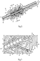
- rotor 30 may have a longitudinal central column 71, centered on longitudinal axis 31.
- a plurality of struts 63 connect between column 71 and inner heat exchange surface 38.
- Inlet runner 61 extends through central column 71, and coolant supply conduits 62 extend through struts 63.
- struts 63 are oriented so as to extend outwardly from central column 71 and axially advance toward second axial end 46.
- Another plurality of struts 65 are oriented so as to axially advance toward first axial end 42.
- each of struts 63 and 65 may have orientations so as to be oriented at about 45 degrees with respect to longitudinal axis 31.
- Struts 65 may be solid, whereas struts 63 may be hollow by virtue of conduits 62 therein.
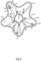
- Figure 4 there is shown a sectioned view taken along line 4-4 of Figure 2 . It can be seen that struts 63 and struts 65 extend into and out of the plane of the page, with features not visible in the section plane shown in phantom. It can also be seen that rotor body 31 has five lobes 35 alternating with five grooves 37. As suggested above, a greater or lesser number of lobes might be present in alternative designs. Also, while rotor 30 is depicted as a male rotor in other instances rotor 30 might have a female configuration.
- Coolant may be conveyed into coolant manifold 60 within rotor 30, and from manifold 60 to coolant supply conduits 62.
- Heat exchange surface 38 may be sprayed with coolant from conduits 62 at a plurality of axially and circumferentially distributed locations, so as to dissipate heat that is generated by the compression of the gas.
- the conveying and spraying may include conveying and spraying a refrigerant in liquid form that undergoes a phase change within rotor 30, which is then exhausted in gaseous form from rotor 30.
- the present disclosure is not limited as such, however, and other coolants and cooling schemes might be used.
- rotor 30 may experience axial thrust loads, bending loads, twisting loads and still others to varying degrees depending upon the specific design and the service environment. Such loads are commonly reacted via thrust and/or journal bearings, however, the rotor body itself can potentially be deflected during service and its constituent material can eventually experience some degree of material fatigue, potentially even ultimately leading to performance degradation or failure. In certain known rotor designs, for various reasons, among them commonly an abundance of material from which the rotor is made, a service life of the compressor system can be limited by factors other than material fatigue in the rotor. For that reason, the mechanical integrity of the rotor would not commonly be a limiting factor in the service life of the system. From the foregoing description, it will be understood that rotor 30 may be constructed with a relatively small amount of material, with rotor body 31 being relatively light in weight.
- struts 63 and 65 can serve to stiffen rotor body 31.
- struts 63 and 65 intersect, and can form an internal stiffening framework with material being placed where optimally necessary to manage the expected loads on the system.
- Another way to understand this principle is that with cooling more than adequately provided for structural considerations can predominantly drive the placement of material rather than cooling requirements.
- Alternative embodiments are contemplated where struts are provided that axially advance only in one direction, in other words the struts only run one way.
- struts could be oriented in helical patterns, either the same as or counter to the helical form of lobes 35 and grooves 37.
Landscapes
- Engineering & Computer Science (AREA)
- Mechanical Engineering (AREA)
- General Engineering & Computer Science (AREA)
- Applications Or Details Of Rotary Compressors (AREA)
- Structures Of Non-Positive Displacement Pumps (AREA)
Claims (11)
- Ein Rotor für ein Verdichtersystem, beinhaltend:einen Rotorkörper (39), der eine Längsachse (31) definiert, die sich zwischen einem ersten Axialende (42) des Körpers und einem zweiten Axialende (46) des Körpers erstreckt und eine äußere Verdichtungsoberfläche (36) aufweist, die strukturiert ist, um während der Drehung des Rotorkörpers (39) auf ein Gas aufzutreffen, das zwischen einem Gaseinlass (24) und einem Gasauslass (26) in einem Gehäuse (22) befördert wird;wobei der Rotorkörper (39) ferner eine innere Wärmeaustauschoberfläche (38) umfasst, die einen Kühlhohlraum (80) definiert und darin gebildet einen Kühlmitteleinlass (44), einen Kühlmittelauslass (48) in Fluidverbindung mit dem Kühlhohlraum (80) und einen Kühlmittelverteiler (60) aufweist; undwobei der Kühlmittelverteiler (60) Folgendes aufweist: einen Einlassverteilerkanal (61), der mit dem Kühlmitteleinlass (44) fluidisch verbunden ist, und eine Vielzahl von Kühlmittelzufuhrleitungen (62), die eine Axial- und eine Umfangsverteilung aufweisen und sich von dem Einlassverteilerkanal (61) nach außen erstrecken, um ein Kühlmittelfluid zu der inneren Wärmeaustauschoberfläche (38) zu leiten;wobei der Kühlhohlraum (80) strukturiert ist, um das Kühlmittelfluid, das aus der Vielzahl von Kühlmittelzufuhrleitungen (62) austritt, zu sammeln.
- Rotor gemäß Anspruch 1, wobei der Rotorkörper (39) ferner eine longitudinale zentrale Säule (71) umfasst, und eine Vielzahl von Streben (63), die zwischen der zentralen Säule (71) und der inneren Wärmeaustauschoberfläche (38) eine Verbindung bilden, und wobei sich der Einlassverteilerkanal (61) durch die zentrale Säule (71) erstreckt und sich die Vielzahl von Kühlmittelzufuhrleitungen (62) durch die Vielzahl von Streben (63) erstreckt.
- Rotor gemäß Anspruch 2, wobei die Vielzahl von Streben (63) ausgerichtet ist, um zu dem zweiten Axialende (46) des Körpers axial vorzudringen.
- Rotor gemäß Anspruch 3, wobei der Rotorkörper (39) ferner eine Vielzahl von weiteren Streben (65) umfasst, die zwischen der zentralen Säule (71) und der inneren Wärmeaustauschoberfläche (38) eine Verbindung bilden und ausgerichtet sind, um zu dem ersten Axialende (42) des Körpers axial vorzudringen, oder
wobei jede der Vielzahl von Streben (63) eine Sprühöffnung (90) umfasst, die die entsprechende Kühlmittelzufuhrleitung (65) mit dem Kühlhohlraum (80) fluidisch verbindet. - Rotor gemäß einem der Ansprüche 2 bis 4, wobei der Rotorkörper (39) einen Teilabschnitt in einem Stück umfasst, in dem sich die Streben (63) und/oder weiteren Streben (65) befinden.
- Rotor gemäß Anspruch 5, wobei der Rotorkörper (39) durchweg eine einheitliche Materialzusammensetzung aufweist; oderferner einen Schneckenrotor beinhaltet, wobei die äußere Verdichtungsoberfläche (36) eine Vielzahl von schraubenförmigen Flügeln (35) in einer abwechselnden Anordnung mit einer Vielzahl von schraubenförmigen Rillen (37) bildet, und wobei die innere Wärmeaustauscheroberfläche (38) eine Form aufweist, die komplementär zu der äußeren Verdichtungsoberfläche (36) ist; undwobei der Rotorkörper (39) insbesondere ferner einen Abflussringraum (72) umfasst, der den Kühlhohlraum (80) mit einem Abflussauslass fluidisch verbindet.
- Rotor gemäß einem der Ansprüche 2 bis 6, wobei die Vielzahl von Streben (63) insbesondere eine Axial- und eine Umfangsverteilung aufweist.
- Rotor gemäß Anspruch 4 oder den Ansprüchen 5 bis 7, wenn anhängig an Anspruch 4, wobei die weiteren Streben (65) massiv sind.
- Ein Verdichtersystem (10), das den Rotor gemäß einem vorhergehenden Anspruch beinhaltet.
- Verdichtersystem (10) gemäß Anspruch 9, wobei der Rotor ein Rotor gemäß einem der Ansprüche 2 bis 8 ist; und
wobei sich die zentrale Säule (71) axial durch den Kühlhohlraum (80) zwischen dem ersten Axialende (42) des Körpers und dem zweiten Axialende (46) des Körpers erstreckt. - Verdichtersystem (10) gemäß Anspruch 9, wobei der Rotor einen von einem Hauptrotor (30) und einem Nebenrotor (132) umfasst und ferner den anderen von einem Hauptrotor (30) und einem Nebenrotor (132) beinhaltet, der innerhalb des Gehäuses (22) drehbar ist und mit dem ersten Rotor ineinandergreift.
Applications Claiming Priority (1)
| Application Number | Priority Date | Filing Date | Title |
|---|---|---|---|
| US14/837,912 US10495090B2 (en) | 2015-08-27 | 2015-08-27 | Rotor for a compressor system having internal coolant manifold |
Publications (2)
| Publication Number | Publication Date |
|---|---|
| EP3135863A1 EP3135863A1 (de) | 2017-03-01 |
| EP3135863B1 true EP3135863B1 (de) | 2021-12-29 |
Family
ID=56888926
Family Applications (1)
| Application Number | Title | Priority Date | Filing Date |
|---|---|---|---|
| EP16185305.6A Active EP3135863B1 (de) | 2015-08-27 | 2016-08-23 | Rotor für ein verdichtersystem mit internem kühlmittelverteiler |
Country Status (3)
| Country | Link |
|---|---|
| US (1) | US10495090B2 (de) |
| EP (1) | EP3135863B1 (de) |
| CN (1) | CN106640641B (de) |
Families Citing this family (8)
| Publication number | Priority date | Publication date | Assignee | Title |
|---|---|---|---|---|
| JP6895585B2 (ja) * | 2018-03-30 | 2021-06-30 | 株式会社日立産機システム | スクリューロータ、流体機械本体及び流体機械 |
| CN109681430A (zh) * | 2018-12-25 | 2019-04-26 | 江阴爱尔姆真空设备有限公司 | 一种真空泵螺杆转子冷却装置 |
| EP3973189B1 (de) | 2019-05-20 | 2024-10-30 | Carrier Corporation | Kühlmittelschraubenverdichter mit direktantrieb mit flüssigkeitsgeschmierten rotoren |
| DE102020103384B4 (de) * | 2020-02-11 | 2025-11-13 | Gardner Denver Deutschland Gmbh | Schraubenverdichter mit einseitig gelagerten Rotoren |
| CN111594439A (zh) * | 2020-04-23 | 2020-08-28 | 浙江佳成机械有限公司 | 一种三级螺杆压缩机 |
| CN114483585B (zh) * | 2022-03-01 | 2024-08-06 | 德斯兰压缩机(上海)有限公司 | 一种螺杆转子及使用该螺杆转子的空压机 |
| US12385500B1 (en) | 2024-07-03 | 2025-08-12 | Hamilton Sundstrand Corporation | Addtively manufactured bi-metal integral shaft and motor rotor heat exchanger and tie rod for ram air fan |
| CN119308850B (zh) * | 2024-12-17 | 2025-03-25 | 德耐尔节能科技(上海)股份有限公司 | 一种具有冷却功能的空压机阳极转子 |
Family Cites Families (23)
| Publication number | Priority date | Publication date | Assignee | Title |
|---|---|---|---|---|
| US2325617A (en) | 1938-01-13 | 1943-08-03 | Jarvis C Marble | Rotor |
| BE481609A (de) | 1947-04-03 | |||
| GB690185A (en) | 1949-09-15 | 1953-04-15 | Ljungstroms Angturbin Ab | Improvements in or relating to the cooling of rotary compressors or motors |
| US2801792A (en) | 1949-09-15 | 1957-08-06 | Svenska Rotor Maskiner Ab | Cooling of machine structures |
| US2714314A (en) | 1951-05-15 | 1955-08-02 | Howden James & Co Ltd | Rotors for rotary gas compressors and motors |
| DE1021530B (de) | 1955-01-17 | 1957-12-27 | Leybolds Nachfolger E | Drehkolbengeblaese |
| US2918209A (en) | 1957-05-14 | 1959-12-22 | Schueller Otto | Motor-compressor unit |
| SE315444B (de) | 1965-05-14 | 1969-09-29 | A Lysholm | |
| GB1530898A (en) | 1974-10-29 | 1978-11-01 | Svenska Rotor Maskiner Ab | Rotary positive-displacement internal-combustion engine |
| US5772418A (en) | 1995-04-07 | 1998-06-30 | Tochigi Fuji Sangyo Kabushiki Kaisha | Screw type compressor rotor, rotor casting core and method of manufacturing the rotor |
| US6045343A (en) | 1998-01-15 | 2000-04-04 | Sunny King Machinery Co., Ltd. | Internally cooling rotary compression equipment |
| EP1026399A1 (de) | 1999-02-08 | 2000-08-09 | Ateliers Busch S.A. | Zwillings-Förderschrauben |
| DE19963172A1 (de) | 1999-12-27 | 2001-06-28 | Leybold Vakuum Gmbh | Schraubenpumpe mit einem Kühlmittelkreislauf |
| GB0419514D0 (en) * | 2004-09-02 | 2004-10-06 | Boc Group Plc | Cooling of pump rotors |
| EP1784576B2 (de) | 2004-09-02 | 2016-01-13 | Edwards Limited | Kühlen von pumprotoren |
| JP2007170341A (ja) * | 2005-12-26 | 2007-07-05 | Toyota Industries Corp | スクリュー式流体機械 |
| US7793516B2 (en) | 2006-09-29 | 2010-09-14 | Lenovo (Singapore) Pte. Ltd. | Rotary compressor with fluidic passages in rotor |
| BE1017371A3 (nl) * | 2006-11-23 | 2008-07-01 | Atlas Copco Airpower Nv | Rotor en compressorelement voorzien van zulke rotor. |
| US7993118B2 (en) | 2007-06-26 | 2011-08-09 | GM Global Technology Operations LLC | Liquid-cooled rotor assembly for a supercharger |
| BE1018583A3 (de) * | 2009-06-10 | 2011-04-05 | Atlas Copco Airpower Nv | |
| CN102242711B (zh) | 2011-07-05 | 2014-01-01 | 山东省临风鼓风机有限公司 | 耐高温、高压力升型罗茨鼓风机 |
| US11359632B2 (en) | 2014-10-31 | 2022-06-14 | Ingersoll-Rand Industrial U.S., Inc. | Rotary screw compressor rotor having work extraction mechanism |
| US9683569B2 (en) * | 2015-08-27 | 2017-06-20 | Ingersoll-Rand Company | Compressor system having rotor with distributed coolant conduits and method |
-
2015
- 2015-08-27 US US14/837,912 patent/US10495090B2/en active Active
-
2016
- 2016-08-23 EP EP16185305.6A patent/EP3135863B1/de active Active
- 2016-08-26 CN CN201610730742.9A patent/CN106640641B/zh active Active
Also Published As
| Publication number | Publication date |
|---|---|
| US20170058901A1 (en) | 2017-03-02 |
| US10495090B2 (en) | 2019-12-03 |
| CN106640641B (zh) | 2020-09-11 |
| EP3135863A1 (de) | 2017-03-01 |
| CN106640641A (zh) | 2017-05-10 |
Similar Documents
| Publication | Publication Date | Title |
|---|---|---|
| EP3135863B1 (de) | Rotor für ein verdichtersystem mit internem kühlmittelverteiler | |
| EP3135862B1 (de) | Verdichteranlage mit einem rotor mit verteilten kühlleitungen und verfahren | |
| EP2665936B2 (de) | Pumpe mit einer statoranordnung mit einem ersten teil und einem zweiten teil | |
| KR20130064724A (ko) | 로터리 압축-팽창기 시스템 및 사용 및 제조 관련 방법 | |
| US20180023567A1 (en) | Rotary compressor | |
| US20240191714A1 (en) | Element, device and method for compressing gas to be compressed having a low temperature | |
| EP3043071B1 (de) | Flüssigkeitspumpe und rankine-kreislaufvorrichtung | |
| US7963744B2 (en) | Cooling of pump rotors | |
| JP3250957U (ja) | 改良されたオイルインジェクタを備える圧縮機要素 | |
| US20230031560A1 (en) | Rotating machine and refrigeration device using same | |
| US20250207605A1 (en) | Turbomachine and apparatus comprising said turbomachine | |
| US10718334B2 (en) | Compressor with ribbed cooling jacket | |
| WO2004059130A1 (ja) | 回転流体機械 | |
| US20250305497A1 (en) | Machine for expanding or compressing compressible media | |
| EP4628730A1 (de) | Schraubenverdichter | |
| US11920486B2 (en) | High-temperature component and method of producing the high-temperature component | |
| WO2025127936A1 (en) | A machine of positive displacement, centric reciprocating type with a pressure sealing system and method | |
| JP2006200383A (ja) | エジェクタ及び流体の圧縮方法、冷熱生成システム並びに真空ポンプシステム |
Legal Events
| Date | Code | Title | Description |
|---|---|---|---|
| PUAI | Public reference made under article 153(3) epc to a published international application that has entered the european phase |
Free format text: ORIGINAL CODE: 0009012 |
|
| STAA | Information on the status of an ep patent application or granted ep patent |
Free format text: STATUS: REQUEST FOR EXAMINATION WAS MADE |
|
| 17P | Request for examination filed |
Effective date: 20160823 |
|
| AK | Designated contracting states |
Kind code of ref document: A1 Designated state(s): AL AT BE BG CH CY CZ DE DK EE ES FI FR GB GR HR HU IE IS IT LI LT LU LV MC MK MT NL NO PL PT RO RS SE SI SK SM TR |
|
| AX | Request for extension of the european patent |
Extension state: BA ME |
|
| RAP1 | Party data changed (applicant data changed or rights of an application transferred) |
Owner name: INGERSOLL-RAND INDUSTRIAL U.S., INC. |
|
| STAA | Information on the status of an ep patent application or granted ep patent |
Free format text: STATUS: EXAMINATION IS IN PROGRESS |
|
| 17Q | First examination report despatched |
Effective date: 20210322 |
|
| GRAP | Despatch of communication of intention to grant a patent |
Free format text: ORIGINAL CODE: EPIDOSNIGR1 |
|
| STAA | Information on the status of an ep patent application or granted ep patent |
Free format text: STATUS: GRANT OF PATENT IS INTENDED |
|
| INTG | Intention to grant announced |
Effective date: 20210914 |
|
| GRAS | Grant fee paid |
Free format text: ORIGINAL CODE: EPIDOSNIGR3 |
|
| GRAA | (expected) grant |
Free format text: ORIGINAL CODE: 0009210 |
|
| STAA | Information on the status of an ep patent application or granted ep patent |
Free format text: STATUS: THE PATENT HAS BEEN GRANTED |
|
| AK | Designated contracting states |
Kind code of ref document: B1 Designated state(s): AL AT BE BG CH CY CZ DE DK EE ES FI FR GB GR HR HU IE IS IT LI LT LU LV MC MK MT NL NO PL PT RO RS SE SI SK SM TR |
|
| REG | Reference to a national code |
Ref country code: GB Ref legal event code: FG4D |
|
| REG | Reference to a national code |
Ref country code: CH Ref legal event code: EP |
|
| REG | Reference to a national code |
Ref country code: AT Ref legal event code: REF Ref document number: 1458802 Country of ref document: AT Kind code of ref document: T Effective date: 20220115 |
|
| REG | Reference to a national code |
Ref country code: IE Ref legal event code: FG4D |
|
| REG | Reference to a national code |
Ref country code: DE Ref legal event code: R096 Ref document number: 602016067764 Country of ref document: DE |
|
| REG | Reference to a national code |
Ref country code: LT Ref legal event code: MG9D |
|
| PG25 | Lapsed in a contracting state [announced via postgrant information from national office to epo] |
Ref country code: RS Free format text: LAPSE BECAUSE OF FAILURE TO SUBMIT A TRANSLATION OF THE DESCRIPTION OR TO PAY THE FEE WITHIN THE PRESCRIBED TIME-LIMIT Effective date: 20211229 Ref country code: LT Free format text: LAPSE BECAUSE OF FAILURE TO SUBMIT A TRANSLATION OF THE DESCRIPTION OR TO PAY THE FEE WITHIN THE PRESCRIBED TIME-LIMIT Effective date: 20211229 Ref country code: FI Free format text: LAPSE BECAUSE OF FAILURE TO SUBMIT A TRANSLATION OF THE DESCRIPTION OR TO PAY THE FEE WITHIN THE PRESCRIBED TIME-LIMIT Effective date: 20211229 Ref country code: BG Free format text: LAPSE BECAUSE OF FAILURE TO SUBMIT A TRANSLATION OF THE DESCRIPTION OR TO PAY THE FEE WITHIN THE PRESCRIBED TIME-LIMIT Effective date: 20220329 |
|
| REG | Reference to a national code |
Ref country code: NL Ref legal event code: MP Effective date: 20211229 |
|
| REG | Reference to a national code |
Ref country code: AT Ref legal event code: MK05 Ref document number: 1458802 Country of ref document: AT Kind code of ref document: T Effective date: 20211229 |
|
| PG25 | Lapsed in a contracting state [announced via postgrant information from national office to epo] |
Ref country code: SE Free format text: LAPSE BECAUSE OF FAILURE TO SUBMIT A TRANSLATION OF THE DESCRIPTION OR TO PAY THE FEE WITHIN THE PRESCRIBED TIME-LIMIT Effective date: 20211229 Ref country code: NO Free format text: LAPSE BECAUSE OF FAILURE TO SUBMIT A TRANSLATION OF THE DESCRIPTION OR TO PAY THE FEE WITHIN THE PRESCRIBED TIME-LIMIT Effective date: 20220329 Ref country code: LV Free format text: LAPSE BECAUSE OF FAILURE TO SUBMIT A TRANSLATION OF THE DESCRIPTION OR TO PAY THE FEE WITHIN THE PRESCRIBED TIME-LIMIT Effective date: 20211229 Ref country code: HR Free format text: LAPSE BECAUSE OF FAILURE TO SUBMIT A TRANSLATION OF THE DESCRIPTION OR TO PAY THE FEE WITHIN THE PRESCRIBED TIME-LIMIT Effective date: 20211229 Ref country code: GR Free format text: LAPSE BECAUSE OF FAILURE TO SUBMIT A TRANSLATION OF THE DESCRIPTION OR TO PAY THE FEE WITHIN THE PRESCRIBED TIME-LIMIT Effective date: 20220330 |
|
| PG25 | Lapsed in a contracting state [announced via postgrant information from national office to epo] |
Ref country code: NL Free format text: LAPSE BECAUSE OF FAILURE TO SUBMIT A TRANSLATION OF THE DESCRIPTION OR TO PAY THE FEE WITHIN THE PRESCRIBED TIME-LIMIT Effective date: 20211229 |
|
| PG25 | Lapsed in a contracting state [announced via postgrant information from national office to epo] |
Ref country code: SM Free format text: LAPSE BECAUSE OF FAILURE TO SUBMIT A TRANSLATION OF THE DESCRIPTION OR TO PAY THE FEE WITHIN THE PRESCRIBED TIME-LIMIT Effective date: 20211229 Ref country code: SK Free format text: LAPSE BECAUSE OF FAILURE TO SUBMIT A TRANSLATION OF THE DESCRIPTION OR TO PAY THE FEE WITHIN THE PRESCRIBED TIME-LIMIT Effective date: 20211229 Ref country code: RO Free format text: LAPSE BECAUSE OF FAILURE TO SUBMIT A TRANSLATION OF THE DESCRIPTION OR TO PAY THE FEE WITHIN THE PRESCRIBED TIME-LIMIT Effective date: 20211229 Ref country code: PT Free format text: LAPSE BECAUSE OF FAILURE TO SUBMIT A TRANSLATION OF THE DESCRIPTION OR TO PAY THE FEE WITHIN THE PRESCRIBED TIME-LIMIT Effective date: 20220429 Ref country code: ES Free format text: LAPSE BECAUSE OF FAILURE TO SUBMIT A TRANSLATION OF THE DESCRIPTION OR TO PAY THE FEE WITHIN THE PRESCRIBED TIME-LIMIT Effective date: 20211229 Ref country code: EE Free format text: LAPSE BECAUSE OF FAILURE TO SUBMIT A TRANSLATION OF THE DESCRIPTION OR TO PAY THE FEE WITHIN THE PRESCRIBED TIME-LIMIT Effective date: 20211229 Ref country code: CZ Free format text: LAPSE BECAUSE OF FAILURE TO SUBMIT A TRANSLATION OF THE DESCRIPTION OR TO PAY THE FEE WITHIN THE PRESCRIBED TIME-LIMIT Effective date: 20211229 |
|
| PG25 | Lapsed in a contracting state [announced via postgrant information from national office to epo] |
Ref country code: PL Free format text: LAPSE BECAUSE OF FAILURE TO SUBMIT A TRANSLATION OF THE DESCRIPTION OR TO PAY THE FEE WITHIN THE PRESCRIBED TIME-LIMIT Effective date: 20211229 Ref country code: AT Free format text: LAPSE BECAUSE OF FAILURE TO SUBMIT A TRANSLATION OF THE DESCRIPTION OR TO PAY THE FEE WITHIN THE PRESCRIBED TIME-LIMIT Effective date: 20211229 |
|
| PG25 | Lapsed in a contracting state [announced via postgrant information from national office to epo] |
Ref country code: IS Free format text: LAPSE BECAUSE OF FAILURE TO SUBMIT A TRANSLATION OF THE DESCRIPTION OR TO PAY THE FEE WITHIN THE PRESCRIBED TIME-LIMIT Effective date: 20220429 |
|
| REG | Reference to a national code |
Ref country code: DE Ref legal event code: R097 Ref document number: 602016067764 Country of ref document: DE |
|
| PG25 | Lapsed in a contracting state [announced via postgrant information from national office to epo] |
Ref country code: DK Free format text: LAPSE BECAUSE OF FAILURE TO SUBMIT A TRANSLATION OF THE DESCRIPTION OR TO PAY THE FEE WITHIN THE PRESCRIBED TIME-LIMIT Effective date: 20211229 Ref country code: AL Free format text: LAPSE BECAUSE OF FAILURE TO SUBMIT A TRANSLATION OF THE DESCRIPTION OR TO PAY THE FEE WITHIN THE PRESCRIBED TIME-LIMIT Effective date: 20211229 |
|
| PLBE | No opposition filed within time limit |
Free format text: ORIGINAL CODE: 0009261 |
|
| STAA | Information on the status of an ep patent application or granted ep patent |
Free format text: STATUS: NO OPPOSITION FILED WITHIN TIME LIMIT |
|
| 26N | No opposition filed |
Effective date: 20220930 |
|
| PG25 | Lapsed in a contracting state [announced via postgrant information from national office to epo] |
Ref country code: SI Free format text: LAPSE BECAUSE OF FAILURE TO SUBMIT A TRANSLATION OF THE DESCRIPTION OR TO PAY THE FEE WITHIN THE PRESCRIBED TIME-LIMIT Effective date: 20211229 |
|
| PG25 | Lapsed in a contracting state [announced via postgrant information from national office to epo] |
Ref country code: MC Free format text: LAPSE BECAUSE OF FAILURE TO SUBMIT A TRANSLATION OF THE DESCRIPTION OR TO PAY THE FEE WITHIN THE PRESCRIBED TIME-LIMIT Effective date: 20211229 |
|
| REG | Reference to a national code |
Ref country code: CH Ref legal event code: PL |
|
| PG25 | Lapsed in a contracting state [announced via postgrant information from national office to epo] |
Ref country code: LU Free format text: LAPSE BECAUSE OF NON-PAYMENT OF DUE FEES Effective date: 20220823 Ref country code: LI Free format text: LAPSE BECAUSE OF NON-PAYMENT OF DUE FEES Effective date: 20220831 Ref country code: CH Free format text: LAPSE BECAUSE OF NON-PAYMENT OF DUE FEES Effective date: 20220831 |
|
| REG | Reference to a national code |
Ref country code: BE Ref legal event code: MM Effective date: 20220831 |
|
| P01 | Opt-out of the competence of the unified patent court (upc) registered |
Effective date: 20230523 |
|
| PG25 | Lapsed in a contracting state [announced via postgrant information from national office to epo] |
Ref country code: IE Free format text: LAPSE BECAUSE OF NON-PAYMENT OF DUE FEES Effective date: 20220823 |
|
| PG25 | Lapsed in a contracting state [announced via postgrant information from national office to epo] |
Ref country code: BE Free format text: LAPSE BECAUSE OF NON-PAYMENT OF DUE FEES Effective date: 20220831 |
|
| PG25 | Lapsed in a contracting state [announced via postgrant information from national office to epo] |
Ref country code: HU Free format text: LAPSE BECAUSE OF FAILURE TO SUBMIT A TRANSLATION OF THE DESCRIPTION OR TO PAY THE FEE WITHIN THE PRESCRIBED TIME-LIMIT; INVALID AB INITIO Effective date: 20160823 |
|
| PG25 | Lapsed in a contracting state [announced via postgrant information from national office to epo] |
Ref country code: CY Free format text: LAPSE BECAUSE OF FAILURE TO SUBMIT A TRANSLATION OF THE DESCRIPTION OR TO PAY THE FEE WITHIN THE PRESCRIBED TIME-LIMIT Effective date: 20211229 |
|
| PG25 | Lapsed in a contracting state [announced via postgrant information from national office to epo] |
Ref country code: MK Free format text: LAPSE BECAUSE OF FAILURE TO SUBMIT A TRANSLATION OF THE DESCRIPTION OR TO PAY THE FEE WITHIN THE PRESCRIBED TIME-LIMIT Effective date: 20211229 |
|
| PG25 | Lapsed in a contracting state [announced via postgrant information from national office to epo] |
Ref country code: MT Free format text: LAPSE BECAUSE OF FAILURE TO SUBMIT A TRANSLATION OF THE DESCRIPTION OR TO PAY THE FEE WITHIN THE PRESCRIBED TIME-LIMIT Effective date: 20211229 |
|
| PGFP | Annual fee paid to national office [announced via postgrant information from national office to epo] |
Ref country code: DE Payment date: 20250828 Year of fee payment: 10 |
|
| PGFP | Annual fee paid to national office [announced via postgrant information from national office to epo] |
Ref country code: IT Payment date: 20250826 Year of fee payment: 10 |
|
| PGFP | Annual fee paid to national office [announced via postgrant information from national office to epo] |
Ref country code: GB Payment date: 20250829 Year of fee payment: 10 |
|
| PGFP | Annual fee paid to national office [announced via postgrant information from national office to epo] |
Ref country code: FR Payment date: 20250828 Year of fee payment: 10 |
|
| PG25 | Lapsed in a contracting state [announced via postgrant information from national office to epo] |
Ref country code: TR Free format text: LAPSE BECAUSE OF FAILURE TO SUBMIT A TRANSLATION OF THE DESCRIPTION OR TO PAY THE FEE WITHIN THE PRESCRIBED TIME-LIMIT Effective date: 20211229 |