EP3135578A1 - Structure de bord d'attaque pour aéronef, aile pour aéronef et aéronef - Google Patents
Structure de bord d'attaque pour aéronef, aile pour aéronef et aéronef Download PDFInfo
- Publication number
- EP3135578A1 EP3135578A1 EP16184482.4A EP16184482A EP3135578A1 EP 3135578 A1 EP3135578 A1 EP 3135578A1 EP 16184482 A EP16184482 A EP 16184482A EP 3135578 A1 EP3135578 A1 EP 3135578A1
- Authority
- EP
- European Patent Office
- Prior art keywords
- ribs
- leading
- skin
- edge structure
- aircraft
- Prior art date
- Legal status (The legal status is an assumption and is not a legal conclusion. Google has not performed a legal analysis and makes no representation as to the accuracy of the status listed.)
- Granted
Links
- 239000004033 plastic Substances 0.000 description 11
- 229920003023 plastic Polymers 0.000 description 11
- 230000000694 effects Effects 0.000 description 8
- 238000010521 absorption reaction Methods 0.000 description 5
- 238000004519 manufacturing process Methods 0.000 description 5
- 238000010586 diagram Methods 0.000 description 4
- 229910000838 Al alloy Inorganic materials 0.000 description 3
- 230000008878 coupling Effects 0.000 description 3
- 238000010168 coupling process Methods 0.000 description 3
- 238000005859 coupling reaction Methods 0.000 description 3
- 230000003247 decreasing effect Effects 0.000 description 2
- 239000000463 material Substances 0.000 description 2
- 238000004088 simulation Methods 0.000 description 2
- 229920002430 Fibre-reinforced plastic Polymers 0.000 description 1
- 239000004918 carbon fiber reinforced polymer Substances 0.000 description 1
- 239000011151 fibre-reinforced plastic Substances 0.000 description 1
- 239000000446 fuel Substances 0.000 description 1
- 238000005304 joining Methods 0.000 description 1
- 238000012423 maintenance Methods 0.000 description 1
- 239000007769 metal material Substances 0.000 description 1
- 238000000034 method Methods 0.000 description 1
- 238000003756 stirring Methods 0.000 description 1
- 238000003466 welding Methods 0.000 description 1
Images


Classifications
-
- B—PERFORMING OPERATIONS; TRANSPORTING
- B64—AIRCRAFT; AVIATION; COSMONAUTICS
- B64C—AEROPLANES; HELICOPTERS
- B64C3/00—Wings
- B64C3/28—Leading or trailing edges attached to primary structures, e.g. forming fixed slots
-
- B—PERFORMING OPERATIONS; TRANSPORTING
- B64—AIRCRAFT; AVIATION; COSMONAUTICS
- B64C—AEROPLANES; HELICOPTERS
- B64C3/00—Wings
- B64C3/18—Spars; Ribs; Stringers
- B64C3/185—Spars
-
- B—PERFORMING OPERATIONS; TRANSPORTING
- B64—AIRCRAFT; AVIATION; COSMONAUTICS
- B64C—AEROPLANES; HELICOPTERS
- B64C3/00—Wings
- B64C3/18—Spars; Ribs; Stringers
- B64C3/187—Ribs
-
- B—PERFORMING OPERATIONS; TRANSPORTING
- B64—AIRCRAFT; AVIATION; COSMONAUTICS
- B64C—AEROPLANES; HELICOPTERS
- B64C3/00—Wings
- B64C3/26—Construction, shape, or attachment of separate skins, e.g. panels
Definitions
- the present invention relates to a leading-edge structure for an aircraft, in particular, to a leading-edge structure that is capable of reducing an impact when colliding with a bird.
- an aircraft may collide with an airborne object such as a bird or a piece of ice, and thus its airframe is designed and fabricated so as to withstand even a collision with an airborne object.
- an airborne object such as a bird or a piece of ice
- its airframe is designed and fabricated so as to withstand even a collision with an airborne object.
- increasing the strength of the airframe leads to an increase in weight of the airframe. Therefore, an unreasonable increasing of the strength is not allowed.
- JP 2007-532397 A1 proposes absorbing kinetic energy caused by a collision with a bird by means of plastic deformation of a stringer over a considerable length.
- the stringer is disposed being brought into contact with a plurality of ribs so as to support an outer skin.
- WO 2013/27388 A1 proposes that, out of a plurality of rib members disposed in the longitudinal direction of a slat at intervals, a pair of rib members are coupled by a coupling member, typically a wire cable. According to WO 2013/27388 A1 , a slat is prevented from being broken into pieces between a pair of rib members even when a bird collides with the slat during flight of an aircraft, and the slat suffers such damage that not only a skin but also a rib member of the slat deforms.
- forward and “rearward” are defined on the basis of the direction in which the aircraft flies.
- JP 2007-532397 A1 is only to dispose stringers so as to be brought into contact with a plurality of ribs for an effective absorption of energy. Thus, it is possible to minimize an increase in weight. However, considering fuel efficiency of an aircraft, it is desirable that the weight is not increased but preferably reduced. Also in WO 2013/27388 A1 , since the pair of rib members are coupled by a coupling member, the weight is increased by at least the coupling member.
- the present invention has an objective to provide a leading-edge structure for an aircraft that is capable of, in the case of a collision with an airborne object, effectively absorbing the energy of the collision with the airborne object while its weight is not increased but preferably reduced.
- the present invention is a leading-edge structure for an aircraft that constitutes any leading-edge portion in the airframe of the aircraft, and includes a spar that extends in a predetermined direction, a plurality of ribs that are provided in the predetermined direction of the spar at intervals, and a skin that is supported by the plurality of ribs, wherein among the plurality of ribs, one or more of the ribs have a front end that is provided with a gap with the skin.
- a leading-edge structure for an aircraft attention is paid to a maximum utilization of plastic deformation of a skin to absorb the energy of a collision with an airborne object. That is, as described in JP 2007-532397 A1 and WO 2013/27388 A1 , in a conventional leading-edge structure, since all ribs contact and support a skin also at their front ends, it is considered that the skin is supported at both ends by a pair of adjacent ribs. Moreover, the skin is fixed by fasteners at portions corresponding to the front ends of the ribs and the other portions.
- ribs are disposed as many as needed for stiffening that is originally intended, ribs each having a front end provided with gaps with a skin are selectively provided, so as to eliminate fasteners that may be a start point of a rupture of the skin as well as to increase the span L substantially.
- This enables, in the case of a collision with an airborne object, securing the amount of plastic deformation of the skin, increasing the amount of energy absorption.
- the selectively provided ribs support the skin except for ranges other than their front ends, the selectively provided ribs can serve the original purpose of stiffening the skin.
- the leading-edge structure includes a pair of first ribs and a plurality of second ribs, the pair of first ribs being disposed with a predetermined interval, the plurality of second ribs disposed between the pair of first ribs, and gaps are provided between the front ends of the second ribs and the skin.
- the front ends of the plurality of second ribs disposed between the pair of first ribs are provided with the gaps with the skin. Therefore, assuming that the ribs are disposed at regular intervals of the span L, the skin can perform plastic deformation corresponding to at least 3L. Therefore, it is possible to increase the amount of energy absorption.
- the pair of first ribs have a stiffness higher than that of the second ribs.
- the first ribs support the skin also with their front ends. Therefore, by having a stiffness higher than that of the second ribs accordingly, the first ribs fulfill the purpose of stiffening the skin.
- the pair of first ribs are fixed to the spar, but the second ribs are not fixed to the spar.
- the second ribs can be detached collectively together with the skin when a leading-edge structure is detached in a maintenance check.
- the second ribs can serve the purpose of stiffening the skin although not being fixed to the spar as long as the second ribs support the skin at portions other than those corresponding to their front ends.
- the present invention provides a wing of an aircraft including the leading-edge structure described above and a wing body that is connected to this leading-edge structure.
- This wing is applied to at least one of a main wing, a horizontal tail, and a vertical tail.
- the present invention provides an aircraft including the above wing.
- leading-edge structure in the case of a collision with an airborne object, it is possible to absorb effectively the energy of the collision with the airborne object by increasing the amount of plastic deformation of the skin. Moreover, according to the present invention, an increase in weight does not occur. Moreover, it is possible in manufacture to obviate an operation of attaching fasteners at the front ends of ribs, which is time-consuming, also enabling the reduction in a production time of a leading-edge structure.
- the present embodiment describes an example in which a leading-edge structure according to the present invention is applied to a vertical tail 3 of an aircraft 1 illustrated in FIG. 7 .
- the vertical tail 3 includes a leading-edge structure 10 that is oriented toward the front of the aircraft 1.
- the purpose of providing the leading-edge structure 10 is to prevent the breakage of a wing body 4 of the vertical tail 3 that is provided being connected rearward from the leading-edge structure 10, even in the case of a collision with an airborne object, for example, a bird.
- the leading-edge structure 10 in the present embodiment prevents the breakage of the wing body 4 without increasing its weight.
- leading-edge structure 10 The structure of the leading-edge structure 10 will be described below, followed by the description of effects exerted by the structure. It is noted that, in the present embodiment, “forward” and “rearward” are defined on the basis of a direction in which the aircraft 1 flies.
- the leading-edge structure 10 includes, as illustrated in FIG. 1 , a spar 11 that serves as a boundary with the wing body 4, a plurality of ribs (first ribs 14, second ribs 15) that are disposed in the longitudinal direction of the spar 11 at predetermined intervals, and a skin 17 that constitutes an outer shell of the leading-edge structure 10.
- the spar 11, the ribs (first ribs 14, second rib 15), and the skin 17 constituting the leading-edge structure 10 are manufactured with a structural material, preferably a metallic material such as an aluminum alloy having a high specific strength, and a fiber reinforced plastic such as a carbon fiber reinforced plastic.
- the spar 11 is provided in such a manner as to extend in a predetermined direction, exists at a boundary between the leading-edge structure 10 and the wing body 4, and constitutes a part of the wing body 4 on its front-end side.
- the spar 11 can be formed by joining plate-shaped structural materials together.
- the present embodiment is adapted to minimize the breakage of the spar 11 even by an impact of a collision of an airborne object with the leading-edge structure 10.
- ribs 13 in the present embodiment including two kinds of stiffening members, the first ribs 14 and the second ribs 15, support the skin 17.
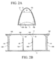
- the first rib 14 includes, as illustrated in FIG. 1 and FIG. 2A , a rib body 14A that has a spindle-like planar shape extending from a rear end (the lower end of FIG. 2B ) to a front end (the upper end of FIG. 2B ), and on the circumference of the rib body 14A, flanges 14B that project on both sides in the thickness direction of the rib body 14A.
- the rear end of the rib body 14A is fixed to the spar 11, and the flanges 14B fix and support the skin 17 with their entire regions from the rear end to the front end.
- the support of the skin 17 is made by causing a plurality of fasteners (not illustrated) to penetrate from the outside of the skin 17 to the flange 14B so as to fix the skin 17.
- the fasteners are provided at predetermined intervals in the circumferential direction of the flanges 14B.
- first ribs 14 There are the plurality of first ribs 14 provided at the predetermined intervals, and between adjacent first ribs 14, a plurality of second ribs 15 are provided. Therefore, the interval between adjacent first ribs 14 is set to be significantly wider than the interval between adjacent second ribs 15.
- the first ribs 14 are manufactured to have a high stiffness as compared with the second ribs 15. This enables the skin 17 to be reliably supported to the spar 11.
- the second rib 15 also includes, as illustrated in FIG. 1 and FIG. 2B , a rib body 15A, and on the circumference of the rib body 15A, flanges 15B that project on both sides in the thickness direction of the rib body 15A.
- the basic configuration of the second rib 15 having the rib body 15A and the flanges 15B is common to that of the first rib 14, but the planar shape of the rib body 15A is different from that of the rib body 14A. That is, the rib body 15A has a spindle shape similar to that of the rib body 15A up to some extent from the rear end to the front end and have a curvature, but as compared with the rib body 14A, the rib body 15A lacks a portion from the extent, having a front end 15C that forms a straight line.
- the rear-end side of the rib body 15A is not fixed but only brought into contact with the spar 11, and the flanges 15B supports the skin 17 with their entire regions.
- the support of the skin 17 is made by, as with the first rib 14, a plurality of fasteners.
- the front end 15C is linear, and the flange 15B is made to have a dimension in a front-rear direction short as compared with the first rib 14, a gap is provided between the front end 15C and the skin 17. This gap functions as a receiving space 18 that allows the skin 17 to deform rearward.
- the plurality of second ribs 15 in the present embodiment have the same configuration, and the receiving space 18 is provided in every second rib 15 between its front end 15C and the skin 17. Therefore, the front-end portion of the skin 17 can be considered to be supported at both ends by adjacent first ribs 14.
- the skin 17 has, as illustrated in FIG. 1 and FIG. 2A , a crosscut that is spindle-shaped, and is made to cover the first ribs 14 and the second ribs 15 from the forward side, forming the outer shell of the leading-edge structure 10.
- the skin 17 is fixed to the first ribs 14 and the second ribs 15 by fasteners (not illustrated), being supported by the first ribs 14 and the second ribs 15.
- the fasteners are disposed at the predetermined intervals from the front end to the rear end of each of the first ribs 14 and the second ribs 15.
- a span between adjacent first ribs 14 is set to be long, and between the first ribs 14, the receiving spaces 18 are provided forward of the front ends 15C of the second ribs 15. Therefore, when the skin 17 receives an external rearward force between the adjacent first ribs 14, the skin 17 can receive this external force over the long span between the adjacent first ribs 14, performing plastic deformation, until the skin 17 bends to touch a second rib 15. This suggests that the support structure of the skin 17 in the present embodiment can absorb more kinetic energy of the external force. This will be described with reference to FIGS. 3A-3D and FIGS.
- FIGS. 3A-3D correspond to the present embodiment, in which a second rib 15 is provided adjacent to a first rib 14.
- the skin 17 bends.
- the front end 15C of the second rib 15 is positioned rearward of the skin 17, and thus accordingly, the skin 17 can bend more.
- the skin 17 is ruptured at a spot of the first rib 14, and this rupture occurs at a spot where the skin 17 is fixed to the first rib 14 by a fastener (not illustrated).
- the spot where the fastener penetrates is equivalent to a portion in the skin 17 where a cut-out is formed, having a small strength, and thus suffers a rupture earlier than the other portions.
- the skin 17 is brought into contact with the second rib 15 as illustrated in FIG. 3C .
- the second rib 15 deforms to be broken.
- the skin 17 is fixed to the flange 15B by the fastener except for a spot corresponding to the receiving space 18, the skin 17 suffers a rupture at a spot corresponding to the second rib 15.
- FIGS. 4A-4D how the skin 17 bends or suffers a rupture is basically the same as in the present embodiment.
- the skin 17 is supported by the third rib 16 from the outset, and as illustrated in FIG. 4B , the skin 17 bends only between the first rib 14 and the third rib 16, which in turn causes plastic deformation of the skin 17 to absorb a small amount of the kinetic energy of the bird B.
- a rupture of the skin 17 starts in an early stage of the collision, from a fastener at the front end of the third rib 16 as a start point. Therefore, as illustrated in FIG. 4C , the skin 17 suffers a rupture at the spot of the third rib 16 in an early stage. Since there is a significant portion of the kinetic energy of the bird B left, the bird B not only makes the third rib 16 deform but also, as illustrated in FIG. 4D , breaks the spar 11.
- the span between the pair of first ribs 14, by which the skin 17 is supported at both ends is short in the conventional example than in the present embodiment.
- more energy is absorbed by the skin 17 with the plastic deformation. Therefore, in the conventional example, the energy of the bird B cannot be absorbed totally only by the deformation of the skin 17 and the third rib 16, and as illustrated in FIG. 4D , the bird B may collide with and break even the spar 11.
- the energy of the bird B can be absorbed by the deformation of the skin 17 and the second rib 15, and thus as illustrated in FIG. 3D , it is possible to prevent the bird B from breaking the spar 11.
- FIGS. 5A and 5B illustrate the results of simulations to confirm effects of the present embodiment.
- FIG. 5A illustrates the result of the case where an airborne object (bird B) collides between a first rib 14 and a second rib 15 adjacent to each other
- FIG. 5B illustrates the result of the case where an airborne object collides between a second rib 15 and a second rib 15 adjacent to each other. From these results, the effects of the present embodiment can be confirmed.
- the mechanism for absorbing energy in the present embodiment needs no addition of a special and unprecedented member, and in addition, the second ribs 15 have a shape made by removing a front-end side from a conventional rib, allowing the reduction of their weights accordingly.
- the description is made as the front-end side is "removed" from the conventional rib, but in an actual manufacture of a second rib 15, the second ribs 15 can be manufactured to have a linear front end 15C in its original state. Thus, there is no additional step in manufacturing the second ribs 15.
- the linear shape of the front end 15C of the second rib 15 is merely an example, and the shape is optional as long as a receiving space 18 is provided between the second rib 15 and the skin 17 in the vicinity of the front end.
- shapes illustrated in FIG. 6A and FIG. 6B can be employed.
- the deformation amount of the skin 17 can be increased with an increase in the receiving space 18, namely, a gap between the front end 15C of the second rib 15 and the skin 17.
- a gap between the front end 15C of the second rib 15 and the skin 17.
- the consideration of the above facts helps determine the length of the gap between the front end 15C of the second rib 15 and the skin 17.
- the embodiment previously described has been made about the example including the pair of first ribs 14, 14 that have a relatively high stiffness and including therebetween the plurality of second ribs 15 that have a relatively low stiffness.
- the present invention is assumed to have a plurality of ribs, and as long as the plurality of ribs include one or more ribs each including a front end provided with a gap with the skin, the effect of the present invention of increasing the amount of plastic deformation of the skin can be exerted.
- the structure and arrangement of the ribs are optional, and for example, as illustrated in FIG. 6C , a fourth rib 19 can be provided midway between the pair of first ribs 14, 14, the fourth rib 19 having a relatively low stiffness and supporting the skin 17 up to its front end.
- the present invention allows the provision of a stiffening plate 20 for increasing the stiffness of the skin 17, in the gap between the second ribs 15 and the skin 17.
- a stiffening plate 20 for increasing the stiffness of the skin 17, in the gap between the second ribs 15 and the skin 17.
- a plate member made of an aluminum alloy can be attached as the stiffening plate 20 to the skin 17 by a jointing method such as friction stir welding and bonding.
- the embodiment previously described has been made about the vertical tail as an example, and the present invention is widely applicable to a leading-edge structure for an aircraft that constitutes any leading-edge portion in the airframe of an aircraft.
- the leading-edge structure according to the present invention is also applicable to main wings 2, horizontal tails 5, engine nacelles 7, engine pylons 9, and the like.
- the leading-edge structure according to the present invention is applied to a fixed leading edge that is positioned between a slat positioned foremost and a main wing body of a box structure.
Landscapes
- Engineering & Computer Science (AREA)
- Mechanical Engineering (AREA)
- Aviation & Aerospace Engineering (AREA)
- Vibration Dampers (AREA)
Applications Claiming Priority (1)
| Application Number | Priority Date | Filing Date | Title |
|---|---|---|---|
| JP2015166308A JP6782533B2 (ja) | 2015-08-26 | 2015-08-26 | 航空機の前縁構造体、航空機の翼及び航空機 |
Publications (2)
| Publication Number | Publication Date |
|---|---|
| EP3135578A1 true EP3135578A1 (fr) | 2017-03-01 |
| EP3135578B1 EP3135578B1 (fr) | 2018-11-07 |
Family
ID=56694054
Family Applications (1)
| Application Number | Title | Priority Date | Filing Date |
|---|---|---|---|
| EP16184482.4A Active EP3135578B1 (fr) | 2015-08-26 | 2016-08-17 | Structure de bord d'attaque pour aéronef, aile pour aéronef et aéronef |
Country Status (3)
| Country | Link |
|---|---|
| US (1) | US10246177B2 (fr) |
| EP (1) | EP3135578B1 (fr) |
| JP (1) | JP6782533B2 (fr) |
Cited By (4)
| Publication number | Priority date | Publication date | Assignee | Title |
|---|---|---|---|---|
| CN110778370A (zh) * | 2018-07-25 | 2020-02-11 | 通用电气公司 | 机舱入口唇部熔断结构 |
| CN110979634A (zh) * | 2019-11-20 | 2020-04-10 | 中国商用飞机有限责任公司北京民用飞机技术研究中心 | 一种辅助支撑结构、主起连接区翼梁及机翼 |
| EP3674203A1 (fr) * | 2018-12-31 | 2020-07-01 | Airbus Operations GmbH | Corps d'écoulement d'aéronef |
| WO2020221692A1 (fr) * | 2019-04-29 | 2020-11-05 | Airbus Operations Gmbh | Composant de bord d'attaque pour aéronef |
Citations (5)
| Publication number | Priority date | Publication date | Assignee | Title |
|---|---|---|---|---|
| WO2006010699A1 (fr) * | 2004-07-09 | 2006-02-02 | Sonaca Sa | Volet mobile de bord d'attaque d'une aile principale de la voilure d'un aeronef |
| JP2007532397A (ja) | 2004-04-16 | 2007-11-15 | エアバス・ドイチュラント・ゲーエムベーハー | 航空機構造用フェアリング |
| US20080265095A1 (en) * | 2007-04-24 | 2008-10-30 | The Boeing Company | Energy absorbing impact band and method |
| US20090277996A1 (en) * | 2008-05-06 | 2009-11-12 | Alenia Aeronautica S.P.A. | Wing and empennage leading edge structure made of thermoplastic material with a stiffened double shell configuration |
| WO2013027388A1 (fr) | 2011-08-23 | 2013-02-28 | 三菱航空機株式会社 | Bord d'attaque, aile d'aéronef, pale mobile d'aéronef, et aéronef |
Family Cites Families (12)
| Publication number | Priority date | Publication date | Assignee | Title |
|---|---|---|---|---|
| US2613893A (en) * | 1948-04-01 | 1952-10-14 | Curtiss Wright Corp | Airfoil construction |
| US3174711A (en) * | 1963-08-19 | 1965-03-23 | Matthew A Sullivan | Wing structure |
| DE102005060958A1 (de) * | 2005-12-20 | 2007-06-21 | Airbus Deutschland Gmbh | Schutzvorrichtung |
| US7810757B2 (en) * | 2006-11-02 | 2010-10-12 | The Boeing Company | Mounting device for an aircraft |
| US7871041B2 (en) * | 2007-10-17 | 2011-01-18 | Lockheed Martin Corporation | System, method, and apparatus for leading edge structures and direct manufacturing thereof |
| US8123167B2 (en) * | 2008-12-15 | 2012-02-28 | Embraer S.A. | Impact resistant aircraft leading edge structures and aircraft including the same |
| CN102390520B (zh) * | 2011-09-29 | 2014-06-18 | 西北工业大学 | 一种能够提高飞机抗鸟撞性能的尾翼 |
| US9708030B1 (en) * | 2011-12-08 | 2017-07-18 | The Boeing Company | Impact-energy tolerant method and structures |
| FR2989666B1 (fr) * | 2012-04-19 | 2014-12-05 | Eurocopter France | Surface aerodynamique portante d'aeronef, et aeronef muni de ladite surface aerodynamique portante |
| WO2014081356A1 (fr) * | 2012-11-20 | 2014-05-30 | Saab Ab | Bord d'attaque de cellule |
| EP3216693A1 (fr) * | 2016-03-10 | 2017-09-13 | Airbus Operations, S.L. | Surface aérodynamique d'aéronef avec un bord d'attaque détachable |
| EP3335986B1 (fr) * | 2016-12-19 | 2019-11-20 | Airbus Operations S.L. | Dérive dorsale antichoc |
-
2015
- 2015-08-26 JP JP2015166308A patent/JP6782533B2/ja active Active
-
2016
- 2016-08-17 EP EP16184482.4A patent/EP3135578B1/fr active Active
- 2016-08-18 US US15/240,068 patent/US10246177B2/en active Active
Patent Citations (5)
| Publication number | Priority date | Publication date | Assignee | Title |
|---|---|---|---|---|
| JP2007532397A (ja) | 2004-04-16 | 2007-11-15 | エアバス・ドイチュラント・ゲーエムベーハー | 航空機構造用フェアリング |
| WO2006010699A1 (fr) * | 2004-07-09 | 2006-02-02 | Sonaca Sa | Volet mobile de bord d'attaque d'une aile principale de la voilure d'un aeronef |
| US20080265095A1 (en) * | 2007-04-24 | 2008-10-30 | The Boeing Company | Energy absorbing impact band and method |
| US20090277996A1 (en) * | 2008-05-06 | 2009-11-12 | Alenia Aeronautica S.P.A. | Wing and empennage leading edge structure made of thermoplastic material with a stiffened double shell configuration |
| WO2013027388A1 (fr) | 2011-08-23 | 2013-02-28 | 三菱航空機株式会社 | Bord d'attaque, aile d'aéronef, pale mobile d'aéronef, et aéronef |
Cited By (8)
| Publication number | Priority date | Publication date | Assignee | Title |
|---|---|---|---|---|
| CN110778370A (zh) * | 2018-07-25 | 2020-02-11 | 通用电气公司 | 机舱入口唇部熔断结构 |
| CN110778370B (zh) * | 2018-07-25 | 2022-05-03 | Mra系统有限责任公司 | 机舱入口唇部熔断结构 |
| EP3674203A1 (fr) * | 2018-12-31 | 2020-07-01 | Airbus Operations GmbH | Corps d'écoulement d'aéronef |
| WO2020221692A1 (fr) * | 2019-04-29 | 2020-11-05 | Airbus Operations Gmbh | Composant de bord d'attaque pour aéronef |
| US20220097822A1 (en) * | 2019-04-29 | 2022-03-31 | Airbus Operations Gmbh | Leading-edge component for an aircraft |
| US11873095B2 (en) * | 2019-04-29 | 2024-01-16 | Airbus Operations Gmbh | Leading-edge component for an aircraft |
| CN110979634A (zh) * | 2019-11-20 | 2020-04-10 | 中国商用飞机有限责任公司北京民用飞机技术研究中心 | 一种辅助支撑结构、主起连接区翼梁及机翼 |
| CN110979634B (zh) * | 2019-11-20 | 2021-08-13 | 中国商用飞机有限责任公司北京民用飞机技术研究中心 | 一种辅助支撑结构、主起连接区翼梁及机翼 |
Also Published As
| Publication number | Publication date |
|---|---|
| US20170057616A1 (en) | 2017-03-02 |
| JP6782533B2 (ja) | 2020-11-11 |
| JP2017043186A (ja) | 2017-03-02 |
| EP3135578B1 (fr) | 2018-11-07 |
| US10246177B2 (en) | 2019-04-02 |
Similar Documents
| Publication | Publication Date | Title |
|---|---|---|
| EP3135578B1 (fr) | Structure de bord d'attaque pour aéronef, aile pour aéronef et aéronef | |
| CN106335629B (zh) | 带有连续整体式一体紧固的上下翼弦区段的机身翼梁结构 | |
| US7866605B2 (en) | Energy absorbing impact band and method | |
| JP4531066B2 (ja) | 航空機のエアロフォイルの主翼用の可動前縁フラップ及びそのような可動前縁フラップを設けた主翼 | |
| US20110127371A1 (en) | Engine mount of aircraft and aircraft | |
| US20090127392A1 (en) | Protection device | |
| EP2479109B1 (fr) | Structure d'aile d'avion intégrant un passage d'évent | |
| US6712315B2 (en) | Metal structural component for an aircraft, with resistance to crack propagation | |
| US10450081B2 (en) | Aircraft engine pylon to wing mounting assembly | |
| EP3330174A1 (fr) | Stabilisateur d'aéronef avec intégration de bord d'attaque et fuselage à caisson de torsion | |
| EP2886449A1 (fr) | Bord d'attaque pour surface de sustentation d'un aéronef | |
| CN112407244B (zh) | 飞机前缘组件 | |
| KR20180041654A (ko) | 회전익기용 일체형 선체를 지닌 서브플로어 구조물 | |
| US11873095B2 (en) | Leading-edge component for an aircraft | |
| US11597497B2 (en) | Leading edge structure for an aerodynamic surface of an aircraft | |
| EP2465769A2 (fr) | Optimisation des structures soumises au flux des gaz chauds | |
| EP4378824A1 (fr) | Corps d'écoulement pour aéronef à nervures fendues | |
| CN211442732U (zh) | 一种用于飞机上的后缘肋 | |
| US20200207457A1 (en) | Aircraft flow body | |
| CN111846197B (zh) | 用于飞行器的前缘部件 | |
| EP4124565A1 (fr) | Section de bord d'attaque renforcée pour un aéronef | |
| EP3730407A1 (fr) | Aéronef | |
| CN118107772A (zh) | 具有分体式肋的用于飞行器的流动体 | |
| CN112722234A (zh) | 空间交错的应急支柱系统 | |
| CN113619771A (zh) | 用于复合升力面的后缘 |
Legal Events
| Date | Code | Title | Description |
|---|---|---|---|
| PUAI | Public reference made under article 153(3) epc to a published international application that has entered the european phase |
Free format text: ORIGINAL CODE: 0009012 |
|
| STAA | Information on the status of an ep patent application or granted ep patent |
Free format text: STATUS: REQUEST FOR EXAMINATION WAS MADE |
|
| 17P | Request for examination filed |
Effective date: 20160817 |
|
| AK | Designated contracting states |
Kind code of ref document: A1 Designated state(s): AL AT BE BG CH CY CZ DE DK EE ES FI FR GB GR HR HU IE IS IT LI LT LU LV MC MK MT NL NO PL PT RO RS SE SI SK SM TR |
|
| AX | Request for extension of the european patent |
Extension state: BA ME |
|
| GRAP | Despatch of communication of intention to grant a patent |
Free format text: ORIGINAL CODE: EPIDOSNIGR1 |
|
| STAA | Information on the status of an ep patent application or granted ep patent |
Free format text: STATUS: GRANT OF PATENT IS INTENDED |
|
| RIC1 | Information provided on ipc code assigned before grant |
Ipc: B64C 3/28 20060101AFI20180307BHEP |
|
| INTG | Intention to grant announced |
Effective date: 20180411 |
|
| GRAS | Grant fee paid |
Free format text: ORIGINAL CODE: EPIDOSNIGR3 |
|
| GRAJ | Information related to disapproval of communication of intention to grant by the applicant or resumption of examination proceedings by the epo deleted |
Free format text: ORIGINAL CODE: EPIDOSDIGR1 |
|
| GRAL | Information related to payment of fee for publishing/printing deleted |
Free format text: ORIGINAL CODE: EPIDOSDIGR3 |
|
| STAA | Information on the status of an ep patent application or granted ep patent |
Free format text: STATUS: REQUEST FOR EXAMINATION WAS MADE |
|
| INTC | Intention to grant announced (deleted) | ||
| GRAR | Information related to intention to grant a patent recorded |
Free format text: ORIGINAL CODE: EPIDOSNIGR71 |
|
| STAA | Information on the status of an ep patent application or granted ep patent |
Free format text: STATUS: GRANT OF PATENT IS INTENDED |
|
| GRAA | (expected) grant |
Free format text: ORIGINAL CODE: 0009210 |
|
| STAA | Information on the status of an ep patent application or granted ep patent |
Free format text: STATUS: THE PATENT HAS BEEN GRANTED |
|
| INTG | Intention to grant announced |
Effective date: 20180925 |
|
| AK | Designated contracting states |
Kind code of ref document: B1 Designated state(s): AL AT BE BG CH CY CZ DE DK EE ES FI FR GB GR HR HU IE IS IT LI LT LU LV MC MK MT NL NO PL PT RO RS SE SI SK SM TR |
|
| REG | Reference to a national code |
Ref country code: GB Ref legal event code: FG4D |
|
| REG | Reference to a national code |
Ref country code: CH Ref legal event code: EP Ref country code: AT Ref legal event code: REF Ref document number: 1061744 Country of ref document: AT Kind code of ref document: T Effective date: 20181115 |
|
| REG | Reference to a national code |
Ref country code: DE Ref legal event code: R096 Ref document number: 602016006937 Country of ref document: DE |
|
| REG | Reference to a national code |
Ref country code: IE Ref legal event code: FG4D |
|
| REG | Reference to a national code |
Ref country code: NL Ref legal event code: MP Effective date: 20181107 |
|
| REG | Reference to a national code |
Ref country code: LT Ref legal event code: MG4D |
|
| REG | Reference to a national code |
Ref country code: AT Ref legal event code: MK05 Ref document number: 1061744 Country of ref document: AT Kind code of ref document: T Effective date: 20181107 |
|
| PG25 | Lapsed in a contracting state [announced via postgrant information from national office to epo] |
Ref country code: FI Free format text: LAPSE BECAUSE OF FAILURE TO SUBMIT A TRANSLATION OF THE DESCRIPTION OR TO PAY THE FEE WITHIN THE PRESCRIBED TIME-LIMIT Effective date: 20181107 Ref country code: LV Free format text: LAPSE BECAUSE OF FAILURE TO SUBMIT A TRANSLATION OF THE DESCRIPTION OR TO PAY THE FEE WITHIN THE PRESCRIBED TIME-LIMIT Effective date: 20181107 Ref country code: LT Free format text: LAPSE BECAUSE OF FAILURE TO SUBMIT A TRANSLATION OF THE DESCRIPTION OR TO PAY THE FEE WITHIN THE PRESCRIBED TIME-LIMIT Effective date: 20181107 Ref country code: AT Free format text: LAPSE BECAUSE OF FAILURE TO SUBMIT A TRANSLATION OF THE DESCRIPTION OR TO PAY THE FEE WITHIN THE PRESCRIBED TIME-LIMIT Effective date: 20181107 Ref country code: HR Free format text: LAPSE BECAUSE OF FAILURE TO SUBMIT A TRANSLATION OF THE DESCRIPTION OR TO PAY THE FEE WITHIN THE PRESCRIBED TIME-LIMIT Effective date: 20181107 Ref country code: BG Free format text: LAPSE BECAUSE OF FAILURE TO SUBMIT A TRANSLATION OF THE DESCRIPTION OR TO PAY THE FEE WITHIN THE PRESCRIBED TIME-LIMIT Effective date: 20190207 Ref country code: IS Free format text: LAPSE BECAUSE OF FAILURE TO SUBMIT A TRANSLATION OF THE DESCRIPTION OR TO PAY THE FEE WITHIN THE PRESCRIBED TIME-LIMIT Effective date: 20190307 Ref country code: ES Free format text: LAPSE BECAUSE OF FAILURE TO SUBMIT A TRANSLATION OF THE DESCRIPTION OR TO PAY THE FEE WITHIN THE PRESCRIBED TIME-LIMIT Effective date: 20181107 Ref country code: NO Free format text: LAPSE BECAUSE OF FAILURE TO SUBMIT A TRANSLATION OF THE DESCRIPTION OR TO PAY THE FEE WITHIN THE PRESCRIBED TIME-LIMIT Effective date: 20190207 |
|
| PG25 | Lapsed in a contracting state [announced via postgrant information from national office to epo] |
Ref country code: NL Free format text: LAPSE BECAUSE OF FAILURE TO SUBMIT A TRANSLATION OF THE DESCRIPTION OR TO PAY THE FEE WITHIN THE PRESCRIBED TIME-LIMIT Effective date: 20181107 Ref country code: PT Free format text: LAPSE BECAUSE OF FAILURE TO SUBMIT A TRANSLATION OF THE DESCRIPTION OR TO PAY THE FEE WITHIN THE PRESCRIBED TIME-LIMIT Effective date: 20190307 Ref country code: GR Free format text: LAPSE BECAUSE OF FAILURE TO SUBMIT A TRANSLATION OF THE DESCRIPTION OR TO PAY THE FEE WITHIN THE PRESCRIBED TIME-LIMIT Effective date: 20190208 Ref country code: RS Free format text: LAPSE BECAUSE OF FAILURE TO SUBMIT A TRANSLATION OF THE DESCRIPTION OR TO PAY THE FEE WITHIN THE PRESCRIBED TIME-LIMIT Effective date: 20181107 Ref country code: SE Free format text: LAPSE BECAUSE OF FAILURE TO SUBMIT A TRANSLATION OF THE DESCRIPTION OR TO PAY THE FEE WITHIN THE PRESCRIBED TIME-LIMIT Effective date: 20181107 Ref country code: AL Free format text: LAPSE BECAUSE OF FAILURE TO SUBMIT A TRANSLATION OF THE DESCRIPTION OR TO PAY THE FEE WITHIN THE PRESCRIBED TIME-LIMIT Effective date: 20181107 |
|
| PG25 | Lapsed in a contracting state [announced via postgrant information from national office to epo] |
Ref country code: IT Free format text: LAPSE BECAUSE OF FAILURE TO SUBMIT A TRANSLATION OF THE DESCRIPTION OR TO PAY THE FEE WITHIN THE PRESCRIBED TIME-LIMIT Effective date: 20181107 Ref country code: CZ Free format text: LAPSE BECAUSE OF FAILURE TO SUBMIT A TRANSLATION OF THE DESCRIPTION OR TO PAY THE FEE WITHIN THE PRESCRIBED TIME-LIMIT Effective date: 20181107 Ref country code: PL Free format text: LAPSE BECAUSE OF FAILURE TO SUBMIT A TRANSLATION OF THE DESCRIPTION OR TO PAY THE FEE WITHIN THE PRESCRIBED TIME-LIMIT Effective date: 20181107 Ref country code: DK Free format text: LAPSE BECAUSE OF FAILURE TO SUBMIT A TRANSLATION OF THE DESCRIPTION OR TO PAY THE FEE WITHIN THE PRESCRIBED TIME-LIMIT Effective date: 20181107 |
|
| REG | Reference to a national code |
Ref country code: DE Ref legal event code: R097 Ref document number: 602016006937 Country of ref document: DE |
|
| PG25 | Lapsed in a contracting state [announced via postgrant information from national office to epo] |
Ref country code: SM Free format text: LAPSE BECAUSE OF FAILURE TO SUBMIT A TRANSLATION OF THE DESCRIPTION OR TO PAY THE FEE WITHIN THE PRESCRIBED TIME-LIMIT Effective date: 20181107 Ref country code: EE Free format text: LAPSE BECAUSE OF FAILURE TO SUBMIT A TRANSLATION OF THE DESCRIPTION OR TO PAY THE FEE WITHIN THE PRESCRIBED TIME-LIMIT Effective date: 20181107 Ref country code: SK Free format text: LAPSE BECAUSE OF FAILURE TO SUBMIT A TRANSLATION OF THE DESCRIPTION OR TO PAY THE FEE WITHIN THE PRESCRIBED TIME-LIMIT Effective date: 20181107 Ref country code: RO Free format text: LAPSE BECAUSE OF FAILURE TO SUBMIT A TRANSLATION OF THE DESCRIPTION OR TO PAY THE FEE WITHIN THE PRESCRIBED TIME-LIMIT Effective date: 20181107 |
|
| PLBE | No opposition filed within time limit |
Free format text: ORIGINAL CODE: 0009261 |
|
| STAA | Information on the status of an ep patent application or granted ep patent |
Free format text: STATUS: NO OPPOSITION FILED WITHIN TIME LIMIT |
|
| 26N | No opposition filed |
Effective date: 20190808 |
|
| PG25 | Lapsed in a contracting state [announced via postgrant information from national office to epo] |
Ref country code: SI Free format text: LAPSE BECAUSE OF FAILURE TO SUBMIT A TRANSLATION OF THE DESCRIPTION OR TO PAY THE FEE WITHIN THE PRESCRIBED TIME-LIMIT Effective date: 20181107 |
|
| REG | Reference to a national code |
Ref country code: DE Ref legal event code: R119 Ref document number: 602016006937 Country of ref document: DE |
|
| PG25 | Lapsed in a contracting state [announced via postgrant information from national office to epo] |
Ref country code: TR Free format text: LAPSE BECAUSE OF FAILURE TO SUBMIT A TRANSLATION OF THE DESCRIPTION OR TO PAY THE FEE WITHIN THE PRESCRIBED TIME-LIMIT Effective date: 20181107 |
|
| PG25 | Lapsed in a contracting state [announced via postgrant information from national office to epo] |
Ref country code: LU Free format text: LAPSE BECAUSE OF NON-PAYMENT OF DUE FEES Effective date: 20190817 Ref country code: CH Free format text: LAPSE BECAUSE OF NON-PAYMENT OF DUE FEES Effective date: 20190831 Ref country code: MC Free format text: LAPSE BECAUSE OF FAILURE TO SUBMIT A TRANSLATION OF THE DESCRIPTION OR TO PAY THE FEE WITHIN THE PRESCRIBED TIME-LIMIT Effective date: 20181107 Ref country code: LI Free format text: LAPSE BECAUSE OF NON-PAYMENT OF DUE FEES Effective date: 20190831 |
|
| REG | Reference to a national code |
Ref country code: BE Ref legal event code: MM Effective date: 20190831 |
|
| PG25 | Lapsed in a contracting state [announced via postgrant information from national office to epo] |
Ref country code: IE Free format text: LAPSE BECAUSE OF NON-PAYMENT OF DUE FEES Effective date: 20190817 Ref country code: DE Free format text: LAPSE BECAUSE OF NON-PAYMENT OF DUE FEES Effective date: 20200303 |
|
| PG25 | Lapsed in a contracting state [announced via postgrant information from national office to epo] |
Ref country code: BE Free format text: LAPSE BECAUSE OF NON-PAYMENT OF DUE FEES Effective date: 20190831 |
|
| GBPC | Gb: european patent ceased through non-payment of renewal fee |
Effective date: 20200817 |
|
| PG25 | Lapsed in a contracting state [announced via postgrant information from national office to epo] |
Ref country code: CY Free format text: LAPSE BECAUSE OF FAILURE TO SUBMIT A TRANSLATION OF THE DESCRIPTION OR TO PAY THE FEE WITHIN THE PRESCRIBED TIME-LIMIT Effective date: 20181107 |
|
| PG25 | Lapsed in a contracting state [announced via postgrant information from national office to epo] |
Ref country code: HU Free format text: LAPSE BECAUSE OF FAILURE TO SUBMIT A TRANSLATION OF THE DESCRIPTION OR TO PAY THE FEE WITHIN THE PRESCRIBED TIME-LIMIT; INVALID AB INITIO Effective date: 20160817 Ref country code: MT Free format text: LAPSE BECAUSE OF FAILURE TO SUBMIT A TRANSLATION OF THE DESCRIPTION OR TO PAY THE FEE WITHIN THE PRESCRIBED TIME-LIMIT Effective date: 20181107 |
|
| PG25 | Lapsed in a contracting state [announced via postgrant information from national office to epo] |
Ref country code: GB Free format text: LAPSE BECAUSE OF NON-PAYMENT OF DUE FEES Effective date: 20200817 |
|
| PG25 | Lapsed in a contracting state [announced via postgrant information from national office to epo] |
Ref country code: MK Free format text: LAPSE BECAUSE OF FAILURE TO SUBMIT A TRANSLATION OF THE DESCRIPTION OR TO PAY THE FEE WITHIN THE PRESCRIBED TIME-LIMIT Effective date: 20181107 |
|
| PGFP | Annual fee paid to national office [announced via postgrant information from national office to epo] |
Ref country code: FR Payment date: 20230703 Year of fee payment: 8 |