EP3135501A1 - Airless tire - Google Patents
Airless tire Download PDFInfo
- Publication number
- EP3135501A1 EP3135501A1 EP16180709.4A EP16180709A EP3135501A1 EP 3135501 A1 EP3135501 A1 EP 3135501A1 EP 16180709 A EP16180709 A EP 16180709A EP 3135501 A1 EP3135501 A1 EP 3135501A1
- Authority
- EP
- European Patent Office
- Prior art keywords
- rubber
- layer
- reinforcing cord
- shear
- tread ring
- Prior art date
- Legal status (The legal status is an assumption and is not a legal conclusion. Google has not performed a legal analysis and makes no representation as to the accuracy of the status listed.)
- Granted
Links
- 229920001971 elastomer Polymers 0.000 claims abstract description 141
- 239000005060 rubber Substances 0.000 claims abstract description 141
- 230000003014 reinforcing effect Effects 0.000 claims abstract description 90
- 239000000203 mixture Substances 0.000 claims description 36
- NINIDFKCEFEMDL-UHFFFAOYSA-N Sulfur Chemical compound [S] NINIDFKCEFEMDL-UHFFFAOYSA-N 0.000 claims description 24
- 239000011593 sulfur Substances 0.000 claims description 24
- 229910052717 sulfur Inorganic materials 0.000 claims description 24
- 239000005062 Polybutadiene Substances 0.000 claims description 22
- 229920002857 polybutadiene Polymers 0.000 claims description 22
- 229910052751 metal Inorganic materials 0.000 claims description 21
- 239000002184 metal Substances 0.000 claims description 21
- 150000003839 salts Chemical class 0.000 claims description 20
- 150000007934 α,β-unsaturated carboxylic acids Chemical class 0.000 claims description 17
- 239000004636 vulcanized rubber Substances 0.000 claims description 14
- 150000002978 peroxides Chemical class 0.000 claims description 12
- 239000000463 material Substances 0.000 claims description 3
- 238000005096 rolling process Methods 0.000 description 25
- 230000015572 biosynthetic process Effects 0.000 description 12
- 230000009467 reduction Effects 0.000 description 10
- 244000043261 Hevea brasiliensis Species 0.000 description 8
- 229920003052 natural elastomer Polymers 0.000 description 8
- 229920001194 natural rubber Polymers 0.000 description 8
- 238000004073 vulcanization Methods 0.000 description 7
- 230000020169 heat generation Effects 0.000 description 6
- 238000009413 insulation Methods 0.000 description 6
- 239000012763 reinforcing filler Substances 0.000 description 6
- 239000006229 carbon black Substances 0.000 description 5
- 239000003795 chemical substances by application Substances 0.000 description 5
- 239000003431 cross linking reagent Substances 0.000 description 5
- 230000000694 effects Effects 0.000 description 5
- XLOMVQKBTHCTTD-UHFFFAOYSA-N Zinc monoxide Chemical compound [Zn]=O XLOMVQKBTHCTTD-UHFFFAOYSA-N 0.000 description 4
- 238000012360 testing method Methods 0.000 description 4
- CERQOIWHTDAKMF-UHFFFAOYSA-N Methacrylic acid Chemical compound CC(=C)C(O)=O CERQOIWHTDAKMF-UHFFFAOYSA-N 0.000 description 3
- 229910000831 Steel Inorganic materials 0.000 description 3
- 229920003244 diene elastomer Polymers 0.000 description 3
- 229920003049 isoprene rubber Polymers 0.000 description 3
- 238000004519 manufacturing process Methods 0.000 description 3
- 238000000465 moulding Methods 0.000 description 3
- 230000000704 physical effect Effects 0.000 description 3
- 229920005989 resin Polymers 0.000 description 3
- 239000011347 resin Substances 0.000 description 3
- 239000010959 steel Substances 0.000 description 3
- 229920002803 thermoplastic polyurethane Polymers 0.000 description 3
- 229920001187 thermosetting polymer Polymers 0.000 description 3
- SMZOUWXMTYCWNB-UHFFFAOYSA-N 2-(2-methoxy-5-methylphenyl)ethanamine Chemical compound COC1=CC=C(C)C=C1CCN SMZOUWXMTYCWNB-UHFFFAOYSA-N 0.000 description 2
- XMNIXWIUMCBBBL-UHFFFAOYSA-N 2-(2-phenylpropan-2-ylperoxy)propan-2-ylbenzene Chemical compound C=1C=CC=CC=1C(C)(C)OOC(C)(C)C1=CC=CC=C1 XMNIXWIUMCBBBL-UHFFFAOYSA-N 0.000 description 2
- NIXOWILDQLNWCW-UHFFFAOYSA-N 2-Propenoic acid Natural products OC(=O)C=C NIXOWILDQLNWCW-UHFFFAOYSA-N 0.000 description 2
- KAKZBPTYRLMSJV-UHFFFAOYSA-N Butadiene Chemical compound C=CC=C KAKZBPTYRLMSJV-UHFFFAOYSA-N 0.000 description 2
- VTYYLEPIZMXCLO-UHFFFAOYSA-L Calcium carbonate Chemical compound [Ca+2].[O-]C([O-])=O VTYYLEPIZMXCLO-UHFFFAOYSA-L 0.000 description 2
- VZCYOOQTPOCHFL-OWOJBTEDSA-N Fumaric acid Chemical compound OC(=O)\C=C\C(O)=O VZCYOOQTPOCHFL-OWOJBTEDSA-N 0.000 description 2
- 229920005683 SIBR Polymers 0.000 description 2
- VYPSYNLAJGMNEJ-UHFFFAOYSA-N Silicium dioxide Chemical compound O=[Si]=O VYPSYNLAJGMNEJ-UHFFFAOYSA-N 0.000 description 2
- HCHKCACWOHOZIP-UHFFFAOYSA-N Zinc Chemical compound [Zn] HCHKCACWOHOZIP-UHFFFAOYSA-N 0.000 description 2
- 238000005452 bending Methods 0.000 description 2
- 230000000052 comparative effect Effects 0.000 description 2
- 238000005520 cutting process Methods 0.000 description 2
- 238000000034 method Methods 0.000 description 2
- 238000013508 migration Methods 0.000 description 2
- 230000005012 migration Effects 0.000 description 2
- 229920001084 poly(chloroprene) Polymers 0.000 description 2
- 239000002861 polymer material Substances 0.000 description 2
- 230000003068 static effect Effects 0.000 description 2
- 229920003048 styrene butadiene rubber Polymers 0.000 description 2
- VZCYOOQTPOCHFL-UHFFFAOYSA-N trans-butenedioic acid Natural products OC(=O)C=CC(O)=O VZCYOOQTPOCHFL-UHFFFAOYSA-N 0.000 description 2
- 229910052725 zinc Inorganic materials 0.000 description 2
- 239000011701 zinc Substances 0.000 description 2
- 239000011787 zinc oxide Substances 0.000 description 2
- WRXCBRHBHGNNQA-UHFFFAOYSA-N (2,4-dichlorobenzoyl) 2,4-dichlorobenzenecarboperoxoate Chemical compound ClC1=CC(Cl)=CC=C1C(=O)OOC(=O)C1=CC=C(Cl)C=C1Cl WRXCBRHBHGNNQA-UHFFFAOYSA-N 0.000 description 1
- RIPYNJLMMFGZSX-UHFFFAOYSA-N (5-benzoylperoxy-2,5-dimethylhexan-2-yl) benzenecarboperoxoate Chemical compound C=1C=CC=CC=1C(=O)OOC(C)(C)CCC(C)(C)OOC(=O)C1=CC=CC=C1 RIPYNJLMMFGZSX-UHFFFAOYSA-N 0.000 description 1
- DMWVYCCGCQPJEA-UHFFFAOYSA-N 2,5-bis(tert-butylperoxy)-2,5-dimethylhexane Chemical compound CC(C)(C)OOC(C)(C)CCC(C)(C)OOC(C)(C)C DMWVYCCGCQPJEA-UHFFFAOYSA-N 0.000 description 1
- JAHNSTQSQJOJLO-UHFFFAOYSA-N 2-(3-fluorophenyl)-1h-imidazole Chemical compound FC1=CC=CC(C=2NC=CN=2)=C1 JAHNSTQSQJOJLO-UHFFFAOYSA-N 0.000 description 1
- BMFMTNROJASFBW-UHFFFAOYSA-N 2-(furan-2-ylmethylsulfinyl)acetic acid Chemical compound OC(=O)CS(=O)CC1=CC=CO1 BMFMTNROJASFBW-UHFFFAOYSA-N 0.000 description 1
- WFUGQJXVXHBTEM-UHFFFAOYSA-N 2-hydroperoxy-2-(2-hydroperoxybutan-2-ylperoxy)butane Chemical compound CCC(C)(OO)OOC(C)(CC)OO WFUGQJXVXHBTEM-UHFFFAOYSA-N 0.000 description 1
- ROGIWVXWXZRRMZ-UHFFFAOYSA-N 2-methylbuta-1,3-diene;styrene Chemical compound CC(=C)C=C.C=CC1=CC=CC=C1 ROGIWVXWXZRRMZ-UHFFFAOYSA-N 0.000 description 1
- BIISIZOQPWZPPS-UHFFFAOYSA-N 2-tert-butylperoxypropan-2-ylbenzene Chemical compound CC(C)(C)OOC(C)(C)C1=CC=CC=C1 BIISIZOQPWZPPS-UHFFFAOYSA-N 0.000 description 1
- FRIBMENBGGCKPD-UHFFFAOYSA-N 3-(2,3-dimethoxyphenyl)prop-2-enal Chemical compound COC1=CC=CC(C=CC=O)=C1OC FRIBMENBGGCKPD-UHFFFAOYSA-N 0.000 description 1
- 229910000838 Al alloy Inorganic materials 0.000 description 1
- 239000004342 Benzoyl peroxide Substances 0.000 description 1
- OMPJBNCRMGITSC-UHFFFAOYSA-N Benzoylperoxide Chemical compound C=1C=CC=CC=1C(=O)OOC(=O)C1=CC=CC=C1 OMPJBNCRMGITSC-UHFFFAOYSA-N 0.000 description 1
- OYPRJOBELJOOCE-UHFFFAOYSA-N Calcium Chemical compound [Ca] OYPRJOBELJOOCE-UHFFFAOYSA-N 0.000 description 1
- DGAQECJNVWCQMB-PUAWFVPOSA-M Ilexoside XXIX Chemical compound C[C@@H]1CC[C@@]2(CC[C@@]3(C(=CC[C@H]4[C@]3(CC[C@@H]5[C@@]4(CC[C@@H](C5(C)C)OS(=O)(=O)[O-])C)C)[C@@H]2[C@]1(C)O)C)C(=O)O[C@H]6[C@@H]([C@H]([C@@H]([C@H](O6)CO)O)O)O.[Na+] DGAQECJNVWCQMB-PUAWFVPOSA-M 0.000 description 1
- FYYHWMGAXLPEAU-UHFFFAOYSA-N Magnesium Chemical compound [Mg] FYYHWMGAXLPEAU-UHFFFAOYSA-N 0.000 description 1
- 239000004640 Melamine resin Substances 0.000 description 1
- 229920000877 Melamine resin Polymers 0.000 description 1
- 229910000861 Mg alloy Inorganic materials 0.000 description 1
- OFOBLEOULBTSOW-UHFFFAOYSA-N Propanedioic acid Natural products OC(=O)CC(O)=O OFOBLEOULBTSOW-UHFFFAOYSA-N 0.000 description 1
- 235000021355 Stearic acid Nutrition 0.000 description 1
- 239000000853 adhesive Substances 0.000 description 1
- 230000001070 adhesive effect Effects 0.000 description 1
- 229910052782 aluminium Inorganic materials 0.000 description 1
- XAGFODPZIPBFFR-UHFFFAOYSA-N aluminium Chemical compound [Al] XAGFODPZIPBFFR-UHFFFAOYSA-N 0.000 description 1
- WNROFYMDJYEPJX-UHFFFAOYSA-K aluminium hydroxide Chemical compound [OH-].[OH-].[OH-].[Al+3] WNROFYMDJYEPJX-UHFFFAOYSA-K 0.000 description 1
- PNEYBMLMFCGWSK-UHFFFAOYSA-N aluminium oxide Inorganic materials [O-2].[O-2].[O-2].[Al+3].[Al+3] PNEYBMLMFCGWSK-UHFFFAOYSA-N 0.000 description 1
- 230000003712 anti-aging effect Effects 0.000 description 1
- 239000010426 asphalt Substances 0.000 description 1
- 235000019400 benzoyl peroxide Nutrition 0.000 description 1
- HAISMSJTPGJFIP-UHFFFAOYSA-N butyl 4-tert-butyl-4,5,5-trimethylhexaneperoxoate Chemical compound CCCCOOC(=O)CCC(C)(C(C)(C)C)C(C)(C)C HAISMSJTPGJFIP-UHFFFAOYSA-N 0.000 description 1
- 239000011575 calcium Substances 0.000 description 1
- 229910052791 calcium Inorganic materials 0.000 description 1
- 229910000019 calcium carbonate Inorganic materials 0.000 description 1
- 239000004927 clay Substances 0.000 description 1
- 229910052570 clay Inorganic materials 0.000 description 1
- 238000013329 compounding Methods 0.000 description 1
- LSXWFXONGKSEMY-UHFFFAOYSA-N di-tert-butyl peroxide Chemical compound CC(C)(C)OOC(C)(C)C LSXWFXONGKSEMY-UHFFFAOYSA-N 0.000 description 1
- 239000003822 epoxy resin Substances 0.000 description 1
- 238000011156 evaluation Methods 0.000 description 1
- 238000002474 experimental method Methods 0.000 description 1
- 238000009472 formulation Methods 0.000 description 1
- 239000000446 fuel Substances 0.000 description 1
- 239000001530 fumaric acid Substances 0.000 description 1
- 230000001771 impaired effect Effects 0.000 description 1
- 230000006872 improvement Effects 0.000 description 1
- 239000003999 initiator Substances 0.000 description 1
- 239000011777 magnesium Substances 0.000 description 1
- 229910052749 magnesium Inorganic materials 0.000 description 1
- VZCYOOQTPOCHFL-UPHRSURJSA-N maleic acid Chemical compound OC(=O)\C=C/C(O)=O VZCYOOQTPOCHFL-UPHRSURJSA-N 0.000 description 1
- 239000011976 maleic acid Substances 0.000 description 1
- 238000005259 measurement Methods 0.000 description 1
- 239000007769 metal material Substances 0.000 description 1
- LVHBHZANLOWSRM-UHFFFAOYSA-N methylenebutanedioic acid Natural products OC(=O)CC(=C)C(O)=O LVHBHZANLOWSRM-UHFFFAOYSA-N 0.000 description 1
- 238000002156 mixing Methods 0.000 description 1
- 238000012986 modification Methods 0.000 description 1
- 230000004048 modification Effects 0.000 description 1
- QIQXTHQIDYTFRH-UHFFFAOYSA-N octadecanoic acid Chemical compound CCCCCCCCCCCCCCCCCC(O)=O QIQXTHQIDYTFRH-UHFFFAOYSA-N 0.000 description 1
- OQCDKBAXFALNLD-UHFFFAOYSA-N octadecanoic acid Natural products CCCCCCCC(C)CCCCCCCCC(O)=O OQCDKBAXFALNLD-UHFFFAOYSA-N 0.000 description 1
- 239000003921 oil Substances 0.000 description 1
- 230000002093 peripheral effect Effects 0.000 description 1
- 229920001568 phenolic resin Polymers 0.000 description 1
- 239000005011 phenolic resin Substances 0.000 description 1
- 229920000647 polyepoxide Polymers 0.000 description 1
- 229920001721 polyimide Polymers 0.000 description 1
- 239000009719 polyimide resin Substances 0.000 description 1
- 230000001953 sensory effect Effects 0.000 description 1
- 239000000377 silicon dioxide Substances 0.000 description 1
- 229920002050 silicone resin Polymers 0.000 description 1
- 239000011734 sodium Substances 0.000 description 1
- 229910052708 sodium Inorganic materials 0.000 description 1
- 239000007787 solid Substances 0.000 description 1
- 239000008117 stearic acid Substances 0.000 description 1
- 150000003464 sulfur compounds Chemical class 0.000 description 1
- 239000000454 talc Substances 0.000 description 1
- 229910052623 talc Inorganic materials 0.000 description 1
- PNWOTXLVRDKNJA-UHFFFAOYSA-N tert-butylperoxybenzene Chemical compound CC(C)(C)OOC1=CC=CC=C1 PNWOTXLVRDKNJA-UHFFFAOYSA-N 0.000 description 1
- 229920005992 thermoplastic resin Polymers 0.000 description 1
- 239000001993 wax Substances 0.000 description 1
- 238000004804 winding Methods 0.000 description 1
Images


Classifications
-
- B—PERFORMING OPERATIONS; TRANSPORTING
- B60—VEHICLES IN GENERAL
- B60C—VEHICLE TYRES; TYRE INFLATION; TYRE CHANGING; CONNECTING VALVES TO INFLATABLE ELASTIC BODIES IN GENERAL; DEVICES OR ARRANGEMENTS RELATED TO TYRES
- B60C7/00—Non-inflatable or solid tyres
- B60C7/10—Non-inflatable or solid tyres characterised by means for increasing resiliency
- B60C7/14—Non-inflatable or solid tyres characterised by means for increasing resiliency using springs
- B60C7/16—Non-inflatable or solid tyres characterised by means for increasing resiliency using springs of helical or flat coil form
- B60C7/18—Non-inflatable or solid tyres characterised by means for increasing resiliency using springs of helical or flat coil form disposed radially relative to wheel axis
-
- B—PERFORMING OPERATIONS; TRANSPORTING
- B60—VEHICLES IN GENERAL
- B60C—VEHICLE TYRES; TYRE INFLATION; TYRE CHANGING; CONNECTING VALVES TO INFLATABLE ELASTIC BODIES IN GENERAL; DEVICES OR ARRANGEMENTS RELATED TO TYRES
- B60C11/00—Tyre tread bands; Tread patterns; Anti-skid inserts
- B60C11/0041—Tyre tread bands; Tread patterns; Anti-skid inserts comprising different tread rubber layers
-
- B—PERFORMING OPERATIONS; TRANSPORTING
- B60—VEHICLES IN GENERAL
- B60C—VEHICLE TYRES; TYRE INFLATION; TYRE CHANGING; CONNECTING VALVES TO INFLATABLE ELASTIC BODIES IN GENERAL; DEVICES OR ARRANGEMENTS RELATED TO TYRES
- B60C11/00—Tyre tread bands; Tread patterns; Anti-skid inserts
- B60C11/0008—Tyre tread bands; Tread patterns; Anti-skid inserts characterised by the tread rubber
-
- B—PERFORMING OPERATIONS; TRANSPORTING
- B60—VEHICLES IN GENERAL
- B60C—VEHICLE TYRES; TYRE INFLATION; TYRE CHANGING; CONNECTING VALVES TO INFLATABLE ELASTIC BODIES IN GENERAL; DEVICES OR ARRANGEMENTS RELATED TO TYRES
- B60C7/00—Non-inflatable or solid tyres
- B60C7/10—Non-inflatable or solid tyres characterised by means for increasing resiliency
- B60C7/101—Tyre casings enclosing a distinct core, e.g. foam
-
- B—PERFORMING OPERATIONS; TRANSPORTING
- B60—VEHICLES IN GENERAL
- B60C—VEHICLE TYRES; TYRE INFLATION; TYRE CHANGING; CONNECTING VALVES TO INFLATABLE ELASTIC BODIES IN GENERAL; DEVICES OR ARRANGEMENTS RELATED TO TYRES
- B60C7/00—Non-inflatable or solid tyres
- B60C7/10—Non-inflatable or solid tyres characterised by means for increasing resiliency
- B60C7/14—Non-inflatable or solid tyres characterised by means for increasing resiliency using springs
- B60C7/16—Non-inflatable or solid tyres characterised by means for increasing resiliency using springs of helical or flat coil form
- B60C7/20—Non-inflatable or solid tyres characterised by means for increasing resiliency using springs of helical or flat coil form disposed circumferentially relative to wheel axis
-
- B—PERFORMING OPERATIONS; TRANSPORTING
- B60—VEHICLES IN GENERAL
- B60C—VEHICLE TYRES; TYRE INFLATION; TYRE CHANGING; CONNECTING VALVES TO INFLATABLE ELASTIC BODIES IN GENERAL; DEVICES OR ARRANGEMENTS RELATED TO TYRES
- B60C9/00—Reinforcements or ply arrangement of pneumatic tyres
- B60C9/18—Structure or arrangement of belts or breakers, crown-reinforcing or cushioning layers
- B60C9/20—Structure or arrangement of belts or breakers, crown-reinforcing or cushioning layers built-up from rubberised plies each having all cords arranged substantially parallel
- B60C9/2003—Structure or arrangement of belts or breakers, crown-reinforcing or cushioning layers built-up from rubberised plies each having all cords arranged substantially parallel characterised by the materials of the belt cords
- B60C9/2006—Structure or arrangement of belts or breakers, crown-reinforcing or cushioning layers built-up from rubberised plies each having all cords arranged substantially parallel characterised by the materials of the belt cords consisting of steel cord plies only
-
- B—PERFORMING OPERATIONS; TRANSPORTING
- B60—VEHICLES IN GENERAL
- B60C—VEHICLE TYRES; TYRE INFLATION; TYRE CHANGING; CONNECTING VALVES TO INFLATABLE ELASTIC BODIES IN GENERAL; DEVICES OR ARRANGEMENTS RELATED TO TYRES
- B60C9/00—Reinforcements or ply arrangement of pneumatic tyres
- B60C9/18—Structure or arrangement of belts or breakers, crown-reinforcing or cushioning layers
- B60C9/20—Structure or arrangement of belts or breakers, crown-reinforcing or cushioning layers built-up from rubberised plies each having all cords arranged substantially parallel
- B60C9/22—Structure or arrangement of belts or breakers, crown-reinforcing or cushioning layers built-up from rubberised plies each having all cords arranged substantially parallel the plies being arranged with all cords disposed along the circumference of the tyre
- B60C9/2204—Structure or arrangement of belts or breakers, crown-reinforcing or cushioning layers built-up from rubberised plies each having all cords arranged substantially parallel the plies being arranged with all cords disposed along the circumference of the tyre obtained by circumferentially narrow strip winding
-
- B—PERFORMING OPERATIONS; TRANSPORTING
- B60—VEHICLES IN GENERAL
- B60C—VEHICLE TYRES; TYRE INFLATION; TYRE CHANGING; CONNECTING VALVES TO INFLATABLE ELASTIC BODIES IN GENERAL; DEVICES OR ARRANGEMENTS RELATED TO TYRES
- B60C1/00—Tyres characterised by the chemical composition or the physical arrangement or mixture of the composition
- B60C2001/0066—Compositions of the belt layers
-
- B—PERFORMING OPERATIONS; TRANSPORTING
- B60—VEHICLES IN GENERAL
- B60C—VEHICLE TYRES; TYRE INFLATION; TYRE CHANGING; CONNECTING VALVES TO INFLATABLE ELASTIC BODIES IN GENERAL; DEVICES OR ARRANGEMENTS RELATED TO TYRES
- B60C1/00—Tyres characterised by the chemical composition or the physical arrangement or mixture of the composition
- B60C2001/0075—Compositions of belt cushioning layers
-
- B—PERFORMING OPERATIONS; TRANSPORTING
- B60—VEHICLES IN GENERAL
- B60C—VEHICLE TYRES; TYRE INFLATION; TYRE CHANGING; CONNECTING VALVES TO INFLATABLE ELASTIC BODIES IN GENERAL; DEVICES OR ARRANGEMENTS RELATED TO TYRES
- B60C9/00—Reinforcements or ply arrangement of pneumatic tyres
- B60C9/18—Structure or arrangement of belts or breakers, crown-reinforcing or cushioning layers
- B60C2009/1871—Structure or arrangement of belts or breakers, crown-reinforcing or cushioning layers with flat cushions or shear layers between belt layers
-
- B—PERFORMING OPERATIONS; TRANSPORTING
- B60—VEHICLES IN GENERAL
- B60C—VEHICLE TYRES; TYRE INFLATION; TYRE CHANGING; CONNECTING VALVES TO INFLATABLE ELASTIC BODIES IN GENERAL; DEVICES OR ARRANGEMENTS RELATED TO TYRES
- B60C9/00—Reinforcements or ply arrangement of pneumatic tyres
- B60C9/18—Structure or arrangement of belts or breakers, crown-reinforcing or cushioning layers
- B60C9/20—Structure or arrangement of belts or breakers, crown-reinforcing or cushioning layers built-up from rubberised plies each having all cords arranged substantially parallel
- B60C9/22—Structure or arrangement of belts or breakers, crown-reinforcing or cushioning layers built-up from rubberised plies each having all cords arranged substantially parallel the plies being arranged with all cords disposed along the circumference of the tyre
- B60C2009/2238—Physical properties or dimensions of the ply coating rubber
- B60C2009/2242—Modulus; Hardness; Loss modulus or "tangens delta"
-
- B—PERFORMING OPERATIONS; TRANSPORTING
- B60—VEHICLES IN GENERAL
- B60C—VEHICLE TYRES; TYRE INFLATION; TYRE CHANGING; CONNECTING VALVES TO INFLATABLE ELASTIC BODIES IN GENERAL; DEVICES OR ARRANGEMENTS RELATED TO TYRES
- B60C9/00—Reinforcements or ply arrangement of pneumatic tyres
- B60C9/18—Structure or arrangement of belts or breakers, crown-reinforcing or cushioning layers
- B60C9/20—Structure or arrangement of belts or breakers, crown-reinforcing or cushioning layers built-up from rubberised plies each having all cords arranged substantially parallel
- B60C9/22—Structure or arrangement of belts or breakers, crown-reinforcing or cushioning layers built-up from rubberised plies each having all cords arranged substantially parallel the plies being arranged with all cords disposed along the circumference of the tyre
- B60C2009/2238—Physical properties or dimensions of the ply coating rubber
- B60C2009/2247—Thickness
-
- B—PERFORMING OPERATIONS; TRANSPORTING
- B60—VEHICLES IN GENERAL
- B60C—VEHICLE TYRES; TYRE INFLATION; TYRE CHANGING; CONNECTING VALVES TO INFLATABLE ELASTIC BODIES IN GENERAL; DEVICES OR ARRANGEMENTS RELATED TO TYRES
- B60C11/00—Tyre tread bands; Tread patterns; Anti-skid inserts
- B60C11/0008—Tyre tread bands; Tread patterns; Anti-skid inserts characterised by the tread rubber
- B60C2011/0016—Physical properties or dimensions
- B60C2011/0025—Modulus or tan delta
-
- B—PERFORMING OPERATIONS; TRANSPORTING
- B60—VEHICLES IN GENERAL
- B60C—VEHICLE TYRES; TYRE INFLATION; TYRE CHANGING; CONNECTING VALVES TO INFLATABLE ELASTIC BODIES IN GENERAL; DEVICES OR ARRANGEMENTS RELATED TO TYRES
- B60C11/00—Tyre tread bands; Tread patterns; Anti-skid inserts
- B60C11/0008—Tyre tread bands; Tread patterns; Anti-skid inserts characterised by the tread rubber
- B60C2011/0016—Physical properties or dimensions
- B60C2011/0033—Thickness of the tread
-
- B—PERFORMING OPERATIONS; TRANSPORTING
- B60—VEHICLES IN GENERAL
- B60C—VEHICLE TYRES; TYRE INFLATION; TYRE CHANGING; CONNECTING VALVES TO INFLATABLE ELASTIC BODIES IN GENERAL; DEVICES OR ARRANGEMENTS RELATED TO TYRES
- B60C7/00—Non-inflatable or solid tyres
- B60C7/10—Non-inflatable or solid tyres characterised by means for increasing resiliency
- B60C7/14—Non-inflatable or solid tyres characterised by means for increasing resiliency using springs
- B60C7/146—Non-inflatable or solid tyres characterised by means for increasing resiliency using springs extending substantially radially, e.g. like spokes
-
- Y—GENERAL TAGGING OF NEW TECHNOLOGICAL DEVELOPMENTS; GENERAL TAGGING OF CROSS-SECTIONAL TECHNOLOGIES SPANNING OVER SEVERAL SECTIONS OF THE IPC; TECHNICAL SUBJECTS COVERED BY FORMER USPC CROSS-REFERENCE ART COLLECTIONS [XRACs] AND DIGESTS
- Y02—TECHNOLOGIES OR APPLICATIONS FOR MITIGATION OR ADAPTATION AGAINST CLIMATE CHANGE
- Y02T—CLIMATE CHANGE MITIGATION TECHNOLOGIES RELATED TO TRANSPORTATION
- Y02T10/00—Road transport of goods or passengers
- Y02T10/80—Technologies aiming to reduce greenhouse gasses emissions common to all road transportation technologies
- Y02T10/86—Optimisation of rolling resistance, e.g. weight reduction
Definitions
- the present invention relates to an airless tire that allows a rolling resistance to be reduced.
- An airless tire may have a structure in which a cylindrical tread ring and a hub are connected by multiple spoke plates.
- the cylindrical tread ring has a ground contact surface
- the hub is fixed to an axle
- the spoke plates are radially arranged (for example, see Japanese Patent Laid-Open Publication No. 2014-218132 ).
- an airless tire includes a tread ring which has a cylindrical form and a ground contact surface, a hub which is formed on a radial direction inner side of the tread ring and is to be fixed to an axle, and a spoke structure connecting the tread ring and the hub.
- the tread ring includes a tread rubber layer having the ground contact surface, a first reinforcing cord layer formed closest to the tread rubber layer, a second reinforcing cord layer formed on a radial direction inner side of the first reinforcing cord layer, and a shear rubber layer formed between the first and second reinforcing cord layers, the first and second reinforcing cord layers and the shear rubber layer are formed such that a ratio Eb 1 /Ee between a tire circumferential direction tensile modulus Eb 1 of the first reinforcing cord layer and a shear modulus Ee of the shear rubber layer is 100 or greater and that a ratio Eb 2 /Ee between a tire circumferential direction tensile modulus Eb 2 of the second reinforcing cord layer and the shear modulus Ee of the shear rubber layer is 100 or greater, and each of the first and second reinforcing cord layers has a topping rubber having a loss tangent tan ⁇ b in the range of 0.03 to 0.10 and
- a conventional rubber material for a pneumatic tire may be used, which may be advantageous from a point of view of grip performance, wear resistance, and the like.
- a load is supported by air that has a very small hysteresis loss
- a load is supported by solid parts, specifically, a tread ring and spoke plates, that have large hysteresis losses as compared to the air. Therefore, when a tread component that is used for a tread part of a pneumatic tire is used "as is" for a tread ring of an airless tire, a problem occurs that a rolling resistance of the airless tire deteriorates to about 2.5 times of that of the pneumatic tire.
- a tread ring using a structure different from a tread structure of a pneumatic tire and using a component having physical properties different from those of a tread component of a pneumatic tire is formed.
- An airless tire according to the present allows rolling resistance to be reduced while ensuring excellent steering stability, based on adopting a sandwich structure for a tread ring in which a shear rubber layer is sandwiched between first and second reinforcing cord layers, and respectively determining values of ratios between tire circumferential direction tensile moduli of the first and second reinforcing cord layers and a shear modulus of the shear rubber layer, and values of a loss tangent (tan ⁇ b) and a tensile modulus (E*b) of a topping rubber of each of the first and second reinforcing cord layers.
- An airless tire includes: a cylindrical tread ring that has a ground contact surface; a hub that is formed on a radial direction inner side of the tread ring and is fixed to an axle; and a spoke that connects the tread ring and the hub.
- the tread ring includes: a tread rubber layer that has the ground contact surface; a first reinforcing cord layer that is positioned closest to the tread rubber layer; a second reinforcing cord layer that is positioned on a radial direction inner side of the first reinforcing cord layer; and a shear rubber layer that is positioned between the first and second reinforcing cord layers.
- a ratio (Eb 1 /Ee) between a tire circumferential direction tensile modulus (Eb 1 ) of the first reinforcing cord layer and a shear modulus (Ee) of the shear rubber layer and a ratio (Eb 2 /Ee) between a tire circumferential direction tensile modulus (Eb 2 ) of the second reinforcing cord layer and the shear modulus (Ee) of the shear rubber layer are each 100 or more.
- a topping rubber of each of the first and second reinforcing cord layers has a loss tangent (tan ⁇ b) in a range of 0.03 - 0.10 and a tensile modulus (E*b) in a range of 4 - 20 MPa.
- the shear modulus (Ee) be 20 MPa or more.
- the tensile modulus (E*b) is preferably 8 MPa or more, and more preferably 12 MPa or more.
- the topping rubber be formed of a sulfur vulcanized rubber composition that uses sulfur as a vulcanization agent.
- a tire axial direction width (We) of the shear rubber layer be 0.6 - 0.99 times a tire axial direction width (Wr) of the tread ring, and tire axial direction widths (Wb 1 , Wb 2 ) of the first and second reinforcing cord layers be each 0.6 - 0.99 times the width (Wr).
- the topping rubber of each of the first and second reinforcing cord layers have a covering thickness (Tb) of 0.5 mm or less.
- the shear rubber layer be formed of a rubber composition that contains 10 - 80 parts by weight of an ⁇ , ⁇ -unsaturated carboxylic acid metal salt with respect to 100 parts by mass of a rubber component of which a content rate of a butadiene rubber is 10 - 100% by mass, and contain a peroxide.
- the tire circumferential direction tensile moduli (Eb 1 , Eb 2 ) of the first and second reinforcing cord layers are static tensile moduli that are measured according to JIS K6251 at a temperature of 30 °C and a tire circumferential direction extension of 2.00%.
- a test specimen may be formed by cutting from a tread ring after vulcanization, and may also be formed by press vulcanizing an unvulcanized reinforcing cord layer at a temperature of 170 °C for 20 minutes before the formation of a tread ring.
- the shear modulus (Ee) of the shear rubber layer is a value of 1/3 times a static tensile modulus that is measured according to JIS K6251 at a temperature of 30 °C and an extension of 2.00%.
- a test specimen may be formed by cutting from a tread ring after vulcanization, and may also be formed by press vulcanizing an unvulcanized shear rubber layer at a temperature of 170 °C for 20 minutes before the formation of a tread ring.
- the loss tangent (tan ⁇ b) and the tensile modulus (complex modulus) (E*b) of the topping rubber are values that are measured according to JIS-K6394 using a viscoelasticity spectrometer for predetermined initial strain (10%), dynamic strain ( ⁇ 1%), frequency (10Hz), deformation mode (tensile), and measurement temperature (30°C).
- a test specimen is formed by press vulcanizing a topping rubber at a temperature of 170 °C for 20 minutes before the formation of a reinforcing cord layer.
- a low heat generation rubber having a low loss tangent (tan ⁇ ) be used for a rubber that is used in a tread ring and a deformation amount of the rubber be kept low.
- a sandwich structure is adopted for a tread ring in which the shear rubber layer is sandwiched by the first and second reinforcing cord layers. Therefore, a portion of a load that the tread ring receives during traveling can be supported by a tensile elastic force in the circumferential direction of the first and second reinforcing cord layers, and the deformation amount of the tread ring can be kept low.
- a rubber having a tensile modulus (E*b) of less than 4 MPa may be adopted.
- a reason for this is that, in a pneumatic tire, contribution to rigidity of the tire by increasing the tensile modulus (E*b) of the topping rubber is small and, from a point of view of factors in manufacturing, such as ease of molding, a rubber having a tensile modulus (E*b) of less than 4 MPa is adopted.
- the influence of the topping rubber on the properties of the tire also becomes large.
- the tensile modulus (E*b) of the topping rubber is 4 MPa or more, the rigidity of the tread ring is easily ensured, and a higher tensile modulus (E*b) is more preferable for achieving reduction in rolling resistance, reduction in weight, improvement in steering stability, and the like.
- a sulfur vulcanized rubber composition it is difficult in manufacturing to increase the tensile modulus (E*b) to above 20 MPa.
- the loss tangent (tan ⁇ b) of the topping rubber is 0.1 or less, the rolling resistance can be sufficiently reduced, and a lower loss tangent (tan ⁇ b) is more preferable for reducing the rolling resistance.
- a sulfur vulcanized rubber composition it is technically difficult to reduce the loss tangent (tan ⁇ b) to below 0.03. For this reason, the loss tangent (tan ⁇ b) of the topping rubber is restricted to 0.03 - 0.10, and the tensile modulus (E*b) of the topping rubber is restricted to 4 - 20 MPa.
- an airless tire 1 of the present embodiment includes a cylindrical tread ring 2 that has a ground contact surface (2S), a hub 3 that is positioned on a radial direction inner side of the tread ring 2 and is fixed to an axle, and a spoke 4 that connects the tread ring 2 and the hub 3.
- a case is illustrated where the airless tire 1 is formed as a passenger car tire.
- the hub 3 corresponds to a tire wheel, and includes a disk-shaped disk part 31 that is fixed to the axle and a cylindrical spoke attaching part 32 that is formed on an outer periphery of the disk part 31. Similar to a tire wheel, the hub 3 is formed of a metal material such as steel, aluminum alloy or magnesium alloy.
- the spoke 4 includes multiple spoke plates (4A) that substantially radially extend and connect the tread ring 2 and the hub 3.
- the spoke 4 is integrally molded with the tread ring 2 and the hub 3 by cast molding using a polymer material.
- a polymer material a thermoplastic resin or a thermosetting resin can be adopted.
- a thermosetting resin such as an epoxy resin, a phenolic resins, a urethane resin, a silicone resin, a polyimide resin, or a melamine resin, is preferred.
- a urethane resin has excellent elastic properties and thus can be more preferably adopted.
- the tread ring 2 includes a tread rubber layer 22 that forms the ground contact surface (2S), a first reinforcing cord layer 5 that is positioned closest to the tread rubber layer 22, a second reinforcing cord layer 6 that is positioned on a tire radial direction inner side of the first reinforcing cord layer 5, and a shear rubber layer 7 that is positioned between the first and second reinforcing cord layers (5, 6). That is, the tread ring 2 has a sandwich structure in which the shear rubber layer 7 is sandwiched by the first and second reinforcing cord layers (5, 6).
- tread grooves are formed in various pattern shapes in order to impart wet performance. Similar to a pneumatic tire, a rubber composition that is superior in grip force against a road surface and in wear resistance is preferably adopted for the tread rubber layer 22.
- the first reinforcing cord layer 5 is formed from a total of two cord plies (5A, 5B) that are respectively formed on radial direction inner and outer sides.
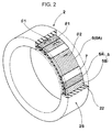
- the cord plies (5A, 5B) are each formed from a cord formation body in which reinforcing cords 8 are arrayed at an angle ( ⁇ 1) (illustrated in Fig. 2 ) with respect to a tire circumferential direction and a topping rubber 9 that covers a surface of the cord formation body.
- the reinforcing cords 8, a cord formation density and the angle ( ⁇ 1) of the first reinforcing cord layer 5 are appropriately set according to a tensile modulus (Eb 1 ) in the tire circumferential direction of the first reinforcing cord layer 5 (to be described later).
- the cord plies (5A, 5B) each include a cord formation body in which steel cords (reinforcing cords 8) are arrayed, for example, at an angle ( ⁇ 1) of 5 - 35 degrees.
- the cord plies (5A, 5B) are formed such that directions of inclination of the reinforcing cords 8 are different between the plies so that the reinforcing cords 8 intersect each other between the plies.
- the first reinforcing cord layer 5 can enhance an in-plane rigidity, and can improve turning performance by increasing a cornering power that is generated when a slip angle is applied.
- the second reinforcing cord layer 6 is formed from one cord ply (6A).
- the cord ply (6A) is formed from a cord formation body in which reinforcing cords 10 are arrayed at an angle ( ⁇ 2) (illustrated in Fig. 2 ) with respect to the tire circumferential direction and a topping rubber 11 that covers a surface of the cord formation body.
- the reinforcing cords 10, a cord formation density and the angle ( ⁇ 2) of the second reinforcing cord layer 6 are also set according to a tensile modulus (Eb 2 ) in the tire circumferential direction of the second reinforcing cord layer 6 (to be described later).
- the cord ply (6A) includes a cord formation body in which steel cords (reinforcing cords 10) are spirally wound at the angle ( ⁇ 2) of less than 5 degrees.
- the second reinforcing cord layer 6 can increase the tensile modulus (Eb 2 ) in the tire circumferential direction while achieving reduction in weight.
- the first and second reinforcing cord layers (5, 6) are respectively formed to be line-symmetric with respect to a tire equator line.
- torsion occurs in the reinforcing cord layer 5 and/or the reinforcing cord layer 6, and the tread ring 2 deforms by distortion, and thus smooth rolling becomes difficult.
- the topping rubbers (9, 11) that are used in the cord plies (5A, 5B, 6A) are formed of a sulfur vulcanized rubber composition that uses sulfur as a vulcanization agent, a rubber component of the sulfur vulcanized rubber composition being, for example, a natural rubber (NR), a butadiene rubber (BR), a diene rubber such as a styrene-butadiene rubber (SBR), or a mixture thereof.
- NR natural rubber
- BR butadiene rubber
- SBR styrene-butadiene rubber
- the shear rubber layer 7 is positioned between the first and second reinforcing cord layers (5, 6).
- a portion of a load that the tread ring 2 receives during traveling can be supported by a tensile elastic force in the tire circumferential direction of the first and second reinforcing cord layers (5, 6), and a deformation amount of the tread ring 2 can be suppressed by effectively increasing a load bearing capacity.
- a ratio (Eb 1 /Ee) and a ratio (Eb 2 /Ee) of the moduli are respectively set to be 100 or more.
- the ratio (Eb 1 /Ee) and the ratio (Eb 2 /Ee) are preferably 500 or more, and more preferably, 1000 or more.
- the tensile modulus (Eb 1 ) and the tensile modulus (Eb 2 ) may be different from each other.
- a ratio (Eb1/Eb2) between the tensile moduli (Eb 1 , Eb 2 ) be in a range of 0.8 - 1.2, and it is particularly preferable that the tensile moduli (Eb 1 , Eb 2 ) be equal to each other.
- the loss tangent (tan ⁇ b) is restricted to a range of 0.03 - 0.10
- the tensile modulus (E*b) is restricted to a range of 4 - 20 MPa.
- the loss tangent (tan ⁇ b) exceeds 0.10, it becomes difficult to sufficiently reduce the rolling resistance.
- the topping rubbers (9, 11) become weak, and it is difficult to ensure sufficient rigidity in the tread ring 2.
- an upper limit of the loss tangent (tan ⁇ b) be 0.05 or less.
- a lower limit of the tensile modulus (E*b) is preferably 8 MPa or more, and more preferably 12 MPa or more.
- the topping rubber 9 and the topping rubber 11 may be formed of different rubber compositions and have different loss tangents (tan ⁇ b) and tensile moduli (E*b). However, from a point of view of eliminating weakness, it is preferable that the topping rubbers (9, 11) be formed of the same rubber composition. When the topping rubbers (9, 11) are formed of different rubber compositions, the loss tangents (tan ⁇ b) and the tensile moduli (E*b) of the topping rubbers (9, 11) are respectively restricted to within the above-described ranges.
- each of the cord plies (5A, 5B, 6A) can be partitioned in a thickness direction thereof into a central region (Y1) in which the cord formation body and the topping rubber (9, 11) of the reinforcing cords (8, 10) are interposed, and a covering region (Y2) that is formed of only the topping rubber (9, 11).
- the covering region (Y2) is formed of only the topping rubber (9, 11) and thus has a low rigidity as compared to the central region (Y1) and the shear rubber layer 7 (to be described later).
- the covering thickness (Tb) is reduced to 0.5 mm or less.
- a lower limit of the covering thickness (Tb) be 0.1 mm or more.
- the shear modulus (Ee) of the shear rubber layer 7 be high.
- the shear rubber layer 7 be formed of a low heat generation rubber composition that has a small loss tangent (tan ⁇ ).
- the loss tangent (tan ⁇ ) of the shear rubber layer 7 is set to 0.06 or less.
- the rubber composition A has a low extensibility and is more brittle as compared to a normal sulfur vulcanized rubber composition, and thus is not used for a pneumatic tire.
- the shear rubber layer 7 is covered and protected by the first and second reinforcing cord layers (5, 6), and thus is not directly subjected to an impact from outside. Further, even when local bending occurs, the local bending is relaxed by the tread rubber layer 22 and the first and second reinforcing cord layers (5, 6), and thus the rubber composition A can be used without causing a problem in endurance strength.
- Table 1 illustrates a formulation example of the rubber composition A.
- Table 1 Shear Rubber Layer Rubber Composition A • Natural Rubber (NR) 10 • Butadiene Rubber (BR) 90 • Carbon Black 0 • ⁇ , ⁇ -Unsaturated Carboxylic Acid Metal Salt (Zinc Methacrylate) 40 • Peroxide 1 • Zinc oxide 0 • Sulfur 0 • Vulcanization Accelerator 0
- the rubber composition A contains 10 - 80 parts by weight of an ⁇ , ⁇ -unsaturated carboxylic acid metal salt with respect to 100 parts by mass of a rubber component of which a content rate of a butadiene rubber (BR) is 10 - 100% by mass, and contains a peroxide.
- a butadiene rubber (BR) is 10 - 100% by mass
- the butadiene rubber (BR) and the ⁇ , ⁇ -unsaturated carboxylic acid metal salt co-cross-link with each other with the peroxide as an initiator, and thereby, high elasticity and low heat generation, which are difficult to achieve in a sulfur vulcanized rubber material, are achieved.
- the rubber component contains 10 - 100% by mass of the butadiene rubber (BR) in the 100 parts by mass.
- examples of the rubber for the blending include a natural rubber (NR), a styrene butadiene rubber (SBR), an isoprene rubber (IR), a chloroprene rubber (CR), a styrene isoprene butadiene rubber (SIBR), a styrene-isoprene rubber (SIR), an epoxidized natural rubber (ENR), and the like.
- NR natural rubber
- SBR styrene butadiene rubber
- IR isoprene rubber
- CR chloroprene rubber
- SIBR styrene isoprene butadiene rubber
- SIR styrene-isoprene rubber
- EMR epoxidized natural rubber
- the content rate of the butadiene rubber (BR) is 10% or more by weight, and is preferably 20% or more by weight.
- an upper limit of the content rate of the butadiene rubber (BR) is preferably 90% or less by weight, and more preferably 80% or less by weight.
- the ⁇ , ⁇ -unsaturated carboxylic acid metal salt is adopted, which is a metal salt of an ⁇ , ⁇ -unsaturated carboxylic acid such as acrylic acid, methacrylic acid, maleic acid, fumaric acid, or itaconic acid.
- an acrylic acid metal salt and/or a methacrylic acid metal salt are preferable, and a methacrylic acid metal salt is even more preferable.
- the metal in the ⁇ , ⁇ -unsaturated carboxylic acid metal salt include zinc, sodium, magnesium, calcium, aluminum and the like, among which, zinc is preferred for allowing sufficient hardness to be obtained.
- the content of the co-cross-linking agent ( ⁇ , ⁇ -unsaturated carboxylic acid metal salt) is 10 - 80 parts by weight with respect to 100 parts by weight of the rubber component.
- ⁇ ⁇ -unsaturated carboxylic acid metal salt
- the content of the ⁇ , ⁇ -unsaturated carboxylic acid metal salt is below 10 parts by weight, a sufficient cross-link density cannot be obtained. Further, when the content of the ⁇ , ⁇ -unsaturated carboxylic acid metal salt exceeds 80 parts by weight, it becomes too hard and the strength is also reduced.
- a lower limit of the content of the ⁇ , ⁇ -unsaturated carboxylic acid metal salt is preferably 12 parts or more by weight
- an upper limit of the content of the ⁇ , ⁇ -unsaturated carboxylic acid metal salt is preferably 50 parts or less by weight and more preferably 35 parts or less by weight.
- peroxide examples include benzoyl peroxide, dicumyl peroxide, di-t-butyl peroxide, t-butyl cumyl peroxide, methyl ethyl ketone peroxide, cumene hydroperoxide, 2, 5-dimethyl-2, 5-di (t-butylperoxy) hexane, 2, 5-dimethyl-2, 5-di (benzoyl peroxy) hexane, t-butyl peroxy benzene, 2, 4-dichlorobenzoyl peroxide, 1, 1-di-t-butyl-peroxy-3, 3, 5-trimethyl cyclohexane, n-butyl-4, 4-di-t-butylperoxyvalerate, and the like. These may be used either individually or in combination of two or more. Among these, the dicumyl peroxide is preferable.
- the content of the peroxide be 0.1 - 6.0 parts by weight with respect to 100 parts by weight of the rubber component.
- the content of the peroxide is below 0.1 parts by weight, there is a tendency that a sufficient hardness cannot be obtained.
- the content of the peroxide exceeds 6 parts by weight, there is a tendency that the cross-link density becomes too high and the strength is reduced. From such a point of view, it is more preferable that a lower limit of the peroxide be 0.2 parts or more by weight and an upper limit of the peroxide be 2 parts or less by weight.
- the rubber composition A may also contain a reinforcing filler.
- the reinforcing filler include carbon black, silica, calcium carbonate, clay, talc, alumina, aluminum hydroxide, and the like. However, carbon black is particularly preferred.
- the content of the reinforcing filler is preferably 90 parts or less by weight and more preferably 50 parts or less by weight with respect to 100 parts by weight of the rubber component. When the content of the reinforcing filler exceeds 90 parts by weight, there is risk that excellent low heat generation cannot be achieved.
- the rubber composition A may also contain compounding agents that are used in tire industry, such as zinc oxide, wax, stearic acid, oil, an anti-aging agent, and a vulcanization accelerator, within ranges such that the effect of an embodiment of the present invention is not impaired.
- the rubber composition A contains the co-cross-linking agent ( ⁇ , ⁇ -unsaturated carboxylic acid metal salt), and thus does not contain a vulcanizing agent such as sulfur or a sulfur compound.
- a vulcanizing agent such as sulfur or a sulfur compound.
- sulfur contains in the topping rubbers of the reinforcing cord layers (5, 6) migrates to the shear rubber layer 7 and the physical properties of the shear rubber layer 7 are changed. Therefore, in the present example, as exaggeratedly illustrated in Fig.
- an insulation layer 25 that prevents the migration of sulfur be interposed between the first reinforcing cord layer 5 and the shear rubber layer 7 and between the second reinforcing cord layer 6 and the shear rubber layer 7.
- the insulation layer 25 is not particularly restricted.
- an adhesive such as CHEMLOK 6100 - 6254 (product name of LORD Corporation) or the like can achieve both an effect of preventing migration of sulfur and an effect of adhesion, and thus can be preferably adopted.
- the insulation layer 25 is not particularly restricted in thickness. However, when the insulation layer 25 is too thin, the effect of adhesion cannot be achieved; and when the insulation layer 25 is too thick, the adhesion layer itself becomes brittle and thus is likely to break. From such a point of view, the thickness of the insulation layer 25 is preferably 3 - 100 ⁇ m, and more preferably 7 - 50 ⁇ m.
- a tire axial direction width (We) of the shear rubber layer 7 be 0.6 - 0.99 times a tire axial direction width (Wr) of the tread ring 2, and tire axial direction widths (Wb 1 , Wb 2 ) of the first and second reinforcing cord layers (5, 6) be each 0.6 - 0.99 times the width (Wr).
- the load bearing capacity is achieved by the sandwich structure of the first and second reinforcing cord layers (5, 6) and the shear rubber layer 7. Therefore, the width (We) of the shear rubber layer 7 and the widths (Wb 1 , Wb 2 ) of the first and second reinforcing cord layers (5, 6) are respectively sufficiently wide with respect to the width (Wr) of the tread ring 2.
- the width (We) and the widths (Wb 1 , Wb 2 ) are each below 0.6 times the width (Wr), a sufficient load bearing capacity cannot be achieved.
- the width (We) and the widths (Wb 1 , Wb 2 ) be substantially equal to each other. Therefore, it is preferable that a ratio (Wmax/Wmin) between a maximum value (Wmax) and a minimum value (Wmin) among the width (We) and the widths (Wb 1 , Wb 2 ) be 1.1 or less.
- Airless tires (tires corresponding to a tire size of 145/70R12) that each form the basic structure of Fig. 1 were prototyped, and rolling resistance performance was tested. Specifications of the tires, except the tread ring, are substantially the same.
- the spoke was integrally formed with the tread ring and the hub using a cast molding method using a urethane resin (thermosetting resin).
- the first and second reinforcing cord layers are as follows.
- the tensile modulus (Eb 1 ) in the tire circumferential direction is changed by changing a diameter of the reinforcing cords, the number of the cords, and the angle of the cords.
- the prototyped tires were mounted on four wheels of a vehicle (small EV; product name: COMS).
- vehicle small EV; product name: COMS
- the vehicle driven by one person, was run on a tire test course with a dry asphalt road surface.
- Steering stability was displayed using a 10-point method based on sensory evaluation by the driver. A larger value means a better operation stability.
Abstract
Description
- The present invention relates to an airless tire that allows a rolling resistance to be reduced.
- An airless tire may have a structure in which a cylindrical tread ring and a hub are connected by multiple spoke plates. The cylindrical tread ring has a ground contact surface, the hub is fixed to an axle, and the spoke plates are radially arranged (for example, see Japanese Patent Laid-Open Publication No.
2014-218132 - According to one aspect of the present invention, an airless tire includes a tread ring which has a cylindrical form and a ground contact surface, a hub which is formed on a radial direction inner side of the tread ring and is to be fixed to an axle, and a spoke structure connecting the tread ring and the hub. The tread ring includes a tread rubber layer having the ground contact surface, a first reinforcing cord layer formed closest to the tread rubber layer, a second reinforcing cord layer formed on a radial direction inner side of the first reinforcing cord layer, and a shear rubber layer formed between the first and second reinforcing cord layers, the first and second reinforcing cord layers and the shear rubber layer are formed such that a ratio Eb1/Ee between a tire circumferential direction tensile modulus Eb1 of the first reinforcing cord layer and a shear modulus Ee of the shear rubber layer is 100 or greater and that a ratio Eb2/Ee between a tire circumferential direction tensile modulus Eb2 of the second reinforcing cord layer and the shear modulus Ee of the shear rubber layer is 100 or greater, and each of the first and second reinforcing cord layers has a topping rubber having a loss tangent tanδb in the range of 0.03 to 0.10 and a tensile modulus E*b in the range of 4 to 20 MPa.
- In an airless tire, for a tread rubber layer that forms the ground contact surface of a tread ring, a conventional rubber material for a pneumatic tire may be used, which may be advantageous from a point of view of grip performance, wear resistance, and the like.
- However, in a pneumatic tire, a load is supported by air that has a very small hysteresis loss, whereas in an airless tire, a load is supported by solid parts, specifically, a tread ring and spoke plates, that have large hysteresis losses as compared to the air. Therefore, when a tread component that is used for a tread part of a pneumatic tire is used "as is" for a tread ring of an airless tire, a problem occurs that a rolling resistance of the airless tire deteriorates to about 2.5 times of that of the pneumatic tire.
- Therefore, to reduce the rolling resistance of an airless tire to a level of a pneumatic tire, a tread ring using a structure different from a tread structure of a pneumatic tire and using a component having physical properties different from those of a tread component of a pneumatic tire is formed.
- An airless tire according to the present allows rolling resistance to be reduced while ensuring excellent steering stability, based on adopting a sandwich structure for a tread ring in which a shear rubber layer is sandwiched between first and second reinforcing cord layers, and respectively determining values of ratios between tire circumferential direction tensile moduli of the first and second reinforcing cord layers and a shear modulus of the shear rubber layer, and values of a loss tangent (tanδb) and a tensile modulus (E*b) of a topping rubber of each of the first and second reinforcing cord layers.
- An airless tire according to the present invention includes: a cylindrical tread ring that has a ground contact surface; a hub that is formed on a radial direction inner side of the tread ring and is fixed to an axle; and a spoke that connects the tread ring and the hub. The tread ring includes: a tread rubber layer that has the ground contact surface; a first reinforcing cord layer that is positioned closest to the tread rubber layer; a second reinforcing cord layer that is positioned on a radial direction inner side of the first reinforcing cord layer; and a shear rubber layer that is positioned between the first and second reinforcing cord layers. A ratio (Eb1/Ee) between a tire circumferential direction tensile modulus (Eb1) of the first reinforcing cord layer and a shear modulus (Ee) of the shear rubber layer and a ratio (Eb2/Ee) between a tire circumferential direction tensile modulus (Eb2) of the second reinforcing cord layer and the shear modulus (Ee) of the shear rubber layer are each 100 or more. A topping rubber of each of the first and second reinforcing cord layers has a loss tangent (tanδb) in a range of 0.03 - 0.10 and a tensile modulus (E*b) in a range of 4 - 20 MPa.
- In an airless tire according to the present invention, it is preferable that the shear modulus (Ee) be 20 MPa or more.
- In an airless tire according to the present invention, the tensile modulus (E*b) is preferably 8 MPa or more, and more preferably 12 MPa or more.
- In an airless tire according to the present invention, it is preferable that the topping rubber be formed of a sulfur vulcanized rubber composition that uses sulfur as a vulcanization agent.
- In an airless tire according to the present invention, it is preferable that a tire axial direction width (We) of the shear rubber layer be 0.6 - 0.99 times a tire axial direction width (Wr) of the tread ring, and tire axial direction widths (Wb1, Wb2) of the first and second reinforcing cord layers be each 0.6 - 0.99 times the width (Wr).
- In an airless tire according to the present invention, it is preferable that the topping rubber of each of the first and second reinforcing cord layers have a covering thickness (Tb) of 0.5 mm or less.
- In an airless tire according to the present invention, it is preferable that the shear rubber layer be formed of a rubber composition that contains 10 - 80 parts by weight of an α, β-unsaturated carboxylic acid metal salt with respect to 100 parts by mass of a rubber component of which a content rate of a butadiene rubber is 10 - 100% by mass, and contain a peroxide.
- The tire circumferential direction tensile moduli (Eb1, Eb2) of the first and second reinforcing cord layers are static tensile moduli that are measured according to JIS K6251 at a temperature of 30 °C and a tire circumferential direction extension of 2.00%. A test specimen may be formed by cutting from a tread ring after vulcanization, and may also be formed by press vulcanizing an unvulcanized reinforcing cord layer at a temperature of 170 °C for 20 minutes before the formation of a tread ring.
- The shear modulus (Ee) of the shear rubber layer is a value of 1/3 times a static tensile modulus that is measured according to JIS K6251 at a temperature of 30 °C and an extension of 2.00%. A test specimen may be formed by cutting from a tread ring after vulcanization, and may also be formed by press vulcanizing an unvulcanized shear rubber layer at a temperature of 170 °C for 20 minutes before the formation of a tread ring.
- The loss tangent (tanδb) and the tensile modulus (complex modulus) (E*b) of the topping rubber are values that are measured according to JIS-K6394 using a viscoelasticity spectrometer for predetermined initial strain (10%), dynamic strain (±1%), frequency (10Hz), deformation mode (tensile), and measurement temperature (30°C). A test specimen is formed by press vulcanizing a topping rubber at a temperature of 170 °C for 20 minutes before the formation of a reinforcing cord layer.
- In order to reduce rolling resistance of an airless tire, it is important that a low heat generation rubber having a low loss tangent (tanδ) be used for a rubber that is used in a tread ring and a deformation amount of the rubber be kept low.
- Therefore, in the present invention, as described above, a sandwich structure is adopted for a tread ring in which the shear rubber layer is sandwiched by the first and second reinforcing cord layers. Therefore, a portion of a load that the tread ring receives during traveling can be supported by a tensile elastic force in the circumferential direction of the first and second reinforcing cord layers, and the deformation amount of the tread ring can be kept low.
- In this case, when the tensile moduli (Eb1, Eb2) of the first and second reinforcing cord layers are too small as compared to the shear modulus (Ee) of the shear rubber layer, the above-described function due to the sandwich structure cannot be sufficiently achieved. Therefore, in order to keep low the deformation amount of the tread ring and to reduce the rolling resistance and improve steering stability, it is important that the ratios (Eb1/Ee) and (Eb2/Ee) be each 100 or more.
- On the other hand, for the topping rubbers of the first and second reinforcing cord layers, a smaller loss tangent (tanδb) and a higher tensile modulus (E*b) allow reduction in rolling resistance and reduction in weight to be achieved and are preferable for achieving low fuel consumption.
- As a sulfur vulcanized topping rubber used for a pneumatic tire, a rubber having a tensile modulus (E*b) of less than 4 MPa may be adopted. A reason for this is that, in a pneumatic tire, contribution to rigidity of the tire by increasing the tensile modulus (E*b) of the topping rubber is small and, from a point of view of factors in manufacturing, such as ease of molding, a rubber having a tensile modulus (E*b) of less than 4 MPa is adopted.
- However, in an airless tire, influence of properties of a rubber on properties of a tire is about 10 times that in the case of a pneumatic tire. This is due to that, in an airless tire, a load is entirely supported by components, whereas in a pneumatic tire, about 90% of a load is supported by the air.
- Therefore, in an airless tire, the influence of the topping rubber on the properties of the tire also becomes large. When the tensile modulus (E*b) of the topping rubber is 4 MPa or more, the rigidity of the tread ring is easily ensured, and a higher tensile modulus (E*b) is more preferable for achieving reduction in rolling resistance, reduction in weight, improvement in steering stability, and the like. However, in a sulfur vulcanized rubber composition, it is difficult in manufacturing to increase the tensile modulus (E*b) to above 20 MPa. Further, when the loss tangent (tanδb) of the topping rubber is 0.1 or less, the rolling resistance can be sufficiently reduced, and a lower loss tangent (tanδb) is more preferable for reducing the rolling resistance. However, in a sulfur vulcanized rubber composition, it is technically difficult to reduce the loss tangent (tanδb) to below 0.03. For this reason, the loss tangent (tanδb) of the topping rubber is restricted to 0.03 - 0.10, and the tensile modulus (E*b) of the topping rubber is restricted to 4 - 20 MPa.
- A more complete appreciation of the invention and many of the attendant advantages thereof will be readily obtained as the same becomes better understood by reference to the following detailed description when considered in connection with the accompanying drawings, wherein:
-
Fig. 1 is a perspective view illustrating an airless tire according to an embodiment of the present invention; -
Fig. 2 is a perspective view illustrating a tread ring ofFig. 1 ; -
Fig. 3 is an enlarged cross-sectional view of the tread ring ofFig. 2 ; -
Fig. 4A is a partial enlarged cross-sectional view illustrating first and second reinforcing cord layers together with a shear rubber layer; and -
Fig. 4B is a partial enlarged cross-sectional view illustrating a cord ply. - The embodiments will now be described with reference to the accompanying drawings, wherein like reference numerals designate corresponding or identical elements throughout the various drawings.
- As illustrated in
Fig. 1 , an airless tire 1 of the present embodiment includes acylindrical tread ring 2 that has a ground contact surface (2S), ahub 3 that is positioned on a radial direction inner side of thetread ring 2 and is fixed to an axle, and aspoke 4 that connects thetread ring 2 and thehub 3. In the present example, a case is illustrated where the airless tire 1 is formed as a passenger car tire. - The
hub 3 corresponds to a tire wheel, and includes a disk-shaped disk part 31 that is fixed to the axle and a cylindricalspoke attaching part 32 that is formed on an outer periphery of thedisk part 31. Similar to a tire wheel, thehub 3 is formed of a metal material such as steel, aluminum alloy or magnesium alloy. - The
spoke 4 includes multiple spoke plates (4A) that substantially radially extend and connect thetread ring 2 and thehub 3. Thespoke 4 is integrally molded with thetread ring 2 and thehub 3 by cast molding using a polymer material. As the polymer material, a thermoplastic resin or a thermosetting resin can be adopted. However, from a point of view of safety, a thermosetting resin, such as an epoxy resin, a phenolic resins, a urethane resin, a silicone resin, a polyimide resin, or a melamine resin, is preferred. In particular, a urethane resin has excellent elastic properties and thus can be more preferably adopted. - Next, as illustrated in
Fig. 2 and3 , thetread ring 2 includes atread rubber layer 22 that forms the ground contact surface (2S), a first reinforcingcord layer 5 that is positioned closest to thetread rubber layer 22, a second reinforcingcord layer 6 that is positioned on a tire radial direction inner side of the first reinforcingcord layer 5, and ashear rubber layer 7 that is positioned between the first and second reinforcing cord layers (5, 6). That is, thetread ring 2 has a sandwich structure in which theshear rubber layer 7 is sandwiched by the first and second reinforcing cord layers (5, 6). - On the ground contact surface (2S), which is an outer peripheral surface of the
tread ring 2, tread grooves (not illustrated in the drawings) are formed in various pattern shapes in order to impart wet performance. Similar to a pneumatic tire, a rubber composition that is superior in grip force against a road surface and in wear resistance is preferably adopted for thetread rubber layer 22. - As illustrated in
Fig. 4A , in the present example, the first reinforcingcord layer 5 is formed from a total of two cord plies (5A, 5B) that are respectively formed on radial direction inner and outer sides. The cord plies (5A, 5B) are each formed from a cord formation body in which reinforcingcords 8 are arrayed at an angle (θ1) (illustrated inFig. 2 ) with respect to a tire circumferential direction and a toppingrubber 9 that covers a surface of the cord formation body. The reinforcingcords 8, a cord formation density and the angle (θ1) of the first reinforcingcord layer 5 are appropriately set according to a tensile modulus (Eb1) in the tire circumferential direction of the first reinforcing cord layer 5 (to be described later). In the present example, the cord plies (5A, 5B) each include a cord formation body in which steel cords (reinforcing cords 8) are arrayed, for example, at an angle (θ1) of 5 - 35 degrees. Further, the cord plies (5A, 5B) are formed such that directions of inclination of the reinforcingcords 8 are different between the plies so that the reinforcingcords 8 intersect each other between the plies. As a result, the first reinforcingcord layer 5 can enhance an in-plane rigidity, and can improve turning performance by increasing a cornering power that is generated when a slip angle is applied. - In the present example, the second reinforcing
cord layer 6 is formed from one cord ply (6A). The cord ply (6A) is formed from a cord formation body in which reinforcingcords 10 are arrayed at an angle (θ2) (illustrated inFig. 2 ) with respect to the tire circumferential direction and a toppingrubber 11 that covers a surface of the cord formation body. The reinforcingcords 10, a cord formation density and the angle (θ2) of the second reinforcingcord layer 6 are also set according to a tensile modulus (Eb2) in the tire circumferential direction of the second reinforcing cord layer 6 (to be described later). In the present example, the cord ply (6A) includes a cord formation body in which steel cords (reinforcing cords 10) are spirally wound at the angle (θ2) of less than 5 degrees. As a result, the second reinforcingcord layer 6 can increase the tensile modulus (Eb2) in the tire circumferential direction while achieving reduction in weight. - The first and second reinforcing cord layers (5, 6) are respectively formed to be line-symmetric with respect to a tire equator line. When there is no line symmetry, when a load is applied, torsion occurs in the reinforcing
cord layer 5 and/or the reinforcingcord layer 6, and thetread ring 2 deforms by distortion, and thus smooth rolling becomes difficult. - In order to ensure adhesion to the reinforcing cords (8, 10), in the present example, the topping rubbers (9, 11) that are used in the cord plies (5A, 5B, 6A) are formed of a sulfur vulcanized rubber composition that uses sulfur as a vulcanization agent, a rubber component of the sulfur vulcanized rubber composition being, for example, a natural rubber (NR), a butadiene rubber (BR), a diene rubber such as a styrene-butadiene rubber (SBR), or a mixture thereof.
- Next, the
shear rubber layer 7 is positioned between the first and second reinforcing cord layers (5, 6). As a result, a portion of a load that thetread ring 2 receives during traveling can be supported by a tensile elastic force in the tire circumferential direction of the first and second reinforcing cord layers (5, 6), and a deformation amount of thetread ring 2 can be suppressed by effectively increasing a load bearing capacity. - In this case, when the tensile moduli (Eb1, Eb2) of the first and second reinforcing cord layers (5, 6) are not sufficiently larger than a shear modulus (Ee) of the
shear rubber layer 7, a function due to the sandwich structure cannot be achieved. Therefore, a ratio (Eb1/Ee) and a ratio (Eb2/Ee) of the moduli are respectively set to be 100 or more. As a result, the deformation amount of thetread ring 2 is kept low, and rolling resistance is reduced and excellent steering stability is ensured In particular, in order to suppress deformation of thetread ring 2, the ratio (Eb1/Ee) and the ratio (Eb2/Ee) are preferably 500 or more, and more preferably, 1000 or more. The tensile modulus (Eb1) and the tensile modulus (Eb2) may be different from each other. However, when the tensile modulus (Eb1) and the tensile modulus (Eb2) are different from each other, since one of the two reinforcing cord layers that has a higher tensile modulus becomes excessive in quality, it causes disadvantages in reduction in weight and in reduction in cost. Therefore, it is preferable that a ratio (Eb1/Eb2) between the tensile moduli (Eb1, Eb2) be in a range of 0.8 - 1.2, and it is particularly preferable that the tensile moduli (Eb1, Eb2) be equal to each other. - Further, as described above, in the airless tire 1, influence of properties of a rubber on properties of a tire is very large, about 10 times that in the case of a pneumatic tire. Therefore, also in the topping rubbers (9, 11), a small loss tangent (tanδb) and a high tensile modulus (E*b) are important for reduction in rolling resistance and reduction in weight.
- Therefore, the loss tangent (tanδb) is restricted to a range of 0.03 - 0.10, and the tensile modulus (E*b) is restricted to a range of 4 - 20 MPa. When the loss tangent (tanδb) exceeds 0.10, it becomes difficult to sufficiently reduce the rolling resistance. On the other hand, in a sulfur vulcanized rubber composition, it is technically difficult to reduce the loss tangent (tanδb) to below 0.03. Further, when the tensile modulus (E*b) is less than 4 MPa, the topping rubbers (9, 11) become weak, and it is difficult to ensure sufficient rigidity in the
tread ring 2. On the other hand, in a sulfur vulcanized rubber composition, it is difficult in manufacturing to increase the tensile modulus (E*b) to above 20 MPa. From such a point of view, it is preferable that an upper limit of the loss tangent (tanδb) be 0.05 or less. Further, a lower limit of the tensile modulus (E*b) is preferably 8 MPa or more, and more preferably 12 MPa or more. - The topping
rubber 9 and the toppingrubber 11 may be formed of different rubber compositions and have different loss tangents (tanδb) and tensile moduli (E*b). However, from a point of view of eliminating weakness, it is preferable that the topping rubbers (9, 11) be formed of the same rubber composition. When the topping rubbers (9, 11) are formed of different rubber compositions, the loss tangents (tanδb) and the tensile moduli (E*b) of the topping rubbers (9, 11) are respectively restricted to within the above-described ranges. - As illustrated in
Fig. 4B , each of the cord plies (5A, 5B, 6A) can be partitioned in a thickness direction thereof into a central region (Y1) in which the cord formation body and the topping rubber (9, 11) of the reinforcing cords (8, 10) are interposed, and a covering region (Y2) that is formed of only the topping rubber (9, 11). The covering region (Y2) is formed of only the topping rubber (9, 11) and thus has a low rigidity as compared to the central region (Y1) and the shear rubber layer 7 (to be described later). Therefore, in order to increase the rigidity of the entire sandwich structure, it is effective to reduce a thickness of the covering region (Y2) that has the lowest rigidity, that is, to reduce a covering thickness (Tb) of the topping rubber (9, 11). In the present example, the covering thickness (Tb) is reduced to 0.5 mm or less. As a result, it can contribute to the rigidity of the sandwich structure and thus thetread ring 2. It is preferable from a point of view of adhesion that a lower limit of the covering thickness (Tb) be 0.1 mm or more. - Further, it is also important that the shear modulus (Ee) of the
shear rubber layer 7 be high. The higher the shear modulus (Ee) is, the more the load bearing capacity is increased. Therefore, the shear modulus (Ee) is preferably set to 20 MPa or more, and more preferably 30 MPa or more. This allows both the above-described ratio (Eb1/Ee) and ratio (Eb2/Ee) and the load bearing capacity to be further increased. As a result, low rolling resistance performance and steering stability can be further improved, or reduction in the weight of thetread ring 2 can be achieved while ensuring low rolling resistance performance and steering stability at a certain level. It is preferable that a thickness of theshear rubber layer 7 be 3 mm or more. - On the other hand, in order to reduce rolling resistance, it is also important that the
shear rubber layer 7 be formed of a low heat generation rubber composition that has a small loss tangent (tanδ). As a result of an experiment, it is found that, when the loss tangent (tanδ) of theshear rubber layer 7 is about 0.06, a rolling resistance close to that of a pneumatic tire can be ensured. Therefore, in the present example, the loss tangent (tanδ) of theshear rubber layer 7 is set to 0.06 or less. - Here, in the case of a sulfur vulcanized rubber composition, when the loss tangent (tanδ) is reduced to 0.06 or less, the shear modulus (Ee) is also reduced. Therefore, in a sulfur vulcanized rubber composition, it is difficult to restrict the loss tangent (tanδ) to 0.06 or less and the shear modulus (Ee) to 20 MPa or more. In such a situation, as a result of a study, it is found that the above-described physical properties can be ensured by using, for example, a butadiene-based rubber composition A that uses an α, β-unsaturated carboxylic acid metal salt as a cross-linking agent. The rubber composition A has a low extensibility and is more brittle as compared to a normal sulfur vulcanized rubber composition, and thus is not used for a pneumatic tire. However, as in an embodiment of the present invention, when the rubber composition A is used as the
shear rubber layer 7 of the sandwich structure, theshear rubber layer 7 is covered and protected by the first and second reinforcing cord layers (5, 6), and thus is not directly subjected to an impact from outside. Further, even when local bending occurs, the local bending is relaxed by thetread rubber layer 22 and the first and second reinforcing cord layers (5, 6), and thus the rubber composition A can be used without causing a problem in endurance strength. - Next, the rubber composition A of the
shear rubber layer 7 is described. Table 1 illustrates a formulation example of the rubber composition A.Table 1 Shear Rubber Layer Rubber Composition A • Natural Rubber (NR) 10 • Butadiene Rubber (BR) 90 • Carbon Black 0 • α, β-Unsaturated Carboxylic Acid Metal Salt (Zinc Methacrylate) 40 • Peroxide 1 • Zinc oxide 0 • Sulfur 0 • Vulcanization Accelerator 0 - The rubber composition A contains 10 - 80 parts by weight of an α, β-unsaturated carboxylic acid metal salt with respect to 100 parts by mass of a rubber component of which a content rate of a butadiene rubber (BR) is 10 - 100% by mass, and contains a peroxide. In the rubber composition A, the butadiene rubber (BR) and the α, β-unsaturated carboxylic acid metal salt co-cross-link with each other with the peroxide as an initiator, and thereby, high elasticity and low heat generation, which are difficult to achieve in a sulfur vulcanized rubber material, are achieved.
- The rubber component contains 10 - 100% by mass of the butadiene rubber (BR) in the 100 parts by mass. When the butadiene rubber (BR) is used by being blended with another rubber, examples of the rubber for the blending include a natural rubber (NR), a styrene butadiene rubber (SBR), an isoprene rubber (IR), a chloroprene rubber (CR), a styrene isoprene butadiene rubber (SIBR), a styrene-isoprene rubber (SIR), an epoxidized natural rubber (ENR), and the like. These rubbers can be used either individually or in combination of two or more. Among these rubbers, NR is preferable for being excellent in low heat generation.
- The content rate of the butadiene rubber (BR) is 10% or more by weight, and is preferably 20% or more by weight. When the content rate of the butadiene rubber (BR) is below 10% by weight, there is a tendency that an effect on achieving low heat generation is reduced. Further, when the content rate of the butadiene rubber (BR) is 100% by weight, there is a tendency that strength is reduced. Therefore, an upper limit of the content rate of the butadiene rubber (BR) is preferably 90% or less by weight, and more preferably 80% or less by weight.
- As a co-cross-linking agent, the α, β-unsaturated carboxylic acid metal salt is adopted, which is a metal salt of an α, β-unsaturated carboxylic acid such as acrylic acid, methacrylic acid, maleic acid, fumaric acid, or itaconic acid. In particular, for being excellent in durability, an acrylic acid metal salt and/or a methacrylic acid metal salt are preferable, and a methacrylic acid metal salt is even more preferable. Further, examples of the metal in the α, β-unsaturated carboxylic acid metal salt include zinc, sodium, magnesium, calcium, aluminum and the like, among which, zinc is preferred for allowing sufficient hardness to be obtained.
- The content of the co-cross-linking agent (α, β-unsaturated carboxylic acid metal salt) is 10 - 80 parts by weight with respect to 100 parts by weight of the rubber component. When the content of the α, β-unsaturated carboxylic acid metal salt is below 10 parts by weight, a sufficient cross-link density cannot be obtained. Further, when the content of the α, β-unsaturated carboxylic acid metal salt exceeds 80 parts by weight, it becomes too hard and the strength is also reduced. From such a point of view, a lower limit of the content of the α, β-unsaturated carboxylic acid metal salt is preferably 12 parts or more by weight, and an upper limit of the content of the α, β-unsaturated carboxylic acid metal salt is preferably 50 parts or less by weight and more preferably 35 parts or less by weight.
- Examples of the peroxide include benzoyl peroxide, dicumyl peroxide, di-t-butyl peroxide, t-butyl cumyl peroxide, methyl ethyl ketone peroxide, cumene hydroperoxide, 2, 5-dimethyl-2, 5-di (t-butylperoxy) hexane, 2, 5-dimethyl-2, 5-di (benzoyl peroxy) hexane, t-butyl peroxy benzene, 2, 4-dichlorobenzoyl peroxide, 1, 1-di-t-butyl-peroxy-3, 3, 5-trimethyl cyclohexane, n-butyl-4, 4-di-t-butylperoxyvalerate, and the like. These may be used either individually or in combination of two or more. Among these, the dicumyl peroxide is preferable.
- It is preferable that the content of the peroxide be 0.1 - 6.0 parts by weight with respect to 100 parts by weight of the rubber component. When the content of the peroxide is below 0.1 parts by weight, there is a tendency that a sufficient hardness cannot be obtained. Further, when the content of the peroxide exceeds 6 parts by weight, there is a tendency that the cross-link density becomes too high and the strength is reduced. From such a point of view, it is more preferable that a lower limit of the peroxide be 0.2 parts or more by weight and an upper limit of the peroxide be 2 parts or less by weight.
- The rubber composition A may also contain a reinforcing filler. Examples of the reinforcing filler include carbon black, silica, calcium carbonate, clay, talc, alumina, aluminum hydroxide, and the like. However, carbon black is particularly preferred. When the reinforcing filler is contained, the content of the reinforcing filler is preferably 90 parts or less by weight and more preferably 50 parts or less by weight with respect to 100 parts by weight of the rubber component. When the content of the reinforcing filler exceeds 90 parts by weight, there is risk that excellent low heat generation cannot be achieved.
- In addition to the rubber component, the co-cross-linking agent (α, β-unsaturated carboxylic acid metal salt), the peroxide and the reinforcing filler, the rubber composition A may also contain compounding agents that are used in tire industry, such as zinc oxide, wax, stearic acid, oil, an anti-aging agent, and a vulcanization accelerator, within ranges such that the effect of an embodiment of the present invention is not impaired.
- The rubber composition A contains the co-cross-linking agent (α, β-unsaturated carboxylic acid metal salt), and thus does not contain a vulcanizing agent such as sulfur or a sulfur compound. However, when the
shear rubber layer 7 is adjacent to the first and second reinforcing cord layers (5, 6), there is a risk that, during vulcanization, sulfur contains in the topping rubbers of the reinforcing cord layers (5, 6) migrates to theshear rubber layer 7 and the physical properties of theshear rubber layer 7 are changed. Therefore, in the present example, as exaggeratedly illustrated inFig. 4 , it is preferable that aninsulation layer 25 that prevents the migration of sulfur be interposed between the first reinforcingcord layer 5 and theshear rubber layer 7 and between the second reinforcingcord layer 6 and theshear rubber layer 7. Theinsulation layer 25 is not particularly restricted. However, for example, an adhesive such as CHEMLOK 6100 - 6254 (product name of LORD Corporation) or the like can achieve both an effect of preventing migration of sulfur and an effect of adhesion, and thus can be preferably adopted. Theinsulation layer 25 is not particularly restricted in thickness. However, when theinsulation layer 25 is too thin, the effect of adhesion cannot be achieved; and when theinsulation layer 25 is too thick, the adhesion layer itself becomes brittle and thus is likely to break. From such a point of view, the thickness of theinsulation layer 25 is preferably 3 - 100 µm, and more preferably 7 - 50 µm. - Further, as illustrated in
Fig. 3 , it is preferable that a tire axial direction width (We) of theshear rubber layer 7 be 0.6 - 0.99 times a tire axial direction width (Wr) of thetread ring 2, and tire axial direction widths (Wb1, Wb2) of the first and second reinforcing cord layers (5, 6) be each 0.6 - 0.99 times the width (Wr). - In the
tread ring 2, the load bearing capacity is achieved by the sandwich structure of the first and second reinforcing cord layers (5, 6) and theshear rubber layer 7. Therefore, the width (We) of theshear rubber layer 7 and the widths (Wb1, Wb2) of the first and second reinforcing cord layers (5, 6) are respectively sufficiently wide with respect to the width (Wr) of thetread ring 2. When the width (We) and the widths (Wb1, Wb2) are each below 0.6 times the width (Wr), a sufficient load bearing capacity cannot be achieved. On the other hand, when the width (We) and the widths (Wb1, Wb2) each exceed 0.99 times the width (Wr), outer edges of the first and second reinforcing cord layers (5, 6) and theshear rubber layer 7 are likely to be exposed from side surfaces of thetread ring 2, and there is a risk that damages such as peeling may occur with the exposed portions of the first and second reinforcing cord layers (5, 6) and theshear rubber layer 7 as starting points. - Since the load bearing capacity is achieved by the sandwich structure, it is preferable that the width (We) and the widths (Wb1, Wb2) be substantially equal to each other. Therefore, it is preferable that a ratio (Wmax/Wmin) between a maximum value (Wmax) and a minimum value (Wmin) among the width (We) and the widths (Wb1, Wb2) be 1.1 or less.
- In the above, an embodiment of the present invention is described in detail. However, the present invention is not limited by the embodiment illustrated in the drawings, but can be carried out in various modified forms.
- Airless tires (tires corresponding to a tire size of 145/70R12) that each form the basic structure of
Fig. 1 were prototyped, and rolling resistance performance was tested. Specifications of the tires, except the tread ring, are substantially the same. The spoke was integrally formed with the tread ring and the hub using a cast molding method using a urethane resin (thermosetting resin). The first and second reinforcing cord layers are as follows. The tensile modulus (Eb1) in the tire circumferential direction is changed by changing a diameter of the reinforcing cords, the number of the cords, and the angle of the cords. -
- Number of Plies: 2
- Reinforcing Cords: Steel Cords
- Angle of Cords: +21 degrees or -21 degrees
-
- Number of Plies: 1
- Reinforcing Cords: Steel Cords
- Angle of Cords: 0 degree (spiral winding)
-
- Thickness: 4 mm
-
- (1) In Example 16, the rubber composition A having a basic composition as illustrated in Table 1 was used, and the shear modulus (Ee) was adjusted by adjusting the content of α, β-unsaturated carboxylic acid metal salt.
- (2) In Comparative Examples and Examples other than Example 16, a sulfur vulcanized rubber composition (B) that uses a diene rubber was used, and the shear modulus (Ee) was adjusted by adjusting the contents of carbon black and sulfur.
- As the topping rubber of the first and second reinforcing cord layers:
- (3) In all of Comparative Examples and Examples, a sulfur vulcanized rubber composition (C) that uses a diene rubber was used, and the loss tangent (tanδb) and the tensile modulus (E*b) were adjusted by adjusting the contents of carbon black and sulfur.
- A rolling resistance coefficient ((rolling resistance)/load ×104) that was measured using a rolling resistance tester under a condition in which a speed is 40 km/h and a load is 1.17 kN was displayed. A smaller value means a better rolling resistance.
- The prototyped tires were mounted on four wheels of a vehicle (small EV; product name: COMS). The vehicle, driven by one person, was run on a tire test course with a dry asphalt road surface. Steering stability was displayed using a 10-point method based on sensory evaluation by the driver. A larger value means a better operation stability.


- As illustrated in Table 2, it can be confirmed that the tires of the examples allow rolling resistance to be reduced.
- Obviously, numerous modifications and variations of the present invention are possible in light of the above teachings. It is therefore to be understood that within the scope of the appended claims, the invention may be practiced otherwise than as specifically described herein as long as being within the scope of the appended claims.
Claims (8)
- An airless tire, comprising:a tread ring having a cylindrical form and a ground contact surface;a hub formed on a radial direction inner side of the tread ring and configured to be fixed to an axle; anda spoke structure connecting the tread ring and the hub,wherein the tread ring comprises a tread rubber layer having the ground contact surface, a first reinforcing cord layer formed closest to the tread rubber layer, a second reinforcing cord layer formed on a radial direction inner side of the first reinforcing cord layer, and a shear rubber layer formed between the first and second reinforcing cord layers,
the first and second reinforcing cord layers and the shear rubber layer are formed such that a ratio Eb1/Ee between a tire circumferential direction tensile modulus Eb1 of the first reinforcing cord layer and a shear modulus Ee of the shear rubber layer is 100 or greater and that a ratio Eb2/Ee between a tire circumferential direction tensile modulus Eb2 of the second reinforcing cord layer and the shear modulus Ee of the shear rubber layer is 100 or greater, and each of the first and second reinforcing cord layers has a topping rubber having a loss tangent tanδb in a range of 0.03 to 0.10 and a tensile modulus E*b in a range of 4 to 20 MPa. - The airless tire according to Claim 1, wherein the shear modulus Ee is 20 MPa or greater.
- The airless tire according to Claim 1 or 2, wherein the tensile modulus E*b is 8 MPa or greater.
- The airless tire according to Claim 1 or 2, wherein the tensile modulus E*b is 12 MPa or greater.
- The airless tire according to any one of Claims 1 to 4, wherein the topping rubber is formed of a sulfur vulcanized rubber composition.
- The airless tire according to any one of Claims 1 to 5, wherein the shear rubber layer has a tire axial direction width We in a range of 0.6 to 0.99 times a tire axial direction width Wr of the tread ring, the first reinforcing cord layer has a tire axial direction width Wb1 in a range of 0.6 to 0.99 times the width Wr, and the second reinforcing cord layer has a tire axial direction width Wb2 in a range of 0.6 to 0.99 times the width Wr.
- The airless tire according to any one of Claims 1 to 6, wherein the topping rubber of the first reinforcing cord layer has a covering thickness Tb in a range of 0.5 mm or less, and the topping rubber of the second reinforcing cord layer has a covering thickness Tb in a range of 0.5 mm or less.
- The airless tire according to any one of Claims 1 to 7, wherein the shear rubber layer is formed of a rubber material formed from a rubber composition comprising a peroxide, a rubber component and an α, β-unsaturated carboxylic acid metal salt in an amount in a range of 10 to 80 parts by weight with respect to 100 parts by mass of the rubber component, and the rubber component comprises a butadiene rubber in a content rate in a range of 10 to 100% by mass.
Applications Claiming Priority (1)
| Application Number | Priority Date | Filing Date | Title |
|---|---|---|---|
| JP2015164781A JP6613716B2 (en) | 2015-08-24 | 2015-08-24 | Airless tire |
Publications (2)
| Publication Number | Publication Date |
|---|---|
| EP3135501A1 true EP3135501A1 (en) | 2017-03-01 |
| EP3135501B1 EP3135501B1 (en) | 2019-09-04 |
Family
ID=56507508
Family Applications (1)
| Application Number | Title | Priority Date | Filing Date |
|---|---|---|---|
| EP16180709.4A Active EP3135501B1 (en) | 2015-08-24 | 2016-07-22 | Airless tire |
Country Status (3)
| Country | Link |
|---|---|
| US (1) | US10603958B2 (en) |
| EP (1) | EP3135501B1 (en) |
| JP (1) | JP6613716B2 (en) |
Cited By (6)
| Publication number | Priority date | Publication date | Assignee | Title |
|---|---|---|---|---|
| EP3228482A1 (en) * | 2016-04-06 | 2017-10-11 | Sumitomo Rubber Industries, Ltd. | Airless tire |
| US10639934B2 (en) * | 2016-11-22 | 2020-05-05 | The Goodyear Tire & Rubber Company | Shear band for a structurally supported tire |
| US20210061008A1 (en) * | 2017-03-24 | 2021-03-04 | Camso Inc. | Wheel comprising a tire |
| KR20220029171A (en) * | 2020-09-01 | 2022-03-08 | 금호타이어 주식회사 | Non pneumatic tire |
| CN114945480A (en) * | 2019-12-16 | 2022-08-26 | 米其林集团总公司 | Non-pneumatic tire spoke with improved elastic engagement body |
| EP4144538A3 (en) * | 2021-09-01 | 2023-03-15 | The Goodyear Tire & Rubber Company | Non-pneumatic tire with improved shear band |
Families Citing this family (9)
| Publication number | Priority date | Publication date | Assignee | Title |
|---|---|---|---|---|
| EP3007909A4 (en) | 2013-06-15 | 2017-03-01 | Ronald Thompson | Annular ring and non-pneumatic tire |
| CA2976055A1 (en) | 2015-02-04 | 2016-08-11 | Advancing Mobility, Llc. | Non-pneumatic tire and other annular devices |
| US10696096B2 (en) * | 2015-12-08 | 2020-06-30 | The Goodyear Tire & Rubber Company | Non-pneumatic tire |
| WO2018227276A1 (en) | 2017-06-15 | 2018-12-20 | Camso Inc. | Wheel comprising a non-pneumatic tire |
| CN110809523A (en) * | 2017-06-30 | 2020-02-18 | 株式会社普利司通 | Reinforcing member for tire and tire using same |
| US20220041015A1 (en) * | 2018-12-28 | 2022-02-10 | Bridgestone Americas Tire Operations, Llc | Non-pneumatic tire having reinforced outer ring |
| JP7324088B2 (en) * | 2019-08-26 | 2023-08-09 | Toyo Tire株式会社 | non-pneumatic tires |
| WO2022039892A1 (en) * | 2020-08-18 | 2022-02-24 | Bridgestone Americas Tire Operations, Llc | Tire tread with a band layer |
| WO2023200435A1 (en) * | 2022-04-13 | 2023-10-19 | Compagnie Generale Des Etablissements Michelin | Non-pneumatic tire with reinforcing elements spaced inboard from an axial extent of the tread |
Citations (4)
| Publication number | Priority date | Publication date | Assignee | Title |
|---|---|---|---|---|
| US20070267116A1 (en) * | 1999-12-10 | 2007-11-22 | Rhyne Timothy B | Non-Pneumatic Tire |
| WO2009072420A1 (en) * | 2007-12-06 | 2009-06-11 | Sumitomo Rubber Industries, Ltd. | Run-flat tire |
| JP2012035792A (en) * | 2010-08-09 | 2012-02-23 | Toyo Tire & Rubber Co Ltd | Non-pneumatic tire |
| EP2801485A1 (en) * | 2013-05-07 | 2014-11-12 | Sumitomo Rubber Industries, Ltd. | Airless tire |
Family Cites Families (9)
| Publication number | Priority date | Publication date | Assignee | Title |
|---|---|---|---|---|
| US5307850A (en) * | 1988-09-14 | 1994-05-03 | The Goodyear Tire & Rubber Company | Pneumatic tire containing syndiotactic 1,2-polybutadiene |
| US5202363A (en) * | 1990-04-16 | 1993-04-13 | Bridgestone/Firestone, Inc. | Anhydrous metal salts of α,β-ethylenically unsaturated carboxylic acids and related methods |
| JP2892904B2 (en) * | 1993-04-16 | 1999-05-17 | 住友ゴム工業株式会社 | Pneumatic tire |
| JPH0747806A (en) * | 1993-08-06 | 1995-02-21 | Sumitomo Rubber Ind Ltd | Pneumatic tire |
| US6994134B2 (en) * | 2001-10-05 | 2006-02-07 | Michelin Recherche Et Technique S.A. | Structurally supported resilient tire and materials |
| JP4523815B2 (en) * | 2004-08-26 | 2010-08-11 | 住友ゴム工業株式会社 | Heavy duty pneumatic tire and manufacturing method thereof |
| JP2006335983A (en) * | 2005-06-06 | 2006-12-14 | Sumitomo Rubber Ind Ltd | Pneumatic tire |
| EP2689939B1 (en) * | 2011-03-24 | 2019-06-19 | Bridgestone Corporation | Steel cord for rubber article reinforcement and pneumatic radial tire using same |
| JP2014019303A (en) * | 2012-07-18 | 2014-02-03 | Sumitomo Rubber Ind Ltd | Tire for motorcycle |
-
2015
- 2015-08-24 JP JP2015164781A patent/JP6613716B2/en active Active
-
2016
- 2016-07-22 EP EP16180709.4A patent/EP3135501B1/en active Active
- 2016-07-26 US US15/219,746 patent/US10603958B2/en active Active
Patent Citations (5)
| Publication number | Priority date | Publication date | Assignee | Title |
|---|---|---|---|---|
| US20070267116A1 (en) * | 1999-12-10 | 2007-11-22 | Rhyne Timothy B | Non-Pneumatic Tire |
| WO2009072420A1 (en) * | 2007-12-06 | 2009-06-11 | Sumitomo Rubber Industries, Ltd. | Run-flat tire |
| JP2012035792A (en) * | 2010-08-09 | 2012-02-23 | Toyo Tire & Rubber Co Ltd | Non-pneumatic tire |
| EP2801485A1 (en) * | 2013-05-07 | 2014-11-12 | Sumitomo Rubber Industries, Ltd. | Airless tire |
| JP2014218132A (en) | 2013-05-07 | 2014-11-20 | 住友ゴム工業株式会社 | Airless tire |
Cited By (10)
| Publication number | Priority date | Publication date | Assignee | Title |
|---|---|---|---|---|
| EP3228482A1 (en) * | 2016-04-06 | 2017-10-11 | Sumitomo Rubber Industries, Ltd. | Airless tire |
| JP2017185925A (en) * | 2016-04-06 | 2017-10-12 | 住友ゴム工業株式会社 | Airless tire |
| CN107266722A (en) * | 2016-04-06 | 2017-10-20 | 住友橡胶工业株式会社 | Air-free tyre |
| CN107266722B (en) * | 2016-04-06 | 2021-02-09 | 住友橡胶工业株式会社 | Airless tire |
| US10639934B2 (en) * | 2016-11-22 | 2020-05-05 | The Goodyear Tire & Rubber Company | Shear band for a structurally supported tire |
| US20210061008A1 (en) * | 2017-03-24 | 2021-03-04 | Camso Inc. | Wheel comprising a tire |
| US11858300B2 (en) * | 2017-03-24 | 2024-01-02 | Camso Inc. | Wheel comprising a tire |
| CN114945480A (en) * | 2019-12-16 | 2022-08-26 | 米其林集团总公司 | Non-pneumatic tire spoke with improved elastic engagement body |
| KR20220029171A (en) * | 2020-09-01 | 2022-03-08 | 금호타이어 주식회사 | Non pneumatic tire |
| EP4144538A3 (en) * | 2021-09-01 | 2023-03-15 | The Goodyear Tire & Rubber Company | Non-pneumatic tire with improved shear band |
Also Published As
| Publication number | Publication date |
|---|---|
| JP2017043121A (en) | 2017-03-02 |
| JP6613716B2 (en) | 2019-12-04 |
| EP3135501B1 (en) | 2019-09-04 |
| US10603958B2 (en) | 2020-03-31 |
| US20170057294A1 (en) | 2017-03-02 |
Similar Documents
| Publication | Publication Date | Title |
|---|---|---|
| EP3135501B1 (en) | Airless tire | |
| US10155416B2 (en) | Airless tire | |
| EP3064371B1 (en) | Airless tire | |
| US10189310B2 (en) | Airless tire | |
| US9636950B2 (en) | Tire comprising a layer of circumferential reinforcing elements | |
| RU2470960C2 (en) | Layer, clinch part and tread formed using defined rubber mixture and pneumatic tyre with said components | |
| JP6467241B2 (en) | Airless tire | |
| JP2017520457A (en) | Tire with circumferential reinforcing element layer | |
| US10399386B2 (en) | Tire comprising a layer of circumferential reinforcement elements | |
| US10286730B2 (en) | Tire comprising a layer of circumferential reinforcement elements | |
| US10328750B2 (en) | Tire comprising a layer of circumferential reinforcing elements | |
| JPH11286203A (en) | Pneumatic tire | |
| JP6408937B2 (en) | Airless tire | |
| US10525775B2 (en) | Tire comprising a layer of circumferential reinforcement elements | |
| JP6487779B2 (en) | Airless tire | |
| WO2018074414A1 (en) | Pneumatic tire | |
| US10399385B2 (en) | Tire comprising a layer of circumferential reinforcing elements | |
| JPH01106706A (en) | Radial tire for car |
Legal Events
| Date | Code | Title | Description |
|---|---|---|---|
| PUAI | Public reference made under article 153(3) epc to a published international application that has entered the european phase |
Free format text: ORIGINAL CODE: 0009012 |
|
| STAA | Information on the status of an ep patent application or granted ep patent |
Free format text: STATUS: THE APPLICATION HAS BEEN PUBLISHED |
|
| AK | Designated contracting states |
Kind code of ref document: A1 Designated state(s): AL AT BE BG CH CY CZ DE DK EE ES FI FR GB GR HR HU IE IS IT LI LT LU LV MC MK MT NL NO PL PT RO RS SE SI SK SM TR |
|
| AX | Request for extension of the european patent |
Extension state: BA ME |
|
| STAA | Information on the status of an ep patent application or granted ep patent |
Free format text: STATUS: REQUEST FOR EXAMINATION WAS MADE |
|
| 17P | Request for examination filed |
Effective date: 20170328 |
|
| RBV | Designated contracting states (corrected) |
Designated state(s): AL AT BE BG CH CY CZ DE DK EE ES FI FR GB GR HR HU IE IS IT LI LT LU LV MC MK MT NL NO PL PT RO RS SE SI SK SM TR |
|
| STAA | Information on the status of an ep patent application or granted ep patent |
Free format text: STATUS: EXAMINATION IS IN PROGRESS |
|
| 17Q | First examination report despatched |
Effective date: 20180907 |
|
| GRAP | Despatch of communication of intention to grant a patent |
Free format text: ORIGINAL CODE: EPIDOSNIGR1 |
|
| STAA | Information on the status of an ep patent application or granted ep patent |
Free format text: STATUS: GRANT OF PATENT IS INTENDED |
|
| INTG | Intention to grant announced |
Effective date: 20190221 |
|
| GRAS | Grant fee paid |
Free format text: ORIGINAL CODE: EPIDOSNIGR3 |
|
| GRAA | (expected) grant |
Free format text: ORIGINAL CODE: 0009210 |
|
| STAA | Information on the status of an ep patent application or granted ep patent |
Free format text: STATUS: THE PATENT HAS BEEN GRANTED |
|
| AK | Designated contracting states |
Kind code of ref document: B1 Designated state(s): AL AT BE BG CH CY CZ DE DK EE ES FI FR GB GR HR HU IE IS IT LI LT LU LV MC MK MT NL NO PL PT RO RS SE SI SK SM TR |
|
| REG | Reference to a national code |
Ref country code: GB Ref legal event code: FG4D |
|
| REG | Reference to a national code |
Ref country code: CH Ref legal event code: EP |
|
| REG | Reference to a national code |
Ref country code: AT Ref legal event code: REF Ref document number: 1174841 Country of ref document: AT Kind code of ref document: T Effective date: 20190915 |
|
| REG | Reference to a national code |
Ref country code: DE Ref legal event code: R096 Ref document number: 602016019772 Country of ref document: DE |
|
| REG | Reference to a national code |
Ref country code: IE Ref legal event code: FG4D |
|
| REG | Reference to a national code |
Ref country code: NL Ref legal event code: MP Effective date: 20190904 |
|
| REG | Reference to a national code |
Ref country code: LT Ref legal event code: MG4D |
|
| PG25 | Lapsed in a contracting state [announced via postgrant information from national office to epo] |
Ref country code: HR Free format text: LAPSE BECAUSE OF FAILURE TO SUBMIT A TRANSLATION OF THE DESCRIPTION OR TO PAY THE FEE WITHIN THE PRESCRIBED TIME-LIMIT Effective date: 20190904 Ref country code: FI Free format text: LAPSE BECAUSE OF FAILURE TO SUBMIT A TRANSLATION OF THE DESCRIPTION OR TO PAY THE FEE WITHIN THE PRESCRIBED TIME-LIMIT Effective date: 20190904 Ref country code: LT Free format text: LAPSE BECAUSE OF FAILURE TO SUBMIT A TRANSLATION OF THE DESCRIPTION OR TO PAY THE FEE WITHIN THE PRESCRIBED TIME-LIMIT Effective date: 20190904 Ref country code: NO Free format text: LAPSE BECAUSE OF FAILURE TO SUBMIT A TRANSLATION OF THE DESCRIPTION OR TO PAY THE FEE WITHIN THE PRESCRIBED TIME-LIMIT Effective date: 20191204 Ref country code: BG Free format text: LAPSE BECAUSE OF FAILURE TO SUBMIT A TRANSLATION OF THE DESCRIPTION OR TO PAY THE FEE WITHIN THE PRESCRIBED TIME-LIMIT Effective date: 20191204 Ref country code: SE Free format text: LAPSE BECAUSE OF FAILURE TO SUBMIT A TRANSLATION OF THE DESCRIPTION OR TO PAY THE FEE WITHIN THE PRESCRIBED TIME-LIMIT Effective date: 20190904 |
|
| PG25 | Lapsed in a contracting state [announced via postgrant information from national office to epo] |
Ref country code: RS Free format text: LAPSE BECAUSE OF FAILURE TO SUBMIT A TRANSLATION OF THE DESCRIPTION OR TO PAY THE FEE WITHIN THE PRESCRIBED TIME-LIMIT Effective date: 20190904 Ref country code: LV Free format text: LAPSE BECAUSE OF FAILURE TO SUBMIT A TRANSLATION OF THE DESCRIPTION OR TO PAY THE FEE WITHIN THE PRESCRIBED TIME-LIMIT Effective date: 20190904 Ref country code: GR Free format text: LAPSE BECAUSE OF FAILURE TO SUBMIT A TRANSLATION OF THE DESCRIPTION OR TO PAY THE FEE WITHIN THE PRESCRIBED TIME-LIMIT Effective date: 20191205 Ref country code: AL Free format text: LAPSE BECAUSE OF FAILURE TO SUBMIT A TRANSLATION OF THE DESCRIPTION OR TO PAY THE FEE WITHIN THE PRESCRIBED TIME-LIMIT Effective date: 20190904 Ref country code: ES Free format text: LAPSE BECAUSE OF FAILURE TO SUBMIT A TRANSLATION OF THE DESCRIPTION OR TO PAY THE FEE WITHIN THE PRESCRIBED TIME-LIMIT Effective date: 20190904 |
|
| REG | Reference to a national code |
Ref country code: AT Ref legal event code: MK05 Ref document number: 1174841 Country of ref document: AT Kind code of ref document: T Effective date: 20190904 |
|
| PG25 | Lapsed in a contracting state [announced via postgrant information from national office to epo] |
Ref country code: PL Free format text: LAPSE BECAUSE OF FAILURE TO SUBMIT A TRANSLATION OF THE DESCRIPTION OR TO PAY THE FEE WITHIN THE PRESCRIBED TIME-LIMIT Effective date: 20190904 Ref country code: EE Free format text: LAPSE BECAUSE OF FAILURE TO SUBMIT A TRANSLATION OF THE DESCRIPTION OR TO PAY THE FEE WITHIN THE PRESCRIBED TIME-LIMIT Effective date: 20190904 Ref country code: AT Free format text: LAPSE BECAUSE OF FAILURE TO SUBMIT A TRANSLATION OF THE DESCRIPTION OR TO PAY THE FEE WITHIN THE PRESCRIBED TIME-LIMIT Effective date: 20190904 Ref country code: RO Free format text: LAPSE BECAUSE OF FAILURE TO SUBMIT A TRANSLATION OF THE DESCRIPTION OR TO PAY THE FEE WITHIN THE PRESCRIBED TIME-LIMIT Effective date: 20190904 Ref country code: IT Free format text: LAPSE BECAUSE OF FAILURE TO SUBMIT A TRANSLATION OF THE DESCRIPTION OR TO PAY THE FEE WITHIN THE PRESCRIBED TIME-LIMIT Effective date: 20190904 Ref country code: PT Free format text: LAPSE BECAUSE OF FAILURE TO SUBMIT A TRANSLATION OF THE DESCRIPTION OR TO PAY THE FEE WITHIN THE PRESCRIBED TIME-LIMIT Effective date: 20200106 Ref country code: NL Free format text: LAPSE BECAUSE OF FAILURE TO SUBMIT A TRANSLATION OF THE DESCRIPTION OR TO PAY THE FEE WITHIN THE PRESCRIBED TIME-LIMIT Effective date: 20190904 |
|
| PG25 | Lapsed in a contracting state [announced via postgrant information from national office to epo] |
Ref country code: SM Free format text: LAPSE BECAUSE OF FAILURE TO SUBMIT A TRANSLATION OF THE DESCRIPTION OR TO PAY THE FEE WITHIN THE PRESCRIBED TIME-LIMIT Effective date: 20190904 Ref country code: CZ Free format text: LAPSE BECAUSE OF FAILURE TO SUBMIT A TRANSLATION OF THE DESCRIPTION OR TO PAY THE FEE WITHIN THE PRESCRIBED TIME-LIMIT Effective date: 20190904 Ref country code: SK Free format text: LAPSE BECAUSE OF FAILURE TO SUBMIT A TRANSLATION OF THE DESCRIPTION OR TO PAY THE FEE WITHIN THE PRESCRIBED TIME-LIMIT Effective date: 20190904 Ref country code: IS Free format text: LAPSE BECAUSE OF FAILURE TO SUBMIT A TRANSLATION OF THE DESCRIPTION OR TO PAY THE FEE WITHIN THE PRESCRIBED TIME-LIMIT Effective date: 20200224 |
|
| REG | Reference to a national code |
Ref country code: DE Ref legal event code: R097 Ref document number: 602016019772 Country of ref document: DE |
|
| PLBE | No opposition filed within time limit |
Free format text: ORIGINAL CODE: 0009261 |
|
| STAA | Information on the status of an ep patent application or granted ep patent |
Free format text: STATUS: NO OPPOSITION FILED WITHIN TIME LIMIT |
|
| PG2D | Information on lapse in contracting state deleted |
Ref country code: IS |
|
| PG25 | Lapsed in a contracting state [announced via postgrant information from national office to epo] |
Ref country code: DK Free format text: LAPSE BECAUSE OF FAILURE TO SUBMIT A TRANSLATION OF THE DESCRIPTION OR TO PAY THE FEE WITHIN THE PRESCRIBED TIME-LIMIT Effective date: 20190904 Ref country code: IS Free format text: LAPSE BECAUSE OF FAILURE TO SUBMIT A TRANSLATION OF THE DESCRIPTION OR TO PAY THE FEE WITHIN THE PRESCRIBED TIME-LIMIT Effective date: 20200105 |
|
| 26N | No opposition filed |
Effective date: 20200605 |
|
| PG25 | Lapsed in a contracting state [announced via postgrant information from national office to epo] |
Ref country code: SI Free format text: LAPSE BECAUSE OF FAILURE TO SUBMIT A TRANSLATION OF THE DESCRIPTION OR TO PAY THE FEE WITHIN THE PRESCRIBED TIME-LIMIT Effective date: 20190904 |
|
| PG25 | Lapsed in a contracting state [announced via postgrant information from national office to epo] |
Ref country code: MC Free format text: LAPSE BECAUSE OF FAILURE TO SUBMIT A TRANSLATION OF THE DESCRIPTION OR TO PAY THE FEE WITHIN THE PRESCRIBED TIME-LIMIT Effective date: 20190904 |
|
| REG | Reference to a national code |
Ref country code: CH Ref legal event code: PL |
|
| GBPC | Gb: european patent ceased through non-payment of renewal fee |
Effective date: 20200722 |
|
| REG | Reference to a national code |
Ref country code: BE Ref legal event code: MM Effective date: 20200731 |
|
| PG25 | Lapsed in a contracting state [announced via postgrant information from national office to epo] |
Ref country code: GB Free format text: LAPSE BECAUSE OF NON-PAYMENT OF DUE FEES Effective date: 20200722 Ref country code: LU Free format text: LAPSE BECAUSE OF NON-PAYMENT OF DUE FEES Effective date: 20200722 Ref country code: LI Free format text: LAPSE BECAUSE OF NON-PAYMENT OF DUE FEES Effective date: 20200731 Ref country code: CH Free format text: LAPSE BECAUSE OF NON-PAYMENT OF DUE FEES Effective date: 20200731 |
|
| PG25 | Lapsed in a contracting state [announced via postgrant information from national office to epo] |
Ref country code: BE Free format text: LAPSE BECAUSE OF NON-PAYMENT OF DUE FEES Effective date: 20200731 |
|
| PG25 | Lapsed in a contracting state [announced via postgrant information from national office to epo] |
Ref country code: IE Free format text: LAPSE BECAUSE OF NON-PAYMENT OF DUE FEES Effective date: 20200722 |
|
| PG25 | Lapsed in a contracting state [announced via postgrant information from national office to epo] |
Ref country code: TR Free format text: LAPSE BECAUSE OF FAILURE TO SUBMIT A TRANSLATION OF THE DESCRIPTION OR TO PAY THE FEE WITHIN THE PRESCRIBED TIME-LIMIT Effective date: 20190904 Ref country code: MT Free format text: LAPSE BECAUSE OF FAILURE TO SUBMIT A TRANSLATION OF THE DESCRIPTION OR TO PAY THE FEE WITHIN THE PRESCRIBED TIME-LIMIT Effective date: 20190904 Ref country code: CY Free format text: LAPSE BECAUSE OF FAILURE TO SUBMIT A TRANSLATION OF THE DESCRIPTION OR TO PAY THE FEE WITHIN THE PRESCRIBED TIME-LIMIT Effective date: 20190904 |
|
| PG25 | Lapsed in a contracting state [announced via postgrant information from national office to epo] |
Ref country code: MK Free format text: LAPSE BECAUSE OF FAILURE TO SUBMIT A TRANSLATION OF THE DESCRIPTION OR TO PAY THE FEE WITHIN THE PRESCRIBED TIME-LIMIT Effective date: 20190904 |
|
| P01 | Opt-out of the competence of the unified patent court (upc) registered |
Effective date: 20230510 |
|
| PGFP | Annual fee paid to national office [announced via postgrant information from national office to epo] |
Ref country code: FR Payment date: 20230620 Year of fee payment: 8 |
|
| PGFP | Annual fee paid to national office [announced via postgrant information from national office to epo] |
Ref country code: DE Payment date: 20230531 Year of fee payment: 8 |