EP3135451A1 - Manufacturing method of a protective cover for a bearing device having a sensor holder part - Google Patents
Manufacturing method of a protective cover for a bearing device having a sensor holder part Download PDFInfo
- Publication number
- EP3135451A1 EP3135451A1 EP16183928.7A EP16183928A EP3135451A1 EP 3135451 A1 EP3135451 A1 EP 3135451A1 EP 16183928 A EP16183928 A EP 16183928A EP 3135451 A1 EP3135451 A1 EP 3135451A1
- Authority
- EP
- European Patent Office
- Prior art keywords
- adhesive
- temperature
- protective cover
- drying
- sensor holder
- Prior art date
- Legal status (The legal status is an assumption and is not a legal conclusion. Google has not performed a legal analysis and makes no representation as to the accuracy of the status listed.)
- Withdrawn
Links
Images


Classifications
-
- B—PERFORMING OPERATIONS; TRANSPORTING
- B29—WORKING OF PLASTICS; WORKING OF SUBSTANCES IN A PLASTIC STATE IN GENERAL
- B29C—SHAPING OR JOINING OF PLASTICS; SHAPING OF MATERIAL IN A PLASTIC STATE, NOT OTHERWISE PROVIDED FOR; AFTER-TREATMENT OF THE SHAPED PRODUCTS, e.g. REPAIRING
- B29C45/00—Injection moulding, i.e. forcing the required volume of moulding material through a nozzle into a closed mould; Apparatus therefor
- B29C45/14—Injection moulding, i.e. forcing the required volume of moulding material through a nozzle into a closed mould; Apparatus therefor incorporating preformed parts or layers, e.g. injection moulding around inserts or for coating articles
- B29C45/14311—Injection moulding, i.e. forcing the required volume of moulding material through a nozzle into a closed mould; Apparatus therefor incorporating preformed parts or layers, e.g. injection moulding around inserts or for coating articles using means for bonding the coating to the articles
-
- B—PERFORMING OPERATIONS; TRANSPORTING
- B29—WORKING OF PLASTICS; WORKING OF SUBSTANCES IN A PLASTIC STATE IN GENERAL
- B29C—SHAPING OR JOINING OF PLASTICS; SHAPING OF MATERIAL IN A PLASTIC STATE, NOT OTHERWISE PROVIDED FOR; AFTER-TREATMENT OF THE SHAPED PRODUCTS, e.g. REPAIRING
- B29C69/00—Combinations of shaping techniques not provided for in a single one of main groups B29C39/00 - B29C67/00, e.g. associations of moulding and joining techniques; Apparatus therefore
- B29C69/02—Combinations of shaping techniques not provided for in a single one of main groups B29C39/00 - B29C67/00, e.g. associations of moulding and joining techniques; Apparatus therefore of moulding techniques only
-
- B—PERFORMING OPERATIONS; TRANSPORTING
- B29—WORKING OF PLASTICS; WORKING OF SUBSTANCES IN A PLASTIC STATE IN GENERAL
- B29C—SHAPING OR JOINING OF PLASTICS; SHAPING OF MATERIAL IN A PLASTIC STATE, NOT OTHERWISE PROVIDED FOR; AFTER-TREATMENT OF THE SHAPED PRODUCTS, e.g. REPAIRING
- B29C37/00—Component parts, details, accessories or auxiliary operations, not covered by group B29C33/00 or B29C35/00
- B29C37/0025—Applying surface layers, e.g. coatings, decorative layers, printed layers, to articles during shaping, e.g. in-mould printing
- B29C37/0028—In-mould coating, e.g. by introducing the coating material into the mould after forming the article
-
- B—PERFORMING OPERATIONS; TRANSPORTING
- B29—WORKING OF PLASTICS; WORKING OF SUBSTANCES IN A PLASTIC STATE IN GENERAL
- B29C—SHAPING OR JOINING OF PLASTICS; SHAPING OF MATERIAL IN A PLASTIC STATE, NOT OTHERWISE PROVIDED FOR; AFTER-TREATMENT OF THE SHAPED PRODUCTS, e.g. REPAIRING
- B29C45/00—Injection moulding, i.e. forcing the required volume of moulding material through a nozzle into a closed mould; Apparatus therefor
- B29C45/14—Injection moulding, i.e. forcing the required volume of moulding material through a nozzle into a closed mould; Apparatus therefor incorporating preformed parts or layers, e.g. injection moulding around inserts or for coating articles
- B29C45/1459—Coating annular articles
-
- B—PERFORMING OPERATIONS; TRANSPORTING
- B29—WORKING OF PLASTICS; WORKING OF SUBSTANCES IN A PLASTIC STATE IN GENERAL
- B29C—SHAPING OR JOINING OF PLASTICS; SHAPING OF MATERIAL IN A PLASTIC STATE, NOT OTHERWISE PROVIDED FOR; AFTER-TREATMENT OF THE SHAPED PRODUCTS, e.g. REPAIRING
- B29C65/00—Joining or sealing of preformed parts, e.g. welding of plastics materials; Apparatus therefor
- B29C65/48—Joining or sealing of preformed parts, e.g. welding of plastics materials; Apparatus therefor using adhesives, i.e. using supplementary joining material; solvent bonding
- B29C65/52—Joining or sealing of preformed parts, e.g. welding of plastics materials; Apparatus therefor using adhesives, i.e. using supplementary joining material; solvent bonding characterised by the way of applying the adhesive
- B29C65/521—Joining or sealing of preformed parts, e.g. welding of plastics materials; Apparatus therefor using adhesives, i.e. using supplementary joining material; solvent bonding characterised by the way of applying the adhesive by spin coating
-
- B—PERFORMING OPERATIONS; TRANSPORTING
- B29—WORKING OF PLASTICS; WORKING OF SUBSTANCES IN A PLASTIC STATE IN GENERAL
- B29C—SHAPING OR JOINING OF PLASTICS; SHAPING OF MATERIAL IN A PLASTIC STATE, NOT OTHERWISE PROVIDED FOR; AFTER-TREATMENT OF THE SHAPED PRODUCTS, e.g. REPAIRING
- B29C65/00—Joining or sealing of preformed parts, e.g. welding of plastics materials; Apparatus therefor
- B29C65/48—Joining or sealing of preformed parts, e.g. welding of plastics materials; Apparatus therefor using adhesives, i.e. using supplementary joining material; solvent bonding
- B29C65/52—Joining or sealing of preformed parts, e.g. welding of plastics materials; Apparatus therefor using adhesives, i.e. using supplementary joining material; solvent bonding characterised by the way of applying the adhesive
- B29C65/54—Joining or sealing of preformed parts, e.g. welding of plastics materials; Apparatus therefor using adhesives, i.e. using supplementary joining material; solvent bonding characterised by the way of applying the adhesive between pre-assembled parts
-
- B—PERFORMING OPERATIONS; TRANSPORTING
- B29—WORKING OF PLASTICS; WORKING OF SUBSTANCES IN A PLASTIC STATE IN GENERAL
- B29C—SHAPING OR JOINING OF PLASTICS; SHAPING OF MATERIAL IN A PLASTIC STATE, NOT OTHERWISE PROVIDED FOR; AFTER-TREATMENT OF THE SHAPED PRODUCTS, e.g. REPAIRING
- B29C66/00—General aspects of processes or apparatus for joining preformed parts
- B29C66/01—General aspects dealing with the joint area or with the area to be joined
- B29C66/03—After-treatments in the joint area
-
- B—PERFORMING OPERATIONS; TRANSPORTING
- B29—WORKING OF PLASTICS; WORKING OF SUBSTANCES IN A PLASTIC STATE IN GENERAL
- B29C—SHAPING OR JOINING OF PLASTICS; SHAPING OF MATERIAL IN A PLASTIC STATE, NOT OTHERWISE PROVIDED FOR; AFTER-TREATMENT OF THE SHAPED PRODUCTS, e.g. REPAIRING
- B29C66/00—General aspects of processes or apparatus for joining preformed parts
- B29C66/70—General aspects of processes or apparatus for joining preformed parts characterised by the composition, physical properties or the structure of the material of the parts to be joined; Joining with non-plastics material
- B29C66/74—Joining plastics material to non-plastics material
- B29C66/742—Joining plastics material to non-plastics material to metals or their alloys
-
- B—PERFORMING OPERATIONS; TRANSPORTING
- B29—WORKING OF PLASTICS; WORKING OF SUBSTANCES IN A PLASTIC STATE IN GENERAL
- B29C—SHAPING OR JOINING OF PLASTICS; SHAPING OF MATERIAL IN A PLASTIC STATE, NOT OTHERWISE PROVIDED FOR; AFTER-TREATMENT OF THE SHAPED PRODUCTS, e.g. REPAIRING
- B29C71/00—After-treatment of articles without altering their shape; Apparatus therefor
- B29C71/02—Thermal after-treatment
-
- B—PERFORMING OPERATIONS; TRANSPORTING
- B60—VEHICLES IN GENERAL
- B60B—VEHICLE WHEELS; CASTORS; AXLES FOR WHEELS OR CASTORS; INCREASING WHEEL ADHESION
- B60B27/00—Hubs
- B60B27/0047—Hubs characterised by functional integration of other elements
- B60B27/0068—Hubs characterised by functional integration of other elements the element being a sensor
-
- B—PERFORMING OPERATIONS; TRANSPORTING
- B60—VEHICLES IN GENERAL
- B60B—VEHICLE WHEELS; CASTORS; AXLES FOR WHEELS OR CASTORS; INCREASING WHEEL ADHESION
- B60B27/00—Hubs
- B60B27/0073—Hubs characterised by sealing means
-
- C—CHEMISTRY; METALLURGY
- C09—DYES; PAINTS; POLISHES; NATURAL RESINS; ADHESIVES; COMPOSITIONS NOT OTHERWISE PROVIDED FOR; APPLICATIONS OF MATERIALS NOT OTHERWISE PROVIDED FOR
- C09J—ADHESIVES; NON-MECHANICAL ASPECTS OF ADHESIVE PROCESSES IN GENERAL; ADHESIVE PROCESSES NOT PROVIDED FOR ELSEWHERE; USE OF MATERIALS AS ADHESIVES
- C09J5/00—Adhesive processes in general; Adhesive processes not provided for elsewhere, e.g. relating to primers
- C09J5/06—Adhesive processes in general; Adhesive processes not provided for elsewhere, e.g. relating to primers involving heating of the applied adhesive
-
- F—MECHANICAL ENGINEERING; LIGHTING; HEATING; WEAPONS; BLASTING
- F16—ENGINEERING ELEMENTS AND UNITS; GENERAL MEASURES FOR PRODUCING AND MAINTAINING EFFECTIVE FUNCTIONING OF MACHINES OR INSTALLATIONS; THERMAL INSULATION IN GENERAL
- F16C—SHAFTS; FLEXIBLE SHAFTS; ELEMENTS OR CRANKSHAFT MECHANISMS; ROTARY BODIES OTHER THAN GEARING ELEMENTS; BEARINGS
- F16C33/00—Parts of bearings; Special methods for making bearings or parts thereof
- F16C33/72—Sealings
- F16C33/723—Shaft end sealing means, e.g. cup-shaped caps or covers
-
- F—MECHANICAL ENGINEERING; LIGHTING; HEATING; WEAPONS; BLASTING
- F16—ENGINEERING ELEMENTS AND UNITS; GENERAL MEASURES FOR PRODUCING AND MAINTAINING EFFECTIVE FUNCTIONING OF MACHINES OR INSTALLATIONS; THERMAL INSULATION IN GENERAL
- F16C—SHAFTS; FLEXIBLE SHAFTS; ELEMENTS OR CRANKSHAFT MECHANISMS; ROTARY BODIES OTHER THAN GEARING ELEMENTS; BEARINGS
- F16C33/00—Parts of bearings; Special methods for making bearings or parts thereof
- F16C33/72—Sealings
- F16C33/76—Sealings of ball or roller bearings
- F16C33/78—Sealings of ball or roller bearings with a diaphragm, disc, or ring, with or without resilient members
- F16C33/7816—Details of the sealing or parts thereof, e.g. geometry, material
- F16C33/7833—Special methods of manufacture
-
- F—MECHANICAL ENGINEERING; LIGHTING; HEATING; WEAPONS; BLASTING
- F16—ENGINEERING ELEMENTS AND UNITS; GENERAL MEASURES FOR PRODUCING AND MAINTAINING EFFECTIVE FUNCTIONING OF MACHINES OR INSTALLATIONS; THERMAL INSULATION IN GENERAL
- F16C—SHAFTS; FLEXIBLE SHAFTS; ELEMENTS OR CRANKSHAFT MECHANISMS; ROTARY BODIES OTHER THAN GEARING ELEMENTS; BEARINGS
- F16C41/00—Other accessories, e.g. devices integrated in the bearing not relating to the bearing function as such
- F16C41/007—Encoders, e.g. parts with a plurality of alternating magnetic poles
-
- G—PHYSICS
- G01—MEASURING; TESTING
- G01P—MEASURING LINEAR OR ANGULAR SPEED, ACCELERATION, DECELERATION, OR SHOCK; INDICATING PRESENCE, ABSENCE, OR DIRECTION, OF MOVEMENT
- G01P1/00—Details of instruments
- G01P1/02—Housings
- G01P1/026—Housings for speed measuring devices, e.g. pulse generator
-
- G—PHYSICS
- G01—MEASURING; TESTING
- G01P—MEASURING LINEAR OR ANGULAR SPEED, ACCELERATION, DECELERATION, OR SHOCK; INDICATING PRESENCE, ABSENCE, OR DIRECTION, OF MOVEMENT
- G01P3/00—Measuring linear or angular speed; Measuring differences of linear or angular speeds
- G01P3/42—Devices characterised by the use of electric or magnetic means
- G01P3/44—Devices characterised by the use of electric or magnetic means for measuring angular speed
- G01P3/443—Devices characterised by the use of electric or magnetic means for measuring angular speed mounted in bearings
-
- G—PHYSICS
- G01—MEASURING; TESTING
- G01P—MEASURING LINEAR OR ANGULAR SPEED, ACCELERATION, DECELERATION, OR SHOCK; INDICATING PRESENCE, ABSENCE, OR DIRECTION, OF MOVEMENT
- G01P3/00—Measuring linear or angular speed; Measuring differences of linear or angular speeds
- G01P3/42—Devices characterised by the use of electric or magnetic means
- G01P3/44—Devices characterised by the use of electric or magnetic means for measuring angular speed
- G01P3/48—Devices characterised by the use of electric or magnetic means for measuring angular speed by measuring frequency of generated current or voltage
- G01P3/481—Devices characterised by the use of electric or magnetic means for measuring angular speed by measuring frequency of generated current or voltage of pulse signals
- G01P3/487—Devices characterised by the use of electric or magnetic means for measuring angular speed by measuring frequency of generated current or voltage of pulse signals delivered by rotating magnets
-
- B—PERFORMING OPERATIONS; TRANSPORTING
- B29—WORKING OF PLASTICS; WORKING OF SUBSTANCES IN A PLASTIC STATE IN GENERAL
- B29C—SHAPING OR JOINING OF PLASTICS; SHAPING OF MATERIAL IN A PLASTIC STATE, NOT OTHERWISE PROVIDED FOR; AFTER-TREATMENT OF THE SHAPED PRODUCTS, e.g. REPAIRING
- B29C37/00—Component parts, details, accessories or auxiliary operations, not covered by group B29C33/00 or B29C35/00
- B29C37/0025—Applying surface layers, e.g. coatings, decorative layers, printed layers, to articles during shaping, e.g. in-mould printing
- B29C37/0028—In-mould coating, e.g. by introducing the coating material into the mould after forming the article
- B29C2037/0035—In-mould coating, e.g. by introducing the coating material into the mould after forming the article the coating being applied as liquid, gel, paste or the like
-
- B—PERFORMING OPERATIONS; TRANSPORTING
- B29—WORKING OF PLASTICS; WORKING OF SUBSTANCES IN A PLASTIC STATE IN GENERAL
- B29C—SHAPING OR JOINING OF PLASTICS; SHAPING OF MATERIAL IN A PLASTIC STATE, NOT OTHERWISE PROVIDED FOR; AFTER-TREATMENT OF THE SHAPED PRODUCTS, e.g. REPAIRING
- B29C45/00—Injection moulding, i.e. forcing the required volume of moulding material through a nozzle into a closed mould; Apparatus therefor
- B29C45/14—Injection moulding, i.e. forcing the required volume of moulding material through a nozzle into a closed mould; Apparatus therefor incorporating preformed parts or layers, e.g. injection moulding around inserts or for coating articles
- B29C45/14311—Injection moulding, i.e. forcing the required volume of moulding material through a nozzle into a closed mould; Apparatus therefor incorporating preformed parts or layers, e.g. injection moulding around inserts or for coating articles using means for bonding the coating to the articles
- B29C2045/14319—Injection moulding, i.e. forcing the required volume of moulding material through a nozzle into a closed mould; Apparatus therefor incorporating preformed parts or layers, e.g. injection moulding around inserts or for coating articles using means for bonding the coating to the articles bonding by a fusion bond
-
- B—PERFORMING OPERATIONS; TRANSPORTING
- B29—WORKING OF PLASTICS; WORKING OF SUBSTANCES IN A PLASTIC STATE IN GENERAL
- B29L—INDEXING SCHEME ASSOCIATED WITH SUBCLASS B29C, RELATING TO PARTICULAR ARTICLES
- B29L2031/00—Other particular articles
- B29L2031/04—Bearings
-
- B—PERFORMING OPERATIONS; TRANSPORTING
- B29—WORKING OF PLASTICS; WORKING OF SUBSTANCES IN A PLASTIC STATE IN GENERAL
- B29L—INDEXING SCHEME ASSOCIATED WITH SUBCLASS B29C, RELATING TO PARTICULAR ARTICLES
- B29L2031/00—Other particular articles
- B29L2031/752—Measuring equipment
-
- C—CHEMISTRY; METALLURGY
- C09—DYES; PAINTS; POLISHES; NATURAL RESINS; ADHESIVES; COMPOSITIONS NOT OTHERWISE PROVIDED FOR; APPLICATIONS OF MATERIALS NOT OTHERWISE PROVIDED FOR
- C09J—ADHESIVES; NON-MECHANICAL ASPECTS OF ADHESIVE PROCESSES IN GENERAL; ADHESIVE PROCESSES NOT PROVIDED FOR ELSEWHERE; USE OF MATERIALS AS ADHESIVES
- C09J2400/00—Presence of inorganic and organic materials
- C09J2400/10—Presence of inorganic materials
- C09J2400/16—Metal
- C09J2400/163—Metal in the substrate
-
- C—CHEMISTRY; METALLURGY
- C09—DYES; PAINTS; POLISHES; NATURAL RESINS; ADHESIVES; COMPOSITIONS NOT OTHERWISE PROVIDED FOR; APPLICATIONS OF MATERIALS NOT OTHERWISE PROVIDED FOR
- C09J—ADHESIVES; NON-MECHANICAL ASPECTS OF ADHESIVE PROCESSES IN GENERAL; ADHESIVE PROCESSES NOT PROVIDED FOR ELSEWHERE; USE OF MATERIALS AS ADHESIVES
- C09J2400/00—Presence of inorganic and organic materials
- C09J2400/20—Presence of organic materials
- C09J2400/22—Presence of unspecified polymer
- C09J2400/226—Presence of unspecified polymer in the substrate
-
- C—CHEMISTRY; METALLURGY
- C09—DYES; PAINTS; POLISHES; NATURAL RESINS; ADHESIVES; COMPOSITIONS NOT OTHERWISE PROVIDED FOR; APPLICATIONS OF MATERIALS NOT OTHERWISE PROVIDED FOR
- C09J—ADHESIVES; NON-MECHANICAL ASPECTS OF ADHESIVE PROCESSES IN GENERAL; ADHESIVE PROCESSES NOT PROVIDED FOR ELSEWHERE; USE OF MATERIALS AS ADHESIVES
- C09J2461/00—Presence of condensation polymers of aldehydes or ketones
-
- F—MECHANICAL ENGINEERING; LIGHTING; HEATING; WEAPONS; BLASTING
- F16—ENGINEERING ELEMENTS AND UNITS; GENERAL MEASURES FOR PRODUCING AND MAINTAINING EFFECTIVE FUNCTIONING OF MACHINES OR INSTALLATIONS; THERMAL INSULATION IN GENERAL
- F16C—SHAFTS; FLEXIBLE SHAFTS; ELEMENTS OR CRANKSHAFT MECHANISMS; ROTARY BODIES OTHER THAN GEARING ELEMENTS; BEARINGS
- F16C19/00—Bearings with rolling contact, for exclusively rotary movement
- F16C19/02—Bearings with rolling contact, for exclusively rotary movement with bearing balls essentially of the same size in one or more circular rows
- F16C19/14—Bearings with rolling contact, for exclusively rotary movement with bearing balls essentially of the same size in one or more circular rows for both radial and axial load
- F16C19/18—Bearings with rolling contact, for exclusively rotary movement with bearing balls essentially of the same size in one or more circular rows for both radial and axial load with two or more rows of balls
- F16C19/181—Bearings with rolling contact, for exclusively rotary movement with bearing balls essentially of the same size in one or more circular rows for both radial and axial load with two or more rows of balls with angular contact
- F16C19/183—Bearings with rolling contact, for exclusively rotary movement with bearing balls essentially of the same size in one or more circular rows for both radial and axial load with two or more rows of balls with angular contact with two rows at opposite angles
- F16C19/184—Bearings with rolling contact, for exclusively rotary movement with bearing balls essentially of the same size in one or more circular rows for both radial and axial load with two or more rows of balls with angular contact with two rows at opposite angles in O-arrangement
-
- F—MECHANICAL ENGINEERING; LIGHTING; HEATING; WEAPONS; BLASTING
- F16—ENGINEERING ELEMENTS AND UNITS; GENERAL MEASURES FOR PRODUCING AND MAINTAINING EFFECTIVE FUNCTIONING OF MACHINES OR INSTALLATIONS; THERMAL INSULATION IN GENERAL
- F16C—SHAFTS; FLEXIBLE SHAFTS; ELEMENTS OR CRANKSHAFT MECHANISMS; ROTARY BODIES OTHER THAN GEARING ELEMENTS; BEARINGS
- F16C2220/00—Shaping
- F16C2220/02—Shaping by casting
- F16C2220/04—Shaping by casting by injection-moulding
-
- F—MECHANICAL ENGINEERING; LIGHTING; HEATING; WEAPONS; BLASTING
- F16—ENGINEERING ELEMENTS AND UNITS; GENERAL MEASURES FOR PRODUCING AND MAINTAINING EFFECTIVE FUNCTIONING OF MACHINES OR INSTALLATIONS; THERMAL INSULATION IN GENERAL
- F16C—SHAFTS; FLEXIBLE SHAFTS; ELEMENTS OR CRANKSHAFT MECHANISMS; ROTARY BODIES OTHER THAN GEARING ELEMENTS; BEARINGS
- F16C2326/00—Articles relating to transporting
- F16C2326/01—Parts of vehicles in general
- F16C2326/02—Wheel hubs or castors
Definitions
- the present invention relates to a manufacturing method of a protective cover that is press-fitted into an outer ring of a bearing to cover a magnetic encoder and has a sensor holder part holding a magnetic sensor opposed to the magnetic encoder.
- An antilock brake system widely used in automobiles for efficient and safety braking without locking of wheels detects the rotation speeds of wheels by a rotation speed detector (wheel speed sensor), calculates the acceleration and the deceleration and estimates the vehicle speed and the slip ratio by a controller, and drives an actuator to control the brake fluid pressure based on the calculation and estimation results, for example.
- a rotation speed detector wheel speed sensor
- Bearing devices including such a rotation speed detector in a roller bearing for supporting automobile wheels (hub bearing) are also widely used.
- a bearing device may be structured such that a magnetic encoder having N poles and S poles alternately arranged at constant intervals in the circumferential direction is fitted to the inner ring of a bearing, a magnetic sensor for detecting the rotation of the magnetic encoder is attached to the outer ring of the bearing so as to be opposed to the magnetic encoder, and a protective cover covering the magnetic encoder from the inner side to protect the magnetic encoder is press-fitted into the inner end portion of the outer ring (for example, refer to Patent Document 1).
- the protective cover keeps the magnetic encoder from being hit by pebbles, mud water, or the like and prevents damage to the magnetic encoder.
- the protective cover eliminates the need for a seal member on the outer side of the magnetic encoder, which decreases a sliding resistance to reduce rotation torque of the bearing device.
- the protective cover having the sensor holder part for holding the magnetic sensor may be configured such that a boss part composed of a synthetic resin is integrally joined to part of the bottom of a cap formed in a cup shape by press working on a non-magnetic steel plate, and a nut is integrally joined to the boss part to fix the magnetic sensor (for example, refer to Patent Document 2).
- the protective cover having the sensor holder part may be formed by joining a metallic cylindrical member and a synthetic resin member into a cup shape with an adhesive (for example, refer to Patent Document 3).
- the protective cover having the sensor holder part as described in Patent Documents 2 and 3 is composed of a metallic component and a plastic component that are generally joined by adhesion.
- Patent Document 3 The protective covers with the sensor holder parts described in Patent Documents 2 and 3 are manufactured by insert molding according to the following procedure (for example, refer to Patent Document 3):
- thermoset resin adhesive applied to the surface of the metallic component as an insert When the thermoset resin adhesive applied to the surface of the metallic component as an insert is brought into the semi-cured state, the resin is cured to some degree due to cross-linking reaction before contact with the molten plastic material and the reaction groups in the adhesive for joining with the molten plastic material decrease. Accordingly, the joining force of the adhesive and the plastic becomes weak with reduction in adhesion strength. In addition, when the adhesive is cured due to excessive cross-linking reaction resulting from variations in drying temperature and drying time, most of the remaining reaction groups decrease. This may lead to a sudden joining failure.
- an object of the present invention is to provide a manufacturing method of a protective cover having a sensor holder part that has high adhesion strength between a metallic component and a plastic component and maintains high reliability over a long period.
- a manufacturing method of a protective cover having a sensor holder part is a manufacturing method of a protective cover for use in a bearing device including: an inner ring with an inner ring track surface on an outer peripheral surface; an outer ring with an outer ring track surface on an inner peripheral surface; a bearing having a rolling element rolling between the inner ring track surface and the outer ring track surface; a magnetic encoder that is positioned at one axial end of the bearing, fixed to the inner ring, and has N and S poles alternately arranged at regular intervals in an circumferential direction; and a magnetic sensor that is opposed to the magnetic poles of the magnetic encoder to detect rotation of the magnetic encoder, the protective cover having a metallic component press-fitted into the outer ring and a plastic component forming a sensor holder part holding the magnetic sensor, wherein the manufacturing method comprises: an adhesive application step of applying a thermoset resin adhesive to a surface of the metallic component including a joining surface relative to the plastic component; a thermoset resin adhesive to a surface of the metallic component
- the injection molding step is performed without bringing the thermoset resin adhesive into the semi-cured state in which it is hard to control the heating temperature and the heating time and the adhesive becomes unstable. Accordingly, it is possible to reduce variations in adhesion strength between the metallic component and the plastic component in the protective cover having the sensor holder part.
- the adhesive is not cured due to cross-linking reaction before contact with the molten material for the plastic component in the injection molding step, and the joining force of the adhesive and the plastic component is not weaken. This improves the adhesion strength of the metallic component and the plastic component.
- the manufacturing method for the protective cover having the sensor holder part of the present invention it is possible to produce advantageous effects of obtaining high adhesion strength between the metallic component and the plastic component and maintaining high reliability over a long period of time in the protective cover having the sensor holder part manufactured by insert molding.
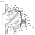
- a bearing device 11 according to a first embodiment of the present invention illustrated in the partial vertical cross-sectional view of Fig. 1 includes a bearing with an inner ring 12 rotating relative to an outer ring 13, a magnetic encoder 16, a protective cover 1, and a magnetic sensor C arranged at one axial end of the bearing, and a seal member 15 arranged at the other axial end of the bearing, and others.
- the bearing has the inner ring 12 with an inner ring track surface 12A on the outer peripheral surface, the outer ring 13 with an outer ring track surface 13A on the inner peripheral surface, and rolling elements 14, 14, ... rolling between the inner ring track surface 12A and the outer ring track surface 13A, and others.
- the magnetic encoder 16 has N and S poles alternately arranged at regular intervals in the circumferential direction, and is fixed to the inner ring 12 by a support member 17 positioned at the one axial end of the bearing.
- the protective cover 1 is attached to the outer ring 13 to seal the one axial end of the bearing and has a sensor holder part 8 holding the magnetic sensor C.
- the sensor holder part 8 has a base portion 8A holding the nut 10 and a step covering portion 8B covering the step D.
- the magnetic sensor C attached to the sensor holder part 8 of the protective cover 1 is opposed to the magnetic encoder 16 to detect the rotation of the magnetic encoder 16.
- the protective cover 1 is press-fitted into the outer ring 13 of the bearing in which the magnetic encoder 16 is fixed to the inner ring 12, whereby the protective cover 1 is axially positioned with respect to the magnetic encoder 16, and the magnetic sensor C is axially positioned and held with respect to the protective cover 1 by the sensor holder part 8 of the protective cover 1. Accordingly, an air gap between the magnetic sensor C and the magnetic encoder 16 is completely adjusted.
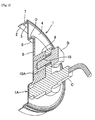
- the protective cover 1 has the cap part 1A and the nut 10 as a metallic component, a seal body 7 as an elastic component, and the sensor holder part 8 as a plastic component, and an adhesive intervenes between the cap part 1A and the sensor holder part 8.
- the protective cover 1 is an insert molded article that is formed with the cap part 1A and the nut 10 as inserts.
- the sensor holder part 8 is integrated by insert molding with the cap part 1A and the nut 10.
- the cap part 1A is a metallic component formed in a cup shape by pressing a non-magnetic steel plate, and is positioned at one axial end portion of the bearing and is press-fitted into the outer ring 13.
- the cap part 1A includes: a first cylindrical portion 2 that is press-fitted into the outer ring 13; a second cylindrical portion 3 that is smaller in diameter than the first cylindrical portion 2, connects to an end edge of the first cylindrical portion 2, and has an outer peripheral surface to which the seal body 7 is vulcanized and adhered; an annular portion 4 that connects to an end edge of the second cylindrical portion 3 and extends radially inward; a third cylindrical portion 5 that connects to an inner-side end edge of the annular portion 4 and extends axially; and a disc portion 6 that connects to an end edge of the third cylindrical portion 5.
- the disc portion 6 is a bottommost portion of the cap part 1A, and the disc portion 6 and the third cylindrical portion 5 extending axially from an outer edge of the disc portion 6 forms a step D.
- the seal body 7 is an elastic component formed from a synthetic rubber or the like.
- the synthetic rubbers for forming the seal body 7 can be one of rubbers such as nitrile rubber (NBR), hydrogenated nitrile rubber (HNBR), acrylic rubber (ACM), ethylene-acrylic rubber (AEM), fluorine rubber (FKM or FPM), and silicone rubber (VQM) or an appropriate blend of two or more of these rubbers.
- the sensor holder part 8 is a plastic component that holds the nut 10 screwed by an attachment bolt B for attachment of the magnetic sensor C.
- the plastic for forming the sensor holder part 8 is preferably any of polyamide resins such as aliphatic polyamide resins including polyamide 6, polyamide 66, polyamide 46, polyamide 11, polyamide 12, polyamide 610, and polyamide 612, or aromatic polyamide resins including polyamide 9T, polyamide 6T, and polyamide MXD6.
- polyamide resins such as aliphatic polyamide resins including polyamide 6, polyamide 66, polyamide 46, polyamide 11, polyamide 12, polyamide 610, and polyamide 612, or aromatic polyamide resins including polyamide 9T, polyamide 6T, and polyamide MXD6.
- thermoset resin adhesive for use in the present invention may be a phenol resin adhesive, an epoxy resin adhesive, or the like, for example.
- the phenol resin adhesive may be formed by dissolving a novolac-type phenol resin or a resol-type phenol resin, and a curing agent such as hexamethylenetetramine in a solvent such as methanol or methyl ethyl ketone, for example.
- the adhesive may be mixed with a novolac-type epoxy resin to improve adhesiveness.
- the epoxy resin adhesive may be a one-component epoxy adhesive as a liquid concentrate capable of being diluted with a solvent.
- the one-component epoxy adhesive is composed of an epoxy resin and a curing agent.
- the one-component epoxy adhesive may be further mixed as necessary with another epoxy compound for use as a reactive diluent, a curing accelerator for improving the thermal curing rate, an inorganic filler effective in improving heat resistance and curing distortion resistance, a cross-linking rubber fine particles for improving flexibility resulting in deformation under stress, and the like.
- the epoxy resin may be a bisphenol A-type epoxy resin, a bisphenol F-type epoxy resin, a bisphenol AD-type epoxy resin, a naphthalene-type epoxy resin, a biphenyl-type epoxy resin, a glycidyl amine-type epoxy resin, an alicyclic epoxy resin, a dicyclopentadiene-type epoxy resin, a phenol novolac-type epoxy resin, a polyester-modified epoxy resin, a silicon-modified epoxy resin, or the like, for example, although there is no particular limitation.
- the curing agent may be any of amine-based curing agents such as an aliphatic amine, an alicyclic amine, and an aromatic amine; polyamide-based curing agents; acid anhydride-based curing agents such as phthalic anhydride, methyltetrahydrophthalic anhydride, endo methylene-tetra-hydro phthalic anhydride, methyl endo methylene tetrahydrophthalic anhydride, methylhexahydrophthalic anhydride, or trimellitic anhydride; secondary or tertiary amines; imidazoles; 1,3-bis(hydrazinocarboethyl)-5-isopropylhydantoin; eicosanedioic acid dihydrazide; adipic acid dihydrazide; dicyandiamide; and 7,11-octadecadiene-1,18-dicarbohydrazide, for example, although there is no particular limitation.
- the reactive dilution agent may be alkyl monoglycidyl ether, alkyl diglycidyl ether, alkylphenol monoglycidyl ether, or the like, for example.
- the reactive dilution agent may be 2-ethylhexyl glycidyl ether, allyl glycidyl ether, phenyl glycidyl ether, t-butyl phenyl glycidyl ether, or the like, although there is no particular limitation.
- the curing accelerator is used to increase the rate of curing reaction in the case of using a curing agent such as acid anhydride or dicyandiamide.
- the curing accelerator may be any of imidazole compounds such as 1-cyanoethyl-2-ethyl-4-methylimidazole, 2-methylimidazole, 2-ethyl-4-methylimidazole, 2-undecylimidazole, and 2-phenylimidazole; carboxylic acids such as adipic acid; tertiary amines or tertiary amine salts such as dimethylbenzylamine and tris (dimethylaminomethyl) phenol; phosphines or phosphonium salts such as triphenylphosphine and tetraphenylphosphonium tetraphenyl borate; quaternary ammonium salts such as tetrabutylammonium bromide; and alkyl ureas such as 3-(3',
- the inorganic filler may be molten silica powder, crystalline silica, quartz glass powder, crystalline glass powder, glass fiber, alumina powder, talc, mica, aluminum powder, titanium oxide, silica titania, boron nitride, aluminum nitride, silicon nitride, magnesia, or magnesium silicate, for example. They may be used singly or in combination of two or more.
- the cross-linking rubber fine particle may be formed from vulcanized acrylonitrile-butadiene rubber, acrylic rubber, silicone rubber, urethane rubber, or the like having a carboxyl group in molecular chain, for example.
- the diameter of the cross-linking rubber fine particle may be 1 ⁇ m or less on the average, preferably about 30 to 200 nm as ultrafine particles, for example, although there is no particular limitation.
- the solvent contained in the epoxy resin adhesive may be any of aromatic hydrocarbons such as toluene and xylene, a mixture of the aromatic hydrocarbon and ketones and alcohols, and naphthenic hydrocarbons such as cyclohexane, for example, although there is no particular limitation.
- a manufacturing method of a protective cover having a sensor holder part according to the embodiment is a manufacturing method for the protective cover 1 having the cap part 1A as a metallic component press-fitted into the outer ring 13 and a plastic component forming the sensor holder part 8 holding the magnetic sensor C in a bearing device 11 illustrated in Fig.
- the manufacturing method including: an adhesive application step of applying a thermoset resin adhesive to a surface of the metallic component (the cap part 1A) including a joining surface relative to the plastic component (the sensor holder part 8); a natural drying step of evaporating a solvent contained in the adhesive by natural drying or a drying and solidification step of evaporating the solvent contained in the adhesive under a temperature condition at a temperature lower than a temperature at which the adhesive starts cross-linking reaction; an injection molding step of placing the metallic component having undergone the natural drying step or the drying and solidification step as an insert in an injection molding die and injecting a molten material for the plastic component from a gate into a cavity of the molding die; and a thermal curing step of applying thermal curing treatment to the adhesive at a temperature equal to or higher than the temperature at which the adhesive starts cross-linking reaction.
- thermoset resin adhesive A is applied to the surface of the cap part 1A in which the seal body 7 is vulcanized and adhered to the outer peripheral surface of the second cylindrical portion 3 including the joining surface relative to the sensor holder part 8 illustrated in Fig. 2 .
- the adhesive A may be applied to part of the surface of the cap part 1A (including the joining surface) using a brush, a roller, a spray, or the like.
- the surface of the cap part 1A may be immersed in the liquid thermoset resin adhesive A. Taking molding die contamination into consideration, however, it is preferred to apply the adhesive A to part of the surface of the cap part 1A (including the joining surface) so as not to extend beyond the joining surface relative to the sensor holder part 8, if possible.
- the temperature needs to cause no solidification or cross-linking curing reaction of the adhesive A, and may be room temperature, for example, although there is no particular limitation.
- the thickness or resin amount of the adhesive A to be applied to the cap part 1A needs to be sufficient for adhesion and fixation to the sensor holder part 8, although there is no particular limitation.
- the surface of the cap part 1A to which the adhesive A is applied is preferably subjected to roughening treatment or primer treatment from the viewpoint of improvement of an anchoring effect on the adhesive A.
- the roughening treatment may be blasting, chemical etching, chemical conversion, hairline processing, or the like.
- the roughness of the application surface of the cap part 1A having undergone the roughening treatment preferably falls within a range of Ra 0.5 to 2 ⁇ m.
- the roughness of the application surface can be measured under JIS B0601-1994.
- the primer may be a silane-based primer, a phenol-based primer, an epoxy-based primer, or the like.
- the adhesive A applied to the surface of the cap part 1A at the adhesive application step is naturally dried at room temperature to volatilize the solvent contained in the adhesive A.
- the adhesive A applied to the surface of the cap part 1A at the adhesive application step is placed under a temperature condition at a temperature lower than the temperature at which the adhesive A starts cross-linking reaction to volatilize the solvent contained in the adhesive, and dry and fix the adhesive A to the surface of the cap part 1A.
- the adhesive A has the property of starting cross-linking reaction and becoming cured when being heated to a predetermined temperature. Accordingly, in the present invention, the temperature at which the adhesive A starts cross-linking reaction and begins curing refers to "temperature at which the thermoset resin adhesive starts cross-linking reaction.”
- drying and solidification of the adhesive A refers to the state before the start of cross-linking reaction by heating, in which the solvent contained in the applied adhesive A is volatilized and the ingredients of the adhesive A are solidified.
- the solvent may be volatilized to the degree at which, when the surface of the applied adhesive A is directly touched with fingers, the adhesive A does not stick to the fingers, or to the degree that the solvent hardly remains.
- the adhesive A is preferably dried and solidified to the degree that the solvent hardly remains.
- the applied adhesive A changes lightly in color as being dried, and the degree of the drying and solidification can be checked by observing visually the state of color change.
- the adhesive A needs to be dried and solidified at a temperature lower than the temperature at which the adhesive A starts cross-linking reaction.
- the specific temperature for the drying and solidification can be decided as appropriate depending on the used adhesive A.
- the temperature is desirably adjusted to be lower than 110°C, preferably 25 to 105°C, from the viewpoint of short-time drying and solidification.
- the adhesive A may be dried and solidified with temperature increases in plural stages starting from a predetermined temperature, from the viewpoint of efficient drying and solidification.
- the time of drying and solidification can be decided as appropriate depending on the temperature of drying and solidification as far as the solvent in the adhesive A can be evaporated to solidify the solid content of the thermoset resin.
- the time of drying and solidification is preferably adjusted to 30 to 60 minutes or more from the viewpoint of stable drying and solidification at an industrial level.
- a gas adjusted to a predetermined temperature is blown onto the surface of the adhesive A applied to the cap part 1A.
- the cap part 1A with the adhesive A is left at rest at a predetermined temperature under reduced-pressure environment or is left at rest in a room at a predetermined adjusted temperature. The foregoing methods may be used in combination.
- the adhesive A is dried and solidified at a temperature lower than the temperature at which the adhesive A starts cross-linking reaction, which eliminates the need for semi-curing in which it is difficult to control the heating temperature and time.
- the joining force between the adhesive A and the plastic component can be enhanced by suppressing the decrease of reaction groups in the adhesive A for joining with the plastic material.
- the nut 10 is set as an insert in a support shaft 21 of a fixed die 18 and the cap part 1A as an insert is set in a movable die 19 as illustrated in the vertical cross-sectional view of Fig. 4 .
- the fixed die 18 and the movable die 19 are mounted and clamped in an injection molding machine, and a molten plastic material for forming the sensor holder part 8 is injected from a sprue through a gate 20 into cavities of the fixed die 18 and the movable die 19.
- the molten plastic material is cooled and solidified, and the movable die 19 is opened to remove the protective cover 1.
- the synthetic resin is entered into a peripheral groove 10A of the nut 10 to retain the nut 10.
- the protective cover 1 obtained at the injection molding step is subjected to thermal curing treatment at a temperature equal to or higher than the temperature at which the thermoset resin adhesive A starts cross-linking reaction.
- the temperature equal to or higher than the temperature at which the adhesive starts cross-linking reaction falls within a range of 110 to 180°C, for example.
- the thermal curing treatment may be performed with temperature increases in stages.
- the first temperature may be adjusted within a range of 110 to 140°C
- the second temperature may be adjusted within a range of 140 to 180°C.
- the upper limit of the temperature equal to or higher than the cross-linking reaction starting temperature may be higher than 180°C from the viewpoint of shortening the treatment time.
- concave portions 9, 9, ... may be formed in the outer peripheral surface of the third cylindrical portion 5 of the cap part 1A as illustrated in the partial vertical cross-sectional view of Fig. 5 .
- the plastic of the step covering portion 8B in the sensor holder part 8 enters into the concave portions 9, 9, ... to bring the cap part 1A and the sensor holder part 8 into mechanical bonding. This leads to improvement in the joint strength between the cap part 1A as the metallic component and the sensor holder part 8 as the plastic component.
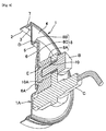
- the protective cover 1 may be configured without the step D of the cap part 1A and the step covering portion 8B of the sensor holder part 8 in the perspective vertical cross-sectional view of Fig. 2 as illustrated in the perspective vertical cross-sectional view of Fig. 6 , or the protective cover 1 may be configured with a cylindrical part 1B instead of the cap part 1A as the metallic component as illustrated in the perspective vertical cross-sectional view of Fig. 7 .
- the protective cover 1 may be configured such that a through hole 6A as illustrated in the perspective vertical cross-sectional view of Fig. 8 is formed in the disc portion 6 illustrated in the perspective vertical cross-sectional view of Fig. 2 or a through hole 6A as illustrated in the perspective vertical cross-sectional view of Fig. 9 is formed in the disc portion 6 illustrated in the perspective vertical cross-sectional view of Fig. 6 , and a wrap-around portion 8C extending radially outward on the inner surface side of the cup-shaped main part 1A through the through hole 6A in the disc portion 6 is formed on the sensor holder part 8.
- the protective covers 1 illustrated in Figs. 8 and 9 have an endless seal body E intervening between the cup-shaped main part 1A and the sensor holder part 8 around the through hole 6A.
- the protective covers 1 may not have the seal body E.
- thermoset resin adhesive intervenes between the cap part 1A or the cylindrical part 1B as the metallic component and the sensor holder part 8 as the plastic component.
- a dumbbell test specimen was fabricated to conduct evaluation test of adhesion strength. The results will be described below.
- a SUS430 metal plate for the metallic component was processed to fabricate a metallic component plate 23 (25 mm wide, 80 mm long, and 2 mm thick) illustrated in the schematic perspective view of Fig. 10 .
- thermoset resin adhesive was applied to the surface of the metallic component plate 23 on one side, with a width of about 10 mm relative to a longitudinal direction F. Then, the metallic component plate was placed and left at rest in a reaction container at temperatures of 25°C, 60°C, 90°C, 105°C, 120°C, and 150°C for 30 or 60 minutes to dry and completely remove organic solvents (methyl ethyl ketone, methyl isobutyl ketone, and methanol) in the thermoset resin adhesive, thereby forming the thermoset resin adhesive layer 26.
- organic solvents methyl ethyl ketone, methyl isobutyl ketone, and methanol
- the metallic component plate 23 was set in a predetermined insert molding die, and a molten plastic material (raw ingredient: PA12 or the like) at 270°C was injected into the molding die to mold a plastic component plate 24 almost the same in shape as the metallic component plate 23 illustrated in Fig. 10 .
- a molten plastic material raw ingredient: PA12 or the like
- the plastic component plate 24 was subjected to thermal curing treatment at 150°C which is higher than the cross-linking reaction starting temperature to cause the cross-linking reaction and curing reaction of the thermoset resin adhesive layer 26, thereby obtaining an adhesion strength evaluation dumbbell test specimen 22 illustrated in Fig. 10 .
- the obtained adhesion strength evaluation dumbbell test specimen 22 was subjected to tensile shear testing by a precision universal tester 25 at which the specimen was drawn in the directions of the both ends under JISK6850 test conditions to inspect the force by which the thermoset resin adhesive layer 26 was broken, and measured the separation strengths.
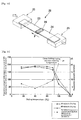
- Fig. 11 shows the measurement results of the separation strengths.
- the separation strengths in Fig. 11 are provided with respect to a score of 100 representing the value of separation strength at a drying temperature of 120°C for a drying time of 30 minutes.
- Fig. 11 also shows deviations in the separation strength resulting from the differences in the drying time by a two-dot chain line.
- the step of fabricating the adhesion strength evaluation dumbbell test specimen 22 conforms to manufacturing method of the protective cover having the sensor holder part of the present invention. Accordingly, the obtained separation strengths are considered to be equivalent to the separation strengths of the protective cover of the present invention fabricated in the same way.
- the inventors of the present invention have examined the cause of the reduction in separation strength.
- the separation strength decreased until the adhesion was lost at a drying temperature of 150°C. Accordingly, the inventors have recognized that there was a possibility that, when the drying temperature became higher, the adhesive caused curing reaction and decreased the reaction groups, thereby failing to join with the plastic.
- the inventors thus have dried the phenol-based thermoset resin adhesive applied to the surface of the metallic component under the temperature conditions: 1) air-drying at room temperature; 2) drying at 90°C for 10 minutes; and 3) baking at 150°C for 10 minutes, and inspected whether the adhesive could be removed by a methyl ethyl ketone (MEK) solvent under each of the conditions.
- MEK methyl ethyl ketone
- the adhesive generally dissolves in the MEK solvent, but the adhesive having caused cross-linking reaction and denautured due to thermal curing does not dissolve in the MEK solvent. Accordingly, whether the adhesive is thermally cured can be verified by checking whether the adhesive can be removed by the MEK solvent.
- the adhesive was removed by the MEK solvent in both of the air-dried specimen and the 90°C-dried specimen, whereas the adhesive was not removed by the MEK solvent in the 150°C-processed specimen and thus the adhesive was already cured. Since the processing time was short in the 150°C-processed specimen, the adhesive was not fully cured but semi-cured in the 150°C-processed specimen.
- thermoset resin adhesive applied to the surface of the metallic component.
- the separation strengths of the protective cover obtained by drying at 25 to 105°C were about 1.7 to 1.9 times higher than those obtained by drying at 120°C regardless of the processing time. Therefore, the joint strength of the adhesive could be significantly improved.
- the value of the deviation at the 120°C processing was about five times higher than that at the 60°C processing. This indicates that the cross-linking curing reaction became more active at higher temperatures, and the curing reaction state largely varied depending on the drying time.
- drying at as high temperature as 120°C could contribute to improvements in productivity such as shortening of the processing time, but it is difficult to control the drying temperature and the drying time, and it is inevitable that variations in the adhesion strength among the products will increase due to the fluctuations in temperature in a drying device and the differences in timing between introduction into and removal from the drying device at the time of mass processing.
- thermoset resin adhesive when dried at a drying temperature lower than the temperature at which the adhesive starts cross-linking reaction such as 25 to 105°C, the separation strength deviation becomes smaller to significantly suppress variations in the adhesion strength among the products in mass-processed batches and variations in the adhesion strength among the products in each of the batch.
- the tensile shear adhesion strengths of the adhesion strength evaluation dumbbell specimen at drying temperatures of 25 to 105°C were 8 to 11 N/mm 2 .
- the tensile shear adhesion strengths of the adhesion strength evaluation dumbbell specimen at drying temperatures of 120°C for a drying time of 30 minutes were generally less than 5N/mm 2 . Accordingly, the protective cover obtained by the manufacturing method of the present invention has been found to improve the adhesion strength more than the conventional ones.
Landscapes
- Engineering & Computer Science (AREA)
- Mechanical Engineering (AREA)
- General Engineering & Computer Science (AREA)
- Physics & Mathematics (AREA)
- General Physics & Mathematics (AREA)
- Manufacturing & Machinery (AREA)
- Chemical & Material Sciences (AREA)
- Organic Chemistry (AREA)
- Thermal Sciences (AREA)
- Injection Moulding Of Plastics Or The Like (AREA)
- Sealing Of Bearings (AREA)
- Lining Or Joining Of Plastics Or The Like (AREA)
Abstract
Description
- The present invention relates to a manufacturing method of a protective cover that is press-fitted into an outer ring of a bearing to cover a magnetic encoder and has a sensor holder part holding a magnetic sensor opposed to the magnetic encoder.
- An antilock brake system widely used in automobiles for efficient and safety braking without locking of wheels detects the rotation speeds of wheels by a rotation speed detector (wheel speed sensor), calculates the acceleration and the deceleration and estimates the vehicle speed and the slip ratio by a controller, and drives an actuator to control the brake fluid pressure based on the calculation and estimation results, for example.
- Bearing devices including such a rotation speed detector in a roller bearing for supporting automobile wheels (hub bearing) are also widely used. Such a bearing device may be structured such that a magnetic encoder having N poles and S poles alternately arranged at constant intervals in the circumferential direction is fitted to the inner ring of a bearing, a magnetic sensor for detecting the rotation of the magnetic encoder is attached to the outer ring of the bearing so as to be opposed to the magnetic encoder, and a protective cover covering the magnetic encoder from the inner side to protect the magnetic encoder is press-fitted into the inner end portion of the outer ring (for example, refer to Patent Document 1).
- The protective cover keeps the magnetic encoder from being hit by pebbles, mud water, or the like and prevents damage to the magnetic encoder. In addition, the protective cover eliminates the need for a seal member on the outer side of the magnetic encoder, which decreases a sliding resistance to reduce rotation torque of the bearing device.
- In addition, to eliminate a troublesome work of adjusting the air gap between the magnetic encoder and the magnetic sensor, the protective cover having the sensor holder part for holding the magnetic sensor may be configured such that a boss part composed of a synthetic resin is integrally joined to part of the bottom of a cap formed in a cup shape by press working on a non-magnetic steel plate, and a nut is integrally joined to the boss part to fix the magnetic sensor (for example, refer to Patent Document 2).
- Further, the protective cover having the sensor holder part may be formed by joining a metallic cylindrical member and a synthetic resin member into a cup shape with an adhesive (for example, refer to Patent Document 3).
- The protective cover having the sensor holder part as described in
Patent Documents - The protective covers with the sensor holder parts described in
Patent Documents - (1) Apply a thermoset resin adhesive to the surface (surface portion including a joinning surface relative to the boss part and the synthetic resin material) of the metallic cap as the metallic component in
Patent Document 2 or the metallic cylindrical member inPatent Document 3. - (2) Bake the adhesive material into a semi-cured state.
- (3) Set the metallic component as an insert in an injection molding die and injecting a molten plastic material into the molding die for injection molding.
- (4) Perform thermal curing treatment (secondary heating) to bring the adhesive into a fully cured state.
-
- Patent Document 1:
JP-A No. 2011-084265 - Patent Document 2:
JP-A No. 2013-117455 - Patent Document 3:
JP-A No. 2013-177928 - When the thermoset resin adhesive applied to the surface of the metallic component as an insert is brought into the semi-cured state, the resin is cured to some degree due to cross-linking reaction before contact with the molten plastic material and the reaction groups in the adhesive for joining with the molten plastic material decrease. Accordingly, the joining force of the adhesive and the plastic becomes weak with reduction in adhesion strength. In addition, when the adhesive is cured due to excessive cross-linking reaction resulting from variations in drying temperature and drying time, most of the remaining reaction groups decrease. This may lead to a sudden joining failure.
- In view of the foregoing circumstances, an object of the present invention is to provide a manufacturing method of a protective cover having a sensor holder part that has high adhesion strength between a metallic component and a plastic component and maintains high reliability over a long period.
- To solve the foregoing problem, a manufacturing method of a protective cover having a sensor holder part according to the present invention is a manufacturing method of a protective cover for use in a bearing device including: an inner ring with an inner ring track surface on an outer peripheral surface; an outer ring with an outer ring track surface on an inner peripheral surface; a bearing having a rolling element rolling between the inner ring track surface and the outer ring track surface; a magnetic encoder that is positioned at one axial end of the bearing, fixed to the inner ring, and has N and S poles alternately arranged at regular intervals in an circumferential direction; and a magnetic sensor that is opposed to the magnetic poles of the magnetic encoder to detect rotation of the magnetic encoder, the protective cover having a metallic component press-fitted into the outer ring and a plastic component forming a sensor holder part holding the magnetic sensor, wherein the manufacturing method comprises: an adhesive application step of applying a thermoset resin adhesive to a surface of the metallic component including a joining surface relative to the plastic component; a natural drying step of evaporating a solvent contained in the adhesive by natural drying or a drying and solidification step of evaporating the solvent contained in the adhesive under a temperature condition at a temperature lower than a temperature at which the adhesive starts cross-linking reaction; an injection molding step of placing the metallic component having undergone the natural drying step or the drying and solidification step as an insert in an injection molding die and injecting a molten material for the plastic component from a gate into a cavity of the molding die; and a thermal curing step of applying thermal curing treatment to the adhesive at a temperature equal to or higher than the temperature at which the adhesive starts cross-linking reaction.
- According to the manufacturing method, the injection molding step is performed without bringing the thermoset resin adhesive into the semi-cured state in which it is hard to control the heating temperature and the heating time and the adhesive becomes unstable. Accordingly, it is possible to reduce variations in adhesion strength between the metallic component and the plastic component in the protective cover having the sensor holder part.
- Moreover, the adhesive is not cured due to cross-linking reaction before contact with the molten material for the plastic component in the injection molding step, and the joining force of the adhesive and the plastic component is not weaken. This improves the adhesion strength of the metallic component and the plastic component.
- According to the manufacturing method for the protective cover having the sensor holder part of the present invention, it is possible to produce advantageous effects of obtaining high adhesion strength between the metallic component and the plastic component and maintaining high reliability over a long period of time in the protective cover having the sensor holder part manufactured by insert molding.
-
-
Fig. 1 is a partial vertical cross-sectional view of a bearing device including a protective cover having a sensor holder part; -
Fig. 2 is a perspective vertical cross-sectional view of the protective cover having the sensor holder part to which the magnetic sensor is attached; -
Fig. 3 is a vertical cross-sectional view showing an application range of a thermoset resin adhesive on a cap part in which the thickness of the thermoset resin adhesive is exaggerated for the sake of visibility of the drawing; -
Fig. 4 is a vertical cross-sectional view of an example of an injection molding die; -
Fig. 5 is a partial vertical cross-sectional view of a protective cover having a sensor holder part in another embodiment to which a magnetic sensor is attached; -
Fig. 6 is a perspective vertical cross-sectional view of a protective cover having a sensor holder part in another embodiment to which a magnetic sensor is attached; -
Fig. 7 is a perspective vertical cross-sectional view of a protective cover having a sensor holder part in another embodiment to which a magnetic sensor is attached; -
Fig. 8 is a perspective vertical cross-sectional view of a protective cover having a sensor holder part in another embodiment to which a magnetic sensor is attached; -
Fig. 9 is a perspective vertical cross-sectional view of a protective cover having a sensor holder part in another embodiment to which a magnetic sensor is attached; -
Fig. 10 is a schematic perspective view of a Dumbbell test specimen for adhesion strength evaluation; and -
Fig. 11 is a graph that illustrates test results showing the relationship between the drying temperature and the separation strength using the Dumbbell test specimen for adhesion strength evaluation illustrated inFig. 10 , and separation strength test results using the Dumbbell test specimen in which thermal curing treatment was applied to a thermoset resin adhesive layer at a temperature equal to or higher than a cross-linking reaction start temperature (150°C) to occur cross-linking reaction and curing reaction. - Next, embodiments of the present invention will be described in detail with reference to the accompanying drawings. However, the present invention is not limited to the embodiments illustrated in the accompanying drawings but includes any other embodiments satisfying the requirements described in the claims.
- A
bearing device 11 according to a first embodiment of the present invention illustrated in the partial vertical cross-sectional view ofFig. 1 includes a bearing with aninner ring 12 rotating relative to anouter ring 13, amagnetic encoder 16, aprotective cover 1, and a magnetic sensor C arranged at one axial end of the bearing, and aseal member 15 arranged at the other axial end of the bearing, and others. - The bearing has the
inner ring 12 with an innerring track surface 12A on the outer peripheral surface, theouter ring 13 with an outerring track surface 13A on the inner peripheral surface, androlling elements ring track surface 12A and the outerring track surface 13A, and others. - The
magnetic encoder 16 has N and S poles alternately arranged at regular intervals in the circumferential direction, and is fixed to theinner ring 12 by asupport member 17 positioned at the one axial end of the bearing. - The
protective cover 1 is attached to theouter ring 13 to seal the one axial end of the bearing and has asensor holder part 8 holding the magnetic sensor C. - The
sensor holder part 8 has abase portion 8A holding thenut 10 and astep covering portion 8B covering the step D. - The magnetic sensor C attached to the
sensor holder part 8 of theprotective cover 1 is opposed to themagnetic encoder 16 to detect the rotation of themagnetic encoder 16. - In the
bearing device 11 illustrated inFig. 1 , theprotective cover 1 is press-fitted into theouter ring 13 of the bearing in which themagnetic encoder 16 is fixed to theinner ring 12, whereby theprotective cover 1 is axially positioned with respect to themagnetic encoder 16, and the magnetic sensor C is axially positioned and held with respect to theprotective cover 1 by thesensor holder part 8 of theprotective cover 1. Accordingly, an air gap between the magnetic sensor C and themagnetic encoder 16 is completely adjusted. - This eliminates a troublesome work of adjusting the air gap between the
magnetic encoder 16 and the magnetic sensor C. - As illustrated in the partial vertical cross-sectional view of
Fig. 1 and the perspective vertical cross-sectional view ofFig. 2 , theprotective cover 1 has thecap part 1A and thenut 10 as a metallic component, aseal body 7 as an elastic component, and thesensor holder part 8 as a plastic component, and an adhesive intervenes between thecap part 1A and thesensor holder part 8. - The
protective cover 1 is an insert molded article that is formed with thecap part 1A and thenut 10 as inserts. - Accordingly, the
sensor holder part 8 is integrated by insert molding with thecap part 1A and thenut 10. - The
cap part 1A is a metallic component formed in a cup shape by pressing a non-magnetic steel plate, and is positioned at one axial end portion of the bearing and is press-fitted into theouter ring 13. - The
cap part 1A includes: a firstcylindrical portion 2 that is press-fitted into theouter ring 13; a secondcylindrical portion 3 that is smaller in diameter than the firstcylindrical portion 2, connects to an end edge of the firstcylindrical portion 2, and has an outer peripheral surface to which theseal body 7 is vulcanized and adhered; anannular portion 4 that connects to an end edge of the secondcylindrical portion 3 and extends radially inward; a thirdcylindrical portion 5 that connects to an inner-side end edge of theannular portion 4 and extends axially; and adisc portion 6 that connects to an end edge of the thirdcylindrical portion 5. - The
disc portion 6 is a bottommost portion of thecap part 1A, and thedisc portion 6 and the thirdcylindrical portion 5 extending axially from an outer edge of thedisc portion 6 forms a step D. - The
seal body 7 is an elastic component formed from a synthetic rubber or the like. The synthetic rubbers for forming theseal body 7 can be one of rubbers such as nitrile rubber (NBR), hydrogenated nitrile rubber (HNBR), acrylic rubber (ACM), ethylene-acrylic rubber (AEM), fluorine rubber (FKM or FPM), and silicone rubber (VQM) or an appropriate blend of two or more of these rubbers. - The
sensor holder part 8 is a plastic component that holds thenut 10 screwed by an attachment bolt B for attachment of the magnetic sensor C. - The plastic for forming the
sensor holder part 8 is preferably any of polyamide resins such as aliphatic polyamideresins including polyamide 6, polyamide 66, polyamide 46,polyamide 11,polyamide 12, polyamide 610, and polyamide 612, or aromatic polyamide resins including polyamide 9T, polyamide 6T, and polyamide MXD6. - The adhesive intervening between the
cap part 1A and thesensor holder part 8 is a thermoset resin adhesive. The thermoset resin adhesive for use in the present invention may be a phenol resin adhesive, an epoxy resin adhesive, or the like, for example. - The phenol resin adhesive may be formed by dissolving a novolac-type phenol resin or a resol-type phenol resin, and a curing agent such as hexamethylenetetramine in a solvent such as methanol or methyl ethyl ketone, for example. In addition, the adhesive may be mixed with a novolac-type epoxy resin to improve adhesiveness.
- The epoxy resin adhesive may be a one-component epoxy adhesive as a liquid concentrate capable of being diluted with a solvent. The one-component epoxy adhesive is composed of an epoxy resin and a curing agent. The one-component epoxy adhesive may be further mixed as necessary with another epoxy compound for use as a reactive diluent, a curing accelerator for improving the thermal curing rate, an inorganic filler effective in improving heat resistance and curing distortion resistance, a cross-linking rubber fine particles for improving flexibility resulting in deformation under stress, and the like.
- The epoxy resin may be a bisphenol A-type epoxy resin, a bisphenol F-type epoxy resin, a bisphenol AD-type epoxy resin, a naphthalene-type epoxy resin, a biphenyl-type epoxy resin, a glycidyl amine-type epoxy resin, an alicyclic epoxy resin, a dicyclopentadiene-type epoxy resin, a phenol novolac-type epoxy resin, a polyester-modified epoxy resin, a silicon-modified epoxy resin, or the like, for example, although there is no particular limitation.
- The curing agent may be any of amine-based curing agents such as an aliphatic amine, an alicyclic amine, and an aromatic amine; polyamide-based curing agents; acid anhydride-based curing agents such as phthalic anhydride, methyltetrahydrophthalic anhydride, endo methylene-tetra-hydro phthalic anhydride, methyl endo methylene tetrahydrophthalic anhydride, methylhexahydrophthalic anhydride, or trimellitic anhydride; secondary or tertiary amines; imidazoles; 1,3-bis(hydrazinocarboethyl)-5-isopropylhydantoin; eicosanedioic acid dihydrazide; adipic acid dihydrazide; dicyandiamide; and 7,11-octadecadiene-1,18-dicarbohydrazide, for example, although there is no particular limitation.
- The reactive dilution agent may be alkyl monoglycidyl ether, alkyl diglycidyl ether, alkylphenol monoglycidyl ether, or the like, for example. Specifically, the reactive dilution agent may be 2-ethylhexyl glycidyl ether, allyl glycidyl ether, phenyl glycidyl ether, t-butyl phenyl glycidyl ether, or the like, although there is no particular limitation.
- The curing accelerator is used to increase the rate of curing reaction in the case of using a curing agent such as acid anhydride or dicyandiamide. The curing accelerator may be any of imidazole compounds such as 1-cyanoethyl-2-ethyl-4-methylimidazole, 2-methylimidazole, 2-ethyl-4-methylimidazole, 2-undecylimidazole, and 2-phenylimidazole; carboxylic acids such as adipic acid; tertiary amines or tertiary amine salts such as dimethylbenzylamine and tris (dimethylaminomethyl) phenol; phosphines or phosphonium salts such as triphenylphosphine and tetraphenylphosphonium tetraphenyl borate; quaternary ammonium salts such as tetrabutylammonium bromide; and alkyl ureas such as 3-(3',4'-dichlorophenyl)-1,1-dimethyl urea, for example, although there is no particular limitation.
- The inorganic filler may be molten silica powder, crystalline silica, quartz glass powder, crystalline glass powder, glass fiber, alumina powder, talc, mica, aluminum powder, titanium oxide, silica titania, boron nitride, aluminum nitride, silicon nitride, magnesia, or magnesium silicate, for example. They may be used singly or in combination of two or more.
- The cross-linking rubber fine particle may be formed from vulcanized acrylonitrile-butadiene rubber, acrylic rubber, silicone rubber, urethane rubber, or the like having a carboxyl group in molecular chain, for example. The diameter of the cross-linking rubber fine particle may be 1 µm or less on the average, preferably about 30 to 200 nm as ultrafine particles, for example, although there is no particular limitation.
- The solvent contained in the epoxy resin adhesive may be any of aromatic hydrocarbons such as toluene and xylene, a mixture of the aromatic hydrocarbon and ketones and alcohols, and naphthenic hydrocarbons such as cyclohexane, for example, although there is no particular limitation.
- A manufacturing method of a protective cover having a sensor holder part according to the embodiment is a manufacturing method for the
protective cover 1 having thecap part 1A as a metallic component press-fitted into theouter ring 13 and a plastic component forming thesensor holder part 8 holding the magnetic sensor C in abearing device 11 illustrated inFig. 1 , wherein the manufacturing method including: an adhesive application step of applying a thermoset resin adhesive to a surface of the metallic component (thecap part 1A) including a joining surface relative to the plastic component (the sensor holder part 8); a natural drying step of evaporating a solvent contained in the adhesive by natural drying or a drying and solidification step of evaporating the solvent contained in the adhesive under a temperature condition at a temperature lower than a temperature at which the adhesive starts cross-linking reaction; an injection molding step of placing the metallic component having undergone the natural drying step or the drying and solidification step as an insert in an injection molding die and injecting a molten material for the plastic component from a gate into a cavity of the molding die; and a thermal curing step of applying thermal curing treatment to the adhesive at a temperature equal to or higher than the temperature at which the adhesive starts cross-linking reaction. - At this step, as illustrated in the vertical cross-sectional view of
Fig. 3 , a thermoset resin adhesive A is applied to the surface of thecap part 1A in which theseal body 7 is vulcanized and adhered to the outer peripheral surface of the secondcylindrical portion 3 including the joining surface relative to thesensor holder part 8 illustrated inFig. 2 . - As a method of applying the thermoset resin adhesive A to the surface of the
cap part 1A including the joining surface relative to thesensor holder part 8, the adhesive A may be applied to part of the surface of thecap part 1A (including the joining surface) using a brush, a roller, a spray, or the like. - Alternatively, the surface of the
cap part 1A may be immersed in the liquid thermoset resin adhesive A. Taking molding die contamination into consideration, however, it is preferred to apply the adhesive A to part of the surface of thecap part 1A (including the joining surface) so as not to extend beyond the joining surface relative to thesensor holder part 8, if possible. - As for temperature conditions for applying the thermoset resin adhesive A to the
cap part 1A, the temperature needs to cause no solidification or cross-linking curing reaction of the adhesive A, and may be room temperature, for example, although there is no particular limitation. - The thickness or resin amount of the adhesive A to be applied to the
cap part 1A needs to be sufficient for adhesion and fixation to thesensor holder part 8, although there is no particular limitation. - The surface of the
cap part 1A to which the adhesive A is applied is preferably subjected to roughening treatment or primer treatment from the viewpoint of improvement of an anchoring effect on the adhesive A. - The roughening treatment may be blasting, chemical etching, chemical conversion, hairline processing, or the like.
- The roughness of the application surface of the
cap part 1A having undergone the roughening treatment preferably falls within a range of Ra 0.5 to 2 µm. - The roughness of the application surface can be measured under JIS B0601-1994.
- The primer may be a silane-based primer, a phenol-based primer, an epoxy-based primer, or the like.
- At this step, the adhesive A applied to the surface of the
cap part 1A at the adhesive application step is naturally dried at room temperature to volatilize the solvent contained in the adhesive A. - At this step, the adhesive A applied to the surface of the
cap part 1A at the adhesive application step is placed under a temperature condition at a temperature lower than the temperature at which the adhesive A starts cross-linking reaction to volatilize the solvent contained in the adhesive, and dry and fix the adhesive A to the surface of thecap part 1A. - The adhesive A has the property of starting cross-linking reaction and becoming cured when being heated to a predetermined temperature. Accordingly, in the present invention, the temperature at which the adhesive A starts cross-linking reaction and begins curing refers to "temperature at which the thermoset resin adhesive starts cross-linking reaction."
- The "drying and solidification" of the adhesive A here refers to the state before the start of cross-linking reaction by heating, in which the solvent contained in the applied adhesive A is volatilized and the ingredients of the adhesive A are solidified.
- There is no particular limitation on the degree of evaporation of the solvent at the time of drying and solidification. The solvent may be volatilized to the degree at which, when the surface of the applied adhesive A is directly touched with fingers, the adhesive A does not stick to the fingers, or to the degree that the solvent hardly remains. In particular, from the viewpoint of ease of adhesion to the plastic, the adhesive A is preferably dried and solidified to the degree that the solvent hardly remains. The applied adhesive A changes lightly in color as being dried, and the degree of the drying and solidification can be checked by observing visually the state of color change.
- The adhesive A needs to be dried and solidified at a temperature lower than the temperature at which the adhesive A starts cross-linking reaction. The specific temperature for the drying and solidification can be decided as appropriate depending on the used adhesive A. For example, in the case of using a phenol resin adhesive, the temperature is desirably adjusted to be lower than 110°C, preferably 25 to 105°C, from the viewpoint of short-time drying and solidification.
- Alternatively, the adhesive A may be dried and solidified with temperature increases in plural stages starting from a predetermined temperature, from the viewpoint of efficient drying and solidification.
- In this case, there is no particular limitation on the difference between the first temperature and the second temperature, or the like.
- The time of drying and solidification can be decided as appropriate depending on the temperature of drying and solidification as far as the solvent in the adhesive A can be evaporated to solidify the solid content of the thermoset resin. For example, the time of drying and solidification is preferably adjusted to 30 to 60 minutes or more from the viewpoint of stable drying and solidification at an industrial level.
- As a means for drying and solidification, for example, there is a method by which a gas adjusted to a predetermined temperature is blown onto the surface of the adhesive A applied to the
cap part 1A. In addition, there is another method by which thecap part 1A with the adhesive A is left at rest at a predetermined temperature under reduced-pressure environment or is left at rest in a room at a predetermined adjusted temperature. The foregoing methods may be used in combination. - In the present invention, the adhesive A is dried and solidified at a temperature lower than the temperature at which the adhesive A starts cross-linking reaction, which eliminates the need for semi-curing in which it is difficult to control the heating temperature and time. In addition, the joining force between the adhesive A and the plastic component can be enhanced by suppressing the decrease of reaction groups in the adhesive A for joining with the plastic material.
- The
cap part 1A as an insert having undergone the adhesive application step and the natural drying step or the drying and solidification step is used. - At this step, the
nut 10 is set as an insert in asupport shaft 21 of a fixeddie 18 and thecap part 1A as an insert is set in amovable die 19 as illustrated in the vertical cross-sectional view ofFig. 4 . - Next, the fixed
die 18 and themovable die 19 are mounted and clamped in an injection molding machine, and a molten plastic material for forming thesensor holder part 8 is injected from a sprue through agate 20 into cavities of the fixeddie 18 and themovable die 19. - Then, the molten plastic material is cooled and solidified, and the
movable die 19 is opened to remove theprotective cover 1. - In the
protective cover 1 formed by insert molding as described above (seeFigs. 1 and2 ), the synthetic resin is entered into aperipheral groove 10A of thenut 10 to retain thenut 10. - At this step, the
protective cover 1 obtained at the injection molding step is subjected to thermal curing treatment at a temperature equal to or higher than the temperature at which the thermoset resin adhesive A starts cross-linking reaction. - The temperature equal to or higher than the temperature at which the adhesive starts cross-linking reaction falls within a range of 110 to 180°C, for example.
- The thermal curing treatment may be performed with temperature increases in stages. For example, the first temperature may be adjusted within a range of 110 to 140°C, and the second temperature may be adjusted within a range of 140 to 180°C. The upper limit of the temperature equal to or higher than the cross-linking reaction starting temperature may be higher than 180°C from the viewpoint of shortening the treatment time.
- After the foregoing steps, the
protective cover 1 is completed. - In the
protective cover 1 described above as illustrated in the partial vertical cross-sectional view ofFig. 1 and the perspective vertical cross-sectional view ofFig. 2 ,concave portions cylindrical portion 5 of thecap part 1A as illustrated in the partial vertical cross-sectional view ofFig. 5 . - By forming the
cap part 1A in such a shape, the plastic of thestep covering portion 8B in thesensor holder part 8 enters into theconcave portions cap part 1A and thesensor holder part 8 into mechanical bonding. This leads to improvement in the joint strength between thecap part 1A as the metallic component and thesensor holder part 8 as the plastic component. - In addition, the
protective cover 1 may be configured without the step D of thecap part 1A and thestep covering portion 8B of thesensor holder part 8 in the perspective vertical cross-sectional view ofFig. 2 as illustrated in the perspective vertical cross-sectional view ofFig. 6 , or theprotective cover 1 may be configured with acylindrical part 1B instead of thecap part 1A as the metallic component as illustrated in the perspective vertical cross-sectional view ofFig. 7 . - Further, the
protective cover 1 may be configured such that a throughhole 6A as illustrated in the perspective vertical cross-sectional view ofFig. 8 is formed in thedisc portion 6 illustrated in the perspective vertical cross-sectional view ofFig. 2 or a throughhole 6A as illustrated in the perspective vertical cross-sectional view ofFig. 9 is formed in thedisc portion 6 illustrated in the perspective vertical cross-sectional view ofFig. 6 , and a wrap-around portion 8C extending radially outward on the inner surface side of the cup-shapedmain part 1A through the throughhole 6A in thedisc portion 6 is formed on thesensor holder part 8. - The protective covers 1 illustrated in
Figs. 8 and9 have an endless seal body E intervening between the cup-shapedmain part 1A and thesensor holder part 8 around the throughhole 6A. The protective covers 1 may not have the seal body E. - However, in either of the
protective covers 1, the thermoset resin adhesive intervenes between thecap part 1A or thecylindrical part 1B as the metallic component and thesensor holder part 8 as the plastic component. - A dumbbell test specimen was fabricated to conduct evaluation test of adhesion strength. The results will be described below.
- First, a SUS430 metal plate for the metallic component was processed to fabricate a metallic component plate 23 (25 mm wide, 80 mm long, and 2 mm thick) illustrated in the schematic perspective view of
Fig. 10 . - Next, a phenol-based thermoset resin adhesive was applied to the surface of the
metallic component plate 23 on one side, with a width of about 10 mm relative to a longitudinal direction F. Then, the metallic component plate was placed and left at rest in a reaction container at temperatures of 25°C, 60°C, 90°C, 105°C, 120°C, and 150°C for 30 or 60 minutes to dry and completely remove organic solvents (methyl ethyl ketone, methyl isobutyl ketone, and methanol) in the thermoset resin adhesive, thereby forming the thermosetresin adhesive layer 26. - Next, the
metallic component plate 23 was set in a predetermined insert molding die, and a molten plastic material (raw ingredient: PA12 or the like) at 270°C was injected into the molding die to mold aplastic component plate 24 almost the same in shape as themetallic component plate 23 illustrated inFig. 10 . - Next, the
plastic component plate 24 was subjected to thermal curing treatment at 150°C which is higher than the cross-linking reaction starting temperature to cause the cross-linking reaction and curing reaction of the thermosetresin adhesive layer 26, thereby obtaining an adhesion strength evaluationdumbbell test specimen 22 illustrated inFig. 10 . - The obtained adhesion strength evaluation
dumbbell test specimen 22 was subjected to tensile shear testing by a precisionuniversal tester 25 at which the specimen was drawn in the directions of the both ends under JISK6850 test conditions to inspect the force by which the thermosetresin adhesive layer 26 was broken, and measured the separation strengths.Fig. 11 shows the measurement results of the separation strengths. The separation strengths inFig. 11 are provided with respect to a score of 100 representing the value of separation strength at a drying temperature of 120°C for a drying time of 30 minutes.Fig. 11 also shows deviations in the separation strength resulting from the differences in the drying time by a two-dot chain line. - The step of fabricating the adhesion strength evaluation
dumbbell test specimen 22 conforms to manufacturing method of the protective cover having the sensor holder part of the present invention. Accordingly, the obtained separation strengths are considered to be equivalent to the separation strengths of the protective cover of the present invention fabricated in the same way. - It can be seen from the results shown in
Fig. 11 that the separation strength started to become lower when the drying temperature exceeded about 105°C, and decreased significantly at a drying temperature of 120°C or so. - The inventors of the present invention have examined the cause of the reduction in separation strength. The separation strength decreased until the adhesion was lost at a drying temperature of 150°C. Accordingly, the inventors have recognized that there was a possibility that, when the drying temperature became higher, the adhesive caused curing reaction and decreased the reaction groups, thereby failing to join with the plastic.
- The inventors thus have dried the phenol-based thermoset resin adhesive applied to the surface of the metallic component under the temperature conditions: 1) air-drying at room temperature; 2) drying at 90°C for 10 minutes; and 3) baking at 150°C for 10 minutes, and inspected whether the adhesive could be removed by a methyl ethyl ketone (MEK) solvent under each of the conditions. The adhesive generally dissolves in the MEK solvent, but the adhesive having caused cross-linking reaction and denautured due to thermal curing does not dissolve in the MEK solvent. Accordingly, whether the adhesive is thermally cured can be verified by checking whether the adhesive can be removed by the MEK solvent.
- As a result, the adhesive was removed by the MEK solvent in both of the air-dried specimen and the 90°C-dried specimen, whereas the adhesive was not removed by the MEK solvent in the 150°C-processed specimen and thus the adhesive was already cured. Since the processing time was short in the 150°C-processed specimen, the adhesive was not fully cured but semi-cured in the 150°C-processed specimen.
- From the foregoing findings, it is estimated that the phenomenon of reduction in the separation strength at 105°C or so was caused by thermal curing of the thermoset resin adhesive applied to the surface of the metallic component.
- In fact, as seen from the results shown in
Fig. 11 , the separation strengths of the protective cover obtained by drying at 25 to 105°C were about 1.7 to 1.9 times higher than those obtained by drying at 120°C regardless of the processing time. Therefore, the joint strength of the adhesive could be significantly improved. - In addition, in the case of drying at 25 to 105°C, the temperature environment became lower than the case of drying at a high temperature adjusted to 120°C or the like, which produces the advantage of facilitating stable mass processing.
- Further, it can be seen from the results of
Fig. 11 that the separation strength deviation became larger at drying temperatures higher than 105°C, and the influence of the drying temperature on the change in strength became larger. - Specifically, the value of the deviation at the 120°C processing was about five times higher than that at the 60°C processing. This indicates that the cross-linking curing reaction became more active at higher temperatures, and the curing reaction state largely varied depending on the drying time.
- That is, it is suggested that drying at as high temperature as 120°C could contribute to improvements in productivity such as shortening of the processing time, but it is difficult to control the drying temperature and the drying time, and it is inevitable that variations in the adhesion strength among the products will increase due to the fluctuations in temperature in a drying device and the differences in timing between introduction into and removal from the drying device at the time of mass processing.
- In contrast, when the thermoset resin adhesive is dried at a drying temperature lower than the temperature at which the adhesive starts cross-linking reaction such as 25 to 105°C, the separation strength deviation becomes smaller to significantly suppress variations in the adhesion strength among the products in mass-processed batches and variations in the adhesion strength among the products in each of the batch.
- The tensile shear adhesion strengths of the adhesion strength evaluation dumbbell specimen at drying temperatures of 25 to 105°C were 8 to 11 N/mm2.
- Meanwhile, the tensile shear adhesion strengths of the adhesion strength evaluation dumbbell specimen at drying temperatures of 120°C for a drying time of 30 minutes were generally less than 5N/mm2. Accordingly, the protective cover obtained by the manufacturing method of the present invention has been found to improve the adhesion strength more than the conventional ones.
-
- 1
- Protective cover
- 1A
- Cap part (metallic component)
- 1B
- Cylindrical part (metallic component)
- 2
- First cylindrical portion
- 3
- Second cylindrical portion
- 4
- Annular portion
- 5
- Third cylindrical portion
- 6
- Disc portion
- 6A
- Through hole
- 7
- Seal body (elastic component)
- 8
- Sensor holder part (plastic component)
- 8A
- Base portion
- 8B
- Step covering portion
- 8C
- Wrap-around portion
- 9
- Concave portion
- 10
- Nut
- 10A
- Peripheral groove
- 11
- Bearing device
- 12
- Inner ring
- 12A
- Inner ring track surface
- 13
- Outer ring
- 13A
- Outer ring track surface
- 14
- Rolling element
- 15
- Seal member
- 16
- Magnetic encoder
- 17
- Support member
- 18
- Fixed die
- 19
- Movable die
- 20
- Gate
- 21
- Support shaft
- 22
- Adhesion strength evaluation dumbbell test specimen
- 23
- Metallic component plate
- 24
- Plastic component plate
- 25
- Precision universal tester
- 26
- Thermoset resin adhesive layer
- A
- Thermoset resin adhesive
- B
- Attachment bolt
- C
- Magnetic sensor
- D
- Step
- E
- Seal body
- F
- Longitudinal direction
Claims (1)
- A manufacturing method of a protective cover for use in a bearing device including: an inner ring with an inner ring track surface on an outer peripheral surface; an outer ring with an outer ring track surface on an inner peripheral surface; a bearing having a rolling element rolling between the inner ring track surface and the outer ring track surface; a magnetic encoder that is positioned at one axial end of the bearing, fixed to the inner ring, and has N and S poles alternately arranged at regular intervals in an circumferential direction; and a magnetic sensor that is opposed to the magnetic poles of the magnetic encoder to detect rotation of the magnetic encoder, the protective cover having a metallic component press-fitted into the outer ring and a plastic component forming a sensor holder part holding the magnetic sensor wherein
the manufacturing method comprises:an adhesive application step of applying a thermoset resin adhesive to a surface of the metallic component including a joining surface relative to the plastic component;a natural drying step of evaporating a solvent contained in the adhesive by natural drying or a drying and solidification step of evaporating the solvent contained in the adhesive under a temperature condition at a temperature lower than a temperature at which the adhesive starts cross-linking reaction;an injection molding step of placing the metallic component having undergone the natural drying step or the drying and solidification step as an insert in an injection molding die and injecting a molten material for the plastic component from a gate into a cavity of the molding die; anda thermal curing step of applying thermal curing treatment to the adhesive at a temperature equal to or higher than the temperature at which the adhesive starts cross-linking reaction.
Applications Claiming Priority (1)
| Application Number | Priority Date | Filing Date | Title |
|---|---|---|---|
| JP2015170340A JP2017047542A (en) | 2015-08-31 | 2015-08-31 | Method for manufacturing protective cover having sensor holder |
Publications (1)
| Publication Number | Publication Date |
|---|---|
| EP3135451A1 true EP3135451A1 (en) | 2017-03-01 |
Family
ID=56883530
Family Applications (1)
| Application Number | Title | Priority Date | Filing Date |
|---|---|---|---|
| EP16183928.7A Withdrawn EP3135451A1 (en) | 2015-08-31 | 2016-08-12 | Manufacturing method of a protective cover for a bearing device having a sensor holder part |
Country Status (4)
| Country | Link |
|---|---|
| US (1) | US20170057136A1 (en) |
| EP (1) | EP3135451A1 (en) |
| JP (1) | JP2017047542A (en) |
| CN (1) | CN106476297A (en) |
Cited By (1)
| Publication number | Priority date | Publication date | Assignee | Title |
|---|---|---|---|---|
| CN113825609A (en) * | 2019-05-24 | 2021-12-21 | Dic株式会社 | Adhesive sheet, article, and method of making the article |
Families Citing this family (11)
| Publication number | Priority date | Publication date | Assignee | Title |
|---|---|---|---|---|
| US11155012B2 (en) | 2016-01-26 | 2021-10-26 | Henniges Automotive Sealing Systems North America, Inc. | Method of manufacturing a seal assembly for a vehicle |
| JP6294394B2 (en) * | 2016-06-28 | 2018-03-14 | Ntn株式会社 | Wheel bearing device |
| US11117785B2 (en) * | 2016-12-13 | 2021-09-14 | Mitsubishi Electric Corporation | Wire rope flaw detector |
| US10723050B2 (en) * | 2017-11-29 | 2020-07-28 | Henniges Automotive Sealing Systems North America, Inc. | Method of manufacturing a window seal assembly with a molded bracket |
| JP7206880B2 (en) * | 2018-03-26 | 2023-01-18 | 中西金属工業株式会社 | Protective cover having sensor holder portion, bearing device provided with said protective cover, and method for manufacturing protective cover having sensor holder portion |
| JP7040210B2 (en) * | 2018-03-28 | 2022-03-23 | 中西金属工業株式会社 | A method for manufacturing a protective cover having a sensor holder portion, a bearing device provided with the protective cover, and a protective cover having a sensor holder portion. |
| DE102019212747A1 (en) * | 2018-09-10 | 2020-04-30 | Aktiebolaget Skf | Sealing device for a wheel bearing unit |
| JP2020122492A (en) * | 2019-01-29 | 2020-08-13 | 中西金属工業株式会社 | Manufacturing method of slinger for use in rotation seal and rotation seal |
| JP7200075B2 (en) * | 2019-09-26 | 2023-01-06 | 住友理工株式会社 | VEHICLE RESIN MODULE AND METHOD OF PRODUCING VEHICLE RESIN MODULE |
| CN112123803B (en) * | 2020-08-05 | 2023-02-14 | 安徽中鼎橡塑制品有限公司 | Sensor cover and manufacturing method thereof |
| CN114801226B (en) * | 2022-03-22 | 2024-02-06 | 广东诗妃化妆品有限公司 | Automatic efficient production device and process for cosmetic pump head |
Citations (7)
| Publication number | Priority date | Publication date | Assignee | Title |
|---|---|---|---|---|
| WO2010082660A1 (en) * | 2009-01-19 | 2010-07-22 | 大成プラス株式会社 | Adhesive-bonded composite containing metal alloy, and process for production of same |
| WO2011021671A1 (en) * | 2009-08-19 | 2011-02-24 | 三井化学株式会社 | Molded product and production method thereof |
| JP2011084265A (en) | 2009-09-17 | 2011-04-28 | Ntn Corp | Bearing device for wheel |
| US20110123816A1 (en) * | 2008-07-03 | 2011-05-26 | Marc Husemann | Heat Activatable Adhesives for Increasing the Bond Stability Between Plastic and Metals in Die Casting Components |
| US20120230621A1 (en) * | 2009-09-02 | 2012-09-13 | Nakanishi Metal Works Co., Ltd. | Wheel Bearing Apparatus Incorporated With A Rotational Speed Detecting Apparatus |
| JP2013117455A (en) | 2011-12-05 | 2013-06-13 | Ntn Corp | Wheel bearing apparatus with rotation speed detection device |
| JP2013177928A (en) | 2012-02-28 | 2013-09-09 | Nsk Ltd | Cover for rolling bearing device, and manufacturing method thereof |
Family Cites Families (3)
| Publication number | Priority date | Publication date | Assignee | Title |
|---|---|---|---|---|
| JP4925452B2 (en) * | 2007-07-18 | 2012-04-25 | 内山工業株式会社 | Magnetic encoder |
| DE112010003668T5 (en) * | 2009-09-17 | 2013-01-17 | Ntn Corporation | Wheel bearing device with incorporated speed detection device |
| JP2015059919A (en) * | 2013-09-20 | 2015-03-30 | 日本精工株式会社 | Magnetic encoder and manufacturing method of the same |
-
2015
- 2015-08-31 JP JP2015170340A patent/JP2017047542A/en active Pending
-
2016
- 2016-08-10 US US15/233,066 patent/US20170057136A1/en not_active Abandoned
- 2016-08-12 EP EP16183928.7A patent/EP3135451A1/en not_active Withdrawn
- 2016-08-31 CN CN201610796535.3A patent/CN106476297A/en active Pending
Patent Citations (7)
| Publication number | Priority date | Publication date | Assignee | Title |
|---|---|---|---|---|
| US20110123816A1 (en) * | 2008-07-03 | 2011-05-26 | Marc Husemann | Heat Activatable Adhesives for Increasing the Bond Stability Between Plastic and Metals in Die Casting Components |
| WO2010082660A1 (en) * | 2009-01-19 | 2010-07-22 | 大成プラス株式会社 | Adhesive-bonded composite containing metal alloy, and process for production of same |
| WO2011021671A1 (en) * | 2009-08-19 | 2011-02-24 | 三井化学株式会社 | Molded product and production method thereof |
| US20120230621A1 (en) * | 2009-09-02 | 2012-09-13 | Nakanishi Metal Works Co., Ltd. | Wheel Bearing Apparatus Incorporated With A Rotational Speed Detecting Apparatus |
| JP2011084265A (en) | 2009-09-17 | 2011-04-28 | Ntn Corp | Bearing device for wheel |
| JP2013117455A (en) | 2011-12-05 | 2013-06-13 | Ntn Corp | Wheel bearing apparatus with rotation speed detection device |
| JP2013177928A (en) | 2012-02-28 | 2013-09-09 | Nsk Ltd | Cover for rolling bearing device, and manufacturing method thereof |
Cited By (2)
| Publication number | Priority date | Publication date | Assignee | Title |
|---|---|---|---|---|
| CN113825609A (en) * | 2019-05-24 | 2021-12-21 | Dic株式会社 | Adhesive sheet, article, and method of making the article |
| CN113825609B (en) * | 2019-05-24 | 2024-04-26 | Dic株式会社 | Adhesive sheet, article, and method for manufacturing the article |
Also Published As
| Publication number | Publication date |
|---|---|
| CN106476297A (en) | 2017-03-08 |
| JP2017047542A (en) | 2017-03-09 |
| US20170057136A1 (en) | 2017-03-02 |
Similar Documents
| Publication | Publication Date | Title |
|---|---|---|
| EP3135451A1 (en) | Manufacturing method of a protective cover for a bearing device having a sensor holder part | |
| EP3098051A1 (en) | Injection molding die and manufacturing method of insert molded article | |
| US11131565B2 (en) | Manufacturing method of an annular insert molded article | |
| EP3059098A1 (en) | Insert molded article, manufacturing method for protective cover having sensor holder part, and manufacturing method for bearing device including the protective cover | |
| EP3112710A1 (en) | Protective cover having sensor holder part, bearing device including the protective cover, and method for manufacturing protective cover having sensor holder part | |
| JP6044731B1 (en) | Manufacturing method of insert molded product | |
| EP3246145B1 (en) | Manufacturing method for gears | |
| EP3546773B1 (en) | Protective cover having sensor holder part, bearing device including the protective cover, and method for manufacturing the protective cover having the sensor holder part | |
| JPH08327395A (en) | Combined circular element | |
| JP2017053382A (en) | PROTECTIVE COVER HAVING SENSOR HOLDER UNIT, BEARING DEVICE PROVIDED WITH THE PROTECTIVE COVER, AND METHOD FOR PRODUCING PROTECTIVE COVER HAVING SENSOR HOLDER | |
| WO2021070795A1 (en) | Rotor, rotor design method, and rotor manufacturing method | |
| US20180354171A1 (en) | Production method for cover | |
| JP4859772B2 (en) | Magnetic encoder | |
| JP4457816B2 (en) | Rolling bearing unit and method for manufacturing the rolling bearing unit cage | |
| JP2006017654A (en) | Encoder, manufacturing method thereof, and rolling bearing unit | |
| EP3326805B1 (en) | Magnetic encoder and method for producing the same | |
| JP2013088134A (en) | Magnetization pulser ring, manufacturing method thereof and rolling bearing device | |
| JP6665511B2 (en) | Method of manufacturing protective cover having sensor holder, and method of manufacturing bearing device provided with the protective cover | |
| JP2013177928A (en) | Cover for rolling bearing device, and manufacturing method thereof | |
| JPH0714453A (en) | Casting product for electrical insulation and manufacturing method thereof | |
| EP3974148A1 (en) | Protective cover having sensor holder part, bearing device equipped with said protective cover, and production method for protective cover having sensor holder part | |
| JP2007192383A (en) | Fixed-side sealing member for sensor-equipped sealing device for rolling bearing device and method for manufacturing the same | |
| JP2013068475A (en) | Magnetization pulser ring and manufacturing method of the same, and rolling bearing device | |
| JP2013068471A (en) | Magnetization pulser ring and manufacturing method of the same, and rolling bearing device | |
| JP2023055545A (en) | hub unit bearing |
Legal Events
| Date | Code | Title | Description |
|---|---|---|---|
| PUAI | Public reference made under article 153(3) epc to a published international application that has entered the european phase |
Free format text: ORIGINAL CODE: 0009012 |
|
| AK | Designated contracting states |
Kind code of ref document: A1 Designated state(s): AL AT BE BG CH CY CZ DE DK EE ES FI FR GB GR HR HU IE IS IT LI LT LU LV MC MK MT NL NO PL PT RO RS SE SI SK SM TR |
|
| AX | Request for extension of the european patent |
Extension state: BA ME |
|
| 17P | Request for examination filed |
Effective date: 20170901 |
|
| RBV | Designated contracting states (corrected) |
Designated state(s): AL AT BE BG CH CY CZ DE DK EE ES FI FR GB GR HR HU IE IS IT LI LT LU LV MC MK MT NL NO PL PT RO RS SE SI SK SM TR |
|
| 17Q | First examination report despatched |
Effective date: 20180528 |
|
| STAA | Information on the status of an ep patent application or granted ep patent |
Free format text: STATUS: THE APPLICATION IS DEEMED TO BE WITHDRAWN |
|
| 18D | Application deemed to be withdrawn |
Effective date: 20200616 |