EP3135257A2 - Intervertebral implant and device for inserting an intervertebral implant - Google Patents
Intervertebral implant and device for inserting an intervertebral implant Download PDFInfo
- Publication number
- EP3135257A2 EP3135257A2 EP16185574.7A EP16185574A EP3135257A2 EP 3135257 A2 EP3135257 A2 EP 3135257A2 EP 16185574 A EP16185574 A EP 16185574A EP 3135257 A2 EP3135257 A2 EP 3135257A2
- Authority
- EP
- European Patent Office
- Prior art keywords
- implant
- sleeve
- engagement
- intervertebral implant
- hollow space
- Prior art date
- Legal status (The legal status is an assumption and is not a legal conclusion. Google has not performed a legal analysis and makes no representation as to the accuracy of the status listed.)
- Granted
Links
Images







Classifications
-
- A—HUMAN NECESSITIES
- A61—MEDICAL OR VETERINARY SCIENCE; HYGIENE
- A61F—FILTERS IMPLANTABLE INTO BLOOD VESSELS; PROSTHESES; DEVICES PROVIDING PATENCY TO, OR PREVENTING COLLAPSING OF, TUBULAR STRUCTURES OF THE BODY, e.g. STENTS; ORTHOPAEDIC, NURSING OR CONTRACEPTIVE DEVICES; FOMENTATION; TREATMENT OR PROTECTION OF EYES OR EARS; BANDAGES, DRESSINGS OR ABSORBENT PADS; FIRST-AID KITS
- A61F2/00—Filters implantable into blood vessels; Prostheses, i.e. artificial substitutes or replacements for parts of the body; Appliances for connecting them with the body; Devices providing patency to, or preventing collapsing of, tubular structures of the body, e.g. stents
- A61F2/02—Prostheses implantable into the body
- A61F2/30—Joints
- A61F2/44—Joints for the spine, e.g. vertebrae or spinal discs
- A61F2/442—Intervertebral or spinal discs, e.g. resilient
-
- A—HUMAN NECESSITIES
- A61—MEDICAL OR VETERINARY SCIENCE; HYGIENE
- A61F—FILTERS IMPLANTABLE INTO BLOOD VESSELS; PROSTHESES; DEVICES PROVIDING PATENCY TO, OR PREVENTING COLLAPSING OF, TUBULAR STRUCTURES OF THE BODY, e.g. STENTS; ORTHOPAEDIC, NURSING OR CONTRACEPTIVE DEVICES; FOMENTATION; TREATMENT OR PROTECTION OF EYES OR EARS; BANDAGES, DRESSINGS OR ABSORBENT PADS; FIRST-AID KITS
- A61F2/00—Filters implantable into blood vessels; Prostheses, i.e. artificial substitutes or replacements for parts of the body; Appliances for connecting them with the body; Devices providing patency to, or preventing collapsing of, tubular structures of the body, e.g. stents
- A61F2/02—Prostheses implantable into the body
- A61F2/30—Joints
- A61F2/44—Joints for the spine, e.g. vertebrae or spinal discs
-
- A—HUMAN NECESSITIES
- A61—MEDICAL OR VETERINARY SCIENCE; HYGIENE
- A61F—FILTERS IMPLANTABLE INTO BLOOD VESSELS; PROSTHESES; DEVICES PROVIDING PATENCY TO, OR PREVENTING COLLAPSING OF, TUBULAR STRUCTURES OF THE BODY, e.g. STENTS; ORTHOPAEDIC, NURSING OR CONTRACEPTIVE DEVICES; FOMENTATION; TREATMENT OR PROTECTION OF EYES OR EARS; BANDAGES, DRESSINGS OR ABSORBENT PADS; FIRST-AID KITS
- A61F2/00—Filters implantable into blood vessels; Prostheses, i.e. artificial substitutes or replacements for parts of the body; Appliances for connecting them with the body; Devices providing patency to, or preventing collapsing of, tubular structures of the body, e.g. stents
- A61F2/02—Prostheses implantable into the body
- A61F2/30—Joints
- A61F2/44—Joints for the spine, e.g. vertebrae or spinal discs
- A61F2/4455—Joints for the spine, e.g. vertebrae or spinal discs for the fusion of spinal bodies, e.g. intervertebral fusion of adjacent spinal bodies, e.g. fusion cages
-
- A—HUMAN NECESSITIES
- A61—MEDICAL OR VETERINARY SCIENCE; HYGIENE
- A61F—FILTERS IMPLANTABLE INTO BLOOD VESSELS; PROSTHESES; DEVICES PROVIDING PATENCY TO, OR PREVENTING COLLAPSING OF, TUBULAR STRUCTURES OF THE BODY, e.g. STENTS; ORTHOPAEDIC, NURSING OR CONTRACEPTIVE DEVICES; FOMENTATION; TREATMENT OR PROTECTION OF EYES OR EARS; BANDAGES, DRESSINGS OR ABSORBENT PADS; FIRST-AID KITS
- A61F2/00—Filters implantable into blood vessels; Prostheses, i.e. artificial substitutes or replacements for parts of the body; Appliances for connecting them with the body; Devices providing patency to, or preventing collapsing of, tubular structures of the body, e.g. stents
- A61F2/02—Prostheses implantable into the body
- A61F2/30—Joints
- A61F2/44—Joints for the spine, e.g. vertebrae or spinal discs
- A61F2/4455—Joints for the spine, e.g. vertebrae or spinal discs for the fusion of spinal bodies, e.g. intervertebral fusion of adjacent spinal bodies, e.g. fusion cages
- A61F2/4465—Joints for the spine, e.g. vertebrae or spinal discs for the fusion of spinal bodies, e.g. intervertebral fusion of adjacent spinal bodies, e.g. fusion cages having a circular or kidney shaped cross-section substantially perpendicular to the axis of the spine
-
- A—HUMAN NECESSITIES
- A61—MEDICAL OR VETERINARY SCIENCE; HYGIENE
- A61F—FILTERS IMPLANTABLE INTO BLOOD VESSELS; PROSTHESES; DEVICES PROVIDING PATENCY TO, OR PREVENTING COLLAPSING OF, TUBULAR STRUCTURES OF THE BODY, e.g. STENTS; ORTHOPAEDIC, NURSING OR CONTRACEPTIVE DEVICES; FOMENTATION; TREATMENT OR PROTECTION OF EYES OR EARS; BANDAGES, DRESSINGS OR ABSORBENT PADS; FIRST-AID KITS
- A61F2/00—Filters implantable into blood vessels; Prostheses, i.e. artificial substitutes or replacements for parts of the body; Appliances for connecting them with the body; Devices providing patency to, or preventing collapsing of, tubular structures of the body, e.g. stents
- A61F2/02—Prostheses implantable into the body
- A61F2/30—Joints
- A61F2/46—Special tools for implanting artificial joints
- A61F2/4603—Special tools for implanting artificial joints for insertion or extraction of endoprosthetic joints or of accessories thereof
- A61F2/4611—Special tools for implanting artificial joints for insertion or extraction of endoprosthetic joints or of accessories thereof of spinal prostheses
-
- A—HUMAN NECESSITIES
- A61—MEDICAL OR VETERINARY SCIENCE; HYGIENE
- A61F—FILTERS IMPLANTABLE INTO BLOOD VESSELS; PROSTHESES; DEVICES PROVIDING PATENCY TO, OR PREVENTING COLLAPSING OF, TUBULAR STRUCTURES OF THE BODY, e.g. STENTS; ORTHOPAEDIC, NURSING OR CONTRACEPTIVE DEVICES; FOMENTATION; TREATMENT OR PROTECTION OF EYES OR EARS; BANDAGES, DRESSINGS OR ABSORBENT PADS; FIRST-AID KITS
- A61F2/00—Filters implantable into blood vessels; Prostheses, i.e. artificial substitutes or replacements for parts of the body; Appliances for connecting them with the body; Devices providing patency to, or preventing collapsing of, tubular structures of the body, e.g. stents
- A61F2/02—Prostheses implantable into the body
- A61F2/30—Joints
- A61F2/46—Special tools for implanting artificial joints
- A61F2/4603—Special tools for implanting artificial joints for insertion or extraction of endoprosthetic joints or of accessories thereof
-
- A—HUMAN NECESSITIES
- A61—MEDICAL OR VETERINARY SCIENCE; HYGIENE
- A61F—FILTERS IMPLANTABLE INTO BLOOD VESSELS; PROSTHESES; DEVICES PROVIDING PATENCY TO, OR PREVENTING COLLAPSING OF, TUBULAR STRUCTURES OF THE BODY, e.g. STENTS; ORTHOPAEDIC, NURSING OR CONTRACEPTIVE DEVICES; FOMENTATION; TREATMENT OR PROTECTION OF EYES OR EARS; BANDAGES, DRESSINGS OR ABSORBENT PADS; FIRST-AID KITS
- A61F2/00—Filters implantable into blood vessels; Prostheses, i.e. artificial substitutes or replacements for parts of the body; Appliances for connecting them with the body; Devices providing patency to, or preventing collapsing of, tubular structures of the body, e.g. stents
- A61F2/02—Prostheses implantable into the body
- A61F2/30—Joints
- A61F2002/30001—Additional features of subject-matter classified in A61F2/28, A61F2/30 and subgroups thereof
- A61F2002/30108—Shapes
- A61F2002/30199—Three-dimensional shapes
- A61F2002/30242—Three-dimensional shapes spherical
-
- A—HUMAN NECESSITIES
- A61—MEDICAL OR VETERINARY SCIENCE; HYGIENE
- A61F—FILTERS IMPLANTABLE INTO BLOOD VESSELS; PROSTHESES; DEVICES PROVIDING PATENCY TO, OR PREVENTING COLLAPSING OF, TUBULAR STRUCTURES OF THE BODY, e.g. STENTS; ORTHOPAEDIC, NURSING OR CONTRACEPTIVE DEVICES; FOMENTATION; TREATMENT OR PROTECTION OF EYES OR EARS; BANDAGES, DRESSINGS OR ABSORBENT PADS; FIRST-AID KITS
- A61F2/00—Filters implantable into blood vessels; Prostheses, i.e. artificial substitutes or replacements for parts of the body; Appliances for connecting them with the body; Devices providing patency to, or preventing collapsing of, tubular structures of the body, e.g. stents
- A61F2/02—Prostheses implantable into the body
- A61F2/30—Joints
- A61F2002/30001—Additional features of subject-matter classified in A61F2/28, A61F2/30 and subgroups thereof
- A61F2002/30316—The prosthesis having different structural features at different locations within the same prosthesis; Connections between prosthetic parts; Special structural features of bone or joint prostheses not otherwise provided for
- A61F2002/30329—Connections or couplings between prosthetic parts, e.g. between modular parts; Connecting elements
- A61F2002/30331—Connections or couplings between prosthetic parts, e.g. between modular parts; Connecting elements made by longitudinally pushing a protrusion into a complementarily-shaped recess, e.g. held by friction fit
- A61F2002/30378—Spherically-shaped protrusion and recess
-
- A—HUMAN NECESSITIES
- A61—MEDICAL OR VETERINARY SCIENCE; HYGIENE
- A61F—FILTERS IMPLANTABLE INTO BLOOD VESSELS; PROSTHESES; DEVICES PROVIDING PATENCY TO, OR PREVENTING COLLAPSING OF, TUBULAR STRUCTURES OF THE BODY, e.g. STENTS; ORTHOPAEDIC, NURSING OR CONTRACEPTIVE DEVICES; FOMENTATION; TREATMENT OR PROTECTION OF EYES OR EARS; BANDAGES, DRESSINGS OR ABSORBENT PADS; FIRST-AID KITS
- A61F2/00—Filters implantable into blood vessels; Prostheses, i.e. artificial substitutes or replacements for parts of the body; Appliances for connecting them with the body; Devices providing patency to, or preventing collapsing of, tubular structures of the body, e.g. stents
- A61F2/02—Prostheses implantable into the body
- A61F2/30—Joints
- A61F2002/30001—Additional features of subject-matter classified in A61F2/28, A61F2/30 and subgroups thereof
- A61F2002/30316—The prosthesis having different structural features at different locations within the same prosthesis; Connections between prosthetic parts; Special structural features of bone or joint prostheses not otherwise provided for
- A61F2002/30329—Connections or couplings between prosthetic parts, e.g. between modular parts; Connecting elements
- A61F2002/30426—Bayonet coupling
-
- A—HUMAN NECESSITIES
- A61—MEDICAL OR VETERINARY SCIENCE; HYGIENE
- A61F—FILTERS IMPLANTABLE INTO BLOOD VESSELS; PROSTHESES; DEVICES PROVIDING PATENCY TO, OR PREVENTING COLLAPSING OF, TUBULAR STRUCTURES OF THE BODY, e.g. STENTS; ORTHOPAEDIC, NURSING OR CONTRACEPTIVE DEVICES; FOMENTATION; TREATMENT OR PROTECTION OF EYES OR EARS; BANDAGES, DRESSINGS OR ABSORBENT PADS; FIRST-AID KITS
- A61F2/00—Filters implantable into blood vessels; Prostheses, i.e. artificial substitutes or replacements for parts of the body; Appliances for connecting them with the body; Devices providing patency to, or preventing collapsing of, tubular structures of the body, e.g. stents
- A61F2/02—Prostheses implantable into the body
- A61F2/30—Joints
- A61F2002/30001—Additional features of subject-matter classified in A61F2/28, A61F2/30 and subgroups thereof
- A61F2002/30316—The prosthesis having different structural features at different locations within the same prosthesis; Connections between prosthetic parts; Special structural features of bone or joint prostheses not otherwise provided for
- A61F2002/30535—Special structural features of bone or joint prostheses not otherwise provided for
- A61F2002/30537—Special structural features of bone or joint prostheses not otherwise provided for adjustable
- A61F2002/30538—Special structural features of bone or joint prostheses not otherwise provided for adjustable for adjusting angular orientation
-
- A—HUMAN NECESSITIES
- A61—MEDICAL OR VETERINARY SCIENCE; HYGIENE
- A61F—FILTERS IMPLANTABLE INTO BLOOD VESSELS; PROSTHESES; DEVICES PROVIDING PATENCY TO, OR PREVENTING COLLAPSING OF, TUBULAR STRUCTURES OF THE BODY, e.g. STENTS; ORTHOPAEDIC, NURSING OR CONTRACEPTIVE DEVICES; FOMENTATION; TREATMENT OR PROTECTION OF EYES OR EARS; BANDAGES, DRESSINGS OR ABSORBENT PADS; FIRST-AID KITS
- A61F2/00—Filters implantable into blood vessels; Prostheses, i.e. artificial substitutes or replacements for parts of the body; Appliances for connecting them with the body; Devices providing patency to, or preventing collapsing of, tubular structures of the body, e.g. stents
- A61F2/02—Prostheses implantable into the body
- A61F2/30—Joints
- A61F2002/30001—Additional features of subject-matter classified in A61F2/28, A61F2/30 and subgroups thereof
- A61F2002/30316—The prosthesis having different structural features at different locations within the same prosthesis; Connections between prosthetic parts; Special structural features of bone or joint prostheses not otherwise provided for
- A61F2002/30535—Special structural features of bone or joint prostheses not otherwise provided for
- A61F2002/30593—Special structural features of bone or joint prostheses not otherwise provided for hollow
-
- A—HUMAN NECESSITIES
- A61—MEDICAL OR VETERINARY SCIENCE; HYGIENE
- A61F—FILTERS IMPLANTABLE INTO BLOOD VESSELS; PROSTHESES; DEVICES PROVIDING PATENCY TO, OR PREVENTING COLLAPSING OF, TUBULAR STRUCTURES OF THE BODY, e.g. STENTS; ORTHOPAEDIC, NURSING OR CONTRACEPTIVE DEVICES; FOMENTATION; TREATMENT OR PROTECTION OF EYES OR EARS; BANDAGES, DRESSINGS OR ABSORBENT PADS; FIRST-AID KITS
- A61F2/00—Filters implantable into blood vessels; Prostheses, i.e. artificial substitutes or replacements for parts of the body; Appliances for connecting them with the body; Devices providing patency to, or preventing collapsing of, tubular structures of the body, e.g. stents
- A61F2/02—Prostheses implantable into the body
- A61F2/30—Joints
- A61F2/30767—Special external or bone-contacting surface, e.g. coating for improving bone ingrowth
- A61F2/30771—Special external or bone-contacting surface, e.g. coating for improving bone ingrowth applied in original prostheses, e.g. holes or grooves
- A61F2002/30772—Apertures or holes, e.g. of circular cross section
-
- A—HUMAN NECESSITIES
- A61—MEDICAL OR VETERINARY SCIENCE; HYGIENE
- A61F—FILTERS IMPLANTABLE INTO BLOOD VESSELS; PROSTHESES; DEVICES PROVIDING PATENCY TO, OR PREVENTING COLLAPSING OF, TUBULAR STRUCTURES OF THE BODY, e.g. STENTS; ORTHOPAEDIC, NURSING OR CONTRACEPTIVE DEVICES; FOMENTATION; TREATMENT OR PROTECTION OF EYES OR EARS; BANDAGES, DRESSINGS OR ABSORBENT PADS; FIRST-AID KITS
- A61F2/00—Filters implantable into blood vessels; Prostheses, i.e. artificial substitutes or replacements for parts of the body; Appliances for connecting them with the body; Devices providing patency to, or preventing collapsing of, tubular structures of the body, e.g. stents
- A61F2/02—Prostheses implantable into the body
- A61F2/30—Joints
- A61F2/30767—Special external or bone-contacting surface, e.g. coating for improving bone ingrowth
- A61F2/30771—Special external or bone-contacting surface, e.g. coating for improving bone ingrowth applied in original prostheses, e.g. holes or grooves
- A61F2002/30795—Blind bores, e.g. of circular cross-section
-
- A—HUMAN NECESSITIES
- A61—MEDICAL OR VETERINARY SCIENCE; HYGIENE
- A61F—FILTERS IMPLANTABLE INTO BLOOD VESSELS; PROSTHESES; DEVICES PROVIDING PATENCY TO, OR PREVENTING COLLAPSING OF, TUBULAR STRUCTURES OF THE BODY, e.g. STENTS; ORTHOPAEDIC, NURSING OR CONTRACEPTIVE DEVICES; FOMENTATION; TREATMENT OR PROTECTION OF EYES OR EARS; BANDAGES, DRESSINGS OR ABSORBENT PADS; FIRST-AID KITS
- A61F2/00—Filters implantable into blood vessels; Prostheses, i.e. artificial substitutes or replacements for parts of the body; Appliances for connecting them with the body; Devices providing patency to, or preventing collapsing of, tubular structures of the body, e.g. stents
- A61F2/02—Prostheses implantable into the body
- A61F2/30—Joints
- A61F2/46—Special tools for implanting artificial joints
- A61F2/4603—Special tools for implanting artificial joints for insertion or extraction of endoprosthetic joints or of accessories thereof
- A61F2002/4625—Special tools for implanting artificial joints for insertion or extraction of endoprosthetic joints or of accessories thereof with relative movement between parts of the instrument during use
- A61F2002/4627—Special tools for implanting artificial joints for insertion or extraction of endoprosthetic joints or of accessories thereof with relative movement between parts of the instrument during use with linear motion along or rotating motion about the instrument axis or the implantation direction, e.g. telescopic, along a guiding rod, screwing inside the instrument
-
- A—HUMAN NECESSITIES
- A61—MEDICAL OR VETERINARY SCIENCE; HYGIENE
- A61F—FILTERS IMPLANTABLE INTO BLOOD VESSELS; PROSTHESES; DEVICES PROVIDING PATENCY TO, OR PREVENTING COLLAPSING OF, TUBULAR STRUCTURES OF THE BODY, e.g. STENTS; ORTHOPAEDIC, NURSING OR CONTRACEPTIVE DEVICES; FOMENTATION; TREATMENT OR PROTECTION OF EYES OR EARS; BANDAGES, DRESSINGS OR ABSORBENT PADS; FIRST-AID KITS
- A61F2/00—Filters implantable into blood vessels; Prostheses, i.e. artificial substitutes or replacements for parts of the body; Appliances for connecting them with the body; Devices providing patency to, or preventing collapsing of, tubular structures of the body, e.g. stents
- A61F2/02—Prostheses implantable into the body
- A61F2/30—Joints
- A61F2/46—Special tools for implanting artificial joints
- A61F2002/4631—Special tools for implanting artificial joints the prosthesis being specially adapted for being cemented
-
- A—HUMAN NECESSITIES
- A61—MEDICAL OR VETERINARY SCIENCE; HYGIENE
- A61F—FILTERS IMPLANTABLE INTO BLOOD VESSELS; PROSTHESES; DEVICES PROVIDING PATENCY TO, OR PREVENTING COLLAPSING OF, TUBULAR STRUCTURES OF THE BODY, e.g. STENTS; ORTHOPAEDIC, NURSING OR CONTRACEPTIVE DEVICES; FOMENTATION; TREATMENT OR PROTECTION OF EYES OR EARS; BANDAGES, DRESSINGS OR ABSORBENT PADS; FIRST-AID KITS
- A61F2230/00—Geometry of prostheses classified in groups A61F2/00 - A61F2/26 or A61F2/82 or A61F9/00 or A61F11/00 or subgroups thereof
- A61F2230/0002—Two-dimensional shapes, e.g. cross-sections
- A61F2230/0028—Shapes in the form of latin or greek characters
-
- A—HUMAN NECESSITIES
- A61—MEDICAL OR VETERINARY SCIENCE; HYGIENE
- A61F—FILTERS IMPLANTABLE INTO BLOOD VESSELS; PROSTHESES; DEVICES PROVIDING PATENCY TO, OR PREVENTING COLLAPSING OF, TUBULAR STRUCTURES OF THE BODY, e.g. STENTS; ORTHOPAEDIC, NURSING OR CONTRACEPTIVE DEVICES; FOMENTATION; TREATMENT OR PROTECTION OF EYES OR EARS; BANDAGES, DRESSINGS OR ABSORBENT PADS; FIRST-AID KITS
- A61F2310/00—Prostheses classified in A61F2/28 or A61F2/30 - A61F2/44 being constructed from or coated with a particular material
- A61F2310/00005—The prosthesis being constructed from a particular material
- A61F2310/00011—Metals or alloys
- A61F2310/00017—Iron- or Fe-based alloys, e.g. stainless steel
-
- A—HUMAN NECESSITIES
- A61—MEDICAL OR VETERINARY SCIENCE; HYGIENE
- A61F—FILTERS IMPLANTABLE INTO BLOOD VESSELS; PROSTHESES; DEVICES PROVIDING PATENCY TO, OR PREVENTING COLLAPSING OF, TUBULAR STRUCTURES OF THE BODY, e.g. STENTS; ORTHOPAEDIC, NURSING OR CONTRACEPTIVE DEVICES; FOMENTATION; TREATMENT OR PROTECTION OF EYES OR EARS; BANDAGES, DRESSINGS OR ABSORBENT PADS; FIRST-AID KITS
- A61F2310/00—Prostheses classified in A61F2/28 or A61F2/30 - A61F2/44 being constructed from or coated with a particular material
- A61F2310/00005—The prosthesis being constructed from a particular material
- A61F2310/00011—Metals or alloys
- A61F2310/00023—Titanium or titanium-based alloys, e.g. Ti-Ni alloys
-
- A—HUMAN NECESSITIES
- A61—MEDICAL OR VETERINARY SCIENCE; HYGIENE
- A61F—FILTERS IMPLANTABLE INTO BLOOD VESSELS; PROSTHESES; DEVICES PROVIDING PATENCY TO, OR PREVENTING COLLAPSING OF, TUBULAR STRUCTURES OF THE BODY, e.g. STENTS; ORTHOPAEDIC, NURSING OR CONTRACEPTIVE DEVICES; FOMENTATION; TREATMENT OR PROTECTION OF EYES OR EARS; BANDAGES, DRESSINGS OR ABSORBENT PADS; FIRST-AID KITS
- A61F2310/00—Prostheses classified in A61F2/28 or A61F2/30 - A61F2/44 being constructed from or coated with a particular material
- A61F2310/00005—The prosthesis being constructed from a particular material
- A61F2310/00011—Metals or alloys
- A61F2310/00035—Other metals or alloys
- A61F2310/00071—Nickel or Ni-based alloys
Definitions
- the invention further relates to a device for inserting the intervertebral implant into a body, comprising a drive shaft including an engagement portion for engaging a hollow space of an intervertebral implant in a form-fit connection, and a sleeve movably guiding the drive shaft and having a longitudinal axis.
- a connection between the implant of these embodiments and a device for insertion of the intervertebral implant into a body is improved in that there is not or not only established a force acting onto the (recessed) side wall but (also) on one or more engagement surfaces facing a recess.
- the guiding stability of the implant being engaged by a respective insertion device is enhanced and failure of the connection is avoided.
- the hollow space is spherical.
- the engagement portion of the insertion tool is also at least partially spherical as well, a connection in the form of a ball joint is established.
- first engagement structure at the sleeve thus facilitating a simple structure.
- rotation of the drive shaft with respect to the sleeve is permitted.
- the first engagement structure may engage the guiding surfaces of the intervertebral implant, when the engagement portion is received in the hollow space in a first state of insertion. In this first state, the first engagement structure already prevents rotation of the sleeve with respect to the implant.
- the shaft is allowed to be rotated with respect to the sleeve by an angle ⁇ about the longitudinal axis to transfer the engagement portion of the shaft into a second state. In the second state the engagement portion it is supported in a form fit connection in the hollow space.
- the drive shaft 51 comprises an engagement portion 53 having a partially spherical shape (spherical surface 57), wherein on opposite sides thereof, segments of the sphere are removed to yield flat surfaces 61, 61'.
- the flat surfaces 61, 61' provide for a flattened shape of the engagement portion 53 which allows introduction of the same through a narrow elongate opening 8 of the implant 1.
- the overhanging extensions 6 and 7 form surfaces 16, 17, respectively, due to the set back of the portions 4c, 4d of the side wall 4. More specifically, surfaces 16, 17 extend around the trailing end 13 in an arc-shaped manner and face towards each other with the recessed portions 4c, 4d of the side wall 4 extending therebetween. Thus, a channel or recess is formed in the outer contour at the trailing end 13 of the implant 1 between extension 6, 7, which is limited by portions 4c, 4d of the side wall 4 and the surfaces 16, 17 of the extensions 6, 7. Since the surfaces 16, 17 serve to guide and support engagement structures of the sleeve 54, as will be explained below, the surfaces 16, 17 are denoted in the following as guiding surfaces 16, 17. The guiding surfaces 16, 17 of the instant embodiment are parallel to each other, but may also be inclined or rounded.
- an elongate opening 8 is formed within the cylindrically shaped recessed portion 4d of the side wall 4.
- the elongate opening has a horizontal length larger than its vertical height and extends across the portion 4d of the side wall 4 between a right side end or stop 8a and a left side end or stop 8b along a direction substantially parallel to the plane of the top and bottom surfaces 2 and 3.
- the elongate opening 8 provides access to a hollow space 5 positioned adjacent the elongate opening 8 within the implant 1.
- the hollow space 5 has a shape of a sphere 5b.
- the hollow space 5 has a diameter which is larger than the vertical height of the elongate opening 8.
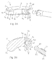
- the hollow space 5 may, for example, be manufactured by furnishing a cylindrical core bore hole 5a first in the solid material within the implant 1, and then skimming the sphere 5b in a second step, thereby expanding the core bore hole 5a at an appropriate position adjacent the elongate opening 8 along the core bore hole 5a to the shape of the sphere 5b, as can be seen in Fig. 2B .
- other manufacturing techniques of the implant such as rapid prototyping, mechanical or laser cutting, etc. are possible as well.
- Figs. 4A through 4E depict details of the engagement structures 70, 80 of the guiding sleeve 54. More specifically, the sleeve 54 is provided with a first engagement structure 80 and also with a second engagement structure 70 positioned adjacent each other at the distal end of the sleeve 54.
- the second engagement structure 70 engages with the guiding surfaces 16, 17 in a first state of insertion illustrated in Figs. 5A and 5B and in a second state, wherein a form-fit connection has been established as illustrated in Figs. 6A and 6B
- the first engagement structure 80 engages with the guiding surfaces 16, 17 in a third state illustrated in Figs. 7A and 7B , wherein the form-fit connection is secured or locked.
- the second engagement structure 70 comprises a front wall 71 configured to be brought into contact with the recessed portion 4d of the side wall 4.
- the front wall 71 for this purpose has a complementary shape with respect to the recessed portion 4d, i.e., cylindrical in this embodiment.
- the secondengagement structure 70 further has two opposite outer rounded guiding faces 72, 72' each shaped as a segment of a cylinder. Outer rounded guiding faces 72, 72' extend about a quarter circle around the longitudinal axis L of the sleeve 54 and define a diameter which is substantially equal to the distance between the guiding surfaces 16, 17 of the implant 1. Accordingly, the secondengagement structure 70 and the outer rounded guiding faces 72, 72' may be inserted into the channel defined between the guiding surfaces 16, 17 of implant 1.
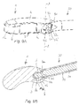
- Figs. 5A and 5B depict a first state after performing a step of inserting (see arrow 201 in Fig. 5A ) the engagement portion 53 of the drive shaft 51 through the elongate opening 8 into the hollow space 5 with the flat surfaces 61 of the engagement portion 53 being held in a horizontal posture (see Fig. 2A ).
- the engagement portion 53 and the neck portion 62 at the distal end of the drive shaft 51 project from the open distal end of the bore 65 of the sleeve 54 by a predetermined distance, such that when the engagement portion 53 abuts at the back surface of hollow space 5 in order to be fully received therein after insertion, the outer rounded guiding faces 72, 72' engage with the guiding surfaces 16, 17 of implant 1.
- the stop faces 73, 73' only abut on the guiding surfaces 16, 17, respectively.
- Figs. 6A and 6B depict a second state after performing a step of rotating (see arrow 202 in Fig. 6A ) the guiding sleeve 54 along with the drive shaft 51 held therein by an angle a of 90° in the clockwise direction about the longitudinal axis L.
- the engagement portion 53 has now been brought into a form-fit connection with the hollow space 5 in view of the respective complementary shapes.
- the flat surfaces 61 of the engagement portion 53 are perpendicular to the elongate opening 8 and thus, the engagement portion 53 cannot be removed from the hollow space 5 in the rotated posture.
- the knob 59 shown in Fig. 1 may be configured to interact with, for example, a protrusion or groove at the drive shaft 51 to provide a tactile response to the operator indicating that the drive shaft 51 has been retracted by a correct amount of distance such that the front wall may slide on the recessed portion 4d of the side wall 4 with less friction. Further retraction may serve to releasably fix a desired angular positon between the device 50 and the implant 1, if necessary.
- Fig. 10 shows in a perspective view an overview of an intervertebral implant 101 held by such a device 150 for inserting the implant into a space between two vertebrae of the vertebral column.
- the device 150 comprises a drive shaft 151 (see Figs. 11A, 11B ), a guiding sleeve 154, a handle 158, a turning handle 159 and an adjusting means 160, which may be an adjusting nut similar to the adjusting means 160 of the first embodiment, and which similarly interacts with the drive shaft 151 via threads.
- the drive shaft 151 is movably guided within the sleeve 154 and can be advanced or retracted with respect to the sleeve by actuating the adjusting means 160.
- Other means to facilitate advancement or retraction of the drive shaft 151 with respect to the guiding sleeve 154 may be contemplated as well, and the invention is not limited to the specific embodiment.
- the turning handle 159 permits to rotate the drive shaft 151 with respect to the guiding sleeve 154.
- Figs. 12A through 12E reveal details of the distal end of drive shaft 151.
- the drive shaft 151 comprises an engagement portion 153 having a spherical segment-shaped surface 157, wherein flat or planar surfaces 161, 161' are provided on opposite sides thereof as in the first embodiment.
- Position marks 269 are provided on one or both of the flat surfaces 161, 161' in the form of a strip. The strip indicates the operator of an orientation of the engagement portion 153 within the hollow space as will be explained below.
- the engagement portion 153 is also connected to a main portion 163 of the drive shaft 151 via a neck portion 162, which has a diameter smaller than a diameter of the main portion 163 as well as of the engagement portion 153, when seen the spherical segment-shaped surface 157 is considered, similar to the first embodiment.
- the diameter of the neck portion 162 substantially the same as the width of the engagement portion 153 in a direction perpendicular to the opposite flat surfaces 161, 161', as can directly be seen in Fig. 12B .
- the main portion 163 has a cylindrical shape which in this embodiment allows the drive portion 151 to be rotated with respect to the guiding sleeve 154.
- the intervertebral implant 101 of the second embodiment is also substantially of a kidney shape including a leading end 12 and a trailing end 13, a top surface 102, a bottom surface 103, and a side wall 104 extending between the top and bottom surfaces 102, 103.
- the top and bottom surfaces 102, 103 are substantially planar and parallel to each other except inclined portion 102a, which extends towards the leading end 12.
- the side wall 104 has a rounded portion 104a at the leading end 12, a concave portion 104b on a lateral side, a recessed portion 104d formed by inwardly extending wall portions at the trailing end 13 which will be explained in more detail below, and a convex portion 104e on the opposite lateral side.
- the top surface 102 as well as the bottom surface 103 each form an edge with each of the portions 104a, 104b and 104e of the side wall 104 at the leading end 12 and the lateral sides of the implant 101.
- the top surface 102 extends beyond the inwardly extending wall portions which form the recessed portion 104d of the side wall 4.
- overhanging extensions 106, 107 are formed as shown in Fig. 11A .
- An outer contour of the implant 101 may be defined by the edges of the top and bottom surfaces in this example including the edges of the extensions 106 and 107.
- Substantially planar surfaces 116, 117 are provided by these extensions 106 and 107, respectively, due to the presence of the recessed portion 104d of the side wall 104.
- the surfaces 116, 117 extend around the trailing end 13 in an arc-shaped manner and face towards each other with the recessed portions 104d extending therebetween.
- a recess is formed in the outer contour at the trailing end 13 of the implant 101, which is limited by recessed portions 104d of the side wall 104 and the surfaces 116, 117 of the extensions 106, 107.
- the surfaces 116, 117 may be denoted as guiding surfaces.
- the guiding surfaces 116, 117 of the second embodiment are parallel to each other, but may also be inclined or rounded.
- a hollow space 105 is provided within the implant 101 as can best be seen in Figs. 11A and 11B and has a shape of a sphere.
- the hollow space 105 of the second embodiment is formed by each one spherical segment 105b provided within extensions 106, 107 and facing each other, and by a spherical wall portion 105d which is in this example continuous with the inwardly extending wall portions of the recessed portion 4d.
- the hollow space 105 is open towards the outside.
- the inwardly extending wall portions of the recessed portion 104d form an elongate opening 108, which thus extends through the recessed portion 104d and provides access to the hollow space 105.
- the elongate opening 108 has a horizontal length larger than its vertical height and extends across the recessed portion 4d between respective wall portions provided as right side stops and left side stops along a direction substantially parallel to the plane of the top and bottom surfaces 102 and 103.
- the hollow space 105 has a diameter which is larger than the vertical height of the elongate opening 108, i.e., a larger than distance between the guiding surfaces 116, 117.
- the diameter is sufficiently large such that a circular hole 105c is created in each of the top surface 102 and the bottom surface 103.
- the circular holes 105c allow an operator to inspect an orientation of the engagement portions 153 of the drive shaft 151 when being received in the hollow space 105.
- the diameter of the hollow space 105 is the same or slightly larger than a diameter of the engagement portion 153 to permit receiving, rotating and supporting the engagement portion 153 therein.
- a distance between the guiding surfaces 116, 117 is the same as or slightly larger than a distance between the flat or planar surfaces 161, 161' of the engagement portion 153 to allow insertion of the engagement portion 153 into the elongate opening 108 in a horizontal posture.
- the hollow space 105 may be manufactured as in the first embodiment, for example by furnishing a cylindrical core bore hole 105a first, etc.
- the hollow space 105 has a symmetrical centre point M defined by the spherical segment-shaped surfaces 105b, 105d.
- the guiding surfaces 116, 117 are concentric about an axis A extending through the centre point M, which extends vertically (perpendicular to the plane of surfaces 102, 103) through the implant.
- Axis A represents a rotation axis of the implant 101 with respect to the device 150.
- the guiding surfaces 116, 117 are engaged by an engagement structure 180 provided at a distal end face of the guiding sleeve 154 when a connection is established between the device 150 and the implant 101 as shown in Fig. 10 .
- the neck portion 162 having the a diameter which is the same as the distance between the flat or planar surfaces 161, 161' of the engagement portion 153 is thus also sandwiched and slideably guided between guiding surfaces 116, 117 which further increases the stability and robustness of the system during engagement.
- the sleeve 154 is provided with a first engagement structure 180 in form of two projections 180a having a cylindrical-segment-shape and extending in a distal direction from the distal end face.
- the distal end face of a substantially annular shape and comprises a concave portion 171 a and a planar portion 171 b.
- the two projections 180a each extend from the planar portion 171 b and are located diametrically opposite to each other.
- An inner wall of each of the projections 180a is continuous with a surface of an inner bore 165 of the sleeve 154.
- the two projections also extend in a circumferential direction around the inner bore 165 between respective end faces thereof.
- These end faces in this embodiment have a planar shape and are parallel to each other.
- These end faces form guiding faces 181 configured for sliding engagement with the guiding surfaces 116, 117 of the implant.
- the distance between each two guiding faces of one projection 180a is the same or slightly less than a distance between the guiding surfaces 116, 117 of the implant 101.
- the concave portion 171 a is positioned between the projections 180a in a circumferential direction and has a curvature which corresponds to that of the arc-shaped outer contour of extensions 106, 107 to allow sliding and/or tight locking upon actuation of the adjusting means 160. It is noted that according to further modifications, the portions 171 a may also be planar. Further, the guiding faces 181 may also have rounded shape and may be inclined with respect to each other and with respect to the guiding surfaces of the implant when the device is attached.
- the sleeve 154 may have a flattened portion 257 extending from the concave portion 171 a of the distal end face along an outer surface of the sleeve and a portion 258 extending from the planar portion 171 b in a similar manner.
- the flattened portions facilitate gripping (portion 157) or receiving a position mark 259 provided as a strip.
- the first engagement structure 180 engages with the guiding surfaces 116, 117 in all states of the attachment process, i.e., in a first state 301 of insertion of the engagement portion 153 into the hollow space 105 illustrated in Figs. 14A and 14B , in a second state wherein a form-fit connection has been established as illustrated in Figs.
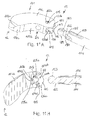
- Figs. 14A and 14B depict a first state after performing a step of inserting (see arrow 301 in Fig. 14A ) the engagement portion 153 of the drive shaft 151 through the elongate opening 108 into the hollow space 105.
- the flat surfaces 161 of the engagement portion 153 are held in a horizontal posture ( Figs. 11A or 12A ).
- the engagement portion 153 and the neck portion 162 at the distal end of the drive shaft 151 project from the open distal end of the inner bore 165 of the sleeve 154 by a predetermined distance, such that when the engagement portion 153 abuts at the back surface of hollow space 105, the projections 180a of engagement structure 180 enter the channel or elongate opening 108 defined the recessed portion 4d.
- the guiding faces 181 at the projections 180a engage with the guiding surfaces 116, 117 of implant 101.
- the arrangement of two guiding faces on either side of the sleeve prevents any rotation of the sleeve around its longitudinal direction L.
- the concave portions 171 a of the distal end surface of the guiding sleeve 154 abut on the arc-shaped outer contour of the implant 101 in a region of the extensions 106, 107, which includes the corresponding curvature.
- the position mark 269 of the drive shaft 151 is still aligned (see Fig. 11A ) with the position mark 259 at the sleeve, and is visible through the circular hole 105c.
- Figs. 15A and 15B depict a second state after performing a step of rotating the drive shaft 151 (see arrow 302 in Fig. 6A , the drive shaft is indicated with dotted lines) by an angle ⁇ of 90° in the clockwise direction about the longitudinal axis L with respect to the guiding sleeve 154.
- This rotation may be effected by actuating the turning handle 159 provided at handle 158 as shown in Fig. 10 .
- the engagement portion 153 is thereby transferred into a form-fit connection with the hollow space 105.
- the engagement portion 153 cannot be removed from the hollow space 105 in the rotated posture. Meanwhile, the position mark 269 disappeared from circular hole 105c due to the rotation of the drive shaft 151.
- Figs. 16A and 16B depict a third state after performing a step of drawing back the drive shaft 151 (see arrow 303) with respect to the guiding sleeve 154 using, for example, the adjustment nut 160 shown in Fig. 10 .
- the sleeve 154 is urged in the distal direction and pressed via concave portion 171 a against the outer contour of the extensions 106, 107, while the drive shaft 151 is drawn back into the proximal direction with the implant 101 held in the form-fit connection.
- the mutual displacement between the drive shaft 151 and the guiding sleeve 154 is small, and no further engagement portion is introduced into the channel of the implant between guiding surfaces.
- the instant step of drawing back the drive shaft 151 with respect to the sleeve thus only serves to fix or lock an angular position of the implant 101 with respect to the device 151, or to adjust the amount of friction between the guiding faces and surfaces.
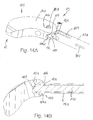
- Figs. 17A and 17B depict a state of the implant 101 in which the angular positon is changed from that shown in Figs. 16A and 16B by sliding the engagement structure 180 of the guiding sleeve along the outer contour of the extensions 106, 107 and the guiding surfaces 116, 117, leftward (indicated by the arrow) until one of the projections 180a of the sleeve 154 abuts on a left-side inwardly extending wall portion of the recessed portion 4d, or elongate opening 8, respectively.
- the rotation of the implant 101 is around axis A extending through the centre point M of the hollow space 105.
- the concave portion 171 a of the distal end face of the sleeve abuts against and slides with respect to the arc-shaped or curved portion 106a of the outer contour of extensions 106, 107.
- the curvatures correspond to each other such that a smoothly guided sliding contact at a constant radial distance from centre point M of the hollow space 105 is achieved.
- FIGs. 18A and 18B depict a state of the implant 101 in which the angular positon is changed from that shown in Figs. 16A and 16B by sliding the engagement structure 180 of the guiding sleeve 154 along the outer contour of the extensions 106, 107 and the guiding surfaces 116, 117 rightward (see arrows in Figs. 18A, 18B ) until the other one of the projections 180a of the sleeve 154 abuts on a right-side inwardly extending wall portion of the recessed portion 4d, or elongate opening 8, respectively.
- the rotation of the implant 101 is around axis A.
- the planar portion 171 b of the distal end face of the guiding sleeve 154 abuts against and slides with respect to the correspondingly shaped straight portion 106b of the outer contour of extensions 106, 107 which is recessed from curved portion 106a with regard to a radial distance from the centre point M. If a slight pressure force exerted on the sleeve in a distal direction is maintained throughout rotation of the implant 101 around axis A, the sleeve thus latches-in, when reaching the position shown in Figs. 18A and 18B . The latched-in state provides for a particular robust connection between the implant and the device during transfer to the implant site.
- the implant shown in the above described embodiment is only an example.
- the contour and shape of the implant may be different according to the specific clinical requirements.
- the contour may have any other shape, such as circular, rectangular, oval, etc.
- the height of the side wall may be constant throughout the implant.
- the elongate opening can be at another position. Still further, the elongate opening may extend vertically or in an inclined posture. Also, only one opening or more than one opening may be provided. Also, it may be possible to adapt existing intervertebral implants without an opening, by providing it with such an opening as proposed herein.
- the recessed portions 4c and/or 4d of the side wall 4, and/or the front wall 71 of the sleeve 54, according to the first embodiment may be provided with ratcheting features, or teeth or ribs and grooves, or roughened surfaces to increase a clamping force, when brought into contact with each other.
- the surface may be coated to increase friction.
- the drive shaft 51, 151 may be rotated by an angle ⁇ of about 90°.
- ⁇ of about 90°.
- other ranges of rotation are possible as well.
- releasable snap-in means may be provided to provide a tactile response to the operator, that a desired state has been reached with respect to the engagement portion 53.
- stops defining end points may be provided with regard to the rotation of the drive shaft within the sleeve.
- the implant is made of a biocompatible material.
- the implant can be made of stainless steel or titanium, or of a biocompatible metal alloy, such as a nickel titanium alloy, for example Nitinol, or can be made of a biocompatible plastic material, for example, PEEK (polyetheretherketone).
- an intervertebral implant having the hollow space formed within the implant and accessible through the elongate opening extending through the recessed portion of the side wall, wherein the hollow space is shaped to receive the engagement portion of the drive shaft of the device for insertion of an implant; wherein the hollow space is shaped to receive the engagement portion of the drive shaft of the insertion tool in a first state of insertion, and to support the engagement portion in a second state in a form-fit connection, in which the engagement portion is rotated from the first state by an angle ⁇ .
- the hollow space may have a spherical shape.
- an intervertebral implant having the hollow space formed within the implant and accessible through the elongate opening extending through the recessed portion of the side wall, wherein the hollow space is shaped to receive the engagement portion of the drive shaft of the device for insertion of an implant; wherein the hollow space has a spherical shape.
Landscapes
- Health & Medical Sciences (AREA)
- Engineering & Computer Science (AREA)
- Biomedical Technology (AREA)
- Orthopedic Medicine & Surgery (AREA)
- Neurology (AREA)
- Transplantation (AREA)
- Heart & Thoracic Surgery (AREA)
- Oral & Maxillofacial Surgery (AREA)
- Cardiology (AREA)
- Vascular Medicine (AREA)
- Life Sciences & Earth Sciences (AREA)
- Animal Behavior & Ethology (AREA)
- General Health & Medical Sciences (AREA)
- Public Health (AREA)
- Veterinary Medicine (AREA)
- Physical Education & Sports Medicine (AREA)
- Prostheses (AREA)
- Surgical Instruments (AREA)
Abstract
the intervertebral implant having a hollow space (5, 105) formed within the intervertebral implant (1, 101) and accessible through an elongate opening (8, 108) extending through a recessed portion (4d, 104d) of the side wall (4, 104),
wherein the hollow space (5, 105) has a spherical segment shape to receive an engagement portion (53, 153) of a drive shaft (51, 151) of a device (50, 150) for insertion of an implant, and
wherein the recessed portion (4d, 104d) of the side wall (4, 104) defines at least two guiding surfaces (16, 17; 116, 117) extending around an end (13, 113) of the intervertebral implant in an arc-shaped manner and facing one another, the at least two guiding surfaces (16, 17; 116, 117) being configured for sliding engagement by a portion of a sleeve (54, 154) of a device (50, 150) for insertion of an implant.
Description
- The present invention relates to an intervertebral implant having a top surface configured to engage a first vertebral body, a bottom surface configured to engage a second vertebral body and a side wall connecting the top surface and the bottom surface, and a hollow space formed within the implant and accessible through an elongate opening extending through a portion of the side wall.
- The invention further relates to a device for inserting the intervertebral implant into a body, comprising a drive shaft including an engagement portion for engaging a hollow space of an intervertebral implant in a form-fit connection, and a sleeve movably guiding the drive shaft and having a longitudinal axis.
- An intervertebral implant which is configured to be engaged by an insertion device for insertion of the implant between first and second vertebral members is known from
DE 10 2008 045 174 A1 . The intervertebral implant has an insertion opening including a slit-like elongated shape that extends through the side wall. The insertion opening provides access to an inner space of the implant for the insertion device. The insertion device has a sleeve and a shaft guided through the sleeve, wherein an elongate support projection having a cylindrical support surface is provided at a distal end of the shaft. - The shaft can be rotated with respect to the sleeve, such that the elongate support projection is first inserted through the slit-like opening into the inner space and then rotated to establish a connection. The shaft may then be drawn back with respect to the sleeve in order to connect the cylindrical support surface of the shaft with a corresponding cylindrical recess formed at an inner wall of the inner space in a direction transverse to the insertion opening in a form-fit manner. This connection allows for rotating and selectively positioning the implant with respect to the insertion tool, wherein its shaft follows the path of the slit-like opening. A counterforce and sliding engagement is achieved by an appropriately shaped front wall of the distal end and of the sleeve, which engages the side wall of the implant around the insertion opening.
- Another insertion device, which has a shaft-like section that may be rotated after insertion to establish a connection between the device and an intervertebral implant, is disclosed in
US 2007/0162129 A1 . At the distal end of the shaft, an elongated head having a cuboid shape is provided. Drawing back the distal end then sandwiches an outer wall of the implant between a back side surface of the cuboid-shaped elongate head and a stop provided at distal end of a sleeve-like first section of the device. -
US 8,673,012 B2 also discloses an intervertebral spacer which inFigs. 8A-C thereof has an inner cavity and a through hole, through which a portion of an insertion tool having transverse extensions may be inserted and then rotated, to establish a connection between a trailing end of the intervertebral spacer and the insertion tool. Thereby, an appropriately shaped front wall of the insertion tool having engagement features is pressed onto a side wall of the intervertebral spacer. -
Documents EP 2 535 021 A1 andEP 2 535 022 A1 - It is an object of the invention to provide an intervertebral implant, and a system comprising an intervertebral implant and a device for inserting the same that is simplified in terms of its use and in view of the possibilities of final positioning.
- The object is solved by an intervertebral implant according to
claim 1, and by a system comprising the intervertebral implant and a device for inserting the same according to claim 10. Further aspects and advantageous embodiments are provided in the appended claims. - According to one or more embodiments of the invention, an intervertebral implant is provided wherein a sidewall connecting respective top and bottom surfaces includes a portion which is recessed or may according to one specific embodiment include a wall portion set back from an outer contour of the implant. This recessed portion includes an elongate opening suited for insertion of an engagement portion of a drive shaft of an insertion tool into a hollow space provided within the implant. The outer contour of the implant defines at least two guiding surfaces facing one another and configured for sliding engagement by a portion of a sleeve of the insertion tool.
- Thus, a connection between the implant of these embodiments and a device for insertion of the intervertebral implant into a body is improved in that there is not or not only established a force acting onto the (recessed) side wall but (also) on one or more engagement surfaces facing a recess. Hence, the guiding stability of the implant being engaged by a respective insertion device is enhanced and failure of the connection is avoided.
- In one or more embodiments, the engagement surfaces are provided at extensions of the top and/or bottom surfaces, respectively, which extend beyond an intersection of the recessed portion of the side wall and the top and bottom surfaces, respectively. The outer edges of the extensions form the outer contour of the implant at this location, from which the recessed portion is then set back to form a channel extending between the extensions.
- Embodiments of the implant may include a hollow space which is shaped to receive an engagement portion of a drive shaft of an insertion tool in a first state of insertion. The hollow space allows to establish a form-fit connection with a complementarily shaped engagement portion of the insertion device. In view of the form-fit connection no sandwiching or compression of a thin side wall between the engagement portion of the drive shaft and a front wall or stop at the distal end of the sleeve is necessary. This allows to define small dimensions of the hollow space within the implant, for example only in a trailing end of the implant.
- As a full form-fit connection is established between the hollow space and the engagement portion, further connection structures such as above described engagement surfaces may be specifically adapted to other applications than simple fixation of the implant. For example, guiding surfaces may help in guiding and sliding engagement structures of the sleeve of an insertion tool. Alternatively or additionally, engagement structures of the insertion device may be adapted to prevent removal of the engagement portion from the form-fit connection. Still further, engagement structures of the insertion device may be adapted to the guiding surfaces such as to improve handling of the implant by defining a single-sided rotation, as will be described below.
- According to embodiments, the hollow space is spherical. When the engagement portion of the insertion tool is also at least partially spherical as well, a connection in the form of a ball joint is established.
- Further, according to embodiments of the invention, a device for inserting an intervertebral implant into a body comprises a drive shaft, which includes an engagement portion for engaging the hollow space of an intervertebral implant, and a sleeve movably holding and guiding the drive shaft and having a longitudinal axis. The sleeve comprises at or adjacent a first end thereof a first engagement structure.
- As in the embodiments above regarding the implant, the engagement portion of the insertion device may, for example, have a shape corresponding to that of a hollow space to provide a form-fit connection, such as a spherical segment shape. Further, the shape of the engagement portion may be flattened such as to allow passing the same through an elongate opening of the implant prior to establishing the form-fit connection.
- For example, if the engagement portion has the partially spherical shape, segments may be removed from a sphere on opposite sides thereof in order to obtain two flat parallel planes on opposite sides of the sphere, which extend also parallel to the longitudinal axis of the sleeve of the insertion device, which axis defines the direction of insertion. Both the hollow space and the engagement portion have a simple structure, require few space, are easy to manufacture, and provide a stable, large contact area form-fit connection.
- The first engagement structure of the sleeve may engage the guiding surfaces of the recessed portion, when the engagement portion is supported in the hollow space and the sleeve is moved toward the recessed portion. Thereby, the first engagement structure is shaped to allow a sliding rotation of the sleeve along the guiding surfaces and around an axis extending through the hollow space, but to prevent rotation of the sleeve about its own longitudinal axis.
- In one specific first embodiment there are provided two engagement structures positioned adjacent each other, namely the first and a second engagement structure. The second engagement structure may first engage the guiding surfaces of the intervertebral implant, when the engagement portion is received in the hollow space in a first state of insertion. Thereby, the second engagement structure is shaped to allow a common rotation of the sleeve and the drive shaft about the longitudinal axis to transfer the engagement portion into a second state. In the second state the engagement portion of the shaft it is supported in a form fit connection in the hollow space. The shaft in this embodiment cannot rotate with respect to the sleeve. Then, an adjustment of the sleeve with respect to the drive shaft and implant allows to bring the engagement structures in contact with the guiding surfaces of the implant in a sequential manner. Both engagement structures differ from each other in that the second engagement structure allows rotation of the sleeve while the first engagement structure prevents rotation of the sleeve. In other words, the second engagement structure allows establishing the form-fit connection by rotation, and the first engagement structure locks or secures the form-fit connection (the third or locked state).
- In another specific second embodiment there is provided only one first engagement structure at the sleeve thus facilitating a simple structure. Herein, rotation of the drive shaft with respect to the sleeve is permitted. As noted, the first engagement structure may engage the guiding surfaces of the intervertebral implant, when the engagement portion is received in the hollow space in a first state of insertion. In this first state, the first engagement structure already prevents rotation of the sleeve with respect to the implant. Next, the shaft is allowed to be rotated with respect to the sleeve by an angle α about the longitudinal axis to transfer the engagement portion of the shaft into a second state. In the second state the engagement portion it is supported in a form fit connection in the hollow space.
- In a more refined embodiment, an outer contour of the implant in the region of the guiding surfaces defines a rounded portion and a portion recessed form the rounded shape, in particular a straight portion. The recessed or straight portion allows a latched-in state of the implant with respect to the device, which may correspond, for example, to a specific posture of the implant maintained during insertion of the implant towards the implant site. The latched-in state provides for a robust connection between the implant and the device and the assists in maintaining the posture until the implant reaches the implant site and also provides a tactile response to the surgeon to indicate that the implant is now urged to rotate at the first end of the device.
- According to one or more embodiments, the implant and the device are particularly configured for a transforaminal lumbar interbody fusion surgery (TLIF), the implant having a kidney-shape, a leading end and a trailing end, the hollow space, the elongate opening, and the recessed portion of the side wall as well as the engagement surfaces being provided at the trailing end.
- The invention will be best understood by the following detailed description of some embodiments taken in conjunction with the accompanying drawings. Therein,
-
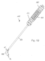
Fig. 1 shows in a perspective view an overview of an intervertebral implant held by a device for inserting the implant into a body according to a first embodiments of the invention; -
Fig. 2A shows an enlarged perspective view of the intervertebral implant and a distal end portion of the device as shown inFig. 1 in a state prior to insertion; -
Fig. 2B shows the same asFig. 2A , but in a cross-sectional top view; -
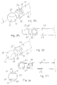
Fig. 3A shows in a perspective view a distal end portion of a drive shaft of the device shown inFig. 2A in a first state of insertion (implant not shown); -
Fig. 3B shows the same asFig. 3A , but in a side view; -
Fig. 3C shows the same asFig. 3A , but rotated by 90° into a second form-fit state (implant not shown); -
Fig. 3D shows the same asFig. 3C , but in a side view; -
Fig. 3E shows the same asFig. 3A , but in a front view from the distal side; -
Fig. 4A shows in a top perspective view a distal end portion of a guiding sleeve of the device shown inFig. 2A ; -
Fig. 4B shows the same asFig. 4A , but in a side view; -
Fig. 4C shows the same asFig. 4A , but in a bottom perspective view; -
Fig. 4D shows the same asFig. 4C , but in a side view; -
Fig. 4E shows the same asFig. 4A , but in a front view from the distal side; -
Fig. 5A shows the same asFig. 2A , but in a first state of insertion of the drive shaft and engagement portion into the intervertebral implant; -
Fig. 5B shows the same asFig. 5A , but in a cross-sectional top view; -
Fig. 6A shows the same asFig. 5A , but after rotation of the drive shaft and engagement portion into a second state of a form-fit connection between the implant and the device; -
Fig. 6B shows the same asFig. 6A , but in a cross-sectional top view; -
Fig. 7A shows the same asFig. 6A , but after drawing back the drive shaft to lock the form-fit connection between the implant and the device in a third state; -
Fig. 7B shows the same asFig. 7A , but in a cross-sectional top view; -
Fig. 8A shows in a perspective view the use of the intervertebral implant and the distal end portion of the device firmly connected as shown inFig. 7A in a state wherein the implant is rotated up to a left side abutment between the drive shaft and the elongate opening; -
Fig. 8B shows the same asFig. 8A , but in a cross-sectional top view; -
Fig. 9A shows in a perspective view the use of the intervertebral implant and the distal end portion of the device firmly connected as shown inFig. 7A in a state wherein the implant is rotated up to a right side abutment between the drive shaft and the elongate opening; -
Fig. 9B shows the same asFig. 9A , but in a cross-sectional top view. -
Fig. 10 shows in a perspective view an overview of an intervertebral implant held by a device for inserting the implant into a body according to second embodiments of the invention; -
Fig. 11A shows an enlarged perspective view of the intervertebral implant and a distal end portion of the device as shown inFig. 10 in a state prior to insertion; -
Fig. 11B shows the same asFig. 11A , but in a cross-sectional top view; -
Fig. 12A shows in a perspective view a distal end portion of a drive shaft of the device shown inFig, 11A in a first state of insertion (implant not shown); -
Fig. 12B shows the same asFig. 12A , but in a side view; -
Fig. 12C shows the same asFig. 12A , but rotated by 90° into a second form-fit state (implant not shown); -
Fig. 12D shows the same asFig. 12C , but in a side view; -
Fig. 12E shows the same asFig. 12A , but in a front view from the distal side; -
Fig. 13A shows in a top perspective view a distal end portion of a guiding sleeve of the device shown inFig. 11A ; -
Fig. 13B shows the same asFig. 13A , but in a side view; -
Fig. 13C shows the same asFig. 13A , but in a bottom perspective view; -
Fig. 13D shows the same asFig. 13C , but in a side view; -
Fig. 13E shows the same asFig. 13A , but in a front view from the distal side; -
Fig. 14A shows the same asFig. 11A , but in a first state of insertion of the drive shaft and engagement portion into the intervertebral implant; -
Fig. 14B shows the same asFig. 14A , but in a cross-sectional top view; -
Fig. 15A shows the same asFig. 14A , but after rotation of the drive shaft and engagement portion into a second state of a form-fit connection between the implant and the device; -
Fig. 15B shows the same asFig. 15A , but in a cross-sectional top view; -
Fig. 16A shows the same asFig. 15A , but after drawing back the drive shaft to lock the form-fit connection between the implant and the device in a third state; -
Fig. 16B shows the same asFig. 16A , but in a cross-sectional top view; -
Fig. 17A shows in a top view the use of the intervertebral implant and the distal end portion of the device firmly connected as shown inFig. 16A in a state wherein the implant is rotated up to a left side abutment between the drive shaft and the elongate opening; -
Fig. 17B shows the same asFig. 17A , but in a cross-sectional top view; -
Fig. 18A shows in a top view the use of the intervertebral implant and the distal end portion of the device firmly connected as shown inFig. 16A in a state wherein the implant is rotated up to a right side abutment between the drive shaft and the elongate opening; -
Fig. 18B shows the same asFig. 18A , but in a cross-sectional top view. - First embodiments both of an intervertebral implant as well as of a device for inserting an intervertebral implant into a body are further detailed with reference to
Figs. 1-9B .Fig. 1 shows in a perspective view an overview of anintervertebral implant 1 held by adevice 50 for inserting the implant into a body, or, more specifically, into a space between two vertebrae of the vertebral column. - The
device 50 includes a drive shaft 51 (seeFigs. 2A, 2B ), a guidingsleeve 54, ahandle 58, aresilient knob 59, and an adjusting means 60, which in an embodiment is an adjusting nut, which has an internal thread (not shown) that interacts with an external thread (not shown) at or near the proximal end of thedrive shaft 51. Thedrive shaft 51 is movably guided within thesleeve 54 and can be advanced or retracted with respect to the sleeve by rotating the adjusting nut of the adjusting means 60. Other means to facilitate advancement or retraction of thedrive shaft 51 with respect to the guidingsleeve 54 may be contemplated as well, and the invention is not limited to the specific embodiment. - As can be seen particularly from
Figs. 3A through 3E , which show details of the distal end ofdrive shaft 51, thedrive shaft 51 comprises anengagement portion 53 having a partially spherical shape (spherical surface 57), wherein on opposite sides thereof, segments of the sphere are removed to yieldflat surfaces 61, 61'. The flat surfaces 61, 61' provide for a flattened shape of theengagement portion 53 which allows introduction of the same through a narrowelongate opening 8 of theimplant 1. - The
engagement portion 53 is connected to amain portion 63 of thedrive shaft 51 via aneck portion 62, which has a diameter smaller than a diameter of themain portion 63. However, the diameter of theneck portion 62, which in an embodiment is cylindrical, is substantially the same as the width of theengagement portion 53 in a direction perpendicular to the oppositeflat surfaces 61, 61', as can be seen inFig. 3B . - The
drive shaft 51 further has adjacent theneck portion 62 and at an end of themain portion 63 twoopposite protrusions 56, 56' extending perpendicular to a longitudinal axis of thedrive shaft 51. One of the protrusions (protrusion 56') is provided with alongitudinal groove 52 extending along a portion of thedrive shaft 51. Theprotrusions 56, 56' and thegroove 52 interact with complementary features, such asrecesses 64, 64' and arib 55 provided in aninner bore 65 of the guiding sleeve 54 (seeFigs. 4A through 4E ). As a result, thedrive shaft 51 can be displaced with respect to the guidingsleeve 54 along a longitudinal axis L of the guidingsleeve 54 using the adjusting means 60 as noted above, but cannot be rotated with respect to the guidingsleeve 54. - As can be seen from
Figs. 1 ,2A and 2B , theintervertebral implant 1 is substantially of a kidney shape and has aleading end 12 and a trailingend 13. The terms "leading" and "trailing" originate from the manner of placement into the space between the vertebrae from a lateral side in this specific embodiment (which refers to a TLIF cage). Theimplant 1 has atop surface 2, abottom surface 3, and aside wall 4 extending between the top andbottom surfaces bottom surfaces inclined portions 2a, 2b, and 3b extending towards the leadingend 12, which facilitates easier insertion between the vertebrae. - The
side wall 4 comprises, in the example of the kidney-shaped TLIF cage, a cylindrical portion 4a at theleading end 12, a concave portion 4b on a lateral side, a substantially cylindrical recessedportion 4d at the trailingend 13, recessedtransition portions 4c on both sides of the recessedportion 4d, and a convex portion 4e on the opposite lateral side. - The
top surface 2 includes an edge with each of the portions 4a, 4b and 4e of theside wall 4 at theleading end 12 and the lateral sides of theimplant 1. However, at the trailingend 13, thetop surface 2 extends beyond theportions side wall 4, which thus forms an overhanging extension 7 as can be seen inFig. 2A . Similarly, thebottom surface 3 includes an edge with each of the portions 4a, 4b and 4e of theside wall 4 at theleading end 12 and the lateral sides of theimplant 1. At the trailingend 13, thebottom surface 3 extends beyond theportions side wall 4, which thus forms an overhanging extension 6 opposite the overhanging extension 7. As a result,portions side wall 4 are recessed or set back from an outer contour of theimplant 1, which is defined by the edges of the top andbottom surfaces - As shown in
Fig. 2A , the overhanging extensions 6 and 7 form surfaces 16, 17, respectively, due to the set back of theportions side wall 4. More specifically, surfaces 16, 17 extend around the trailingend 13 in an arc-shaped manner and face towards each other with the recessedportions side wall 4 extending therebetween. Thus, a channel or recess is formed in the outer contour at the trailingend 13 of theimplant 1 between extension 6, 7, which is limited byportions side wall 4 and thesurfaces surfaces sleeve 54, as will be explained below, thesurfaces surfaces - As shown in
Fig. 2A , anelongate opening 8 is formed within the cylindrically shaped recessedportion 4d of theside wall 4. The elongate opening has a horizontal length larger than its vertical height and extends across theportion 4d of theside wall 4 between a right side end or stop 8a and a left side end or stop 8b along a direction substantially parallel to the plane of the top andbottom surfaces - The
elongate opening 8 provides access to ahollow space 5 positioned adjacent theelongate opening 8 within theimplant 1. Thehollow space 5 has a shape of asphere 5b. Moreover, thehollow space 5 has a diameter which is larger than the vertical height of theelongate opening 8. Thehollow space 5 may, for example, be manufactured by furnishing a cylindrical core borehole 5a first in the solid material within theimplant 1, and then skimming thesphere 5b in a second step, thereby expanding the core borehole 5a at an appropriate position adjacent theelongate opening 8 along the core borehole 5a to the shape of thesphere 5b, as can be seen inFig. 2B . However, other manufacturing techniques of the implant such as rapid prototyping, mechanical or laser cutting, etc. are possible as well. - As can be seen particularly in the top view of
Fig. 2B , thehollow space 5 has a symmetrical center point M of thesphere 5b, and theportion 4d of theside wall 4 as well as the guiding surfaces 16, 17 (inFig. 2B , only thesurface 16 is shown) are concentric about an axis A extending through the center point M. The axis A extends vertically through the implant through the center point M, and represents a rotation axis of theimplant 1 with respect to thedevice 50. As will be described below, the recessedportion 4d and the guiding surfaces 16, 17 are engaged by theengagement structures sleeve 54 when a connection is established between thedevice 50 and theimplant 1 as shown inFig. 1 . The engagement may be a sliding engagement to allow for rotation and a range of angular positions of theimplant 1 with respect to thedevice 50. Moreover, the guiding surfaces 16, 17 help in firmly supporting theengagement structures - Returning to the description of the
device 50,Figs. 4A through 4E depict details of theengagement structures sleeve 54. More specifically, thesleeve 54 is provided with afirst engagement structure 80 and also with asecond engagement structure 70 positioned adjacent each other at the distal end of thesleeve 54. In operation of thedevice 50 andimplant 1, thesecond engagement structure 70 engages with the guiding surfaces 16, 17 in a first state of insertion illustrated inFigs. 5A and 5B and in a second state, wherein a form-fit connection has been established as illustrated inFigs. 6A and 6B , and thefirst engagement structure 80 engages with the guiding surfaces 16, 17 in a third state illustrated inFigs. 7A and 7B , wherein the form-fit connection is secured or locked. - The
second engagement structure 70 comprises afront wall 71 configured to be brought into contact with the recessedportion 4d of theside wall 4. Thefront wall 71 for this purpose has a complementary shape with respect to the recessedportion 4d, i.e., cylindrical in this embodiment. - The
secondengagement structure 70 further has two opposite outer rounded guiding faces 72, 72' each shaped as a segment of a cylinder. Outer rounded guiding faces 72, 72' extend about a quarter circle around the longitudinal axis L of thesleeve 54 and define a diameter which is substantially equal to the distance between the guidingsurfaces implant 1. Accordingly, thesecondengagement structure 70 and the outer rounded guiding faces 72, 72' may be inserted into the channel defined between the guidingsurfaces implant 1. - The
secondengagement structure 70 further has two opposite stops or stop faces 73, 73' which are continuous with the outer rounded guiding faces 72, 72' but deviate from a cylinder shape towards larger radii. The stop faces 73, 73' in this embodiment correspond to parts of a cuboid shape. When seen from the front side, the stop faces 73, 73' provide a square profile while the rounded guiding faces 72, 72' provide a circular profile. As a result, a diameter between portions of the opposite stop faces 73, 73' extending through the longitudinal axis L is larger than the distance between the opposite guiding surfaces 16, 17 of theimplant 1. -
Figs. 5A and 5B depict a first state after performing a step of inserting (seearrow 201 inFig. 5A ) theengagement portion 53 of thedrive shaft 51 through theelongate opening 8 into thehollow space 5 with theflat surfaces 61 of theengagement portion 53 being held in a horizontal posture (seeFig. 2A ). In this first state, theengagement portion 53 and theneck portion 62 at the distal end of thedrive shaft 51 project from the open distal end of thebore 65 of thesleeve 54 by a predetermined distance, such that when theengagement portion 53 abuts at the back surface ofhollow space 5 in order to be fully received therein after insertion, the outer rounded guiding faces 72, 72' engage with the guiding surfaces 16, 17 ofimplant 1. In this posture, the stop faces 73, 73' only abut on the guiding surfaces 16, 17, respectively. - As a result, the guiding
sleeve 54 can be rotated with respect to the guiding surfaces 16, 17 only in one direction, while the stop faces 73, 73', due to the abutment and larger diameter, impede rotation in the other direction. -
Figs. 6A and 6B depict a second state after performing a step of rotating (seearrow 202 inFig. 6A ) the guidingsleeve 54 along with thedrive shaft 51 held therein by an angle a of 90° in the clockwise direction about the longitudinal axis L. Theengagement portion 53 has now been brought into a form-fit connection with thehollow space 5 in view of the respective complementary shapes. The flat surfaces 61 of theengagement portion 53 are perpendicular to theelongate opening 8 and thus, theengagement portion 53 cannot be removed from thehollow space 5 in the rotated posture. - Also, while the rounded guiding faces 72, 72' allow sliding rotation of the
sleeve 54 with respect to the guiding surfaces 16, 17, having rotated thesleeve 54 by about a quarter circle (i.e., α = 90°), the stop faces 73, 73' again abut on the guiding surfaces 16, 17 to impede further rotation of thesleeve 54. This stop and end point of rotation provides the operator with a clear indication that a form-fit connection has been established. Also, in case that removal of thedevice 50 from theimplant 1 is intended, for example when theimplant 1 has been placed between two vertebrae, there is only one possibility of rotating back thesleeve 54 into the other direction (counterclockwise) by an angle α of 90°. This allows the operator to accurately control the handling of thedevice 50 andimplant 1 under conditions of limited visibility. -
Figs. 7A and 7B depict a third state after performing a step of retracting the drive shaft 51 (see arrow 203) with respect to the guidingsleeve 54 by a predetermined distance using, for example, theadjustment nut 60 shown inFig. 1 . In this embodiment, theneck portion 62 is almost retracted within thebore 65 of thesleeve 54. Since theengagement portion 53 is firmly held in view of the form-fit connection with thehollow space 5, thesleeve 54 is thus drawn and moved toward theimplant 1. More specifically, thefront wall 71 of thesecond engagement structure 70 is brought in contact with the recessedportion 4d of theside wall 4 of theimplant 1. Also, the rounded guiding faces 72, 72' and the abutment faces of thestops 73, 73' slide inwards at the guiding surfaces 16, 17. - As a result, flat faces 81 provided with respect to the
first engagement structure 80, which are continuous with the abutment faces of thestops 73, 73' are brought into engagement with the guiding surfaces 16, 17 of theimplant 1. However, since thefirst engagement structure 80 fails to have rounded guiding faces having a diameter equal to the distance between the guidingsurfaces sleeve 54 can no more be rotated in this third state about its longitudinal axis L. Consequently, the form-fit connection between theengagement portion 53 and thehollow space 5 is locked or secured. - The
knob 59 shown inFig. 1 may be configured to interact with, for example, a protrusion or groove at thedrive shaft 51 to provide a tactile response to the operator indicating that thedrive shaft 51 has been retracted by a correct amount of distance such that the front wall may slide on the recessedportion 4d of theside wall 4 with less friction. Further retraction may serve to releasably fix a desired angular positon between thedevice 50 and theimplant 1, if necessary. -
Figs. 8A and 8B depict a state of theimplant 1 in which the angular positon is changed from that shown inFigs. 7A and 7B by sliding theengagement structures portion 4d and the guiding surfaces 16, 17, respectively, leftward until a portion of theneck portion 62 still protruding from thesleeve 54 abuts on a left-side stop face 8b of theelongate opening 8. - Similarly,
Figs. 9A and 9B depict a state of theimplant 1 in which the angular positon is changed from that shown inFigs. 7A and 7B by sliding theengagement structures portion 4d and the guiding surfaces 16, 17, respectively, rightward until a portion of theneck portion 62 still protruding from thesleeve 54 abuts on a right-side stop face 8a of theelongate opening 8. - Using the steps as outlined above, a placement of the
implant 1 according to the first embodiment between two vertebrae may be performed using thedevice 50 for inserting the implant in a method as illustrated, for example, inFigs. 9a) through 9f) ofdocument EP 2 535 022 A1 , which is in this regard incorporated herein by reference, whereinimplant 1 and device 20 of that document are replaced with theimplant 1 and thedevice 50 of the present first embodiments, respectively. - Next, second embodiments both of an intervertebral implant as well as of a device, respectively, for inserting an intervertebral implant into a body are explained with reference to
Figs. 10-18B , The overall structure of the implant of this second embodiment is similar to that of the first embodiment and repeated discussion of similar features will be omitted in the following. One difference between the embodiments of the system can be seen in that only afirst engagement structure 180 is provided at the device in in the second embodiment, but a second engagement structure is omitted herein. In the first embodiment, thesecond engagement structure 70 allows for a joint rotation of the guiding sleeve and the drive shaft with respect to the implant in order to establish the form-fit connection. In the second embodiment, as will be described below, a rotation of the drive shaft with respect to the guiding sleeve is allowed such that a more simple sleeve design may be provided.Fig. 10 shows in a perspective view an overview of anintervertebral implant 101 held by such adevice 150 for inserting the implant into a space between two vertebrae of the vertebral column. - The
device 150 comprises a drive shaft 151 (seeFigs. 11A, 11B ), a guidingsleeve 154, ahandle 158, aturning handle 159 and an adjusting means 160, which may be an adjusting nut similar to the adjusting means 160 of the first embodiment, and which similarly interacts with thedrive shaft 151 via threads. Thedrive shaft 151 is movably guided within thesleeve 154 and can be advanced or retracted with respect to the sleeve by actuating the adjusting means 160. Other means to facilitate advancement or retraction of thedrive shaft 151 with respect to the guidingsleeve 154 may be contemplated as well, and the invention is not limited to the specific embodiment. The turning handle 159 permits to rotate thedrive shaft 151 with respect to the guidingsleeve 154. -
Figs. 12A through 12E reveal details of the distal end ofdrive shaft 151. Thedrive shaft 151 comprises anengagement portion 153 having a spherical segment-shapedsurface 157, wherein flat orplanar surfaces 161, 161' are provided on opposite sides thereof as in the first embodiment. Position marks 269 are provided on one or both of theflat surfaces 161, 161' in the form of a strip. The strip indicates the operator of an orientation of theengagement portion 153 within the hollow space as will be explained below. - The
engagement portion 153 is also connected to amain portion 163 of thedrive shaft 151 via aneck portion 162, which has a diameter smaller than a diameter of themain portion 163 as well as of theengagement portion 153, when seen the spherical segment-shapedsurface 157 is considered, similar to the first embodiment. However, the diameter of theneck portion 162 substantially the same as the width of theengagement portion 153 in a direction perpendicular to the oppositeflat surfaces 161, 161', as can directly be seen inFig. 12B . Themain portion 163 has a cylindrical shape which in this embodiment allows thedrive portion 151 to be rotated with respect to the guidingsleeve 154. - Similar to the first embodiment, the
intervertebral implant 101 of the second embodiment is also substantially of a kidney shape including aleading end 12 and a trailingend 13, atop surface 102, abottom surface 103, and a side wall 104 extending between the top andbottom surfaces bottom surfaces inclined portion 102a, which extends towards the leadingend 12. - The side wall 104 has a rounded portion 104a at the
leading end 12, a concave portion 104b on a lateral side, a recessedportion 104d formed by inwardly extending wall portions at the trailingend 13 which will be explained in more detail below, and a convex portion 104e on the opposite lateral side. - The
top surface 102 as well as thebottom surface 103 each form an edge with each of the portions 104a, 104b and 104e of the side wall 104 at theleading end 12 and the lateral sides of theimplant 101. At the trailingend 13, thetop surface 102 extends beyond the inwardly extending wall portions which form the recessedportion 104d of theside wall 4. As a result, overhangingextensions Fig. 11A . An outer contour of theimplant 101 may be defined by the edges of the top and bottom surfaces in this example including the edges of theextensions - Substantially
planar surfaces 116, 117 are provided by theseextensions portion 104d of the side wall 104. Thesurfaces 116, 117 extend around the trailingend 13 in an arc-shaped manner and face towards each other with the recessedportions 104d extending therebetween. Thus, a recess is formed in the outer contour at the trailingend 13 of theimplant 101, which is limited by recessedportions 104d of the side wall 104 and thesurfaces 116, 117 of theextensions surfaces 116, 117 may be denoted as guiding surfaces. Also the guidingsurfaces 116, 117 of the second embodiment are parallel to each other, but may also be inclined or rounded. - A
hollow space 105 is provided within theimplant 101 as can best be seen inFigs. 11A and 11B and has a shape of a sphere. Thehollow space 105 of the second embodiment is formed by each one spherical segment 105b provided withinextensions portion 4d. Thehollow space 105 is open towards the outside. The inwardly extending wall portions of the recessedportion 104d form anelongate opening 108, which thus extends through the recessedportion 104d and provides access to thehollow space 105. Theelongate opening 108 has a horizontal length larger than its vertical height and extends across the recessedportion 4d between respective wall portions provided as right side stops and left side stops along a direction substantially parallel to the plane of the top andbottom surfaces - The
hollow space 105 has a diameter which is larger than the vertical height of theelongate opening 108, i.e., a larger than distance between the guidingsurfaces 116, 117. In this embodiment, the diameter is sufficiently large such that acircular hole 105c is created in each of thetop surface 102 and thebottom surface 103. Thecircular holes 105c allow an operator to inspect an orientation of theengagement portions 153 of thedrive shaft 151 when being received in thehollow space 105. The diameter of thehollow space 105 is the same or slightly larger than a diameter of theengagement portion 153 to permit receiving, rotating and supporting theengagement portion 153 therein. Further, in this embodiment, a distance between the guidingsurfaces 116, 117 is the same as or slightly larger than a distance between the flat orplanar surfaces 161, 161' of theengagement portion 153 to allow insertion of theengagement portion 153 into theelongate opening 108 in a horizontal posture. Thehollow space 105 may be manufactured as in the first embodiment, for example by furnishing a cylindrical core borehole 105a first, etc. - Moreover, the
hollow space 105 has a symmetrical centre point M defined by the spherical segment-shaped surfaces 105b, 105d. Further, the guidingsurfaces 116, 117 are concentric about an axis A extending through the centre point M, which extends vertically (perpendicular to the plane ofsurfaces 102, 103) through the implant. Axis A represents a rotation axis of theimplant 101 with respect to thedevice 150. The guiding surfaces 116, 117 are engaged by anengagement structure 180 provided at a distal end face of the guidingsleeve 154 when a connection is established between thedevice 150 and theimplant 101 as shown inFig. 10 . Also, when theengagement portion 153 is supported in thehollow space 105, theneck portion 162 having the a diameter which is the same as the distance between the flat orplanar surfaces 161, 161' of theengagement portion 153 is thus also sandwiched and slideably guided between guidingsurfaces 116, 117 which further increases the stability and robustness of the system during engagement. - The guiding
sleeve 154 and theengagement structure 180 are explained with reference toFigs. 13A through 13E . As can be seen, thesleeve 154 is provided with afirst engagement structure 180 in form of twoprojections 180a having a cylindrical-segment-shape and extending in a distal direction from the distal end face. The distal end face of a substantially annular shape and comprises aconcave portion 171 a and a planar portion 171 b. The twoprojections 180a each extend from the planar portion 171 b and are located diametrically opposite to each other. An inner wall of each of theprojections 180a is continuous with a surface of aninner bore 165 of thesleeve 154. Thus the two projections also extend in a circumferential direction around theinner bore 165 between respective end faces thereof. These end faces in this embodiment have a planar shape and are parallel to each other. These end faces form guiding faces 181 configured for sliding engagement with the guidingsurfaces 116, 117 of the implant. The distance between each two guiding faces of oneprojection 180a is the same or slightly less than a distance between the guidingsurfaces 116, 117 of theimplant 101. As a consequence, in an attached state of the device and the implant theprojections 180a are sandwiched between the guidingsurfaces 116, 117 with the guiding faces 181 being in sliding engagement. - The
concave portion 171 a is positioned between theprojections 180a in a circumferential direction and has a curvature which corresponds to that of the arc-shaped outer contour ofextensions portions 171 a may also be planar. Further, the guiding faces 181 may also have rounded shape and may be inclined with respect to each other and with respect to the guiding surfaces of the implant when the device is attached. Further, thesleeve 154 may have a flattenedportion 257 extending from theconcave portion 171 a of the distal end face along an outer surface of the sleeve and aportion 258 extending from the planar portion 171 b in a similar manner. The flattened portions facilitate gripping (portion 157) or receiving aposition mark 259 provided as a strip. - Operation of the
device 150 andimplant 101 is explained with reference toFigs. 14A through 18B . Different from the first embodiment, upon inserting thedrive shaft 151 into theimplant 101 according to the second embodiment, thefirst engagement structure 180 engages with the guidingsurfaces 116, 117 in all states of the attachment process, i.e., in afirst state 301 of insertion of theengagement portion 153 into thehollow space 105 illustrated inFigs. 14A and 14B , in a second state wherein a form-fit connection has been established as illustrated inFigs. 15A and 15B , and inthird state 303 wherein a connection is locked by drawing back thedrive shaft 151 supporting the implant and thereby pressing theconcave portion 171 a of thesleeve 154 in the opposite direction against the outer contour of theextensions - More specifically,
Figs. 14A and 14B depict a first state after performing a step of inserting (seearrow 301 inFig. 14A ) theengagement portion 153 of thedrive shaft 151 through theelongate opening 108 into thehollow space 105. As in the first embodiment theflat surfaces 161 of theengagement portion 153 are held in a horizontal posture (Figs. 11A or12A ). Thereby, theengagement portion 153 and theneck portion 162 at the distal end of thedrive shaft 151 project from the open distal end of theinner bore 165 of thesleeve 154 by a predetermined distance, such that when theengagement portion 153 abuts at the back surface ofhollow space 105, theprojections 180a ofengagement structure 180 enter the channel or elongate opening 108 defined the recessedportion 4d. As a result, the guiding faces 181 at theprojections 180a engage with the guidingsurfaces 116, 117 ofimplant 101. Also, the arrangement of two guiding faces on either side of the sleeve prevents any rotation of the sleeve around its longitudinal direction L. Moreover, theconcave portions 171 a of the distal end surface of the guidingsleeve 154 abut on the arc-shaped outer contour of theimplant 101 in a region of theextensions Fig. 14A , theposition mark 269 of thedrive shaft 151 is still aligned (seeFig. 11A ) with theposition mark 259 at the sleeve, and is visible through thecircular hole 105c. -
Figs. 15A and 15B depict a second state after performing a step of rotating the drive shaft 151 (seearrow 302 inFig. 6A , the drive shaft is indicated with dotted lines) by an angle α of 90° in the clockwise direction about the longitudinal axis L with respect to the guidingsleeve 154. This rotation may be effected by actuating the turning handle 159 provided athandle 158 as shown inFig. 10 . Theengagement portion 153 is thereby transferred into a form-fit connection with thehollow space 105. Like in the first embodiment, theengagement portion 153 cannot be removed from thehollow space 105 in the rotated posture. Meanwhile, theposition mark 269 disappeared fromcircular hole 105c due to the rotation of thedrive shaft 151. -
Figs. 16A and 16B depict a third state after performing a step of drawing back the drive shaft 151 (see arrow 303) with respect to the guidingsleeve 154 using, for example, theadjustment nut 160 shown inFig. 10 . Thereby, thesleeve 154 is urged in the distal direction and pressed viaconcave portion 171 a against the outer contour of theextensions drive shaft 151 is drawn back into the proximal direction with theimplant 101 held in the form-fit connection. Unlike the first embodiment, the mutual displacement between thedrive shaft 151 and the guidingsleeve 154 is small, and no further engagement portion is introduced into the channel of the implant between guiding surfaces. The instant step of drawing back thedrive shaft 151 with respect to the sleeve thus only serves to fix or lock an angular position of theimplant 101 with respect to thedevice 151, or to adjust the amount of friction between the guiding faces and surfaces. -
Figs. 17A and 17B depict a state of theimplant 101 in which the angular positon is changed from that shown inFigs. 16A and 16B by sliding theengagement structure 180 of the guiding sleeve along the outer contour of theextensions projections 180a of thesleeve 154 abuts on a left-side inwardly extending wall portion of the recessedportion 4d, or elongateopening 8, respectively. The rotation of theimplant 101 is around axis A extending through the centre point M of thehollow space 105. Herein, theconcave portion 171 a of the distal end face of the sleeve abuts against and slides with respect to the arc-shaped orcurved portion 106a of the outer contour ofextensions hollow space 105 is achieved. - Similarly,
Figs. 18A and 18B depict a state of theimplant 101 in which the angular positon is changed from that shown inFigs. 16A and 16B by sliding theengagement structure 180 of the guidingsleeve 154 along the outer contour of theextensions Figs. 18A, 18B ) until the other one of theprojections 180a of thesleeve 154 abuts on a right-side inwardly extending wall portion of the recessedportion 4d, or elongateopening 8, respectively. As noted above, the rotation of theimplant 101 is around axis A. Herein, the planar portion 171 b of the distal end face of the guidingsleeve 154 abuts against and slides with respect to the correspondingly shaped straight portion 106b of the outer contour ofextensions curved portion 106a with regard to a radial distance from the centre point M. If a slight pressure force exerted on the sleeve in a distal direction is maintained throughout rotation of theimplant 101 around axis A, the sleeve thus latches-in, when reaching the position shown inFigs. 18A and 18B . The latched-in state provides for a particular robust connection between the implant and the device during transfer to the implant site. - Various modifications of the implant and/or the device may be made without departing from the scope of the invention as defined in the appended claims.
- Namely, the implant shown in the above described embodiment is only an example. The contour and shape of the implant may be different according to the specific clinical requirements. For example, the contour may have any other shape, such as circular, rectangular, oval, etc. In some embodiments, the height of the side wall may be constant throughout the implant.
- Moreover, the elongate opening can be at another position. Still further, the elongate opening may extend vertically or in an inclined posture. Also, only one opening or more than one opening may be provided. Also, it may be possible to adapt existing intervertebral implants without an opening, by providing it with such an opening as proposed herein.
- According to further modifications, the recessed
portions 4c and/or 4d of theside wall 4, and/or thefront wall 71 of thesleeve 54, according to the first embodiment may be provided with ratcheting features, or teeth or ribs and grooves, or roughened surfaces to increase a clamping force, when brought into contact with each other. Alternatively, the surface may be coated to increase friction. - In the above embodiments, the
drive shaft engagement portion 53. Similarly, when the second embodiment is concerned, stops defining end points may be provided with regard to the rotation of the drive shaft within the sleeve. - The implant is made of a biocompatible material. For example, the implant can be made of stainless steel or titanium, or of a biocompatible metal alloy, such as a nickel titanium alloy, for example Nitinol, or can be made of a biocompatible plastic material, for example, PEEK (polyetheretherketone).
- Alternative aspects of the invention may also be contemplated, wherein the portion of the side wall, which includes the elongate opening, may not be recessed or set back from an outer contour.
- In one or more embodiments, an intervertebral implant having the hollow space formed within the implant and accessible through the elongate opening extending through the recessed portion of the side wall is provided, wherein the hollow space is shaped to receive the engagement portion of the drive shaft of the device for insertion of an implant; wherein the hollow space is shaped to receive the engagement portion of the drive shaft of the insertion tool in a first state of insertion, and to support the engagement portion in a second state in a form-fit connection, in which the engagement portion is rotated from the first state by an angle α. The hollow space may have a spherical shape.
- In a specific aspect, an intervertebral implant having the hollow space formed within the implant and accessible through the elongate opening extending through the recessed portion of the side wall is provided, wherein the hollow space is shaped to receive the engagement portion of the drive shaft of the device for insertion of an implant; wherein the hollow space has a spherical shape.
- Alternative aspects of the invention may also be contemplated, wherein the first engagement structure or the second engagement structure is omitted, respectively, and only one of the engagement structures is implemented, while the other features may be the same as defined in the appended claims.
Claims (15)
- An intervertebral implant (1, 101) comprising a top surface, a bottom surface, and a side wall (4) extending between the top surface and the bottom surface,
the intervertebral implant having a hollow space (5, 105) formed within the intervertebral implant (1, 101) and accessible through an elongate opening (8, 108) extending through a recessed portion (4d, 104d) of the side wall (4, 104),
wherein the hollow space (5, 105) has a spherical segment shape to receive an engagement portion (53, 153) of a drive shaft (51, 151) of a device (50, 150) for insertion of an implant, and
wherein the recessed portion (4d, 104d) of the side wall (4, 104) defines at least two guiding surfaces (16, 17; 116, 117) extending around an end (13, 113) of the intervertebral implant in an arc-shaped manner and facing one another, the at least two guiding surfaces (16, 17; 116, 117) being configured for sliding engagement by a portion of a sleeve (54, 154) of a device (50, 150) for insertion of an implant. - The intervertebral implant (1, 101) according to claim 1, wherein, at the location of the recessed portion (4d, 104d) of the side wall (4, 104), an outer contour of the intervertebral implant (1, 101) is provided by an extension (6, 7; 106, 107) of the top surface (2, 102) and an extension of the bottom surface (3, 103), wherein each of the extensions (6, 7; 106, 107) comprises a respective one of the at least two guiding surfaces (16, 17; 116, 117) extending along the outer contour.
- The intervertebral implant (1, 101) according to claim 2, wherein the hollow space (5, 105) has a centre point (M), wherein the outer contour of each of the at least two guiding surfaces (16, 17; 116, 117) is concentric about an axis (A) extending through the centre point (M) in at least a first portion (106a) thereof.
- The intervertebral implant (101) according to claim 3, wherein each of the at least two guiding surfaces (116, 117) includes a second portion (106b) wherein the outer contour is recessed from a concentric shape, for reducing a radial distance of the outer contour towards the axis (A) in order to allow latching-in of a portion of the sleeve (154).
- The intervertebral implant (101) according to claim 4, wherein at the second portion (106b), the outer contour extends in a straight direction.
- The intervertebral implant (101) according to one of claims 1 to 5, wherein the elongate opening (108) extends between wall portions of the recessed portion (104d), which extend inwardly from an outer contour.
- The intervertebral implant (101) according to one of claims 1 to 6, wherein the hollow space (105) is formed by at least two spherical segment-shaped surfaces (105b) formed adjacent to each of the guiding surfaces (116, 117), the spherical segments (105a, 105b) facing each other.
- The intervertebral implant (101) according to claim 7, wherein at least one hole (105c) is formed in the top surface (102) or bottom surface (103), which allows visual access to the hollow space (105).
- The intervertebral implant (1) according to one of claims 1 to 3, wherein the recessed portion (4d) of the side wall (4) defines a wall portion of the side wall (4) which is set back from an outer contour of the intervertebral implant (1), and preferably each extension (6, 7) extends beyond the set back wall portion of the recessed portion (4d) of the side wall (4).
- The intervertebral implant (1) according to one of claims 1 to 3 or 9, wherein the hollow space (5) has a centre point (M), wherein the set back wall portion of the recessed portion (4d) of the side wall (4) has a cylindrical shape or a spherical shape arranged to be concentric about an axis (A) extending through the centre point (M).
- A system comprising an intervertebral implant (1, 101) according to one of claims 1-10 and a device (50, 150) to insert the intervertebral implant into a body, wherein the device comprises:a drive shaft (51, 151) including an engagement portion (53, 153) having a spherical shape flattened on opposite sides (61, 161) thereof configured to engage the intervertebral implant (1, 101) in the hollow space (5, 105); anda sleeve (54, 154) movably holding and guiding the drive shaft (51, 151) and having a longitudinal axis (L), wherein the sleeve (54, 154) comprises a first engagement structure (80, 180),wherein the first engagement structure (80, 180) is configured to engage and slide along the at least two guiding surfaces (16, 17; 116, 117) and shaped to prevent rotation of the sleeve (54, 154) relative to the at least two guiding surfaces about the longitudinal axis (L), when the engagement portion (53, 153) is received in the hollow space (5, 105) through the elongate opening (8, 108) and rotated by an angle (α) about the longitudinal axis (L) to transfer the engagement portion (53, 153) wherein the engagement portion is supported in the hollow space (5, 105).
- The system according to claim 11, wherein the first engagement portion (180) includes at least one projection extending from a distal end face (171 a) of the sleeve (154) in a direction along the longitudinal axis (L), wherein the at least one projection provides for each two guiding faces (181) arranged at respective ends of the at least one projection in a circumferential direction and in a first distance from each other, which corresponds to a second distance between the at least two guiding surfaces (116, 117).
- The system according to claim 11 or 12, wherein the distal end face of the sleeve comprises a substantially annular shape and includes:a planar surface portion for engagement with a second portion of an outer contour of at least one of the guiding surfaces (116, 117) which extends in a straight direction, anda concave surface portion, which has a curvature corresponding to a concentric portion of an outer contour of each of the at least two guiding surfaces (116, 117).
- The system according to one of claims 11 to 13, wherein the sleeve (154) is configured to allow rotation of the drive shaft (151) with respect to the sleeve (154) around the longitudinal axis (L).
- The system according to claim 11, wherein
the sleeve (54) further comprises a second engagement structure (70) adjacent the first engagement structure (80);
wherein the second engagement structure (70), when the engagement portion (53) is received in the hollow space (5) in a first state (201), is configured to engage the at least two guiding surfaces (16, 17), wherein the second engagement structure (80) is shaped to allow rotation of the sleeve (54) together with the drive shaft (51) by an angle (α) about the longitudinal axis (L) to transfer the engagement portion (53) into a second state (202), wherein the engagement portion is supported in a form fit connection in the hollow space (5); and
wherein the first engagement structure (80) is configured to engage the at least two guiding surfaces (16, 17), when the engagement portion (53) is supported in the hollow space (5) in the second state (202) and the second engagement structure (70) is further moved in a direction toward the recessed portion (4b), wherein the first engagement structure (80) is shaped to prevent the rotation of the sleeve (54) in a third state (203).
Applications Claiming Priority (1)
| Application Number | Priority Date | Filing Date | Title |
|---|---|---|---|
| EP15182602.1A EP3135254B1 (en) | 2015-08-26 | 2015-08-26 | Intervertebral implant and device for inserting an intervertebral implant |
Publications (3)
| Publication Number | Publication Date |
|---|---|
| EP3135257A2 true EP3135257A2 (en) | 2017-03-01 |
| EP3135257A3 EP3135257A3 (en) | 2017-06-07 |
| EP3135257B1 EP3135257B1 (en) | 2020-07-15 |
Family
ID=54010954
Family Applications (2)
| Application Number | Title | Priority Date | Filing Date |
|---|---|---|---|
| EP15182602.1A Active EP3135254B1 (en) | 2015-08-26 | 2015-08-26 | Intervertebral implant and device for inserting an intervertebral implant |
| EP16185574.7A Active EP3135257B1 (en) | 2015-08-26 | 2016-08-24 | Intervertebral implant and device for inserting an intervertebral implant |
Family Applications Before (1)
| Application Number | Title | Priority Date | Filing Date |
|---|---|---|---|
| EP15182602.1A Active EP3135254B1 (en) | 2015-08-26 | 2015-08-26 | Intervertebral implant and device for inserting an intervertebral implant |
Country Status (4)
| Country | Link |
|---|---|
| US (5) | US10376374B2 (en) |
| EP (2) | EP3135254B1 (en) |
| JP (1) | JP6803175B2 (en) |
| CN (1) | CN106473844B (en) |
Families Citing this family (27)
| Publication number | Priority date | Publication date | Assignee | Title |
|---|---|---|---|---|
| ATE524121T1 (en) | 2004-11-24 | 2011-09-15 | Abdou Samy | DEVICES FOR PLACING AN ORTHOPEDIC INTERVERTEBRAL IMPLANT |
| US8764806B2 (en) | 2009-12-07 | 2014-07-01 | Samy Abdou | Devices and methods for minimally invasive spinal stabilization and instrumentation |
| US8858637B2 (en) * | 2010-09-30 | 2014-10-14 | Stryker Spine | Surgical implant with guiding rail |
| US8845728B1 (en) | 2011-09-23 | 2014-09-30 | Samy Abdou | Spinal fixation devices and methods of use |
| US20130226240A1 (en) | 2012-02-22 | 2013-08-29 | Samy Abdou | Spinous process fixation devices and methods of use |
| US9198767B2 (en) | 2012-08-28 | 2015-12-01 | Samy Abdou | Devices and methods for spinal stabilization and instrumentation |
| US9320617B2 (en) | 2012-10-22 | 2016-04-26 | Cogent Spine, LLC | Devices and methods for spinal stabilization and instrumentation |
| US10857003B1 (en) | 2015-10-14 | 2020-12-08 | Samy Abdou | Devices and methods for vertebral stabilization |
| US10765529B2 (en) * | 2015-12-18 | 2020-09-08 | Ctl Medical Corporation | Articulating intervertebral devices, related tools, systems, and methods |
| US9895235B2 (en) * | 2015-12-18 | 2018-02-20 | Warsaw Orthopedic, Inc. | Spinal implant system and method |
| US10744000B1 (en) | 2016-10-25 | 2020-08-18 | Samy Abdou | Devices and methods for vertebral bone realignment |
| US10973648B1 (en) | 2016-10-25 | 2021-04-13 | Samy Abdou | Devices and methods for vertebral bone realignment |
| FR3078883B1 (en) * | 2018-03-19 | 2023-06-02 | Medicrea Int | INTERVERTEBRAL IMPLANT OF THE CALLED "TLIF" TYPE AND ASSEMBLY COMPRISING THIS IMPLANT AND AN INSTRUMENT FOR INSTALLING THIS IMPLANT |
| US11179248B2 (en) | 2018-10-02 | 2021-11-23 | Samy Abdou | Devices and methods for spinal implantation |
| US11013519B2 (en) * | 2018-11-27 | 2021-05-25 | DePuy Synthes Products, Inc. | Orthopaedic surgical instrument for manipulating a medical device |
| US11039931B2 (en) * | 2019-02-01 | 2021-06-22 | Globus Medical, Inc. | Intervertebral spinal implant |
| JP7390392B2 (en) * | 2019-03-05 | 2023-12-01 | メダクタ・インターナショナル・ソシエテ・アノニム | Grasping and positioning tools for spinal polyaxial screw insertion guides |
| JP7270063B2 (en) * | 2019-05-14 | 2023-05-09 | ローサイ・オーソペディックス・リミテッド | A set of tools for introducing implants |
| EP3795120B1 (en) * | 2019-09-18 | 2023-11-01 | Biedermann Technologies GmbH & Co. KG | Intervertebral implant and insertion device therefor |
| EP3970645B1 (en) | 2020-09-22 | 2025-06-11 | Biedermann Technologies GmbH & Co. KG | Implant, insertion device and plate assembly |
| US20230013496A1 (en) | 2021-07-16 | 2023-01-19 | Blue Ocean Spine Gmbh | Adjustable spinal implants, associated instruments and methods |
| US12318307B2 (en) | 2021-07-16 | 2025-06-03 | Blue Ocean Spine Gmbh | Adjustable spinal implants, associated instruments and methods |
| US20240390027A1 (en) * | 2021-09-22 | 2024-11-28 | Spinal Surgical Strategies, Inc., A Nevada Corporation D/B/A Kleiner Device Labs | Surgical instrument |
| EP4193933B1 (en) | 2021-12-08 | 2025-06-18 | Biedermann Technologies GmbH & Co. KG | Surgical device, in particular for use in spinal or musculoskeletal surgery or in simulated surgery and method of using the same |
| WO2023131699A1 (en) * | 2022-01-07 | 2023-07-13 | Depuy Ireland Unlimited Company | Improvements in and relating to devices for surgical instrument extraction |
| JP2025500626A (en) * | 2022-01-07 | 2025-01-09 | デピュイ・アイルランド・アンリミテッド・カンパニー | Improvements in and relating to devices for implanting surgical instruments - Patents.com |
| US12533242B2 (en) | 2023-01-18 | 2026-01-27 | Blue Ocean Spine Gmbh | Adjustable spinal implants and related deployment instruments |
Citations (5)
| Publication number | Priority date | Publication date | Assignee | Title |
|---|---|---|---|---|
| US20070162129A1 (en) | 2006-01-09 | 2007-07-12 | Edie Jason A | Adjustable insertion device for a vertebral implant |
| DE102008045174A1 (en) | 2008-08-30 | 2010-03-04 | Aesculap Ag | Device for implanting intervertebral implant, has opening dimensioned so that support element is rearwardly gripped in insertion position after inserting into inner space and rotation of support element around longitudinal axis of shaft |
| EP2535021A1 (en) | 2011-06-14 | 2012-12-19 | Biedermann Technologies GmbH & Co. KG | Intervertebral implant |
| EP2535022A1 (en) | 2011-06-14 | 2012-12-19 | Biedermann Technologies GmbH & Co. KG | Device for inserting an intervertebral implant into a body and system comprising an intervertebral implant and a device for inserting the same |
| US8673012B2 (en) | 2006-03-08 | 2014-03-18 | Seaspine, Inc. | Intervertebral spacer and insertion tool providing multiple angles of insertion |
Family Cites Families (30)
| Publication number | Priority date | Publication date | Assignee | Title |
|---|---|---|---|---|
| EP1408884A1 (en) * | 2001-07-12 | 2004-04-21 | Osteotech, Inc. | Intervertebral impant with movement resistant structure |
| WO2006044920A2 (en) * | 2004-10-19 | 2006-04-27 | Osteotech, Inc. | Adjustable instrumentation for spinal implant insertion |
| DE202005021741U1 (en) * | 2005-01-28 | 2009-09-10 | Advanced Medical Technologies Ag | Implant for transforaminal interbody fusion |
| US9345587B2 (en) * | 2006-03-22 | 2016-05-24 | Beacon Biomedical, Llc | Pivotal lateral cage and method of insertion |
| US8002837B2 (en) * | 2006-05-19 | 2011-08-23 | Pioneer Surgical Technology | Spinal stabilization device and methods |
| US8147554B2 (en) | 2008-10-13 | 2012-04-03 | Globus Medical, Inc. | Intervertebral spacer |
| US8545566B2 (en) | 2008-10-13 | 2013-10-01 | Globus Medical, Inc. | Articulating spacer |
| CA2750917A1 (en) * | 2008-12-26 | 2010-07-01 | Scott Spann | Minimally-invasive retroperitoneal lateral approach for spinal surgery |
| US20100168798A1 (en) * | 2008-12-30 | 2010-07-01 | Clineff Theodore D | Bioactive composites of polymer and glass and method for making same |
| FR2948277B1 (en) | 2009-07-27 | 2012-11-16 | Medicrea International | ASSEMBLY COMPRISING AN INTERVERTEBRAL IMPLANT FOR IMMOBILIZING A VERTEBRA IN RELATION TO ANOTHER AND A POSITION INSTRUMENT OF THIS IMPLANT |
| US9028553B2 (en) * | 2009-11-05 | 2015-05-12 | DePuy Synthes Products, Inc. | Self-pivoting spinal implant and associated instrumentation |
| CN102892387B (en) * | 2010-03-16 | 2016-03-16 | 品尼高脊柱集团有限责任公司 | Intervertebral implants and graft delivery systems and methods |
| ES2629031T3 (en) * | 2011-04-29 | 2017-08-07 | Medacta International S.A. | Intervertebral implant for fusion between two vertebral bodies of a spine and the corresponding positioning instrument |
| US9220607B2 (en) * | 2011-10-28 | 2015-12-29 | Warsaw Oorthopedic, Inc. | Pivotable interbody implant system |
| US9498336B2 (en) * | 2011-11-01 | 2016-11-22 | Amedica Corporation | Implants with a connectable insert and related systems and methods |
| US9180010B2 (en) * | 2012-04-06 | 2015-11-10 | Howmedica Osteonics Corp. | Surface modified unit cell lattice structures for optimized secure freeform fabrication |
| US9101487B2 (en) * | 2012-08-27 | 2015-08-11 | Globus Medical, Inc. | Intevertebral implant |
| US20140172103A1 (en) | 2012-12-17 | 2014-06-19 | Michael J. O'Neil | Polyaxial Intervertebral Cage |
| US10022245B2 (en) * | 2012-12-17 | 2018-07-17 | DePuy Synthes Products, Inc. | Polyaxial articulating instrument |
| TWI500408B (en) * | 2012-12-22 | 2015-09-21 | Chang Ho Tseng | Spinal implant structure and kit thereof |
| WO2014159225A2 (en) * | 2013-03-14 | 2014-10-02 | Baxano Surgical, Inc. | Spinal implants and implantation system |
| US9283091B2 (en) * | 2013-10-07 | 2016-03-15 | Warsaw Orthopedic, Inc. | Spinal implant system and method |
| EP3073967A1 (en) * | 2013-11-26 | 2016-10-05 | Xenco Medical, LLC | Lock and release implant delivery system |
| CN103610522A (en) * | 2013-12-12 | 2014-03-05 | 广州聚生生物科技有限公司 | Lumbar vertebra posterior approach fusion device |
| US10478313B1 (en) * | 2014-01-10 | 2019-11-19 | Nuvasive, Inc. | Spinal fusion implant and related methods |
| FR3016285A1 (en) * | 2014-01-15 | 2015-07-17 | Kasios | INTERSOMATIC CAGE, IN PARTICULAR OF THE TRANSFORAMINAL TYPE |
| WO2018195366A1 (en) * | 2017-04-19 | 2018-10-25 | Life Spine, Inc. | Steerable tlif spine implants |
| US10624760B2 (en) * | 2017-05-22 | 2020-04-21 | Warsaw Orthopedic, Inc. | Spinal implant system and method |
| US10966843B2 (en) * | 2017-07-18 | 2021-04-06 | DePuy Synthes Products, Inc. | Implant inserters and related methods |
| US11039931B2 (en) * | 2019-02-01 | 2021-06-22 | Globus Medical, Inc. | Intervertebral spinal implant |
-
2015
- 2015-08-26 EP EP15182602.1A patent/EP3135254B1/en active Active
-
2016
- 2016-08-24 EP EP16185574.7A patent/EP3135257B1/en active Active
- 2016-08-24 US US15/246,448 patent/US10376374B2/en active Active
- 2016-08-26 JP JP2016166104A patent/JP6803175B2/en not_active Expired - Fee Related
- 2016-08-26 CN CN201610738576.7A patent/CN106473844B/en not_active Expired - Fee Related
-
2019
- 2019-06-28 US US16/457,425 patent/US11285011B2/en active Active
-
2022
- 2022-02-17 US US17/674,494 patent/US11938034B2/en active Active
-
2024
- 2024-02-27 US US18/588,945 patent/US12527670B2/en active Active
-
2026
- 2026-01-14 US US19/448,987 patent/US20260137527A1/en active Pending
Patent Citations (5)
| Publication number | Priority date | Publication date | Assignee | Title |
|---|---|---|---|---|
| US20070162129A1 (en) | 2006-01-09 | 2007-07-12 | Edie Jason A | Adjustable insertion device for a vertebral implant |
| US8673012B2 (en) | 2006-03-08 | 2014-03-18 | Seaspine, Inc. | Intervertebral spacer and insertion tool providing multiple angles of insertion |
| DE102008045174A1 (en) | 2008-08-30 | 2010-03-04 | Aesculap Ag | Device for implanting intervertebral implant, has opening dimensioned so that support element is rearwardly gripped in insertion position after inserting into inner space and rotation of support element around longitudinal axis of shaft |
| EP2535021A1 (en) | 2011-06-14 | 2012-12-19 | Biedermann Technologies GmbH & Co. KG | Intervertebral implant |
| EP2535022A1 (en) | 2011-06-14 | 2012-12-19 | Biedermann Technologies GmbH & Co. KG | Device for inserting an intervertebral implant into a body and system comprising an intervertebral implant and a device for inserting the same |
Also Published As
| Publication number | Publication date |
|---|---|
| US11285011B2 (en) | 2022-03-29 |
| US20240277485A1 (en) | 2024-08-22 |
| US20190388231A1 (en) | 2019-12-26 |
| US10376374B2 (en) | 2019-08-13 |
| EP3135254B1 (en) | 2019-01-02 |
| US12527670B2 (en) | 2026-01-20 |
| JP2017042619A (en) | 2017-03-02 |
| US11938034B2 (en) | 2024-03-26 |
| US20170056194A1 (en) | 2017-03-02 |
| US20220249242A1 (en) | 2022-08-11 |
| CN106473844B (en) | 2020-06-05 |
| EP3135257A3 (en) | 2017-06-07 |
| CN106473844A (en) | 2017-03-08 |
| JP6803175B2 (en) | 2020-12-23 |
| US20260137527A1 (en) | 2026-05-21 |
| EP3135254A1 (en) | 2017-03-01 |
| EP3135257B1 (en) | 2020-07-15 |
Similar Documents
| Publication | Publication Date | Title |
|---|---|---|
| US20220249242A1 (en) | Intervertebral implant and device for inserting an intervertebral implant | |
| US11179244B2 (en) | Expandable interbody devices and related instruments and methods for spinal fusion surgery | |
| US11648131B2 (en) | Expandable implant | |
| EP3021794B1 (en) | Spinal interbody device | |
| CN102596109B (en) | Intervertebral implant with expandable bone fixation components | |
| US20150202053A1 (en) | Implant insertion tool | |
| US20180049756A1 (en) | Inserter guide and driver system | |
| US10034761B2 (en) | Intersomatic implant and tool for installing such an implant | |
| EP3795120B1 (en) | Intervertebral implant and insertion device therefor | |
| EP3215036B1 (en) | Interconnected locking plates for adjacent spinal vertebral bodies | |
| US20160374828A1 (en) | Modular interbody alignment device |
Legal Events
| Date | Code | Title | Description |
|---|---|---|---|
| PUAI | Public reference made under article 153(3) epc to a published international application that has entered the european phase |
Free format text: ORIGINAL CODE: 0009012 |
|
| STAA | Information on the status of an ep patent application or granted ep patent |
Free format text: STATUS: THE APPLICATION HAS BEEN PUBLISHED |
|
| AK | Designated contracting states |
Kind code of ref document: A2 Designated state(s): AL AT BE BG CH CY CZ DE DK EE ES FI FR GB GR HR HU IE IS IT LI LT LU LV MC MK MT NL NO PL PT RO RS SE SI SK SM TR |
|
| AX | Request for extension of the european patent |
Extension state: BA ME |
|
| AK | Designated contracting states |
Kind code of ref document: A3 Designated state(s): AL AT BE BG CH CY CZ DE DK EE ES FI FR GB GR HR HU IE IS IT LI LT LU LV MC MK MT NL NO PL PT RO RS SE SI SK SM TR |
|
| AX | Request for extension of the european patent |
Extension state: BA ME |
|
| RIC1 | Information provided on ipc code assigned before grant |
Ipc: A61F 2/46 20060101ALI20170503BHEP Ipc: A61F 2/44 20060101AFI20170503BHEP |
|
| PUAL | Search report despatched |
Free format text: ORIGINAL CODE: 0009013 |
|
| STAA | Information on the status of an ep patent application or granted ep patent |
Free format text: STATUS: REQUEST FOR EXAMINATION WAS MADE |
|
| 17P | Request for examination filed |
Effective date: 20171113 |
|
| RBV | Designated contracting states (corrected) |
Designated state(s): AL AT BE BG CH CY CZ DE DK EE ES FI FR GB GR HR HU IE IS IT LI LT LU LV MC MK MT NL NO PL PT RO RS SE SI SK SM TR |
|
| GRAP | Despatch of communication of intention to grant a patent |
Free format text: ORIGINAL CODE: EPIDOSNIGR1 |
|
| STAA | Information on the status of an ep patent application or granted ep patent |
Free format text: STATUS: GRANT OF PATENT IS INTENDED |
|
| INTG | Intention to grant announced |
Effective date: 20191111 |
|
| GRAJ | Information related to disapproval of communication of intention to grant by the applicant or resumption of examination proceedings by the epo deleted |
Free format text: ORIGINAL CODE: EPIDOSDIGR1 |
|
| STAA | Information on the status of an ep patent application or granted ep patent |
Free format text: STATUS: REQUEST FOR EXAMINATION WAS MADE |
|
| INTC | Intention to grant announced (deleted) | ||
| GRAP | Despatch of communication of intention to grant a patent |
Free format text: ORIGINAL CODE: EPIDOSNIGR1 |
|
| STAA | Information on the status of an ep patent application or granted ep patent |
Free format text: STATUS: GRANT OF PATENT IS INTENDED |
|
| GRAS | Grant fee paid |
Free format text: ORIGINAL CODE: EPIDOSNIGR3 |
|
| GRAA | (expected) grant |
Free format text: ORIGINAL CODE: 0009210 |
|
| STAA | Information on the status of an ep patent application or granted ep patent |
Free format text: STATUS: THE PATENT HAS BEEN GRANTED |
|
| INTG | Intention to grant announced |
Effective date: 20200604 |
|
| AK | Designated contracting states |
Kind code of ref document: B1 Designated state(s): AL AT BE BG CH CY CZ DE DK EE ES FI FR GB GR HR HU IE IS IT LI LT LU LV MC MK MT NL NO PL PT RO RS SE SI SK SM TR |
|
| REG | Reference to a national code |
Ref country code: CH Ref legal event code: EP Ref country code: GB Ref legal event code: FG4D |
|
| REG | Reference to a national code |
Ref country code: DE Ref legal event code: R096 Ref document number: 602016039866 Country of ref document: DE |
|
| REG | Reference to a national code |
Ref country code: CH Ref legal event code: NV Representative=s name: NOVAGRAAF INTERNATIONAL SA, CH |
|
| REG | Reference to a national code |
Ref country code: IE Ref legal event code: FG4D |
|
| REG | Reference to a national code |
Ref country code: AT Ref legal event code: REF Ref document number: 1290141 Country of ref document: AT Kind code of ref document: T Effective date: 20200815 |
|
| REG | Reference to a national code |
Ref country code: LT Ref legal event code: MG4D |
|
| REG | Reference to a national code |
Ref country code: AT Ref legal event code: MK05 Ref document number: 1290141 Country of ref document: AT Kind code of ref document: T Effective date: 20200715 |
|
| REG | Reference to a national code |
Ref country code: NL Ref legal event code: MP Effective date: 20200715 |
|
| PG25 | Lapsed in a contracting state [announced via postgrant information from national office to epo] |
Ref country code: FI Free format text: LAPSE BECAUSE OF FAILURE TO SUBMIT A TRANSLATION OF THE DESCRIPTION OR TO PAY THE FEE WITHIN THE PRESCRIBED TIME-LIMIT Effective date: 20200715 Ref country code: HR Free format text: LAPSE BECAUSE OF FAILURE TO SUBMIT A TRANSLATION OF THE DESCRIPTION OR TO PAY THE FEE WITHIN THE PRESCRIBED TIME-LIMIT Effective date: 20200715 Ref country code: LT Free format text: LAPSE BECAUSE OF FAILURE TO SUBMIT A TRANSLATION OF THE DESCRIPTION OR TO PAY THE FEE WITHIN THE PRESCRIBED TIME-LIMIT Effective date: 20200715 Ref country code: BG Free format text: LAPSE BECAUSE OF FAILURE TO SUBMIT A TRANSLATION OF THE DESCRIPTION OR TO PAY THE FEE WITHIN THE PRESCRIBED TIME-LIMIT Effective date: 20201015 Ref country code: PT Free format text: LAPSE BECAUSE OF FAILURE TO SUBMIT A TRANSLATION OF THE DESCRIPTION OR TO PAY THE FEE WITHIN THE PRESCRIBED TIME-LIMIT Effective date: 20201116 Ref country code: GR Free format text: LAPSE BECAUSE OF FAILURE TO SUBMIT A TRANSLATION OF THE DESCRIPTION OR TO PAY THE FEE WITHIN THE PRESCRIBED TIME-LIMIT Effective date: 20201016 Ref country code: ES Free format text: LAPSE BECAUSE OF FAILURE TO SUBMIT A TRANSLATION OF THE DESCRIPTION OR TO PAY THE FEE WITHIN THE PRESCRIBED TIME-LIMIT Effective date: 20200715 Ref country code: AT Free format text: LAPSE BECAUSE OF FAILURE TO SUBMIT A TRANSLATION OF THE DESCRIPTION OR TO PAY THE FEE WITHIN THE PRESCRIBED TIME-LIMIT Effective date: 20200715 Ref country code: NO Free format text: LAPSE BECAUSE OF FAILURE TO SUBMIT A TRANSLATION OF THE DESCRIPTION OR TO PAY THE FEE WITHIN THE PRESCRIBED TIME-LIMIT Effective date: 20201015 Ref country code: SE Free format text: LAPSE BECAUSE OF FAILURE TO SUBMIT A TRANSLATION OF THE DESCRIPTION OR TO PAY THE FEE WITHIN THE PRESCRIBED TIME-LIMIT Effective date: 20200715 |
|
| PG25 | Lapsed in a contracting state [announced via postgrant information from national office to epo] |
Ref country code: PL Free format text: LAPSE BECAUSE OF FAILURE TO SUBMIT A TRANSLATION OF THE DESCRIPTION OR TO PAY THE FEE WITHIN THE PRESCRIBED TIME-LIMIT Effective date: 20200715 Ref country code: LV Free format text: LAPSE BECAUSE OF FAILURE TO SUBMIT A TRANSLATION OF THE DESCRIPTION OR TO PAY THE FEE WITHIN THE PRESCRIBED TIME-LIMIT Effective date: 20200715 Ref country code: RS Free format text: LAPSE BECAUSE OF FAILURE TO SUBMIT A TRANSLATION OF THE DESCRIPTION OR TO PAY THE FEE WITHIN THE PRESCRIBED TIME-LIMIT Effective date: 20200715 Ref country code: IS Free format text: LAPSE BECAUSE OF FAILURE TO SUBMIT A TRANSLATION OF THE DESCRIPTION OR TO PAY THE FEE WITHIN THE PRESCRIBED TIME-LIMIT Effective date: 20201115 |
|
| PG25 | Lapsed in a contracting state [announced via postgrant information from national office to epo] |
Ref country code: NL Free format text: LAPSE BECAUSE OF FAILURE TO SUBMIT A TRANSLATION OF THE DESCRIPTION OR TO PAY THE FEE WITHIN THE PRESCRIBED TIME-LIMIT Effective date: 20200715 |
|
| REG | Reference to a national code |
Ref country code: DE Ref legal event code: R097 Ref document number: 602016039866 Country of ref document: DE |
|
| PG25 | Lapsed in a contracting state [announced via postgrant information from national office to epo] |
Ref country code: SM Free format text: LAPSE BECAUSE OF FAILURE TO SUBMIT A TRANSLATION OF THE DESCRIPTION OR TO PAY THE FEE WITHIN THE PRESCRIBED TIME-LIMIT Effective date: 20200715 Ref country code: RO Free format text: LAPSE BECAUSE OF FAILURE TO SUBMIT A TRANSLATION OF THE DESCRIPTION OR TO PAY THE FEE WITHIN THE PRESCRIBED TIME-LIMIT Effective date: 20200715 Ref country code: DK Free format text: LAPSE BECAUSE OF FAILURE TO SUBMIT A TRANSLATION OF THE DESCRIPTION OR TO PAY THE FEE WITHIN THE PRESCRIBED TIME-LIMIT Effective date: 20200715 Ref country code: CZ Free format text: LAPSE BECAUSE OF FAILURE TO SUBMIT A TRANSLATION OF THE DESCRIPTION OR TO PAY THE FEE WITHIN THE PRESCRIBED TIME-LIMIT Effective date: 20200715 Ref country code: MC Free format text: LAPSE BECAUSE OF FAILURE TO SUBMIT A TRANSLATION OF THE DESCRIPTION OR TO PAY THE FEE WITHIN THE PRESCRIBED TIME-LIMIT Effective date: 20200715 Ref country code: LU Free format text: LAPSE BECAUSE OF NON-PAYMENT OF DUE FEES Effective date: 20200824 Ref country code: EE Free format text: LAPSE BECAUSE OF FAILURE TO SUBMIT A TRANSLATION OF THE DESCRIPTION OR TO PAY THE FEE WITHIN THE PRESCRIBED TIME-LIMIT Effective date: 20200715 Ref country code: IT Free format text: LAPSE BECAUSE OF FAILURE TO SUBMIT A TRANSLATION OF THE DESCRIPTION OR TO PAY THE FEE WITHIN THE PRESCRIBED TIME-LIMIT Effective date: 20200715 |
|
| PLBE | No opposition filed within time limit |
Free format text: ORIGINAL CODE: 0009261 |
|
| STAA | Information on the status of an ep patent application or granted ep patent |
Free format text: STATUS: NO OPPOSITION FILED WITHIN TIME LIMIT |
|
| REG | Reference to a national code |
Ref country code: BE Ref legal event code: MM Effective date: 20200831 |
|
| PG25 | Lapsed in a contracting state [announced via postgrant information from national office to epo] |
Ref country code: AL Free format text: LAPSE BECAUSE OF FAILURE TO SUBMIT A TRANSLATION OF THE DESCRIPTION OR TO PAY THE FEE WITHIN THE PRESCRIBED TIME-LIMIT Effective date: 20200715 |
|
| 26N | No opposition filed |
Effective date: 20210416 |
|
| PG25 | Lapsed in a contracting state [announced via postgrant information from national office to epo] |
Ref country code: SK Free format text: LAPSE BECAUSE OF FAILURE TO SUBMIT A TRANSLATION OF THE DESCRIPTION OR TO PAY THE FEE WITHIN THE PRESCRIBED TIME-LIMIT Effective date: 20200715 |
|
| PG25 | Lapsed in a contracting state [announced via postgrant information from national office to epo] |
Ref country code: FR Free format text: LAPSE BECAUSE OF NON-PAYMENT OF DUE FEES Effective date: 20200915 |
|
| PG25 | Lapsed in a contracting state [announced via postgrant information from national office to epo] |
Ref country code: BE Free format text: LAPSE BECAUSE OF NON-PAYMENT OF DUE FEES Effective date: 20200831 Ref country code: IE Free format text: LAPSE BECAUSE OF NON-PAYMENT OF DUE FEES Effective date: 20200824 Ref country code: SI Free format text: LAPSE BECAUSE OF FAILURE TO SUBMIT A TRANSLATION OF THE DESCRIPTION OR TO PAY THE FEE WITHIN THE PRESCRIBED TIME-LIMIT Effective date: 20200715 |
|
| PG25 | Lapsed in a contracting state [announced via postgrant information from national office to epo] |
Ref country code: TR Free format text: LAPSE BECAUSE OF FAILURE TO SUBMIT A TRANSLATION OF THE DESCRIPTION OR TO PAY THE FEE WITHIN THE PRESCRIBED TIME-LIMIT Effective date: 20200715 Ref country code: MT Free format text: LAPSE BECAUSE OF FAILURE TO SUBMIT A TRANSLATION OF THE DESCRIPTION OR TO PAY THE FEE WITHIN THE PRESCRIBED TIME-LIMIT Effective date: 20200715 Ref country code: CY Free format text: LAPSE BECAUSE OF FAILURE TO SUBMIT A TRANSLATION OF THE DESCRIPTION OR TO PAY THE FEE WITHIN THE PRESCRIBED TIME-LIMIT Effective date: 20200715 |
|
| PG25 | Lapsed in a contracting state [announced via postgrant information from national office to epo] |
Ref country code: MK Free format text: LAPSE BECAUSE OF FAILURE TO SUBMIT A TRANSLATION OF THE DESCRIPTION OR TO PAY THE FEE WITHIN THE PRESCRIBED TIME-LIMIT Effective date: 20200715 |
|
| P01 | Opt-out of the competence of the unified patent court (upc) registered |
Effective date: 20230525 |
|
| PGFP | Annual fee paid to national office [announced via postgrant information from national office to epo] |
Ref country code: DE Payment date: 20250827 Year of fee payment: 10 |
|
| PGFP | Annual fee paid to national office [announced via postgrant information from national office to epo] |
Ref country code: GB Payment date: 20250819 Year of fee payment: 10 |
|
| PGFP | Annual fee paid to national office [announced via postgrant information from national office to epo] |
Ref country code: CH Payment date: 20250901 Year of fee payment: 10 |