EP3135084B1 - Managed connectivity in cable spool assemblies - Google Patents
Managed connectivity in cable spool assemblies Download PDFInfo
- Publication number
- EP3135084B1 EP3135084B1 EP15783384.9A EP15783384A EP3135084B1 EP 3135084 B1 EP3135084 B1 EP 3135084B1 EP 15783384 A EP15783384 A EP 15783384A EP 3135084 B1 EP3135084 B1 EP 3135084B1
- Authority
- EP
- European Patent Office
- Prior art keywords
- spool
- arrangement
- chassis
- adapter
- circuitry
- Prior art date
- Legal status (The legal status is an assumption and is not a legal conclusion. Google has not performed a legal analysis and makes no representation as to the accuracy of the status listed.)
- Active
Links
Images


Classifications
-
- G—PHYSICS
- G02—OPTICS
- G02B—OPTICAL ELEMENTS, SYSTEMS OR APPARATUS
- G02B6/00—Light guides; Structural details of arrangements comprising light guides and other optical elements, e.g. couplings
- G02B6/44—Mechanical structures for providing tensile strength and external protection for fibres, e.g. optical transmission cables
- G02B6/4439—Auxiliary devices
- G02B6/444—Systems or boxes with surplus lengths
- G02B6/4452—Distribution frames
-
- G—PHYSICS
- G02—OPTICS
- G02B—OPTICAL ELEMENTS, SYSTEMS OR APPARATUS
- G02B6/00—Light guides; Structural details of arrangements comprising light guides and other optical elements, e.g. couplings
- G02B6/44—Mechanical structures for providing tensile strength and external protection for fibres, e.g. optical transmission cables
- G02B6/4439—Auxiliary devices
- G02B6/444—Systems or boxes with surplus lengths
- G02B6/4453—Cassettes
-
- G—PHYSICS
- G02—OPTICS
- G02B—OPTICAL ELEMENTS, SYSTEMS OR APPARATUS
- G02B6/00—Light guides; Structural details of arrangements comprising light guides and other optical elements, e.g. couplings
- G02B6/44—Mechanical structures for providing tensile strength and external protection for fibres, e.g. optical transmission cables
- G02B6/4439—Auxiliary devices
- G02B6/4457—Bobbins; Reels
-
- G—PHYSICS
- G02—OPTICS
- G02B—OPTICAL ELEMENTS, SYSTEMS OR APPARATUS
- G02B6/00—Light guides; Structural details of arrangements comprising light guides and other optical elements, e.g. couplings
- G02B6/46—Processes or apparatus adapted for installing or repairing optical fibres or optical cables
-
- G—PHYSICS
- G02—OPTICS
- G02B—OPTICAL ELEMENTS, SYSTEMS OR APPARATUS
- G02B6/00—Light guides; Structural details of arrangements comprising light guides and other optical elements, e.g. couplings
- G02B6/24—Coupling light guides
- G02B6/36—Mechanical coupling means
- G02B6/38—Mechanical coupling means having fibre to fibre mating means
- G02B6/3807—Dismountable connectors, i.e. comprising plugs
- G02B6/3897—Connectors fixed to housings, casing, frames or circuit boards
-
- G—PHYSICS
- G02—OPTICS
- G02B—OPTICAL ELEMENTS, SYSTEMS OR APPARATUS
- G02B6/00—Light guides; Structural details of arrangements comprising light guides and other optical elements, e.g. couplings
- G02B6/44—Mechanical structures for providing tensile strength and external protection for fibres, e.g. optical transmission cables
- G02B6/4439—Auxiliary devices
- G02B6/444—Systems or boxes with surplus lengths
- G02B6/4441—Boxes
- G02B6/4448—Electro-optic
Definitions
- Communications (e.g., telecommunications) cables can be stored on, delivered on, and deployed by spools.
- a communications cable is typically wound on the spool at a factory that produced the cable.
- the cable can be unwound from the spool and deployed.
- a connectorized end of the cable can be routed and coupled to a cabinet, distribution hub, or other network location or to a piece of communications equipment.
- An opposite end of the cable can be terminated at one or more ports on the spool.
- the spool can be disposed within a cabinet, rack, or other enclosure. Improvements are desired.
- US 2001/0019002 A1 relates to a retractable cable reel and discloses a communications panel according to the preamble of claim 1. .
- US2012/0063735 A1 relates to a fiber distribution terminal.
- US20130287357 A1 relates to a slidable fiber optic connection module with cable slack management.
- US 2013/0094828 A1 relates to a fiber optic distribution terminal.
- US 2011/0267794 A1 relates to a communications bladed panel system.
- the present invention provides a communications panel as defined in claims 1 to 15.
- a communications panel including a chassis defining an interior; chassis circuitry coupled to the chassis and electrically connected to a data management network; a spool arrangement disposed within the chassis; and spool circuitry including media reading interfaces coupled to the optical adapters.
- the spool arrangement includes a rotatable cable spool and optical adapters coupled to the cable spool to rotate in unison with the cable spool.
- the spool circuitry being configured to be unconnected to the chassis circuitry while a cable is being paid out from the cable spool and to be connected to the chassis circuitry when the cable has been paid out from the cable spool.
- the spool circuitry includes a flexible cable electrically coupled to the media reading interfaces.
- the flexible cable has a free end that is movable between a stowed position and a connected position.
- the spool circuitry is unconnected to the chassis circuitry when the free end is disposed in the stowed position.
- the spool circuitry is connected to the chassis circuitry when the free end is disposed in the connected position.
- the free end is retained at a fixed location on the spool arrangement when disposed in the stowed position.
- the free end is plugged into a tray port disposed on the chassis when in the connected position.
- a connector holder is disposed at an exterior of the chassis.
- the connector holder defines the tray port and defining a rearward facing port.
- the chassis circuitry includes a controller board arrangement and a chassis cable having a first end coupled to the controller board arrangement and a second end plugged into the rearward facing port of the connector holder.
- the spool circuitry includes a circuit board electrically coupled to the media reading interfaces.
- the circuit board includes a circuit board connector accessible at one side of the spool arrangement.
- the chassis circuitry includes a controller board arrangement and a chassis cable having a first end coupled to the controller board arrangement and a second end configured to be selectively connected to the circuit board connector of the spool circuitry.
- the chassis circuitry includes electronic memory storing data pertaining to the communications panel.
- a second spool arrangement is disposed in the chassis.
- the second spool arrangement includes a second cable spool.
- Additional spool circuitry includes media reading interfaces coupled to optical adapters of the second spool arrangement.
- the additional spool circuitry is configured to be unconnected to the chassis circuitry while a second cable is being paid out from the second cable spool and to be connected to the chassis circuitry when the second cable has been paid out from the second cable spool.
- the chassis circuitry includes multiple tray ports and each spool arrangement includes a respective flexible cable that is configured to selectively plug into one of the tray ports to connect the respective spool arrangement to the data management network.
- the chassis circuitry includes multiple cables having free ends, each spool arrangement includes a respective circuit board connected to the media reading interfaces of the spool arrangement and including a tray connector, and the free end of each of the cables can be plugged into the tray connector of one of the spool arrangements.
- the spool arrangement includes an adapter arrangement mounted to the cable spool.
- the adapter arrangement carries the optical adapters that are coupled to the cable spool.
- the adapter arrangement is configured to slide relative to the cable spool between a connection position and a payout position.
- a communications panel including a chassis including a body and a cover that define a chassis interior; a controller board arrangement mounted to the cover within the interior of the chassis; and a chassis cable having a first end and an opposite second end.
- the body includes first and second opposing sidewalls extending between a base and the cover. The sidewalls also extend between an open front and a rear of the chassis.
- the controller board arrangement is mounted to the chassis through the open front of the chassis. The first end being electrically is coupled to the controller board arrangement.
- the chassis cable is routed along the chassis so that the second end is disposed at the open front of the chassis.
- the first end of the chassis cable is electrically coupled to the controller board arrangement at a rear of the chassis.
- At least one guide member is attached to the first sidewall of the chassis defines a passage through which the chassis cable is routed from the rear of the chassis to the open front of the chassis so that the second end of the chassis cable is disposed at the first sidewall.
- the guide member includes a trough defining the channel.
- the guide member includes at least two retaining fingers.
- the controller board arrangement is disposed at the second sidewall of the chassis.
- a bridge member is coupled to the cover within the interior of the chassis. The bridge member supports and routes conductors of the chassis cable to the second sidewall at the rear of the chassis.
- a memory board is mounted to the cover within the interior of the chassis.
- the memory board is electrically coupled to the controller board arrangement at the rear of the chassis.
- the first end of the chassis cable is electrically coupled to the controller board arrangement via the memory board.
- the memory board defines a plurality of connection ports.
- the chassis cable includes a plurality of chassis cables each having a first end and a second end. The first ends of the chassis cables are coupled to the connection ports of the memory board. The second ends of the chassis cables are disposed at the open front of the chassis.
- the first sidewall of the chassis defines a plurality of apertures towards the rear of the chassis.
- a first of the chassis cables is routed along a chassis interior towards the open front of the chassis, and a second of the chassis cables exits the chassis interior through a first of the apertures, is routed along an exterior of the first sidewall, reenters the chassis interior through a second of the apertures, and is routed along the chassis interior towards the open front of the chassis.
- the controller board arrangement defines a data port and/or a power port at the open front end of the chassis.
- a tray is configured to mount within the chassis interior.
- the tray includes data management circuitry coupled to a tray connector to which the second end of the chassis cable can be connected, thereby electrically coupling the data management circuitry of the tray to the controller board arrangement.
- the tray connector terminates a tray cable and is releasably coupled to the tray at a stowed location.
- the tray cable has slack length sufficiently long to enable the tray connector to be released from the tray and to be connected to the second end of the chassis cable at an exterior of the chassis.
- the tray connector is part of a tray circuit board.
- the chassis cable has sufficient slack length to extend from the chassis to the tray connector on the tray.
- a spool arrangement including a base configured to be mounted within a chassis interior; a spool disposed on the base so that the spool can rotate relative to the base about a rotation axis that extends upwardly from the base; an adapter arrangement mounted to the spool to move in unison with the spool when the spool rotates relative to the base; and data management circuitry disposed on the adapter arrangement so that the data management circuitry moves in unison with the spool when the spool rotates relative to the base.
- the adapter arrangement includes a frame holding a plurality of optical adapters. The frame is configured to slide relative to the spool between a connection position and a payout position. The connection position is farther forward relative to the base than the payout position.
- the data management circuitry includes a circuit board coupled to at least some of the optical adapters. The circuit board is electrically coupled to a tray connector accessible at a front of the spool arrangement.
- the spool includes a drum and at least one flange extending radially outwardly from the drum.
- the at least one flange defines a first positioning aperture and a second positioning aperture that is spaced rearwardly from the first positioning aperture.
- the adapter arrangement includes a movable tab that aligns with the first positioning aperture when the adapter arrangement is disposed in the connection position and aligns with the second positioning aperture when the adapter arrangement is disposed in the payout position.
- the adapter arrangement is configured to also move to an extended position that is farther forward than the connection position.
- the at least one flange also defines a ramp configured to move the tab to enable rearward movement of the adapter arrangement from the extended position to the connection position.
- the movable tab is operatively coupled to a releasing member so that movement of the releasing member raises the movable tab.
- pulling the releasing member raises the movable tab out of either of the positioning apertures and pushing the releasing member does not raise the movable tab out of either of the positioning apertures.
- the disclosure includes providing a chassis defining an interior, a controller board arrangement disposed within the interior of the chassis, and a chassis cable having a first end coupled to the controller board arrangement and a second end disposed at an open front of the chassis; installing a spool arrangement within the interior of the chassis; paying out a cable from the spool arrangement; and connecting a free end of the chassis cable to the tray connector.
- the spool arrangement includes a plurality of optical adapters defining optical ports, a plurality of media reading interfaces at the optical ports, and a tray connector electrically coupled to the media reading interfaces.
- the method includes plugging a network cable into a data port of the controller board arrangement.
- the network cable is connected to a data management network.
- the method includes inserting a second spool arrangement within the interior of the chassis; paying out another cable from the second spool arrangement; and connecting a free end of a second chassis cable to the second tray connector.
- the second spool arrangement includes a plurality of optical adapters defining optical ports, a plurality of media reading interfaces at the optical ports, and a second tray connector electrically coupled to the media reading interfaces of the second spool arrangement.
- the method includes mounting a designation member to the spool arrangement to aid in rotationally locking a spool of the spool arrangement.
- a communications panel including a chassis; and a spool arrangement disposed within the interior of the chassis.
- the chassis includes first and second sidewalls extending between a base and a cover and extending between an open front and a rear.
- the first sidewall defines an aperture.
- the spool arrangement includes a tray, a spool rotatably disposed on the tray, a spool locking arrangement including a lock bar aligned with the aperture of the first sidewall of the chassis when the spool arrangement is disposed in the chassis, and an adapter arrangement disposed on the spool.
- the lock bar is configured to slide between a retracted position and an extended position.
- the lock bar is biased to the extended position in which the lock bar extends through the aperture.
- the lock bar is removed from the aperture when disposed in the retracted position.
- the adapter arrangement is configured to move between a connection position and a payout position.
- the lock bar is automatically retracted when the adapter arrangement is moved to the payout position.
- the lock bar is automatically extended when the adapter arrangement is moved to the connection position.
- the adapter arrangement includes a frame including a leg extending rearwardly from a main section.
- the main section holds a plurality of optical adapters.
- the leg is configured to actuate extension and retraction of the lock bar.
- the lock bar is operationally coupled to an arm that moves between a first position and a second position. The arm is biased to the first position. The arm moves the lock bar to the retracted position when the arm moves to the second position. The arm moves the lock bar to the extended position when the arm moves to the first position.
- the leg is configured to engage the arm to move the arm between the first and second positions as the adapter arrangement moves between the connection position and the payout position, respectively.
- the lock bar includes a peg and the leg defines a camming surface along which the peg rides to extend and retract the lock bar.
- the spool includes a drum extending upwardly from a flange.
- the flange defines first and second positioning apertures.
- the adapter arrangement is mounted to the flange.
- the adapter arrangement includes a tab that extends downwardly. The tab extends into the first positioning aperture when the adapter arrangement is disposed in the connection position and the tab extends into the second positioning aperture when the adapter arrangement is disposed in the payout position.
- the adapter arrangement includes a forwardly extending handle having a free end. Operation of the release mechanism moves the tab of the adapter arrangement between a locked position and a released position.
- aspects of the disclosure are directed to a method of installing a panel arrangement including providing a spool arrangement accessible through an open front of a chassis; disposing an adapter arrangement relative to a spool of the spool arrangement in a payout position; paying out a cable from the spool by pulling on a free end of the cable; continuing to rotate the spool until ports of the adapter arrangement align with the open front of the chassis; and locking the spool relative to the chassis by moving the adapter arrangement forwardly from the payout position to a connection position. Paying out the cable causes the spool to rotate.
- the adapter arrangement rotates in unison with the spool.
- the adapter arrangement is releasably locked relative to the spool when in the connection position.
- the method includes disposing the adapter arrangement in the payout position comprises moving the adapter arrangement rearwardly from the connection position to the payout position.
- the adapter arrangement is releasably locked relative to the spool when disposed in the payout position.
- moving the adapter arrangement forwardly from the payout position to the connection position also includes releasing the adapter arrangement from the payout position by retracting a spring-biased tab of the adapter arrangement from a positioning aperture defined by the spool; and enable the spring-biased tab to enter another positioning aperture defined by the spool when the adapter arrangement is disposed in the connection position.
- moving the adapter arrangement forwardly from the payout position to the connection position moves an outwardly extending tab of the adapter arrangement away from a pivot arm of a locking arrangement to release the pivot arm. Releasing the pivot arm enables a lock bar of the locking arrangement to extend.
- moving the adapter arrangement forwardly from the payout position to the connection position moves a camming surface relative to a peg of a lock bar to retract the lock bar as the peg rides along the camming surface.
- inventive aspects can relate to individual features and to combinations of features. It is to be understood that both the forgoing general description and the following detailed description are exemplary and explanatory only and are not restrictive of the broad inventive concepts upon which the embodiments disclosed herein are based,
- the disclosure relates to a communications panel 100, 300 including a chassis 110, 310 configured to receive at least one spool arrangement 130, 330.
- Each spool arrangement 130, 330 includes a spool 140, 340 and at least one optical termination port 155, 355 that rotates in unison with the spool 140, 340.
- PLM physical layer management
- PLM can be provided at the communications panel 100, 300 so that physical layer information (PLI) stored electronically on optical connectors received at the optical termination ports can be provided to a data management network.
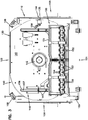
- FIGS. 1-8 illustrate an example communications panel 100 including an example chassis 110 and an example spool arrangement 130.
- the example communications panel 100 has a front 101, a rear 102, a top 103, a bottom 104, a first side 105, and a second side 106.
- Mounting flanges 107 extend outwardly from the first and second sides 105, 106 to enable the communications panel 100 to be secured to a rack or other structure.
- the panel 100 includes a chassis 110 configured to receive at least one spool arrangement 130.
- the chassis 110 is configured to receive only one spool arrangement 130.
- Such as chassis 110 is referred to as a 1RU (rack unit) chassis.
- the chassis 110 can be configured to receive multiple spool arrangements 130.
- the chassis 110 can be configured to receive two spool arrangements 130, three spool arrangements 130, or even more spool arrangements.
- the chassis 110 can include a base 111, a first sidewall 112, a second sidewall 113, and a cover 115 that define an interior 114.
- the chassis interior 114 is accessible through an open front 116 and/or an open rear 117 of the chassis 110.
- the sidewalls 112, 113 of the chassis 10 include guide members that align and retain the spool arrangement 130 within the chassis 110.
- the guide members include guide fingers 121 that extend inwardly from the sidewalls 112, 113.
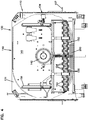
- a guide flange 132 on the spool arrangement 130 slides between the respective sidewall 112, 113 and the guide finger 121 (e.g., see FIG. 2 ).
- the guide members can include guide shelves 122 on which a tray 131 of the spool arrangement 130 can seat (see FIG. 19 ).
- a chassis 110 configured to receive multiple spool arrangements 130 can include multiple rows of guide shelves 122 and guide fingers 121 extending inwardly from the sidewalls 112, 113.
- a cable 200 is wrapped around the spool 140 of a spool arrangement 130 and a free end 201 of the cable 200 extends outwardly from a cable payout port 108 of the panel 100 (see FIG. 2 ).
- the cable 200 can be deployed (i.e., paid out) from the spool 140 by pulling on the free end 201 to rotate the spool 140 about an axis of rotation A R ( FIG. 2 ).
- the spool 140 rotates relative to the tray 131 while the spool arrangement 130 is disposed within the chassis 110.
- the panel 100 can include multiple payout ports 108.
- the free end 201 can be routed through any one of the payout ports 108 to unwind the cable 200 from the spool 140.
- the payout ports 108 can be located at rear corners of the panel 100. In other examples, the payout ports 108 can be located anywhere on the chassis 110.
- a second end of the cable 200 is terminated at the rear ports 154 of one or more optical adapters 153 coupled to the spool 140.
- the cable 200 can include multiple fibers each having a connectorized end plugged into one of the rear ports 154.
- the connectorized ends are disposed in the rear ports 154 before paying out the cable 200.
- the connectorized ends remain disposed in the rear ports 154 while the cable 200 is paid out.
- the spool 140 is locked in position relative to the chassis 110 using a spool lock arrangement 134, which will be described in more detail herein.
- the optical adapters define the one or more termination ports 155, which are accessible from the front 101 of the panel 1 00.
- Connectorized optical fibers can be routed to the front 101 of the panel 100 and plugged into the termination ports 155 to connect to the cable 200.
- the spool arrangement 130 includes one or more front bend radius limiters 127 that facilitate routing the optical fibers away from the front 101 of the panel 100.
- the spool arrangement 130 includes a front bend radius limiter 127 at each front corner of the tray 131.
- the front bend radius limiters 127 are forwardly offset from a remainder of the tray 131.
- the front bend radius limiters 127 can be coupled to the chassis 110 instead of to the spool arrangement 130.
- one or more fanouts can be disposed on the spool 140 to separate the optical fibers of the second end of the cable 200 so that the separate optical fibers can be individually connectorized for receipt at the rear ports 154.
- the second end of the cable 200 extends into a termination cassette in which the fiber(s) of the cable 200 are optically coupled to the termination ports 155.
- one or more splices or splitters can be disposed on the spool 140 to connect the cable 200 to the termination ports 155.
- the spool 140 includes a drum 142 extending upwardly from the tray 131.
- One or more flanges 141 extend radially outwardly from the drum 142 to define a storage region 143 at which the cable 200 is wound.
- a lip 133 FIG. 1
- the drum 142 extends further upwardly beyond a top one of the flanges 141 to define a management region 146 of the spool 140.
- the second end of the cable 200 extends from the drum 142, along the management region 146, to the rear ports 154 of the optical adapters 153.
- a sub-cover 145 can be disposed over the top flange 141 to protect the second end of the cable 200 (see FIG. 2 ).
- the optical adapters 153 are movable relative to the spool 140.
- the optical adapters 153 can be mounted to a termination section 152 of a frame 151 to form an adapter arrangement 150 that is configured to slide relative to the spool 140.
- the frame 151 includes guides 156 engage guide members 147 on the spool 140 to direct the movement of the adapter arrangement 150 along the spool 140.
- two guides 156 extend rearwardly from the termination section 152 of the frame 151.
- each guide 156 defines a slot or channel 157 in which a guide member (e.g., a screw) 147 on the spool 140 rides.
- the rearward guides 156 can slide along channels or rails disposed on the spool 140.
- the adapter arrangement 150 moves between a connection position and a payout position.
- the connection position FIG. 3
- the adapter arrangement 150 is disposed sufficiently forward relative to the drum 142 to enable access to the termination ports 155 from the front 101 of the panel 100.
- the payout position is rearward of the connection position.
- the adapter arrangement 150 is positioned to avoid interference with sidewalls 112, 113 of the chassis 110 when the spool 140 rotates relative to the chassis 110.
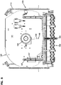
- the adapter arrangement 150 also can be moved to an extended position relative to the spool 140 ( FIG. 8 ). When in the extended position, the rear ports 154 of the adapters 153 are accessible from the front 101 of the panel 100.
- the adapter arrangement 150 can be locked into one or more of the positions relative to the spool 140.
- the adapter arrangement 150 includes an adapter locking arrangement 160 that includes a downwardly extending tab 162.
- the downwardly extending tab 162 aligns with and extends into a first positioning aperture 148 defined in the top flange 141 of the spool 140.
- the downwardly extending tab 162 aligns with and extends into a second positioning aperture 149 defined in the top flange 141.
- the second positioning aperture 149 is located closer to the drum 142 than the first positioning aperture 148.
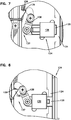
- the adapter locking arrangement 160 (see FIG. 5 ) enables a user to raise the tab 162 relative to the flange 141 to enable movement of the adapter arrangement 150 between positions.
- the adapter locking arrangement 160 includes a support body 161 to which the tab 162 is coupled.
- a spring 163 is mounted to the support body 161 to bias the tab 162 downwardly relative to the support body 161.
- the tab 162 defines slots 165 that glide over guide edges 164 of the support body 161 to maintain proper alignment of the tab 162.
- a release member 167 also is movably mounted to the support body 161.
- the release member 167 can include a grip surface 169 ( FIG. 5 ) configured to facilitate grasping and manipulation of the release member 1 67 by the user.
- movement of the release member 167 forwardly relative to the support body 161 raises the tab 162 to disengage the adapter arrangement 150 from the positioning apertures.
- movement of the release member 167 rearwardly relative to the support body 161 raises the tab 162 to disengage the adapter arrangement 150 from the positioning apertures.
- movement of the release member 167 in either the forward or rearward direction relative to the support body 161 raises the tab 162 to disengage the adapter arrangement 150 from the positioning apertures.
- the release member 167 is slidingly mounted to the support body 161.
- the release member 167 includes a first camming surface 168a that is configured to engage a first cam follower surface 166a of the tab 162 when the release member 167 is moved (e.g., forwardly) relative to the support body 161.
- the release member 167 includes a second camming surface 168b that is configured to engage a second cam follower surface 166b of the tab 162 when the release member 167 is moved (e.g., rearwardly) relative to the support body 161.
- the cam follower surfaces 166a, 166b of the tab 162 ride up the respective camming surfaces 168a, 168b of the release member 167 during movement of the release member 167, thereby raising the tab 162 relative to the support member 161.
- the spool lock arrangement 134 includes a lock bar 135 mounted to a support member 136.
- the lock bar 135 aligns with an aperture 124 defined in the chassis 110 when the spool arrangement 130 is disposed within the chassis 110. Extending the lock bar 135 into the aperture 124 inhibits rotation of the spool 140 relative to the chassis 110.
- the lock bar 135 is biased towards the extended position. Accordingly, the spool 140 automatically locks relative to the chassis 110 when the spool arrangement 130 is disposed within the chassis 110.
- the spool lock arrangement 134 includes a releasing arrangement 137 that includes a lever arm 138 coupled to the lock bar 135. Pivoting (or otherwise moving) the lever arm 138 between first and second positions extends and retracts the lock bar 135.
- the lever arm 138 defines an engagement surface 139 at one end. Moving the adapter arrangement 150 to the payout position causes the release member 158 to press against the engagement surface 139, thereby moving the lever arm 138 to retract the lock bar 135 (see FIG. 7 ). Moving the adapter arrangement 150 to the connection position moves the release member 158 sufficient to enable the lever arm 138 to return to the first position, thereby extending the lock bar 135 ( FIG. 6 ).
- a user manipulates the release member 167 of the adapter locking arrangement 160 to release the tab 162 from the first positional aperture 148.
- the user slides the adapter arrangement 150 from the connection position to the payout position and allows the tab 162 to engage with the second positional aperture 149.
- the spool lock arrangement 134 is automatically released when the adapter arrangement 150 is moved to the payout position.
- the user pays out the cable 200 by pulling on the free end 201, thereby rotating the spool 140 within the chassis 110.
- the user manipulates the release member 167 of the adapter locking arrangement 160 to release the tab 162 from the second positional aperture 149.
- the user slides the adapter arrangement 150 from the payout position to the connection position and allows the tab 162 to engage with the first positional aperture 148.
- the spool lock arrangement 134 is automatically activated (e.g., by a spring) when the adapter arrangement 150 is moved to the connection position, thereby locking the spool 140 against rotational movement relative to the chassis 110.
- the panel 100 can include circuitry to enable data (e.g., physical layer information) to be transferred from optical connectors received at the termination ports 155, through the panel 100, to a data management network.
- the circuitry includes tray circuitry 190 including media reading interfaces electrically coupled to a tray connector 196.
- the circuitry includes chassis circuitry 170 including a controller board 171 that is electrically coupled to a tray port 179 that is configured to receive the tray connector 196 to connect the spool arrangement 130 to the data management network.
- FIGS. 9-12 illustrate example tray circuitry 190 that is configured to provide data obtained from connectors received at the termination ports 155 to the tray connector 196.
- the tray circuitry 190 includes media reading interface arrangements disposed at the optical adapters 153.
- the media interface arrangements include one or more contact members coupled to a circuit board at the optical adapter 153.
- Some example optical adapters 153 and media reading interface arrangements are disclosed in U.S. Patent No. 8,690,593 .
- Other example optical adapters 153 and media reading interface arrangements are disclosed in U.S. Patent Application Serial No. 14/169,912, filed January 31, 2014 , and titled "Optical Assemblies with Managed Connectivity,".
- the tray circuitry 190 also includes intermediate circuit boards carried by the termination section 152 of the frame 151.
- the intermediate circuit boards include adapter board connectors 191 that interface with connectors of the media interface arrangements.
- the intermediate circuit boards also include cable connectors 192.
- a flexible tray cable 194 has a first end 195 plugged into the cable connector 192 and an opposite second end terminated by the tray connector 196.
- the flexible tray cable 194 has a first end 195 that connects to an intermediate flexible tray cable at a frame port 193.
- the intermediate flexible cable extends between the frame port 193 and the cable connector 192.
- the frame 151 of the adapter arrangement 150 defines a recessed channel 159 in which a portion of the flexible tray cable 194 or the intermediate cable can be disposed.
- the recessed channel 159 is defined at a bottom of the frame 151 in the termination section 152.
- a single circuit board connects to all of the adapter media reading interfaces carried by the frame 151.
- the flexible tray cable 194 has one first end 195 that couples to a single cable connector 192.
- the frame 151 carries multiple intermediate circuit boards that each connect to some of the media reading interfaces.
- each intermediate circuit board has a cable connector 192 and the flexible tray cable 194 has multiple first ends 195 that each couple to one of the cable connectors 192.
- the flexible tray cable 194 is routed so that the tray connector 196 is disposed at a stowed location 197 on the frame 151.
- the tray connector 196 can be attached to the frame 151 towards the front of the frame 151 so that the tray connector 196 is accessible to a user through the open front 116 of the chassis 110.
- the stowed location 197 is defined at one side of the termination section 152 towards the front. Retaining tabs 198 are provided along the side of the frame 151 to aid in holding the flexible tray cable 194.
- One or more routing fingers 199 may be provided by the rearward guide 156 to aid in guiding the flexible tray cable 194 from the frame port 193 to the stowed location 197.
- the tray connector 196 is attached to the frame 151 at the stowed location 197 while the spool arrangement 130 is mounted to the chassis 110 and while the cable 200 is deployed.
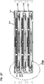
- FIGS. 13-18 illustrate example chassis circuitry 170 including a controller board 171 that mounts to a chassis and a tray port 179 that is electrically coupled to the controller board 171.
- the controller board 171 includes a circuit board having a board connector 172, a power port 173 at which power is received, and a network port 174 at which the board connects to the data management network.
- the controller board 171 also includes one or more status indicators (e.g., light indicators).
- the tray port 179 is disposed at the open front 116 of the chassis 110.
- a chassis adapter 178 can be disposed on the second sidewall 113 at the open front 116 of the chassis 110.
- the user can access the tray connector 196 through the open front 116 of the chassis 110, remove the tray connector 196 from the stowed location 197 on the adapter frame 151, and plug the tray connector 196 into the tray port 179. Plugging the tray connector 196 into the tray port 179 connects the media reading interfaces of the corresponding spool arrangement 130 to the controller board 171.
- the controller board 171 includes an electronic controller or processor that reads/writes connector information at the termination ports 155 via the media reading interfaces.
- the spool arrangement 130 is structured to facilitate routing of the tray connector 196 to the tray port 179.
- the spool arrangement 130 includes a bend radius limiter 189 disposed at a front (e.g., adjacent the front bend radius limiters 127).
- the radius limiter 1 89 is shaped to bend a forwardly extending cable towards the rear 102 of the panel 100.
- the user can remove the tray connector 196 from the frame 151, pull the tray connector 196 forwardly of the adapter arrangement 150, wrap the flexible cable 194 around the radius limiter 189, and plug the tray connector 196 into a forwardly facing tray port 179.
- the adapter arrangement 150 can be pulled to the extended position to facilitate access to the tray connector 196.
- the chassis 110 is configured to receive multiple spool arrangements 130.
- the chassis 110 includes multiple tray ports 179 (e.g., at the open front 116 of the chassis 110).
- Each spool arrangement 130 includes a corresponding tray connector 196 that is plugged into a corresponding one of the tray ports 179 to connect the media reading interfaces of the spool arrangement 130 to the data network.
- the same controller board 171 is electrically coupled to the media reading interfaces of multiple spool arrangements 130.
- the media reading interfaces are coupled to the data network via the network port 174 of the controller board 171.
- the controller board 171 is mounted to the chassis 110 so that the power port 173 and the network port 174 are disposed towards the open front 116 of the chassis 110.
- the controller board 171 is mounted to the first sidewall 112 and the chassis adapter 178 is mounted to the second sidewall 113.
- a flexible chassis cable 182 ( FIG. 14 ) connects the controller board 171 and the tray port 179.
- the chassis cable 182 is routed along a rear 102 of the chassis 110 and up the second sidewall 113 of the chassis 110 to the tray port 179 via a routing channel 186 as will be described in more detail herein.
- one or more guide members 175 are coupled to the chassis 110 to receive the controller board 171.
- a first guide member 175 is coupled to the first sidewall 112 of the chassis 110 and a second guide member 175 is coupled to the cover 115 of the chassis 110 (see FIG. 17 ).
- the controller board 171 slides along the guide members 175 to mount the controller board 171 within the chassis 110.
- the controller board 171 includes a flexible tab or latch arm 176 that engages with an inner shoulder 177 defined by one of the guide members 175 to secure the controller board 171 within the chassis 110 (see FIGS. 15 and 16 ).
- the controller board 171 plugs into a memory board 180 that is mounted within a rear of the chassis 110.
- the board connector 172 of the controller board 171 may slide into a connector socket of the memory board 180.
- the memory board 180 stores data about the panel 100 (e.g., the number of spool arrangements 130 that the chassis 110 is configured to hold, a unique identification designation of the panel/chassis 110, etc.).
- the memory board 180 defines one or more cable ports 181.
- the memory board 180 defines a cable port 181 for each spool arrangement 130 that the chassis 110 is configured to receive.
- the memory board 180 defines a cable port 181 for tray port 179 defined by the chassis circuitry 170.
- One or more chassis cables 182 extend between the memory board 180 and the chassis adapter(s) 178 to connect each tray port 179 to the controller board 171.
- a bridge 186 extends across the rear of the chassis 110 to support the one or more cables 182.
- the bridge 186 defines an aperture 187 through which the cables 182 can exit the bridge 186 and enter a guide trough 188 that extends along an interior of the second sidewall 113.
- the guide trough 188 routes the cable 182 to the chassis adapter 178.
- the guide trough 188 carries the chassis adapter 178.
- the controller board 171 and the bridge 186 are mounted to the cover 115 of the chassis 110 and the guide trough 188 is mounted to the sidewall 113 of the chassis 110.
- each guide trough 188 is mounted to the sidewall 113.
- Each guide trough 188 is mounted over respective guide members structured to retain a respective spool arrangement 130.
- a single controller board 171 and a single bridge 186 are utilized in each chassis 110 even when the chassis 110 receives multiple spool arrangements 130.
- multiple chassis cables 182 extend over the bridge 186 from a respective cable port 181 of the memory board 180 to the second sidewall 113. At the second sidewall 113, each of the chassis cables 182 is routed into one of the guide troughs 188.
- a first chassis cable 182 can be routed over the bridge 186, through the aperture 187, and into a top guide trough 188.
- Second and third chassis cables 182 extend along the bridge 186, through the bridge aperture 187, and through an aperture defined in the second sidewall 113 to exit the chassis interior 114.
- the second and third chassis cables 182 are routed along an exterior of the sidewall 113 until reaching a respective aperture in the sidewall 113.
- Each of the chassis cables 182 is routed back into the chassis interior 114 and into a respective guide trough 188.
- a flange or cover 128 can be mounted to the exterior of the sidewall 113 over the chassis cables 182 to protect the chassis cables 182 (see FIG. 19 ).
- the chassis and tray circuitry can be grounded to the chassis 110, which can be grounded via a grounding wire to the rack, cabinet, or other surrounding structure.
- the controller board 171 includes a spring clip that engages a conductive surface of the chassis cover 115 (e.g., conductive tape laid on a bare metal surface of cover).
- the spool arrangement 130 can be grounded to the chassis 110 by providing a metal spring clip at the bottom flange 141 of the spool 140 that contacts a conductive surface of the tray 131. The tray 131 contacts the chassis 110 when mounted within the chassis 110.
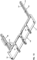
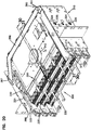
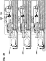
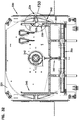
- FIGS. 20-38 illustrate another example communications panel 300 including an example chassis 310 and example spool arrangements 330.
- the chassis 310 can be sized to receive one, two, three, four, or more spool arrangements 330.
- the chassis 310 is configured to receive three spool arrangements 330.
- the chassis 310 is substantially similar to the chasses shown in FIGS. 1-19 .
- a cover has been removed from the chassis 310 to allow viewing of the interior of the chassis 310.
- the example chassis 310 can include a base 311, a first sidewall 312, a second sidewall 313, and a cover that define an interior 314 accessible through an open front 316 and/or an open rear 317.
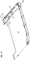
- the sidewalls 312, 313 of the chassis 310 include guide members 320 that align and retain the spool arrangements 330 within the chassis 310.
- the guide members 320 define one or more levels at which a spool arrangement 330 can be mounted.
- the guide members 320 include guide fingers 321 and/or guide shelves 322 that extend inwardly from the sidewalls 312, 313 (e.g., see FIG. 21 ).
- a guide flange 332 on the spool arrangement 330 slides over at least some of the guide shelves 322 and between at least some of the guide fingers 321 and the respective sidewall 312, 313 (e.g., see FIG. 20 ).
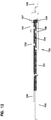
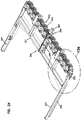
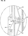
- FIG. 23 illustrates one example spool arrangement 330 suitable for mounting in the chassis 310 (see FIG. 20 ).
- Each spool arrangement 330 includes a spool 340 and at least one optical termination port 355 that rotates in unison with the spool 340.
- a cable 200 can be wound around the spool 340.
- a connectorized end of the cable 200 can be optically coupled to the termination port 355.
- one or more optical adapters are coupled to the spool 340 to rotate in unison.
- multiple connectorized ends of the cable 200 can be plugged into rear ports of optical adapters 353 that interface with front ports 355 of the optical adapters.
- the optical adapters 353 can be mounted to a termination section 352 of a frame 351 to form an adapter arrangement 350 that is configured to slide relative to the spool 340 as will be discussed in more detail herein.
- the panel 300 can include circuitry to enable data (e.g., physical layer information) to be transferred from optical connectors received at the termination ports 355, through the panel 300, to a data management network.
- the circuitry includes tray circuitry 390 including media reading interfaces electrically coupled to a tray connector 393.
- the circuitry includes chassis circuitry 370 including a controller board 371 that is electrically coupled to one or more cables 382. Each cable 382 can be selectively routed to the tray connector 393 of a spool arrangement 330 to connect the spool arrangement 330 to the data management network.
- the controller board 371 plugs into a memory board 380 that is mounted within a rear of the chassis 310.
- a power port 373 and a network port 374 are coupled to the controller board 371 and accessible towards the front 316 of the chassis 310.
- the power port 373 and network port 374 are shown schematically in FIG. 20 .
- the memory board 380 stores data about the panel 300 (e.g., the number of spool arrangements 330 that the chassis 310 is configured to hold, a unique identification designation of the panel/chassis 310, etc.).
- the memory board 380 defines one or more cable ports 381.
- the memory board 380 defines a cable port 381 for each spool arrangement 330 that the chassis 310 is configured to receive.
- a respective cable 382 is routed from each cable port 381 towards the front 316 of the chassis 310.
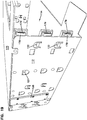
- a bridge 386 extends across the rear of the chassis 310 to support the one or more cables 382 connected to the memory board cable ports 381.
- the bridge 386 defines an aperture 387 through which the cables 382 can exit the bridge 386 at the second sidewall 313 of the chassis 310.
- one or more retaining fingers 388 extend inwardly from the second sidewall 313 to define a cable passage from the bridge 386 towards the front 316 of the chassis 310.
- the cable 382 can be routed through a guide trough (e.g., guide trough 188) attached to the sidewall 313 towards the front 316 of the chassis 310.
- the controller board 371 and the bridge 386 are mounted to the cover of the chassis 310 and the retaining fingers 388 is mounted to the sidewall 313 of the chassis 310.
- one or more cables 382 exit the chassis 310 when exiting the bridge 386.
- the second sidewall 313 may define an aperture 325 through which one or more of the cables 382 can exit the chassis 310 (see FIG. 22 ).
- One or more cables 382 can be routed along an exterior of the second sidewall 313 to other levels of guide members 320 within the chassis.
- the second sidewall 313 may define additional apertures 325 through which one or more cables 382 can enter the chassis 310 to access guide members 320 at different levels within the chassis 310 (e.g., see FIG. 21 ).
- a flange 328 can be mounted to the exterior of the second sidewall 313 to cover the apertures 325 and the portions of the cables 382 extending outside the chassis 310 (e.g., see FIG. 22 ).
- the controller board 371, memory board 380, and bridge 386 mount to a cover of the chassis 310. In the example shown in FIG. 20 , however, the cover is removed from view while the controller board 371, memory board 380, and bridge 386 remain in position relative to a remainder of the chassis 310 for ease in viewing. In other implementations, the controller board 371, memory board 380, and bridge 386 can be mounted to sidewalls of the chassis 310.
- example tray circuitry 390 includes media reading interface arrangements disposed at the optical adapters 353.
- the media interface arrangements include one or more contact members coupled to a circuit board at the optical adapter 353.
- Some example optical adapters 353 and media reading interface arrangements are disclosed in U.S. Patent No. 8,690,593 .
- Other example optical adapters 353 and media reading interface arrangements are disclosed in U.S. Patent Application Serial No. 14/169,912 .
- the tray circuitry 390 also includes a circuit board arrangement 394 carried by the termination section 352 of the frame 351.
- the circuit board arrangement 394 includes one or more adapter board connectors that interface with connectors of the media interface arrangements.
- the circuit board arrangement 394 also includes a tray connector 393 that is electrically connected to the media reading interface arrangements through the circuit board arrangement 394.
- the circuit board arrangement 394 is disposed at a bottom of the frame 351 and the tray connector 393 faces upwardly from the frame 351.
- the tray connector 393 is located at a side of the frame 351 that faces the second sidewall 313 of the chassis 310.
- a connectorized end 384 of the cable 382 can be stowed within the chassis 310 until the spool arrangement 330 is installed and the cable 200 is deployed from the spool arrangement 330.
- the cable 382 can be routed from the chassis 310 to the tray connector 393 after the cable 200 is deployed.
- a user can slide the spool arrangement 330 along the guides 320, deploy the cable 200 from the spool arrangement 330 as will be described herein, grasp the connectorized end 384 of the cable 382 from the front of the chassis 310, and plug the connectorized end 384 into the tray connector 393 of the spool arrangement 330.
- a cable 382 routed through a top level of cable guides 320 is routed to a top-most spool arrangement 330.
- Other levels of cable guides 320 are provided for additional spool arrangements 330 as appropriate.
- the optical adapters 353 are movable relative to the spool 340.
- the optical adapters 353 can be carried by the adapter arrangement 350 that is configured to slide relative to the spool 340.
- the frame 351 includes guides 356, 357 that engage guide members 345 on the spool 340 to direct the movement of the adapter arrangement 350 along the spool 340.
- the guide members 345 of the spool 340 define channels 346 along which the guides 356, 357 can slide.
- horizontal guides 356 extend outwardly from opposite sides of the frame 351 and vertical guides 357 extend upwardly from the frame 351.
- the adapter arrangement 350 moves between a connection position and a payout position.
- the connection position When in the connection position, the adapter arrangement 350 is disposed sufficiently forward relative to the drum 342 to enable access to the termination ports 355 from the front of the panel 300.
- the payout position is rearward of the connection position.
- the adapter arrangement 350 When in the payout position, the adapter arrangement 350 is positioned to avoid interference with sidewalls 312, 313 of the chassis 310 when the spool 340 rotates relative to the chassis 310.
- the adapter arrangement 350 also can be moved to an extended position relative to the spool 340. When in the extended position, rear ports of the adapters 353 are accessible from the front of the panel 300.
- the adapter arrangement 350 can be locked into one or more of the positions relative to the spool 340 using an adapter locking arrangement 360.
- the adapter arrangement 350 can be locked into the connection position.
- the adapter arrangement 350 can be locked into the payout position.
- the adapter locking arrangement 360 includes a downwardly extending tab 362 that can be raised and lowered.
- the downwardly extending tab 362 aligns with and extends into a first positioning aperture 348 at the spool 340 (see FIG. 29 ).
- the downwardly extending tab 362 aligns with and extends into a second positioning aperture 349 defined at the spool 340 (see FIG. 29 ).
- the second positioning aperture 349 is located closer to the drum 342 than the first positioning aperture 348.
- the tab 362 is raised out of the positioning aperture 348, 349 to enable movement of the adapter arrangement 350 between positions.
- the adapter locking arrangement 360 includes a support body 361 to which the tab 362 is coupled.
- a spring 363 is mounted to the support body 361 to bias the tab 362 downwardly relative to the support body 361. Accordingly, the tab 362 automatically latches to the positioning apertures 348, 349 when the tab 362 aligns with the positioning apertures 348, 349.
- a release member 367 also is movably (e.g., slideably) mounted to the support body 361.
- the release member 367 can include a grip surface 369 configured to facilitate grasping and manipulation of the release member 367 by the user.
- the release member 367 includes a camming surface 366 that is configured to engage a cam follower 365 of the tab 362 when the release member 367 is moved in a first direction (e.g., forwardly) relative to the support body 361. Moving the release member 367 moves the camming surface 366 relative to the cam follower 365 so that the cam follower 365 rides up the camming surface 366, thereby raising the tab 362. In certain examples, the camming surface 366 extends upwardly in a rearward direction relative to the tab 362. In such examples, forward movement of the release member 367 raises the tab 362 to disengage the adapter arrangement 350 from the positioning apertures 348, 349.
- a first direction e.g., forwardly
- the release member 367 includes camming surfaces that extend upwardly in both directions so that movement of the release member 367 forwardly or rearwardly will raise the tab 362. In other implementations, however, the release member 367 does not define a camming surface that extends upwardly in a forward direction from the tab 362. Rather, the release member 367 defines a shoulder 364 that is positioned sufficiently oblique to the tab 362 so that the tab 362 cannot cam up the shoulder 364 (e.g., see FIG. 31 ). In such implementations, the abutment between the tab 362 and the shoulder 364 inhibits rearward movement of the release member 367 by a user.
- a user cannot move the adapter arrangement 350 from the connection position to the payout position by pushing rearwardly on the release member 367. Rather, the user would pull forwardly on the release member 367 to raise the tab 362 out of the first positioning aperture 348 and separately push the frame 351 rearwardly towards the drum 342. To move the adapter arrangement 350 from the payout position to the connection position, the user would pull forwardly on the release member 367 to raise the tab 362 out of the second positioning aperture 349 and continue pulling the release member 367 forwardly away from the drum 342.
- a ramp 347 is disposed at an opposite of the first positioning aperture 348 from the second positioning aperture 349.
- the ramp 347, the first positioning aperture 348, and the second positioning aperture 349 are aligned in a forward-rearward direction.
- the tab 362 will cam up the ramp 347 when the adapter arrangement 350 is moved rearwardly from the extended position to the connection position. Accordingly, a user can move the adapter arrangement 350 from the extended position to the connection position by pushing rearwardly on the release member 367 (or pulling forwardly on the release member and pushing rearwardly on the frame 351).
- the spool lock arrangement 334 includes a lock bar 335 mounted to a lock bar support member 336.
- a support member 345 defines both the lock bar support member 336 and one of the guide members 346 of the spool 340.
- two support members 345 are mounted to opposite sides of the spool 340 to provide the guide members 346.
- a lock bar 335 can be mounted to the lock bar support member 336 of one of the support members 345.
- the lock bar 335 aligns with an aperture 324 ( FIG. 21 ) defined in the chassis 310 when the spool arrangement 330 is disposed within the chassis 310. Extending the lock bar 335 into the aperture 324 inhibits rotation of the spool 340 relative to the chassis 310 (see FIG. 20 ). Retracting the lock bar 335 from the aperture 324 releases the spool 340 to rotate relative to the chassis 310.
- the lock bar 335 is biased towards the extended position. Accordingly, the spool 340 automatically locks relative to the chassis 310 when the spool arrangement 330 is disposed within the chassis 310.
- the lock bar 335 includes a peg 337 that moves unitarily with the lock bar 335.
- the spool lock arrangement 334 includes a releasing arrangement 338 coupled to the frame 351 of the adapter arrangement 350 (e.g., see FIGS. 32 and 34 ).
- the releasing arrangement 338 defines a cam surface 339.
- the peg 337 rides along the cam surface 339 when the frame 351 is slid relative to the spool 340.
- the cam surface 339 ramps inwardly relative to the spool 340 as the cam surface 339 extends towards the front 316 of the chassis 310. Accordingly, the cam surface 339 causes the peg 337 to move inwardly relative to the spool 340 as the cam surface 339 moves rearwardly relative to the peg 337.
- FIGS. 32 and 33 illustrate the frame 351 in the connection position.
- the tab 362 of the adapter locking arrangement 360 is disposed within the first positioning aperture 348.
- the releasing arrangement 338 is positioned relative to the peg 337 to not interfere with the biasing of the lock bar 335. Accordingly, the lock bar 335 is disposed in the extended position.
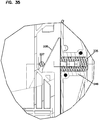
- FIGS. 34 and 35 illustrate the frame 351 in the payout position.
- the tab 362 of the adapter locking arrangement 360 is disposed within the second positioning aperture 349.
- the peg 337 has cammed inwardly along the cam surface 339 so that the lock bar 335 is disposed in the retracted position.
- a user manipulates the release member 367 of the adapter locking arrangement 360 to release the tab 362 from the first positional aperture 348.
- the user slides the adapter arrangement 350 from the connection position to the payout position and allows the tab 362 to engage with the second positional aperture 349.
- the spool lock arrangement 334 is automatically released when the adapter arrangement 350 is moved to the payout position.
- the user pays out the cable 200 by pulling on the free end 201, thereby rotating the spool 340 within the chassis 310.
- the user manipulates the release member 367 of the adapter locking arrangement 360 to release the tab 362 from the second positional aperture 349.
- the user slides the adapter arrangement 350 from the payout position to the connection position and allows the tab 362 to engage with the first positional aperture 348.
- the spool lock arrangement 334 is automatically activated (e.g., by a spring) when the adapter arrangement 350 is moved to the connection position, thereby locking the spool 340 against rotational movement relative to the chassis 310.
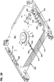
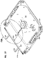
- FIGS. 36-38 illustrate an example designation member 118 that can be coupled to the spool arrangement 330.
- the designation member 118 is coupled to the spool arrangement 330 after at least some of the cable 200 has been paid out.
- the designation member 118 includes a lip 333 on which labels for the adapter ports 355 can be disposed.
- the lip 333 aids in retaining the cable 200 on the spool 340.
- One or more support fingers 119 extend forwardly of the lip 333 to aid in routing fibers or cables to the adapter ports 355.
- the designation member 118 is configured to latch to the spool arrangement 330.
- the designation member 118 includes flexible fingers 327 at opposite ends.
- Each flexible finger 327 includes a latch button 329a and a push tab 329b.
- the latch button 329a is configured to snap into an opening defined by the tray 331 of the spool arrangement 330 (e.g., see FIG. 38 ).
- the push tab 329b is configured to deflect the flexible finger 327 sufficient to remove the latch button 329a from the opening when pushed by a user (e.g., see FIG. 36 ).
- the designation member 118 is configured to aid in locking the spool 340 in a rotational position relative to the tray 331 of the spool arrangement 330.
- a bottom flange 341 of the spool 340 defines a notch 343 and the designation member 118 includes a tab 323 configured to extend into the notch 343 when the designation member 118 is mounted to the tray 331. Interaction between the tab 323 and the notch 343 inhibits rotation of the spool 340 when the designation member 118 is mounted to the tray 331.
- the tray 331 also defines the notch 343 into which the tab 323 extends.
- the spool flange 341 also defines cutout shoulders 344 at an open side of the notch 343.
- the tab 323 of the designation member 118 includes wings 326 that are sized to fit in the cutout shoulders 344 when the designation member 118 is mounted to the tray 331.
- the designation member 118 cannot fit on the tray 331 until at least some of the cable 200 has been paid out. Accordingly, the designation member 118 does not block rotation of the spool 340 before paying out the cable 200.
Description
- Communications (e.g., telecommunications) cables can be stored on, delivered on, and deployed by spools. A communications cable is typically wound on the spool at a factory that produced the cable. Upon delivery to an installation site, the cable can be unwound from the spool and deployed. For example, a connectorized end of the cable can be routed and coupled to a cabinet, distribution hub, or other network location or to a piece of communications equipment. An opposite end of the cable can be terminated at one or more ports on the spool. The spool can be disposed within a cabinet, rack, or other enclosure. Improvements are desired.
US 2001/0019002 A1 relates to a retractable cable reel and discloses a communications panel according to the preamble ofclaim 1. .US2012/0063735 A1 relates to a fiber distribution terminal.US20130287357 A1 relates to a slidable fiber optic connection module with cable slack management.US 2013/0094828 A1 relates to a fiber optic distribution terminal.US 2011/0267794 A1 relates to a communications bladed panel system. - The present invention provides a communications panel as defined in
claims 1 to 15. Some aspects of the disclosure are directed to a communications panel including a chassis defining an interior; chassis circuitry coupled to the chassis and electrically connected to a data management network; a spool arrangement disposed within the chassis; and spool circuitry including media reading interfaces coupled to the optical adapters. The spool arrangement includes a rotatable cable spool and optical adapters coupled to the cable spool to rotate in unison with the cable spool. The spool circuitry being configured to be unconnected to the chassis circuitry while a cable is being paid out from the cable spool and to be connected to the chassis circuitry when the cable has been paid out from the cable spool. - In some implementations, the spool circuitry includes a flexible cable electrically coupled to the media reading interfaces. The flexible cable has a free end that is movable between a stowed position and a connected position. The spool circuitry is unconnected to the chassis circuitry when the free end is disposed in the stowed position. The spool circuitry is connected to the chassis circuitry when the free end is disposed in the connected position.
- In examples, the free end is retained at a fixed location on the spool arrangement when disposed in the stowed position. The free end is plugged into a tray port disposed on the chassis when in the connected position. In an example, a connector holder is disposed at an exterior of the chassis. The connector holder defines the tray port and defining a rearward facing port. The chassis circuitry includes a controller board arrangement and a chassis cable having a first end coupled to the controller board arrangement and a second end plugged into the rearward facing port of the connector holder.
- In other implementations, the spool circuitry includes a circuit board electrically coupled to the media reading interfaces. The circuit board includes a circuit board connector accessible at one side of the spool arrangement. In examples, the chassis circuitry includes a controller board arrangement and a chassis cable having a first end coupled to the controller board arrangement and a second end configured to be selectively connected to the circuit board connector of the spool circuitry.
- In certain examples, the chassis circuitry includes electronic memory storing data pertaining to the communications panel.
- In certain implementations, a second spool arrangement is disposed in the chassis. The second spool arrangement includes a second cable spool. Additional spool circuitry includes media reading interfaces coupled to optical adapters of the second spool arrangement. The additional spool circuitry is configured to be unconnected to the chassis circuitry while a second cable is being paid out from the second cable spool and to be connected to the chassis circuitry when the second cable has been paid out from the second cable spool.
- In examples, the chassis circuitry includes multiple tray ports and each spool arrangement includes a respective flexible cable that is configured to selectively plug into one of the tray ports to connect the respective spool arrangement to the data management network. In examples, the chassis circuitry includes multiple cables having free ends, each spool arrangement includes a respective circuit board connected to the media reading interfaces of the spool arrangement and including a tray connector, and the free end of each of the cables can be plugged into the tray connector of one of the spool arrangements.
- In certain implementations, the spool arrangement includes an adapter arrangement mounted to the cable spool. The adapter arrangement carries the optical adapters that are coupled to the cable spool. The adapter arrangement is configured to slide relative to the cable spool between a connection position and a payout position.
- Other aspects of the disclosure are directed to a communications panel including a chassis including a body and a cover that define a chassis interior; a controller board arrangement mounted to the cover within the interior of the chassis; and a chassis cable having a first end and an opposite second end. The body includes first and second opposing sidewalls extending between a base and the cover. The sidewalls also extend between an open front and a rear of the chassis. The controller board arrangement is mounted to the chassis through the open front of the chassis. The first end being electrically is coupled to the controller board arrangement. The chassis cable is routed along the chassis so that the second end is disposed at the open front of the chassis.
- In certain implementations, the first end of the chassis cable is electrically coupled to the controller board arrangement at a rear of the chassis. At least one guide member is attached to the first sidewall of the chassis defines a passage through which the chassis cable is routed from the rear of the chassis to the open front of the chassis so that the second end of the chassis cable is disposed at the first sidewall. In examples, the guide member includes a trough defining the channel. In examples, the guide member includes at least two retaining fingers.
- In certain implementations, the controller board arrangement is disposed at the second sidewall of the chassis. In examples, a bridge member is coupled to the cover within the interior of the chassis. The bridge member supports and routes conductors of the chassis cable to the second sidewall at the rear of the chassis.
- In certain implementations, a memory board is mounted to the cover within the interior of the chassis. The memory board is electrically coupled to the controller board arrangement at the rear of the chassis. The first end of the chassis cable is electrically coupled to the controller board arrangement via the memory board. In examples, the memory board defines a plurality of connection ports. The chassis cable includes a plurality of chassis cables each having a first end and a second end. The first ends of the chassis cables are coupled to the connection ports of the memory board. The second ends of the chassis cables are disposed at the open front of the chassis.
- In an example, the first sidewall of the chassis defines a plurality of apertures towards the rear of the chassis. A first of the chassis cables is routed along a chassis interior towards the open front of the chassis, and a second of the chassis cables exits the chassis interior through a first of the apertures, is routed along an exterior of the first sidewall, reenters the chassis interior through a second of the apertures, and is routed along the chassis interior towards the open front of the chassis.
- In certain implementations, the controller board arrangement defines a data port and/or a power port at the open front end of the chassis.
- In certain implementations, a tray is configured to mount within the chassis interior. The tray includes data management circuitry coupled to a tray connector to which the second end of the chassis cable can be connected, thereby electrically coupling the data management circuitry of the tray to the controller board arrangement.
- In some examples, the tray connector terminates a tray cable and is releasably coupled to the tray at a stowed location. The tray cable has slack length sufficiently long to enable the tray connector to be released from the tray and to be connected to the second end of the chassis cable at an exterior of the chassis. In other examples, the tray connector is part of a tray circuit board. The chassis cable has sufficient slack length to extend from the chassis to the tray connector on the tray.
- Other aspects of the disclosure are directed to a spool arrangement including a base configured to be mounted within a chassis interior; a spool disposed on the base so that the spool can rotate relative to the base about a rotation axis that extends upwardly from the base; an adapter arrangement mounted to the spool to move in unison with the spool when the spool rotates relative to the base; and data management circuitry disposed on the adapter arrangement so that the data management circuitry moves in unison with the spool when the spool rotates relative to the base. The adapter arrangement includes a frame holding a plurality of optical adapters. The frame is configured to slide relative to the spool between a connection position and a payout position. The connection position is farther forward relative to the base than the payout position. The data management circuitry includes a circuit board coupled to at least some of the optical adapters. The circuit board is electrically coupled to a tray connector accessible at a front of the spool arrangement.
- In certain implementations, the spool includes a drum and at least one flange extending radially outwardly from the drum. The at least one flange defines a first positioning aperture and a second positioning aperture that is spaced rearwardly from the first positioning aperture. The adapter arrangement includes a movable tab that aligns with the first positioning aperture when the adapter arrangement is disposed in the connection position and aligns with the second positioning aperture when the adapter arrangement is disposed in the payout position.
- In examples, the adapter arrangement is configured to also move to an extended position that is farther forward than the connection position. In an example, the at least one flange also defines a ramp configured to move the tab to enable rearward movement of the adapter arrangement from the extended position to the connection position.
- In examples, the movable tab is operatively coupled to a releasing member so that movement of the releasing member raises the movable tab. In an example, pulling the releasing member raises the movable tab out of either of the positioning apertures and pushing the releasing member does not raise the movable tab out of either of the positioning apertures.
- Other aspects of the disclosure are directed to a method of electrically connecting media reading interfaces at optical ports to a data management network. The method includes providing a chassis defining an interior, a controller board arrangement disposed within the interior of the chassis, and a chassis cable having a first end coupled to the controller board arrangement and a second end disposed at an open front of the chassis; installing a spool arrangement within the interior of the chassis; paying out a cable from the spool arrangement; and connecting a free end of the chassis cable to the tray connector. The spool arrangement includes a plurality of optical adapters defining optical ports, a plurality of media reading interfaces at the optical ports, and a tray connector electrically coupled to the media reading interfaces.
- In certain implementations, the method includes plugging a network cable into a data port of the controller board arrangement. The network cable is connected to a data management network.
- In certain implementations, the method includes inserting a second spool arrangement within the interior of the chassis; paying out another cable from the second spool arrangement; and connecting a free end of a second chassis cable to the second tray connector. The second spool arrangement includes a plurality of optical adapters defining optical ports, a plurality of media reading interfaces at the optical ports, and a second tray connector electrically coupled to the media reading interfaces of the second spool arrangement.
- In certain implementations, the method includes mounting a designation member to the spool arrangement to aid in rotationally locking a spool of the spool arrangement.
- Other aspects of the disclosure are directed to a communications panel including a chassis; and a spool arrangement disposed within the interior of the chassis. The chassis includes first and second sidewalls extending between a base and a cover and extending between an open front and a rear. The first sidewall defines an aperture. The spool arrangement includes a tray, a spool rotatably disposed on the tray, a spool locking arrangement including a lock bar aligned with the aperture of the first sidewall of the chassis when the spool arrangement is disposed in the chassis, and an adapter arrangement disposed on the spool. The lock bar is configured to slide between a retracted position and an extended position. The lock bar is biased to the extended position in which the lock bar extends through the aperture. The lock bar is removed from the aperture when disposed in the retracted position. The adapter arrangement is configured to move between a connection position and a payout position. The lock bar is automatically retracted when the adapter arrangement is moved to the payout position. The lock bar is automatically extended when the adapter arrangement is moved to the connection position.
- In certain implementations, the adapter arrangement includes a frame including a leg extending rearwardly from a main section. The main section holds a plurality of optical adapters. The leg is configured to actuate extension and retraction of the lock bar. In some examples, the lock bar is operationally coupled to an arm that moves between a first position and a second position. The arm is biased to the first position. The arm moves the lock bar to the retracted position when the arm moves to the second position. The arm moves the lock bar to the extended position when the arm moves to the first position. The leg is configured to engage the arm to move the arm between the first and second positions as the adapter arrangement moves between the connection position and the payout position, respectively. In other examples, the lock bar includes a peg and the leg defines a camming surface along which the peg rides to extend and retract the lock bar.
- In certain implementations, the spool includes a drum extending upwardly from a flange. The flange defines first and second positioning apertures. The adapter arrangement is mounted to the flange. The adapter arrangement includes a tab that extends downwardly. The tab extends into the first positioning aperture when the adapter arrangement is disposed in the connection position and the tab extends into the second positioning aperture when the adapter arrangement is disposed in the payout position. In examples, the adapter arrangement includes a forwardly extending handle having a free end. Operation of the release mechanism moves the tab of the adapter arrangement between a locked position and a released position.
- Other aspects of the disclosure are directed to a method of installing a panel arrangement including providing a spool arrangement accessible through an open front of a chassis; disposing an adapter arrangement relative to a spool of the spool arrangement in a payout position; paying out a cable from the spool by pulling on a free end of the cable; continuing to rotate the spool until ports of the adapter arrangement align with the open front of the chassis; and locking the spool relative to the chassis by moving the adapter arrangement forwardly from the payout position to a connection position. Paying out the cable causes the spool to rotate. The adapter arrangement rotates in unison with the spool. The adapter arrangement is releasably locked relative to the spool when in the connection position.
- In certain implementations, the method includes disposing the adapter arrangement in the payout position comprises moving the adapter arrangement rearwardly from the connection position to the payout position.
- In certain implementations, the adapter arrangement is releasably locked relative to the spool when disposed in the payout position.
- In certain examples, moving the adapter arrangement forwardly from the payout position to the connection position also includes releasing the adapter arrangement from the payout position by retracting a spring-biased tab of the adapter arrangement from a positioning aperture defined by the spool; and enable the spring-biased tab to enter another positioning aperture defined by the spool when the adapter arrangement is disposed in the connection position.
- In some examples, moving the adapter arrangement forwardly from the payout position to the connection position moves an outwardly extending tab of the adapter arrangement away from a pivot arm of a locking arrangement to release the pivot arm. Releasing the pivot arm enables a lock bar of the locking arrangement to extend.
- In other examples, moving the adapter arrangement forwardly from the payout position to the connection position moves a camming surface relative to a peg of a lock bar to retract the lock bar as the peg rides along the camming surface.
- A variety of additional inventive aspects will be set forth in the description that follows. The inventive aspects can relate to individual features and to combinations of features. It is to be understood that both the forgoing general description and the following detailed description are exemplary and explanatory only and are not restrictive of the broad inventive concepts upon which the embodiments disclosed herein are based,
- The accompanying drawings, which are incorporated in and constitute a part of the description, illustrate several aspects of the present disclosure. A brief description of the drawings is as follows:
-
FIG. 1 is a front perspective view of an example communications panel including a chassis and a spool arrangement in accordance with the principles of the present disclosure; -
FIG. 2 is a rear perspective view of the communications panel ofFIG. 1 with a chassis cover removed for ease in viewing the spool arrangement including a spool and an adapter arrangement; -
FIG. 3 is a top plan view of the communications panel ofFIG. 2 with the adapter arrangement disposed in a connection position; -
FIG. 4 is a top plan view of the communications panel ofFIG. 2 with the adapter arrangement disposed in a payout position; -
FIG. 5 is an enlarged perspective view of a cross-section of part of the adapter arrangement disposed in a connection position; -
FIG. 6 is a top plan view of an example spool lock arrangement disposed in an activated position; -
FIG. 7 is a top plan view of the spool lock arrangement ofFIG. 6 disposed in a released position; -
FIG. 8 is a top plan view of the communications panel ofFIG. 2 with the adapter arrangement disposed in an extended position; -
FIG. 9 is a front perspective view of an example spool arrangement configured to be received within a chassis; -
FIG. 10 is a top perspective view of an example adapter arrangement frame suitable for mounting to a spool and for receiving one or more optical adapters; -
FIG. 11 is a bottom perspective view of the adapter arrangement ofFIG. 10 with a portion of the bottom surface removed to expose cable connectors: -
FIG. 12 is a side elevational view of the adapter arrangement frame ofFIG. 10 with a tray cable schematically shown routed to a stowed location; -
FIG. 13 is a front perspective view of an example chassis and chassis circuitry; -
FIG. 14 is a top plan view of the chassis ofFIG. 13 ; -
FIGS. 15 and 16 are enlarged views of a portion ofFIG. 14 showing the chassis controller board partially and fully received within the chassis, respectively; -
FIG. 17 is a bottom perspective view of an example chassis cover carrying portions of the chassis circuitry; -
FIG. 18 is a top perspective view of an example chassis body carrying other portions of the chassis circuitry; -
FIG. 19 is a perspective view of another example chassis configured to receive multiple spool arrangements; -
FIG. 20 is a front perspective view of another example communications panel including a chassis and a spool arrangement in accordance with the principles of the present disclosure; -
FIGS. 21 and22 are perspective views of an example chassis suitable for use in the communications panel ofFIG. 20 ; -
FIG. 23 is a perspective view of an example spool arrangement suitable for use in the communications panel ofFIG. 20 ; -
FIGS. 24-26 illustrate an example adapter arrangement suitable for use with the spool arrangement ofFIG. 23 ; -
FIG. 27 is a front view of the example communications panel ofFIG. 20 ; -
FIG. 28 is an enlarged view of a portion ofFIG. 27 ; -
FIG. 29 is a perspective view of the spool arrangement ofFIG. 23 with the adapter arrangement removed; -
FIG. 30 is a cross-sectional view of a front portion of the spool arrangement taken along the 30-30 line inFIG. 23 ; -
FIG. 31 is a cross-sectional view of a front portion of the spool arrangement taken along the 31-31 line inFIG. 23 ; -
FIG. 32 is a plan view of a cross-section of a spool arrangement where a top portion of the adapter arrangement, which is disposed in a connection position, has been removed so that a releasing arrangement of the adapter arrangement and a peg of a lock bar are visible; -
FIG. 33 is an enlarged view of a portion ofFIG. 32 ; -
FIG. 34 is similar toFIG. 32 except that the adapter arrangement has been moved to the payout position; -
FIG. 35 is an enlarged view of a portion ofFIG. 34 ; -
FIG. 36 is a perspective view of an example designation member suitable for use with the spool arrangement ofFIG. 23 ; -
FIG. 37 is a perspective view of the spool arrangement ofFIG. 29 with the designation member exploded away from the tray; and -
FIG. 38 is an enlarged view of a portion ofFIG. 37 . - Reference will now be made in detail to exemplary aspects of the present disclosure that are illustrated in the accompanying drawings.
- In general, the disclosure relates to a
communications panel 100, 300 including achassis spool arrangement spool arrangement spool optical termination port spool communications panel 100, 300 so that physical layer information (PLI) stored electronically on optical connectors received at the optical termination ports can be provided to a data management network. -
FIGS. 1-8 illustrate an example communications panel 100 including anexample chassis 110 and anexample spool arrangement 130. The example communications panel 100 has a front 101, a rear 102, a top 103, a bottom 104, afirst side 105, and asecond side 106. Mountingflanges 107 extend outwardly from the first andsecond sides chassis 110 configured to receive at least onespool arrangement 130. In the example shown, thechassis 110 is configured to receive only onespool arrangement 130. Such aschassis 110 is referred to as a 1RU (rack unit) chassis. In other examples, however, thechassis 110 can be configured to receivemultiple spool arrangements 130. For example, thechassis 110 can be configured to receive twospool arrangements 130, threespool arrangements 130, or even more spool arrangements. - For example, the
chassis 110 can include abase 111, afirst sidewall 112, asecond sidewall 113, and acover 115 that define an interior 114. Thechassis interior 114 is accessible through anopen front 116 and/or anopen rear 117 of thechassis 110. In certain implementations, thesidewalls chassis 10 include guide members that align and retain thespool arrangement 130 within thechassis 110. In certain examples, the guide members include guidefingers 121 that extend inwardly from thesidewalls guide flange 132 on thespool arrangement 130 slides between therespective sidewall FIG. 2 ). In other examples, the guide members can include guideshelves 122 on which atray 131 of thespool arrangement 130 can seat (seeFIG. 19 ). For example, achassis 110 configured to receivemultiple spool arrangements 130 can include multiple rows ofguide shelves 122 and guidefingers 121 extending inwardly from thesidewalls - A
cable 200 is wrapped around thespool 140 of aspool arrangement 130 and afree end 201 of thecable 200 extends outwardly from acable payout port 108 of the panel 100 (seeFIG. 2 ). Thecable 200 can be deployed (i.e., paid out) from thespool 140 by pulling on thefree end 201 to rotate thespool 140 about an axis of rotation AR (FIG. 2 ). In some implementations, thespool 140 rotates relative to thetray 131 while thespool arrangement 130 is disposed within thechassis 110. In certain examples, the panel 100 can includemultiple payout ports 108. Thefree end 201 can be routed through any one of thepayout ports 108 to unwind thecable 200 from thespool 140. As shown inFIG. 2 , thepayout ports 108 can be located at rear corners of the panel 100. In other examples, thepayout ports 108 can be located anywhere on thechassis 110. - A second end of the
cable 200 is terminated at therear ports 154 of one or moreoptical adapters 153 coupled to thespool 140. For example, thecable 200 can include multiple fibers each having a connectorized end plugged into one of therear ports 154. In certain examples, the connectorized ends are disposed in therear ports 154 before paying out thecable 200. In certain examples, the connectorized ends remain disposed in therear ports 154 while thecable 200 is paid out. After thecable 200 is deployed, thespool 140 is locked in position relative to thechassis 110 using aspool lock arrangement 134, which will be described in more detail herein. The optical adapters define the one ormore termination ports 155, which are accessible from thefront 101 of thepanel 1 00. - Connectorized optical fibers (e.g., patch cords) can be routed to the
front 101 of the panel 100 and plugged into thetermination ports 155 to connect to thecable 200. In some implementations, thespool arrangement 130 includes one or more frontbend radius limiters 127 that facilitate routing the optical fibers away from thefront 101 of the panel 100. In the example shown, thespool arrangement 130 includes a frontbend radius limiter 127 at each front corner of thetray 131. In certain examples, the frontbend radius limiters 127 are forwardly offset from a remainder of thetray 131. In other examples, the frontbend radius limiters 127 can be coupled to thechassis 110 instead of to thespool arrangement 130. - In some implementations, one or more fanouts can be disposed on the
spool 140 to separate the optical fibers of the second end of thecable 200 so that the separate optical fibers can be individually connectorized for receipt at therear ports 154. In other implementations, the second end of thecable 200 extends into a termination cassette in which the fiber(s) of thecable 200 are optically coupled to thetermination ports 155. In still other implementations, one or more splices or splitters can be disposed on thespool 140 to connect thecable 200 to thetermination ports 155. - The
spool 140 includes adrum 142 extending upwardly from thetray 131. One ormore flanges 141 extend radially outwardly from thedrum 142 to define astorage region 143 at which thecable 200 is wound. A lip 133 (FIG. 1 ) aids in retaining thecable 200 within thestorage region 143. Thelip 133 also can be utilized as a designation plate. In certain implementations, thedrum 142 extends further upwardly beyond a top one of theflanges 141 to define amanagement region 146 of thespool 140. The second end of thecable 200 extends from thedrum 142, along themanagement region 146, to therear ports 154 of theoptical adapters 153. In certain examples, a sub-cover 145 can be disposed over thetop flange 141 to protect the second end of the cable 200 (seeFIG. 2 ). - In some implementations, the
optical adapters 153 are movable relative to thespool 140. For example, theoptical adapters 153 can be mounted to atermination section 152 of aframe 151 to form anadapter arrangement 150 that is configured to slide relative to thespool 140. In certain implementations, theframe 151 includesguides 156 engageguide members 147 on thespool 140 to direct the movement of theadapter arrangement 150 along thespool 140. In certain examples, twoguides 156 extend rearwardly from thetermination section 152 of theframe 151. In an example, eachguide 156 defines a slot orchannel 157 in which a guide member (e.g., a screw) 147 on thespool 140 rides. In other examples, the rearward guides 156 can slide along channels or rails disposed on thespool 140. - In certain examples, the
adapter arrangement 150 moves between a connection position and a payout position. When in the connection position (FIG. 3 ), theadapter arrangement 150 is disposed sufficiently forward relative to thedrum 142 to enable access to thetermination ports 155 from thefront 101 of the panel 100. The payout position is rearward of the connection position. When in the payout position (FIG. 4 ), theadapter arrangement 150 is positioned to avoid interference withsidewalls chassis 110 when thespool 140 rotates relative to thechassis 110. In certain examples, theadapter arrangement 150 also can be moved to an extended position relative to the spool 140 (FIG. 8 ). When in the extended position, therear ports 154 of theadapters 153 are accessible from thefront 101 of the panel 100. - In some implementations, the
adapter arrangement 150 can be locked into one or more of the positions relative to thespool 140. In certain examples, theadapter arrangement 150 includes anadapter locking arrangement 160 that includes a downwardly extendingtab 162. When theadapter arrangement 150 is disposed in the connection position, the downwardly extendingtab 162 aligns with and extends into afirst positioning aperture 148 defined in thetop flange 141 of thespool 140. When theadapter arrangement 150 is disposed in the payout position, the downwardly extendingtab 162 aligns with and extends into asecond positioning aperture 149 defined in thetop flange 141. Thesecond positioning aperture 149 is located closer to thedrum 142 than thefirst positioning aperture 148. - In certain implementations, the adapter locking arrangement 160 (see
FIG. 5 ) enables a user to raise thetab 162 relative to theflange 141 to enable movement of theadapter arrangement 150 between positions. In certain examples, theadapter locking arrangement 160 includes asupport body 161 to which thetab 162 is coupled. Aspring 163 is mounted to thesupport body 161 to bias thetab 162 downwardly relative to thesupport body 161. In an example, thetab 162 definesslots 165 that glide over guide edges 164 of thesupport body 161 to maintain proper alignment of thetab 162. - A
release member 167 also is movably mounted to thesupport body 161. For example, therelease member 167 can include a grip surface 169 (FIG. 5 ) configured to facilitate grasping and manipulation of therelease member 1 67 by the user. In some implementations, movement of therelease member 167 forwardly relative to thesupport body 161 raises thetab 162 to disengage theadapter arrangement 150 from the positioning apertures. In other implementations, movement of therelease member 167 rearwardly relative to thesupport body 161 raises thetab 162 to disengage theadapter arrangement 150 from the positioning apertures. In still other implementations, movement of therelease member 167 in either the forward or rearward direction relative to thesupport body 161 raises thetab 162 to disengage theadapter arrangement 150 from the positioning apertures. - In certain implementations, the
release member 167 is slidingly mounted to thesupport body 161. In certain examples, therelease member 167 includes afirst camming surface 168a that is configured to engage a firstcam follower surface 166a of thetab 162 when therelease member 167 is moved (e.g., forwardly) relative to thesupport body 161. In certain examples, therelease member 167 includes asecond camming surface 168b that is configured to engage a secondcam follower surface 166b of thetab 162 when therelease member 167 is moved (e.g., rearwardly) relative to thesupport body 161. Thecam follower surfaces tab 162 ride up therespective camming surfaces release member 167 during movement of therelease member 167, thereby raising thetab 162 relative to thesupport member 161. - As shown in
FIGS. 3-7 , movement of theadapter arrangement 150 relative to thespool 140 can activate and release thespool lock arrangement 134. When thespool lock arrangement 134 is activated, thespool 140 cannot rotate within thechassis 110. When thespool lock arrangement 134 is released, thespool 140 is free to rotate within thechassis 110. Thespool lock arrangement 134 includes alock bar 135 mounted to asupport member 136. Thelock bar 135 aligns with anaperture 124 defined in thechassis 110 when thespool arrangement 130 is disposed within thechassis 110. Extending thelock bar 135 into theaperture 124 inhibits rotation of thespool 140 relative to thechassis 110. Retracting thelock bar 135 from theaperture 124 releases thespool 140 to rotate relative to thechassis 110. In an example, thelock bar 135 is biased towards the extended position. Accordingly, thespool 140 automatically locks relative to thechassis 110 when thespool arrangement 130 is disposed within thechassis 110. - The
spool lock arrangement 134 includes a releasingarrangement 137 that includes alever arm 138 coupled to thelock bar 135. Pivoting (or otherwise moving) thelever arm 138 between first and second positions extends and retracts thelock bar 135. Thelever arm 138 defines anengagement surface 139 at one end. Moving theadapter arrangement 150 to the payout position causes therelease member 158 to press against theengagement surface 139, thereby moving thelever arm 138 to retract the lock bar 135 (seeFIG. 7 ). Moving theadapter arrangement 150 to the connection position moves therelease member 158 sufficient to enable thelever arm 138 to return to the first position, thereby extending the lock bar 135 (FIG. 6 ). - Accordingly, when the
spool arrangement 130 is disposed in thechassis 110, a user manipulates therelease member 167 of theadapter locking arrangement 160 to release thetab 162 from the firstpositional aperture 148. The user slides theadapter arrangement 150 from the connection position to the payout position and allows thetab 162 to engage with the secondpositional aperture 149. Thespool lock arrangement 134 is automatically released when theadapter arrangement 150 is moved to the payout position. The user pays out thecable 200 by pulling on thefree end 201, thereby rotating thespool 140 within thechassis 110. When the cable is paid out, the user manipulates therelease member 167 of theadapter locking arrangement 160 to release thetab 162 from the secondpositional aperture 149. The user slides theadapter arrangement 150 from the payout position to the connection position and allows thetab 162 to engage with the firstpositional aperture 148. Thespool lock arrangement 134 is automatically activated (e.g., by a spring) when theadapter arrangement 150 is moved to the connection position, thereby locking thespool 140 against rotational movement relative to thechassis 110. - In accordance with some aspects of the disclosure, the panel 100 can include circuitry to enable data (e.g., physical layer information) to be transferred from optical connectors received at the
termination ports 155, through the panel 100, to a data management network. In some implementations, the circuitry includes tray circuitry 190 including media reading interfaces electrically coupled to atray connector 196. In some implementations, the circuitry includes chassis circuitry 170 including acontroller board 171 that is electrically coupled to atray port 179 that is configured to receive thetray connector 196 to connect thespool arrangement 130 to the data management network. -
FIGS. 9-12 illustrate example tray circuitry 190 that is configured to provide data obtained from connectors received at thetermination ports 155 to thetray connector 196. The tray circuitry 190 includes media reading interface arrangements disposed at theoptical adapters 153. The media interface arrangements include one or more contact members coupled to a circuit board at theoptical adapter 153. Some exampleoptical adapters 153 and media reading interface arrangements are disclosed inU.S. Patent No. 8,690,593 . Other exampleoptical adapters 153 and media reading interface arrangements are disclosed inU.S. Patent Application Serial No. 14/169,912, filed January 31, 2014 - As shown in
FIG. 10 , the tray circuitry 190 also includes intermediate circuit boards carried by thetermination section 152 of theframe 151. The intermediate circuit boards includeadapter board connectors 191 that interface with connectors of the media interface arrangements. The intermediate circuit boards also includecable connectors 192. In certain examples, aflexible tray cable 194 has a first end 195 plugged into thecable connector 192 and an opposite second end terminated by thetray connector 196. In other examples, theflexible tray cable 194 has a first end 195 that connects to an intermediate flexible tray cable at aframe port 193. The intermediate flexible cable extends between theframe port 193 and thecable connector 192. - In some implementations, the
frame 151 of theadapter arrangement 150 defines a recessedchannel 159 in which a portion of theflexible tray cable 194 or the intermediate cable can be disposed. In the example shown inFIG. 11 , the recessedchannel 159 is defined at a bottom of theframe 151 in thetermination section 152. In certain examples, a single circuit board connects to all of the adapter media reading interfaces carried by theframe 151. In such examples, theflexible tray cable 194 has one first end 195 that couples to asingle cable connector 192. In other examples, theframe 151 carries multiple intermediate circuit boards that each connect to some of the media reading interfaces. In such examples, each intermediate circuit board has acable connector 192 and theflexible tray cable 194 has multiple first ends 195 that each couple to one of thecable connectors 192. - As shown in
FIGS. 11 and12 , theflexible tray cable 194 is routed so that thetray connector 196 is disposed at a stowedlocation 197 on theframe 151. For example, thetray connector 196 can be attached to theframe 151 towards the front of theframe 151 so that thetray connector 196 is accessible to a user through theopen front 116 of thechassis 110. In the example shown, the stowedlocation 197 is defined at one side of thetermination section 152 towards the front. Retainingtabs 198 are provided along the side of theframe 151 to aid in holding theflexible tray cable 194. One ormore routing fingers 199 may be provided by therearward guide 156 to aid in guiding theflexible tray cable 194 from theframe port 193 to the stowedlocation 197. Thetray connector 196 is attached to theframe 151 at the stowedlocation 197 while thespool arrangement 130 is mounted to thechassis 110 and while thecable 200 is deployed. -
FIGS. 13-18 illustrate example chassis circuitry 170 including acontroller board 171 that mounts to a chassis and atray port 179 that is electrically coupled to thecontroller board 171. Thecontroller board 171 includes a circuit board having aboard connector 172, apower port 173 at which power is received, and anetwork port 174 at which the board connects to the data management network. In certain examples, thecontroller board 171 also includes one or more status indicators (e.g., light indicators). In some implementations, thetray port 179 is disposed at theopen front 116 of thechassis 110. In the example shown, achassis adapter 178 can be disposed on thesecond sidewall 113 at theopen front 116 of thechassis 110. - When
cable 200 has been deployed from aspool arrangement 130 within thechassis 110, the user can access thetray connector 196 through theopen front 116 of thechassis 110, remove thetray connector 196 from the stowedlocation 197 on theadapter frame 151, and plug thetray connector 196 into thetray port 179. Plugging thetray connector 196 into thetray port 179 connects the media reading interfaces of thecorresponding spool arrangement 130 to thecontroller board 171. Thecontroller board 171 includes an electronic controller or processor that reads/writes connector information at thetermination ports 155 via the media reading interfaces. - In some implementations, the
spool arrangement 130 is structured to facilitate routing of thetray connector 196 to thetray port 179. In certain implementations, thespool arrangement 130 includes abend radius limiter 189 disposed at a front (e.g., adjacent the front bend radius limiters 127). Theradius limiter 1 89 is shaped to bend a forwardly extending cable towards the rear 102 of the panel 100. In use, the user can remove thetray connector 196 from theframe 151, pull thetray connector 196 forwardly of theadapter arrangement 150, wrap theflexible cable 194 around theradius limiter 189, and plug thetray connector 196 into a forwardly facingtray port 179. In an example, theadapter arrangement 150 can be pulled to the extended position to facilitate access to thetray connector 196. - In certain implementations, the
chassis 110 is configured to receivemultiple spool arrangements 130. In such implementations, thechassis 110 includes multiple tray ports 179 (e.g., at theopen front 116 of the chassis 110). Eachspool arrangement 130 includes acorresponding tray connector 196 that is plugged into a corresponding one of thetray ports 179 to connect the media reading interfaces of thespool arrangement 130 to the data network. In examples, thesame controller board 171 is electrically coupled to the media reading interfaces ofmultiple spool arrangements 130. In such examples, the media reading interfaces are coupled to the data network via thenetwork port 174 of thecontroller board 171. - In certain examples, the
controller board 171 is mounted to thechassis 110 so that thepower port 173 and thenetwork port 174 are disposed towards theopen front 116 of thechassis 110. In the example shown, thecontroller board 171 is mounted to thefirst sidewall 112 and thechassis adapter 178 is mounted to thesecond sidewall 113. A flexible chassis cable 182 (FIG. 14 ) connects thecontroller board 171 and thetray port 179. Thechassis cable 182 is routed along a rear 102 of thechassis 110 and up thesecond sidewall 113 of thechassis 110 to thetray port 179 via arouting channel 186 as will be described in more detail herein. - As shown in
FIGS. 13-16 , in some examples, one ormore guide members 175 are coupled to thechassis 110 to receive thecontroller board 171. In the example shown, afirst guide member 175 is coupled to thefirst sidewall 112 of thechassis 110 and asecond guide member 175 is coupled to thecover 115 of the chassis 110 (seeFIG. 17 ). Thecontroller board 171 slides along theguide members 175 to mount thecontroller board 171 within thechassis 110. In certain examples, thecontroller board 171 includes a flexible tab or latcharm 176 that engages with aninner shoulder 177 defined by one of theguide members 175 to secure thecontroller board 171 within the chassis 110 (seeFIGS. 15 and 16 ). - In certain implementations, the
controller board 171 plugs into amemory board 180 that is mounted within a rear of thechassis 110. For example, theboard connector 172 of thecontroller board 171 may slide into a connector socket of thememory board 180. Thememory board 180 stores data about the panel 100 (e.g., the number ofspool arrangements 130 that thechassis 110 is configured to hold, a unique identification designation of the panel/chassis 110, etc.). Thememory board 180 defines one ormore cable ports 181. In certain examples, thememory board 180 defines acable port 181 for eachspool arrangement 130 that thechassis 110 is configured to receive. In certain examples, thememory board 180 defines acable port 181 fortray port 179 defined by the chassis circuitry 170. One or more chassis cables 182 (FIG. 14 ) extend between thememory board 180 and the chassis adapter(s) 178 to connect eachtray port 179 to thecontroller board 171. - In the example shown, a
bridge 186 extends across the rear of thechassis 110 to support the one ormore cables 182. Thebridge 186 defines anaperture 187 through which thecables 182 can exit thebridge 186 and enter aguide trough 188 that extends along an interior of thesecond sidewall 113. Theguide trough 188 routes thecable 182 to thechassis adapter 178. In an example, theguide trough 188 carries thechassis adapter 178. As shown inFIGS. 17 and18 , in some examples, thecontroller board 171 and thebridge 186 are mounted to thecover 115 of thechassis 110 and theguide trough 188 is mounted to thesidewall 113 of thechassis 110. - When the
chassis 110 is configured to holdmultiple spool arrangements 130,multiple guide troughs 188 are mounted to thesidewall 113. Eachguide trough 188 is mounted over respective guide members structured to retain arespective spool arrangement 130. In certain examples, asingle controller board 171 and asingle bridge 186 are utilized in eachchassis 110 even when thechassis 110 receivesmultiple spool arrangements 130. In such examples,multiple chassis cables 182 extend over thebridge 186 from arespective cable port 181 of thememory board 180 to thesecond sidewall 113. At thesecond sidewall 113, each of thechassis cables 182 is routed into one of theguide troughs 188. - For example, in a
chassis 110 configured to hold three spool arrangements 130 (e.g., seeFIG. 19 ), afirst chassis cable 182 can be routed over thebridge 186, through theaperture 187, and into atop guide trough 188. Second andthird chassis cables 182 extend along thebridge 186, through thebridge aperture 187, and through an aperture defined in thesecond sidewall 113 to exit thechassis interior 114. The second andthird chassis cables 182 are routed along an exterior of thesidewall 113 until reaching a respective aperture in thesidewall 113. Each of thechassis cables 182 is routed back into thechassis interior 114 and into arespective guide trough 188. In an example, a flange or cover 128 can be mounted to the exterior of thesidewall 113 over thechassis cables 182 to protect the chassis cables 182 (seeFIG. 19 ). - The chassis and tray circuitry can be grounded to the
chassis 110, which can be grounded via a grounding wire to the rack, cabinet, or other surrounding structure. In certain implementations, thecontroller board 171 includes a spring clip that engages a conductive surface of the chassis cover 115 (e.g., conductive tape laid on a bare metal surface of cover). In certain implementations, thespool arrangement 130 can be grounded to thechassis 110 by providing a metal spring clip at thebottom flange 141 of thespool 140 that contacts a conductive surface of thetray 131. Thetray 131 contacts thechassis 110 when mounted within thechassis 110. -
FIGS. 20-38 illustrate anotherexample communications panel 300 including anexample chassis 310 andexample spool arrangements 330. In various implementations, thechassis 310 can be sized to receive one, two, three, four, ormore spool arrangements 330. In the example shown, thechassis 310 is configured to receive threespool arrangements 330. In certain implementations, thechassis 310 is substantially similar to the chasses shown inFIGS. 1-19 . In the example shown inFIG. 20 , a cover has been removed from thechassis 310 to allow viewing of the interior of thechassis 310. - The
example chassis 310 can include abase 311, afirst sidewall 312, asecond sidewall 313, and a cover that define an interior 314 accessible through anopen front 316 and/or anopen rear 317. In certain implementations, thesidewalls chassis 310 includeguide members 320 that align and retain thespool arrangements 330 within thechassis 310. For example, theguide members 320 define one or more levels at which aspool arrangement 330 can be mounted. In certain examples, theguide members 320 include guidefingers 321 and/or guideshelves 322 that extend inwardly from thesidewalls 312, 313 (e.g., seeFIG. 21 ). Aguide flange 332 on thespool arrangement 330 slides over at least some of theguide shelves 322 and between at least some of theguide fingers 321 and therespective sidewall 312, 313 (e.g., seeFIG. 20 ). -
FIG. 23 illustrates oneexample spool arrangement 330 suitable for mounting in the chassis 310 (seeFIG. 20 ). Eachspool arrangement 330 includes aspool 340 and at least oneoptical termination port 355 that rotates in unison with thespool 340. Acable 200 can be wound around thespool 340. A connectorized end of thecable 200 can be optically coupled to thetermination port 355. In certain examples, one or more optical adapters are coupled to thespool 340 to rotate in unison. In such examples, multiple connectorized ends of thecable 200 can be plugged into rear ports ofoptical adapters 353 that interface withfront ports 355 of the optical adapters. In certain examples, theoptical adapters 353 can be mounted to atermination section 352 of aframe 351 to form anadapter arrangement 350 that is configured to slide relative to thespool 340 as will be discussed in more detail herein. - In accordance with some aspects of the disclosure, the
panel 300 can include circuitry to enable data (e.g., physical layer information) to be transferred from optical connectors received at thetermination ports 355, through thepanel 300, to a data management network. In some implementations, the circuitry includestray circuitry 390 including media reading interfaces electrically coupled to atray connector 393. In some implementations, the circuitry includes chassis circuitry 370 including acontroller board 371 that is electrically coupled to one ormore cables 382. Eachcable 382 can be selectively routed to thetray connector 393 of aspool arrangement 330 to connect thespool arrangement 330 to the data management network. - As shown in
FIG. 20 , thecontroller board 371 plugs into amemory board 380 that is mounted within a rear of thechassis 310. Apower port 373 and anetwork port 374 are coupled to thecontroller board 371 and accessible towards thefront 316 of thechassis 310. For example, thepower port 373 andnetwork port 374 are shown schematically inFIG. 20 . Thememory board 380 stores data about the panel 300 (e.g., the number ofspool arrangements 330 that thechassis 310 is configured to hold, a unique identification designation of the panel/chassis 310, etc.). Thememory board 380 defines one ormore cable ports 381. In certain examples, thememory board 380 defines acable port 381 for eachspool arrangement 330 that thechassis 310 is configured to receive. Arespective cable 382 is routed from eachcable port 381 towards thefront 316 of thechassis 310. - In certain implementations, a
bridge 386 extends across the rear of thechassis 310 to support the one ormore cables 382 connected to the memoryboard cable ports 381. Thebridge 386 defines anaperture 387 through which thecables 382 can exit thebridge 386 at thesecond sidewall 313 of thechassis 310. In some implementations, one or more retainingfingers 388 extend inwardly from thesecond sidewall 313 to define a cable passage from thebridge 386 towards thefront 316 of thechassis 310. In other implementations, thecable 382 can be routed through a guide trough (e.g., guide trough 188) attached to thesidewall 313 towards thefront 316 of thechassis 310. In certain examples, thecontroller board 371 and thebridge 386 are mounted to the cover of thechassis 310 and the retainingfingers 388 is mounted to thesidewall 313 of thechassis 310. - In certain implementations, one or
more cables 382 exit thechassis 310 when exiting thebridge 386. For example, thesecond sidewall 313 may define anaperture 325 through which one or more of thecables 382 can exit the chassis 310 (seeFIG. 22 ). One ormore cables 382 can be routed along an exterior of thesecond sidewall 313 to other levels ofguide members 320 within the chassis. For example, thesecond sidewall 313 may defineadditional apertures 325 through which one ormore cables 382 can enter thechassis 310 to accessguide members 320 at different levels within the chassis 310 (e.g., seeFIG. 21 ). Aflange 328 can be mounted to the exterior of thesecond sidewall 313 to cover theapertures 325 and the portions of thecables 382 extending outside the chassis 310 (e.g., seeFIG. 22 ). - In some implementations, the
controller board 371,memory board 380, and bridge 386 mount to a cover of thechassis 310. In the example shown inFIG. 20 , however, the cover is removed from view while thecontroller board 371,memory board 380, and bridge 386 remain in position relative to a remainder of thechassis 310 for ease in viewing. In other implementations, thecontroller board 371,memory board 380, and bridge 386 can be mounted to sidewalls of thechassis 310. - As shown in
FIGS. 24-26 ,example tray circuitry 390 includes media reading interface arrangements disposed at theoptical adapters 353. The media interface arrangements include one or more contact members coupled to a circuit board at theoptical adapter 353. Some exampleoptical adapters 353 and media reading interface arrangements are disclosed inU.S. Patent No. 8,690,593 . Other exampleoptical adapters 353 and media reading interface arrangements are disclosed inU.S. Patent Application Serial No. 14/169,912 . - As shown in
FIG. 25 , thetray circuitry 390 also includes acircuit board arrangement 394 carried by thetermination section 352 of theframe 351. Thecircuit board arrangement 394 includes one or more adapter board connectors that interface with connectors of the media interface arrangements. Thecircuit board arrangement 394 also includes atray connector 393 that is electrically connected to the media reading interface arrangements through thecircuit board arrangement 394. In certain examples, thecircuit board arrangement 394 is disposed at a bottom of theframe 351 and thetray connector 393 faces upwardly from theframe 351. In the example shown, thetray connector 393 is located at a side of theframe 351 that faces thesecond sidewall 313 of thechassis 310. - As shown in
FIG. 21 , aconnectorized end 384 of thecable 382 can be stowed within thechassis 310 until thespool arrangement 330 is installed and thecable 200 is deployed from thespool arrangement 330. As shown inFIGS. 27 and28 , thecable 382 can be routed from thechassis 310 to thetray connector 393 after thecable 200 is deployed. For example, a user can slide thespool arrangement 330 along theguides 320, deploy thecable 200 from thespool arrangement 330 as will be described herein, grasp theconnectorized end 384 of thecable 382 from the front of thechassis 310, and plug theconnectorized end 384 into thetray connector 393 of thespool arrangement 330. In the example shown, acable 382 routed through a top level of cable guides 320 is routed to atop-most spool arrangement 330. Other levels of cable guides 320 are provided foradditional spool arrangements 330 as appropriate. - In some implementations, the
optical adapters 353 are movable relative to thespool 340. For example, theoptical adapters 353 can be carried by theadapter arrangement 350 that is configured to slide relative to thespool 340. In certain implementations, theframe 351 includesguides guide members 345 on thespool 340 to direct the movement of theadapter arrangement 350 along thespool 340. In certain examples, theguide members 345 of thespool 340 definechannels 346 along which theguides horizontal guides 356 extend outwardly from opposite sides of theframe 351 andvertical guides 357 extend upwardly from theframe 351. - In certain examples, the
adapter arrangement 350 moves between a connection position and a payout position. When in the connection position, theadapter arrangement 350 is disposed sufficiently forward relative to thedrum 342 to enable access to thetermination ports 355 from the front of thepanel 300. The payout position is rearward of the connection position. When in the payout position, theadapter arrangement 350 is positioned to avoid interference withsidewalls chassis 310 when thespool 340 rotates relative to thechassis 310. In certain examples, theadapter arrangement 350 also can be moved to an extended position relative to thespool 340. When in the extended position, rear ports of theadapters 353 are accessible from the front of thepanel 300. - Referring to
FIGS. 29-31 , in some implementations, theadapter arrangement 350 can be locked into one or more of the positions relative to thespool 340 using anadapter locking arrangement 360. In some implementations, theadapter arrangement 350 can be locked into the connection position. In certain implementations, theadapter arrangement 350 can be locked into the payout position. When theadapter arrangement 350 is locked into position, the user must actuate theadapter locking arrangement 360 to move theadapter arrangement 350 to another position. - In certain examples, the
adapter locking arrangement 360 includes a downwardly extendingtab 362 that can be raised and lowered. When theadapter arrangement 350 is disposed in the connection position, the downwardly extendingtab 362 aligns with and extends into afirst positioning aperture 348 at the spool 340 (seeFIG. 29 ). When theadapter arrangement 350 is disposed in the payout position, the downwardly extendingtab 362 aligns with and extends into asecond positioning aperture 349 defined at the spool 340 (seeFIG. 29 ). Thesecond positioning aperture 349 is located closer to thedrum 342 than thefirst positioning aperture 348. Thetab 362 is raised out of thepositioning aperture adapter arrangement 350 between positions. - In certain examples, the
adapter locking arrangement 360 includes asupport body 361 to which thetab 362 is coupled. Aspring 363 is mounted to thesupport body 361 to bias thetab 362 downwardly relative to thesupport body 361. Accordingly, thetab 362 automatically latches to thepositioning apertures tab 362 aligns with thepositioning apertures release member 367 also is movably (e.g., slideably) mounted to thesupport body 361. Therelease member 367 can include agrip surface 369 configured to facilitate grasping and manipulation of therelease member 367 by the user. - The
release member 367 includes acamming surface 366 that is configured to engage acam follower 365 of thetab 362 when therelease member 367 is moved in a first direction (e.g., forwardly) relative to thesupport body 361. Moving therelease member 367 moves thecamming surface 366 relative to thecam follower 365 so that thecam follower 365 rides up thecamming surface 366, thereby raising thetab 362. In certain examples, thecamming surface 366 extends upwardly in a rearward direction relative to thetab 362. In such examples, forward movement of therelease member 367 raises thetab 362 to disengage theadapter arrangement 350 from thepositioning apertures - In some implementations, the
release member 367 includes camming surfaces that extend upwardly in both directions so that movement of therelease member 367 forwardly or rearwardly will raise thetab 362. In other implementations, however, therelease member 367 does not define a camming surface that extends upwardly in a forward direction from thetab 362. Rather, therelease member 367 defines ashoulder 364 that is positioned sufficiently oblique to thetab 362 so that thetab 362 cannot cam up the shoulder 364 (e.g., seeFIG. 31 ). In such implementations, the abutment between thetab 362 and theshoulder 364 inhibits rearward movement of therelease member 367 by a user. - In such implementations, a user cannot move the
adapter arrangement 350 from the connection position to the payout position by pushing rearwardly on therelease member 367. Rather, the user would pull forwardly on therelease member 367 to raise thetab 362 out of thefirst positioning aperture 348 and separately push theframe 351 rearwardly towards thedrum 342. To move theadapter arrangement 350 from the payout position to the connection position, the user would pull forwardly on therelease member 367 to raise thetab 362 out of thesecond positioning aperture 349 and continue pulling therelease member 367 forwardly away from thedrum 342. - In certain examples, a
ramp 347 is disposed at an opposite of thefirst positioning aperture 348 from thesecond positioning aperture 349. In the example shown, theramp 347, thefirst positioning aperture 348, and thesecond positioning aperture 349 are aligned in a forward-rearward direction. In such examples, thetab 362 will cam up theramp 347 when theadapter arrangement 350 is moved rearwardly from the extended position to the connection position. Accordingly, a user can move theadapter arrangement 350 from the extended position to the connection position by pushing rearwardly on the release member 367 (or pulling forwardly on the release member and pushing rearwardly on the frame 351). - As shown in
FIGS. 32-35 , movement of theadapter arrangement 350 relative to thespool 340 can activate and release thespool lock arrangement 334. When thespool lock arrangement 334 is activated, thespool 340 cannot rotate within thechassis 310. When thespool lock arrangement 334 is released, thespool 340 is free to rotate within thechassis 310. Thespool lock arrangement 334 includes alock bar 335 mounted to a lockbar support member 336. In certain examples, asupport member 345 defines both the lockbar support member 336 and one of theguide members 346 of thespool 340. In the example shown, twosupport members 345 are mounted to opposite sides of thespool 340 to provide theguide members 346. Alock bar 335 can be mounted to the lockbar support member 336 of one of thesupport members 345. - The
lock bar 335 aligns with an aperture 324 (FIG. 21 ) defined in thechassis 310 when thespool arrangement 330 is disposed within thechassis 310. Extending thelock bar 335 into theaperture 324 inhibits rotation of thespool 340 relative to the chassis 310 (seeFIG. 20 ). Retracting thelock bar 335 from theaperture 324 releases thespool 340 to rotate relative to thechassis 310. In an example, thelock bar 335 is biased towards the extended position. Accordingly, thespool 340 automatically locks relative to thechassis 310 when thespool arrangement 330 is disposed within thechassis 310. - The
lock bar 335 includes apeg 337 that moves unitarily with thelock bar 335. Thespool lock arrangement 334 includes a releasingarrangement 338 coupled to theframe 351 of the adapter arrangement 350 (e.g., seeFIGS. 32 and34 ). The releasingarrangement 338 defines acam surface 339. Thepeg 337 rides along thecam surface 339 when theframe 351 is slid relative to thespool 340. In the example shown, thecam surface 339 ramps inwardly relative to thespool 340 as thecam surface 339 extends towards thefront 316 of thechassis 310. Accordingly, thecam surface 339 causes thepeg 337 to move inwardly relative to thespool 340 as thecam surface 339 moves rearwardly relative to thepeg 337. -
FIGS. 32 and33 illustrate theframe 351 in the connection position. Thetab 362 of theadapter locking arrangement 360 is disposed within thefirst positioning aperture 348. The releasingarrangement 338 is positioned relative to thepeg 337 to not interfere with the biasing of thelock bar 335. Accordingly, thelock bar 335 is disposed in the extended position.FIGS. 34 and35 illustrate theframe 351 in the payout position. Thetab 362 of theadapter locking arrangement 360 is disposed within thesecond positioning aperture 349. Thepeg 337 has cammed inwardly along thecam surface 339 so that thelock bar 335 is disposed in the retracted position. - Accordingly, when the
spool arrangement 330 is disposed in thechassis 310, a user manipulates therelease member 367 of theadapter locking arrangement 360 to release thetab 362 from the firstpositional aperture 348. The user slides theadapter arrangement 350 from the connection position to the payout position and allows thetab 362 to engage with the secondpositional aperture 349. Thespool lock arrangement 334 is automatically released when theadapter arrangement 350 is moved to the payout position. The user pays out thecable 200 by pulling on thefree end 201, thereby rotating thespool 340 within thechassis 310. When the cable is paid out, the user manipulates therelease member 367 of theadapter locking arrangement 360 to release thetab 362 from the secondpositional aperture 349. The user slides theadapter arrangement 350 from the payout position to the connection position and allows thetab 362 to engage with the firstpositional aperture 348. Thespool lock arrangement 334 is automatically activated (e.g., by a spring) when theadapter arrangement 350 is moved to the connection position, thereby locking thespool 340 against rotational movement relative to thechassis 310. -
FIGS. 36-38 illustrate anexample designation member 118 that can be coupled to thespool arrangement 330. In certain examples, thedesignation member 118 is coupled to thespool arrangement 330 after at least some of thecable 200 has been paid out. Thedesignation member 118 includes alip 333 on which labels for theadapter ports 355 can be disposed. In certain examples, thelip 333 aids in retaining thecable 200 on thespool 340. One ormore support fingers 119 extend forwardly of thelip 333 to aid in routing fibers or cables to theadapter ports 355. - In certain implementations, the
designation member 118 is configured to latch to thespool arrangement 330. In the example shown, thedesignation member 118 includesflexible fingers 327 at opposite ends. Eachflexible finger 327 includes alatch button 329a and apush tab 329b. Thelatch button 329a is configured to snap into an opening defined by thetray 331 of the spool arrangement 330 (e.g., seeFIG. 38 ). Thepush tab 329b is configured to deflect theflexible finger 327 sufficient to remove thelatch button 329a from the opening when pushed by a user (e.g., seeFIG. 36 ). - In certain implementations, the
designation member 118 is configured to aid in locking thespool 340 in a rotational position relative to thetray 331 of thespool arrangement 330. For example, in certain examples, abottom flange 341 of thespool 340 defines anotch 343 and thedesignation member 118 includes atab 323 configured to extend into thenotch 343 when thedesignation member 118 is mounted to thetray 331. Interaction between thetab 323 and thenotch 343 inhibits rotation of thespool 340 when thedesignation member 118 is mounted to thetray 331. - In certain examples, the
tray 331 also defines thenotch 343 into which thetab 323 extends. In the example shown, thespool flange 341 also defines cutout shoulders 344 at an open side of thenotch 343. Thetab 323 of thedesignation member 118 includeswings 326 that are sized to fit in the cutout shoulders 344 when thedesignation member 118 is mounted to thetray 331. In certain examples, thedesignation member 118 cannot fit on thetray 331 until at least some of thecable 200 has been paid out. Accordingly, thedesignation member 118 does not block rotation of thespool 340 before paying out thecable 200. - The above specification, examples and data provide a complete description of the manufacture and use of the composition of the invention. Since many embodiments of the invention can be made without departing from the scope of the invention, the invention resides in the claims hereinafter appended.
Claims (15)
- A communications panel (100, 300) comprising:a chassis (110, 310) including first and second sidewalls (112, 113, 312, 313) extending between a base (111, 311) and a cover (115) and extending between an open front (116, 316) and a rear (117, 317), the first sidewall defining an aperture (124, 324);a spool arrangement (130, 330) disposed within the interior of the chassis (110, 310), the spool arrangement (130, 330) including:a tray (131, 331),a spool (140, 340) rotatably disposed on the tray (131, 331),a spool locking arrangement (160, 360) including a lock bar (135, 335) aligned with the aperture (124, 324) of the first sidewall of the chassis when the spool arrangement (130, 330) is disposed in the chassis (110, 310), the lock bar (135, 335) configured to slide between a retracted position in which the spool (140, 340) is free to rotate within the chassis and an extended position in which the spool (140, 340) cannot rotate, the lock bar (135, 335) being biased to the extended position in which the lock bar (135, 335) extends through the aperture (124, 324), wherein the lock bar (135, 335) is removed from the aperture (124, 324) when disposed in the retracted position, andan adapter arrangement (150, 350) disposed on the spool (140, 340),characterized in that the adapter arrangement (150, 350) is configured to slide relative to the spool (140, 340) between a connection position and a payout position, such that the lock bar (135, 335) is retracted when the adapter arrangement (150, 350) is slid to the payout position, and such that the lock bar (135, 335) is extended into the aperture (124, 324) when the adapter arrangement (150, 350) is slid to the connection position.
- The communications panel (100, 300) of claim 1, wherein the adapter arrangement (150, 350) comprises a frame (151, 351) including a leg (156, 338) extending rearwardly from a main section, the main section holding a plurality of optical adapters (153, 353), the leg (156, 338) being configured to actuate extension and retraction of the lock bar (135, 335).
- The communications panel (100, 300) of claim 2, wherein the lock bar (135, 335) of the locking arrangement (160, 360) is operationally coupled to an arm (138, 337) that moves between a first position and a second position, wherein the arm (138, 337) is biased to the first position, wherein the arm (138, 337) moves the lock bar (135, 335) to the retracted position when the arm (138, 337) moves to the second position, and wherein the arm (138, 337) moves the lock bar (135, 335) to the extended position when the arm (138, 337) moves to the first position; and wherein the leg (156, 338) is configured to engage the arm (138, 337) to move the arm (138, 337) between the first and second positions as the adapter arrangement (150, 350) moves between the connection position and the payout position, respectively.
- The communications panel (100, 300) of claim 2, wherein the lock bar (135, 335) includes a peg (337) and wherein the leg (338) defines a camming surface (339) along which the peg (337) rides to extend and retract the lock bar (135, 335).
- The communications panel (100, 300) of claim 1, wherein the spool (140, 340) includes a drum (142, 342) extending upwardly from a flange (141, 341), the flange (141, 341) defining first and second positioning apertures (148, 149, 348, 349), wherein the adapter arrangement (150, 350) is mounted to the flange (141, 341), the adapter arrangement (150, 350) including a tab (162, 362) that extends downwardly, wherein the tab (162, 362) extends into the first positioning aperture (148, 348) when the adapter arrangement (150, 350) is disposed in the connection position and wherein the tab (162, 362) extends into the second positioning aperture (149, 349) when the adapter arrangement (150, 350) is disposed in the payout position.
- The communications panel (100, 300) of claim 5, wherein the adapter arrangement (150, 350) includes a forwardly extending handle (167, 367) having a free end, wherein operation of the forwardly extending handle (167, 367) moves the tab (162, 362) of the adapter arrangement (150, 350) between a locked position and a released position.
- The communications panel (100, 300) of claim 1, wherein chassis circuitry (170, 370) is coupled to the chassis (110, 310) and electrically connected to a data management network; and spool circuitry (190, 390) is coupled to the spool arrangement (130, 330), the spool circuitry (190, 390) includes media reading interfaces coupled to the adapter arrangement (150, 350), wherein the spool circuitry (190, 390) is configured to be unconnected to the chassis circuitry (170, 370) while a cable is being paid out from the spool (140, 340) and to be connected to the chassis circuitry (170, 370) when the cable has been paid out from the spool (140, 340).
- The communications panel (100, 300) of claim 7, wherein the spool circuitry (190) includes a flexible cable (194) electrically coupled to the media reading interfaces, the flexible cable (194) having a free end that is movable between a stowed position and a connected position, wherein the spool circuitry (190) is unconnected to the chassis circuitry (170) when the free end is disposed in the stowed position, and wherein the spool circuitry (190) is connected to the chassis circuitry (170) when the free end is disposed in the connected position, wherein the free end is retained at a fixed location (197) on the spool arrangement (130) when disposed in the stowed position, and wherein the free end is plugged into a tray port (179) disposed on the chassis (110) when in the connected position; and wherein the communications panel (100, 300) further comprises a connector holder (178) disposed at an exterior of the chassis (110), the connector holder (178) defining the tray port (179) and defining a rearward facing port; wherein the chassis circuitry (170) includes a controller board arrangement (171) and a chassis cable (182) having a first end coupled to the controller board arrangement (171) and a second end plugged into the rearward facing port of the connector holder (178).
- The communications panel (100, 300) of claim 7, wherein the spool circuitry (390) includes a circuit board (394) electrically coupled to the media reading interfaces, the circuit board (394) including a circuit board connector (393) accessible at one side of the spool arrangement (330), wherein the chassis circuitry (370) includes a controller board arrangement (371) and a chassis cable (382) having a first end coupled to the controller board arrangement (371) and a second end configured to be selectively connected to the circuit board connector (393) of the spool circuitry (390).
- The communications panel (100, 300) of claim 7, wherein data management circuitry is disposed on the adapter arrangement (150, 350) so that the data management circuitry moves in unison with the spool (140, 340) when the spool (140, 340) rotates relative to the base (111, 311), the data management circuitry including a circuit board coupled to at least some optical adapters (153, 353) of the adapter arrangement (150, 350), the circuit board being electrically coupled to a tray connector accessible at a front of the spool arrangement (130, 330).
- The communications panel (100, 300) of any of claims 7-10, wherein the chassis circuitry (170, 370) includes electronic memory storing data pertaining to the communications panel (100, 300).
- The communications panel (100, 300) of claim 1, wherein the connection position is farther forward relative to the base than the payout position; and wherein the adapter arrangement (150, 350) is configured to also move to an extended position that is farther forward than the connection position.
- The communications panel (100, 300) of claim 12, wherein when in the extended position, rear ports (154, 354) of adapters (153, 353) of the adapter arrangement (150, 350) are accessible from a front (101, 301) of the panel (100, 300).
- The communications panel (100, 300) of claim 1, wherein the adapter arrangement (150, 350) can be locked into one or more of the positions relative to the spool (140, 340).
- The communications panel (100, 300) of claim 14, wherein the adapter arrangement (150, 350) includes an adapter locking arrangement (160, 360) that includes a downwardly extending tab (162, 362), when the adapter arrangement (150, 350) is disposed in the connection position, the downwardly extending tab (162, 362) aligns with and extends into a first positioning aperture (148, 348) at the spool (140, 340), and when the adapter arrangement (150, 350) is disposed in the payout position, the downwardly extending tab (162, 362) aligns with and extends into a second positioning aperture (149, 349) defined at the spool (140, 340), the second positioning aperture (149, 349) being located closer to a drum (142, 342) of the spool (140, 340) than the first positioning aperture (148, 348).
Applications Claiming Priority (3)
| Application Number | Priority Date | Filing Date | Title |
|---|---|---|---|
| US201461984175P | 2014-04-25 | 2014-04-25 | |
| US201462036326P | 2014-08-12 | 2014-08-12 | |
| PCT/US2015/027509 WO2015164738A1 (en) | 2014-04-25 | 2015-04-24 | Managed connectivity in cable spool assemblies |
Publications (3)
| Publication Number | Publication Date |
|---|---|
| EP3135084A1 EP3135084A1 (en) | 2017-03-01 |
| EP3135084A4 EP3135084A4 (en) | 2018-01-24 |
| EP3135084B1 true EP3135084B1 (en) | 2020-09-02 |
Family
ID=54333264
Family Applications (1)
| Application Number | Title | Priority Date | Filing Date |
|---|---|---|---|
| EP15783384.9A Active EP3135084B1 (en) | 2014-04-25 | 2015-04-24 | Managed connectivity in cable spool assemblies |
Country Status (5)
| Country | Link |
|---|---|
| US (2) | US10203465B2 (en) |
| EP (1) | EP3135084B1 (en) |
| CN (1) | CN106465555B (en) |
| ES (1) | ES2830848T3 (en) |
| WO (1) | WO2015164738A1 (en) |
Families Citing this family (7)
| Publication number | Priority date | Publication date | Assignee | Title |
|---|---|---|---|---|
| US7570861B2 (en) | 2007-01-19 | 2009-08-04 | Adc Telecommunications, Inc. | Adapter panel with lateral sliding adapter arrays |
| US7570860B2 (en) * | 2007-01-19 | 2009-08-04 | Adc Telecommunications, Inc. | Adapter panel with lateral sliding adapter arrays |
| US10101542B2 (en) | 2016-09-27 | 2018-10-16 | Commscope Technologies Llc | Managed connectivity systems |
| WO2018089359A1 (en) | 2016-11-08 | 2018-05-17 | Telect, Inc. | Fiber cassette |
| US11073671B2 (en) * | 2016-11-30 | 2021-07-27 | Sei Optifrontier Co., Ltd. | Termination unit |
| US11036020B2 (en) | 2019-10-10 | 2021-06-15 | Telect, Inc. | Outside plant data communication systems |
| US20230336895A1 (en) * | 2022-04-13 | 2023-10-19 | Go!Foton Holdings, Inc. | Patch Panel With Extension Cable Storage |
Family Cites Families (32)
| Publication number | Priority date | Publication date | Assignee | Title |
|---|---|---|---|---|
| US2078357A (en) * | 1933-11-25 | 1937-04-27 | American Talking Wire Company | Telegraphone apparatus and circuit |
| US3272933A (en) * | 1964-07-10 | 1966-09-13 | Sperry Rand Corp | Rotary indexing programmer switch using circuit boards |
| US4437742A (en) * | 1980-10-09 | 1984-03-20 | Minolta Camera Kabushiki Kaisha | Camera capable of automatically responding to data coded on film |
| CA1232351A (en) * | 1984-01-23 | 1988-02-02 | Akira Naoi | Video cassette front loading system for video tape recorder |
| US4632335A (en) * | 1986-03-24 | 1986-12-30 | Dickson Edward J | Tape cassette rewinding machine |
| US6077108A (en) * | 1997-12-31 | 2000-06-20 | Krone Gmbh | Patch panel with retractable patch cord |
| US6220413B1 (en) * | 1999-10-19 | 2001-04-24 | Siecor Operations, Llc | Retractable cable reel |
| US20020116813A1 (en) * | 2001-02-23 | 2002-08-29 | Dane Scott | Method for automatic handling of optical assemblies |
| US20020117571A1 (en) * | 2001-02-23 | 2002-08-29 | Dane Scott | Method and system for automatic handling of optical assemblies |
| US6933441B2 (en) * | 2003-11-14 | 2005-08-23 | Denise E. Fuller | Fiber optic cable enclosure |
| US7312602B2 (en) * | 2004-07-23 | 2007-12-25 | Paul Hoopengarner | Electrical meter with retractable leads |
| US7017721B1 (en) * | 2004-09-29 | 2006-03-28 | Plantronics, Inc. | Cable winding device with clocked keycap and revolving electrical switch |
| KR100692616B1 (en) * | 2004-12-31 | 2007-03-13 | 삼성전자주식회사 | Video cassette recorder |
| US7369739B2 (en) * | 2005-08-08 | 2008-05-06 | Fiber Optic Protection Systems, Inc. | Fiber optic cable protective apparatus |
| US7715679B2 (en) * | 2007-05-07 | 2010-05-11 | Adc Telecommunications, Inc. | Fiber optic enclosure with external cable spool |
| US7756379B2 (en) * | 2007-08-06 | 2010-07-13 | Adc Telecommunications, Inc. | Fiber optic enclosure with internal cable spool |
| US7869682B2 (en) * | 2007-09-05 | 2011-01-11 | Adc Telecommunications, Inc. | Fiber optic enclosure with tear-away spool |
| US7945135B2 (en) * | 2008-08-29 | 2011-05-17 | Corning Cable Systems Llc | Telescoping fiber optic module and related equipment |
| US8903215B2 (en) * | 2008-12-31 | 2014-12-02 | Opterna Technology Limited | Enclosure-less fiber optic terminals |
| US8422847B2 (en) | 2009-07-21 | 2013-04-16 | Adc Telecommunications, Inc. | Rapid universal rack mount enclosure |
| US8238707B2 (en) * | 2009-07-30 | 2012-08-07 | Adc Telecommunications, Inc. | Locking spool for telecommunications cable and method |
| US8428419B2 (en) * | 2009-09-23 | 2013-04-23 | Adc Telecommunications, Inc. | Fiber distribution hub with internal cable spool |
| JP5778696B2 (en) | 2010-02-12 | 2015-09-16 | エーディーシー テレコミュニケーションズ,インコーポレイティド | Managed fiber connection system |
| CA2789356A1 (en) | 2010-02-12 | 2011-08-18 | Adc Telecommunications, Inc. | Communications bladed panel systems |
| CA2797629C (en) * | 2010-04-29 | 2017-02-28 | Christopher Briand Scherer | Networking cable tracer system |
| RU2554300C2 (en) * | 2010-06-18 | 2015-06-27 | Адс Коммьюникейшнз (Шанхай) Ко., Лтд. | Fibre-optic terminal of distribution network and fibre distribution cable deployment method |
| BR112012032724A2 (en) | 2010-06-23 | 2016-11-29 | Adc Telecommunications Inc | telecommunications set |
| US8737796B2 (en) | 2011-05-20 | 2014-05-27 | Adc Telecommunications, Inc. | Rapid universal rack mount enclosure |
| WO2013052854A2 (en) * | 2011-10-07 | 2013-04-11 | Adc Telecommunications, Inc. | Slidable fiber optic connection module with cable slack management |
| US9285552B2 (en) | 2013-02-05 | 2016-03-15 | Commscope Technologies Llc | Optical assemblies with managed connectivity |
| US10276990B2 (en) | 2013-03-13 | 2019-04-30 | Commscope Technologies Llc | Telecommunications assembly with patch cord storage |
| WO2015073299A1 (en) | 2013-11-12 | 2015-05-21 | Adc Telecommunications, Inc. | Packaging assembly for telecommunications components |
-
2015
- 2015-04-24 EP EP15783384.9A patent/EP3135084B1/en active Active
- 2015-04-24 ES ES15783384T patent/ES2830848T3/en active Active
- 2015-04-24 CN CN201580027966.7A patent/CN106465555B/en active Active
- 2015-04-24 US US14/695,168 patent/US10203465B2/en not_active Expired - Fee Related
- 2015-04-24 WO PCT/US2015/027509 patent/WO2015164738A1/en active Application Filing
-
2019
- 2019-02-11 US US16/272,383 patent/US10649166B2/en active Active
Non-Patent Citations (1)
| Title |
|---|
| None * |
Also Published As
| Publication number | Publication date |
|---|---|
| WO2015164738A1 (en) | 2015-10-29 |
| CN106465555A (en) | 2017-02-22 |
| ES2830848T3 (en) | 2021-06-04 |
| US10203465B2 (en) | 2019-02-12 |
| CN106465555B (en) | 2019-12-13 |
| EP3135084A1 (en) | 2017-03-01 |
| US20190170959A1 (en) | 2019-06-06 |
| EP3135084A4 (en) | 2018-01-24 |
| US10649166B2 (en) | 2020-05-12 |
| US20150309277A1 (en) | 2015-10-29 |
Similar Documents
| Publication | Publication Date | Title |
|---|---|---|
| US10649166B2 (en) | Selectively lockable cable spool assemblies for communications panels | |
| US10627593B2 (en) | Telecommunications assembly | |
| US20210267084A1 (en) | Communications bladed panel systems | |
| US9703062B2 (en) | Aggregator for a switch rack system | |
| CN105229509B (en) | Optic module with push rod starting formula latch and the device for optic module to be releasably attached to equipment | |
| EP2973912B1 (en) | Telecommunications assembly with patch cord storage | |
| US20170131500A1 (en) | Multi-gang cassette system | |
| EP2929387A1 (en) | Fiber optic modules with splice holder and fiber management features | |
| US7706657B1 (en) | Fiber optic parking dust cover | |
| US10295773B2 (en) | Segregated fiber in a splice cassette | |
| US10101542B2 (en) | Managed connectivity systems | |
| WO2013096759A1 (en) | Communications bladed panel systems | |
| EP3230780B1 (en) | Fiber optic cable slack management module | |
| EP3617762B1 (en) | Detachable bezel for cassette mounting | |
| WO2016154092A1 (en) | Fiber optic module and chassis with cable slack management | |
| US20160223770A1 (en) | Fiber optic termination assembly | |
| US20230400655A1 (en) | Open cassette |
Legal Events
| Date | Code | Title | Description |
|---|---|---|---|
| STAA | Information on the status of an ep patent application or granted ep patent |
Free format text: STATUS: THE INTERNATIONAL PUBLICATION HAS BEEN MADE |
|
| PUAI | Public reference made under article 153(3) epc to a published international application that has entered the european phase |
Free format text: ORIGINAL CODE: 0009012 |
|
| STAA | Information on the status of an ep patent application or granted ep patent |
Free format text: STATUS: REQUEST FOR EXAMINATION WAS MADE |
|
| 17P | Request for examination filed |
Effective date: 20161122 |
|
| AK | Designated contracting states |
Kind code of ref document: A1 Designated state(s): AL AT BE BG CH CY CZ DE DK EE ES FI FR GB GR HR HU IE IS IT LI LT LU LV MC MK MT NL NO PL PT RO RS SE SI SK SM TR |
|
| AX | Request for extension of the european patent |
Extension state: BA ME |
|
| DAV | Request for validation of the european patent (deleted) | ||
| DAX | Request for extension of the european patent (deleted) | ||
| RAP1 | Party data changed (applicant data changed or rights of an application transferred) |
Owner name: COMMSCOPE TECHNOLOGIES LLC Owner name: TE CONNECTIVITY CORPORATION |
|
| REG | Reference to a national code |
Ref country code: DE Ref legal event code: R079 Ref document number: 602015058443 Country of ref document: DE Free format text: PREVIOUS MAIN CLASS: H05K0005020000 Ipc: G02B0006440000 |
|
| A4 | Supplementary search report drawn up and despatched |
Effective date: 20171221 |
|
| RIC1 | Information provided on ipc code assigned before grant |
Ipc: G02B 6/44 20060101AFI20171215BHEP Ipc: H02G 11/02 20060101ALI20171215BHEP Ipc: H05K 5/02 20060101ALI20171215BHEP |
|
| GRAP | Despatch of communication of intention to grant a patent |
Free format text: ORIGINAL CODE: EPIDOSNIGR1 |
|
| STAA | Information on the status of an ep patent application or granted ep patent |
Free format text: STATUS: GRANT OF PATENT IS INTENDED |
|
| INTG | Intention to grant announced |
Effective date: 20200324 |
|
| RIN1 | Information on inventor provided before grant (corrected) |
Inventor name: KRAMPOTICH, DENNIS Inventor name: HOLMBERG, MATTHEW Inventor name: THOMPSON, KEVIN Inventor name: HAATAJA, TIMOTHY JON |
|
| GRAS | Grant fee paid |
Free format text: ORIGINAL CODE: EPIDOSNIGR3 |
|
| GRAA | (expected) grant |
Free format text: ORIGINAL CODE: 0009210 |
|
| STAA | Information on the status of an ep patent application or granted ep patent |
Free format text: STATUS: THE PATENT HAS BEEN GRANTED |
|
| AK | Designated contracting states |
Kind code of ref document: B1 Designated state(s): AL AT BE BG CH CY CZ DE DK EE ES FI FR GB GR HR HU IE IS IT LI LT LU LV MC MK MT NL NO PL PT RO RS SE SI SK SM TR |
|
| REG | Reference to a national code |
Ref country code: GB Ref legal event code: FG4D |
|
| REG | Reference to a national code |
Ref country code: AT Ref legal event code: REF Ref document number: 1309510 Country of ref document: AT Kind code of ref document: T Effective date: 20200915 Ref country code: CH Ref legal event code: EP |
|
| REG | Reference to a national code |
Ref country code: DE Ref legal event code: R096 Ref document number: 602015058443 Country of ref document: DE |
|
| REG | Reference to a national code |
Ref country code: IE Ref legal event code: FG4D |
|
| REG | Reference to a national code |
Ref country code: LT Ref legal event code: MG4D |
|
| PG25 | Lapsed in a contracting state [announced via postgrant information from national office to epo] |
Ref country code: GR Free format text: LAPSE BECAUSE OF FAILURE TO SUBMIT A TRANSLATION OF THE DESCRIPTION OR TO PAY THE FEE WITHIN THE PRESCRIBED TIME-LIMIT Effective date: 20201203 Ref country code: SE Free format text: LAPSE BECAUSE OF FAILURE TO SUBMIT A TRANSLATION OF THE DESCRIPTION OR TO PAY THE FEE WITHIN THE PRESCRIBED TIME-LIMIT Effective date: 20200902 Ref country code: BG Free format text: LAPSE BECAUSE OF FAILURE TO SUBMIT A TRANSLATION OF THE DESCRIPTION OR TO PAY THE FEE WITHIN THE PRESCRIBED TIME-LIMIT Effective date: 20201202 Ref country code: HR Free format text: LAPSE BECAUSE OF FAILURE TO SUBMIT A TRANSLATION OF THE DESCRIPTION OR TO PAY THE FEE WITHIN THE PRESCRIBED TIME-LIMIT Effective date: 20200902 Ref country code: FI Free format text: LAPSE BECAUSE OF FAILURE TO SUBMIT A TRANSLATION OF THE DESCRIPTION OR TO PAY THE FEE WITHIN THE PRESCRIBED TIME-LIMIT Effective date: 20200902 Ref country code: LT Free format text: LAPSE BECAUSE OF FAILURE TO SUBMIT A TRANSLATION OF THE DESCRIPTION OR TO PAY THE FEE WITHIN THE PRESCRIBED TIME-LIMIT Effective date: 20200902 Ref country code: NO Free format text: LAPSE BECAUSE OF FAILURE TO SUBMIT A TRANSLATION OF THE DESCRIPTION OR TO PAY THE FEE WITHIN THE PRESCRIBED TIME-LIMIT Effective date: 20201202 |
|
| REG | Reference to a national code |
Ref country code: NL Ref legal event code: MP Effective date: 20200902 |
|
| REG | Reference to a national code |
Ref country code: AT Ref legal event code: MK05 Ref document number: 1309510 Country of ref document: AT Kind code of ref document: T Effective date: 20200902 |
|
| PG25 | Lapsed in a contracting state [announced via postgrant information from national office to epo] |
Ref country code: PL Free format text: LAPSE BECAUSE OF FAILURE TO SUBMIT A TRANSLATION OF THE DESCRIPTION OR TO PAY THE FEE WITHIN THE PRESCRIBED TIME-LIMIT Effective date: 20200902 Ref country code: RS Free format text: LAPSE BECAUSE OF FAILURE TO SUBMIT A TRANSLATION OF THE DESCRIPTION OR TO PAY THE FEE WITHIN THE PRESCRIBED TIME-LIMIT Effective date: 20200902 Ref country code: LV Free format text: LAPSE BECAUSE OF FAILURE TO SUBMIT A TRANSLATION OF THE DESCRIPTION OR TO PAY THE FEE WITHIN THE PRESCRIBED TIME-LIMIT Effective date: 20200902 |
|
| PG25 | Lapsed in a contracting state [announced via postgrant information from national office to epo] |
Ref country code: CZ Free format text: LAPSE BECAUSE OF FAILURE TO SUBMIT A TRANSLATION OF THE DESCRIPTION OR TO PAY THE FEE WITHIN THE PRESCRIBED TIME-LIMIT Effective date: 20200902 Ref country code: EE Free format text: LAPSE BECAUSE OF FAILURE TO SUBMIT A TRANSLATION OF THE DESCRIPTION OR TO PAY THE FEE WITHIN THE PRESCRIBED TIME-LIMIT Effective date: 20200902 Ref country code: PT Free format text: LAPSE BECAUSE OF FAILURE TO SUBMIT A TRANSLATION OF THE DESCRIPTION OR TO PAY THE FEE WITHIN THE PRESCRIBED TIME-LIMIT Effective date: 20210104 Ref country code: RO Free format text: LAPSE BECAUSE OF FAILURE TO SUBMIT A TRANSLATION OF THE DESCRIPTION OR TO PAY THE FEE WITHIN THE PRESCRIBED TIME-LIMIT Effective date: 20200902 Ref country code: SM Free format text: LAPSE BECAUSE OF FAILURE TO SUBMIT A TRANSLATION OF THE DESCRIPTION OR TO PAY THE FEE WITHIN THE PRESCRIBED TIME-LIMIT Effective date: 20200902 Ref country code: NL Free format text: LAPSE BECAUSE OF FAILURE TO SUBMIT A TRANSLATION OF THE DESCRIPTION OR TO PAY THE FEE WITHIN THE PRESCRIBED TIME-LIMIT Effective date: 20200902 |
|
| PG25 | Lapsed in a contracting state [announced via postgrant information from national office to epo] |
Ref country code: IS Free format text: LAPSE BECAUSE OF FAILURE TO SUBMIT A TRANSLATION OF THE DESCRIPTION OR TO PAY THE FEE WITHIN THE PRESCRIBED TIME-LIMIT Effective date: 20210102 Ref country code: AL Free format text: LAPSE BECAUSE OF FAILURE TO SUBMIT A TRANSLATION OF THE DESCRIPTION OR TO PAY THE FEE WITHIN THE PRESCRIBED TIME-LIMIT Effective date: 20200902 Ref country code: AT Free format text: LAPSE BECAUSE OF FAILURE TO SUBMIT A TRANSLATION OF THE DESCRIPTION OR TO PAY THE FEE WITHIN THE PRESCRIBED TIME-LIMIT Effective date: 20200902 |
|
| REG | Reference to a national code |
Ref country code: DE Ref legal event code: R097 Ref document number: 602015058443 Country of ref document: DE |
|
| REG | Reference to a national code |
Ref country code: ES Ref legal event code: FG2A Ref document number: 2830848 Country of ref document: ES Kind code of ref document: T3 Effective date: 20210604 |
|
| PG25 | Lapsed in a contracting state [announced via postgrant information from national office to epo] |
Ref country code: SK Free format text: LAPSE BECAUSE OF FAILURE TO SUBMIT A TRANSLATION OF THE DESCRIPTION OR TO PAY THE FEE WITHIN THE PRESCRIBED TIME-LIMIT Effective date: 20200902 |
|
| PLBE | No opposition filed within time limit |
Free format text: ORIGINAL CODE: 0009261 |
|
| STAA | Information on the status of an ep patent application or granted ep patent |
Free format text: STATUS: NO OPPOSITION FILED WITHIN TIME LIMIT |
|
| PGFP | Annual fee paid to national office [announced via postgrant information from national office to epo] |
Ref country code: DE Payment date: 20210428 Year of fee payment: 7 Ref country code: FR Payment date: 20210426 Year of fee payment: 7 |
|
| 26N | No opposition filed |
Effective date: 20210603 |
|
| PG25 | Lapsed in a contracting state [announced via postgrant information from national office to epo] |
Ref country code: DK Free format text: LAPSE BECAUSE OF FAILURE TO SUBMIT A TRANSLATION OF THE DESCRIPTION OR TO PAY THE FEE WITHIN THE PRESCRIBED TIME-LIMIT Effective date: 20200902 Ref country code: SI Free format text: LAPSE BECAUSE OF FAILURE TO SUBMIT A TRANSLATION OF THE DESCRIPTION OR TO PAY THE FEE WITHIN THE PRESCRIBED TIME-LIMIT Effective date: 20200902 |
|
| PGFP | Annual fee paid to national office [announced via postgrant information from national office to epo] |
Ref country code: ES Payment date: 20210504 Year of fee payment: 7 Ref country code: GB Payment date: 20210427 Year of fee payment: 7 Ref country code: IE Payment date: 20210427 Year of fee payment: 7 |
|
| PG25 | Lapsed in a contracting state [announced via postgrant information from national office to epo] |
Ref country code: IT Free format text: LAPSE BECAUSE OF FAILURE TO SUBMIT A TRANSLATION OF THE DESCRIPTION OR TO PAY THE FEE WITHIN THE PRESCRIBED TIME-LIMIT Effective date: 20200902 |
|
| PG25 | Lapsed in a contracting state [announced via postgrant information from national office to epo] |
Ref country code: MC Free format text: LAPSE BECAUSE OF FAILURE TO SUBMIT A TRANSLATION OF THE DESCRIPTION OR TO PAY THE FEE WITHIN THE PRESCRIBED TIME-LIMIT Effective date: 20200902 |
|
| PG25 | Lapsed in a contracting state [announced via postgrant information from national office to epo] |
Ref country code: LU Free format text: LAPSE BECAUSE OF NON-PAYMENT OF DUE FEES Effective date: 20210424 |
|
| REG | Reference to a national code |
Ref country code: BE Ref legal event code: MM Effective date: 20210430 |
|
| PG25 | Lapsed in a contracting state [announced via postgrant information from national office to epo] |
Ref country code: LI Free format text: LAPSE BECAUSE OF NON-PAYMENT OF DUE FEES Effective date: 20210430 Ref country code: CH Free format text: LAPSE BECAUSE OF NON-PAYMENT OF DUE FEES Effective date: 20210430 |
|
| PG25 | Lapsed in a contracting state [announced via postgrant information from national office to epo] |
Ref country code: IS Free format text: LAPSE BECAUSE OF FAILURE TO SUBMIT A TRANSLATION OF THE DESCRIPTION OR TO PAY THE FEE WITHIN THE PRESCRIBED TIME-LIMIT Effective date: 20210102 |
|
| PG25 | Lapsed in a contracting state [announced via postgrant information from national office to epo] |
Ref country code: BE Free format text: LAPSE BECAUSE OF NON-PAYMENT OF DUE FEES Effective date: 20210430 |
|
| REG | Reference to a national code |
Ref country code: DE Ref legal event code: R119 Ref document number: 602015058443 Country of ref document: DE |
|
| GBPC | Gb: european patent ceased through non-payment of renewal fee |
Effective date: 20220424 |
|
| PG25 | Lapsed in a contracting state [announced via postgrant information from national office to epo] |
Ref country code: GB Free format text: LAPSE BECAUSE OF NON-PAYMENT OF DUE FEES Effective date: 20220424 Ref country code: FR Free format text: LAPSE BECAUSE OF NON-PAYMENT OF DUE FEES Effective date: 20220430 Ref country code: DE Free format text: LAPSE BECAUSE OF NON-PAYMENT OF DUE FEES Effective date: 20221103 |
|
| PG25 | Lapsed in a contracting state [announced via postgrant information from national office to epo] |
Ref country code: IE Free format text: LAPSE BECAUSE OF NON-PAYMENT OF DUE FEES Effective date: 20220424 |
|
| PG25 | Lapsed in a contracting state [announced via postgrant information from national office to epo] |
Ref country code: HU Free format text: LAPSE BECAUSE OF FAILURE TO SUBMIT A TRANSLATION OF THE DESCRIPTION OR TO PAY THE FEE WITHIN THE PRESCRIBED TIME-LIMIT; INVALID AB INITIO Effective date: 20150424 |
|
| REG | Reference to a national code |
Ref country code: ES Ref legal event code: FD2A Effective date: 20230602 |
|
| PG25 | Lapsed in a contracting state [announced via postgrant information from national office to epo] |
Ref country code: CY Free format text: LAPSE BECAUSE OF FAILURE TO SUBMIT A TRANSLATION OF THE DESCRIPTION OR TO PAY THE FEE WITHIN THE PRESCRIBED TIME-LIMIT Effective date: 20200902 |
|
| PG25 | Lapsed in a contracting state [announced via postgrant information from national office to epo] |
Ref country code: ES Free format text: LAPSE BECAUSE OF NON-PAYMENT OF DUE FEES Effective date: 20220425 |