EP3134929B1 - Transparent, supported electrode for oled - Google Patents
Transparent, supported electrode for oled Download PDFInfo
- Publication number
- EP3134929B1 EP3134929B1 EP15723259.6A EP15723259A EP3134929B1 EP 3134929 B1 EP3134929 B1 EP 3134929B1 EP 15723259 A EP15723259 A EP 15723259A EP 3134929 B1 EP3134929 B1 EP 3134929B1
- Authority
- EP
- European Patent Office
- Prior art keywords
- layer
- index
- layers
- tco
- enamel
- Prior art date
- Legal status (The legal status is an assumption and is not a legal conclusion. Google has not performed a legal analysis and makes no representation as to the accuracy of the status listed.)
- Not-in-force
Links
Images
Classifications
-
- H—ELECTRICITY
- H10—SEMICONDUCTOR DEVICES; ELECTRIC SOLID-STATE DEVICES NOT OTHERWISE PROVIDED FOR
- H10K—ORGANIC ELECTRIC SOLID-STATE DEVICES
- H10K50/00—Organic light-emitting devices
- H10K50/80—Constructional details
- H10K50/805—Electrodes
- H10K50/81—Anodes
- H10K50/814—Anodes combined with auxiliary electrodes, e.g. ITO layer combined with metal lines
-
- H—ELECTRICITY
- H10—SEMICONDUCTOR DEVICES; ELECTRIC SOLID-STATE DEVICES NOT OTHERWISE PROVIDED FOR
- H10K—ORGANIC ELECTRIC SOLID-STATE DEVICES
- H10K50/00—Organic light-emitting devices
- H10K50/80—Constructional details
- H10K50/805—Electrodes
- H10K50/81—Anodes
-
- H—ELECTRICITY
- H10—SEMICONDUCTOR DEVICES; ELECTRIC SOLID-STATE DEVICES NOT OTHERWISE PROVIDED FOR
- H10K—ORGANIC ELECTRIC SOLID-STATE DEVICES
- H10K71/00—Manufacture or treatment specially adapted for the organic devices covered by this subclass
- H10K71/60—Forming conductive regions or layers, e.g. electrodes
-
- C—CHEMISTRY; METALLURGY
- C03—GLASS; MINERAL OR SLAG WOOL
- C03C—CHEMICAL COMPOSITION OF GLASSES, GLAZES OR VITREOUS ENAMELS; SURFACE TREATMENT OF GLASS; SURFACE TREATMENT OF FIBRES OR FILAMENTS MADE FROM GLASS, MINERALS OR SLAGS; JOINING GLASS TO GLASS OR OTHER MATERIALS
- C03C17/00—Surface treatment of glass, not in the form of fibres or filaments, by coating
- C03C17/02—Surface treatment of glass, not in the form of fibres or filaments, by coating with glass
- C03C17/04—Surface treatment of glass, not in the form of fibres or filaments, by coating with glass by fritting glass powder
-
- C—CHEMISTRY; METALLURGY
- C23—COATING METALLIC MATERIAL; COATING MATERIAL WITH METALLIC MATERIAL; CHEMICAL SURFACE TREATMENT; DIFFUSION TREATMENT OF METALLIC MATERIAL; COATING BY VACUUM EVAPORATION, BY SPUTTERING, BY ION IMPLANTATION OR BY CHEMICAL VAPOUR DEPOSITION, IN GENERAL; INHIBITING CORROSION OF METALLIC MATERIAL OR INCRUSTATION IN GENERAL
- C23C—COATING METALLIC MATERIAL; COATING MATERIAL WITH METALLIC MATERIAL; SURFACE TREATMENT OF METALLIC MATERIAL BY DIFFUSION INTO THE SURFACE, BY CHEMICAL CONVERSION OR SUBSTITUTION; COATING BY VACUUM EVAPORATION, BY SPUTTERING, BY ION IMPLANTATION OR BY CHEMICAL VAPOUR DEPOSITION, IN GENERAL
- C23C14/00—Coating by vacuum evaporation, by sputtering or by ion implantation of the coating forming material
- C23C14/06—Coating by vacuum evaporation, by sputtering or by ion implantation of the coating forming material characterised by the coating material
- C23C14/08—Oxides
- C23C14/086—Oxides of zinc, germanium, cadmium, indium, tin, thallium or bismuth
-
- C—CHEMISTRY; METALLURGY
- C23—COATING METALLIC MATERIAL; COATING MATERIAL WITH METALLIC MATERIAL; CHEMICAL SURFACE TREATMENT; DIFFUSION TREATMENT OF METALLIC MATERIAL; COATING BY VACUUM EVAPORATION, BY SPUTTERING, BY ION IMPLANTATION OR BY CHEMICAL VAPOUR DEPOSITION, IN GENERAL; INHIBITING CORROSION OF METALLIC MATERIAL OR INCRUSTATION IN GENERAL
- C23C—COATING METALLIC MATERIAL; COATING MATERIAL WITH METALLIC MATERIAL; SURFACE TREATMENT OF METALLIC MATERIAL BY DIFFUSION INTO THE SURFACE, BY CHEMICAL CONVERSION OR SUBSTITUTION; COATING BY VACUUM EVAPORATION, BY SPUTTERING, BY ION IMPLANTATION OR BY CHEMICAL VAPOUR DEPOSITION, IN GENERAL
- C23C16/00—Chemical coating by decomposition of gaseous compounds, without leaving reaction products of surface material in the coating, i.e. chemical vapour deposition [CVD] processes
- C23C16/22—Chemical coating by decomposition of gaseous compounds, without leaving reaction products of surface material in the coating, i.e. chemical vapour deposition [CVD] processes characterised by the deposition of inorganic material, other than metallic material
- C23C16/30—Deposition of compounds, mixtures or solid solutions, e.g. borides, carbides, nitrides
- C23C16/40—Oxides
- C23C16/403—Oxides of aluminium, magnesium or beryllium
-
- C—CHEMISTRY; METALLURGY
- C23—COATING METALLIC MATERIAL; COATING MATERIAL WITH METALLIC MATERIAL; CHEMICAL SURFACE TREATMENT; DIFFUSION TREATMENT OF METALLIC MATERIAL; COATING BY VACUUM EVAPORATION, BY SPUTTERING, BY ION IMPLANTATION OR BY CHEMICAL VAPOUR DEPOSITION, IN GENERAL; INHIBITING CORROSION OF METALLIC MATERIAL OR INCRUSTATION IN GENERAL
- C23C—COATING METALLIC MATERIAL; COATING MATERIAL WITH METALLIC MATERIAL; SURFACE TREATMENT OF METALLIC MATERIAL BY DIFFUSION INTO THE SURFACE, BY CHEMICAL CONVERSION OR SUBSTITUTION; COATING BY VACUUM EVAPORATION, BY SPUTTERING, BY ION IMPLANTATION OR BY CHEMICAL VAPOUR DEPOSITION, IN GENERAL
- C23C28/00—Coating for obtaining at least two superposed coatings either by methods not provided for in a single one of groups C23C2/00 - C23C26/00 or by combinations of methods provided for in subclasses C23C and C25C or C25D
- C23C28/04—Coating for obtaining at least two superposed coatings either by methods not provided for in a single one of groups C23C2/00 - C23C26/00 or by combinations of methods provided for in subclasses C23C and C25C or C25D only coatings of inorganic non-metallic material
-
- H—ELECTRICITY
- H10—SEMICONDUCTOR DEVICES; ELECTRIC SOLID-STATE DEVICES NOT OTHERWISE PROVIDED FOR
- H10K—ORGANIC ELECTRIC SOLID-STATE DEVICES
- H10K50/00—Organic light-emitting devices
- H10K50/80—Constructional details
-
- H—ELECTRICITY
- H10—SEMICONDUCTOR DEVICES; ELECTRIC SOLID-STATE DEVICES NOT OTHERWISE PROVIDED FOR
- H10K—ORGANIC ELECTRIC SOLID-STATE DEVICES
- H10K50/00—Organic light-emitting devices
- H10K50/80—Constructional details
- H10K50/85—Arrangements for extracting light from the devices
- H10K50/854—Arrangements for extracting light from the devices comprising scattering means
-
- H—ELECTRICITY
- H10—SEMICONDUCTOR DEVICES; ELECTRIC SOLID-STATE DEVICES NOT OTHERWISE PROVIDED FOR
- H10K—ORGANIC ELECTRIC SOLID-STATE DEVICES
- H10K71/00—Manufacture or treatment specially adapted for the organic devices covered by this subclass
-
- H—ELECTRICITY
- H10—SEMICONDUCTOR DEVICES; ELECTRIC SOLID-STATE DEVICES NOT OTHERWISE PROVIDED FOR
- H10K—ORGANIC ELECTRIC SOLID-STATE DEVICES
- H10K77/00—Constructional details of devices covered by this subclass and not covered by groups H10K10/80, H10K30/80, H10K50/80 or H10K59/80
- H10K77/10—Substrates, e.g. flexible substrates
-
- H—ELECTRICITY
- H10—SEMICONDUCTOR DEVICES; ELECTRIC SOLID-STATE DEVICES NOT OTHERWISE PROVIDED FOR
- H10K—ORGANIC ELECTRIC SOLID-STATE DEVICES
- H10K2102/00—Constructional details relating to the organic devices covered by this subclass
-
- H—ELECTRICITY
- H10—SEMICONDUCTOR DEVICES; ELECTRIC SOLID-STATE DEVICES NOT OTHERWISE PROVIDED FOR
- H10K—ORGANIC ELECTRIC SOLID-STATE DEVICES
- H10K2102/00—Constructional details relating to the organic devices covered by this subclass
- H10K2102/10—Transparent electrodes, e.g. using graphene
- H10K2102/101—Transparent electrodes, e.g. using graphene comprising transparent conductive oxides [TCO]
- H10K2102/102—Transparent electrodes, e.g. using graphene comprising transparent conductive oxides [TCO] comprising tin oxides, e.g. fluorine-doped SnO2
-
- H—ELECTRICITY
- H10—SEMICONDUCTOR DEVICES; ELECTRIC SOLID-STATE DEVICES NOT OTHERWISE PROVIDED FOR
- H10K—ORGANIC ELECTRIC SOLID-STATE DEVICES
- H10K2102/00—Constructional details relating to the organic devices covered by this subclass
- H10K2102/301—Details of OLEDs
- H10K2102/351—Thickness
-
- Y—GENERAL TAGGING OF NEW TECHNOLOGICAL DEVELOPMENTS; GENERAL TAGGING OF CROSS-SECTIONAL TECHNOLOGIES SPANNING OVER SEVERAL SECTIONS OF THE IPC; TECHNICAL SUBJECTS COVERED BY FORMER USPC CROSS-REFERENCE ART COLLECTIONS [XRACs] AND DIGESTS
- Y02—TECHNOLOGIES OR APPLICATIONS FOR MITIGATION OR ADAPTATION AGAINST CLIMATE CHANGE
- Y02E—REDUCTION OF GREENHOUSE GAS [GHG] EMISSIONS, RELATED TO ENERGY GENERATION, TRANSMISSION OR DISTRIBUTION
- Y02E10/00—Energy generation through renewable energy sources
- Y02E10/50—Photovoltaic [PV] energy
- Y02E10/549—Organic PV cells
-
- Y—GENERAL TAGGING OF NEW TECHNOLOGICAL DEVELOPMENTS; GENERAL TAGGING OF CROSS-SECTIONAL TECHNOLOGIES SPANNING OVER SEVERAL SECTIONS OF THE IPC; TECHNICAL SUBJECTS COVERED BY FORMER USPC CROSS-REFERENCE ART COLLECTIONS [XRACs] AND DIGESTS
- Y02—TECHNOLOGIES OR APPLICATIONS FOR MITIGATION OR ADAPTATION AGAINST CLIMATE CHANGE
- Y02P—CLIMATE CHANGE MITIGATION TECHNOLOGIES IN THE PRODUCTION OR PROCESSING OF GOODS
- Y02P70/00—Climate change mitigation technologies in the production process for final industrial or consumer products
- Y02P70/50—Manufacturing or production processes characterised by the final manufactured product
Definitions
- the present invention relates to a supported electrode for use, preferably as anode, in an organic light-emitting diode.
- An organic light emitting diode (OLED, English Organic Light Emitting Diode) is an optoelectronic device having two electrodes of which at least one is transparent to visible light, and a stack of thin layers comprising at least a light emitting layer (EL layer). This light-emitting layer is sandwiched at least between, on the one hand, an electron injection or transport layer (EIL or ETL) located between the EL layer and the cathode and, on the other hand, a injection or hole transport layer (HIL or HTL) located between the EL layer and the anode.
- EIL or ETL electron injection or transport layer
- HIL or HTL injection or hole transport layer
- OLEDs having a transparent electrode support and a transparent electrode in contact therewith are conventionally referred to as OLEDs that emit through the substrate or OLEDs that emit downward ( bottom emitting OLED ).
- the transparent electrode is typically the anode.
- OLEDs with an opaque electrode support are called OLEDs ( top emitting OLED ), the emission then being through the transparent electrode which is not in contact with the support, usually the cathode.
- the luminous power of an OLED depends directly on the potential difference between the anode and the cathode.
- a known way to limit this ohmic drop is the reduction of the resistance by square (R ⁇ or R s , of English sheet resistance ) of the electrodes, typically by increasing their thickness.
- ITO Indium Tin Oxide
- Metal grids for example copper or, more frequently, triple-layer Mo-Al-Mo or Cr-Al-Cr are thus commonly used to limit the resistivity of the transparent anodes in ITO in electro-optical devices such as OLEDs ( US 2006/0154550 , US 2010/0079062 , WO2005 / 053053 ).
- metal grids are generally by deposition of thin continuous metal layers by sputtering, then patterning by photolithography, comprising an etching step with a suitable mixture of strong and weak acids, typically H 3 PO 4. , HNO 3 and CH 3 COOH, to remove the metal at the openings.
- a suitable mixture of strong and weak acids typically H 3 PO 4. , HNO 3 and CH 3 COOH
- a mixture of strong acids such as aqua regia (HCl + HNO 3 ) generally used for the etching of the ITO, can also be used.
- aqua regia HCl + HNO 3
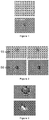
- Electron microscopy analysis of high-index enamel substrates with high bismuth enamel showed that these surface irregularities were tiny craters due to the presence of air bubbles. frozen during bursting on the surface of the enamel layer during the formation thereof by melting a glass frit (see Figure 1 ). These tiny craters are small in number and so small that leakage currents, generated in OLEDs made on such substrates, should remain within acceptable limits. It was therefore assumed that these craters were considerably dug and enlarged during etching because of the poor acid resistance of enamels with high bismuth content.
- barrier layers known to resist acids, such as layers of TiO 2 , SnO 2 , SiO 2 , Si 3 N 4 or silicon oxynitride (SiON) in thicknesses ranging from 20 to 150
- SiON silicon oxynitride
- the figure 3 shows the surface defects observed after acid etching of a metal layer deposited by magnetron sputtering on an ITO anode (thickness of about 150 ⁇ m), itself deposited by magnetron sputtering on a SiON barrier layer of a 100 nm thick.
- US2014 / 0048790 discloses an OLED device comprising a diffusing layer formed from a high index enamel and a stack of two barrier layers, for example TiO 2 / TiZr x O y, between the diffusing layer and the first electrode.
- US2014 / 0042415 describes an OLED device comprising a high index diffusing layer covered with a monolayer barrier layer that can be deposited by ALD.
- WO2013 / 187735 describes an OLED device comprising a diffusing layer formed of a high-index enamel coated with a barrier layer comprising SiO 2 or Si 3 N 4 or an alternation of these two layers.
- the present invention is based on the discovery that small defects (craters, Figure 1 ) on the surface of enamel layers with a high bismuth content can be effectively protected against the damage caused by acid etching, by means of a very thin layer of certain metal oxides, provided that this layer is formed by deposition of atomic layers (ALD, atomic layer deposition ).
- This thin protective layer must be located between the enamel diffusing layer (IEL), on the one hand, and the metal grid of the anode, on the other hand. It will be formed under the anode consisting of the TCO and the metal grid, preferably directly on the enamel layer.
- IEL enamel diffusing layer
- the present invention therefore relates to a transparent electrode as described in claim 1.
- the transparent electrode as defined above does not necessarily yet comprise a metal grid.
- the TCO anode will be subsequently structured by etching and provided with a metal gate by the OLED manufacturer.
- the protective layer deposited by ALD will effectively protect the enamel rich in bismuth against acid erosion and will prevent the formation of black spots in the final OLED.
- the present invention of course also relates to a complete transparent supported electrode which comprises, in addition to layers (i) to (iv) above, a metal gate for increasing the conductivity of the electrode.
- This metal grid may be located under or on the TCO layer and must be in direct electrical contact with it.
- the mineral glass substrate may be of any thickness compatible with the intended use. Leaves are conventionally used of glass having a thickness of between 0.3 and 5 mm, in particular between 0.7 and 3 mm. However, the use of ultrathin glass sheets having smaller thicknesses, typically between 50 nm and 300 nm is also possible, provided to solve the mechanical problems involved in the formation of an enamel layer, in which high index enamel, on such thin glasses.
- the substrate is surmounted by a diffusing layer formed of a high-index enamel containing at least 30% by weight of Bi 2 O 3 .
- the diffusing layer (ii) acts as an Internal Extraction Layer ( IEL).
- the high-index enamel forming the diffusing layer thus contains light scattering elements dispersed in the thickness of the layer.
- These diffusing elements have a refractive index higher or lower than the index of enamel. To diffuse the light, these elements must have significant dimensions relative to the wavelength of the light to be extracted, for example a size between 0.1 and 5 microns, preferably between 0.4 and 3 microns.
- the diffusing elements may be, for example, solid particles added to the glass frit before melting, crystals formed during the melting of the frit or air bubbles formed during the melting step of the frit and trapped in the frit. solidified enamel.
- the roughness of the interface between the high index enamel (n ⁇ 1.7) and the underlying lower index medium (glass substrate or low index layer formed on the surface of the glass) is at the origin of the phenomenon of diffusion.
- the interface between the high-index enamel and the underlying lower-index medium (substrate) preferably has a roughness profile with an arithmetic average deviation R a of at least 0.1 ⁇ m, preferably between 0. , 2 and 5 ⁇ m, in particular between 0.3 and 3 ⁇ m.
- an intermediate layer with a low refractive index (n ⁇ 1.6) is provided between the glass substrate and the enamel, for example a barrier layer protecting the high enamel index against the diffusion of alkaline ions coming from the substrate, it is the interface between this low index layer and the high index enamel which constitutes the relief having this roughness profile.
- diffusing layer for example by introducing diffusing elements, such as air bubbles, into a high-index enamel deposited on a surface of rough glass, the essential point being that the upper face of the IEL coincides with the upper face of the enamel high index.
- the present invention is particularly focused on enamels with high bismuth content which have a relatively low chemical resistance to acids, causing leakage currents and black spots as explained in the introduction.
- the high-index enamels of the present invention contain at least 30% by weight, preferably at least 50% by weight and in particular at least 65% by weight of Bi 2 O 3 .
- These enamels are known and described for example in the international application WO2013 / 187736 and WO2014 / 128421 and FR3002533 .
- the high-index enamel contains, for example, from 55 to 84% by weight of Bi 2 O 3 , up to approximately 20% by weight of BaO, from 5 to 20% by weight of ZnO, from 1 to 7% by weight.
- Al 2 O 3 5 to 15% by weight of SiO 2 , 5 to 20% by weight of B 2 O 3 and up to 0.3% by weight of CeO 2 .
- a layer of dielectric metal oxide (layer (iii)) is deposited by ALD (atomic layer deposition ) on the enamel high index described above. This deposit is preferably directly on the surface of the enamel high index.
- ALD atomic layer deposition
- Atomic layer deposition is a well-known method for the formation of extremely thin, uniform and tight layers.
- a gaseous precursor brought into contact with a surface, adsorbs in the form of a monolayer by chemisorption or physisorption.
- a second gaseous component capable of reacting with the adsorbed precursor is admitted into the chamber.
- the chamber is again purged and the cycle "adsorption - purge - reaction - purge" can start again.
- the following table shows some examples of precursors and reagents for the formation of the dielectric metal oxides of the layer (iii) of the present invention.
- Dielectric metal oxide Gaseous precursor Gaseous reagent Al 2 O 3 Al (CH 3 ) 3 H 2 O ZrO 2 Tetrakis (ethylmethylamino) zirconium Zr [(N (CH 3 ) (C 2 H 5 )] 4 H 2 O TiO 2 Tetrakis (dimethylamino) titanium Ti [N (CH 3 ) 2 ] 4 H 2 O
- ALD Atomic layer deposition
- the barrier layer is a complex layer formed of several successive sub-layers of different metal oxides, all deposited by ALD.
- the barrier layer ALD comprises several layers of Al 2 O 3 (n ⁇ 1.7) alternating with higher index oxide layers (n> 2) chosen from TiO 2 , ZrO 2 , and HfO 2 .
- Aluminum oxide has the advantage of being very resistant to strong acids used for the etching of metals, such as aqua regia . Its relatively low refractive index compared to that of OLED organic layers and the resulting optical loss, however, preclude the use of thick Al 2 O 3 monolayers.
- By alternating layers of Al 2 O 3 with layers of TiO 2 , ZrO 2 or HfO 2 it is possible to increase the overall thickness of the ALD layer without increasing the optical losses.
- the overall thickness of the ALD layer is preferably between 5 and 200 nm, in particular between 10 and 100 nm.
- the thickness of each sub-layers is preferably between 1 and 50 nm, in particular between 2 and 10 nm.
- the number of sub-layers can be between 2 and 200, preferably between 3 and 100, in particular between 5 and 10.
- the number of Al 2 O 3 layers is preferably between 2 and 5, it is in particular equal to at 2 or 3.
- the two outer layers of the underlayment stack are Al 2 O 3 layers which provide good contact with adjacent materials.
- a layer of a dielectric metal oxide deposited by ALD can be readily differentiated from a cathodically deposited layer. It is distinguished, in a known manner, by an extremely uniform thickness, a perfect continuity, even for small thicknesses, and a high conformity to the relief of the underlying substrate, even on surfaces with very pronounced relief.
- the transparent electrode itself.
- This electrode consists of a layer of a TCO, generally deposited by cathodic sputtering, and a metal gate, these two structures being in contact with one another.
- the metal grid may be under the TCO layer - between the TCO layer and the ALD layer - or on the TCO layer.
- the present invention is not particularly limited to certain grid structures or dimensions.
- the nature of the metal forming the gate is not decisive either. It is however essential that the grid is formed according to a method comprising a step of acid etching a metal layer, typically through a mask. As explained in the introduction, the Applicant has indeed found that it is this etching step that seems to be at the origin of the defects observed in the finished product (leakage currents, black dots). Methods of forming such grids by photolithography and acid etching are known.
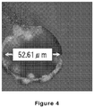
- the Applicant has observed, rarely, black dots giving rise to leakage currents, even when the OLED has no metal grid. An electron microscopic examination of the appearance of these blackheads has shown that they also clearly correspond to craters dug (see Figure 4 ). The Applicant assumes that the chemical etching of these surface defects occurs at the time of acidic etching of the TCO layer in areas where the surface relief is too pronounced to be adequately protected by a thin layer of photoresist ( 1 to 2 ⁇ m). The use of a barrier layer deposited by ALD between the enamel of the IEL layer and the TCO effectively manages to prevent this type of black spots.
- the TCO layer is deposited on the high index enamel protected by the dielectric metal oxide layer, by conventional deposition methods such as magnetron sputtering, sol-gel processes or pyrolysis (CVD).
- this electrode layer any transparent or translucent conducting oxide having a sufficiently high refractive index, close to the average index of the organic stack of an OLED (HTL / EL / ITL).
- transparent conductive oxides such as aluminum-doped zinc oxide (AZO), indium-doped tin oxide (ITO), aluminum oxide, and aluminum oxide. tin and zinc (SnZnO) or tin dioxide (SnO 2 ).
- AZO aluminum-doped zinc oxide
- ITO indium-doped tin oxide
- SnZnO tin and zinc
- SnO 2 tin dioxide
- These materials advantageously have a much lower absorption coefficient than the organic materials forming the stack HTL / EL / ITL, preferably an absorption coefficient of less than 0.005, in particular less than 0.0005. It is preferable to use ITO.
- the thickness of the transparent conductive oxide layer is typically between 50 and 200 nm.
- the process according to the invention comprises only these three steps, it results in an intermediate product (substrate-enamel high index-layer ALD-TCO layer) intended to receive later the metal grid.
- the method for producing a complete supported transparent electrode according to the invention will of course also comprise an additional step (step (d)) of forming a metal gate directly in contact with the transparent conductive oxide layer, this step (d) having at least one acid etching step.
- This etching step is carried out on a continuous metal layer covered by a mask created for example by screen printing or photolithography, the acid serving to remove the metal in certain areas not covered by the mask, so as to form the openings of the grid.
- the thickness of the metal layer, and therefore the height of the resulting grid is of the order of several hundred nanometers, typically from 0.5 to 1 ⁇ m, preferably from 0.6 to 0.8 ⁇ m.
- the width of the strands of the gate is generally between 10 microns and about 100 microns.
- step (d) is carried out after step (c) so that the metal gate is in contact with the TCO layer but not with the metal oxide barrier layer.
- step (d) is carried out after step (b) and before step (c) so that the metal gate or in contact with both the dielectric metal oxide barrier layer and the TCO layer.
- the metal grid is always a relief, because even when the TCO layer is deposited on the metal grid, as in this second embodiment, it is obvious, given the respective thicknesses of these two structures (0.05 to 0, 2 ⁇ m for the TCO layer, 0.5 to 1 ⁇ m for the grid), that the TCO layer can not cover and flatten this relief.
- the metal gate must be covered with a passivation layer which leaves, of course, free the etched openings, which constitute the illuminated areas of the final OLED.
- a passivation layer which leaves, of course, free the etched openings, which constitute the illuminated areas of the final OLED.
- the covering of the electrode grids by a passivation layer is also part of the general knowledge of those skilled in the art of manufacturing OLEDs.
- the substrate for OLED is advantageously covered, in a known manner, with an organic hole-injection material such as PEDOT / PSS (polyethylenedioxythiophene / poly (styrene sulphonate)) which makes it possible to planarize the relief of the substrate described above.
- PEDOT / PSS polyethylenedioxythiophene / poly (styrene sulphonate)
- a layer of a high enamel index is deposited on a sheet of 0.7 mm thick mineral glass by melting a glass frit having the following composition (% by weight): 65% of Bi 2 O 3 , 12.6% ZnO, 12.9% SiO 2 , 2.6% Al 2 O 3 , and 6.9% B 2 O 3 .
- a glass frit paste in an organic medium (75% by weight of frit, 22% by weight of volatile organic solvent and 3% of ethylcellulose) is deposited by screen printing, dried (about 20 minutes at 130 ° C.), The ethylcellulose is removed by a heat treatment of 20 minutes at 430 ° C and the frit is then raised to 540 ° C for 10 minutes. This fusion is carried out at atmospheric pressure which results in the formation of numerous air bubbles in the enamel layer.
- the enamel layer high index thus formed has surface defects due to frozen air bubbles during bursting.
- the figure 1 shows two images of scanning electron microscopy (SEM) of a partially open bubble ( bubble partially open ) and totally overte ( open bubble ) on the surface of the enamel.
- SEM scanning electron microscopy
- FIG. 2 shows, on the left, SEM images of two surface defects (frozen air bubbles during bursting) identified on these enamels protected by the ALD layer.
- the figure 2 shows, on the right, the SEM images of the same surface defects after the etching step. We note that their appearance is strictly identical to that before engraving.
- the figure 3 shows two SEM images of surface defects observed after acid etching (a solution of phosphoric acid at pH ⁇ 1, 100 seconds at a temperature of 45 ° C) of a metal layer deposited on an ITO anode (thickness of approximately 150 ⁇ m), itself deposited on a SiON barrier layer with a thickness of 100 nm on an enamel of the composition indicated above, the ITO anode and the barrier layer being deposited by magnetron sputtering.
Description
La présente invention concerne une électrode supportée destinée à être utilisée, de préférence en tant qu'anode, dans une diode électroluminescente organique.The present invention relates to a supported electrode for use, preferably as anode, in an organic light-emitting diode.
Une diode électroluminescente organique (OLED, de l'anglais Organic Light Emitting Diode) est un dispositif opto-électronique comportant deux électrodes dont une au moins est transparente à la lumière visible, et un empilement de couches minces comportant au moins une couche émettrice de lumière (couche EL). Cette couche émettrice de lumière est prise en sandwich au moins entre, d'une part, une couche d'injection ou de transport d'électrons (EIL ou ETL) située entre la couche EL et la cathode et, d'autre part, une couche d'injection ou de transport de trous (HIL ou HTL) située entre la couche EL et l'anode.An organic light emitting diode (OLED, English Organic Light Emitting Diode) is an optoelectronic device having two electrodes of which at least one is transparent to visible light, and a stack of thin layers comprising at least a light emitting layer (EL layer). This light-emitting layer is sandwiched at least between, on the one hand, an electron injection or transport layer (EIL or ETL) located between the EL layer and the cathode and, on the other hand, a injection or hole transport layer (HIL or HTL) located between the EL layer and the anode.
Les OLED comportant un support d'électrode transparent et une électrode transparente en contact avec celui-ci sont classiquement appelées OLED à émission à travers le substrat ou OLED à émission vers le bas (bottom emitting OLED). L'électrode transparente est dans ce cas typiquement l'anode.OLEDs having a transparent electrode support and a transparent electrode in contact therewith are conventionally referred to as OLEDs that emit through the substrate or OLEDs that emit downward ( bottom emitting OLED ). In this case, the transparent electrode is typically the anode.
De façon analogue, les OLED comportant un support d'électrode opaque sont appelées OLED à émission vers le haut (top emitting OLED), l'émission se faisant alors à travers l'électrode transparente qui n'est pas en contact avec le support, généralement la cathode.Similarly, OLEDs with an opaque electrode support are called OLEDs ( top emitting OLED ), the emission then being through the transparent electrode which is not in contact with the support, usually the cathode.
Au-delà d'un seuil de potentiel donné, la puissance lumineuse d'une OLED dépend directement de la différence de potentiel entre l'anode et la cathode. Pour fabriquer des OLED de grande taille présentant une puissance lumineuse homogène sur toute leur surface, il est nécessaire de limiter le plus possible la chute ohmique entre les arrivées de courant, généralement situées en bordure des OLED, et le centre de l'OLED. Une voie connue pour limiter cette chute ohmique est la réduction de la résistance par carré (R□ ou Rs, de l'anglais sheet resistance) des électrodes, typiquement par augmentation de leur épaisseur.Beyond a given threshold of potential, the luminous power of an OLED depends directly on the potential difference between the anode and the cathode. To make large OLEDs with homogeneous light power over their entire surface, it is necessary to minimize the ohmic drop between current arrivals, usually located at the edges of OLEDs, and the center of the OLED. A known way to limit this ohmic drop is the reduction of the resistance by square (R □ or R s , of English sheet resistance ) of the electrodes, typically by increasing their thickness.
Une telle augmentation de l'épaisseur des électrodes pose toutefois d'importants problèmes lorsqu'il s'agit d'électrodes transparentes. En effet, les matériaux utilisés pour ces électrodes, par exemple l'ITO (Indium Tin Oxide), présentent une transmission lumineuse insuffisante et un coût prohibitif qui font que des épaisseurs supérieures à 500 nm sont très peu intéressantes. En pratique, les couches d'ITO ne dépassent pas environ 150 nm.Such an increase in the thickness of the electrodes, however, poses significant problems when it comes to transparent electrodes. Indeed, the materials used for these electrodes, for example ITO (Indium Tin Oxide), have insufficient light transmission and a prohibitive cost that make thicknesses greater than 500 nm are very uninteresting. In practice, the ITO layers do not exceed about 150 nm.
Il est bien connu de réduire ou surmonter ce problème de la conductivité insuffisante de l'ITO en doublant l'anode d'une grille métallique. Les grilles métalliques par exemple en cuivre ou, plus fréquemment, à triple couche Mo-Al-Mo ou Cr-Al-Cr (grilles MAM pour Métal-Aluminium-Métal) sont ainsi communément utilisées pour limiter la résistivité des anodes transparentes en ITO dans des dispositifs électro-optiques tels que des OLED (
La formation de telles grilles métalliques se fait généralement par dépôt de minces couches métalliques continues par pulvérisation cathodique, puis structuration (patterning) par photolithographie, comprenant une étape de gravure par un mélange approprié d'acides fort et faible, typiquement, H3PO4, HNO3 et CH3COOH, pour enlever le métal au niveau des ouvertures. Un mélange d'acides forts, tel que l'eau régale (HCl + HNO3) généralement utilisée pour la gravure de l'ITO, peut aussi être utilisé. Toutefois, lorsque la grille métallique est sur l'ITO, il est difficile de contrôler la gravure et d'empêcher l'endommagement de la surface de l'ITO.The formation of such metal grids is generally by deposition of thin continuous metal layers by sputtering, then patterning by photolithography, comprising an etching step with a suitable mixture of strong and weak acids, typically H 3 PO 4. , HNO 3 and CH 3 COOH, to remove the metal at the openings. A mixture of strong acids, such as aqua regia (HCl + HNO 3 ) generally used for the etching of the ITO, can also be used. However, when the metal grid is on the ITO, it is difficult to control etching and prevent damage to the ITO surface.
Lorsque la Demanderesse a mis en oeuvre de telles étapes de gravure à l'acide sur des substrats pour OLED portant des couches d'extraction internes (IEL, de l'anglais Internal Extraction Layer) à base d'émaux haut indice à forte teneur en bismuth, elle a eu la mauvaise surprise d'observer, dans le produit final, de forts courants de fuite et la formation progressive de points noirs (pinholes). De tels courants de fuite, qui constituent un problème assez répandu dans le domaine des OLED, sont dus à des court-circuits aux endroits où l'anode est localement trop proche de la cathode. Ils résultent généralement d'irrégularités de surface qui présentent un relief non négligeable par rapport à l'épaisseur de l'empilement de couches organiques (ETL/EL/HTL).When the Applicant has implemented such acid etching steps on substrates for OLED carrying internal extraction layers (IEL, of the English Internal Extraction Layer ) based on high-index enamels with high content. bismuth, she had the unpleasant surprise to observe, in the final product, strong leakage currents and the progressive formation of black spots ( pinholes ) . Such leakage currents, which are a fairly common problem in the field of OLEDs, are due to short circuits where the anode is locally too close to the cathode. They generally result from surface irregularities that negligible compared to the thickness of the stack of organic layers (ETL / EL / HTL).
L'analyse par microscopie électronique des substrats comportant des IEL à base d'émaux haut indice à forte teneur en bismuth a montré qu'à l'origine de ces irrégularités de surface étaient de minuscules cratères, dus à la présence de bulles d'air figées en cours d'éclatement à la surface de la couche d'émail lors de la formation de celle-ci par fusion d'une fritte de verre (voir
Ce qui était assez surprenant était le fait qu'on observait ce phénomène non seulement lorsqu'on gravait des couches métalliques directement en contact avec l'émail haut indice de la couche d'extraction interne (IEL) mais également lorsque la couche métallique était déposée au-dessus de la couche d'ITO (anode). Le même phénomène a aussi été observé, bien que plus rarement, lors de la gravure chimique de couches de TCO (sans grilles métalliques) et a été attribué à une protection insuffisante de la zone à fort relief (cratère) par le masque (photoresist). What was rather surprising was the fact that this phenomenon was observed not only when metal layers directly in contact with the enamel high index of the inner extraction layer (IEL) but also when the metal layer was deposited above the ITO layer (anode). The same phenomenon has also been observed, although more rarely, during the chemical etching of TCO layers (without metal grids) and has been attributed to insufficient protection of the area of high relief (crater) by the mask ( photoresist ) .
Le dépôt par pulvérisation cathodique de couches barrières, connues pour résister aux acides, telles que des couches de TiO2, SnO2, SiO2, Si3N4 ou d'oxynitrure de silicium (SiON) en des épaisseurs allant de 20 à 150 µm, entre l'IEL et l'anode n'a pas non plus permis de réduire de manière significative le phénomène des courants de fuite et points noirs dans les OLED fabriquées à partir de ces substrats.Sputtering deposition of barrier layers, known to resist acids, such as layers of TiO 2 , SnO 2 , SiO 2 , Si 3 N 4 or silicon oxynitride (SiON) in thicknesses ranging from 20 to 150 However, the difference between IEL and anode has not significantly reduced the phenomenon of leakage currents and black spots in OLEDs made from these substrates.
La
La présente invention est basée sur la découverte que les petits défauts (cratères,
Cette couche mince de protection doit être située entre la couche diffusante (IEL) en émail, d'une part, et la grille métallique de l'anode, d'autre part. Elle sera formée sous l'anode constituée du TCO et de la grille métallique, de préférence directement sur la couche d'émail.This thin protective layer must be located between the enamel diffusing layer (IEL), on the one hand, and the metal grid of the anode, on the other hand. It will be formed under the anode consisting of the TCO and the metal grid, preferably directly on the enamel layer.
La présente invention a donc pour objet une électrode transparente telle que décrite dans la revendication 1.The present invention therefore relates to a transparent electrode as described in claim 1.
Elle a également pour objet un procédé de fabrication d'une telle électrode transparente, comprenant le dépôt de la couche barrière par ALD, tel que décrit dans la revendication 7, et une OLED (organic light emitting diode) contenant une telle électrode transparente, telle que décrite dans la revendication 6.It also relates to a method of manufacturing such a transparent electrode, comprising the deposition of the barrier layer by ALD, as described in claim 7, and an OLED (organic light emitting diode) containing such a transparent electrode, such as as described in claim 6.
D'autres aspects de la présente invention sont décrits dans les revendications dépendantes.Other aspects of the present invention are described in the dependent claims.
On remarquera que l'électrode transparente telle que définie ci-dessus ne comporte pas encore forcément une grille métallique. La Demanderesse envisage en effet la mise sur le marché d'une électrode supportée telle que définie ci-dessus dont l'anode en TCO sera structurée ultérieurement par gravure et pourvue d'une grille métallique par le fabricant d'OLED. Lors de l'étape de gravure acide du TCO et lors de la formation de la grille métallique impliquant également une étape de gravure acide, la couche de protection déposée par ALD protégera efficacement l'émail riche en bismuth contre l'érosion par les acides et empêchera la formation de points noirs dans l'OLED finale.It will be noted that the transparent electrode as defined above does not necessarily yet comprise a metal grid. The Applicant is considering the placing on the market of a supported electrode as defined above, the TCO anode will be subsequently structured by etching and provided with a metal gate by the OLED manufacturer. During the step of acidic etching of the TCO and during the formation of the metal gate also involving an acidic etching step, the protective layer deposited by ALD will effectively protect the enamel rich in bismuth against acid erosion and will prevent the formation of black spots in the final OLED.
La présente invention concerne bien entendu également une électrode supportée transparente complète qui comporte, en plus des couches (i) à (iv) ci-dessus, une grille métallique destinée à augmenter la conductivité de l'électrode. Cette grille métallique peut être située sous ou sur la couche de TCO et doit être directement en contact électrique avec celle-ci.The present invention of course also relates to a complete transparent supported electrode which comprises, in addition to layers (i) to (iv) above, a metal gate for increasing the conductivity of the electrode. This metal grid may be located under or on the TCO layer and must be in direct electrical contact with it.
Dans un premier mode de réalisation l'électrode transparente de la présente invention, comprend donc, dans l'ordre,
- ∘ un substrat transparent en verre minéral,
- ∘ une couche diffusante formée d'un émail haut indice contenant au moins 30 % en poids de Bi2O3,
- ∘ une couche barrière comportant plusieurs couches d'Al2O3 en alternance avec des couches d'oxydes à plus haut indice (n>2) choisis parmi TiO2, ZrO2 et HfO2 déposée par ALD,
- ∘ une couche d'un oxyde conducteur transparent (TCO),
- ∘ une grille métallique directement en contact avec la couche de TCO.
- ∘ a transparent mineral glass substrate,
- A diffusing layer formed of a high-index enamel containing at least 30% by weight of Bi 2 O 3 ,
- A barrier layer comprising several layers of Al2O3 alternating with oxide layers with a higher index (n> 2) chosen from TiO 2 , ZrO 2 and HfO 2 deposited by ALD,
- A layer of a transparent conductive oxide (TCO),
- ∘ a metal grid directly in contact with the TCO layer.
Dans un deuxième mode de réalisation l'ordre des deux dernières couches est inversé par rapport au premier mode de réalisation et l'électrode transparente de la présente invention, comprend, successivement
- ∘ un substrat transparent en verre minéral,
- ∘ une couche diffusante formée d'un émail haut indice contenant au moins 30 % en poids de Bi2O3,
- ∘ une couche barrière comportant plusieurs couches d'Al2O3 en alternance avec des couches d'oxydes à plus haut indice (n>2) choisis parmi TiO2, ZrO2 et HfO2 déposée par ALD,
- ∘ une grille métallique directement en contact avec la couche de TCO.
- ∘ une couche d'un oxyde conducteur transparent (TCO).
- ∘ a transparent mineral glass substrate,
- A diffusing layer formed of a high-index enamel containing at least 30% by weight of Bi 2 O 3 ,
- A barrier layer comprising several layers of Al2O3 alternating with oxide layers with a higher index (n> 2) chosen from TiO 2 , ZrO 2 and HfO 2 deposited by ALD,
- ∘ a metal grid directly in contact with the TCO layer.
- ∘ a layer of transparent conductive oxide (TCO).
Le substrat en verre minéral peut avoir n'importe quelle épaisseur compatible avec l'utilisation envisagée. On utilisera classiquement des feuilles de verre ayant une épaisseur comprise entre 0,3 et 5 mm, en particulier entre 0,7 et 3 mm. Toutefois, l'utilisation de feuilles de verre ultramince ayant des épaisseurs plus faibles, typiquement comprises entre 50 nm et 300 nm est également envisageable, à condition de résoudre les problèmes mécaniques qu'implique la formation d'une couche d'émail, en l'occurrence l'émail à haut indice, sur des verres aussi minces.The mineral glass substrate may be of any thickness compatible with the intended use. Leaves are conventionally used of glass having a thickness of between 0.3 and 5 mm, in particular between 0.7 and 3 mm. However, the use of ultrathin glass sheets having smaller thicknesses, typically between 50 nm and 300 nm is also possible, provided to solve the mechanical problems involved in the formation of an enamel layer, in which high index enamel, on such thin glasses.
Le substrat est surmonté d'une couche diffusante formée d'un émail haut indice contenant au moins 30 % en poids de Bi2O3. On entend par émail « haut indice » ici un émail ayant un indice de réfraction (à λ = 550 nm) au moins égal à 1,7, de préférence compris entre 1,8 et 2,2.The substrate is surmounted by a diffusing layer formed of a high-index enamel containing at least 30% by weight of Bi 2 O 3 . By "high index" enamel is meant here an enamel having a refractive index (at λ = 550 nm) at least equal to 1.7, preferably between 1.8 and 2.2.
La couche diffusante (ii) joue le rôle de couche interne d'extraction de la lumière (en anglais Internal Extraction Layer, IEL).The diffusing layer (ii) acts as an Internal Extraction Layer ( IEL).
Il est connu depuis longtemps dans le domaine des OLED, qu'une petite fraction seulement de la lumière produite par la couche électroluminescente est émise vers l'extérieur, à travers l'anode transparente et le substrat en verre. En effet, comme l'indice optique du substrat en verre (nverre = 1,5) est inférieur à celui des couches organiques (n = 1,7 - 1,8) et de l'anode transparente (n = 1,9 à 2,1), la majeure fraction (environ 50 %) de la lumière se trouve piégée dans ces couches à haut indice comme dans un guide d'onde et est absorbée après un certain nombre de réflexions. Un phénomène analogue se produit à l'interface entre le verre du substrat (nverre = 1,5) et l'air (nair = 1,0) et piège environ 20 % de la lumière émise par la couche électroluminescente.It has long been known in the field of OLED that only a small fraction of the light produced by the electroluminescent layer is emitted outwardly through the transparent anode and the glass substrate. Indeed, since the optical index of the glass substrate (n glass = 1.5) is lower than that of the organic layers (n = 1.7 - 1.8) and the transparent anode (n = 1.9 at 2.1), the greater fraction (about 50%) of the light is trapped in these high-index layers as in a waveguide and is absorbed after a number of reflections. A similar phenomenon occurs at the interface between the substrate glass (n glass = 1.5) and the air (n air = 1.0) and traps about 20% of the light emitted by the electroluminescent layer.
Il est connu de réduire ce phénomène de piégeage de la lumière (réflexion totale interne) dans les couches à haut indice d'une OLED en insérant, entre le substrat en verre et l'anode transparente, un moyen d'extraction de la lumière, formé par exemple par un émail à haut indice contenant des particules diffusantes ou par une interface suffisamment rugueuse pour être diffusante, planarisée par une couche d'émail haut indice.It is known to reduce this light-trapping phenomenon (total internal reflection) in the high-index layers of an OLED by inserting, between the glass substrate and the transparent anode, a means for extracting light, formed for example by a high-index enamel containing scattering particles or an interface sufficiently rough to be diffusing, planarized by a layer of enamel high index.
L'expression « couche diffusante » englobe donc dans la présente invention
- une couche d'émail à haut indice de réfraction dans lequel sont dispersés des éléments diffusants, et
- une interface rugueuse entre deux milieux d'indices différents, typiquement la surface du verre présentant un certain relief de rugosité couvert par une couche d'émail haut indice.
- a high refractive index enamel layer in which scattering elements are dispersed, and
- a rough interface between two media of different indices, typically the surface of the glass having a certain roughness relief covered by a layer of enamel high index.
Dans un mode de réalisation, l'émail haut indice formant la couche diffusante contient donc des éléments diffusants la lumière, dispersés dans l'épaisseur de la couche. Ces éléments diffusants ont un indice de réfraction plus élevé ou plus faible que l'indice de l'émail. Pour diffuser la lumière, ces éléments doivent avoir des dimensions non négligeables par rapport à la longueur d'onde de la lumière à extraire, par exemple une taille comprise entre 0,1 et 5 µm, de préférence entre 0,4 et 3 µm. Les éléments diffusants peuvent être par exemple des particules solides ajoutées à la fritte de verre avant fusion, des cristaux formés lors de la fusion de la fritte ou encore des bulles d'air formées pendant l'étape de fusion de la fritte et piégées dans l'émail solidifié.In one embodiment, the high-index enamel forming the diffusing layer thus contains light scattering elements dispersed in the thickness of the layer. These diffusing elements have a refractive index higher or lower than the index of enamel. To diffuse the light, these elements must have significant dimensions relative to the wavelength of the light to be extracted, for example a size between 0.1 and 5 microns, preferably between 0.4 and 3 microns. The diffusing elements may be, for example, solid particles added to the glass frit before melting, crystals formed during the melting of the frit or air bubbles formed during the melting step of the frit and trapped in the frit. solidified enamel.
Dans un autre mode de réalisation, la rugosité de l'interface entre l'émail haut indice (n ≥ 1,7) et le milieu d'indice inférieur sous-jacent (substrat en verre ou couche de bas indice formée à la surface du verre) est à l'origine du phénomène de diffusion. L'interface entre l'émail haut indice et le milieu d'indice inférieur sous-jacent (substrat) présente de préférence un profil de rugosité avec un écart moyen arithmétique Ra au moins égal à 0,1 µm, de préférence compris entre 0,2 et 5 µm, en particulier entre 0,3 et 3 µm.In another embodiment, the roughness of the interface between the high index enamel (n ≥ 1.7) and the underlying lower index medium (glass substrate or low index layer formed on the surface of the glass) is at the origin of the phenomenon of diffusion. The interface between the high-index enamel and the underlying lower-index medium (substrate) preferably has a roughness profile with an arithmetic average deviation R a of at least 0.1 μm, preferably between 0. , 2 and 5 μm, in particular between 0.3 and 3 μm.
Dans l'éventualité où une couche intermédiaire à bas indice de réfraction (n<1,6) est prévue entre le substrat en verre et l'émail, par exemple une couche barrière protégeant l'émail haut indice contre la diffusion d'ions alcalins provenant du substrat, c'est l'interface entre cette couche bas indice et l'émail haut indice qui constitue le relief présentant ce profil de rugosité.In the event that an intermediate layer with a low refractive index (n <1.6) is provided between the glass substrate and the enamel, for example a barrier layer protecting the high enamel index against the diffusion of alkaline ions coming from the substrate, it is the interface between this low index layer and the high index enamel which constitutes the relief having this roughness profile.
Bien entendu il est possible de combiner ces deux modes de réalisation de la couche diffusante par exemple en introduisant des éléments diffusants, tels que des bulles d'air, dans un émail haut indice déposé sur une surface de verre rugueuse, le point essentiel étant que la face supérieure de l'IEL coïncide avec la face supérieure de l'émail haut indice.Of course it is possible to combine these two embodiments of the diffusing layer, for example by introducing diffusing elements, such as air bubbles, into a high-index enamel deposited on a surface of rough glass, the essential point being that the upper face of the IEL coincides with the upper face of the enamel high index.
Il existe un certain nombre de compositions de verre permettant d'obtenir des émaux à haut indice. La présente invention est particulièrement focalisée sur des émaux à teneur élevée en bismuth qui présentent une assez faible résistance chimique aux acides, à l'origine des courants de fuite et points noirs comme expliqué en introduction.There are a number of glass compositions for obtaining high-index enamels. The present invention is particularly focused on enamels with high bismuth content which have a relatively low chemical resistance to acids, causing leakage currents and black spots as explained in the introduction.
Les émaux haut indice de la présente invention contiennent au moins 30 % en poids, de préférence au moins 50 % en poids et en particulier au moins 65 % en poids de Bi2O3. Ces émaux sont connus et décrits par exemple dans la demande internationale
L'émail à haut indice contient par exemple de 55 à 84 % en poids de Bi2O3, jusqu'à environ 20 % en poids de BaO, de 5 à 20 % en poids de ZnO, de 1 à 7% en poids d'Al2O3, de 5 à 15 % en poids de SiO2, de 5 à 20 % en poids de B2O3 et jusqu'à 0,3 % en poids de CeO2.The high-index enamel contains, for example, from 55 to 84% by weight of Bi 2 O 3 , up to approximately 20% by weight of BaO, from 5 to 20% by weight of ZnO, from 1 to 7% by weight. Al 2 O 3 , 5 to 15% by weight of SiO 2 , 5 to 20% by weight of B 2 O 3 and up to 0.3% by weight of CeO 2 .
Dans la présente invention une couche d'oxyde métallique diélectrique (couche (iii)) est déposée par ALD (atomic layer deposition) sur l'émail haut indice décrit ci-avant. Ce dépôt se fait de préférence directement sur la surface de l'émail haut indice. Le dépôt de couches atomiques est une méthode bien connue permettant la formation de couches extrêmement minces, uniformes et étanches.In the present invention a layer of dielectric metal oxide (layer (iii)) is deposited by ALD ( atomic layer deposition ) on the enamel high index described above. This deposit is preferably directly on the surface of the enamel high index. Atomic layer deposition is a well-known method for the formation of extremely thin, uniform and tight layers.
Un précurseur gazeux, mis en contact avec une surface, s'y adsorbe sous forme de monocouche par chimisorption ou physisorption. Après purge du gaz précurseur, un deuxième composant gazeux, capable de réagir avec le précurseur adsorbé, est admis dans la chambre. Après réaction, la chambre est de nouveau purgée et le cycle « adsorption - purge - réaction - purge » peut recommencer.A gaseous precursor, brought into contact with a surface, adsorbs in the form of a monolayer by chemisorption or physisorption. After purging the precursor gas, a second gaseous component capable of reacting with the adsorbed precursor is admitted into the chamber. After reaction, the chamber is again purged and the cycle "adsorption - purge - reaction - purge" can start again.
Le tableau ci-après montre quelques exemples de précurseurs et réactifs permettant la formation des oxydes métalliques diélectriques de la couche (iii) de la présente invention
On pourra également se référer à des revues bibliographiques telles que l'article de
La couche barrière est une couche complexe formée de plusieurs sous-couches successives de différents oxydes métalliques, toutes déposées par ALD.The barrier layer is a complex layer formed of several successive sub-layers of different metal oxides, all deposited by ALD.
Selon présente invention, la couche barrière ALD comporte plusieurs couches d'Al2O3 (n ≈ 1,7) en alternance avec des couches d'oxyde à plus haut indice (n>2) choisis parmi TiO2, ZrO2, et HfO2. L'oxyde d'aluminium présente en effet l'avantage d'être très résistant aux acides forts utilisés pour la gravure des métaux, tels que l'eau régale (aqua regia). Son indice de réfraction relativement faible par rapport à celui des couches organiques de l'OLED et la perte optique qui en résulte interdisent toutefois l'utilisation de mono-couches d'Al2O3 épaisses. En alternant des couches d'Al2O3 avec des couches de TiO2, ZrO2 ou HfO2 il est possible d'augmenter l'épaisseur globale de la couche ALD sans augmenter les pertes optiques.According to the present invention, the barrier layer ALD comprises several layers of Al 2 O 3 (n ≈ 1.7) alternating with higher index oxide layers (n> 2) chosen from TiO 2 , ZrO 2 , and HfO 2 . Aluminum oxide has the advantage of being very resistant to strong acids used for the etching of metals, such as aqua regia . Its relatively low refractive index compared to that of OLED organic layers and the resulting optical loss, however, preclude the use of thick Al 2 O 3 monolayers. By alternating layers of Al 2 O 3 with layers of TiO 2 , ZrO 2 or HfO 2 it is possible to increase the overall thickness of the ALD layer without increasing the optical losses.
L'épaisseur globale de la couche ALD est de préférence comprise entre 5 et 200 nm, en particulier entre 10 et 100 nm. Lorsqu'il s'agit d'une couche complexe comportant une alternance de sous-couches d'Al2O3 et de sous-couches d'indice plus élevé telles que TiO2, ZrO2 et HfO2, l'épaisseur de chacune des sous-couches est de préférence comprise entre 1 et 50 nm, en particulier entre 2 et 10 nm. Le nombre de sous-couches peut être compris entre 2 et 200, de préférence entre 3 et 100, en particulier entre 5 et 10. Le nombre de couches Al2O3 est de préférence compris entre 2 et 5, il est en particulier égal à 2 ou 3.The overall thickness of the ALD layer is preferably between 5 and 200 nm, in particular between 10 and 100 nm. When it is a complex layer comprising an alternation of Al 2 O 3 sub-layers and higher index sub-layers such as TiO 2 , ZrO 2 and HfO 2 , the thickness of each sub-layers is preferably between 1 and 50 nm, in particular between 2 and 10 nm. The number of sub-layers can be between 2 and 200, preferably between 3 and 100, in particular between 5 and 10. The number of Al 2 O 3 layers is preferably between 2 and 5, it is in particular equal to at 2 or 3.
Dans un mode de réalisation préféré les deux couches externes de l'empilement de sous-couches sont des couches d'Al2O3 qui assurent un bon contact avec les matériaux adjacents.In a preferred embodiment the two outer layers of the underlayment stack are Al 2 O 3 layers which provide good contact with adjacent materials.
Au microscopique électronique une couche d'un oxyde métallique diélectrique déposée par ALD peut être aisément différenciée d'une couche déposée par pulvérisation cathodique. Elle se distingue, de manière connue, par une épaisseur extrêmement uniforme, une continuité parfaite, même pour de faibles épaisseurs, et par une grande conformité au relief du substrat sous-jacent, même sur des surfaces à relief très prononcé.By electron microscopy a layer of a dielectric metal oxide deposited by ALD can be readily differentiated from a cathodically deposited layer. It is distinguished, in a known manner, by an extremely uniform thickness, a perfect continuity, even for small thicknesses, and a high conformity to the relief of the underlying substrate, even on surfaces with very pronounced relief.
Au-dessus de la couche formée par ALD se trouve l'électrode transparente proprement dite. Cette électrode se compose d'une couche d'un TCO, généralement déposée par pulvérisation cathodique, et d'une grille métallique, ces deux structures étant en contact l'une avec l'autre. Comme déjà expliqué ci-dessus, la grille métallique peut être sous la couche de TCO - entre la couche de TCO et la couche ALD - ou sur la couche de TCO.Above the layer formed by ALD is the transparent electrode itself. This electrode consists of a layer of a TCO, generally deposited by cathodic sputtering, and a metal gate, these two structures being in contact with one another. As already explained above, the metal grid may be under the TCO layer - between the TCO layer and the ALD layer - or on the TCO layer.
La présente invention n'est pas particulièrement limitée à certaines structures ou dimensions de grilles. La nature du métal formant la grille n'est pas non plus déterminant. Il est toutefois essentiel que la grille soit formée selon un procédé comprenant une étape de gravure acide d'une couche métallique, typiquement à travers un masque. Comme expliqué en introduction, la Demanderesse a en effet constaté que c'est cette étape de gravure à l'acide qui semble être à l'origine des défauts observés dans le produit fini (courants de fuite, points noirs). Des procédés de formation de telles grilles par photolithographie et gravure acide sont connus.The present invention is not particularly limited to certain grid structures or dimensions. The nature of the metal forming the gate is not decisive either. It is however essential that the grid is formed according to a method comprising a step of acid etching a metal layer, typically through a mask. As explained in the introduction, the Applicant has indeed found that it is this etching step that seems to be at the origin of the defects observed in the finished product (leakage currents, black dots). Methods of forming such grids by photolithography and acid etching are known.
La Demanderesse a observé, rarement, des points noirs donnant lieu à des courants de fuite, même lorsque l'OLED ne comportait aucune grille métallique. Un examen au microscope électronique de l'aspect de ces points noirs a montré qu'ils correspondaient aussi de toute évidence à des cratères creusés (voir
La couche TCO est déposée sur l'émail haut indice protégé par la couche d'oxyde métallique diélectrique, par des procédés de dépôt usuels tels que la pulvérisation cathodique magnétron, les procédés sol-gel ou la pyrolyse (CVD).The TCO layer is deposited on the high index enamel protected by the dielectric metal oxide layer, by conventional deposition methods such as magnetron sputtering, sol-gel processes or pyrolysis (CVD).
On peut en principe utiliser pour cette couche d'électrode n'importe quel oxyde conducteur transparent ou translucide présentant un indice de réfraction suffisamment élevé, proche de l'indice moyen de l'empilement organique d'une OLED (HTL/EL/ITL). On peut citer à titre d'exemple de tels matériaux les oxydes conducteurs transparents tels que l'oxyde de zinc dopé à l'aluminium (AZO), l'oxyde d'étain dopé à l'indium (ITO), l'oxyde d'étain et de zinc (SnZnO) ou le dioxyde d'étain (SnO2). Ces matériaux ont avantageusement un coefficient d'absorption très inférieur à celui des matériaux organiques formant l'empilement HTL/EL/ITL, de préférence un coefficient d'absorption inférieur à 0,005, en particulier inférieur à 0,0005. On utilisera de préférence de l'ITO. L'épaisseur de la couche d'oxyde conducteur transparent est typiquement comprise entre 50 et 200 nm.It is possible in principle to use for this electrode layer any transparent or translucent conducting oxide having a sufficiently high refractive index, close to the average index of the organic stack of an OLED (HTL / EL / ITL). . Examples of such materials include transparent conductive oxides such as aluminum-doped zinc oxide (AZO), indium-doped tin oxide (ITO), aluminum oxide, and aluminum oxide. tin and zinc (SnZnO) or tin dioxide (SnO 2 ). These materials advantageously have a much lower absorption coefficient than the organic materials forming the stack HTL / EL / ITL, preferably an absorption coefficient of less than 0.005, in particular less than 0.0005. It is preferable to use ITO. The thickness of the transparent conductive oxide layer is typically between 50 and 200 nm.
Le procédé de fabrication d'une électrode supportée transparente pour OLED de la présente invention, comprend au moins les trois étapes successives suivantes
- (a) la mise à disposition d'un substrat transparent portant, sur une de ses faces, une couche diffusante formée d'un émail haut indice contenant au moins 30 % en poids de Bi2O3,
- (b) la formation par ALD, sur l'émail haut indice et directement en contact avec celui-ci, d'une couche comportant plusieurs couches d'Al2O3 en alternance avec des couches d'oxydes à plus haut indice (n>2) choisis parmi TiO2, ZrO2 et HfO2,
- (c) formation d'une couche de TCO sur la couche d'oxyde métallique diélectrique (b).
- (a) providing a transparent substrate carrying, on one of its faces, a diffusing layer formed of a high-index enamel containing at least 30% by weight of Bi 2 O 3 ,
- (b) the ALD formation, on the high index enamel and directly in contact therewith, of a layer having several Al 2 O 3 layers alternating with higher index oxide layers (n > 2) selected from TiO 2 , ZrO 2 and HfO 2 ,
- (c) forming a TCO layer on the dielectric metal oxide layer (b).
Lorsque le procédé selon l'invention comporte uniquement ces trois étapes, il aboutit à un produit intermédiaire (substrat-émail haut indice-couche ALD-couche TCO) destiné à recevoir ultérieurement la grille métallique.When the process according to the invention comprises only these three steps, it results in an intermediate product (substrate-enamel high index-layer ALD-TCO layer) intended to receive later the metal grid.
Le procédé de fabrication d'une électrode transparente supportée complète selon l'invention comprendra bien entendu en outre une étape additionnelle (étape (d)) de formation d'une grille métallique directement en contact avec la couche d'oxyde conducteur transparent, cette étape (d) comportant au moins une étape de gravure à l'acide.The method for producing a complete supported transparent electrode according to the invention will of course also comprise an additional step (step (d)) of forming a metal gate directly in contact with the transparent conductive oxide layer, this step (d) having at least one acid etching step.
Cette étape de gravure à l'acide est mise en oeuvre sur une couche métallique continue couverte par un masque créé par exemple par sérigraphie ou photolithographie, l'acide servant à éliminer le métal dans certaines zones non couvertes par le masque, de manière à former les ouvertures de la grille.This etching step is carried out on a continuous metal layer covered by a mask created for example by screen printing or photolithography, the acid serving to remove the metal in certain areas not covered by the mask, so as to form the openings of the grid.
L'épaisseur de la couche métallique, et donc la hauteur de la grille résultante, est de l'ordre de plusieurs centaines de nanomètres, typiquement de 0,5 à 1 µm, de préférence de 0,6 à 0,8 µm. La largeur des brins de la grille est généralement comprise entre 10 µm et environ 100 µm.The thickness of the metal layer, and therefore the height of the resulting grid, is of the order of several hundred nanometers, typically from 0.5 to 1 μm, preferably from 0.6 to 0.8 μm. The width of the strands of the gate is generally between 10 microns and about 100 microns.
Dans un premier mode de réalisation du procédé selon l'invention, l'étape (d) est mise en oeuvre après l'étape (c) de manière à ce que la grille métallique soit en contact avec la couche de TCO mais non pas avec la couche barrière d'oxyde métallique.In a first embodiment of the method according to the invention, step (d) is carried out after step (c) so that the metal gate is in contact with the TCO layer but not with the metal oxide barrier layer.
Dans un deuxième mode de réalisation, l'étape (d) est mise en oeuvre après l'étape (b) et avant l'étape (c) de manière à ce que la grille métallique soit en contact à la fois avec la couche barrière d'oxyde métallique diélectrique et avec la couche de TCO.In a second embodiment, step (d) is carried out after step (b) and before step (c) so that the metal gate or in contact with both the dielectric metal oxide barrier layer and the TCO layer.
La grille métallique constitue toujours un relief, car même lorsque la couche de TCO est déposée sur la grille métallique, comme dans ce deuxième mode de réalisation, il est évident, compte tenu des épaisseurs respectives de ces deux structures (0,05 à 0,2 µm pour la couche de TCO, 0,5 à 1 µm pour la grille), que la couche de TCO n'arrive pas à recouvrir et aplanir ce relief.The metal grid is always a relief, because even when the TCO layer is deposited on the metal grid, as in this second embodiment, it is obvious, given the respective thicknesses of these two structures (0.05 to 0, 2 μm for the TCO layer, 0.5 to 1 μm for the grid), that the TCO layer can not cover and flatten this relief.
Dans tous les cas, la grille métallique doit donc être couverte d'une couche de passivation qui laisse bien entendu libre les ouvertures gravées par l'acide, qui constituent les zones éclairées de l'OLED finale. Le recouvrement des grilles d'électrode par une couche de passivation fait également partie des connaissances générales de l'homme du métier spécialisé dans la fabrication d'OLED.In all cases, the metal gate must be covered with a passivation layer which leaves, of course, free the etched openings, which constitute the illuminated areas of the final OLED. The covering of the electrode grids by a passivation layer is also part of the general knowledge of those skilled in the art of manufacturing OLEDs.
Avant application des couches émettrices de lumière, le substrat pour OLED est avantageusement couvert de manière connue d'un matériau organique d'injection de trous tel que le PEDOT/PSS (polyéthylènedioxythiophène/poly(styrène sulfonate)) qui permet de planariser le relief du substrat décrit ci-dessus.Before application of the light-emitting layers, the substrate for OLED is advantageously covered, in a known manner, with an organic hole-injection material such as PEDOT / PSS (polyethylenedioxythiophene / poly (styrene sulphonate)) which makes it possible to planarize the relief of the substrate described above.
On dépose sur une feuille de verre minéral d'une épaisseur de 0,7 mm une couche d'un émail haut indice par fusion d'une fritte de verre ayant la composition suivante (% en poids) : 65 % de Bi2O3, 12,6 % de ZnO, 12,9 % de SiO2, 2,6 % de Al2O3, et 6,9 % de B2O3.A layer of a high enamel index is deposited on a sheet of 0.7 mm thick mineral glass by melting a glass frit having the following composition (% by weight): 65% of Bi 2 O 3 , 12.6% ZnO, 12.9% SiO 2 , 2.6% Al 2 O 3 , and 6.9% B 2 O 3 .
Une pâte de fritte de verre dans un milieu organique (75 % en poids de fritte, 22 % en poids de solvant organique volatil et 3 % d'éthylcellulose) est déposée par sérigraphie, séchée (environ 20 minutes à 130 °C), l'éthylcellulose est éliminée par un traitement thermique de 20 minutes à 430 °C, puis la fritte est portée à 540 °C pendant 10 minutes. Cette fusion est mise en oeuvre à pression atmosphérique ce qui se traduit par la formation de nombreuses bulles d'air dans la couche d'émail. La couche d'émail haut indice ainsi formée présente des défauts de surface dus à des bulles d'air figées en cours d'éclatement.A glass frit paste in an organic medium (75% by weight of frit, 22% by weight of volatile organic solvent and 3% of ethylcellulose) is deposited by screen printing, dried (about 20 minutes at 130 ° C.), The ethylcellulose is removed by a heat treatment of 20 minutes at 430 ° C and the frit is then raised to 540 ° C for 10 minutes. This fusion is carried out at atmospheric pressure which results in the formation of numerous air bubbles in the enamel layer. The enamel layer high index thus formed has surface defects due to frozen air bubbles during bursting.
La
On dépose ensuite sur deux échantillons de substrat portant l'émail haut indice une couche d'Al2O3 d'une épaisseur de 10 nm et 50 nm respectivement. La
On soumet ensuite ces mêmes substrats à une étape de gravure acide avec une solution d'acide phosphorique à pH < 1, 100 secondes à une température de 45 °C.These same substrates are then subjected to an acidic etching step with a solution of phosphoric acid at pH <1, 100 seconds at a temperature of 45 ° C.
La
A titre comparatif, la
Ces défauts (même agrandissement que la
Claims (10)
- Supported transparent electrode for an OLED, comprising, in succession:(i) a transparent substrate made of mineral glass;(ii) a scattering layer made of a high-index enamel having a refractive index of at least 1.7 (at λ = 550 nm) and containing at least 30% by weight Bi2O3;(iii) a barrier layer of at least one dielectric metal oxide selected from the group consisting of Al2O3, TiO2, ZrO2 and HfO2, deposited by atomic layer deposition (ALD); and(iv) a layer of a transparent conductive oxide (TCO),characterized in that the barrier layer deposited by ALD comprises a plurality of Al2O3 layers in alternation with layers of oxides of higher indices (n>2) selected from TiO2, ZrO2, and HfO2.
- Electrode according to Claim 1, further comprising a metal grid under or over the TCO layer and making direct contact therewith.
- Electrode according to any one of the preceding claims, wherein the thickness of the barrier layer deposited by ALD is comprised between 5 and 200 nm, preferably between 10 and 100 nm.
- Electrode according to any one of the preceding claims, wherein the high-index enamel forming the scattering layer contains elements that scatter light, dispersed throughout the thickness of the layer.
- Electrode according to any one of the preceding claims, wherein the interface between the high-index enamel and the underlying medium of lower index has a roughness profile with an arithmetic mean deviation Ra at least equal to 0.1 µm, preferably comprised between 0.2 and 5 µm and in particular between 0.3 and 3 µm.
- OLED comprising an electrode according to any one of the preceding claims.
- Process for manufacturing a supported transparent electrode for an OLED according to any one of the preceding claims, comprising the following successive steps:(a) providing a transparent substrate bearing, on one of its faces, a scattering layer formed from a high-index enamel containing at least 30% by weight Bi2O3;(b) forming by atomic layer deposition (ALD), on the high index enamel and in direct contact therewith, a barrier layer comprising a plurality of Al2O3 layers in alternation with layers of oxides of higher indices (n>2) selected from TiO2, ZrO2, and HfO2, and(c) forming a layer of a transparent conductive oxide (TCO) above the dielectric metal oxide layer (b).
- Process according to Claim 7, further comprising a step (d) of forming a metal grid making direct contact with the transparent conductive oxide layer, this step (d) comprising at least one step of acid etching.
- Process according to Claim 8, wherein step (d) is carried out after step (b) and before step (c) so that the metal grid makes contact both with the dielectric metal oxide barrier layer and with the TCO layer.
- Process according to Claim 8, wherein step (d) is carried out after step (c) so that the metal grid makes contact with the TCO layer but not with the metal oxide barrier layer.
Applications Claiming Priority (2)
| Application Number | Priority Date | Filing Date | Title |
|---|---|---|---|
| FR1453584A FR3020179B1 (en) | 2014-04-22 | 2014-04-22 | ELECTRODE SUPPORTED TRANSPARENT FOR OLED |
| PCT/FR2015/051069 WO2015162367A1 (en) | 2014-04-22 | 2015-04-20 | Transparent supported electrode for oled |
Publications (2)
| Publication Number | Publication Date |
|---|---|
| EP3134929A1 EP3134929A1 (en) | 2017-03-01 |
| EP3134929B1 true EP3134929B1 (en) | 2018-09-19 |
Family
ID=50976932
Family Applications (1)
| Application Number | Title | Priority Date | Filing Date |
|---|---|---|---|
| EP15723259.6A Not-in-force EP3134929B1 (en) | 2014-04-22 | 2015-04-20 | Transparent, supported electrode for oled |
Country Status (10)
| Country | Link |
|---|---|
| US (1) | US10319934B2 (en) |
| EP (1) | EP3134929B1 (en) |
| JP (1) | JP6684225B2 (en) |
| KR (1) | KR20160145596A (en) |
| CN (1) | CN106463641B (en) |
| ES (1) | ES2702210T3 (en) |
| FR (1) | FR3020179B1 (en) |
| RU (1) | RU2685086C2 (en) |
| TW (1) | TWI663761B (en) |
| WO (1) | WO2015162367A1 (en) |
Families Citing this family (3)
| Publication number | Priority date | Publication date | Assignee | Title |
|---|---|---|---|---|
| EP3082172A1 (en) | 2015-04-16 | 2016-10-19 | Saint-Gobain Glass France | Layered structure for an oled and a method for producing such a structure |
| CN112876078A (en) * | 2021-04-14 | 2021-06-01 | 亚细亚建筑材料股份有限公司 | High-transparency overglaze |
| US11527732B1 (en) * | 2022-05-31 | 2022-12-13 | Applied Materials, Inc. | OLED anode structures including amorphous transparent conducting oxides and OLED processing method comprising the same |
Family Cites Families (30)
| Publication number | Priority date | Publication date | Assignee | Title |
|---|---|---|---|---|
| FR1360522A (en) | 1962-06-15 | 1964-05-08 | Automotive Prod Co Ltd | Brake system operated by liquid pressure for vehicles |
| JP2000231985A (en) * | 1999-02-12 | 2000-08-22 | Denso Corp | Organic electroluminescence element |
| JP2002343562A (en) * | 2001-05-11 | 2002-11-29 | Pioneer Electronic Corp | Light-emitting display device and its manufacturing method |
| US20060154550A1 (en) | 2002-10-16 | 2006-07-13 | Nellissen Antonius J M | Method for manufacturing a light emitting display |
| WO2005053053A1 (en) | 2003-11-26 | 2005-06-09 | Koninklijke Philips Electronics N.V. | Light-emitting device comprising an etch-protective layer |
| US7508130B2 (en) * | 2005-11-18 | 2009-03-24 | Eastman Kodak Company | OLED device having improved light output |
| EP1916725A1 (en) | 2006-10-27 | 2008-04-30 | Nederlandse Organisatie voor toegepast-natuurwetenschappelijk Onderzoek TNO | Organic light emitting diode device with multilayer seal |
| EP2178343B2 (en) * | 2007-07-27 | 2020-04-08 | AGC Inc. | Translucent substrate, method for manufacturing the translucent substrate and organic led element |
| JPWO2009116531A1 (en) * | 2008-03-18 | 2011-07-21 | 旭硝子株式会社 | Electronic device substrate, laminate for organic LED element and method for producing the same, organic LED element and method for producing the same |
| DE102009024411A1 (en) * | 2009-03-24 | 2010-09-30 | Osram Opto Semiconductors Gmbh | Thin-film encapsulation for an optoelectronic component, method for its production and optoelectronic component |
| DE102009022900A1 (en) * | 2009-04-30 | 2010-11-18 | Osram Opto Semiconductors Gmbh | Optoelectronic component and method for its production |
| CN102574727B (en) * | 2009-10-15 | 2015-06-24 | 旭硝子株式会社 | Glass for diffusion layer in organic led element, and organic led element utilizing same |
| EA201270559A1 (en) * | 2009-10-15 | 2012-11-30 | Асахи Гласс Компани, Лимитед | ORGANIC LED ELEMENT, FRITTATED GLASS FOR SCATTERING LAYER FOR APPLICATION IN ORGANIC LED ELEMENT AND METHOD FOR OBTAINING DIFFUSION LAYER FOR APPLICATION IN ORGANIC LED ELEMENT |
| RU2408957C1 (en) * | 2009-11-25 | 2011-01-10 | Российская Федерация, от имени которой выступает государственный заказчик - Министерство промышленности и торговли Российской Федерации (Минпромторг России) | Organic light-emitting diode |
| FR2955575B1 (en) * | 2010-01-22 | 2012-02-24 | Saint Gobain | GLASS SUBSTRATE COATED WITH A HIGH INDEX LAYER UNDER AN ELECTRODE COATING AND ORGANIC ELECTROLUMINESCENT DEVICE COMPRISING SUCH A SUBSTRATE. |
| CN102845130B (en) * | 2010-04-08 | 2015-12-09 | 旭硝子株式会社 | The manufacture method of organic led element, light-transmitting substrate and organic led element |
| MX2013000609A (en) * | 2010-07-16 | 2013-07-03 | Agc Glass Europe | Transluscent conductive substrate for organic light emitting devices. |
| KR20130097144A (en) * | 2010-07-26 | 2013-09-02 | 아사히 가라스 가부시키가이샤 | Glass for scattering layer of organic led element, and organic led element |
| FR2963705B1 (en) * | 2010-08-06 | 2012-08-17 | Saint Gobain | DIFFUSING LAYER HOLDER FOR ORGANIC ELECTROLUMINESCENT DIODE DEVICE, ORGANIC ELECTROLUMINESCENT DEVICE COMPRISING SUCH A SUPPORT |
| JP5938757B2 (en) * | 2011-11-25 | 2016-06-22 | 三星電子株式会社Samsung Electronics Co.,Ltd. | LIGHT EMITTING ELEMENT BOARD AND ITS MANUFACTURING METHOD, SURFACE LIGHT EMITTING ELEMENT, LIGHTING APPARATUS, AND BACKLIGHT |
| JP5998124B2 (en) * | 2011-03-31 | 2016-09-28 | 旭硝子株式会社 | Organic LED element, translucent substrate, and manufacturing method of translucent substrate |
| WO2012147685A1 (en) * | 2011-04-28 | 2012-11-01 | 旭硝子株式会社 | Organic electroluminescence element, translucent substrate, and organic led element manufacturing method |
| EP2767518A4 (en) * | 2011-10-14 | 2016-01-06 | Asahi Glass Co Ltd | Glass for use in scattering layer of organic led element, multilayer substrate for use in organic led element and method for producing said multilayer substrate, and organic led element and method for producing same |
| WO2013062020A1 (en) * | 2011-10-28 | 2013-05-02 | 旭硝子株式会社 | Layered substrate for organic led element, and organic led element |
| FR2986909B1 (en) * | 2012-02-10 | 2014-11-21 | Saint Gobain | ELECTRODE SUPPORTED TRANSPARENT FOR OLED |
| KR20130111156A (en) * | 2012-03-30 | 2013-10-10 | 주식회사 엘지화학 | Substrate for organic electronic device |
| KR101715112B1 (en) | 2012-06-14 | 2017-03-10 | 쌩-고벵 글래스 프랑스 | Layered body for OLED, method for manufacturing the same and OLED element having the same |
| FR2993707B1 (en) * | 2012-07-17 | 2015-03-13 | Saint Gobain | ELECTRODE SUPPORTED TRANSPARENT FOR OLED |
| ES2548048T3 (en) * | 2012-09-28 | 2015-10-13 | Saint-Gobain Glass France | Method of producing a transparent diffuser OLED substrate |
| EP2958867A1 (en) | 2013-02-25 | 2015-12-30 | Saint-Gobain Glass France | Substrate for device having an organic light-emitting diode |
-
2014
- 2014-04-22 FR FR1453584A patent/FR3020179B1/en not_active Expired - Fee Related
-
2015
- 2015-03-31 TW TW104110455A patent/TWI663761B/en not_active IP Right Cessation
- 2015-04-20 KR KR1020167029067A patent/KR20160145596A/en not_active Application Discontinuation
- 2015-04-20 JP JP2016563841A patent/JP6684225B2/en not_active Expired - Fee Related
- 2015-04-20 US US15/305,529 patent/US10319934B2/en not_active Expired - Fee Related
- 2015-04-20 EP EP15723259.6A patent/EP3134929B1/en not_active Not-in-force
- 2015-04-20 ES ES15723259T patent/ES2702210T3/en active Active
- 2015-04-20 WO PCT/FR2015/051069 patent/WO2015162367A1/en active Application Filing
- 2015-04-20 CN CN201580018195.5A patent/CN106463641B/en not_active Expired - Fee Related
- 2015-04-20 RU RU2016145417A patent/RU2685086C2/en active
Non-Patent Citations (1)
| Title |
|---|
| None * |
Also Published As
| Publication number | Publication date |
|---|---|
| RU2016145417A3 (en) | 2018-11-19 |
| KR20160145596A (en) | 2016-12-20 |
| JP6684225B2 (en) | 2020-04-22 |
| EP3134929A1 (en) | 2017-03-01 |
| CN106463641B (en) | 2018-09-28 |
| US20170040565A1 (en) | 2017-02-09 |
| US10319934B2 (en) | 2019-06-11 |
| RU2685086C2 (en) | 2019-04-16 |
| TWI663761B (en) | 2019-06-21 |
| FR3020179A1 (en) | 2015-10-23 |
| JP2017514279A (en) | 2017-06-01 |
| CN106463641A (en) | 2017-02-22 |
| WO2015162367A1 (en) | 2015-10-29 |
| RU2016145417A (en) | 2018-05-23 |
| TW201605095A (en) | 2016-02-01 |
| ES2702210T3 (en) | 2019-02-27 |
| FR3020179B1 (en) | 2017-10-06 |
Similar Documents
| Publication | Publication Date | Title |
|---|---|---|
| BE1020735A3 (en) | VERTICAL TEXTURE SUBSTRATE WITH IMPROVED OPTICAL PROPERTIES FOR OPTOELECTRONIC DEVICE. | |
| FR2944147A1 (en) | METHOD FOR MANUFACTURING TEXTURED EXTERNAL SURFACE STRUCTURE FOR ORGANIC ELECTROLUMINESCENT DIODE DEVICE AND STRUTURE WITH TEXTURED EXTERNAL SURFACE | |
| EP2408268A1 (en) | Electrode for an organic light-emitting device, acid etching thereof, and organic light-emitting device incorporating it | |
| WO2010094775A1 (en) | Transparent substrate for photonic devices | |
| FR2944145A1 (en) | METHOD FOR MANUFACTURING TEXTURED SURFACE STRUCTURE FOR ORGANIC ELECTROLUMINESCENT DIODE DEVICE AND STRUCTURE WITH TEXTURED SURFACE | |
| EP2798682A1 (en) | Transparent anode for an oled | |
| EP3167497B1 (en) | Encapsulation of an organic optoelectronic component | |
| EP3134929B1 (en) | Transparent, supported electrode for oled | |
| EP3260511B1 (en) | Reversible bonding method between two elements | |
| WO2012028809A1 (en) | Support for organic-light-emitting-diode device, such an organic-light-emitting-diode device and process for manufacturing said device | |
| BE1019826A3 (en) | CONDUCTIVE TRANSPARENT GLASS SUBSTRATE FOR PHOTOVOLTAIC CELL. | |
| WO2013075879A1 (en) | Substrate with a functional layer comprising a sulphurous compound | |
| EP2883257A1 (en) | Diffusing conductive support for an oled device, and an oled device incorporating same | |
| EP2883258A1 (en) | Diffusing conductive support for an oled device, and an oled device incorporating same | |
| BE1019243A3 (en) | TRANSPARENT SUBSTRATE FOR PHOTONIC DEVICES. | |
| FR3129523A1 (en) | METHOD FOR MANUFACTURING AN OPTOELECTRONIC DEVICE | |
| FR2992098A1 (en) | Organic optoelectronic device for microdisplay, has protective inorganic dielectric film having metal oxide interposed between anode and radiation emitting structure of organic LED, where thickness of dielectric film is uniform | |
| FR2992475A1 (en) | Organic LED, has stack of thin organic layers including light emitting layer between electron transport layer and hole transport layer, and cathode including silver layer and aluminum layer deposited on silver layer |
Legal Events
| Date | Code | Title | Description |
|---|---|---|---|
| STAA | Information on the status of an ep patent application or granted ep patent |
Free format text: STATUS: THE INTERNATIONAL PUBLICATION HAS BEEN MADE |
|
| PUAI | Public reference made under article 153(3) epc to a published international application that has entered the european phase |
Free format text: ORIGINAL CODE: 0009012 |
|
| STAA | Information on the status of an ep patent application or granted ep patent |
Free format text: STATUS: REQUEST FOR EXAMINATION WAS MADE |
|
| 17P | Request for examination filed |
Effective date: 20161122 |
|
| AK | Designated contracting states |
Kind code of ref document: A1 Designated state(s): AL AT BE BG CH CY CZ DE DK EE ES FI FR GB GR HR HU IE IS IT LI LT LU LV MC MK MT NL NO PL PT RO RS SE SI SK SM TR |
|
| AX | Request for extension of the european patent |
Extension state: BA ME |
|
| DAV | Request for validation of the european patent (deleted) | ||
| DAX | Request for extension of the european patent (deleted) | ||
| GRAP | Despatch of communication of intention to grant a patent |
Free format text: ORIGINAL CODE: EPIDOSNIGR1 |
|
| STAA | Information on the status of an ep patent application or granted ep patent |
Free format text: STATUS: GRANT OF PATENT IS INTENDED |
|
| INTG | Intention to grant announced |
Effective date: 20180329 |
|
| GRAS | Grant fee paid |
Free format text: ORIGINAL CODE: EPIDOSNIGR3 |
|
| GRAA | (expected) grant |
Free format text: ORIGINAL CODE: 0009210 |
|
| STAA | Information on the status of an ep patent application or granted ep patent |
Free format text: STATUS: THE PATENT HAS BEEN GRANTED |
|
| AK | Designated contracting states |
Kind code of ref document: B1 Designated state(s): AL AT BE BG CH CY CZ DE DK EE ES FI FR GB GR HR HU IE IS IT LI LT LU LV MC MK MT NL NO PL PT RO RS SE SI SK SM TR |
|
| REG | Reference to a national code |
Ref country code: GB Ref legal event code: FG4D Free format text: NOT ENGLISH |
|
| REG | Reference to a national code |
Ref country code: CH Ref legal event code: EP |
|
| REG | Reference to a national code |
Ref country code: AT Ref legal event code: REF Ref document number: 1044271 Country of ref document: AT Kind code of ref document: T Effective date: 20181015 |
|
| REG | Reference to a national code |
Ref country code: IE Ref legal event code: FG4D Free format text: LANGUAGE OF EP DOCUMENT: FRENCH |
|
| REG | Reference to a national code |
Ref country code: DE Ref legal event code: R096 Ref document number: 602015016627 Country of ref document: DE |
|
| REG | Reference to a national code |
Ref country code: CH Ref legal event code: NV Representative=s name: DENNEMEYER AG, CH |
|
| REG | Reference to a national code |
Ref country code: NL Ref legal event code: FP |
|
| PG25 | Lapsed in a contracting state [announced via postgrant information from national office to epo] |
Ref country code: GR Free format text: LAPSE BECAUSE OF FAILURE TO SUBMIT A TRANSLATION OF THE DESCRIPTION OR TO PAY THE FEE WITHIN THE PRESCRIBED TIME-LIMIT Effective date: 20181220 Ref country code: FI Free format text: LAPSE BECAUSE OF FAILURE TO SUBMIT A TRANSLATION OF THE DESCRIPTION OR TO PAY THE FEE WITHIN THE PRESCRIBED TIME-LIMIT Effective date: 20180919 Ref country code: BG Free format text: LAPSE BECAUSE OF FAILURE TO SUBMIT A TRANSLATION OF THE DESCRIPTION OR TO PAY THE FEE WITHIN THE PRESCRIBED TIME-LIMIT Effective date: 20181219 Ref country code: LT Free format text: LAPSE BECAUSE OF FAILURE TO SUBMIT A TRANSLATION OF THE DESCRIPTION OR TO PAY THE FEE WITHIN THE PRESCRIBED TIME-LIMIT Effective date: 20180919 Ref country code: NO Free format text: LAPSE BECAUSE OF FAILURE TO SUBMIT A TRANSLATION OF THE DESCRIPTION OR TO PAY THE FEE WITHIN THE PRESCRIBED TIME-LIMIT Effective date: 20181219 Ref country code: SE Free format text: LAPSE BECAUSE OF FAILURE TO SUBMIT A TRANSLATION OF THE DESCRIPTION OR TO PAY THE FEE WITHIN THE PRESCRIBED TIME-LIMIT Effective date: 20180919 Ref country code: RS Free format text: LAPSE BECAUSE OF FAILURE TO SUBMIT A TRANSLATION OF THE DESCRIPTION OR TO PAY THE FEE WITHIN THE PRESCRIBED TIME-LIMIT Effective date: 20180919 |
|
| REG | Reference to a national code |
Ref country code: LT Ref legal event code: MG4D |
|
| REG | Reference to a national code |
Ref country code: ES Ref legal event code: FG2A Ref document number: 2702210 Country of ref document: ES Kind code of ref document: T3 Effective date: 20190227 |
|
| PG25 | Lapsed in a contracting state [announced via postgrant information from national office to epo] |
Ref country code: AL Free format text: LAPSE BECAUSE OF FAILURE TO SUBMIT A TRANSLATION OF THE DESCRIPTION OR TO PAY THE FEE WITHIN THE PRESCRIBED TIME-LIMIT Effective date: 20180919 Ref country code: HR Free format text: LAPSE BECAUSE OF FAILURE TO SUBMIT A TRANSLATION OF THE DESCRIPTION OR TO PAY THE FEE WITHIN THE PRESCRIBED TIME-LIMIT Effective date: 20180919 Ref country code: LV Free format text: LAPSE BECAUSE OF FAILURE TO SUBMIT A TRANSLATION OF THE DESCRIPTION OR TO PAY THE FEE WITHIN THE PRESCRIBED TIME-LIMIT Effective date: 20180919 |
|
| PG25 | Lapsed in a contracting state [announced via postgrant information from national office to epo] |
Ref country code: CZ Free format text: LAPSE BECAUSE OF FAILURE TO SUBMIT A TRANSLATION OF THE DESCRIPTION OR TO PAY THE FEE WITHIN THE PRESCRIBED TIME-LIMIT Effective date: 20180919 Ref country code: PL Free format text: LAPSE BECAUSE OF FAILURE TO SUBMIT A TRANSLATION OF THE DESCRIPTION OR TO PAY THE FEE WITHIN THE PRESCRIBED TIME-LIMIT Effective date: 20180919 Ref country code: EE Free format text: LAPSE BECAUSE OF FAILURE TO SUBMIT A TRANSLATION OF THE DESCRIPTION OR TO PAY THE FEE WITHIN THE PRESCRIBED TIME-LIMIT Effective date: 20180919 Ref country code: IS Free format text: LAPSE BECAUSE OF FAILURE TO SUBMIT A TRANSLATION OF THE DESCRIPTION OR TO PAY THE FEE WITHIN THE PRESCRIBED TIME-LIMIT Effective date: 20190119 Ref country code: RO Free format text: LAPSE BECAUSE OF FAILURE TO SUBMIT A TRANSLATION OF THE DESCRIPTION OR TO PAY THE FEE WITHIN THE PRESCRIBED TIME-LIMIT Effective date: 20180919 |
|
| PG25 | Lapsed in a contracting state [announced via postgrant information from national office to epo] |
Ref country code: PT Free format text: LAPSE BECAUSE OF FAILURE TO SUBMIT A TRANSLATION OF THE DESCRIPTION OR TO PAY THE FEE WITHIN THE PRESCRIBED TIME-LIMIT Effective date: 20190119 Ref country code: SK Free format text: LAPSE BECAUSE OF FAILURE TO SUBMIT A TRANSLATION OF THE DESCRIPTION OR TO PAY THE FEE WITHIN THE PRESCRIBED TIME-LIMIT Effective date: 20180919 Ref country code: SM Free format text: LAPSE BECAUSE OF FAILURE TO SUBMIT A TRANSLATION OF THE DESCRIPTION OR TO PAY THE FEE WITHIN THE PRESCRIBED TIME-LIMIT Effective date: 20180919 |
|
| REG | Reference to a national code |
Ref country code: DE Ref legal event code: R097 Ref document number: 602015016627 Country of ref document: DE |
|
| PLBE | No opposition filed within time limit |
Free format text: ORIGINAL CODE: 0009261 |
|
| STAA | Information on the status of an ep patent application or granted ep patent |
Free format text: STATUS: NO OPPOSITION FILED WITHIN TIME LIMIT |
|
| PG25 | Lapsed in a contracting state [announced via postgrant information from national office to epo] |
Ref country code: DK Free format text: LAPSE BECAUSE OF FAILURE TO SUBMIT A TRANSLATION OF THE DESCRIPTION OR TO PAY THE FEE WITHIN THE PRESCRIBED TIME-LIMIT Effective date: 20180919 |
|
| 26N | No opposition filed |
Effective date: 20190620 |
|
| PG25 | Lapsed in a contracting state [announced via postgrant information from national office to epo] |
Ref country code: SI Free format text: LAPSE BECAUSE OF FAILURE TO SUBMIT A TRANSLATION OF THE DESCRIPTION OR TO PAY THE FEE WITHIN THE PRESCRIBED TIME-LIMIT Effective date: 20180919 |
|
| REG | Reference to a national code |
Ref country code: BE Ref legal event code: MM Effective date: 20190430 |
|
| PG25 | Lapsed in a contracting state [announced via postgrant information from national office to epo] |
Ref country code: MC Free format text: LAPSE BECAUSE OF FAILURE TO SUBMIT A TRANSLATION OF THE DESCRIPTION OR TO PAY THE FEE WITHIN THE PRESCRIBED TIME-LIMIT Effective date: 20180919 Ref country code: LU Free format text: LAPSE BECAUSE OF NON-PAYMENT OF DUE FEES Effective date: 20190420 |
|
| PG25 | Lapsed in a contracting state [announced via postgrant information from national office to epo] |
Ref country code: BE Free format text: LAPSE BECAUSE OF NON-PAYMENT OF DUE FEES Effective date: 20190430 |
|
| PG25 | Lapsed in a contracting state [announced via postgrant information from national office to epo] |
Ref country code: TR Free format text: LAPSE BECAUSE OF FAILURE TO SUBMIT A TRANSLATION OF THE DESCRIPTION OR TO PAY THE FEE WITHIN THE PRESCRIBED TIME-LIMIT Effective date: 20180919 |
|
| PG25 | Lapsed in a contracting state [announced via postgrant information from national office to epo] |
Ref country code: IE Free format text: LAPSE BECAUSE OF NON-PAYMENT OF DUE FEES Effective date: 20190420 |
|
| PGFP | Annual fee paid to national office [announced via postgrant information from national office to epo] |
Ref country code: CH Payment date: 20200420 Year of fee payment: 6 Ref country code: FR Payment date: 20200429 Year of fee payment: 6 Ref country code: ES Payment date: 20200504 Year of fee payment: 6 Ref country code: NL Payment date: 20200417 Year of fee payment: 6 Ref country code: DE Payment date: 20200408 Year of fee payment: 6 |
|
| PGFP | Annual fee paid to national office [announced via postgrant information from national office to epo] |
Ref country code: IT Payment date: 20200312 Year of fee payment: 6 Ref country code: GB Payment date: 20200408 Year of fee payment: 6 |
|
| PGFP | Annual fee paid to national office [announced via postgrant information from national office to epo] |
Ref country code: AT Payment date: 20200325 Year of fee payment: 6 |
|
| PG25 | Lapsed in a contracting state [announced via postgrant information from national office to epo] |
Ref country code: CY Free format text: LAPSE BECAUSE OF FAILURE TO SUBMIT A TRANSLATION OF THE DESCRIPTION OR TO PAY THE FEE WITHIN THE PRESCRIBED TIME-LIMIT Effective date: 20180919 |
|
| PG25 | Lapsed in a contracting state [announced via postgrant information from national office to epo] |
Ref country code: MT Free format text: LAPSE BECAUSE OF FAILURE TO SUBMIT A TRANSLATION OF THE DESCRIPTION OR TO PAY THE FEE WITHIN THE PRESCRIBED TIME-LIMIT Effective date: 20180919 Ref country code: HU Free format text: LAPSE BECAUSE OF FAILURE TO SUBMIT A TRANSLATION OF THE DESCRIPTION OR TO PAY THE FEE WITHIN THE PRESCRIBED TIME-LIMIT; INVALID AB INITIO Effective date: 20150420 |
|
| REG | Reference to a national code |
Ref country code: DE Ref legal event code: R119 Ref document number: 602015016627 Country of ref document: DE |
|
| REG | Reference to a national code |
Ref country code: NL Ref legal event code: MM Effective date: 20210501 |
|
| REG | Reference to a national code |
Ref country code: AT Ref legal event code: MM01 Ref document number: 1044271 Country of ref document: AT Kind code of ref document: T Effective date: 20210420 |
|
| GBPC | Gb: european patent ceased through non-payment of renewal fee |
Effective date: 20210420 |
|
| PG25 | Lapsed in a contracting state [announced via postgrant information from national office to epo] |
Ref country code: CH Free format text: LAPSE BECAUSE OF NON-PAYMENT OF DUE FEES Effective date: 20210430 Ref country code: AT Free format text: LAPSE BECAUSE OF NON-PAYMENT OF DUE FEES Effective date: 20210420 Ref country code: LI Free format text: LAPSE BECAUSE OF NON-PAYMENT OF DUE FEES Effective date: 20210430 Ref country code: GB Free format text: LAPSE BECAUSE OF NON-PAYMENT OF DUE FEES Effective date: 20210420 Ref country code: FR Free format text: LAPSE BECAUSE OF NON-PAYMENT OF DUE FEES Effective date: 20210430 Ref country code: DE Free format text: LAPSE BECAUSE OF NON-PAYMENT OF DUE FEES Effective date: 20211103 |
|
| REG | Reference to a national code |
Ref country code: AT Ref legal event code: UEP Ref document number: 1044271 Country of ref document: AT Kind code of ref document: T Effective date: 20180919 |
|
| PG25 | Lapsed in a contracting state [announced via postgrant information from national office to epo] |
Ref country code: NL Free format text: LAPSE BECAUSE OF NON-PAYMENT OF DUE FEES Effective date: 20210501 |
|
| PG25 | Lapsed in a contracting state [announced via postgrant information from national office to epo] |
Ref country code: MK Free format text: LAPSE BECAUSE OF FAILURE TO SUBMIT A TRANSLATION OF THE DESCRIPTION OR TO PAY THE FEE WITHIN THE PRESCRIBED TIME-LIMIT Effective date: 20180919 |
|
| REG | Reference to a national code |
Ref country code: ES Ref legal event code: FD2A Effective date: 20220704 |
|
| PG25 | Lapsed in a contracting state [announced via postgrant information from national office to epo] |
Ref country code: ES Free format text: LAPSE BECAUSE OF NON-PAYMENT OF DUE FEES Effective date: 20210421 |
|
| PG25 | Lapsed in a contracting state [announced via postgrant information from national office to epo] |
Ref country code: IT Free format text: LAPSE BECAUSE OF NON-PAYMENT OF DUE FEES Effective date: 20200420 |