EP3134579B1 - Method and system for anchoring a waterproofing liner to concrete curbs of a hydraulic structure - Google Patents
Method and system for anchoring a waterproofing liner to concrete curbs of a hydraulic structure Download PDFInfo
- Publication number
- EP3134579B1 EP3134579B1 EP15719658.5A EP15719658A EP3134579B1 EP 3134579 B1 EP3134579 B1 EP 3134579B1 EP 15719658 A EP15719658 A EP 15719658A EP 3134579 B1 EP3134579 B1 EP 3134579B1
- Authority
- EP
- European Patent Office
- Prior art keywords
- seaming
- concrete
- anchor
- waterproofing liner
- anchoring
- Prior art date
- Legal status (The legal status is an assumption and is not a legal conclusion. Google has not performed a legal analysis and makes no representation as to the accuracy of the status listed.)
- Active
Links
Images


Classifications
-
- E—FIXED CONSTRUCTIONS
- E02—HYDRAULIC ENGINEERING; FOUNDATIONS; SOIL SHIFTING
- E02B—HYDRAULIC ENGINEERING
- E02B3/00—Engineering works in connection with control or use of streams, rivers, coasts, or other marine sites; Sealings or joints for engineering works in general
- E02B3/16—Sealings or joints
-
- E—FIXED CONSTRUCTIONS
- E02—HYDRAULIC ENGINEERING; FOUNDATIONS; SOIL SHIFTING
- E02B—HYDRAULIC ENGINEERING
- E02B3/00—Engineering works in connection with control or use of streams, rivers, coasts, or other marine sites; Sealings or joints for engineering works in general
- E02B3/04—Structures or apparatus for, or methods of, protecting banks, coasts, or harbours
- E02B3/10—Dams; Dykes; Sluice ways or other structures for dykes, dams, or the like
-
- E—FIXED CONSTRUCTIONS
- E02—HYDRAULIC ENGINEERING; FOUNDATIONS; SOIL SHIFTING
- E02B—HYDRAULIC ENGINEERING
- E02B3/00—Engineering works in connection with control or use of streams, rivers, coasts, or other marine sites; Sealings or joints for engineering works in general
- E02B3/04—Structures or apparatus for, or methods of, protecting banks, coasts, or harbours
- E02B3/12—Revetment of banks, dams, watercourses, or the like, e.g. the sea-floor
- E02B3/122—Flexible prefabricated covering elements, e.g. mats, strips
-
- E—FIXED CONSTRUCTIONS
- E02—HYDRAULIC ENGINEERING; FOUNDATIONS; SOIL SHIFTING
- E02B—HYDRAULIC ENGINEERING
- E02B3/00—Engineering works in connection with control or use of streams, rivers, coasts, or other marine sites; Sealings or joints for engineering works in general
- E02B3/04—Structures or apparatus for, or methods of, protecting banks, coasts, or harbours
- E02B3/12—Revetment of banks, dams, watercourses, or the like, e.g. the sea-floor
- E02B3/122—Flexible prefabricated covering elements, e.g. mats, strips
- E02B3/126—Flexible prefabricated covering elements, e.g. mats, strips mainly consisting of bituminous material or synthetic resins
-
- E—FIXED CONSTRUCTIONS
- E02—HYDRAULIC ENGINEERING; FOUNDATIONS; SOIL SHIFTING
- E02B—HYDRAULIC ENGINEERING
- E02B3/00—Engineering works in connection with control or use of streams, rivers, coasts, or other marine sites; Sealings or joints for engineering works in general
- E02B3/04—Structures or apparatus for, or methods of, protecting banks, coasts, or harbours
- E02B3/12—Revetment of banks, dams, watercourses, or the like, e.g. the sea-floor
- E02B3/14—Preformed blocks or slabs for forming essentially continuous surfaces; Arrangements thereof
Definitions
- the present invention relates to a method, as defined by claim 1, and to a system, as defined by claim 10, suitable for anchoring a waterproofing liner consisting of flexible sheets of synthetic material, to a wall of a hydraulic structure of compacted loose material, for example a dam, or the sides of the embankment of a large basin for containing water or for similar uses, by means of which it is possible to provide a firm anchorage of the waterproofing liner to a laying down surface along continuous anchoring lines, both during the construction of the hydraulic structure, and subsequently, while allowing at the same time a drainage, by gravity, of the water seeped from the body of the hydraulic structure, between the waterproofing liner and the same laying down surface.
- Hydraulic structures such as dams in loose material and embankments for large water basins are in general obtained by superimposing a plurality of layers of earth and/or rock, which are compacted until to form an embankment of a desired dimension and shape, provided with longitudinally and vertically extending sloped and/or horizontal surfaces. Dams and embankments in loose material of hydraulic structures are nevertheless subject to water losses through cracks and fissures, with consequent financial harm, risk of erosion and a possible collapse of the hydraulic structure.
- a waterproofing liner consisting of flexible membranes in synthetic material
- suitable for contact with the ground for example membranes of PVC or resin-based materials, known as “geomembranes”, which are embedded into the mass of loose material of the hydraulic structure, or are mechanically fixed to the water facing wall.
- US 6.612.779 or corresponding EP 1.137.850 suggests to use a plurality of short anchor strips in synthetic material, which are partially embedded and retained by simple frictional forces in a transition layer of loose material, to which a waterproofing membrane in synthetic material of the same type or compatible with the synthetic material of the anchor strips is subsequently anchored by separately seaming the waterproofing membrane to each anchor strip.
- the single anchor strips are "L” or “C” folded, partially embedding each single anchor strip into the transition layer of loose material spread on a sloped wall of the hydraulic structure facing the water side.
- the anchor strips are spaced apart from one another and are arranged at different heights so as to form a plurality of variously distributed single anchor points for the waterproofing liner.
- the anchor strips may horizontally extend for part or the entire longitudinal length of body of the hydraulic structure, such a solution provided by separate anchor strips admittedly enables the difficulties and problems to be remedied that are inherent in the known mechanical anchoring systems, but on the other hand the solution has certain drawbacks arising from both the discontinuity of the anchoring points for the waterproofing liner and from the fact that the single anchor strips are simply retained by frictional forces in the layer of material in loose state.
- the liner consisting of a flexible waterproofing membrane is normally subject to the action of external forces, for example to a strong suction action exerted by the wind, the speed of which can reach and exceed 150km/h, causing a membrane lifting pressure equal to or greater than 1500 Pa.
- the waterproofing membrane can be also subjected to the action of water streams or waves; therefore the use of discontinuous anchoring points has often been unsuitable because, by simply fastening the anchor strips between superimposed layers of loose material, entails the risk of the anchoring strips to be unstuck, or tear resistance being exceeded with consequent loosening and/or breakage of the waterproofing membrane.
- Document US 6.612.779 discloses the features of the preamble of claim 1 and claim 10.
- the main object of the present invention is to provide a method and a system that are suitable for laying down and enabling a firm anchorage of a waterproofing liner, consisting of a flexible membrane of synthetic thermoplastics, to an ample wall surface of a hydraulic structure of compacted loose material, for example to a slanted wall, such as to remedy the drawbacks inherent in previously known anchoring systems, allowing at the same time a discharge by gravity of the water seeped from the body of a hydraulic structure into the space between the waterproofing liner and the water facing surface of the hydraulic structure wall.
- one object of the invention is to provide a method and a system that are suitable for firmly anchoring a waterproofing liner to a wall of a hydraulic structure of compacted loose material, by means of which it is possible to laying down the waterproofing liner both during the construction of the hydraulic structure, and subsequently, performing maintenance and/or repair operations simply, without damaging the entire anchoring system, also allowing interventions under water.
- a further object of the invention is to provide a system suitable for anchoring a waterproofing liner to a wall of a hydraulic structure of the referred type, by means of which it is possible to significantly increase the anchorage surface, and consequently reducing the stress concentration and the risks of tearing and breaking the waterproofing liner.
- the concrete curbs can be extruded horizontally partially superimposing the curbs in contact with one another, in a longitudinal direction to the wall of the hydraulic structure; the fastening of each modular strip in a transverse direction to the concrete curbs, can be achieved by locking the rear anchor part of the modular strip between contiguous concrete curbs, in particular between a lower previously extruded curb and a subsequently extruded upper curb in a position above the former one, locking the rear anchor part of each anchor strip to the concrete curb by a layer of compacted loose material, spread behind the curb.
- each anchor strip is seamed to a contiguous anchor strip previously fastened to a same concrete curb.
- Apparatuses for extruding concrete curbs are illustrated, for example, in US 4,217,065 and US 6,540,435 .
- each concrete curb comprises a plurality of modular blocks, axially aligned according to the slope of the wall, or more in general in a direction transverse to the wall of the hydraulic structure; thus each single anchor strips is fastened to each modular block by clamping a rear part of the anchor strip between opposite ends of two contiguous modular blocks, and partially superimposing the fore part of the anchor strip to the fore part of a contiguous anchor strip previously fastened to an underlying modular concrete block, seaming each anchor strip for example close to the rear part of a contiguous anchor strip clamped between a lower modular block and an upper modular block of a same curb.
- the extrusion or casting of the single modular blocks of the concrete curbs, and formation of continuous seaming bands occur progressively, for example from the bottom to the top of the wall of the hydraulic structure; in this manner it is possible to anchor part of the waterproofing liner during the construction of the hydraulic structure.
- any suitable concrete material for this use, it is preferable to use water permeable porous concrete material because of the lesser rigidity thereof that permits greater flexibility compatible with the typically stiffness of an embankment of compacted loose material.
- a system suitable for anchoring a waterproofing liner in synthetic material to a side wall extending in a longitudinal direction of a hydraulic structure in compacted loose material, according to the method of claim 1, in which the waterproofing liner is fastened to continuous seaming bands in synthetic material anchored to the side wall, characterised by comprising:
- a “continuous seaming line” is defined as a seaming line that extends substantially for the entire length of each seaming band, between the two ends without any interruption, or with interruptions of comparatively reduced length with respect to the length of the entire seaming band, for example of the order of a few centimetres or tenth of centimetres if this is necessary for specific needs, maintaining all the advantages of the invention.
- seaming defines any type of heat seaming, induction seaming or chemical seaming between the protective liner and the seaming bands, according to the chemical and physical features of the synthetic material of the liner and the same seaming bands.
- each curb instead of being continuously extruded in a horizontal direction, superimposed on one another in the longitudinal direction of the slanted wall of the hydraulic structure, the curbs can extend vertically, i.e. in a direction transverse to the wall; in this latter case each curb consists of modular blocks of preset length, obtained for example by casting a concrete consisting of gravel of suitable granulometry mixed with a cement binder, in suitable formworks on the slanted wall of the hydraulic structure, or in suitable trenches.
- each anchor strip can be provisionally fixed to the body of the curb, or to an already cast modular block, by shot nails, ballast, or other types of anchoring system.
- a layer of porous concrete material can be provided for the purpose referred to above; alternatively, the waterproofing liner could be laid down directly in contact with the ground, providing a waterproofing geomembrane of synthetic material having an antipuncturing layer consisting of a suitable geotextile or technical textile, and adding if necessary a synthetic drainage material such as "geonet" to replace the drainage layer of porous concrete.
- the curbs can be configured in such a manner as to make the curbs self-locking, preventing them to slide both under the pressure of the water contained in the hydraulic structure, and possible settling of the curbs and/or of the same hydraulic structure.
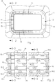
- Figure 1 shows a top view of a hydraulic structure, for example a large hydraulic basin; nevertheless, the method and the system for anchoring a waterproofing liner according to the present invention, are similarly applicable to any type of hydraulic structure, such as dams, artificial basins, canals, or any other possible applications, for example for waterproofing landfill sites and to lay down protective waterproofing liners.
- the hydraulic structure 10 comprises an embankment 11 of rectangular shape that bounds a large basin for containing water; the embankment 11 is obtained by superimposing a plurality of compacted layers of earth and/or rock or other suitable loose material.
- the embankment 11, on the side facing the water, has a sloped inner wall 12 that extends from the top of the embankment 11 downwards to the bottom of the same embankment.
- the inner wall 12 has to be protected by a suitable waterproofing liner 13 consisting, for example, of a plurality of flexible sheets of synthetic material, which are elastically stretchable and sealingly seamed together on a laying surface of said side wall.
- the waterproofing liner 13 can consist of a plurality of sheets of PVC, or another synthetic material such as a "geomembrane", or “geocomposite” provided with a rear protective layer of "geotextile” suitable for a contact with the ground.
- the inner wall 12 of the embankment 11 is protected by a waterproofing liner 13 fastened by seaming, to a plurality of continuous seaming bands 14 of synthetic material, parallely arranged and spaced apart from one another.
- the seaming bands 14 extend from top to bottom in a transverse direction to the wall 12, and are anchored to a plurality of concrete curbs 15, preferably of porous concrete material permeable to water, obtained for example by extrusion or casting, which in the embodiment in figure 1 extend parallel to the longitudinal direction of the wall 12.
- porous concrete material is defined as a mass of gravel, sand or other inert material, of suitable granulometry, mixed with a cement binder in correct proportions, so as to enable the drainage through open pores and interstices of the concrete, of the water that has impregnated the body of the hydraulic structure, conveying the seeped water to the bottom or to a system of discharge conduits.
- the method and the system for anchoring a waterproofing liner to a wall of a hydraulic structure according to the invention are particularly suitable for constructing hydraulic works by superimposing compacted layers of earth, rock and other loose material, in which an homogeneous layer of porous concrete may be formed on the side wall facing the interior or water side, defining with the curbs 15 a laying surface for a waterproofing liner; nevertheless, other applications are not excluded.
- a number of porous concrete curbs 15 are extruded horizontally following longitudinal outline of the wall 12 to be lined; the curbs 15 can be extruded and the embankment 11 can be constructed gradually in successive steps, to form continuous seaming bands 14 progressively during the extrusion of the curbs and formation of the compacted layers of the embankment 11, as explained below.
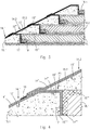
- the hydraulic structure 10 is constructed and the waterproofing liner 13 is anchored to an inner side wall in the following manner: initially, a first base curb 15.1 is formed at the base of the wall 12 of the hydraulic structure 10, by extruding the concrete by a suitable apparatus, for example of the type previously mentioned and normally used for forming road curbs or similar applications.
- a first modular anchor strip 14.1 consisting for example of a strip of a preset length of the same synthetic material as the waterproofing liner 13, or of compatible synthetic material, is superimposed and positioned transversely to the curb 15.1, then being folded downwards against the rear side of the curb to which it can be provisionally fastened by shot nails 17 and/or ballast material 18.
- a first layer 16.1 of loose material is laid down and compacted so as to form the body 10 of the embankment, and at the same time locking a rear anchor portion of each anchor strip 14.1 against the curb 15.1, by the layer 16.1 of compacted loose material; a second curb 15.2 is then extruded, being partially superimposed on the previously extruded base curb 15.1, definitively locking the first set of anchor strips 14.1.
- the curbs 15 have a wedge-shaped cross section, configured with: a first sloping upper surface 15', having substantially the same slope as the wall 12 of the hydraulic structure; a second upper horizontal surface 15" suitable for constituting a resting zone for the curb 15.2, which is extruded subsequently; and a pinching zone PI, figure 4 , for the anchor strips 14.1.
- Each curb 15 further comprises a side surface 15"" along the rear side, which lies on a vertical or slightly slanted plane, against which the rear anchor portion of each seaming strip 14.1 is firmly locked by a layer of loose material 16.1 during laying and compacting operations; similarly the anchor portion of the remaining anchor strips is locked between the upper flat surface 15" of each curb 15, and the lower flat surface 15'" of a curb 15 immediately positioned above.
- the anchor strips 14.1, 14.n will thus be configured with a first fore seaming portion 14' that is superimposed on the sloped upper surface 15' of a respective curb 15.1, 15.n, and with a rear anchor portion 14" intended for being fastened and locked between the upper horizontal surface 15" of the curb 15.1 in the embodiment in figure 4 , and the lower surface 15"' of the curb 15.2, partially superimposed to the preceding curb 15.1.
- the rear anchor portion 14" of each anchor strip 14.1, 14n extends with a vertical length 14"', along the rear surface 15"" of the curb 15.1.
- the single anchor strips 14.1 can be provisionally anchored to the curb 15.1, after a suitable hardening time, for example by shot nails 17, ballast material 18 or other anchor means, maintaining the single anchor strips 14.1 in a stretched condition; a first layer of loose material 16.1 is then laid down and compacted.
- the first anchor strips 14.1 and the first layer of material 16.1 constituting the body of the hydraulic structure 10 are laid down, a second curb 15.2 is extruded being partially superimposed to the preceding curb 15.1; in this manner a firm anchorage of the rear anchor portion 14", 14"', of the first set of anchor strips 14.1 is achieved, the rear anchor portion 14", 14'" being firmly locked between opposite facing surfaces 15" and 15'" of two contiguous curbs 15.1 and 15.2, and by the layer of compacted loose material 16.1.
- the fore seaming portion 14' of each strip of the second set of anchor strips 14.2 is axially laid down and fastened to a respective contiguous anchor strip 14.1 by seaming the fore edge 19 thereof for example to the fore portion 14' of the anchor strip 14.1.
- the seaming of the fore edge 19 of the successive second set of anchor strips 14.2, 14.n to the preceding first set of anchor strips should be close, or as near as possible to the rear anchor portion 14" of the first set of anchor strips 14.1; then a second layer of loose material 16.2 is laid down and compacted on the preceding layer 16.1.
- the construction by superimposed layers of loose material of the hydraulic structure, the laying, locking and seaming of the sets of modular anchor strips 14.1, 14.n that make up the set of seaming bands 14, can continue in the manner disclosed previously, until the hydraulic structure 10 and the liner 13 are completed.
- the curbs 15, as shown in figures 2 and 5 are configured with interlocking elements, for example consisting of triangular elements 20 that extend from the lower surface 15'" of each curb 15, against the rear side 15"" of a curb 15 immediately downstream; naturally, the interlocking elements between curbs 15 can also be configured and differently arranged from what has been shown.
- interlocking elements for example consisting of triangular elements 20 that extend from the lower surface 15'" of each curb 15, against the rear side 15"" of a curb 15 immediately downstream; naturally, the interlocking elements between curbs 15 can also be configured and differently arranged from what has been shown.
- figure 2 shows a partial view of the wall 12 of the hydraulic structure 10, on the side facing the water, after the concrete curbs 15 have been extruded and the set of seaming bands 14 have been anchored to the curbs 15 in the manner previously disclosed.
- a first waterproofing sheet 13.1 is laid down seaming the lateral edges to a respective seaming band 14, along a first continuous seaming line 21, as shown in figure 6 .
- a second waterproofing sheet 13.2 is laid down partially superimposed and seamed to the underlying edge of the preceding waterproofing sheet 13.1, along a second continuous seaming line 22, as shown in the section in figure 8 .
- the seamings 21 and 22 can be performed with the edges of the waterproofing sheets directly overlapped in contact with one another, and/or in contact with the seaming band 14; if the single waterproofing sheets 13.1, 13.n consist of a geocomposite, i.e. comprise a geomembrane coupled with a geotextile, a band of geotextile must be previously removed along the edges to be seamed. The laying down of the entire waterproofing liner 13 can therefore be gradually performed.
- the single waterproofing sheets 13.1, 13.n that make up the waterproofing liner 13 are fastened to seaming bands 14 formed progressively from the bottom up, between a lower and an upper edge or position of the wall 12, transversely extending to a plurality of parallely arranged horizontal extruded concrete curbs 15, locking the single anchor strips 14.1-14.n between curbs 15 extruded in a longitudinal direction of the wall 12 of the hydraulic structure 10, as disclosed previously.
- each transverse seaming band 14 is again serially arranged in the sloping direction of the wall, and superimposed to corresponding concrete curbs 23 consisting of modular blocks made by casting a concrete material in apposite formworks, which transversely extend to the sloped wall 12 of the hydraulic structure, always proceeding from bottom to top; also in this case the entire hydraulic structure is gradually constructed, by superimposing compacted layers 16 of loose material, proceeding simultaneously to casting the single modular blocks 23.1-23.n that make up the concrete curbs 23, and laying down to the curbs 23 a set of seaming bands 14, each consisting of a plurality of serially arranged modular anchor strips 14.1, 14.n axially aligned and seamed to one another, suitably fixing the anchor strips 14.1, 14.n to the modular blocks 23 during casting; also in this case it is preferable that the concrete material is of porous type, as previously mentioned.
- the single concrete curbs 23 are formed by a succession of concrete casts relative to a plurality of axially aligned modular blocks 23.1-23.n, starting from the bottom to the top, in such a manner that the fore end of each modular block 23.1 - 23.n, subsequently cast, comes to rest against the rear end of the previously cast underlying modular block.
- each modular block 23.1, 23.n is cast, a corresponding set of modular anchor strip 14.1, 14.n is laid down by superimposing the fore part 14' thereof longitudinally to the upper surface 23' of a respective modular block 23.
- the rear anchor part 14" of each anchor strip 14.1, 14.n is folded downwards, against the rear surface of the already cast modular block 23, to which can be provisionally fixed by one or more shot nails 17, or in another manner, extending the rear anchor part 14"', which is locked between the modular block 14.2 and the layer 16 of compacted loose material; then the fore seaming part 14' of each anchor strip 14.2 is seamed to a contiguous preceding anchor strip 14.1 such as the fore part of the strip 14.1 in a stretched condition on the previously cast modular block 23.1.
- continuous seaming bands 14 are formed that vertically extend, transversely to the length of and for the entire height of the wall 12 to be protected of any hydraulic structure, to which waterproofing sheets 14.1-14.n of synthetic material may be to sealingly fastened by continuous seaming lines, until an entire waterproofing liner is formed.
- the width of the single seaming bands 14, the space between them and the modular length anchor strips 14.1, 14.n can be of any value; in general they are defined during the design step, according to specific features or requirements of the hydraulic structure.
- the width of the seaming bands 14 and of the anchor strips can be comprised between 20 and 60 cm; moreover the space between centre lines of the seaming bands 14 can be comprised between 100 and 2000 cm.
- the modular length of the anchor strips 14.1, 14.n can be comprised between 130 and 150 cm, according to the slope and/or the height of the wall.
- the length of the fore seaming part and of the rear anchor part for locking to the curbs 15, or to modular blocks 23 of the anchor strips can vary each time and can always be defined during the design step.
- intermediate layer 24 of porous concrete can be laid down suitable for defining with the curbs a laying down surface for the waterproofing liner 13, which is permeable to water.
- FIGs 12, 13 , 14 again by way of example, show other possible solutions for fastening the anchor strips to the modular blocks of the concrete curbs 23; while in the preceding cases, the anchor strips 14.1-14.n are locked between facing side surfaces of extruded curbs, or surfaces of contiguous modular blocks, and between the curbs or modular blocks and layers of compacted loose material 16, in the case of figures 12, 13 and 14 , as indicated by reference number 14.n, the anchor strips are locked between the modular blocks 23n, the intermediate layers of porous concrete 24 and the compacted layers 16 or the underlying ground. In this case the single anchor strips are partially or totally folded around each modular block 23n, as shown, superimposing on and seaming each end of an anchor strip 14n to the facing ends of contiguous anchor strips.
- an anchor strip 14n is shown that is folded into a "Z" shape; the anchor strip 14n comprises an upper longitudinal wing 14.1n, which defines a seaming part for the waterproofing sheets 13, that extends from an edge of the upper surface of the modular block 23n laterally to the left, outside the block 23n, above the intermediate layer in porous concrete material 24.
- the anchor strip 14.n further comprises an intermediate portion 14.2n folded downwards, clamped between opposite surfaces of the modular block 23n and of the left layer of porous concrete 24, and comprises a lower wing 14.3n between the lower surface of the modular block 23.n, and the bottom layer 16n, in which the intermediate portion 14.2n and the lower wing 14.3n define the part for locking the strip to the modular block 23n.
- each anchor strip 14 protrude for a certain length from the respective ends of the modular block 23, to be seamed to the contiguous anchor strips.
- the partially superimposed lateral edges of contiguous waterproofing sheets 13.1, 13.2 can be seamed together and to the upper wings 14.1n of continuous anchor strips, as indicated by the reference numbers 21 and 22, defining continuous seaming lines for a waterproofing liner 13.
- Figure 13 shows a further solution that is substantially similar to those of figure 12 , for which the same reference numbers have been used to indicate similar or equivalent parts; the solution of figure 13 differs from that of figure 12 inasmuch as the anchor strip 14.n is folded into an upturned omega shape, around a corresponding modular block 23.n, with two side wings 14.1n folded to the exterior with respect to the modular block 23.n. Also in this case the waterproofing sheets 13.1, 13.2 can be sealingly seamed together and to at least one of the side wings 14.1n of the anchor strips, the series succession and connection of which forms a continuous seaming band 14 for the waterproofing liner 13.
- Figure 14 shows a variant of the solution of figure 13 ; in the case of figure 14 the same reference numbers as for figure 13 have been used to indicate similar or equivalent parts.
- the solution of figure 14 differs from figure 13 inasmuch as each waterproofing sheet 13.1 is seamed in 21 to a respective side wing 14.1n, as shown; further, with reference number 20 a waterproofing band for covering the modular blocks 23n has been indicated.
- the single sheets 13.1-13n of waterproofing material can also be fixed locally, in preset positions, by mechanical anchors, for example shot nails, pins or the like.
- Figure 15 shows a last solution that is again comparable with the preceding figures 12 and 13 ; in the case of figure 15 , the two side wings 14.1n of the anchor strip 14n have been folded towards the interior, against the upper surface of the modular block 23n, superimposing and seaming them together in 25; in this manner a tubular anchor strip is formed around and along each modular block 23.n, to which the waterproofing sheets 13.1 and 13.2, of the waterproofing liner, can be again seamed in 21 and 22, as shown.
- a method and a system for anchoring a waterproofing liner consisting of a plurality of flexible sheets of synthetic material, which can be sealingly seamed together and to continuous seaming bands of synthetic material, ensuring in this manner a firm anchorage to a plurality of concrete curbs, which are extruded or cast and, which extend longitudinally and/or transversely to a sloped or horizontal wall to be protected of any hydraulic structure made of compacted loose material, or the like.
Landscapes
- Engineering & Computer Science (AREA)
- General Engineering & Computer Science (AREA)
- Structural Engineering (AREA)
- Ocean & Marine Engineering (AREA)
- Mechanical Engineering (AREA)
- Civil Engineering (AREA)
- Environmental & Geological Engineering (AREA)
- Lining And Supports For Tunnels (AREA)
- Road Paving Structures (AREA)
- Building Environments (AREA)
- Bridges Or Land Bridges (AREA)
- Underground Structures, Protecting, Testing And Restoring Foundations (AREA)
- Joining Of Building Structures In Genera (AREA)
Priority Applications (1)
| Application Number | Priority Date | Filing Date | Title |
|---|---|---|---|
| HRP20180823TT HRP20180823T1 (hr) | 2014-04-24 | 2015-04-23 | Postupak i sustav za sidrenje vodonepropusnog vijenca u betonske rubnike hidrauličke strukture |
Applications Claiming Priority (2)
| Application Number | Priority Date | Filing Date | Title |
|---|---|---|---|
| ITMI20140766 | 2014-04-24 | ||
| PCT/EP2015/058788 WO2015162205A1 (en) | 2014-04-24 | 2015-04-23 | Method and system for anchoring a waterproofing liner to concrete curbs of a hydraulic structure |
Publications (2)
| Publication Number | Publication Date |
|---|---|
| EP3134579A1 EP3134579A1 (en) | 2017-03-01 |
| EP3134579B1 true EP3134579B1 (en) | 2018-02-28 |
Family
ID=51033336
Family Applications (1)
| Application Number | Title | Priority Date | Filing Date |
|---|---|---|---|
| EP15719658.5A Active EP3134579B1 (en) | 2014-04-24 | 2015-04-23 | Method and system for anchoring a waterproofing liner to concrete curbs of a hydraulic structure |
Country Status (27)
| Country | Link |
|---|---|
| US (1) | US20170044732A1 (es) |
| EP (1) | EP3134579B1 (es) |
| AP (1) | AP2016009580A0 (es) |
| AU (1) | AU2015250845B2 (es) |
| BR (1) | BR112016023594B1 (es) |
| CA (1) | CA2946786A1 (es) |
| CL (1) | CL2016002659A1 (es) |
| CR (1) | CR20160543A (es) |
| CU (1) | CU24430B1 (es) |
| EA (1) | EA036884B1 (es) |
| EC (1) | ECSP16083448A (es) |
| ES (1) | ES2671033T3 (es) |
| GE (2) | GEAP201814325A (es) |
| HR (1) | HRP20180823T1 (es) |
| IL (1) | IL248461B (es) |
| MA (1) | MA39903A (es) |
| MX (1) | MX378137B (es) |
| MY (1) | MY181234A (es) |
| NI (1) | NI201600158A (es) |
| NZ (1) | NZ726600A (es) |
| PE (1) | PE20161526A1 (es) |
| PH (1) | PH12016502121B1 (es) |
| PT (1) | PT3134579T (es) |
| TR (1) | TR201807421T4 (es) |
| UA (1) | UA118871C2 (es) |
| WO (1) | WO2015162205A1 (es) |
| ZA (1) | ZA201607319B (es) |
Families Citing this family (3)
| Publication number | Priority date | Publication date | Assignee | Title |
|---|---|---|---|---|
| IT201900007234A1 (it) | 2019-05-24 | 2020-11-24 | Carpi Tech Bv | Metodo per la costruzione di una diga in materiale sciolto, con cordoli estrusi e membrana impermeabile protetta |
| CN111119247B (zh) * | 2020-02-21 | 2025-04-01 | 沈阳工业大学 | 一种卫生填埋场衬垫层扣带式锚固装置 |
| CN114908710A (zh) * | 2021-12-31 | 2022-08-16 | 安徽海兴生态科技有限公司 | 一种用于水利工程的河道护坡铺设施工方法 |
Family Cites Families (5)
| Publication number | Priority date | Publication date | Assignee | Title |
|---|---|---|---|---|
| DE2908286C2 (de) * | 1979-03-03 | 1984-04-19 | Alfred Rudolph Gmbh & Co Kg Baustoffgrosshandlung Industrievertretungen, 4300 Essen | Durchsickerter Deich |
| US4659252A (en) * | 1985-09-04 | 1987-04-21 | Parrott, Ely And Hurt Consulting Engineers, Inc. | RCC dam construction and method |
| FR2613394B1 (fr) * | 1987-04-03 | 1989-08-18 | Lisart Jean | Parois etanches pour ouvrages hydrauliques en beton compact et procede de construction de celles-ci |
| IT1304093B1 (it) * | 1998-12-10 | 2001-03-07 | Sibelon Srl | Diga in materiale sciolto e procedimento di impermeabilizzazione |
| SI1790776T1 (sl) * | 2005-11-23 | 2016-09-30 | Carpi Tech B.V. | Postopek za hidroizolacijo in drenažo infiltrirane vode v hidravličnih objektih |
-
2015
- 2015-04-23 PT PT157196585T patent/PT3134579T/pt unknown
- 2015-04-23 ES ES15719658.5T patent/ES2671033T3/es active Active
- 2015-04-23 MA MA039903A patent/MA39903A/fr unknown
- 2015-04-23 MX MX2016013643A patent/MX378137B/es unknown
- 2015-04-23 AP AP2016009580A patent/AP2016009580A0/en unknown
- 2015-04-23 EP EP15719658.5A patent/EP3134579B1/en active Active
- 2015-04-23 CR CR20160543A patent/CR20160543A/es unknown
- 2015-04-23 TR TR2018/07421T patent/TR201807421T4/tr unknown
- 2015-04-23 CA CA2946786A patent/CA2946786A1/en not_active Abandoned
- 2015-04-23 MY MYPI2016703852A patent/MY181234A/en unknown
- 2015-04-23 PE PE2016002110A patent/PE20161526A1/es unknown
- 2015-04-23 AU AU2015250845A patent/AU2015250845B2/en active Active
- 2015-04-23 WO PCT/EP2015/058788 patent/WO2015162205A1/en not_active Ceased
- 2015-04-23 UA UAA201611621A patent/UA118871C2/uk unknown
- 2015-04-23 CU CU2016000154A patent/CU24430B1/es unknown
- 2015-04-23 US US15/306,328 patent/US20170044732A1/en not_active Abandoned
- 2015-04-23 BR BR112016023594-0A patent/BR112016023594B1/pt active IP Right Grant
- 2015-04-23 HR HRP20180823TT patent/HRP20180823T1/hr unknown
- 2015-04-23 GE GEAP201814325A patent/GEAP201814325A/en unknown
- 2015-04-23 NZ NZ726600A patent/NZ726600A/en unknown
- 2015-04-23 GE GEAP201514325A patent/GEP20196985B/en unknown
- 2015-04-23 EA EA201692096A patent/EA036884B1/ru unknown
-
2016
- 2016-10-19 NI NI201600158A patent/NI201600158A/es unknown
- 2016-10-19 CL CL2016002659A patent/CL2016002659A1/es unknown
- 2016-10-24 PH PH12016502121A patent/PH12016502121B1/en unknown
- 2016-10-24 ZA ZA2016/07319A patent/ZA201607319B/en unknown
- 2016-10-25 IL IL248461A patent/IL248461B/en active IP Right Grant
- 2016-11-23 EC ECIEPI201683448A patent/ECSP16083448A/es unknown
Also Published As
Similar Documents
| Publication | Publication Date | Title |
|---|---|---|
| EP3175045B1 (en) | Method, waterproof liner and waterproof panels for installation in basins and canals | |
| US11674393B2 (en) | Method for constructing dam inside dump of inner-dump strip mine | |
| BG63951B1 (bg) | Насипна язовирна стена и хидроизолационен метод | |
| US11001983B2 (en) | Membrane-lined wall | |
| US20160122999A1 (en) | Wall seal system | |
| CN103526770A (zh) | 一种高防渗抗浮桩筏结构及施工方法 | |
| CN210315102U (zh) | 复合式生态装饰面板护坡加筋路基结构 | |
| WO2020240385A1 (en) | Method for constructing an earth and/or rock dam or embankment and a dam or embankment | |
| CN109469496B (zh) | 一种隧道伸缩缝变形协调及排水结构和施工方法 | |
| KR101950098B1 (ko) | 소수의 강관과 강판슈 및 높이가 축소된 구조물에 의한 비개착 터널 시공방법 | |
| AU2015250845B2 (en) | Method and system for anchoring a waterproofing liner to concrete curbs of a hydraulic structure | |
| CN203594041U (zh) | 一种高防渗抗浮桩筏结构 | |
| CN211228563U (zh) | 一种装配式地下水排渗盲沟排水系统 | |
| CN105113715A (zh) | 逆作法施工预制柱及地下结构逆作施工方法 | |
| CN204940700U (zh) | 逆作法施工预制柱及地下结构 | |
| OA18017A (en) | Method and system for anchoring a waterproofing liner to concrete curbs of a hydraulic structure. | |
| EP1514998A1 (de) | Drainierendes Tunnelbauwerk | |
| ITMI20110028A1 (it) | Metodo e dispositivo per la posa e il tensionamento di una copertura impermeabile, per opere idrauliche in materiale sciolto. | |
| CN206189430U (zh) | 用于深覆盖层地基的排水沟 | |
| CN214993572U (zh) | 一种泥石流地区傍山铁路结构 | |
| CN113047233B (zh) | 一种泥石流地区傍山铁路结构及施工方法 | |
| WO2015130165A1 (en) | Piping screen | |
| CN111997030B (zh) | 一种软土增强固化方法 | |
| JP5980579B2 (ja) | 盛土構造物の築造方法 | |
| KR101228021B1 (ko) | 간이 물막이용 구축부재 |
Legal Events
| Date | Code | Title | Description |
|---|---|---|---|
| PUAI | Public reference made under article 153(3) epc to a published international application that has entered the european phase |
Free format text: ORIGINAL CODE: 0009012 |
|
| 17P | Request for examination filed |
Effective date: 20161123 |
|
| AK | Designated contracting states |
Kind code of ref document: A1 Designated state(s): AL AT BE BG CH CY CZ DE DK EE ES FI FR GB GR HR HU IE IS IT LI LT LU LV MC MK MT NL NO PL PT RO RS SE SI SK SM TR |
|
| AX | Request for extension of the european patent |
Extension state: BA ME |
|
| RAX | Requested extension states of the european patent have changed |
Extension state: BA Payment date: 20161123 |
|
| REG | Reference to a national code |
Ref country code: DE Ref legal event code: R079 Ref document number: 602015008428 Country of ref document: DE Free format text: PREVIOUS MAIN CLASS: E02B0003160000 Ipc: E02B0003100000 |
|
| RIC1 | Information provided on ipc code assigned before grant |
Ipc: E02B 3/10 20060101AFI20170808BHEP Ipc: E02B 3/14 20060101ALI20170808BHEP Ipc: E02B 3/12 20060101ALI20170808BHEP Ipc: E02B 3/16 20060101ALI20170808BHEP |
|
| GRAP | Despatch of communication of intention to grant a patent |
Free format text: ORIGINAL CODE: EPIDOSNIGR1 |
|
| INTG | Intention to grant announced |
Effective date: 20170919 |
|
| GRAS | Grant fee paid |
Free format text: ORIGINAL CODE: EPIDOSNIGR3 |
|
| GRAA | (expected) grant |
Free format text: ORIGINAL CODE: 0009210 |
|
| AK | Designated contracting states |
Kind code of ref document: B1 Designated state(s): AL AT BE BG CH CY CZ DE DK EE ES FI FR GB GR HR HU IE IS IT LI LT LU LV MC MK MT NL NO PL PT RO RS SE SI SK SM TR |
|
| AX | Request for extension of the european patent |
Extension state: BA |
|
| REG | Reference to a national code |
Ref country code: GB Ref legal event code: FG4D Ref country code: CH Ref legal event code: EP |
|
| REG | Reference to a national code |
Ref country code: AT Ref legal event code: REF Ref document number: 974275 Country of ref document: AT Kind code of ref document: T Effective date: 20180315 |
|
| REG | Reference to a national code |
Ref country code: IE Ref legal event code: FG4D |
|
| REG | Reference to a national code |
Ref country code: DE Ref legal event code: R096 Ref document number: 602015008428 Country of ref document: DE |
|
| RAP2 | Party data changed (patent owner data changed or rights of a patent transferred) |
Owner name: CARPI TECH B.V. |
|
| REG | Reference to a national code |
Ref country code: HR Ref legal event code: TUEP Ref document number: P20180823 Country of ref document: HR Ref country code: RO Ref legal event code: EPE |
|
| REG | Reference to a national code |
Ref country code: PT Ref legal event code: SC4A Ref document number: 3134579 Country of ref document: PT Date of ref document: 20180604 Kind code of ref document: T Free format text: AVAILABILITY OF NATIONAL TRANSLATION Effective date: 20180525 Ref country code: ES Ref legal event code: FG2A Ref document number: 2671033 Country of ref document: ES Kind code of ref document: T3 Effective date: 20180604 |
|
| REG | Reference to a national code |
Ref country code: FR Ref legal event code: PLFP Year of fee payment: 4 |
|
| REG | Reference to a national code |
Ref country code: NL Ref legal event code: MP Effective date: 20180228 |
|
| REG | Reference to a national code |
Ref country code: LT Ref legal event code: MG4D |
|
| PG25 | Lapsed in a contracting state [announced via postgrant information from national office to epo] |
Ref country code: FI Free format text: LAPSE BECAUSE OF FAILURE TO SUBMIT A TRANSLATION OF THE DESCRIPTION OR TO PAY THE FEE WITHIN THE PRESCRIBED TIME-LIMIT Effective date: 20180228 Ref country code: LT Free format text: LAPSE BECAUSE OF FAILURE TO SUBMIT A TRANSLATION OF THE DESCRIPTION OR TO PAY THE FEE WITHIN THE PRESCRIBED TIME-LIMIT Effective date: 20180228 Ref country code: NL Free format text: LAPSE BECAUSE OF FAILURE TO SUBMIT A TRANSLATION OF THE DESCRIPTION OR TO PAY THE FEE WITHIN THE PRESCRIBED TIME-LIMIT Effective date: 20180228 Ref country code: CY Free format text: LAPSE BECAUSE OF FAILURE TO SUBMIT A TRANSLATION OF THE DESCRIPTION OR TO PAY THE FEE WITHIN THE PRESCRIBED TIME-LIMIT Effective date: 20180228 Ref country code: NO Free format text: LAPSE BECAUSE OF FAILURE TO SUBMIT A TRANSLATION OF THE DESCRIPTION OR TO PAY THE FEE WITHIN THE PRESCRIBED TIME-LIMIT Effective date: 20180528 |
|
| REG | Reference to a national code |
Ref country code: MA Ref legal event code: VAGR Ref document number: 39903 Country of ref document: MA Kind code of ref document: B1 |
|
| REG | Reference to a national code |
Ref country code: HR Ref legal event code: T1PR Ref document number: P20180823 Country of ref document: HR |
|
| REG | Reference to a national code |
Ref country code: DE Ref legal event code: R081 Ref document number: 602015008428 Country of ref document: DE Owner name: CARPI TECH B.V., NL Free format text: FORMER OWNER: CARPI TECH B.V., BERKEL EN RODENRIJS, NL |
|
| PG25 | Lapsed in a contracting state [announced via postgrant information from national office to epo] |
Ref country code: RS Free format text: LAPSE BECAUSE OF FAILURE TO SUBMIT A TRANSLATION OF THE DESCRIPTION OR TO PAY THE FEE WITHIN THE PRESCRIBED TIME-LIMIT Effective date: 20180228 Ref country code: BG Free format text: LAPSE BECAUSE OF FAILURE TO SUBMIT A TRANSLATION OF THE DESCRIPTION OR TO PAY THE FEE WITHIN THE PRESCRIBED TIME-LIMIT Effective date: 20180528 Ref country code: LV Free format text: LAPSE BECAUSE OF FAILURE TO SUBMIT A TRANSLATION OF THE DESCRIPTION OR TO PAY THE FEE WITHIN THE PRESCRIBED TIME-LIMIT Effective date: 20180228 Ref country code: SE Free format text: LAPSE BECAUSE OF FAILURE TO SUBMIT A TRANSLATION OF THE DESCRIPTION OR TO PAY THE FEE WITHIN THE PRESCRIBED TIME-LIMIT Effective date: 20180228 |
|
| PG25 | Lapsed in a contracting state [announced via postgrant information from national office to epo] |
Ref country code: EE Free format text: LAPSE BECAUSE OF FAILURE TO SUBMIT A TRANSLATION OF THE DESCRIPTION OR TO PAY THE FEE WITHIN THE PRESCRIBED TIME-LIMIT Effective date: 20180228 Ref country code: IT Free format text: LAPSE BECAUSE OF FAILURE TO SUBMIT A TRANSLATION OF THE DESCRIPTION OR TO PAY THE FEE WITHIN THE PRESCRIBED TIME-LIMIT Effective date: 20180228 Ref country code: AL Free format text: LAPSE BECAUSE OF FAILURE TO SUBMIT A TRANSLATION OF THE DESCRIPTION OR TO PAY THE FEE WITHIN THE PRESCRIBED TIME-LIMIT Effective date: 20180228 Ref country code: PL Free format text: LAPSE BECAUSE OF FAILURE TO SUBMIT A TRANSLATION OF THE DESCRIPTION OR TO PAY THE FEE WITHIN THE PRESCRIBED TIME-LIMIT Effective date: 20180228 |
|
| REG | Reference to a national code |
Ref country code: DE Ref legal event code: R097 Ref document number: 602015008428 Country of ref document: DE |
|
| PG25 | Lapsed in a contracting state [announced via postgrant information from national office to epo] |
Ref country code: SK Free format text: LAPSE BECAUSE OF FAILURE TO SUBMIT A TRANSLATION OF THE DESCRIPTION OR TO PAY THE FEE WITHIN THE PRESCRIBED TIME-LIMIT Effective date: 20180228 Ref country code: MC Free format text: LAPSE BECAUSE OF FAILURE TO SUBMIT A TRANSLATION OF THE DESCRIPTION OR TO PAY THE FEE WITHIN THE PRESCRIBED TIME-LIMIT Effective date: 20180228 Ref country code: DK Free format text: LAPSE BECAUSE OF FAILURE TO SUBMIT A TRANSLATION OF THE DESCRIPTION OR TO PAY THE FEE WITHIN THE PRESCRIBED TIME-LIMIT Effective date: 20180228 Ref country code: SM Free format text: LAPSE BECAUSE OF FAILURE TO SUBMIT A TRANSLATION OF THE DESCRIPTION OR TO PAY THE FEE WITHIN THE PRESCRIBED TIME-LIMIT Effective date: 20180228 Ref country code: CZ Free format text: LAPSE BECAUSE OF FAILURE TO SUBMIT A TRANSLATION OF THE DESCRIPTION OR TO PAY THE FEE WITHIN THE PRESCRIBED TIME-LIMIT Effective date: 20180228 |
|
| REG | Reference to a national code |
Ref country code: BE Ref legal event code: MM Effective date: 20180430 |
|
| PLBE | No opposition filed within time limit |
Free format text: ORIGINAL CODE: 0009261 |
|
| STAA | Information on the status of an ep patent application or granted ep patent |
Free format text: STATUS: NO OPPOSITION FILED WITHIN TIME LIMIT |
|
| REG | Reference to a national code |
Ref country code: IE Ref legal event code: MM4A |
|
| PG25 | Lapsed in a contracting state [announced via postgrant information from national office to epo] |
Ref country code: LU Free format text: LAPSE BECAUSE OF NON-PAYMENT OF DUE FEES Effective date: 20180423 |
|
| 26N | No opposition filed |
Effective date: 20181129 |
|
| PG25 | Lapsed in a contracting state [announced via postgrant information from national office to epo] |
Ref country code: BE Free format text: LAPSE BECAUSE OF NON-PAYMENT OF DUE FEES Effective date: 20180430 Ref country code: SI Free format text: LAPSE BECAUSE OF FAILURE TO SUBMIT A TRANSLATION OF THE DESCRIPTION OR TO PAY THE FEE WITHIN THE PRESCRIBED TIME-LIMIT Effective date: 20180228 |
|
| REG | Reference to a national code |
Ref country code: GR Ref legal event code: EP Ref document number: 20180401443 Country of ref document: GR Effective date: 20190225 |
|
| PG25 | Lapsed in a contracting state [announced via postgrant information from national office to epo] |
Ref country code: IE Free format text: LAPSE BECAUSE OF NON-PAYMENT OF DUE FEES Effective date: 20180423 |
|
| VSFP | Annual fee paid to validation state [announced via postgrant information from national office to epo] |
Ref country code: MA Payment date: 20180919 Year of fee payment: 4 |
|
| REG | Reference to a national code |
Ref country code: HR Ref legal event code: ODRP Ref document number: P20180823 Country of ref document: HR Payment date: 20190405 Year of fee payment: 5 |
|
| PG25 | Lapsed in a contracting state [announced via postgrant information from national office to epo] |
Ref country code: MT Free format text: LAPSE BECAUSE OF NON-PAYMENT OF DUE FEES Effective date: 20180423 |
|
| VSFP | Annual fee paid to validation state [announced via postgrant information from national office to epo] |
Ref country code: MA Payment date: 20180919 Year of fee payment: 5 |
|
| REG | Reference to a national code |
Ref country code: HR Ref legal event code: ODRP Ref document number: P20180823 Country of ref document: HR Payment date: 20200407 Year of fee payment: 6 |
|
| PG25 | Lapsed in a contracting state [announced via postgrant information from national office to epo] |
Ref country code: HU Free format text: LAPSE BECAUSE OF FAILURE TO SUBMIT A TRANSLATION OF THE DESCRIPTION OR TO PAY THE FEE WITHIN THE PRESCRIBED TIME-LIMIT; INVALID AB INITIO Effective date: 20150423 |
|
| REG | Reference to a national code |
Ref country code: HR Ref legal event code: ODRP Ref document number: P20180823 Country of ref document: HR Payment date: 20210402 Year of fee payment: 7 |
|
| REG | Reference to a national code |
Ref country code: HR Ref legal event code: ODRP Ref document number: P20180823 Country of ref document: HR Payment date: 20220406 Year of fee payment: 8 |
|
| PGFP | Annual fee paid to national office [announced via postgrant information from national office to epo] |
Ref country code: MK Payment date: 20220401 Year of fee payment: 8 |
|
| REG | Reference to a national code |
Ref country code: HR Ref legal event code: ODRP Ref document number: P20180823 Country of ref document: HR Payment date: 20230404 Year of fee payment: 9 |
|
| REG | Reference to a national code |
Ref country code: HR Ref legal event code: ODRP Ref document number: P20180823 Country of ref document: HR Payment date: 20240405 Year of fee payment: 10 |
|
| REG | Reference to a national code |
Ref country code: HR Ref legal event code: ODRP Ref document number: P20180823 Country of ref document: HR Payment date: 20250414 Year of fee payment: 11 |
|
| PGFP | Annual fee paid to national office [announced via postgrant information from national office to epo] |
Ref country code: DE Payment date: 20250429 Year of fee payment: 11 |
|
| PGFP | Annual fee paid to national office [announced via postgrant information from national office to epo] |
Ref country code: GB Payment date: 20250428 Year of fee payment: 11 Ref country code: ES Payment date: 20250505 Year of fee payment: 11 |
|
| PGFP | Annual fee paid to national office [announced via postgrant information from national office to epo] |
Ref country code: IS Payment date: 20250416 Year of fee payment: 11 |
|
| PGFP | Annual fee paid to national office [announced via postgrant information from national office to epo] |
Ref country code: HR Payment date: 20250414 Year of fee payment: 11 |
|
| PGFP | Annual fee paid to national office [announced via postgrant information from national office to epo] |
Ref country code: PT Payment date: 20250402 Year of fee payment: 11 |
|
| PGFP | Annual fee paid to national office [announced via postgrant information from national office to epo] |
Ref country code: FR Payment date: 20250425 Year of fee payment: 11 |
|
| PGFP | Annual fee paid to national office [announced via postgrant information from national office to epo] |
Ref country code: GR Payment date: 20250430 Year of fee payment: 11 |
|
| PGFP | Annual fee paid to national office [announced via postgrant information from national office to epo] |
Ref country code: CH Payment date: 20250501 Year of fee payment: 11 |
|
| PGFP | Annual fee paid to national office [announced via postgrant information from national office to epo] |
Ref country code: RO Payment date: 20250407 Year of fee payment: 11 Ref country code: AT Payment date: 20250423 Year of fee payment: 11 |
|
| PGFP | Annual fee paid to national office [announced via postgrant information from national office to epo] |
Ref country code: TR Payment date: 20250418 Year of fee payment: 11 |
|
| VSFP | Annual fee paid to validation state [announced via postgrant information from national office to epo] |
Ref country code: MA Payment date: 20230420 Year of fee payment: 9 |
|
| VSFP | Annual fee paid to validation state [announced via postgrant information from national office to epo] |
Ref country code: MA Payment date: 20240416 Year of fee payment: 10 Ref country code: MA Payment date: 20220411 Year of fee payment: 8 Ref country code: MA Payment date: 20210420 Year of fee payment: 7 Ref country code: MA Payment date: 20200413 Year of fee payment: 6 |
|
| VSFP | Annual fee paid to validation state [announced via postgrant information from national office to epo] |
Ref country code: MA Payment date: 20250425 Year of fee payment: 11 Ref country code: MA Payment date: 20190417 Year of fee payment: 5 |
|
| REG | Reference to a national code |
Ref country code: CH Ref legal event code: U11 Free format text: ST27 STATUS EVENT CODE: U-0-0-U10-U11 (AS PROVIDED BY THE NATIONAL OFFICE) Effective date: 20260501 |